EP4270392A1 - Audio noise reduction method and system - Google Patents
Audio noise reduction method and system Download PDFInfo
- Publication number
- EP4270392A1 EP4270392A1 EP20967279.9A EP20967279A EP4270392A1 EP 4270392 A1 EP4270392 A1 EP 4270392A1 EP 20967279 A EP20967279 A EP 20967279A EP 4270392 A1 EP4270392 A1 EP 4270392A1
- Authority
- EP
- European Patent Office
- Prior art keywords
- audio
- frequency
- signal
- gain
- audio signal
- Prior art date
- Legal status (The legal status is an assumption and is not a legal conclusion. Google has not performed a legal analysis and makes no representation as to the accuracy of the status listed.)
- Pending
Links
Images


Classifications
-
- H—ELECTRICITY
- H04—ELECTRIC COMMUNICATION TECHNIQUE
- H04R—LOUDSPEAKERS, MICROPHONES, GRAMOPHONE PICK-UPS OR LIKE ACOUSTIC ELECTROMECHANICAL TRANSDUCERS; ELECTRIC HEARING AIDS; PUBLIC ADDRESS SYSTEMS
- H04R3/00—Circuits for transducers
- H04R3/04—Circuits for transducers for correcting frequency response
-
- G—PHYSICS
- G10—MUSICAL INSTRUMENTS; ACOUSTICS
- G10L—SPEECH ANALYSIS TECHNIQUES OR SPEECH SYNTHESIS; SPEECH RECOGNITION; SPEECH OR VOICE PROCESSING TECHNIQUES; SPEECH OR AUDIO CODING OR DECODING
- G10L21/00—Speech or voice signal processing techniques to produce another audible or non-audible signal, e.g. visual or tactile, in order to modify its quality or its intelligibility
- G10L21/02—Speech enhancement, e.g. noise reduction or echo cancellation
-
- H—ELECTRICITY
- H04—ELECTRIC COMMUNICATION TECHNIQUE
- H04R—LOUDSPEAKERS, MICROPHONES, GRAMOPHONE PICK-UPS OR LIKE ACOUSTIC ELECTROMECHANICAL TRANSDUCERS; ELECTRIC HEARING AIDS; PUBLIC ADDRESS SYSTEMS
- H04R3/00—Circuits for transducers
- H04R3/005—Circuits for transducers for combining the signals of two or more microphones
-
- H—ELECTRICITY
- H04—ELECTRIC COMMUNICATION TECHNIQUE
- H04R—LOUDSPEAKERS, MICROPHONES, GRAMOPHONE PICK-UPS OR LIKE ACOUSTIC ELECTROMECHANICAL TRANSDUCERS; ELECTRIC HEARING AIDS; PUBLIC ADDRESS SYSTEMS
- H04R1/00—Details of transducers, loudspeakers or microphones
- H04R1/46—Special adaptations for use as contact microphones, e.g. on musical instrument, on stethoscope
-
- H—ELECTRICITY
- H04—ELECTRIC COMMUNICATION TECHNIQUE
- H04R—LOUDSPEAKERS, MICROPHONES, GRAMOPHONE PICK-UPS OR LIKE ACOUSTIC ELECTROMECHANICAL TRANSDUCERS; ELECTRIC HEARING AIDS; PUBLIC ADDRESS SYSTEMS
- H04R2410/00—Microphones
- H04R2410/05—Noise reduction with a separate noise microphone
Definitions
- This specification relates to the audio signal processing field, and in particular, to an audio denoising method and system.
- a capture device of a signal source is an air-conduction component, that is, an air-conduction microphone.
- an air-conduction microphone In a high noise scenario, a valid audio signal captured by the air-conduction microphone is almost completely surrounded by noise.
- a bone-conduction microphone is used on an electronic product such as a headphone, and there are more and more applications using bone-conduction microphones to receive voice signals.
- More and more electronic devices combine an air-conduction microphone and a bone-conduction microphone having different features, the air-conduction microphone is used to pick an external audio signal, the bone-conduction microphone is used to pick a vibration signal of a sound generation part, and voice enhancement processing and fusion are performed on the picked signals.
- a bone-conduction component may directly pick a vibration signal of a sound generation part, which can reduce the impact of ambient noise to some extent.
- solutions combining an air-conduction microphone and a bone-conduction microphone there is a solution with a plurality of air-conduction microphones and one bone-conduction microphone, and there is also a solution with one air-conduction microphone and one bone-conduction microphone.
- voice quality of a single air-conduction microphone is poor, and voice quality of a bone-conduction microphone is also polluted by external noise to some extent.
- a single-microphone denoising algorithm such as a spectral subtraction method or a Wiener filtering method
- a microphone array denoising algorithm such as a fixed beamforming method or an adaptive beamforming method.
- a conventional denoising algorithm such as spectral subtraction or Wiener filtering has a very limited effect on increasing a signal-to-noise ratio (denoising strength is insufficient); and some improved algorithms increase denoising strength but cause great voice distortion, and there is an obvious noise residue in a high-frequency part.
- a new audio denoising method and system is needed for preserving voice fidelity and intelligibility while filtering noise and increasing a signal-to-noise ratio in a high noise scenario.
- This specification provides a new audio denoising method and system to preserve voice fidelity and intelligibility while filtering noise and increasing a signal-to-noise ratio in a high noise scenario.
- this specification provides an audio denoising method, including: obtaining at least one modulation parameter related to a frequency of a to-be-processed audio signal; and performing gain processing on the to-be-processed audio signal based on a gain coefficient corresponding to the at least one modulation parameter to obtain a target audio signal.
- this specification further provides an audio denoising system, including: at least one storage medium, storing at least one set of instruction for audio denoising; and at least one processor in communication with the at least one storage medium, when the audio denoising system operates, the at least one processor reads the at least one instruction set, and performs the audio denoising method based on an instruction of the at least one set of instruction according to the first aspect.
- optimization processing may be further performed on an audio signal on a basis of a conventional audio denoising method by using a frequency as a unit.
- gain processing may be performed on the audio signal based on at least one of a plurality of frequency units of the audio signal or signal-to-noise ratios corresponding to the plurality of frequency units.
- a gain coefficient(s) may be generated based on the plurality of frequency units of the audio signal and the signal-to-noise ratios corresponding to the plurality of frequency units, and gain processing is performed on the audio signal by using the gain coefficient.
- the audio signal may be further optimized on a basis of the conventional audio denoising method. More audio signals corresponding to frequencies including more valid audio signals are preserved, while less audio signals corresponding to frequencies including fewer valid audio signals are preserved. In this way, voice fidelity and intelligibility are preserved while noise is filtered, and the signal-to-noise ratio is increased.
- a flowchart used in this specification shows operations implemented by the system according to some embodiments of this specification. It should be clearly understood that operations in the flowchart may not be implemented sequentially. Conversely, the operations may be implemented in a reverse sequence or simultaneously. In addition, one or more other operations may be added to the flowchart, and one or more operations may be removed from the flowchart.
- some denoising algorithms preserve audio signals on all frequencies almost evenly. In other words, the denoising algorithms perform same denoising processing on audio signals of different frequencies. Therefore, proportions of signals preserved on different frequencies of audio signals processed by using the denoising algorithms are consistent.
- valid audio signals included in different frequencies are different. For example, a valid audio signal (that is, a human voiceprint) included in a low-frequency part in an audio signal carrying a noise signal is higher than a valid audio signal included in a high-frequency part.
- the denoising algorithms do not consider a frequency factor of the audio signals, resulting in roughly consistent denoising strength across different frequencies.
- a high-strength denoising algorithm when used to perform denoising processing on an audio signal carrying a noise signal, while a noise signal in a high-frequency part is reduced, a valid audio signal in a low-frequency part is discarded, thus causes voice distortion.
- a low-strength denoising algorithm when used to perform denoising processing on an audio signal carrying a noise signal, there is an obvious noise residue in a high-frequency part, resulting in poor audio denoising effect.
- the valid audio signal may be an important audio signal carried by the audio signal.
- the noise signal may be an audio signal other than the valid audio signal.
- the valid audio signal may be a human voice signal when a user of the call speaks, and the noise signal may be ambient noise, for example, sound of a vehicle, sound of whistling, etc.
- the valid audio signal may be an audio signal of chirping, and the noise signal may be sound of a wind, sound of water, or the like.
- a voice call is taken as an example for description in the following descriptions, where the valid audio signal is a human voice signal when a user of the call speaks, and the noise signal may be ambient noise.
- the noise signal and the valid audio signal are both signals obtained by using an estimation algorithm.
- the noise signal may be estimated by using a noise estimation algorithm.
- the valid audio signal may be obtained through estimation by subtracting the noise signal from an original audio signal.
- different gain processing may be performed on audio signals of different frequencies based on parameters related to the frequencies of the audio signals.
- gain processing can be performed on each frequency separately using frequencies of audio signals as units based on a feature of each frequency, so that proportions of audio denoising on all frequencies are uneven, so that more audio signals corresponding to frequency parts including more valid audio signals are preserved, while less audio signals corresponding to frequency parts including fewer valid audio signals are preserved. In this way, fidelity and intelligibility of an audio signal are improved while quality of the audio signal is improved and noise is reduced.
- the fidelity may be a similarity between an audio signal output by a device and an audio signal received by the device.
- the higher fidelity the higher the similarity between the audio signal output by the device and the audio signal received by the device.
- the intelligibility may also be voice articulation. The higher the voice articulation, the higher the intelligibility.
- FIG. 1 is a schematic device diagram of an audio denoising system 100 (hereinafter referred to as the system 100).
- the system 100 may be applied to an electronic device 200.
- the electronic device 200 may be a wireless headphone, a wired headphone, or an intelligent wearable device, for example, a device having a voice capture function and a voice playing function such as smart glasses, a smart helmet, or a smart watch.
- the electronic device 200 may also be a mobile device, a tablet computer, a notebook computer, a built-in apparatus of a motor vehicle, or the like, or any combination thereof.
- the mobile device may include a smart household device, a smart mobile device, a virtual reality device, an augmented reality device, or the like, or any combination thereof.
- the smart mobile device may include a mobile phone, a personal digital assistant, a game device, a navigation device, an ultra-mobile personal computer (Ultra-mobile Personal Computer, UMPC), or the like, or any combination thereof.
- the smart household device may include a smart TV, a desktop computer, or the like, or any combination thereof.
- the virtual reality device or the augmented reality device may include a virtual reality helmet, virtual reality glasses, a virtual reality patch, an augmented reality helmet, augmented reality glasses, an augmented reality patch, or the like, or any combination thereof.
- the built-in apparatus of the motor vehicle may include a vehicle-mounted computer, a vehicle-mounted television, or the like.
- the electronic device 200 may store data or an instruction(s) for performing an audio denoising method described in this specification, and may execute the data and/or the instruction(s).
- the electronic device 200 may receive a to-be-processed audio signal, and execute data or an instruction of the audio denoising method described in this specification, to perform audio denoising processing on the to-be-processed audio signal, and generate a target audio signal.
- the audio denoising method is described in other parts of this specification. For example, the audio denoising method is described in the descriptions of FIG. 2 to FIG. 6 .
- the to-be-processed audio signal includes at least a valid audio signal.
- the to-be-processed audio signal may also include a noise signal.
- the to-be-processed audio signal may be an audio signal locally stored by the electronic device 200, or may be an audio signal output by an audio capture device of the electronic device 200, or may be an audio signal sent by another device to the electronic device 200, or the like.
- the audio capture device may be integrated with the electronic device 200, or may be an externally connected device that is communicatively connected to the electronic device 200.
- the electronic device 200 may include at least one storage medium 230 and at least one processor 220.
- the electronic device 200 may further include a communications port 250 and an internal communications bus 210.
- the electronic device 200 may further include an I/O component 260.
- the electronic device 200 may further include a microphone module 240.
- the internal communications bus 210 may connect different system components, including the storage medium 230, the processor 220, and the microphone module 240.
- the I/O component 260 supports inputting/outputting between the electronic device 200 and another component.
- the electronic device 200 may obtain the to-be-processed audio signal by using the I/O component 260.
- the communications port 250 is used by the electronic device 200 to perform external data communication.
- the electronic device 200 may also obtain the to-be-processed audio signal by using the communications port 250.
- the at least one storage medium 230 may include a data storage device.
- the data storage apparatus may be a non-transitory storage medium, or may be a transitory storage medium.
- the data storage apparatus may include one or more of a magnetic disk 232, a read-only memory (ROM) 234, or a random access memory (RAM) 236.
- the storage medium 230 further includes at least one instruction set stored in the data storage apparatus, where the instruction set is used for audio denoising.
- the instruction is computer program code, where the computer program code may include a program, a routine, an object, a component, a data structure, a process, a module, or the like for performing the audio denoising method provided in this specification.
- the at least one storage medium 230 may also store the to-be-processed audio signal.
- the at least one storage medium 230 may further prestore a gain function, where the gain function is described in detail in subsequent descriptions.
- the at least one processor 220 may be communicatively connected to the at least one storage medium 230 by using the internal communications bus 210.
- the communication connection is a connection in any form and capable of directly or indirectly receiving information.
- the at least one processor 220 is configured to execute the at least one instruction set.
- the at least one processor 220 reads the at least one instruction set, and performs, based on an instruction of the at least one instruction set, the audio denoising method provided by this specification.
- the processor 220 may perform all steps included in the audio denoising method.
- the processor 220 may be in a form of one or more processors.
- the processor 220 may include one or more hardware processors, for example, a microcontroller, a microprocessor, a reduced instruction set computer (RISC), an application-specific integrated circuit (ASIC), an application-specific instruction set processor (ASIP), a central processing unit (CPU), a graphics processing unit (GPU), a physical processing unit (PPU), a microcontroller unit, a digital signal processor (DSP), a field programmable gate array (FPGA), an advanced RISC machine (ARM), a programmable logic device (PLD), or any other types of circuit or processor that can implement one or more functions, and the like, or any combination thereof.
- a microcontroller for example, a microcontroller, a microprocessor, a reduced instruction set computer (RISC), an application-specific integrated circuit (ASIC), an application-specific instruction set processor (ASIP), a central processing unit (CPU), a graphics processing unit (GPU), a physical processing unit (PPU), a microcontroller unit, a digital signal processor (DSP
- the electronic device 200 in this specification may further include a plurality of processors. Therefore, operations and/or method steps disclosed in this specification may be performed by one processor in this specification, or may be performed jointly by a plurality of processors. For example, if the processor 220 of the electronic device 200 in this specification performs step A and step B, it should be understood that step A and step B may also be performed jointly or separately by two different processors 220 (for example, the first processor performs step A, and the second processor performs step B, or the first processor and the second processor jointly perform step A and step B).
- the electronic device 200 may further include the microphone module 240.
- the microphone module 240 may be an audio capture device of the electronic device 200.
- the microphone module 240 may be configured to obtain a local audio signal, and output a microphone signal, that is, an electrical signal carrying audio information.
- the to-be-processed audio signal may be the microphone signal output by the microphone module 240.
- the microphone module 240 may be communicatively connected to the at least one processor 220 and the at least one storage medium 230.
- the at least one processor 220 may read the at least one instruction set, obtain the microphone signal based on the instruction of the at least one instruction set, and perform the audio denoising method provided in this specification.
- the microphone module 240 may be integrated with the electronic device 200, or may be a device externally connected to the electronic device 200.
- the microphone module 240 may be configured to obtain a local audio signal, and output a microphone signal, that is, electrical signal carrying audio information.
- the microphone module 240 may be an out-of-ear microphone module or may be an in-ear microphone module.
- the microphone module 240 may be a microphone disposed out of an auditory canal, or may be a microphone disposed in an auditory canal.
- the microphone module 240 may be a first-type microphone, and may be a microphone directly capturing a human body vibration signal, for example, a bone-conduction microphone.
- the microphone module 240 may also be a second-type microphone, and may be a microphone directly capturing an air vibration signal, for example, an air-conduction microphone.
- the microphone module 240 may also be a combination of a first-type microphone and a second-type microphone. Certainly, the microphone module 240 may also be another type of microphone. For example, the microphone module 240 may be an optical microphone, or may be a microphone for receiving an electromyographic signal. For ease of presentation, in the following descriptions of the present disclosure, the bone-conduction microphone is used as an example of the first-type microphone, and the air-conduction microphone is used as an example of the second-type microphone for description.
- the bone-conduction microphone may include a vibration sensor, for example, an optical vibration sensor or an acceleration sensor.
- the vibration sensor may capture a mechanical vibration signal (for example, a signal generated by a vibration generated by the skin or bones when a user speaks), and convert the mechanical vibration signal into an electrical signal.
- the mechanical vibration signal mainly refers to a vibration propagated by a solid.
- the bone-conduction microphone captures, by touching the skin or bones of the user by using the vibration sensor or a vibration component connected to the vibration sensor, a vibration signal generated by the bones or skin when the user makes a sound, and converts the vibration signal into an electrical signal.
- the vibration sensor may be a device that is sensitive to a mechanical vibration but insensitive to an air vibration (that is, a capability of responding to the mechanical vibration by the vibration sensor exceeds a capability of responding to the air vibration by the vibration sensor). Because the bone-conduction microphone can directly pick a vibration signal of a sound generation part, the bone-conduction microphone can reduce impact of ambient noise.
- the air-conduction microphone captures an air vibration signal caused when a user makes a sound, and converts the air vibration signal into an electrical signal.
- the air-conduction microphone may be a separate air-conduction microphone, or may be a microphone array including two or more air-conduction microphones.
- the microphone array may be a beamforming microphone array or another similar microphone array. Sound coming from different directions or positions may be captured by using the microphone array.
- the first-type microphone may output a first audio signal.
- the second-type microphone may output a second audio signal.
- the system 100 may receive the to-be-processed audio signal, and perform the audio denoising method described in this specification to perform audio denoising processing on the to-be-processed audio signal, generate and output the target audio signal.
- the to-be-processed audio signal may be an original audio signal that is not denoised by using an audio denoising algorithm, or may be an audio signal obtained after the original audio signal is processed by using a first audio denoising algorithm.
- the original audio signal may be the first audio signal, or may be the second audio signal, or may be an audio signal obtained through fusion of the first audio signal and the second audio signal.
- the to-be-processed audio signal may be an audio signal obtained after the first audio signal is processed by using the first audio denoising method, or may be an audio signal obtained after the second audio signal is processed by using the first audio denoising method, or may be an audio signal obtained after the audio signal obtained through fusion of the first audio signal and the second audio signal is processed by using the first audio denoising method.
- the first audio denoising algorithm may be a conventional audio denoising algorithm, for example, at least one of: a spectral subtraction method, a Wiener filtering method, an MMSE algorithm, or an MMSE-based improved algorithm, or any combination thereof.
- the target audio signal obtained after denoising processing performed by the system 100 preserves more audio signals including more valid audio signals. Therefore, voice quality of the target audio signal can be improved, and voice fidelity and intelligibility can be improved.
- FIG. 2 is a flowchart of an audio denoising method P100 according to an embodiment of this specification.
- the method P100 may include the following step performed by at least one processor 220: S120: obtaining a modulation parameter(s) related to a frequency of a to-be-processed audio signal.
- audio denoising may be performed on the to-be-processed audio signal by using the frequency as a unit.
- a frequency interval of an audio may be divided into a plurality of frequency units, that is, frequency intervals with preset bandwidths.
- a plurality of frequency units may be represented by a plurality of frequencies.
- gain processing may be performed on an audio signal corresponding to each frequency unit or each frequency band unit in the frequency interval separately, so that more audio signals corresponding to frequency parts (for example, frequency intervals with high signal-to-noise ratios SNRs) including more valid audio signals are preserved, while less audio signals corresponding to frequency parts (for example, frequency intervals with a low signal-to-noise ratios SNRs) including fewer valid audio signals are preserved. In this way, quality of the audio signal is improved.
- the high-frequency part in the audio may be suppressed while the low-frequency part is amplified to improve quality of the entire audio.
- articulation of the valid audio signal in the audio signal is improved while noise in the audio signal is reduced.
- the modulation parameter may be a parameter related to a frequency in the frequency domain.
- the modulation parameter may be a frequency unit, or may be a parameter related to a frequency unit, and its amplitude may change with a change in frequency.
- the modulation parameter may be a signal-to-noise ratio (SNR), and the signal-to-noise ratio may be a parameter related to the frequency. Therefore, the modulation parameter is a parameter that can reflect an amount of the valid audio signal included in the to-be-processed audio signal.
- the modulation parameter may be a parameter related to the frequency of the to-be-processed audio signal.
- the frequency is a continuous parameter.
- the frequency of the to-be-processed audio signal may be divided into a plurality of frequency units.
- Each frequency unit may include a frequency interval with a preset bandwidth.
- Each frequency unit may also be represented by a frequency point.
- the frequency point may be an intermediate frequency value of a frequency interval in which a current frequency unit is located, or an average frequency value, or the like.
- Bandwidths of frequency intervals of different frequency units may be the same or may be different. Distances between adjacent frequency points may be the same or may be different.
- the system 100 may determine a bandwidth of the frequency interval of each frequency unit based on a feature of a noise signal of the to-be-processed audio signal. For example, when the noise signal is stable, the bandwidth of the frequency interval of the frequency unit may be larger. When the noise signal is unstable, the bandwidth of the frequency interval of the frequency unit may be smaller.
- the frequency point may be 10 Hz, 100 Hz, 150 Hz, 200 Hz, 1000 Hz, or 10000 Hz.
- the low-frequency region may include frequencies in [ 0 , a ], where a is a frequency upper limit of the low-frequency region.
- a may be any frequency between 400 and 800.
- a may be 400, 450, 500, 550, 600, 650, 700, 750, or 800.
- the intermediate-frequency region may include frequencies in ( a , b ], where b is a frequency upper limit of the intermediate-frequency region.
- b may be any frequency between 2000 and 4000.
- b may be 2000, 2500, 3000, 3500, or 4000.
- the high-frequency region may include frequencies in [ b, c ], where c is a frequency upper limit of the high-frequency region.
- the frequency upper limit c of the high-frequency region may be any frequency greater than 4000.
- the modulation parameter may be the plurality of frequency units of the to-be-processed audio signal, or may be a plurality of signal-to-noise ratios corresponding to the plurality of frequency units, or may be the plurality of frequency units and a plurality of signal-to-noise ratios corresponding to the plurality of frequency units.
- the signal-to-noise ratio may be a proportion of valid audio signals to noise signals in the to-be-processed audio signal. If a signal-to-noise ratio corresponding to the frequency is higher, it indicates that a proportion of valid audio signals in the current frequency is higher.
- the modulation parameter may be any parameter related to the frequency.
- the modulation parameter may be strength of a plurality of valid audio signals corresponding to the plurality of frequency units, or may be strength of a plurality of noise signals corresponding to the plurality of frequency units.
- the plurality of frequency units may be the plurality of frequency points.
- the modulation parameter is at least one of: the plurality of frequency units of the to-be-processed audio signal or the plurality of signal-to-noise ratios corresponding to the plurality of frequency units.
- the system 100 may first divide the to-be-processed audio signal into frames.
- a frame is a basic unit forming an audio signal. During data processing of an audio signal, frames are generally used as basic units for calculation.
- the to-be-processed audio signal may include one or more audio frames.
- An audio frame includes an audio signal of a preset duration. An audio signal in each audio frame is stable. Adjacent audio frames may partially overlap.
- the preset duration may be 20-50 milliseconds, for example, 20 milliseconds, 25 milliseconds, 30 milliseconds, 40 milliseconds, or 50 milliseconds. Certainly, the preset duration may also be longer or shorter. Durations of different audio frames may be the same or may be different.
- a plurality of frequency units in different audio frames may be the same or may be different.
- the system 100 may perform Fourier transform on the audio frame, to obtain signal distribution of each frequency in the audio frame.
- the signal distribution of each frequency may be the strength of audio signals corresponding to each frequency in the audio frame.
- the system 100 may obtain, based on the signal distribution of each frequency in each audio frame in the to-be-processed audio signal, the modulation parameter corresponding to each audio frame in the to-be-processed audio signal, that is, a plurality of frequency units in each audio frame in the to-be-processed audio signal and a plurality of signal-to-noise ratios corresponding to the plurality of frequency units.
- Each frequency in the plurality of frequency units corresponds to one signal-to-noise ratio of the plurality of signal-to-noise ratios.
- Signal-to-noise ratios corresponding to audio signals of different frequencies may be different.
- the system 100 may perform the audio denoising processing on all audio frames, or may perform the audio denoising processing on some audio frames.
- step S120 may include: obtaining an initial modulation parameter corresponding to the frequency of the to-be-processed audio signal; and performing smoothing processing on a value of the initial modulation parameter by using the frequency as a variable, and obtaining the modulation parameter.
- the initial modulation parameter corresponding to the to-be-processed audio signal may be a plurality of initial signal-to-noise ratios corresponding to the plurality of frequency units in each audio frame in the to-be-processed audio signal.
- the initial signal-to-noise ratio may be a signal-to-noise ratio corresponding to each frequency unit.
- Initial signal-to-noise ratios corresponding to audio signals of different frequency units may be different.
- Initial signal-to-noise ratios corresponding to audio signals of adjacent frequency units may also be different, and may even vary greatly.
- the system 100 may perform the smoothing processing on the value of the initial modulation parameter by using the frequency as a variable, to obtain the modulation parameter.
- the initial modulation parameter may be the plurality of initial signal-to-noise ratios corresponding to the plurality of frequency units.
- the smoothing processing may use any appropriate processing manner.
- the smoothing processing may be performing feature fusion processing on an initial signal-to-noise ratio corresponding to each of the plurality of frequency units and an initial signal-to-noise ratio corresponding to at least one frequency unit near a current frequency unit, to obtain a signal-to-noise ratio corresponding to the current frequency.
- each frequency unit may be represented by a frequency point.
- the feature fusion may be averaging the signal-to-noise ratios.
- step S140 performing gain processing on the to-be-processed audio signal based on a gain coefficient(s) corresponding to the modulation parameter, to obtain a target audio signal.
- step S140 may include: S142: generating, based on the modulation parameter and a preset gain function, the gain coefficient corresponding to the modulation parameter.
- the system 100 may perform denoising processing on the to-be-processed audio signal based on the frequency of the to-be-processed audio signal. Specifically, the system 100 may perform gain processing, by using the plurality of frequency units of the to-be-processed audio signal as units, on audio signals corresponding to the plurality of frequency units of the to-be-processed audio signal.
- the system 100 may perform gain processing on the to-be-processed audio signal by using the preset gain function.
- the gain function may be a correlation function between the gain coefficient and the modulation parameter.
- the gain coefficient may be any number greater than 0.
- the gain coefficient may be any number from 0 to 1, including 0 and 1.
- noise is lower, and a gain coefficient corresponding to the current frequency unit is larger, so that more valid audio signals are preserved.
- a noise signal is higher, and a gain coefficient corresponding to the current frequency unit is smaller, so that the noise signal is reduced.
- the gain coefficient may also be any number greater than 1.
- the gain coefficient corresponding to the current frequency unit may be a coefficient greater than 1, so that the valid audio signals are enhanced.
- the valid audio signal included in the to-be-processed audio signal may be reflected by using the modulation parameter. Therefore, the gain function may be a monotonic function related to the modulation parameter. For example, if there are more valid audio signals and less noise signals, the gain coefficient is larger; or if there are fewer valid audio signals and more noise signals, the gain coefficient is smaller.
- the gain function may be any monotonic function.
- the gain function may be a monotonic function based on a sigmoid function, or the gain function may be a monotonic function based on a log function, or the gain function may be a monotonic function based on a tan function.
- the gain function is a monotonic function based on a sigmoid function.
- the gain function may be a linear monotonic function or a non-linear correlation function.
- the modulation parameter is the plurality of signal-to-noise ratios corresponding to the plurality of frequency units
- higher signal-to-noise ratio corresponding to the frequency unit means more valid audio signals are included in the current frequency unit, and in this case, the gain coefficient corresponding to the current frequency unit is larger, so that more signals corresponding to the current frequency unit are preserved;
- Lower signal-to-noise ratio corresponding to the frequency unit means fewer valid audio signals and more noise signals are included in the current frequency unit, and in this case, the gain coefficient corresponding to the current frequency unit is smaller, so that more signals corresponding to the current frequency unit are discarded. Therefore, the gain coefficient is in positive correlation with the plurality of signal-to-noise ratios.
- the modulation parameter is the plurality of frequency units
- more audio signals is discarded in a high-frequency part, that is, a gain coefficient corresponding to the high-frequency part is smaller; and more audio signals is preserved in a low-frequency part, that is, a gain coefficient corresponding to the low-frequency part is larger, and a better audio denoising effect can be achieved. Therefore, when a frequency point corresponding to the frequency unit is lower, the gain coefficient corresponding to the current frequency unit is larger, so that more signals corresponding to the current frequency are preserved; or when a frequency point corresponding to the frequency unit is higher, the gain coefficient corresponding to the current frequency unit is smaller, so that more signals corresponding to the current frequency are discarded. Therefore, when the valid audio signal is a human voice signal, the gain coefficient is in negative correlation with the plurality of frequency units.
- the gain function may be any one of a first gain function, a second gain function, or a third gain function.
- the first gain function may be a correlation between a first gain coefficient and a frequency, where the first gain coefficient is in negative correlation with the frequency.
- the second gain function may be a correlation between a second gain coefficient and a signal-to-noise ratio, where the second gain coefficient is in positive correlation with the signal-to-noise ratio.
- the third gain function may be a correlation between a third gain coefficient and a frequency and a signal-to-noise ratio, where the third gain coefficient is in negative correlation with the frequency and is in positive correlation with the signal-to-noise ratio.
- the gain coefficient may include one of the first gain coefficient, the second gain coefficient, and the third gain coefficient.
- the gain function When the modulation parameter is the plurality of frequency units, the gain function may be the first gain function, and the gain coefficient may be the first gain coefficient.
- the gain function When the modulation parameter is the plurality of signal-to-noise ratios corresponding to the plurality of frequency units, the gain function may be the second gain function, and the gain coefficient may be the second gain coefficient.
- the gain function When the modulation parameter is the plurality of frequency units and the plurality of signal-to-noise ratios corresponding to the plurality of frequency units, the gain function may be the third gain function, and the gain coefficient may be the third gain coefficient.
- FIG. 3 is a schematic diagram of the first gain function according to some embodiments of this specification. As shown in FIG. 3 , an x-axis is a frequency point i corresponding to a frequency unit, and a y-axis is the first gain coefficient y 1 .
- the first gain coefficient y 1 is in negative correlation with the frequency point i corresponding to the frequency unit.
- FIG. 4 is a schematic diagram of the second gain function according to some embodiments of this specification. As shown in FIG.
- an x-axis is a signal-to-noise ratio SNR
- a y-axis is the second gain coefficient y 2 .
- the second gain coefficient y 2 is in positive correlation with the signal-to-noise ratio SNR.
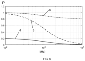
- FIG. 5 is a schematic diagram of the third gain function according to some embodiments of this specification; and FIG. 6 is a schematic diagram of the third gain function according to other embodiments of this specification.
- an x-axis is a signal-to-noise ratio SNR
- a y-axis is the third gain coefficient y 3 .
- a curve 1 is a relationship between the third gain coefficient y 3 and the signal-to-noise ratio SNR when a frequency point i corresponding to a frequency unit is i 1 .
- a curve 2 is a relationship between the third gain coefficient y 3 and the signal-to-noise ratio SNR when a frequency point i corresponding to a frequency unit is i 2
- a curve 3 is a relationship between the third gain coefficient y 3 and the signal-to-noise ratio SNR when a frequency point i corresponding to a frequency unit is i 3 .
- the third gain coefficient y 3 is in negative correlation with the frequency point i corresponding to the frequency unit, and is in positive correlation with the signal-to-noise ratio SNR.
- an x-axis is a frequency point i corresponding to a frequency unit
- a y-axis is the third gain coefficient y 3
- a curve 4 is a relationship between the third gain coefficient y 3 and the frequency point i corresponding to the frequency unit when a signal-to-noise ratio SNR is SNR 1
- a curve 5 is a relationship between the third gain coefficient y 3 and the frequency point i corresponding to the frequency unit when a signal-to-noise ratio SNR is SNR 2
- a curve 6 is a relationship between the third gain coefficient y 3 and the frequency point i corresponding to the frequency unit when a signal-to-noise ratio SNR is SNR 3 .
- the third gain coefficient y 3 is in negative correlation with the frequency point i corresponding to the frequency unit, and is in positive correlation with the signal-to-noise ratio SNR.
- FIG. 3 to FIG. 6 are exemplary descriptions only, and the gain function may also be another monotonic function.
- a person skilled in the art should understand that all monotonic functions satisfying a requirement may be the gain function described in this specification and all fall within the protection scope of this specification.
- Step S142 may include one of the following cases:
- Step S140 may further include: S144: performing gain processing on the to-be-processed audio signal based on the gain coefficient, to obtain the target audio signal.
- the system 100 may perform the gain processing on each of the plurality of frequency units based on a plurality of gain coefficients corresponding to the plurality of frequency units, to obtain the target audio signal.
- the system 100 may multiply a gain coefficient corresponding to each frequency unit by strength of an audio signal corresponding to the current frequency unit, so as to obtain a gain audio signal corresponding to the current frequency unit; and superimpose the plurality of gain audio signals corresponding to the plurality of frequency units, to obtain the target audio signal.
- the target audio signal more or all audio signals corresponding to a frequency including more valid audio signals are preserved, and more or all audio signals corresponding to a frequency including less valid audio signals and including more noise signals are discarded.
- gain processing can be performed on each frequency unit using audio signals frequencies as units based on a feature(s) of each frequency, so that more audio signals corresponding to frequency units including more valid audio signals are preserved, while less audio signals corresponding to frequency units including fewer valid audio signals are preserved. In this way, fidelity and intelligibility of an audio signal are improved while quality of the audio signal is improved and noise is reduced.
- the system 100 and the method P100 may be used to perform denoising processing on an audio signal that has been processed by using a first audio denoising algorithm, or may be used to perform denoising processing on an audio signal that has not been processed by using the first audio denoising algorithm.
- the system 100 and the method P100 may also be combined with the first audio denoising algorithm, to jointly perform denoising processing on the audio signal.
- the electronic device 200 may first obtain the target audio signal by performing denoising processing on the audio signal by using a method P100, and then perform denoising processing on the target audio signal by using the first audio denoising algorithm.
- the electronic device 200 may first perform denoising processing on the to-be-processed audio signal by using the first audio denoising algorithm, and then perform denoising processing, by using a method P100, on the audio signal that is processed by using the first audio denoising algorithm, to obtain the target audio signal.
- the non-transitory storage medium stores at least one set of executable instructions for audio denoising, and when the executable instructions are executed by a processor, the executable instructions instruct the processor to implement steps of the audio denoising method P100 described in this specification.
- each aspect of this specification may be further implemented in a form of a program product, where the program product includes program code.
- the program product operates on the electronic device 200, the program code is used to enable the electronic device 200 to perform steps of audio denoising described in this specification.
- the program product for implementing the aforementioned method may use a portable compact disc read-only memory (CD-ROM) including program code, and can operate on the electronic device 200.
- CD-ROM portable compact disc read-only memory
- a readable storage medium may be any tangible medium containing or storing a program, and the program may be used by or in connection with an instruction execution system (for example, the processor 220).
- the program product may use any combination of one or more readable media.
- the readable medium may be a readable signal medium or a readable storage medium.
- the readable storage medium may be but is not limited to an electronic, magnetic, optical, electromagnetic, infrared, or semiconductor system, apparatus, or device, or any combination thereof.
- the readable storage medium include: an electrical connection having one or more conducting wires, a portable diskette, a hard disk, a random access memory (RAM), a read-only memory (ROM), an erasable programmable read-only memory (EPROM or Flash memory), an optical fiber, a portable compact disc read-only memory (CD-ROM), an optical storage device, a magnetic storage device, or any appropriate combination thereof.
- the computer-readable storage medium may include a data signal propagated in a baseband or as a part of a carrier, where the data signal carries readable program code. The propagated data signal may be in a plurality of forms, including but not limited to an electromagnetic signal, an optical signal, or any appropriate combination thereof.
- the readable storage medium may be any readable medium other than the readable storage medium.
- the readable medium may send, propagate, or transmit a program used by or in connection with an instruction execution system, apparatus, or device.
- the program code contained in the readable storage medium may be transmitted by using any appropriate medium, including, but not limited to: wireless, wired, an optical cable, RF, or the like, or any appropriate combination thereof. Any combination of one or more programming languages may be used to compile program code for performing operations in this specification.
- the programming languages include object-oriented programming languages such as Java and C++, and further include conventional procedural programming languages such as the "C" language or a similar programming language.
- the program code may be fully executed on the electronic device 200, partially executed on the electronic device 200, executed as an independent software package, partially executed on the electronic device 200 and partially executed on a remote computing device, or fully executed on a remote computing device.
Landscapes
- Engineering & Computer Science (AREA)
- Physics & Mathematics (AREA)
- Acoustics & Sound (AREA)
- Signal Processing (AREA)
- Multimedia (AREA)
- Health & Medical Sciences (AREA)
- Quality & Reliability (AREA)
- Computational Linguistics (AREA)
- Audiology, Speech & Language Pathology (AREA)
- Human Computer Interaction (AREA)
- General Health & Medical Sciences (AREA)
- Otolaryngology (AREA)
- Circuit For Audible Band Transducer (AREA)
Abstract
Description
- This specification relates to the audio signal processing field, and in particular, to an audio denoising method and system.
- In many life scenarios, we are surrounded by noise, and we need to perform voice enhancement to have better auditory experience. The voice enhancement may also be referred to as noise suppression, which means to reduce or suppress noise to some extent, so as to improve the quality, intelligibility, and the like of a voice surrounded by noise. In a conventional method, generally, a capture device of a signal source is an air-conduction component, that is, an air-conduction microphone. In a high noise scenario, a valid audio signal captured by the air-conduction microphone is almost completely surrounded by noise.
- Currently, a bone-conduction microphone is used on an electronic product such as a headphone, and there are more and more applications using bone-conduction microphones to receive voice signals. More and more electronic devices combine an air-conduction microphone and a bone-conduction microphone having different features, the air-conduction microphone is used to pick an external audio signal, the bone-conduction microphone is used to pick a vibration signal of a sound generation part, and voice enhancement processing and fusion are performed on the picked signals. Different from an air-conduction microphone, a bone-conduction component may directly pick a vibration signal of a sound generation part, which can reduce the impact of ambient noise to some extent. In solutions combining an air-conduction microphone and a bone-conduction microphone, there is a solution with a plurality of air-conduction microphones and one bone-conduction microphone, and there is also a solution with one air-conduction microphone and one bone-conduction microphone. In a high noise scenario, voice quality of a single air-conduction microphone is poor, and voice quality of a bone-conduction microphone is also polluted by external noise to some extent.
- Currently, for noise suppression, there are various denoising algorithms, for example, a single-microphone denoising algorithm, such as a spectral subtraction method or a Wiener filtering method, and a microphone array denoising algorithm, such as a fixed beamforming method or an adaptive beamforming method. In a high noise scenario, single-microphone denoising becomes very difficult, and a conventional denoising algorithm such as spectral subtraction or Wiener filtering has a very limited effect on increasing a signal-to-noise ratio (denoising strength is insufficient); and some improved algorithms increase denoising strength but cause great voice distortion, and there is an obvious noise residue in a high-frequency part. How to further improve, on a basis of the conventional audio denoising algorithm, voice quality of an air-conduction microphone signal, a bone-conduction microphone signal, or an audio signal obtained after fusion of an air-conduction microphone signal and a bone-conduction microphone signal, is a problem that urgently needs to be resolved.
- Therefore, a new audio denoising method and system is needed for preserving voice fidelity and intelligibility while filtering noise and increasing a signal-to-noise ratio in a high noise scenario.
- This specification provides a new audio denoising method and system to preserve voice fidelity and intelligibility while filtering noise and increasing a signal-to-noise ratio in a high noise scenario.
- According to a first aspect, this specification provides an audio denoising method, including: obtaining at least one modulation parameter related to a frequency of a to-be-processed audio signal; and performing gain processing on the to-be-processed audio signal based on a gain coefficient corresponding to the at least one modulation parameter to obtain a target audio signal.
- According to a second aspect, this specification further provides an audio denoising system, including: at least one storage medium, storing at least one set of instruction for audio denoising; and at least one processor in communication with the at least one storage medium, when the audio denoising system operates, the at least one processor reads the at least one instruction set, and performs the audio denoising method based on an instruction of the at least one set of instruction according to the first aspect.
- As can be known from the foregoing technical solutions, in the audio denoising method and system provided in this specification, optimization processing may be further performed on an audio signal on a basis of a conventional audio denoising method by using a frequency as a unit. In the method and system, gain processing may be performed on the audio signal based on at least one of a plurality of frequency units of the audio signal or signal-to-noise ratios corresponding to the plurality of frequency units. In the method and system, a gain coefficient(s) may be generated based on the plurality of frequency units of the audio signal and the signal-to-noise ratios corresponding to the plurality of frequency units, and gain processing is performed on the audio signal by using the gain coefficient. The higher the signal-to-noise ratio, the larger the gain coefficient. The higher the frequency, the smaller the gain coefficient. In the method and system, the audio signal may be further optimized on a basis of the conventional audio denoising method. More audio signals corresponding to frequencies including more valid audio signals are preserved, while less audio signals corresponding to frequencies including fewer valid audio signals are preserved. In this way, voice fidelity and intelligibility are preserved while noise is filtered, and the signal-to-noise ratio is increased.
- Other functions of the audio denoising method and system provided in this specification are partially listed in the following descriptions. Based on the descriptions, content described in the following digits and examples would be obvious for a person of ordinary skill in the art. Creative aspects of the audio denoising method and system provided in this specification may be fully explained by practicing or using the method, apparatus, and a combination thereof in the following detailed examples.
- To clearly describe the technical solutions in the embodiments of this specification, the following briefly describes the accompanying drawings required for describing the embodiments. Apparently, the accompanying drawings in the following description show merely some embodiments of this specification, and a person of ordinary skill in the art may derive other drawings from these accompanying drawings without creative efforts.
-
FIG. 1 is a schematic device diagram of an audio denoising system according to some embodiments of this specification; -
FIG. 2 is a flowchart of an audio denoising method according to some embodiments of this specification; -
FIG. 3 is a schematic diagram of a first gain function according to some embodiments of this specification; -
FIG. 4 is a schematic diagram of a second gain function according to some embodiments of this specification; -
FIG. 5 is a schematic diagram of a third gain function according to some embodiments of this specification; and -
FIG. 6 is a schematic diagram of a third gain function according to some embodiments of this specification. - The following description provides specific application scenarios and requirements of this specification, to enable a person skilled in the art to make and use the contents of this specification. For a person skilled in the art, various partial modifications to the disclosed embodiments are obvious, and general principles defined herein can be applied to other embodiments and applications without departing from the spirit and scope of this specification. Therefore, this specification is not limited to the illustrated embodiments, but is to be accorded the widest scope consistent with the claims.
- The terms used herein are only intended to describe specific exemplary embodiments and are not restrictive. For example, unless otherwise clearly indicated in a context, the terms "a", "an", and "the" in singular forms may also include plural forms. When used in this specification, the terms "comprising", "including", and/or "containing" indicate presence of associated integers, steps, operations, elements, and/or components. However, this does not exclude presence of one or more other features, integers, steps, operations, elements, components, and/or groups or addition of other features, integers, steps, operations, elements, components, and/or groups to the system/method.
- In view of the following description, these features and other features of this specification, operations and functions of related elements of structures, and combinations of components and economics of manufacturing thereof can be significantly improved. With reference to the drawings, all of these form a part of this specification. However, it should be clearly understood that the drawings are only for illustration and description purposes and are not intended to limit the scope of this specification. It should also be understood that the drawings are not drawn to scale.
- A flowchart used in this specification shows operations implemented by the system according to some embodiments of this specification. It should be clearly understood that operations in the flowchart may not be implemented sequentially. Conversely, the operations may be implemented in a reverse sequence or simultaneously. In addition, one or more other operations may be added to the flowchart, and one or more operations may be removed from the flowchart.
- When performing denoising on audio signals, some denoising algorithms preserve audio signals on all frequencies almost evenly. In other words, the denoising algorithms perform same denoising processing on audio signals of different frequencies. Therefore, proportions of signals preserved on different frequencies of audio signals processed by using the denoising algorithms are consistent. However, in audio signals carrying noise, valid audio signals included in different frequencies are different. For example, a valid audio signal (that is, a human voiceprint) included in a low-frequency part in an audio signal carrying a noise signal is higher than a valid audio signal included in a high-frequency part. When performing denoising processing on the audio signals, the denoising algorithms do not consider a frequency factor of the audio signals, resulting in roughly consistent denoising strength across different frequencies. For example, when a high-strength denoising algorithm is used to perform denoising processing on an audio signal carrying a noise signal, while a noise signal in a high-frequency part is reduced, a valid audio signal in a low-frequency part is discarded, thus causes voice distortion. When a low-strength denoising algorithm is used to perform denoising processing on an audio signal carrying a noise signal, there is an obvious noise residue in a high-frequency part, resulting in poor audio denoising effect.
- The valid audio signal may be an important audio signal carried by the audio signal. The noise signal may be an audio signal other than the valid audio signal. For example, during a voice call, the valid audio signal may be a human voice signal when a user of the call speaks, and the noise signal may be ambient noise, for example, sound of a vehicle, sound of whistling, etc. When special sound is captured, for example, when sound of chirping is captured, the valid audio signal may be an audio signal of chirping, and the noise signal may be sound of a wind, sound of water, or the like. For ease of presentation, a voice call is taken as an example for description in the following descriptions, where the valid audio signal is a human voice signal when a user of the call speaks, and the noise signal may be ambient noise.
- It should be noted that the noise signal and the valid audio signal are both signals obtained by using an estimation algorithm. The noise signal may be estimated by using a noise estimation algorithm. The valid audio signal may be obtained through estimation by subtracting the noise signal from an original audio signal.
- In other audio denoising methods and systems provided in the following descriptions of this specification, different gain processing may be performed on audio signals of different frequencies based on parameters related to the frequencies of the audio signals. In other words, in the audio denoising methods and systems provided in this specification, gain processing can be performed on each frequency separately using frequencies of audio signals as units based on a feature of each frequency, so that proportions of audio denoising on all frequencies are uneven, so that more audio signals corresponding to frequency parts including more valid audio signals are preserved, while less audio signals corresponding to frequency parts including fewer valid audio signals are preserved. In this way, fidelity and intelligibility of an audio signal are improved while quality of the audio signal is improved and noise is reduced.
- The fidelity may be a similarity between an audio signal output by a device and an audio signal received by the device. The higher fidelity, the higher the similarity between the audio signal output by the device and the audio signal received by the device. The intelligibility may also be voice articulation. The higher the voice articulation, the higher the intelligibility.
-
FIG. 1 is a schematic device diagram of an audio denoising system 100 (hereinafter referred to as the system 100). Thesystem 100 may be applied to anelectronic device 200. - In some embodiments, the
electronic device 200 may be a wireless headphone, a wired headphone, or an intelligent wearable device, for example, a device having a voice capture function and a voice playing function such as smart glasses, a smart helmet, or a smart watch. Theelectronic device 200 may also be a mobile device, a tablet computer, a notebook computer, a built-in apparatus of a motor vehicle, or the like, or any combination thereof. In some embodiments, the mobile device may include a smart household device, a smart mobile device, a virtual reality device, an augmented reality device, or the like, or any combination thereof. For example, the smart mobile device may include a mobile phone, a personal digital assistant, a game device, a navigation device, an ultra-mobile personal computer (Ultra-mobile Personal Computer, UMPC), or the like, or any combination thereof. In some embodiments, the smart household device may include a smart TV, a desktop computer, or the like, or any combination thereof. In some embodiments, the virtual reality device or the augmented reality device may include a virtual reality helmet, virtual reality glasses, a virtual reality patch, an augmented reality helmet, augmented reality glasses, an augmented reality patch, or the like, or any combination thereof. In some embodiments, the built-in apparatus of the motor vehicle may include a vehicle-mounted computer, a vehicle-mounted television, or the like. - The
electronic device 200 may store data or an instruction(s) for performing an audio denoising method described in this specification, and may execute the data and/or the instruction(s). Theelectronic device 200 may receive a to-be-processed audio signal, and execute data or an instruction of the audio denoising method described in this specification, to perform audio denoising processing on the to-be-processed audio signal, and generate a target audio signal. The audio denoising method is described in other parts of this specification. For example, the audio denoising method is described in the descriptions ofFIG. 2 to FIG. 6 . - The to-be-processed audio signal includes at least a valid audio signal. The to-be-processed audio signal may also include a noise signal. The to-be-processed audio signal may be an audio signal locally stored by the
electronic device 200, or may be an audio signal output by an audio capture device of theelectronic device 200, or may be an audio signal sent by another device to theelectronic device 200, or the like. The audio capture device may be integrated with theelectronic device 200, or may be an externally connected device that is communicatively connected to theelectronic device 200. - As shown in
FIG. 1 , theelectronic device 200 may include at least onestorage medium 230 and at least oneprocessor 220. In some embodiments, theelectronic device 200 may further include acommunications port 250 and aninternal communications bus 210. In addition, theelectronic device 200 may further include an I/O component 260. In some embodiments, theelectronic device 200 may further include amicrophone module 240. - The
internal communications bus 210 may connect different system components, including thestorage medium 230, theprocessor 220, and themicrophone module 240. - The I/
O component 260 supports inputting/outputting between theelectronic device 200 and another component. For example, theelectronic device 200 may obtain the to-be-processed audio signal by using the I/O component 260. - The
communications port 250 is used by theelectronic device 200 to perform external data communication. For example, theelectronic device 200 may also obtain the to-be-processed audio signal by using thecommunications port 250. - The at least one
storage medium 230 may include a data storage device. The data storage apparatus may be a non-transitory storage medium, or may be a transitory storage medium. For example, the data storage apparatus may include one or more of amagnetic disk 232, a read-only memory (ROM) 234, or a random access memory (RAM) 236. Thestorage medium 230 further includes at least one instruction set stored in the data storage apparatus, where the instruction set is used for audio denoising. The instruction is computer program code, where the computer program code may include a program, a routine, an object, a component, a data structure, a process, a module, or the like for performing the audio denoising method provided in this specification. The at least onestorage medium 230 may also store the to-be-processed audio signal. The at least onestorage medium 230 may further prestore a gain function, where the gain function is described in detail in subsequent descriptions. - The at least one
processor 220 may be communicatively connected to the at least onestorage medium 230 by using theinternal communications bus 210. The communication connection is a connection in any form and capable of directly or indirectly receiving information. The at least oneprocessor 220 is configured to execute the at least one instruction set. When thesystem 100 operates, the at least oneprocessor 220 reads the at least one instruction set, and performs, based on an instruction of the at least one instruction set, the audio denoising method provided by this specification. Theprocessor 220 may perform all steps included in the audio denoising method. Theprocessor 220 may be in a form of one or more processors. In some embodiments, theprocessor 220 may include one or more hardware processors, for example, a microcontroller, a microprocessor, a reduced instruction set computer (RISC), an application-specific integrated circuit (ASIC), an application-specific instruction set processor (ASIP), a central processing unit (CPU), a graphics processing unit (GPU), a physical processing unit (PPU), a microcontroller unit, a digital signal processor (DSP), a field programmable gate array (FPGA), an advanced RISC machine (ARM), a programmable logic device (PLD), or any other types of circuit or processor that can implement one or more functions, and the like, or any combination thereof. For illustration purpose only, only oneprocessor 220 in theelectronic device 200 is described in this specification. However, it should be noted that theelectronic device 200 in this specification may further include a plurality of processors. Therefore, operations and/or method steps disclosed in this specification may be performed by one processor in this specification, or may be performed jointly by a plurality of processors. For example, if theprocessor 220 of theelectronic device 200 in this specification performs step A and step B, it should be understood that step A and step B may also be performed jointly or separately by two different processors 220 (for example, the first processor performs step A, and the second processor performs step B, or the first processor and the second processor jointly perform step A and step B). - In some embodiments, the
electronic device 200 may further include themicrophone module 240. Themicrophone module 240 may be an audio capture device of theelectronic device 200. Themicrophone module 240 may be configured to obtain a local audio signal, and output a microphone signal, that is, an electrical signal carrying audio information. The to-be-processed audio signal may be the microphone signal output by themicrophone module 240. Themicrophone module 240 may be communicatively connected to the at least oneprocessor 220 and the at least onestorage medium 230. When the to-be-processed audio signal is a microphone signal, and thesystem 100 operates, the at least oneprocessor 220 may read the at least one instruction set, obtain the microphone signal based on the instruction of the at least one instruction set, and perform the audio denoising method provided in this specification. Themicrophone module 240 may be integrated with theelectronic device 200, or may be a device externally connected to theelectronic device 200. - The
microphone module 240 may be configured to obtain a local audio signal, and output a microphone signal, that is, electrical signal carrying audio information. Themicrophone module 240 may be an out-of-ear microphone module or may be an in-ear microphone module. For example, themicrophone module 240 may be a microphone disposed out of an auditory canal, or may be a microphone disposed in an auditory canal. Themicrophone module 240 may be a first-type microphone, and may be a microphone directly capturing a human body vibration signal, for example, a bone-conduction microphone. Themicrophone module 240 may also be a second-type microphone, and may be a microphone directly capturing an air vibration signal, for example, an air-conduction microphone. Themicrophone module 240 may also be a combination of a first-type microphone and a second-type microphone. Certainly, themicrophone module 240 may also be another type of microphone. For example, themicrophone module 240 may be an optical microphone, or may be a microphone for receiving an electromyographic signal. For ease of presentation, in the following descriptions of the present disclosure, the bone-conduction microphone is used as an example of the first-type microphone, and the air-conduction microphone is used as an example of the second-type microphone for description. - The bone-conduction microphone may include a vibration sensor, for example, an optical vibration sensor or an acceleration sensor. The vibration sensor may capture a mechanical vibration signal (for example, a signal generated by a vibration generated by the skin or bones when a user speaks), and convert the mechanical vibration signal into an electrical signal. Herein, the mechanical vibration signal mainly refers to a vibration propagated by a solid. The bone-conduction microphone captures, by touching the skin or bones of the user by using the vibration sensor or a vibration component connected to the vibration sensor, a vibration signal generated by the bones or skin when the user makes a sound, and converts the vibration signal into an electrical signal. In some embodiments, the vibration sensor may be a device that is sensitive to a mechanical vibration but insensitive to an air vibration (that is, a capability of responding to the mechanical vibration by the vibration sensor exceeds a capability of responding to the air vibration by the vibration sensor). Because the bone-conduction microphone can directly pick a vibration signal of a sound generation part, the bone-conduction microphone can reduce impact of ambient noise.
- The air-conduction microphone captures an air vibration signal caused when a user makes a sound, and converts the air vibration signal into an electrical signal. The air-conduction microphone may be a separate air-conduction microphone, or may be a microphone array including two or more air-conduction microphones. The microphone array may be a beamforming microphone array or another similar microphone array. Sound coming from different directions or positions may be captured by using the microphone array.
- The first-type microphone may output a first audio signal. The second-type microphone may output a second audio signal.
- The
system 100 may receive the to-be-processed audio signal, and perform the audio denoising method described in this specification to perform audio denoising processing on the to-be-processed audio signal, generate and output the target audio signal. The to-be-processed audio signal may be an original audio signal that is not denoised by using an audio denoising algorithm, or may be an audio signal obtained after the original audio signal is processed by using a first audio denoising algorithm. The original audio signal may be the first audio signal, or may be the second audio signal, or may be an audio signal obtained through fusion of the first audio signal and the second audio signal. - For example, the to-be-processed audio signal may be an audio signal obtained after the first audio signal is processed by using the first audio denoising method, or may be an audio signal obtained after the second audio signal is processed by using the first audio denoising method, or may be an audio signal obtained after the audio signal obtained through fusion of the first audio signal and the second audio signal is processed by using the first audio denoising method.
- The first audio denoising algorithm may be a conventional audio denoising algorithm, for example, at least one of: a spectral subtraction method, a Wiener filtering method, an MMSE algorithm, or an MMSE-based improved algorithm, or any combination thereof. The target audio signal obtained after denoising processing performed by the
system 100 preserves more audio signals including more valid audio signals. Therefore, voice quality of the target audio signal can be improved, and voice fidelity and intelligibility can be improved. -
FIG. 2 is a flowchart of an audio denoising method P100 according to an embodiment of this specification. As shown inFIG. 2 , the method P100 may include the following step performed by at least one processor 220:
S120: obtaining a modulation parameter(s) related to a frequency of a to-be-processed audio signal. - As described above, in the method P100 and
system 100, audio denoising may be performed on the to-be-processed audio signal by using the frequency as a unit. In a frequency domain, a frequency interval of an audio may be divided into a plurality of frequency units, that is, frequency intervals with preset bandwidths. Alternatively, a plurality of frequency units may be represented by a plurality of frequencies. In the method P100 andsystem 100, gain processing may be performed on an audio signal corresponding to each frequency unit or each frequency band unit in the frequency interval separately, so that more audio signals corresponding to frequency parts (for example, frequency intervals with high signal-to-noise ratios SNRs) including more valid audio signals are preserved, while less audio signals corresponding to frequency parts (for example, frequency intervals with a low signal-to-noise ratios SNRs) including fewer valid audio signals are preserved. In this way, quality of the audio signal is improved. For example, for a to-be-processed voice audio, if a signal-to-noise ratio of a low-frequency part of the to-be-processed voice audio is high (that is, a valid audio signal is strong but a noise signal is weak) but a signal-to-noise ratio of a high-frequency part is low (that is, the valid audio signal is weak but the noise signal is strong), in the method P100 andsystem 100, the high-frequency part in the audio may be suppressed while the low-frequency part is amplified to improve quality of the entire audio. As a result, articulation of the valid audio signal in the audio signal is improved while noise in the audio signal is reduced. - Therefore, the modulation parameter may be a parameter related to a frequency in the frequency domain. For example, the modulation parameter may be a frequency unit, or may be a parameter related to a frequency unit, and its amplitude may change with a change in frequency. For example, the modulation parameter may be a signal-to-noise ratio (SNR), and the signal-to-noise ratio may be a parameter related to the frequency. Therefore, the modulation parameter is a parameter that can reflect an amount of the valid audio signal included in the to-be-processed audio signal.
- The modulation parameter may be a parameter related to the frequency of the to-be-processed audio signal. In the frequency domain, the frequency is a continuous parameter. For ease of calculation, the frequency of the to-be-processed audio signal may be divided into a plurality of frequency units. Each frequency unit may include a frequency interval with a preset bandwidth. Each frequency unit may also be represented by a frequency point. The frequency point may be an intermediate frequency value of a frequency interval in which a current frequency unit is located, or an average frequency value, or the like. Bandwidths of frequency intervals of different frequency units may be the same or may be different. Distances between adjacent frequency points may be the same or may be different. The
system 100 may determine a bandwidth of the frequency interval of each frequency unit based on a feature of a noise signal of the to-be-processed audio signal. For example, when the noise signal is stable, the bandwidth of the frequency interval of the frequency unit may be larger. When the noise signal is unstable, the bandwidth of the frequency interval of the frequency unit may be smaller. For example, the frequency point may be 10 Hz, 100 Hz, 150 Hz, 200 Hz, 1000 Hz, or 10000 Hz. - For ease of description, we can approximately divide the frequency of the to-be-processed audio signal into a low frequency, an intermediate frequency, and a high frequency. The low-frequency region may include frequencies in [0, a], where a is a frequency upper limit of the low-frequency region. For example, a may be any frequency between 400 and 800. For example, a may be 400, 450, 500, 550, 600, 650, 700, 750, or 800. The intermediate-frequency region may include frequencies in (a, b], where b is a frequency upper limit of the intermediate-frequency region. For example, b may be any frequency between 2000 and 4000. For example, b may be 2000, 2500, 3000, 3500, or 4000. The high-frequency region may include frequencies in [b, c], where c is a frequency upper limit of the high-frequency region. The frequency upper limit c of the high-frequency region may be any frequency greater than 4000.
- Specifically, the modulation parameter may be the plurality of frequency units of the to-be-processed audio signal, or may be a plurality of signal-to-noise ratios corresponding to the plurality of frequency units, or may be the plurality of frequency units and a plurality of signal-to-noise ratios corresponding to the plurality of frequency units. Using a voice call as an example, there are more valid audio signals in a low frequency than that of in a high frequency. The signal-to-noise ratio may be a proportion of valid audio signals to noise signals in the to-be-processed audio signal. If a signal-to-noise ratio corresponding to the frequency is higher, it indicates that a proportion of valid audio signals in the current frequency is higher.
- Alternatively, the modulation parameter may be any parameter related to the frequency. For example, the modulation parameter may be strength of a plurality of valid audio signals corresponding to the plurality of frequency units, or may be strength of a plurality of noise signals corresponding to the plurality of frequency units. The plurality of frequency units may be the plurality of frequency points. For ease of presentation, in the following descriptions, it is assumed that the modulation parameter is at least one of: the plurality of frequency units of the to-be-processed audio signal or the plurality of signal-to-noise ratios corresponding to the plurality of frequency units.
- To obtain the modulation parameter of the to-be-processed audio signal, the
system 100 may first divide the to-be-processed audio signal into frames. A frame is a basic unit forming an audio signal. During data processing of an audio signal, frames are generally used as basic units for calculation. The to-be-processed audio signal may include one or more audio frames. An audio frame includes an audio signal of a preset duration. An audio signal in each audio frame is stable. Adjacent audio frames may partially overlap. The preset duration may be 20-50 milliseconds, for example, 20 milliseconds, 25 milliseconds, 30 milliseconds, 40 milliseconds, or 50 milliseconds. Certainly, the preset duration may also be longer or shorter. Durations of different audio frames may be the same or may be different. - It should be noted that a plurality of frequency units in different audio frames may be the same or may be different.
- To obtain a spectrogram of the to-be-processed audio signal, the
system 100 may perform Fourier transform on the audio frame, to obtain signal distribution of each frequency in the audio frame. The signal distribution of each frequency may be the strength of audio signals corresponding to each frequency in the audio frame. - The
system 100 may obtain, based on the signal distribution of each frequency in each audio frame in the to-be-processed audio signal, the modulation parameter corresponding to each audio frame in the to-be-processed audio signal, that is, a plurality of frequency units in each audio frame in the to-be-processed audio signal and a plurality of signal-to-noise ratios corresponding to the plurality of frequency units. Each frequency in the plurality of frequency units corresponds to one signal-to-noise ratio of the plurality of signal-to-noise ratios. Signal-to-noise ratios corresponding to audio signals of different frequencies may be different. - It should be noted that when performing audio denoising processing on the to-be-processed audio signal, the
system 100 may perform the audio denoising processing on all audio frames, or may perform the audio denoising processing on some audio frames. - When the modulation parameter includes the plurality of signal-to-noise ratios, step S120 may include: obtaining an initial modulation parameter corresponding to the frequency of the to-be-processed audio signal; and performing smoothing processing on a value of the initial modulation parameter by using the frequency as a variable, and obtaining the modulation parameter. The initial modulation parameter corresponding to the to-be-processed audio signal may be a plurality of initial signal-to-noise ratios corresponding to the plurality of frequency units in each audio frame in the to-be-processed audio signal. The initial signal-to-noise ratio may be a signal-to-noise ratio corresponding to each frequency unit. Initial signal-to-noise ratios corresponding to audio signals of different frequency units may be different. Initial signal-to-noise ratios corresponding to audio signals of adjacent frequency units may also be different, and may even vary greatly.
- To enable smooth transitions of the plurality of signal-to-noise ratios corresponding to the plurality of frequency units in each audio frame in the to-be-processed audio signal, the
system 100 may perform the smoothing processing on the value of the initial modulation parameter by using the frequency as a variable, to obtain the modulation parameter. As described above, the initial modulation parameter may be the plurality of initial signal-to-noise ratios corresponding to the plurality of frequency units. - The smoothing processing may use any appropriate processing manner. For example, the smoothing processing may be performing feature fusion processing on an initial signal-to-noise ratio corresponding to each of the plurality of frequency units and an initial signal-to-noise ratio corresponding to at least one frequency unit near a current frequency unit, to obtain a signal-to-noise ratio corresponding to the current frequency. As described above, each frequency unit may be represented by a frequency point. For example, the feature fusion may be averaging the signal-to-noise ratios. Performing the smoothing processing on a signal-to-noise ratio corresponding to a frequency unit may be averaging signal-to-noise ratios of several frequency units before the frequency unit and several frequency units after the frequency unit, and may be represented by the following formula:

system 100 on the to-be-processed audio signal. - S140: performing gain processing on the to-be-processed audio signal based on a gain coefficient(s) corresponding to the modulation parameter, to obtain a target audio signal. Specifically, step S140 may include:
S142: generating, based on the modulation parameter and a preset gain function, the gain coefficient corresponding to the modulation parameter. - As described above, the
system 100 may perform denoising processing on the to-be-processed audio signal based on the frequency of the to-be-processed audio signal. Specifically, thesystem 100 may perform gain processing, by using the plurality of frequency units of the to-be-processed audio signal as units, on audio signals corresponding to the plurality of frequency units of the to-be-processed audio signal. - The
system 100 may perform gain processing on the to-be-processed audio signal by using the preset gain function. The gain function may be a correlation function between the gain coefficient and the modulation parameter. - The gain coefficient may be any number greater than 0. The gain coefficient may be any number from 0 to 1, including 0 and 1. When more valid audio signals are included in the current frequency unit of the to-be-processed audio signal, noise is lower, and a gain coefficient corresponding to the current frequency unit is larger, so that more valid audio signals are preserved. When fewer valid audio signals are included in the current frequency unit of the to-be-processed audio signal, a noise signal is higher, and a gain coefficient corresponding to the current frequency unit is smaller, so that the noise signal is reduced. In some embodiments, the gain coefficient may also be any number greater than 1. When a lot of valid audio signals and little noise are included in some frequency units in the to-be-processed audio signal, the gain coefficient corresponding to the current frequency unit may be a coefficient greater than 1, so that the valid audio signals are enhanced.
- As described above, the valid audio signal included in the to-be-processed audio signal may be reflected by using the modulation parameter. Therefore, the gain function may be a monotonic function related to the modulation parameter. For example, if there are more valid audio signals and less noise signals, the gain coefficient is larger; or if there are fewer valid audio signals and more noise signals, the gain coefficient is smaller.
- The gain function may be any monotonic function. For example, the gain function may be a monotonic function based on a sigmoid function, or the gain function may be a monotonic function based on a log function, or the gain function may be a monotonic function based on a tan function. For ease of description, in the following descriptions, it is assumed that the gain function is a monotonic function based on a sigmoid function. The gain function may be a linear monotonic function or a non-linear correlation function.
- When the modulation parameter is the plurality of signal-to-noise ratios corresponding to the plurality of frequency units, higher signal-to-noise ratio corresponding to the frequency unit means more valid audio signals are included in the current frequency unit, and in this case, the gain coefficient corresponding to the current frequency unit is larger, so that more signals corresponding to the current frequency unit are preserved; Lower signal-to-noise ratio corresponding to the frequency unit means fewer valid audio signals and more noise signals are included in the current frequency unit, and in this case, the gain coefficient corresponding to the current frequency unit is smaller, so that more signals corresponding to the current frequency unit are discarded. Therefore, the gain coefficient is in positive correlation with the plurality of signal-to-noise ratios.
- When the modulation parameter is the plurality of frequency units, more audio signals is discarded in a high-frequency part, that is, a gain coefficient corresponding to the high-frequency part is smaller; and more audio signals is preserved in a low-frequency part, that is, a gain coefficient corresponding to the low-frequency part is larger, and a better audio denoising effect can be achieved. Therefore, when a frequency point corresponding to the frequency unit is lower, the gain coefficient corresponding to the current frequency unit is larger, so that more signals corresponding to the current frequency are preserved; or when a frequency point corresponding to the frequency unit is higher, the gain coefficient corresponding to the current frequency unit is smaller, so that more signals corresponding to the current frequency are discarded. Therefore, when the valid audio signal is a human voice signal, the gain coefficient is in negative correlation with the plurality of frequency units.
- The gain function may be any one of a first gain function, a second gain function, or a third gain function. The first gain function may be a correlation between a first gain coefficient and a frequency, where the first gain coefficient is in negative correlation with the frequency. The second gain function may be a correlation between a second gain coefficient and a signal-to-noise ratio, where the second gain coefficient is in positive correlation with the signal-to-noise ratio. The third gain function may be a correlation between a third gain coefficient and a frequency and a signal-to-noise ratio, where the third gain coefficient is in negative correlation with the frequency and is in positive correlation with the signal-to-noise ratio. The gain coefficient may include one of the first gain coefficient, the second gain coefficient, and the third gain coefficient.
- When the modulation parameter is the plurality of frequency units, the gain function may be the first gain function, and the gain coefficient may be the first gain coefficient. When the modulation parameter is the plurality of signal-to-noise ratios corresponding to the plurality of frequency units, the gain function may be the second gain function, and the gain coefficient may be the second gain coefficient. When the modulation parameter is the plurality of frequency units and the plurality of signal-to-noise ratios corresponding to the plurality of frequency units, the gain function may be the third gain function, and the gain coefficient may be the third gain coefficient.
- As an example, assuming the gain function is a monotonic function based on a sigmoid function, the first gain function may be represented by the following formula:

FIG. 3 is a schematic diagram of the first gain function according to some embodiments of this specification. As shown inFIG. 3 , an x-axis is a frequency point i corresponding to a frequency unit, and a y-axis is the first gain coefficient y 1. The first gain coefficient y 1 is in negative correlation with the frequency point i corresponding to the frequency unit. - As an example, assuming the gain function is a monotonic function based on a sigmoid function, the second gain function may be represented by the following formula:

FIG. 4 is a schematic diagram of the second gain function according to some embodiments of this specification. As shown inFIG. 4 , an x-axis is a signal-to-noise ratio SNR, and a y-axis is the second gain coefficient y 2. The second gain coefficient y 2 is in positive correlation with the signal-to-noise ratio SNR. - As an example, assuming that the gain function is a monotonic function based on a sigmoid function, the third gain function may be represented by the following formula:

FIG. 5 is a schematic diagram of the third gain function according to some embodiments of this specification; andFIG. 6 is a schematic diagram of the third gain function according to other embodiments of this specification. - As shown in
FIG. 5 , an x-axis is a signal-to-noise ratio SNR, and a y-axis is the third gain coefficient y 3. Acurve 1 is a relationship between the third gain coefficient y 3 and the signal-to-noise ratio SNR when a frequency point i corresponding to a frequency unit is i 1. Acurve 2 is a relationship between the third gain coefficient y 3 and the signal-to-noise ratio SNR when a frequency point i corresponding to a frequency unit is i 2 Acurve 3 is a relationship between the third gain coefficient y 3 and the signal-to-noise ratio SNR when a frequency point i corresponding to a frequency unit is i 3. i 1 < i 2 < i3 . As shown inFIG. 5 , the third gain coefficient y 3 is in negative correlation with the frequency point i corresponding to the frequency unit, and is in positive correlation with the signal-to-noise ratio SNR. - As shown in
FIG. 6 , an x-axis is a frequency point i corresponding to a frequency unit, and a y-axis is the third gain coefficient y 3. Acurve 4 is a relationship between the third gain coefficient y 3 and the frequency point i corresponding to the frequency unit when a signal-to-noise ratio SNR is SNR1. Acurve 5 is a relationship between the third gain coefficient y 3 and the frequency point i corresponding to the frequency unit when a signal-to-noise ratio SNR is SNR2. Acurve 6 is a relationship between the third gain coefficient y 3 and the frequency point i corresponding to the frequency unit when a signal-to-noise ratio SNR is SNR3. SNR1 < SNR2 < SNR 3. As shown inFIG. 6 , the third gain coefficient y 3 is in negative correlation with the frequency point i corresponding to the frequency unit, and is in positive correlation with the signal-to-noise ratio SNR. - The third gain coefficient may be further represented by the following formula, to achieve an audio denoising effect of higher precision:

- It should be noted that
FIG. 3 to FIG. 6 are exemplary descriptions only, and the gain function may also be another monotonic function. A person skilled in the art should understand that all monotonic functions satisfying a requirement may be the gain function described in this specification and all fall within the protection scope of this specification. - Step S142 may include one of the following cases:
- when the modulation parameter is the plurality of frequency units, generating, based on the plurality of frequency units and the first gain function, a plurality of first gain coefficients corresponding to the plurality of frequency units;
- when the modulation parameter is the plurality of signal-to-noise ratios corresponding to the plurality of frequency units, generating, based on the plurality of signal-to-noise ratios and the second gain function, a plurality of second gain coefficients corresponding to the plurality of frequency units; and
- when the modulation parameter is the plurality of frequency units and the plurality of signal-to-noise ratios corresponding to the plurality of frequency units, generating, based on the plurality of signal-to-noise ratios, the plurality of frequency units, and the third gain function, a plurality of third gain coefficients corresponding to the plurality of frequency units.
- Step S140 may further include:
S144: performing gain processing on the to-be-processed audio signal based on the gain coefficient, to obtain the target audio signal. Specifically, thesystem 100 may perform the gain processing on each of the plurality of frequency units based on a plurality of gain coefficients corresponding to the plurality of frequency units, to obtain the target audio signal. Specifically, thesystem 100 may multiply a gain coefficient corresponding to each frequency unit by strength of an audio signal corresponding to the current frequency unit, so as to obtain a gain audio signal corresponding to the current frequency unit; and superimpose the plurality of gain audio signals corresponding to the plurality of frequency units, to obtain the target audio signal. - In the target audio signal, more or all audio signals corresponding to a frequency including more valid audio signals are preserved, and more or all audio signals corresponding to a frequency including less valid audio signals and including more noise signals are discarded.
- In summary, in the audio denoising method P100 and
system 100 provided in this specification, gain processing can be performed on each frequency unit using audio signals frequencies as units based on a feature(s) of each frequency, so that more audio signals corresponding to frequency units including more valid audio signals are preserved, while less audio signals corresponding to frequency units including fewer valid audio signals are preserved. In this way, fidelity and intelligibility of an audio signal are improved while quality of the audio signal is improved and noise is reduced. - It should be noted that the
system 100 and the method P100 may be used to perform denoising processing on an audio signal that has been processed by using a first audio denoising algorithm, or may be used to perform denoising processing on an audio signal that has not been processed by using the first audio denoising algorithm. Thesystem 100 and the method P100 may also be combined with the first audio denoising algorithm, to jointly perform denoising processing on the audio signal. Specifically, theelectronic device 200 may first obtain the target audio signal by performing denoising processing on the audio signal by using a method P100, and then perform denoising processing on the target audio signal by using the first audio denoising algorithm. Alternatively, theelectronic device 200 may first perform denoising processing on the to-be-processed audio signal by using the first audio denoising algorithm, and then perform denoising processing, by using a method P100, on the audio signal that is processed by using the first audio denoising algorithm, to obtain the target audio signal. - Another aspect of this specification provides a non-transitory storage medium. The non-transitory storage medium stores at least one set of executable instructions for audio denoising, and when the executable instructions are executed by a processor, the executable instructions instruct the processor to implement steps of the audio denoising method P100 described in this specification. In some possible implementations, each aspect of this specification may be further implemented in a form of a program product, where the program product includes program code. When the program product operates on the
electronic device 200, the program code is used to enable theelectronic device 200 to perform steps of audio denoising described in this specification. The program product for implementing the aforementioned method may use a portable compact disc read-only memory (CD-ROM) including program code, and can operate on theelectronic device 200. However, the program product in this specification is not limited thereto. In this specification, a readable storage medium may be any tangible medium containing or storing a program, and the program may be used by or in connection with an instruction execution system (for example, the processor 220). The program product may use any combination of one or more readable media. The readable medium may be a readable signal medium or a readable storage medium. For example, the readable storage medium may be but is not limited to an electronic, magnetic, optical, electromagnetic, infrared, or semiconductor system, apparatus, or device, or any combination thereof. More specific examples of the readable storage medium include: an electrical connection having one or more conducting wires, a portable diskette, a hard disk, a random access memory (RAM), a read-only memory (ROM), an erasable programmable read-only memory (EPROM or Flash memory), an optical fiber, a portable compact disc read-only memory (CD-ROM), an optical storage device, a magnetic storage device, or any appropriate combination thereof. The computer-readable storage medium may include a data signal propagated in a baseband or as a part of a carrier, where the data signal carries readable program code. The propagated data signal may be in a plurality of forms, including but not limited to an electromagnetic signal, an optical signal, or any appropriate combination thereof. Alternatively, the readable storage medium may be any readable medium other than the readable storage medium. The readable medium may send, propagate, or transmit a program used by or in connection with an instruction execution system, apparatus, or device. The program code contained in the readable storage medium may be transmitted by using any appropriate medium, including, but not limited to: wireless, wired, an optical cable, RF, or the like, or any appropriate combination thereof. Any combination of one or more programming languages may be used to compile program code for performing operations in this specification. The programming languages include object-oriented programming languages such as Java and C++, and further include conventional procedural programming languages such as the "C" language or a similar programming language. The program code may be fully executed on theelectronic device 200, partially executed on theelectronic device 200, executed as an independent software package, partially executed on theelectronic device 200 and partially executed on a remote computing device, or fully executed on a remote computing device. - Specific embodiments in this specification are described above. Other embodiments fall within the scope of the appended claims. In some cases, actions or steps described in the claims may be performed in a sequence different from those of these embodiments, and the expected results can still be achieved. In addition, illustration of specific sequences or continuous sequences is not necessarily required for the processes described in the drawings to achieve the expected results. In some implementations, multi-task processing and parallel processing are also allowed or may be advantageous.
- In summary, after reading details of the present disclosure, a person skilled in the art would understand that the details in the present disclosure may be presented by using examples only, and may not be restrictive. A person skilled in the art would understand that this specification covers various reasonable changes, improvements, and modifications to the embodiments, although this is not specified herein. These changes, improvements, and modifications are intended to be proposed in this specification and are within the spirit and scope of the exemplary embodiments of this specification.
- In addition, some terms in this specification are used to describe the embodiments of this specification. For example, "one embodiment", "an embodiment", and/or "some embodiments" mean/means that a specific feature, structure, or characteristic described with reference to the embodiment(s) may be included in at least one embodiment of this specification. Therefore, it should be emphasized and should be understood that two or more references to "an embodiment" or "one embodiment" or "alternative embodiment" in various parts of this specification do not necessarily all refer to the same embodiment. In addition, specific features, structures, or characteristics may be appropriately combined in one or more embodiments of this specification.
- It should be understood that in the foregoing description of the embodiments of this specification, to help understand one feature, for the purpose of simplifying this specification, various features in this specification are combined in a single embodiment, single drawing, or description thereof. However, this does not mean that the combination of these features is necessary. It is entirely possible for a person skilled in the art to extract some of the features as a separate embodiment for understanding when reading this specification. In other words, an embodiment in this specification may also be understood as an integration of a plurality of sub-embodiments. It is also true when content of each sub-embodiment is less than all features of a single embodiment disclosed above.
- Each patent, patent application, patent application publication, and other materials cited herein, such as articles, books, instructions, publications, documents, and other materials can be incorporated herein by reference. All content used for all purposes, except any prosecution document history related to the content, any identical prosecution document history that may be inconsistent or conflict with this document, or any identical prosecution document history that may have restrictive impact on the broadest scope of the claims, is associated with this document now or later. For example, if there is any inconsistency or conflict between descriptions, definitions, and/or use of terms associated with any material contained therein and descriptions, definitions, and/or use of terms related to this document, the terms in this document shall prevail.
- Finally, it should be understood that the implementation solutions of this application disclosed in this specification are descriptions of principles of the implementation solutions of this specification. Other modified embodiments also fall within the scope of this specification. Therefore, the embodiments disclosed in this specification are merely exemplary and not restrictive. A person skilled in the art may use alternative configurations according to the embodiments of this specification to implement the application in this specification. Therefore, the embodiments of this specification are not limited to those precisely described in this application.
Claims (17)
- An audio denoising method, characterized by comprising:obtaining at least one modulation parameter related to a frequency of a to-be-processed audio signal; andperforming gain processing on the to-be-processed audio signal based on a gain coefficient corresponding to the at least one modulation parameter to obtain a target audio signal.
- The audio denoising method according to claim 1, characterized in that the modulation parameter comprises at least one of:
a plurality of frequency units of the to-be-processed audio signal, or a plurality of signal-to-noise ratios corresponding to the plurality of frequency units. - The audio denoising method according to claim 2, characterized in that the to-be-processed audio signal comprises an audio signal obtained after an original audio signal is processed by using a first audio denoising algorithm.
- The audio denoising method according to claim 3, characterized in that the first audio denoising algorithm comprises at least one of: a spectral subtraction method, a Wiener filtering method, an MMSE algorithm, and an MMSE-based improved algorithm.
- The audio denoising method according to claim 3, characterized in that the original audio signal comprises one of: a first audio signal output by a first-type microphone, a second audio signal output by a second-type microphone, or an audio signal obtained after fusion of the first audio signal and the second audio signal.
- The audio denoising method according to claim 2, characterized in that the performing of the gain processing on the to-be-processed audio signal based on a gain coefficient corresponding to the at least one modulation parameter to obtain the target audio signal comprises:generating, based on the at least one modulation parameter and a preset gain function, the at least one gain coefficient corresponding to the at least one modulation parameter, characterized in that the gain function comprises a correlation between the at least one gain coefficient and the at least one modulation parameter; andperforming the gain processing on the to-be-processed audio signal based on the gain coefficient to obtain the target audio signal.
- The audio denoising method according to claim 6, characterized in that the gain function is a monotonic function.
- The audio denoising method according to claim 7, characterized in that the at least one gain coefficient is in a positive correlation with the plurality of signal-to-noise ratios.
- The audio denoising method according to claim 8, characterized in that the at least one gain coefficient is in a negative correlation with the plurality of frequency units.
- The audio denoising method according to claim 9, characterized in that:the at least one modulation parameter is the plurality of frequency units;the gain function is a first gain function and comprises a correlation between at least one first gain coefficient and the frequency;the at least one gain coefficient is the at least one first gain coefficient; andthe generating, based on the at least one modulation parameter and the preset gain function, of the at least one gain coefficient corresponding to the at least one modulation parameter comprises:
generating, based on the plurality of frequency units and the first gain function, a plurality of first gain coefficients corresponding to the plurality of frequency units. - The audio denoising method according to claim 9, characterized in that:the at least one modulation parameter is the plurality of signal-to-noise ratios corresponding to the plurality of frequency units;the gain function is a second gain function and comprises a correlation between at least one second gain coefficient and at least one signal-to-noise ratio;the at least one gain coefficient is the at least one second gain coefficient; andthe generating, based on the at least one modulation parameter and the preset gain function, of the at least one gain coefficient corresponding to the at least one modulation parameter comprises:
generating, based on the plurality of signal-to-noise ratios and the second gain function, a plurality of second gain coefficients corresponding to the plurality of frequency units. - The audio denoising method according to claim 9, characterized in that:the at least one modulation parameter is the plurality of frequency units and the plurality of signal-to-noise ratios corresponding to the plurality of frequency units;the gain function is a third gain function and comprises a correlation between at least one third gain coefficient and the frequency and the at least one signal-to-noise ratio;the at least one gain coefficient is the at least one third gain coefficient; andthe generating, based on the at least one modulation parameter and the preset gain function, of the at least one gain coefficient corresponding to the at least one modulation parameter comprises:
generating, based on the plurality of signal-to-noise ratios, the plurality of frequency units, and the third gain function, a plurality of third gain coefficients corresponding to the plurality of frequency units. - The audio denoising method according to claim 7, characterized in that the gain function is a function based on a sigmoid function.
- The audio denoising method according to claim 6, characterized in that the performing of the gain processing on the to-be-processed audio signal based on the at least one gain coefficient, to obtain the target audio signal comprises:
performing the gain processing on each of the plurality of frequency units based on the at least one gain coefficient, to obtain the target audio signal. - The audio denoising method according to claim 2, characterized in that the obtaining of the at least one modulation parameter related to the frequency of a to-be-processed audio signal comprises:obtaining at least one initial modulation parameter corresponding to the frequency of the to-be-processed audio signal; andperforming smoothing processing on a value of the at least one initial modulation parameter by using the frequency as a variable to obtain the modulation parameter.
- The audio denoising method according to claim 15, characterized in that the performing smoothing processing on the value of the at least one initial modulation parameter by using the frequency as the variable comprises:
performing feature fusion processing on an initial signal-to-noise ratio corresponding to each of the plurality of frequency units and an initial signal-to-noise ratio corresponding to at least one frequency unit near a current frequency unit, to obtain a signal-to-noise ratio corresponding to the current frequency. - An audio denoising system, characterized by comprising:at least one storage medium, storing at least one set of instruction for audio denoising; andat least one processor in communication with the at least one storage medium, characterized in thatwhen the audio denoising system operates, the at least one processor reads the at least one instruction set, and performs the audio denoising method based on an instruction of the at least one set of instruction according to any one of claims 1 to 16.
Applications Claiming Priority (1)
| Application Number | Priority Date | Filing Date | Title |
|---|---|---|---|
| PCT/CN2020/140214 WO2022140927A1 (en) | 2020-12-28 | 2020-12-28 | Audio noise reduction method and system |
Publications (2)
| Publication Number | Publication Date |
|---|---|
| EP4270392A1 true EP4270392A1 (en) | 2023-11-01 |
| EP4270392A4 EP4270392A4 (en) | 2024-07-24 |
Family
ID=82259003
Family Applications (1)
| Application Number | Title | Priority Date | Filing Date |
|---|---|---|---|
| EP20967279.9A Pending EP4270392A4 (en) | 2020-12-28 | 2020-12-28 | METHOD AND SYSTEM FOR AUDIO NOISE REDUCTION |
Country Status (6)
| Country | Link |
|---|---|
| US (1) | US12335698B2 (en) |
| EP (1) | EP4270392A4 (en) |
| JP (1) | JP2023552363A (en) |
| KR (1) | KR20230098284A (en) |
| CN (1) | CN116964663A (en) |
| WO (1) | WO2022140927A1 (en) |
Family Cites Families (22)
| Publication number | Priority date | Publication date | Assignee | Title |
|---|---|---|---|---|
| JP2000047697A (en) * | 1998-07-30 | 2000-02-18 | Nec Eng Ltd | Noise canceler |
| US6766292B1 (en) * | 2000-03-28 | 2004-07-20 | Tellabs Operations, Inc. | Relative noise ratio weighting techniques for adaptive noise cancellation |
| JP5025485B2 (en) | 2005-10-31 | 2012-09-12 | パナソニック株式会社 | Stereo encoding apparatus and stereo signal prediction method |
| CN102016994B (en) * | 2008-07-29 | 2013-07-17 | Lg电子株式会社 | An apparatus for processing an audio signal and method thereof |
| EP2151822B8 (en) * | 2008-08-05 | 2018-10-24 | Fraunhofer-Gesellschaft zur Förderung der angewandten Forschung e.V. | Apparatus and method for processing an audio signal for speech enhancement using a feature extraction |
| US8571231B2 (en) * | 2009-10-01 | 2013-10-29 | Qualcomm Incorporated | Suppressing noise in an audio signal |
| JP5548529B2 (en) * | 2010-06-10 | 2014-07-16 | キヤノン株式会社 | Audio signal processing apparatus and photographing apparatus |
| CN104103278A (en) | 2013-04-02 | 2014-10-15 | 北京千橡网景科技发展有限公司 | Real time voice denoising method and device |
| JP6379839B2 (en) | 2014-08-11 | 2018-08-29 | 沖電気工業株式会社 | Noise suppression device, method and program |
| KR101630155B1 (en) | 2014-09-11 | 2016-06-15 | 현대자동차주식회사 | An apparatus to eliminate a noise of sound, a method for eliminating a noise of a sound, a sound recognition apparatus using the same and a vehicle equipped with the sound recognition apparatus |
| DK3252766T3 (en) * | 2016-05-30 | 2021-09-06 | Oticon As | AUDIO PROCESSING DEVICE AND METHOD FOR ESTIMATING THE SIGNAL-TO-NOISE RATIO FOR AN AUDIO SIGNAL |
| TWI609366B (en) | 2016-10-21 | 2017-12-21 | 宏碁股份有限公司 | Electronic device and frequency dividing filter gain optimization method thereof |
| US10224053B2 (en) | 2017-03-24 | 2019-03-05 | Hyundai Motor Company | Audio signal quality enhancement based on quantitative SNR analysis and adaptive Wiener filtering |
| WO2019112468A1 (en) * | 2017-12-08 | 2019-06-13 | Huawei Technologies Co., Ltd. | Multi-microphone noise reduction method, apparatus and terminal device |
| CN107910011B (en) | 2017-12-28 | 2021-05-04 | 科大讯飞股份有限公司 | A kind of speech noise reduction method, device, server and storage medium |
| CN108847208B (en) * | 2018-05-04 | 2020-11-27 | 歌尔科技有限公司 | Noise reduction processing method and device and earphone |
| US10636434B1 (en) * | 2018-09-28 | 2020-04-28 | Apple Inc. | Joint spatial echo and noise suppression with adaptive suppression criteria |
| CN109686347B (en) | 2018-11-30 | 2021-04-23 | 北京达佳互联信息技术有限公司 | Sound effect processing method, sound effect processing device, electronic equipment and readable medium |
| CN110634497B (en) * | 2019-10-28 | 2022-02-18 | 普联技术有限公司 | Noise reduction method and device, terminal equipment and storage medium |
| CN111131947B (en) | 2019-12-05 | 2022-08-09 | 小鸟创新(北京)科技有限公司 | Earphone signal processing method and system and earphone |
| CN111554321B (en) * | 2020-04-20 | 2023-12-05 | 北京达佳互联信息技术有限公司 | Noise reduction model training method, device, electronic equipment and storage medium |
| CN111627455B (en) * | 2020-06-03 | 2025-05-09 | 腾讯科技(深圳)有限公司 | A method and device for reducing noise in audio data, and a computer-readable storage medium |
-
2020
- 2020-12-28 EP EP20967279.9A patent/EP4270392A4/en active Pending
- 2020-12-28 KR KR1020237018120A patent/KR20230098284A/en not_active Ceased
- 2020-12-28 CN CN202080103925.2A patent/CN116964663A/en active Pending
- 2020-12-28 WO PCT/CN2020/140214 patent/WO2022140927A1/en not_active Ceased
- 2020-12-28 JP JP2023533790A patent/JP2023552363A/en active Pending
-
2023
- 2023-04-14 US US18/135,101 patent/US12335698B2/en active Active
Also Published As
| Publication number | Publication date |
|---|---|
| US12335698B2 (en) | 2025-06-17 |
| JP2023552363A (en) | 2023-12-15 |
| WO2022140927A1 (en) | 2022-07-07 |
| KR20230098284A (en) | 2023-07-03 |
| US20230262390A1 (en) | 2023-08-17 |
| EP4270392A4 (en) | 2024-07-24 |
| CN116964663A (en) | 2023-10-27 |
Similar Documents
| Publication | Publication Date | Title |
|---|---|---|
| US12142290B2 (en) | Audio signal generation method and system | |
| CN109493877B (en) | Voice enhancement method and device of hearing aid device | |
| EP3413589A1 (en) | A microphone system and a hearing device comprising a microphone system | |
| CN102074246B (en) | Dual-microphone based speech enhancement device and method | |
| CN113539285B (en) | Audio signal noise reduction method, electronic device and storage medium | |
| CN108766456B (en) | Voice processing method and device | |
| CN110556125B (en) | Feature extraction method and device based on voice signal and computer storage medium | |
| CN104103278A (en) | Real time voice denoising method and device | |
| CN111063366A (en) | Method and device for reducing noise, electronic equipment and readable storage medium | |
| CN110379439A (en) | A kind of method and relevant apparatus of audio processing | |
| US12067999B2 (en) | Audio signal processing method and system for echo suppression | |
| WO2022036761A1 (en) | Deep learning noise reduction method that fuses in-ear microphone and on-ear microphone, and device | |
| CN110992967A (en) | Voice signal processing method and device, hearing aid and storage medium | |
| CN114694668A (en) | Method and system for generating audio | |
| CN101587712B (en) | Directional speech enhancement method based on small microphone array | |
| CN112669869A (en) | Noise suppression method, device, apparatus and storage medium | |
| US8233650B2 (en) | Multi-stage estimation method for noise reduction and hearing apparatus | |
| CN103824563A (en) | Hearing aid denoising device and method based on module multiplexing | |
| CN114093380B (en) | Voice enhancement method, electronic equipment, chip system and readable storage medium | |
| US12335698B2 (en) | Audio denoising method and system | |
| CN117912485A (en) | Voice band extension method, noise reduction audio device and storage medium | |
| CN114694673A (en) | Method and system for audio noise reduction | |
| CN113421582B (en) | Microphone voice enhancement method and device, terminal and storage medium | |
| CN112785997B (en) | Noise estimation method and device, electronic equipment and readable storage medium | |
| WO2026065095A1 (en) | Audio processing method and device |
Legal Events
| Date | Code | Title | Description |
|---|---|---|---|
| STAA | Information on the status of an ep patent application or granted ep patent |
Free format text: STATUS: THE INTERNATIONAL PUBLICATION HAS BEEN MADE |
|
| PUAI | Public reference made under article 153(3) epc to a published international application that has entered the european phase |
Free format text: ORIGINAL CODE: 0009012 |
|
| STAA | Information on the status of an ep patent application or granted ep patent |
Free format text: STATUS: REQUEST FOR EXAMINATION WAS MADE |
|
| 17P | Request for examination filed |
Effective date: 20230615 |
|
| AK | Designated contracting states |
Kind code of ref document: A1 Designated state(s): AL AT BE BG CH CY CZ DE DK EE ES FI FR GB GR HR HU IE IS IT LI LT LU LV MC MK MT NL NO PL PT RO RS SE SI SK SM TR |
|
| DAV | Request for validation of the european patent (deleted) | ||
| DAX | Request for extension of the european patent (deleted) | ||
| A4 | Supplementary search report drawn up and despatched |
Effective date: 20240621 |
|
| RIC1 | Information provided on ipc code assigned before grant |
Ipc: H04R 1/46 20060101ALI20240617BHEP Ipc: G10L 21/02 20130101AFI20240617BHEP |
|
| STAA | Information on the status of an ep patent application or granted ep patent |
Free format text: STATUS: EXAMINATION IS IN PROGRESS |
|
| 17Q | First examination report despatched |
Effective date: 20251106 |