EP4270390A2 - Adaptive comfort noise parameter determination - Google Patents
Adaptive comfort noise parameter determination Download PDFInfo
- Publication number
- EP4270390A2 EP4270390A2 EP23182371.7A EP23182371A EP4270390A2 EP 4270390 A2 EP4270390 A2 EP 4270390A2 EP 23182371 A EP23182371 A EP 23182371A EP 4270390 A2 EP4270390 A2 EP 4270390A2
- Authority
- EP
- European Patent Office
- Prior art keywords
- inactive segment
- curr
- prev
- segment
- parameter
- Prior art date
- Legal status (The legal status is an assumption and is not a legal conclusion. Google has not performed a legal analysis and makes no representation as to the accuracy of the status listed.)
- Granted
Links
Images




Classifications
-
- G—PHYSICS
- G10—MUSICAL INSTRUMENTS; ACOUSTICS
- G10L—SPEECH ANALYSIS TECHNIQUES OR SPEECH SYNTHESIS; SPEECH RECOGNITION; SPEECH OR VOICE PROCESSING TECHNIQUES; SPEECH OR AUDIO CODING OR DECODING
- G10L19/00—Speech or audio signals analysis-synthesis techniques for redundancy reduction, e.g. in vocoders; Coding or decoding of speech or audio signals, using source filter models or psychoacoustic analysis
- G10L19/008—Multichannel audio signal coding or decoding using interchannel correlation to reduce redundancy, e.g. joint-stereo, intensity-coding or matrixing
-
- G—PHYSICS
- G10—MUSICAL INSTRUMENTS; ACOUSTICS
- G10L—SPEECH ANALYSIS TECHNIQUES OR SPEECH SYNTHESIS; SPEECH RECOGNITION; SPEECH OR VOICE PROCESSING TECHNIQUES; SPEECH OR AUDIO CODING OR DECODING
- G10L19/00—Speech or audio signals analysis-synthesis techniques for redundancy reduction, e.g. in vocoders; Coding or decoding of speech or audio signals, using source filter models or psychoacoustic analysis
- G10L19/012—Comfort noise or silence coding
-
- G—PHYSICS
- G10—MUSICAL INSTRUMENTS; ACOUSTICS
- G10L—SPEECH ANALYSIS TECHNIQUES OR SPEECH SYNTHESIS; SPEECH RECOGNITION; SPEECH OR VOICE PROCESSING TECHNIQUES; SPEECH OR AUDIO CODING OR DECODING
- G10L25/00—Speech or voice analysis techniques not restricted to a single one of groups G10L15/00 - G10L21/00
- G10L25/78—Detection of presence or absence of voice signals
- G10L2025/783—Detection of presence or absence of voice signals based on threshold decision
- G10L2025/786—Adaptive threshold
-
- G—PHYSICS
- G10—MUSICAL INSTRUMENTS; ACOUSTICS
- G10L—SPEECH ANALYSIS TECHNIQUES OR SPEECH SYNTHESIS; SPEECH RECOGNITION; SPEECH OR VOICE PROCESSING TECHNIQUES; SPEECH OR AUDIO CODING OR DECODING
- G10L25/00—Speech or voice analysis techniques not restricted to a single one of groups G10L15/00 - G10L21/00
- G10L25/78—Detection of presence or absence of voice signals
- G10L25/84—Detection of presence or absence of voice signals for discriminating voice from noise
Definitions
- CN comfort noise
- DTX Discontinuous Transmission
- a DTX scheme further relies on a Voice Activity Detector (VAD), which indicates to the system whether to use the active signal encoding methods in or the low rate background noise encoding in active respectively inactive segments.
- VAD Voice Activity Detector
- the system may be generalized to discriminate between other source types by using a (Generic) Sound Activity Detector (GSAD or SAD), which not only discriminates speech from background noise but also may detect music or other signal types which are deemed relevant.
- GSAD Generic Sound Activity Detector
- Communication services may be further enhanced by supporting stereo or multichannel audio transmission.
- a DTX/CNG system also needs to consider the spatial characteristics of the signal in order to provide a pleasant sounding comfort noise.
- a common CN generation method e.g. used in all 3GPP speech codecs, is to transmit information on the energy and spectral shape of the background noise in the speech pauses. This can be done using significantly less number of bits than the regular coding of speech segments.
- the CN is generated by creating a pseudo-random signal and then shaping the spectrum of the signal with a filter based on information received from the transmitting side. The signal generation and spectral shaping can be done in the time or the frequency domain.
- the capacity gain comes from the fact that the CN is encoded with fewer bits than the regular encoding. Part of this saving in bits comes from the fact that the CN parameters are normally sent less frequently than the regular coding parameters. This normally works well since the background noise character is not changing as fast as e.g. a speech signal.
- the encoded CN parameters are often referred to as a "SID frame" where SID stands for Silence Descriptor.
- a typical case is that the CN parameters are sent every 8th speech encoder frame (one speech encoder frame is typically 20 ms) and these are then used in the receiver until the next set of CN parameters is received (see FIG. 2 ).
- One solution to avoid undesired fluctuations in the CN is to sample the CN parameters during all 8 speech encoder frames and then transmit an average or some other way to base the parameters on all 8 frames as shown in FIG. 3 .
- a CN parameter is typically determined based on signal characteristics over the period between two consecutive CN parameter transmissions while in an inactive segment.
- the first frame in each inactive segment is however treated differently: here the CN parameter is based on signal characteristics of the first frame of inactive coding, typically a first SID frame, and any hangover frames, and also signal characteristics of the last-sent SID frame and any inactive frames after that in the end of the previous inactive segment. Weighting factors are applied such that the weight for the data from the previous inactive segment is decreasing as a function of the length of the active segment in-between. The older the previous data is, the less weight it gets.
- Embodiments of the present invention improve the stability of CN generated in a decoder, while being agile enough to follow changes in the input signal.
- a method for generating a comfort noise (CN) side-gain parameter includes receiving an audio input, wherein the audio input comprises multiple channels; detecting, with a Voice Activity Detector (VAD), a current inactive segment in the audio input; as a result of detecting, with the VAD, the current inactive segment in the audio input, calculating a CN side-gain parameter SG(b) for a frequency band b; and providing the CN side-gain parameter SG(b) to a decoder.
- the CN side-gain parameter SG(b) is calculated based at least in part on the current inactive segment and a previous inactive segment.
- a method for generating comfort noise includes receiving a CN side-gain parameter SG(b) for a frequency band b generated according to any one of the embodiments of the first aspect, and generating comfort noise based on the CN parameter SG(b).
- a node for generating a comfort noise (CN) side-gain parameter includes a receiving unit configured to receive an audio input, wherein the audio input comprises multiple channels; a detecting unit configured to detect, with a Voice Activity Detector (VAD), a current inactive segment in the audio input; a calculating unit configured to calculate, as a result of detecting, with the VAD, the current inactive segment in the audio input, a CN side-gain parameter SG(b) for a frequency band b; and a providing unit configured to provide the CN side-gain parameter SG(b) to a decoder.
- the CN side-gain parameter SG(b) is calculated based at least in part on the current inactive segment and a previous inactive segment
- nF represents the number of frames in the active segment between the current segment and the previous inactive segment, corresponding to T active .
- a decoder for generating comfort noise CN
- the node includes a receiving unit configured to receive a CN side-gain parameter SG(b) for a frequency band b generated according to any one of the embodiments of the first aspect; and a generating unit configured to generate comfort noise based on the CN parameter SG(b).
- a computer program comprising instructions which when executed by processing circuity of a node causes the node to perform the method of any one of the embodiments of the first aspect.
- a carrier containing the computer program of any of the embodiments of the fifth aspect, wherein the carrier is one of an electronic signal, an optical signal, a radio signal, and a computer readable storage medium.
- the background noise characteristics will be stable over time. In these cases it will work well to use the CN parameters from the previous inactive segment as a starting point in the current inactive segment, instead of relying on a more unstable sample taken in a shorter period of time in the beginning of the current inactive segment.
- FIG. 1 illustrates a DTX system 100 according to some embodiments.
- DTX system 100 an audio signal is received as input.
- System 100 includes three modules, a Voice Activity Detector (VAD), a Speech/Audio Coder, and a CNG Coder.
- VAD Voice Activity Detector
- Speech/Audio Coder e.g. detecting active or inactive segments, such as segments of active speech or no speech. If there is speech, the speech/audio coder will code the audio signal and send the result to be transmitted. If there is no speech, the CNG Coder will generate comfort noise parameters to be transmitted.
- CN used f T active T curr T prev CN curr CN prev
- the weighting between previous and current CN parameter averages may be based only on the length of the active segment, i.e. on T active .
- T active the length of the active segment
- the additional variables referenced have the following meanings:
- An averaging of the parameter CN is done by using both an average taken from the current inactive segment and an average taken from the previous segment. These two values are then combined with weighting factors based on a weighting function that depends, in some embodiments, on the length of the active segment between the current and the previous inactive segment such that less weight is put on the previous average if the active segment is long and more weight if it is short.
- the weights are additionally adapted based on T prev and T curr . This may, for example, mean that a larger weight is given the previous CN parameters because the T curr period is too short to give a stable estimate of the long-term signal characteristics that can be represented by the CNG system.
- the additional variables referenced have the following meanings:
- An established method for encoding a multi-channel (e.g. stereo) signal is to create a mix-down (or downmix) signal of the input signals, e.g. mono in the case of stereo input signals and determine additional parameters that are encoded and transmitted with the encoded downmix signal to be utilized for an up-mix at the decoder.
- a mono signal may be encoded and generated as CN and stereo parameters will then be used create a stereo signal from the mono CN signal.
- the stereo parameters are typically controlling the stereo image in terms of e.g. sound source localization and stereo width.
- the variation in the stereo parameters may be faster than the variation in the mono CN parameters.
- Side gains may be determined in broad-band from time domain signals, or in frequency sub-bands obtained from downmix and side signals represented in a transform domain, e.g. the Discrete Fourier Transform (DFT) or Modified Discrete Cosine Transform (MDCT) domains, or by some other filterbank representation.
- DFT Discrete Fourier Transform
- MDCT Modified Discrete Cosine Transform
- FIG. 6 shows a schematic picture of how the side-gain averaging is done, according to an embodiment. Note that the combined weighted average is typically only used in the first frame of each interactive segment.
- N curr and N prev can differ from each other and from time to time.
- N prev will in addition to the frames of the last transmitted CN parameters also include the inactive frames (so-called no-data frames) between the last CN parameter transmission and the first active frames.
- An active frame can of course occur anytime, so this number will vary.
- N curr will include the number of frames in the hangover period plus the first inactive frame which may also vary if the length of the hangover period is adaptive.
- N curr may not only include consecutive hangover frames, but may in general represent the number of frames included in the determination of current CN parameters.
- LPC Linear Predictive Coding
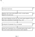
- FIG. 7 illustrates a process 700 for generating a comfort noise (CN) parameter.
- CN comfort noise
- the method includes receiving an audio input (step 702).
- the method further includes detecting, with a Voice Activity Detector (VAD), a current inactive segment in the audio input (step 704).
- VAD Voice Activity Detector
- the method further includes, as a result of detecting, with the VAD, the current inactive segment in the audio input, calculating a CN parameter CN used (step 706).
- the method further includes providing the CN parameter CN used to a decoder (step 708).
- the CN parameter CN used is calculated based at least in part on the current inactive segment and a previous inactive segment (step 710).
- the functions g 1 ( ⁇ ) represents an average over the time period T curr and the function g 2 (.) represents an average over the time period T prev .
- W 1 ( ⁇ ) 0 ⁇ W 1 ( ⁇ ) ⁇ 1 and 0 ⁇ 1 - W 2 ( ⁇ ) ⁇ 1
- W 1 ( ⁇ ) converges to 1
- W 2 ( ⁇ ) converges to 0 in the limit.
- N curr represents the number of frames corresponding to the time-interval parameter T curr
- N prev represents the number of frames corresponding to the time-interval parameter T prev
- W 1 ( T active ) and W 2 (T active ) are weighting functions.
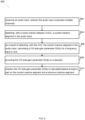
- FIG. 8 illustrates a process 800 for generating a comfort noise (CN) side-gain parameter.
- the method includes receiving an audio input, wherein the audio input comprises multiple channels (step 802).
- the method further includes detecting, with a Voice Activity Detector (VAD), a current inactive segment in the audio input (step 804).
- VAD Voice Activity Detector
- the method further includes, as a result of detecting, with the VAD, the current inactive segment in the audio input, calculating a CN side-gain parameter SG(b) for a frequency band b (step 806).
- the method further includes providing the CN side-gain parameter SG(b) to a decoder (step 808).
- the CN side-gain parameter SG(b) is calculated based at least in part on the current inactive segment and a previous inactive segment (step 810).
- SG curr ( b,i ) represents a side gain value for frequency band b and frame i in current inactive segment
- SG prev (b,j) represents a side gain value for frequency band b and frame j in previous inactive segment
- N curr represents the number of frames in the sum from current inactive segment
- N prev represents the number of frames in the sum from previous inactive segment
- W(nF) represents a weighting function
- nF represents the number of frames in the active segment between the current segment and the previous inactive segment, corresponding to T active .
- FIG. 9 illustrates a processes 900 and 910 for generating comfort noise (CN).
- the process includes a step of receiving a CN parameter CN used where the CN parameter CN used is generated according to any one of the embodiments herein disclosed for generating a comfort noise (CN) parameter (step 902) and a step of generating comfort noise based on the CN parameter CN used (step 904).
- CN comfort noise
- the process includes a step of receiving a CN side-gain parameter SG(b) for a frequency band b where the CN side-gain parameter SG(b) for a frequency band b is generated according to any one of the embodiments herein disclosed for generating a CN side-gain parameter SG(b) for a frequency band b (step 912) and a step of generating comfort noise based on the CN parameter SG(b) (step 914).
- FIG. 10 is a diagram showing functional units of node 1002 (e.g. an encoder/decoder) for generating a comfort noise (CN) parameter, according to an embodiment.
- node 1002 e.g. an encoder/decoder
- CN comfort noise
- the node 1002 includes a receiving unit 1004 configured to receive an audio input; a detecting unit 1006 configured to detect, with a Voice Activity Detector (VAD), a current inactive segment in the audio input; a calculating unit 1008 configured to calculate, as a result of detecting, with the VAD, the current inactive segment in the audio input, a CN parameter CN used ; and a providing unit 1010 configured to provide the CN parameter CN used to a decoder.
- the CN parameter CN used is calculated by the calculating unit based at least in part on the current inactive segment and a previous inactive segment.
- FIG. 11 is a diagram showing functional units of node 1002 (e.g. an encoder/decoder) for generating a comfort noise (CN) side gain parameter, according to an embodiment.
- Node 1002 includes a receiving unit 1104 configured to receive a CN parameter CN used according to any one of the embodiments discussed with regard to FIG. 7 and a generating unit 1104 configured to generate comfort noise based on the CN parameter CN used .
- the receiving unit is configured to receive a CN side-gain parameter SG(b) for a frequency band b according to any one of the embodiments discussed with regard to FIG. 8 and the generating unit is configured to generate comfort noise based on the CN parameter SG(b).
- FIG. 12 is a block diagram of node 1002 (e.g., an encoder/decoder) for generating a comfort noise (CN) parameter and/or for generating comfort noise (CN), according to some embodiments.
- node 1002 may comprise: processing circuitry (PC) or data processing apparatus (DPA) 1202, which may include one or more processors (P) 1255 (e.g., a general purpose microprocessor and/or one or more other processors, such as an application specific integrated circuit (ASIC), field-programmable gate arrays (FPGAs), and the like); a network interface 1248 comprising a transmitter (Tx) 1245 and a receiver (Rx) 1247 for enabling node 1002 to transmit data to and receive data from other nodes connected to a network 1210 (e.g., an Internet Protocol (IP) network) to which network interface 1248 is connected; and a local storage unit (a.k.a., "data storage system”) 1208, which may include one or more nonvolatile
- CPP 1241 includes a computer readable medium (CRM) 1242 storing a computer program (CP) 1243 comprising computer readable instructions (CRI) 1244.
- CRM 1242 may be a non-transitory computer readable medium, such as, magnetic media (e.g., a hard disk), optical media, memory devices (e.g., random access memory, flash memory), and the like.
- the CRI 1244 of computer program 1243 is configured such that when executed by PC 1202, the CRI causes node 1002 to perform steps described herein (e.g., steps described herein with reference to the flow charts).
- node 1002 may be configured to perform steps described herein without the need for code. That is, for example, PC 1202 may consist merely of one or more ASICs. Hence, the features of the embodiments described herein may be implemented in hardware and/or software.
- CN comfort noise
- the functions g 1 ( ⁇ ) may represent an average over the time period T curr and the function g 2 ( ⁇ ) represents an average over the time period T prev .
- N curr represents the number of frames corresponding to the time-interval parameter T curr
- N prev represents the number of frames corresponding to the time-interval parameter T prev
- W 1 ( T active ) and W 2 ( T active ) are weighting functions.
- CN comfort noise
- CN comfort noise
- CN comfort noise
- CN comfort noise
- the functions g 1 ( ⁇ ) may represent an average over the time period T curr and the function g 2 (.) represents an average over the time period T prev .
- N curr represents the number of frames corresponding to the time-interval parameter T curr
- N prev represents the number of frames corresponding to the time-interval parameter T prev
- W 1 ( T active ) and W 2 ( T active ) are weighting functions.
- CN comfort noise
- CN comfort noise
- CN comfort noise
Landscapes
- Engineering & Computer Science (AREA)
- Physics & Mathematics (AREA)
- Audiology, Speech & Language Pathology (AREA)
- Computational Linguistics (AREA)
- Signal Processing (AREA)
- Health & Medical Sciences (AREA)
- Human Computer Interaction (AREA)
- Acoustics & Sound (AREA)
- Multimedia (AREA)
- Mathematical Physics (AREA)
- Noise Elimination (AREA)
- Mobile Radio Communication Systems (AREA)
- Soundproofing, Sound Blocking, And Sound Damping (AREA)
- Control Of Amplification And Gain Control (AREA)
Abstract
Description
- Disclosed are embodiments related to comfort noise (CN) generation.
- Although the capacity in telecommunication networks is continuously increasing, it is still of great interest to limit the required bandwidth per communication channel. In mobile networks, less transmission bandwidth for each call means that the mobile network can service a larger number of users in parallel. Lowering the transmission bandwidth also yields lower power consumption in both the mobile device and the base station. This translates to energy and cost saving for the mobile operator, while the end user will experience prolonged battery life and increased talk-time.
- One such method for reducing the transmitted bandwidth in speech communication is to exploit the natural pauses in the speech. In most conversations only one talker is active at a time thus the speech pauses in one direction will typically occupy more than half of the signal. The way to use this property of a typical conversation to decrease the transmission bandwidth is to employ a Discontinuous Transmission (DTX) scheme, where the active signal coding is discontinued during speech pauses. DTX schemes are standardized for all 3GPP mobile telephony standards, i.e. 2G, 3G and VoLTE. It is also commonly used in Voice over IP systems.
- During speech pauses it is common to transmit a very low bit rate encoding of the background noise to allow for a Comfort Noise Generator (CNG) in the receiving end to fill the pauses with a background noise having similar characteristics as the original noise. The CNG makes the sound more natural since the background noise is maintained and not switched on and off with the speech. Complete silence in the inactive segments (i.e. speech pauses) is perceived as annoying and often leads to the misconception that the call has been disconnected.
- A DTX scheme further relies on a Voice Activity Detector (VAD), which indicates to the system whether to use the active signal encoding methods in or the low rate background noise encoding in active respectively inactive segments. The system may be generalized to discriminate between other source types by using a (Generic) Sound Activity Detector (GSAD or SAD), which not only discriminates speech from background noise but also may detect music or other signal types which are deemed relevant.
- Communication services may be further enhanced by supporting stereo or multichannel audio transmission. In these cases, a DTX/CNG system also needs to consider the spatial characteristics of the signal in order to provide a pleasant sounding comfort noise.
- A common CN generation method, e.g. used in all 3GPP speech codecs, is to transmit information on the energy and spectral shape of the background noise in the speech pauses. This can be done using significantly less number of bits than the regular coding of speech segments. At the receiver side the CN is generated by creating a pseudo-random signal and then shaping the spectrum of the signal with a filter based on information received from the transmitting side. The signal generation and spectral shaping can be done in the time or the frequency domain.
- In a typical DTX system, the capacity gain comes from the fact that the CN is encoded with fewer bits than the regular encoding. Part of this saving in bits comes from the fact that the CN parameters are normally sent less frequently than the regular coding parameters. This normally works well since the background noise character is not changing as fast as e.g. a speech signal. The encoded CN parameters are often referred to as a "SID frame" where SID stands for Silence Descriptor.
- A typical case is that the CN parameters are sent every 8th speech encoder frame (one speech encoder frame is typically 20 ms) and these are then used in the receiver until the next set of CN parameters is received (see
FIG. 2 ). One solution to avoid undesired fluctuations in the CN is to sample the CN parameters during all 8 speech encoder frames and then transmit an average or some other way to base the parameters on all 8 frames as shown inFIG. 3 . - In the first frame in a new inactive segment (i.e. directly after a speech burst), it may not be possible to use an average taken over several frames. Some codecs, like the 3GPP EVS codec, are using a so-called hangover period preceding inactive segments. In this hangover period, the signal is classified as inactive but active coding is still used for up to 8 frames before inactive encoding starts. One reason for this is to allow averaging of the CN parameters during this period (see
FIG. 4 ). If the active period has been short, the length of the hangover period is shorted or even omitted completely in order not to let a short active sound burst trigger a much longer hangover period and thereby giving an unnecessary increase of the active transmission periods (seeFIG. 5 ). - An issue with the above solution is that the first CN parameter set cannot always be sampled over several speech encoder frames but will instead be sampled in fewer or even only one frame. This can lead to a situation where inactive segments start with a CN that is different in the beginning and then changes and stabilizes when the transmission of the averaged parameters commences. This may be perceived as annoying for the listener, especially if it occurs frequently.
- In embodiments of the present invention, a CN parameter is typically determined based on signal characteristics over the period between two consecutive CN parameter transmissions while in an inactive segment. The first frame in each inactive segment is however treated differently: here the CN parameter is based on signal characteristics of the first frame of inactive coding, typically a first SID frame, and any hangover frames, and also signal characteristics of the last-sent SID frame and any inactive frames after that in the end of the previous inactive segment. Weighting factors are applied such that the weight for the data from the previous inactive segment is decreasing as a function of the length of the active segment in-between. The older the previous data is, the less weight it gets.
- Embodiments of the present invention improve the stability of CN generated in a decoder, while being agile enough to follow changes in the input signal.
- According to a first aspect, a method for generating a comfort noise (CN) side-gain parameter is provided. The method includes receiving an audio input, wherein the audio input comprises multiple channels; detecting, with a Voice Activity Detector (VAD), a current inactive segment in the audio input; as a result of detecting, with the VAD, the current inactive segment in the audio input, calculating a CN side-gain parameter SG(b) for a frequency band b; and providing the CN side-gain parameter SG(b) to a decoder. The CN side-gain parameter SG(b) is calculated based at least in part on the current inactive segment and a previous inactive segment.
- In some embodiments, calculating the CN side-gain parameter SG(b) for a frequency band b, includes calculating

- SGcurr (b,i) represents a side gain value for frequency band b and frame i in current inactive segment;
- SGprev(b,j) represents a side gain value for frequency band b and frame j in previous inactive segment;
- Ncurr represents the number of frames in the sum from current inactive segment;
- Nprev represents the number of frames in the sum from previous inactive segment;
- W(nF) represents a weighting function; and
- nF represents the number of frames in the active segment between the current segment and the previous inactive segment, corresponding to Tactive .
- In some embodiments, W(nF) is given by

- According to a second aspect, a method for generating comfort noise (CN) is provided. The method includes receiving a CN side-gain parameter SG(b) for a frequency band b generated according to any one of the embodiments of the first aspect, and generating comfort noise based on the CN parameter SG(b).
- According to a third aspect, a node for generating a comfort noise (CN) side-gain parameter is provided. The node includes a receiving unit configured to receive an audio input, wherein the audio input comprises multiple channels; a detecting unit configured to detect, with a Voice Activity Detector (VAD), a current inactive segment in the audio input; a calculating unit configured to calculate, as a result of detecting, with the VAD, the current inactive segment in the audio input, a CN side-gain parameter SG(b) for a frequency band b; and a providing unit configured to provide the CN side-gain parameter SG(b) to a decoder. The CN side-gain parameter SG(b) is calculated based at least in part on the current inactive segment and a previous inactive segment
- In some embodiments, the calculating unit is further configured to calculate the CN side-gain parameter SG(b) for a frequency band b, by calculating

- SGcurr (b,i) represents a side gain value for frequency band b and frame i in current inactive segment;
- SGprev(b,j) represents a side gain value for frequency band b and frame j in previous inactive segment;
- Ncurr represents the number of frames in the sum from current inactive segment;
- Nprev represents the number of frames in the sum from previous inactive segment;
- W(nF) represents a weighting function; and
- nF represents the number of frames in the active segment between the current segment and the previous inactive segment, corresponding to Tactive . According to a fourth aspect, a decoder for generating comfort noise (CN) is provided. The node includes a receiving unit configured to receive a CN side-gain parameter SG(b) for a frequency band b generated according to any one of the embodiments of the first aspect; and a generating unit configured to generate comfort noise based on the CN parameter SG(b).
- According to a fifth aspect, a computer program is provided, comprising instructions which when executed by processing circuity of a node causes the node to perform the method of any one of the embodiments of the first aspect.
- According to a sixth aspect, a carrier is provided, containing the computer program of any of the embodiments of the fifth aspect, wherein the carrier is one of an electronic signal, an optical signal, a radio signal, and a computer readable storage medium.
- The accompanying drawings, which are incorporated herein and form part of the specification, illustrate various embodiments.
-
FIG. 1 illustrates a DTX system according to one embodiment. -
FIG. 2 is a diagram illustrating CN parameter encoding and transmission according to one embodiment. -
FIG. 3 is a diagram illustrating averaging according to one embodiment. -
FIG. 4 is a diagram illustrating averaging with a hangover period according to one embodiment. -
FIG. 5 is a diagram illustrating averaging with no hangover period according to one embodiment. -
FIG. 6 is a diagram illustrating side gain averaging according to one embodiment. -
FIG. 7 is a flow chart illustrating a process according to one embodiment. -
FIG. 8 is a flow chart illustrating a process according to one embodiment. -
FIG. 9 is a flow chart illustrating a process according to one embodiment. -
FIG. 10 is a diagram showing functional units of a node according to one embodiment. -
FIG. 11 is a diagram showing functional units of a node according to one embodiment. -
FIG. 12 is a block diagram of a node according to one embodiment. - In many cases, e.g. a person standing still with his mobile telephone, the background noise characteristics will be stable over time. In these cases it will work well to use the CN parameters from the previous inactive segment as a starting point in the current inactive segment, instead of relying on a more unstable sample taken in a shorter period of time in the beginning of the current inactive segment.
- There are, however, cases where background noise conditions may change over time. The user can move from one location to another, e.g. from a silent office out to a noisy street. There might also be things in the environment that change even if the telephone user is not moving, e.g. a bus driving by on the street. This means that it might not always work well to base the CN parameters on signal characteristics from the previous inactive segment.
-
FIG. 1 illustrates aDTX system 100 according to some embodiments. InDTX system 100, an audio signal is received as input.System 100 includes three modules, a Voice Activity Detector (VAD), a Speech/Audio Coder, and a CNG Coder. The VAD module makes a speech/noise decision (e.g. detecting active or inactive segments, such as segments of active speech or no speech). If there is speech, the speech/audio coder will code the audio signal and send the result to be transmitted. If there is no speech, the CNG Coder will generate comfort noise parameters to be transmitted. - Embodiments of the present invention aim to adaptively balance the above-mentioned aspects for an improved DTX system with CNG. In embodiments, a comfort noise parameter CNused may be determined as follows based on a function f(·):

- CNused
- CN parameter used for CN generation
- CNcurr
- CN parameters from a current inactive segment
- CNprev
- CN parameters from a previous inactive segment
- Tprev
- Time-interval parameter for determination of CN parameters of a previous inactive segment
- Tcurr
- Time-interval parameter for determination of CN parameters of a current inactive segment
- Tactive
- Time-interval parameter of an active segment in between the previous and current inactive segments
- In one embodiment, the function f(·) is defined as a weighted sum of functions g 1(.) and g 2(.) of CNcurr and CNprev, i.e.

- The functions g 1(·) and g 2(.) may for example, in an embodiment, be an average over the time periods Tcurr and Tprev respectively. In embodiments, typically ΣWi = 1.
- In some embodiments, the weighting between previous and current CN parameter averages may be based only on the length of the active segment, i.e. on Tactive. For example, the following equation may be used:

- Ncurr
- Number of frames used in current average, corresponds to Tcurr
- Nprev
- Number of frames used in previous average, corresponds to Tprev
- W(t)
- Weighting function, 0 < W(t) ≤ 1, W(∞) = 1
- An averaging of the parameter CN is done by using both an average taken from the current inactive segment and an average taken from the previous segment. These two values are then combined with weighting factors based on a weighting function that depends, in some embodiments, on the length of the active segment between the current and the previous inactive segment such that less weight is put on the previous average if the active segment is long and more weight if it is short.
- In another embodiment, the weights are additionally adapted based on Tprev and Tcurr. This may, for example, mean that a larger weight is given the previous CN parameters because the Tcurr period is too short to give a stable estimate of the long-term signal characteristics that can be represented by the CNG system. An example of an equation corresponding to this embodiment follows:

- Ncurr
- Number of frames used in current average, corresponds to Tcurr
- Nprev
- Number of frames used in previous average, corresponds to Tprev
- W1(t), W2(t)
- Weighting functions
- An established method for encoding a multi-channel (e.g. stereo) signal is to create a mix-down (or downmix) signal of the input signals, e.g. mono in the case of stereo input signals and determine additional parameters that are encoded and transmitted with the encoded downmix signal to be utilized for an up-mix at the decoder. In the stereo DTX case a mono signal may be encoded and generated as CN and stereo parameters will then be used create a stereo signal from the mono CN signal. The stereo parameters are typically controlling the stereo image in terms of e.g. sound source localization and stereo width.
- In the case with a non-fixed stereo microphone, e.g. mobile telephone or a headset connected to the mobile phone, the variation in the stereo parameters may be faster than the variation in the mono CN parameters.
- To illustrate this with an example: turning your head 90 degrees can be done very fast but moving from one type of background noise environment to another will take a longer time. The stereo image will in many cases be continuously changing since it is hard to keep your mobile telephone or headset in the same position for any longer period of time. Because of this, embodiments of the present invention can be especially important for stereo parameters.
- One example of a stereo parameter is the side gain SG. A stereo signal can be split into a mix-down signal DMX and a side signal S:


- In order to save bits for transmission of an encoded stereo signal, some components S(t) of the side signal S might be predicted from the DMX signal by utilizing a side gain parameter SG according to:


- Side gains may be determined in broad-band from time domain signals, or in frequency sub-bands obtained from downmix and side signals represented in a transform domain, e.g. the Discrete Fourier Transform (DFT) or Modified Discrete Cosine Transform (MDCT) domains, or by some other filterbank representation. If a side gain in the first frame of CNG would be significantly based on a previous inactive segment, and differ significantly from the following frames, the stereo image would change drastically in the beginning of an inactive segment compared to the slower pace during the rest of the inactive segment. This would be perceived as annoying by the listener, especially if it is repeated every time a new inactive segment (i.e. speech pause) starts.
- The following formula shows one example of how embodiments of the present invention can be used to obtain CN side-gain parameters from frequency divided side gain parameters.

- SG(b)
- Side gain value to be used in CN generation for frequency band b
- SGcurr(b,i)
- Number of frames used in previous average, corresponds to Tprev
- SGprev(b,j)
- Side gain value for frequency band b and frame j in previous inactive segment
- Ncurr
- Number of frames in the sum from current inactive segment
- Nprev
- Number of frames in the sum from previous inactive segment
- W(k)
- Weighting function. In some embodiments:

- nF
- Number of frames in active segment between current and previous inactive segment, corresponds to Tactive
-
FIG. 6 shows a schematic picture of how the side-gain averaging is done, according to an embodiment. Note that the combined weighted average is typically only used in the first frame of each interactive segment. - Note that Ncurr and Nprev can differ from each other and from time to time. Nprev will in addition to the frames of the last transmitted CN parameters also include the inactive frames (so-called no-data frames) between the last CN parameter transmission and the first active frames. An active frame can of course occur anytime, so this number will vary. Ncurr will include the number of frames in the hangover period plus the first inactive frame which may also vary if the length of the hangover period is adaptive. Ncurr may not only include consecutive hangover frames, but may in general represent the number of frames included in the determination of current CN parameters.
- Note that changing the number of frames used in the average is just one way of changing the length of the time-interval on which the parameters are calculated. There are also other ways of changing the length of time-interval on which a parameter is based upon. For example, related to CN generation, the frame length in Linear Predictive Coding (LPC) analysis could also be changed.
-
FIG. 7 illustrates aprocess 700 for generating a comfort noise (CN) parameter. - The method includes receiving an audio input (step 702). The method further includes detecting, with a Voice Activity Detector (VAD), a current inactive segment in the audio input (step 704). The method further includes, as a result of detecting, with the VAD, the current inactive segment in the audio input, calculating a CN parameter CNused (step 706). The method further includes providing the CN parameter CNused to a decoder (step 708). The CN parameter CNused is calculated based at least in part on the current inactive segment and a previous inactive segment (step 710).
- In some embodiments, calculating the CN parameter CNused includes calculating CNused = f(Tactive, Tcurr, Tprev, CNcurr, CNprev), where CNcurr refers to a CN parameter from a current inactive segment; CNprev refers to a CN parameter from a previous inactive segment; Tprev refers to a time-interval parameter related to CNprev; Tcurr refers to a time-interval parameter related to CNcurr; and Tactive refers to a time-interval parameter of an active segment between the previous inactive segment and the current inactive segment.
- In some embodiments, the function f(·) is defined as a weighted sum of functions g1(·) and g 2(.) such that the CN parameter CNused is given by:


- In some embodiments, 0 < W 1(·) ≤ 1 and 0 < 1 - W 2(·) ≤ 1, and as the time Tactive approaches infinity, W 1(·) converges to 1 and W 2(·) converges to 0 in the limit. In embodiments, the function f(·) is defined such that the CN parameter CNused is given by

-
FIG. 8 illustrates aprocess 800 for generating a comfort noise (CN) side-gain parameter. The method includes receiving an audio input, wherein the audio input comprises multiple channels (step 802). The method further includes detecting, with a Voice Activity Detector (VAD), a current inactive segment in the audio input (step 804). The method further includes, as a result of detecting, with the VAD, the current inactive segment in the audio input, calculating a CN side-gain parameter SG(b) for a frequency band b (step 806). The method further includes providing the CN side-gain parameter SG(b) to a decoder (step 808). The CN side-gain parameter SG(b) is calculated based at least in part on the current inactive segment and a previous inactive segment (step 810). - In some embodiments, calculating the CN side-gain parameter SG(b) for a frequency band b, includes calculating

- In some embodiments, W(nF) is given by

-
FIG. 9 illustrates aprocesses process 900, the process includes a step of receiving a CN parameter CNused where the CN parameter CNused is generated according to any one of the embodiments herein disclosed for generating a comfort noise (CN) parameter (step 902) and a step of generating comfort noise based on the CN parameter CNused (step 904). According toprocess 910, the process includes a step of receiving a CN side-gain parameter SG(b) for a frequency band b where the CN side-gain parameter SG(b) for a frequency band b is generated according to any one of the embodiments herein disclosed for generating a CN side-gain parameter SG(b) for a frequency band b (step 912) and a step of generating comfort noise based on the CN parameter SG(b) (step 914). -
FIG. 10 is a diagram showing functional units of node 1002 (e.g. an encoder/decoder) for generating a comfort noise (CN) parameter, according to an embodiment. - The
node 1002 includes areceiving unit 1004 configured to receive an audio input; a detectingunit 1006 configured to detect, with a Voice Activity Detector (VAD), a current inactive segment in the audio input; a calculatingunit 1008 configured to calculate, as a result of detecting, with the VAD, the current inactive segment in the audio input, a CN parameter CNused; and a providingunit 1010 configured to provide the CN parameter CNused to a decoder. The CN parameter CNused is calculated by the calculating unit based at least in part on the current inactive segment and a previous inactive segment. -
FIG. 11 is a diagram showing functional units of node 1002 (e.g. an encoder/decoder) for generating a comfort noise (CN) side gain parameter, according to an embodiment.Node 1002 includes areceiving unit 1104 configured to receive a CN parameter CNused according to any one of the embodiments discussed with regard toFIG. 7 and agenerating unit 1104 configured to generate comfort noise based on the CN parameter CNused . In embodiments, the receiving unit is configured to receive a CN side-gain parameter SG(b) for a frequency band b according to any one of the embodiments discussed with regard toFIG. 8 and the generating unit is configured to generate comfort noise based on the CN parameter SG(b). -
FIG. 12 is a block diagram of node 1002 (e.g., an encoder/decoder) for generating a comfort noise (CN) parameter and/or for generating comfort noise (CN), according to some embodiments. As shown inFIG. 12 ,node 1002 may comprise: processing circuitry (PC) or data processing apparatus (DPA) 1202, which may include one or more processors (P) 1255 (e.g., a general purpose microprocessor and/or one or more other processors, such as an application specific integrated circuit (ASIC), field-programmable gate arrays (FPGAs), and the like); anetwork interface 1248 comprising a transmitter (Tx) 1245 and a receiver (Rx) 1247 for enablingnode 1002 to transmit data to and receive data from other nodes connected to a network 1210 (e.g., an Internet Protocol (IP) network) to whichnetwork interface 1248 is connected; and a local storage unit (a.k.a., "data storage system") 1208, which may include one or more nonvolatile storage devices and/or one or more volatile storage devices. In embodiments wherePC 1202 includes a programmable processor, a computer program product (CPP) 1241 may be provided.CPP 1241 includes a computer readable medium (CRM) 1242 storing a computer program (CP) 1243 comprising computer readable instructions (CRI) 1244.CRM 1242 may be a non-transitory computer readable medium, such as, magnetic media (e.g., a hard disk), optical media, memory devices (e.g., random access memory, flash memory), and the like. In some embodiments, theCRI 1244 ofcomputer program 1243 is configured such that when executed byPC 1202, the CRI causesnode 1002 to perform steps described herein (e.g., steps described herein with reference to the flow charts). In other embodiments,node 1002 may be configured to perform steps described herein without the need for code. That is, for example,PC 1202 may consist merely of one or more ASICs. Hence, the features of the embodiments described herein may be implemented in hardware and/or software. - While various embodiments of the present disclosure are described herein, it should be understood that they have been presented by way of example only, and not limitation. Thus, the breadth and scope of the present disclosure should not be limited by any of the above-described exemplary embodiments. Moreover, any combination of the above-described elements in all possible variations thereof is encompassed by the disclosure unless otherwise indicated herein or otherwise clearly contradicted by context.
- Additionally, while the processes described above and illustrated in the drawings are shown as a sequence of steps, this was done solely for the sake of illustration. Accordingly, it is contemplated that some steps may be added, some steps may be omitted, the order of the steps may be re-arranged, and some steps may be performed in parallel.
- There is provided a method for generating a comfort noise (CN) parameter, the method comprising: receiving an audio input;
- detecting, with a Voice Activity Detector (VAD), a current inactive segment in the audio input;
- as a result of detecting, with the VAD, the current inactive segment in the audio input, calculating a CN parameter CNused; and
- providing the CN parameter CNused to a decoder,
- wherein the CN parameter CNused is calculated based at least in part on the current inactive segment and a previous inactive segment.
- The calculating the CN parameter CNused may comprise calculating CNused = f(Tactive, Tcurr. Tprev, CNcurT, CNprev ),
where: - CNcurr refers to a CN parameter from the current inactive segment;
- CNprev refers to a CN parameter from the previous inactive segment;
- Tprev refers to a time-interval parameter related to CNprev;
- Tcurr refers to a time-interval parameter related to CNcurr; and
- Tactive refers to a time-interval parameter of an active segment between the previous inactive segment and the current inactive segment.
- The function f(·) may be defined as a weighted sum of functions g 1(.) and g 2(·) such that the CN parameter CNused is given by:

- W 1(·) and W 2(·) may sum to unity such that W2(Tactive, Tcurr, Tprev ) = 1 - W 1(Tactive, Tcurr, Tprev ).
- The functions g 1(·) may represent an average over the time period Tcurr and the function g 2(·) represents an average over the time period Tprev.
- The weighting functions W 1(·) and W 2(·) may be functions of Tactive alone, such that W1(Tactive, Tcurr, Tprev ) = W 1(Tactive ) and W 2(Tactive, Tcurr, Tprev ) = W 2(Tactive ), wherein 0 < W 1(·) ≤ 1 and 0 < 1 - W 2(·) ≤ 1, and wherein as the time Tactive approaches infinity, W 1(·) converges to 1 and W 2(·) converges to 0 in the limit.
- The function f(·) may be defined such that the CN parameter CNused is given by

- There is provided a method for generating a comfort noise (CN) side-gain parameter, the method comprising:
- receiving an audio input, wherein the audio input comprises multiple channels;
- detecting, with a Voice Activity Detector (VAD), a current inactive segment in the audio input;
- as a result of detecting, with the VAD, the current inactive segment in the audio input, calculating a CN side-gain parameter SG(b) for a frequency band b; and
- providing the CN side-gain parameter SG(b) to a decoder,
- wherein the CN side-gain parameter SG(b) is calculated based at least in part on the current inactive segment and a previous inactive segment.
- The calculating the CN side-gain parameter SG(b) for the frequency band b may comprise calculating

- SGcurr (b,i) represents a side gain value for frequency band b and frame i in the current inactive segment;
- SGprev(b,j) represents a side gain value for frequency band b and frame j in the previous inactive segment;
- Ncurr represents the number of frames in the sum from the current inactive segment;
- Nprev represents the number of frames in the sum from the previous inactive segment;
- W(nF) represents a weighting function; and
- nF represents the number of frames in an active segment between the current inactive segment and the previous inactive segment, corresponding to Tactive .
- W(nF) may be given by

- There is provided a method for generating comfort noise (CN), the method comprising:
- receiving a CN parameter CNused generated according to the above method for generating a comfort noise (CN) parameter; and
- generating comfort noise based on the CN parameter CNused.
- There is provided a method for generating comfort noise (CN), the method comprising
- receiving a CN side-gain parameter SG(b) for a frequency band b generated according to the above method for generating a comfort noise (CN) side-gain parameter; and
- generating comfort noise based on the CN parameter SG(b).
- There is provided a node for generating a comfort noise (CN) parameter, the node comprising:
- a receiving unit configured to receive an audio input;
- a detecting unit configured to detect, with a Voice Activity Detector (VAD), a current inactive segment in the audio input;
- a calculating unit configured to calculate, as a result of detecting, with the VAD, the current inactive segment in the audio input, a CN parameter CNused; and
- a providing unit configured to provide the CN parameter CNused to a decoder,
- wherein the CN parameter CNused is calculated by the calculating unit based at least in part on the current inactive segment and a previous inactive segment.
- The calculating unit may be further configured to calculate the CN parameter CNused by calculating CNused = f(Tactive, Tcurr. Tprev, CNcurr, CNprev ),
where: - CNcurr refers to a CN parameter from a current inactive segment;
- CNprev refers to a CN parameter from a previous inactive segment;
- Tprev refers to a time-interval parameter related to CNprev;
- Tcurr refers to a time-interval parameter related to CNcurr; and
- Tactive refers to a time-interval parameter of an active segment between the previous inactive segment and the current inactive segment.
- The function f(·) may be defined as a weighted sum of functions g 1(.) and g 2(·) such that the CN parameter CNused is given by:

- The functions g 1(·) may represent an average over the time period Tcurr and the function g 2(.) represents an average over the time period Tprev.
- The weighting functions W 1(·) and W 2(·) may be functions of Tactive alone, such that


- The function f(·) may be defined such that the CN parameter CNused is given by

- There is provided a node for generating a comfort noise (CN) side-gain parameter, the node comprising:
- a receiving unit configured to receive an audio input, wherein the audio input comprises multiple channels;
- a detecting unit configured to detect, with a Voice Activity Detector (VAD), a current inactive segment in the audio input;
- a calculating unit configured to calculate, as a result of detecting, with the VAD, the current inactive segment in the audio input, a CN side-gain parameter SG(b) for a frequency band b; and
- a providing unit configured to provide the CN side-gain parameter SG(b) to a decoder,
- wherein the CN side-gain parameter SG(b) is calculated based at least in part on the current inactive segment and a previous inactive segment
- The calculating unit may be further configured to calculate the CN side-gain parameter SG(b) for a frequency band b by calculating

- SGcurr (b,i) represents a side gain value for frequency band b and frame i in current inactive segment;
- SGprev(b,j) represents a side gain value for frequency band b and frame j in previous inactive segment;
- Ncurr represents the number of frames in the sum from current inactive segment;
- Nprev represents the number of frames in the sum from previous inactive segment;
- W(nF) represents a weighting function; and
- nF represents the number of frames in the active segment between the current segment and the previous inactive segment, corresponding to Tactive .
- W(nF) may be given by

- There is provided a node for generating comfort noise (CN), the node comprising:
- a receiving unit configured to receive a CN parameter CNused generated according the above method for generating a comfort noise (CN) parameter; and
- a generating unit configured to generate comfort noise based on the CN parameter CNused .
- There is provided a node for generating comfort noise (CN), the node comprising:
- a receiving unit configured to receive a CN side-gain parameter SG(b) for a frequency band b generated according to the above method for generating a comfort noise (CN) side-gain parameter; and
- a generating unit configured to generate comfort noise based on the CN parameter SG(b).
Claims (12)
- A method for generating a comfort noise (CN) side-gain parameter, the method comprising:receiving an audio input, wherein the audio input comprises multiple channels;detecting, with a voice activity detector (VAD), a current inactive segment in the audio input; andas a result of detecting, with the VAD, the current inactive segment in the audio input, generating the CN side-gain parameter SG(b) for a frequency band b, wherein the CN side-gain parameter SG(b) is generated based at least in part on the current inactive segment and a previous inactive segment in the audio input.
- The method of claim 1, wherein the CN side-gain parameter SG(b) for the frequency band b is generated based on:a side gain value for frequency band b and a frame in the current inactive segment;a side gain value for frequency band b and a frame in the previous inactive segment;a number of frames in the current inactive segment;a number of frames in the previous inactive segment;a weighting function; anda number of frames in an active segment between the current inactive segment and the previous inactive segment.
- The method of claim 2, wherein generating the CN side-gain parameter SG(b) for the frequency band b comprises calculating
 SGcurr (b,i) represents the side gain value for frequency band b and frame i in the current inactive segment;SGprev(b,j) represents the side gain value for frequency band b and frame j in the previous inactive segment;Ncurr represents the number of frames in the current inactive segment;Nprev represents the number of frames in the previous inactive segment;W(nF) represents the weighting function; andnF represents the number of frames in the active segment between the current inactive segment and the previous inactive segment,
 - The method of claim 2 or 3, wherein the weighting function is given by

- A method for generating comfort noise (CN), the method comprisingreceiving a CN side-gain parameter SG(b) for a frequency band b generated according to any one of claims 1-4; andgenerating comfort noise based on the CN side-gain parameter SG(b).
- A node for generating a comfort noise (CN) side-gain parameter, the node being configured to:receive an audio input, wherein the audio input comprises multiple channels;detect, with a voice activity detector (VAD), a current inactive segment in the audio input; andgenerate the CN side-gain parameter SG(b) for a frequency band b as a result of detecting, with the VAD, the current inactive segment in the audio input,wherein the CN side-gain parameter SG(b) is generated based at least in part on the current inactive segment and a previous inactive segment in the audio input.
- The node of claim 6 configured to generate the CN side-gain parameter SG(b) for the frequency band b based on:a side gain value for frequency band b and a frame in the current inactive segment;a side gain value for frequency band b and a frame in the previous inactive segment;a number of frames in the current inactive segment;a number of frames in the previous inactive segment;a weighting function; anda number of frames in an active segment between the current inactive segment and the previous inactive segment.
- The node of claim 7, wherein the node is further configured to generate the CN side-gain parameter SG(b) for a frequency band b by calculating
 SGcurr (b,i) represents the side gain value for frequency band b and frame i in current inactive segment;SGprev(b,j) represents the side gain value for frequency band b and frame j in previous inactive segment;Ncurr represents the number of frames in the current inactive segment;Nprev represents the number of frames in the previous inactive segment;W(nF) represents the weighting function; andnF represents the number of frames in the active segment between the current segment and the previous inactive segment.
 - The node of claim 7 or 8, wherein the weighting function is given by

- A decoder for generating comfort noise (CN), the decoder being configured to:receive a CN side-gain parameter SG(b) for a frequency band b generated according to any one of claims 1-4; andgenerate comfort noise based on the CN side-gain parameter SG(b).
- A computer program comprising instructions which when executed by processing circuity of a node causes the node to perform the method of any one of claims 1-4.
- A computer program comprising instructions which when executed by processing circuity of a decoder causes the decoder to perform the method of claim 5.
Priority Applications (1)
| Application Number | Priority Date | Filing Date | Title |
|---|---|---|---|
| EP25209056.8A EP4672235A3 (en) | 2018-06-28 | 2019-06-26 | Adaptive comfort noise parameter determination |
Applications Claiming Priority (3)
| Application Number | Priority Date | Filing Date | Title |
|---|---|---|---|
| US201862691069P | 2018-06-28 | 2018-06-28 | |
| EP19735519.1A EP3815082B1 (en) | 2018-06-28 | 2019-06-26 | Adaptive comfort noise parameter determination |
| PCT/EP2019/067037 WO2020002448A1 (en) | 2018-06-28 | 2019-06-26 | Adaptive comfort noise parameter determination |
Related Parent Applications (2)
| Application Number | Title | Priority Date | Filing Date |
|---|---|---|---|
| EP19735519.1A Division EP3815082B1 (en) | 2018-06-28 | 2019-06-26 | Adaptive comfort noise parameter determination |
| EP19735519.1A Division-Into EP3815082B1 (en) | 2018-06-28 | 2019-06-26 | Adaptive comfort noise parameter determination |
Related Child Applications (1)
| Application Number | Title | Priority Date | Filing Date |
|---|---|---|---|
| EP25209056.8A Division EP4672235A3 (en) | 2018-06-28 | 2019-06-26 | Adaptive comfort noise parameter determination |
Publications (4)
| Publication Number | Publication Date |
|---|---|
| EP4270390A2 true EP4270390A2 (en) | 2023-11-01 |
| EP4270390A3 EP4270390A3 (en) | 2024-01-17 |
| EP4270390B1 EP4270390B1 (en) | 2025-10-22 |
| EP4270390C0 EP4270390C0 (en) | 2025-10-22 |
Family
ID=67145780
Family Applications (3)
| Application Number | Title | Priority Date | Filing Date |
|---|---|---|---|
| EP19735519.1A Active EP3815082B1 (en) | 2018-06-28 | 2019-06-26 | Adaptive comfort noise parameter determination |
| EP23182371.7A Active EP4270390B1 (en) | 2018-06-28 | 2019-06-26 | Adaptive comfort noise parameter determination |
| EP25209056.8A Pending EP4672235A3 (en) | 2018-06-28 | 2019-06-26 | Adaptive comfort noise parameter determination |
Family Applications Before (1)
| Application Number | Title | Priority Date | Filing Date |
|---|---|---|---|
| EP19735519.1A Active EP3815082B1 (en) | 2018-06-28 | 2019-06-26 | Adaptive comfort noise parameter determination |
Family Applications After (1)
| Application Number | Title | Priority Date | Filing Date |
|---|---|---|---|
| EP25209056.8A Pending EP4672235A3 (en) | 2018-06-28 | 2019-06-26 | Adaptive comfort noise parameter determination |
Country Status (7)
| Country | Link |
|---|---|
| US (3) | US11670308B2 (en) |
| EP (3) | EP3815082B1 (en) |
| CN (2) | CN112334980B (en) |
| BR (1) | BR112020026793A2 (en) |
| ES (1) | ES2956797T3 (en) |
| WO (1) | WO2020002448A1 (en) |
| ZA (1) | ZA202100122B (en) |
Families Citing this family (8)
| Publication number | Priority date | Publication date | Assignee | Title |
|---|---|---|---|---|
| CN111586245B (en) * | 2020-04-07 | 2021-12-10 | 深圳震有科技股份有限公司 | Transmission control method of mute packet, electronic device and storage medium |
| DK4165629T3 (en) * | 2020-06-11 | 2025-06-02 | Dolby Laboratories Licensing Corp | METHODS AND DEVICES FOR ENCODING AND DECODING SPATIAL BACKGROUND NOISE IN A MULTICHANNEL INPUT SIGNAL |
| EP4283615B1 (en) * | 2020-07-07 | 2024-12-04 | Telefonaktiebolaget LM Ericsson (publ) | Comfort noise generation for multi-mode spatial audio coding |
| JP7614328B2 (en) * | 2020-07-30 | 2025-01-15 | フラウンホーファー-ゲゼルシャフト・ツール・フェルデルング・デル・アンゲヴァンテン・フォルシュング・アインゲトラーゲネル・フェライン | Apparatus, method and computer program for encoding an audio signal or decoding an encoded audio scene |
| WO2022226627A1 (en) * | 2021-04-29 | 2022-11-03 | Voiceage Corporation | Method and device for multi-channel comfort noise injection in a decoded sound signal |
| WO2023031498A1 (en) * | 2021-08-30 | 2023-03-09 | Nokia Technologies Oy | Silence descriptor using spatial parameters |
| CN115831155B (en) * | 2021-09-16 | 2026-01-30 | 腾讯科技(深圳)有限公司 | Methods, devices, electronic equipment, and storage media for processing audio signals |
| CN113571072B (en) * | 2021-09-26 | 2021-12-14 | 腾讯科技(深圳)有限公司 | Voice coding method, device, equipment, storage medium and product |
Family Cites Families (7)
| Publication number | Priority date | Publication date | Assignee | Title |
|---|---|---|---|---|
| US7693708B2 (en) * | 2005-06-18 | 2010-04-06 | Nokia Corporation | System and method for adaptive transmission of comfort noise parameters during discontinuous speech transmission |
| US8725499B2 (en) * | 2006-07-31 | 2014-05-13 | Qualcomm Incorporated | Systems, methods, and apparatus for signal change detection |
| CN101496095B (en) * | 2006-07-31 | 2012-11-21 | 高通股份有限公司 | Systems, methods, and apparatus for signal change detection |
| US20080059161A1 (en) * | 2006-09-06 | 2008-03-06 | Microsoft Corporation | Adaptive Comfort Noise Generation |
| CN101335000B (en) * | 2008-03-26 | 2010-04-21 | 华为技术有限公司 | Coding method and device |
| MX340634B (en) | 2012-09-11 | 2016-07-19 | Ericsson Telefon Ab L M | Generation of comfort noise. |
| EP3244404B1 (en) | 2014-02-14 | 2018-06-20 | Telefonaktiebolaget LM Ericsson (publ) | Comfort noise generation |
-
2019
- 2019-06-26 WO PCT/EP2019/067037 patent/WO2020002448A1/en not_active Ceased
- 2019-06-26 EP EP19735519.1A patent/EP3815082B1/en active Active
- 2019-06-26 ES ES19735519T patent/ES2956797T3/en active Active
- 2019-06-26 BR BR112020026793-7A patent/BR112020026793A2/en active IP Right Grant
- 2019-06-26 EP EP23182371.7A patent/EP4270390B1/en active Active
- 2019-06-26 CN CN201980042502.1A patent/CN112334980B/en active Active
- 2019-06-26 EP EP25209056.8A patent/EP4672235A3/en active Pending
- 2019-06-26 US US17/256,073 patent/US11670308B2/en active Active
- 2019-06-26 CN CN202410327417.2A patent/CN118197327A/en active Pending
-
2021
- 2021-01-07 ZA ZA2021/00122A patent/ZA202100122B/en unknown
-
2023
- 2023-04-26 US US18/307,319 patent/US12277944B2/en active Active
-
2025
- 2025-04-07 US US19/171,825 patent/US20250299683A1/en active Pending
Also Published As
| Publication number | Publication date |
|---|---|
| WO2020002448A1 (en) | 2020-01-02 |
| CN112334980B (en) | 2024-05-14 |
| EP4270390A3 (en) | 2024-01-17 |
| BR112020026793A2 (en) | 2021-03-30 |
| EP3815082B1 (en) | 2023-08-02 |
| CN112334980A (en) | 2021-02-05 |
| EP4672235A3 (en) | 2026-02-18 |
| EP4270390B1 (en) | 2025-10-22 |
| EP4270390C0 (en) | 2025-10-22 |
| EP3815082A1 (en) | 2021-05-05 |
| EP4672235A2 (en) | 2025-12-31 |
| US20210272575A1 (en) | 2021-09-02 |
| ES2956797T3 (en) | 2023-12-28 |
| US20250299683A1 (en) | 2025-09-25 |
| US20230410820A1 (en) | 2023-12-21 |
| CN118197327A (en) | 2024-06-14 |
| ZA202100122B (en) | 2025-07-30 |
| US11670308B2 (en) | 2023-06-06 |
| US12277944B2 (en) | 2025-04-15 |
Similar Documents
| Publication | Publication Date | Title |
|---|---|---|
| US12277944B2 (en) | Adaptive comfort noise parameter determination | |
| US11862181B2 (en) | Support for generation of comfort noise, and generation of comfort noise | |
| JP4968147B2 (en) | Communication terminal, audio output adjustment method of communication terminal | |
| EP3391371B1 (en) | Temporal offset estimation | |
| EP3605529B1 (en) | Method and apparatus for processing speech signal adaptive to noise environment | |
| EP3622508B1 (en) | Stereo parameters for stereo decoding | |
| US12400668B2 (en) | Comfort noise generation for multi-mode spatial audio coding | |
| EP3709297A1 (en) | Channel adjustment for inter-frame temporal shift variations | |
| EP3646321B1 (en) | High-band residual prediction with time-domain inter-channel bandwidth extension | |
| US8144862B2 (en) | Method and apparatus for the detection and suppression of echo in packet based communication networks using frame energy estimation | |
| CN120108411A (en) | Speech Enhancement | |
| EP4330963A1 (en) | Method and device for multi-channel comfort noise injection in a decoded sound signal |
Legal Events
| Date | Code | Title | Description |
|---|---|---|---|
| PUAI | Public reference made under article 153(3) epc to a published international application that has entered the european phase |
Free format text: ORIGINAL CODE: 0009012 |
|
| STAA | Information on the status of an ep patent application or granted ep patent |
Free format text: STATUS: THE APPLICATION HAS BEEN PUBLISHED |
|
| AC | Divisional application: reference to earlier application |
Ref document number: 3815082 Country of ref document: EP Kind code of ref document: P |
|
| AK | Designated contracting states |
Kind code of ref document: A2 Designated state(s): AL AT BE BG CH CY CZ DE DK EE ES FI FR GB GR HR HU IE IS IT LI LT LU LV MC MK MT NL NO PL PT RO RS SE SI SK SM TR |
|
| REG | Reference to a national code |
Ref country code: DE Ref legal event code: R079 Free format text: PREVIOUS MAIN CLASS: G10L0019008000 Ipc: G10L0019012000 Ref country code: DE Ref legal event code: R079 Ref document number: 602019077306 Country of ref document: DE Free format text: PREVIOUS MAIN CLASS: G10L0019008000 Ipc: G10L0019012000 |
|
| PUAL | Search report despatched |
Free format text: ORIGINAL CODE: 0009013 |
|
| AK | Designated contracting states |
Kind code of ref document: A3 Designated state(s): AL AT BE BG CH CY CZ DE DK EE ES FI FR GB GR HR HU IE IS IT LI LT LU LV MC MK MT NL NO PL PT RO RS SE SI SK SM TR |
|
| RIC1 | Information provided on ipc code assigned before grant |
Ipc: G10L 19/008 20130101ALN20231211BHEP Ipc: G10L 19/012 20130101AFI20231211BHEP |
|
| STAA | Information on the status of an ep patent application or granted ep patent |
Free format text: STATUS: REQUEST FOR EXAMINATION WAS MADE |
|
| 17P | Request for examination filed |
Effective date: 20240702 |
|
| RBV | Designated contracting states (corrected) |
Designated state(s): AL AT BE BG CH CY CZ DE DK EE ES FI FR GB GR HR HU IE IS IT LI LT LU LV MC MK MT NL NO PL PT RO RS SE SI SK SM TR |
|
| GRAP | Despatch of communication of intention to grant a patent |
Free format text: ORIGINAL CODE: EPIDOSNIGR1 |
|
| STAA | Information on the status of an ep patent application or granted ep patent |
Free format text: STATUS: GRANT OF PATENT IS INTENDED |
|
| INTG | Intention to grant announced |
Effective date: 20250520 |
|
| RIC1 | Information provided on ipc code assigned before grant |
Ipc: G10L 19/008 20130101ALI20250509BHEP Ipc: G10L 19/012 20130101AFI20250509BHEP |
|
| GRAS | Grant fee paid |
Free format text: ORIGINAL CODE: EPIDOSNIGR3 |
|
| GRAA | (expected) grant |
Free format text: ORIGINAL CODE: 0009210 |
|
| STAA | Information on the status of an ep patent application or granted ep patent |
Free format text: STATUS: THE PATENT HAS BEEN GRANTED |
|
| AC | Divisional application: reference to earlier application |
Ref document number: 3815082 Country of ref document: EP Kind code of ref document: P |
|
| AK | Designated contracting states |
Kind code of ref document: B1 Designated state(s): AL AT BE BG CH CY CZ DE DK EE ES FI FR GB GR HR HU IE IS IT LI LT LU LV MC MK MT NL NO PL PT RO RS SE SI SK SM TR |
|
| REG | Reference to a national code |
Ref country code: CH Ref legal event code: F10 Free format text: ST27 STATUS EVENT CODE: U-0-0-F10-F00 (AS PROVIDED BY THE NATIONAL OFFICE) Effective date: 20251022 Ref country code: GB Ref legal event code: FG4D |
|
| REG | Reference to a national code |
Ref country code: DE Ref legal event code: R096 Ref document number: 602019077306 Country of ref document: DE |
|
| REG | Reference to a national code |
Ref country code: IE Ref legal event code: FG4D |
|
| U01 | Request for unitary effect filed |
Effective date: 20251031 |
|
| U07 | Unitary effect registered |
Designated state(s): AT BE BG DE DK EE FI FR IT LT LU LV MT NL PT RO SE SI Effective date: 20251106 |
|
| PG25 | Lapsed in a contracting state [announced via postgrant information from national office to epo] |
Ref country code: ES Free format text: LAPSE BECAUSE OF FAILURE TO SUBMIT A TRANSLATION OF THE DESCRIPTION OR TO PAY THE FEE WITHIN THE PRESCRIBED TIME-LIMIT Effective date: 20251022 |
|
| PG25 | Lapsed in a contracting state [announced via postgrant information from national office to epo] |
Ref country code: NO Free format text: LAPSE BECAUSE OF FAILURE TO SUBMIT A TRANSLATION OF THE DESCRIPTION OR TO PAY THE FEE WITHIN THE PRESCRIBED TIME-LIMIT Effective date: 20260122 |
|
| PG25 | Lapsed in a contracting state [announced via postgrant information from national office to epo] |
Ref country code: HR Free format text: LAPSE BECAUSE OF FAILURE TO SUBMIT A TRANSLATION OF THE DESCRIPTION OR TO PAY THE FEE WITHIN THE PRESCRIBED TIME-LIMIT Effective date: 20251022 |
|
| PG25 | Lapsed in a contracting state [announced via postgrant information from national office to epo] |
Ref country code: RS Free format text: LAPSE BECAUSE OF FAILURE TO SUBMIT A TRANSLATION OF THE DESCRIPTION OR TO PAY THE FEE WITHIN THE PRESCRIBED TIME-LIMIT Effective date: 20260122 |
|
| PG25 | Lapsed in a contracting state [announced via postgrant information from national office to epo] |
Ref country code: IS Free format text: LAPSE BECAUSE OF FAILURE TO SUBMIT A TRANSLATION OF THE DESCRIPTION OR TO PAY THE FEE WITHIN THE PRESCRIBED TIME-LIMIT Effective date: 20260222 |
|
| PG25 | Lapsed in a contracting state [announced via postgrant information from national office to epo] |
Ref country code: PL Free format text: LAPSE BECAUSE OF FAILURE TO SUBMIT A TRANSLATION OF THE DESCRIPTION OR TO PAY THE FEE WITHIN THE PRESCRIBED TIME-LIMIT Effective date: 20251022 |