EP4270101A1 - Electronic device - Google Patents
Electronic device Download PDFInfo
- Publication number
- EP4270101A1 EP4270101A1 EP23167573.7A EP23167573A EP4270101A1 EP 4270101 A1 EP4270101 A1 EP 4270101A1 EP 23167573 A EP23167573 A EP 23167573A EP 4270101 A1 EP4270101 A1 EP 4270101A1
- Authority
- EP
- European Patent Office
- Prior art keywords
- privacy
- alignment
- polarizer
- area
- alignment layer
- Prior art date
- Legal status (The legal status is an assumption and is not a legal conclusion. Google has not performed a legal analysis and makes no representation as to the accuracy of the status listed.)
- Pending
Links
Images




Classifications
-
- G—PHYSICS
- G02—OPTICS
- G02F—OPTICAL DEVICES OR ARRANGEMENTS FOR THE CONTROL OF LIGHT BY MODIFICATION OF THE OPTICAL PROPERTIES OF THE MEDIA OF THE ELEMENTS INVOLVED THEREIN; NON-LINEAR OPTICS; FREQUENCY-CHANGING OF LIGHT; OPTICAL LOGIC ELEMENTS; OPTICAL ANALOGUE/DIGITAL CONVERTERS
- G02F1/00—Devices or arrangements for the control of the intensity, colour, phase, polarisation or direction of light arriving from an independent light source, e.g. switching, gating or modulating; Non-linear optics
- G02F1/01—Devices or arrangements for the control of the intensity, colour, phase, polarisation or direction of light arriving from an independent light source, e.g. switching, gating or modulating; Non-linear optics for the control of the intensity, phase, polarisation or colour
- G02F1/13—Devices or arrangements for the control of the intensity, colour, phase, polarisation or direction of light arriving from an independent light source, e.g. switching, gating or modulating; Non-linear optics for the control of the intensity, phase, polarisation or colour based on liquid crystals, e.g. single liquid crystal display cells
- G02F1/133—Constructional arrangements; Operation of liquid crystal cells; Circuit arrangements
- G02F1/1333—Constructional arrangements; Manufacturing methods
- G02F1/1347—Arrangement of liquid crystal layers or cells in which the final condition of one light beam is achieved by the addition of the effects of two or more layers or cells
- G02F1/13471—Arrangement of liquid crystal layers or cells in which the final condition of one light beam is achieved by the addition of the effects of two or more layers or cells in which all the liquid crystal cells or layers remain transparent, e.g. FLC, ECB, DAP, HAN, TN, STN, SBE-LC cells
-
- G—PHYSICS
- G02—OPTICS
- G02F—OPTICAL DEVICES OR ARRANGEMENTS FOR THE CONTROL OF LIGHT BY MODIFICATION OF THE OPTICAL PROPERTIES OF THE MEDIA OF THE ELEMENTS INVOLVED THEREIN; NON-LINEAR OPTICS; FREQUENCY-CHANGING OF LIGHT; OPTICAL LOGIC ELEMENTS; OPTICAL ANALOGUE/DIGITAL CONVERTERS
- G02F1/00—Devices or arrangements for the control of the intensity, colour, phase, polarisation or direction of light arriving from an independent light source, e.g. switching, gating or modulating; Non-linear optics
- G02F1/01—Devices or arrangements for the control of the intensity, colour, phase, polarisation or direction of light arriving from an independent light source, e.g. switching, gating or modulating; Non-linear optics for the control of the intensity, phase, polarisation or colour
- G02F1/13—Devices or arrangements for the control of the intensity, colour, phase, polarisation or direction of light arriving from an independent light source, e.g. switching, gating or modulating; Non-linear optics for the control of the intensity, phase, polarisation or colour based on liquid crystals, e.g. single liquid crystal display cells
- G02F1/1323—Arrangements for providing a switchable viewing angle
-
- G—PHYSICS
- G02—OPTICS
- G02F—OPTICAL DEVICES OR ARRANGEMENTS FOR THE CONTROL OF LIGHT BY MODIFICATION OF THE OPTICAL PROPERTIES OF THE MEDIA OF THE ELEMENTS INVOLVED THEREIN; NON-LINEAR OPTICS; FREQUENCY-CHANGING OF LIGHT; OPTICAL LOGIC ELEMENTS; OPTICAL ANALOGUE/DIGITAL CONVERTERS
- G02F1/00—Devices or arrangements for the control of the intensity, colour, phase, polarisation or direction of light arriving from an independent light source, e.g. switching, gating or modulating; Non-linear optics
- G02F1/01—Devices or arrangements for the control of the intensity, colour, phase, polarisation or direction of light arriving from an independent light source, e.g. switching, gating or modulating; Non-linear optics for the control of the intensity, phase, polarisation or colour
- G02F1/13—Devices or arrangements for the control of the intensity, colour, phase, polarisation or direction of light arriving from an independent light source, e.g. switching, gating or modulating; Non-linear optics for the control of the intensity, phase, polarisation or colour based on liquid crystals, e.g. single liquid crystal display cells
- G02F1/133—Constructional arrangements; Operation of liquid crystal cells; Circuit arrangements
- G02F1/1333—Constructional arrangements; Manufacturing methods
- G02F1/1335—Structural association of cells with optical devices, e.g. polarisers or reflectors
- G02F1/133528—Polarisers
-
- G—PHYSICS
- G02—OPTICS
- G02F—OPTICAL DEVICES OR ARRANGEMENTS FOR THE CONTROL OF LIGHT BY MODIFICATION OF THE OPTICAL PROPERTIES OF THE MEDIA OF THE ELEMENTS INVOLVED THEREIN; NON-LINEAR OPTICS; FREQUENCY-CHANGING OF LIGHT; OPTICAL LOGIC ELEMENTS; OPTICAL ANALOGUE/DIGITAL CONVERTERS
- G02F1/00—Devices or arrangements for the control of the intensity, colour, phase, polarisation or direction of light arriving from an independent light source, e.g. switching, gating or modulating; Non-linear optics
- G02F1/01—Devices or arrangements for the control of the intensity, colour, phase, polarisation or direction of light arriving from an independent light source, e.g. switching, gating or modulating; Non-linear optics for the control of the intensity, phase, polarisation or colour
- G02F1/13—Devices or arrangements for the control of the intensity, colour, phase, polarisation or direction of light arriving from an independent light source, e.g. switching, gating or modulating; Non-linear optics for the control of the intensity, phase, polarisation or colour based on liquid crystals, e.g. single liquid crystal display cells
- G02F1/133—Constructional arrangements; Operation of liquid crystal cells; Circuit arrangements
- G02F1/1333—Constructional arrangements; Manufacturing methods
- G02F1/1337—Surface-induced orientation of the liquid crystal molecules, e.g. by alignment layers
-
- G—PHYSICS
- G02—OPTICS
- G02F—OPTICAL DEVICES OR ARRANGEMENTS FOR THE CONTROL OF LIGHT BY MODIFICATION OF THE OPTICAL PROPERTIES OF THE MEDIA OF THE ELEMENTS INVOLVED THEREIN; NON-LINEAR OPTICS; FREQUENCY-CHANGING OF LIGHT; OPTICAL LOGIC ELEMENTS; OPTICAL ANALOGUE/DIGITAL CONVERTERS
- G02F1/00—Devices or arrangements for the control of the intensity, colour, phase, polarisation or direction of light arriving from an independent light source, e.g. switching, gating or modulating; Non-linear optics
- G02F1/01—Devices or arrangements for the control of the intensity, colour, phase, polarisation or direction of light arriving from an independent light source, e.g. switching, gating or modulating; Non-linear optics for the control of the intensity, phase, polarisation or colour
- G02F1/13—Devices or arrangements for the control of the intensity, colour, phase, polarisation or direction of light arriving from an independent light source, e.g. switching, gating or modulating; Non-linear optics for the control of the intensity, phase, polarisation or colour based on liquid crystals, e.g. single liquid crystal display cells
- G02F1/133—Constructional arrangements; Operation of liquid crystal cells; Circuit arrangements
- G02F1/1333—Constructional arrangements; Manufacturing methods
- G02F1/1337—Surface-induced orientation of the liquid crystal molecules, e.g. by alignment layers
- G02F1/133711—Surface-induced orientation of the liquid crystal molecules, e.g. by alignment layers by organic films, e.g. polymeric films
- G02F1/133723—Polyimide, polyamide-imide
-
- G—PHYSICS
- G09—EDUCATION; CRYPTOGRAPHY; DISPLAY; ADVERTISING; SEALS
- G09F—DISPLAYING; ADVERTISING; SIGNS; LABELS OR NAME-PLATES; SEALS
- G09F9/00—Indicating arrangements for variable information in which the information is built-up on a support by selection or combination of individual elements
- G09F9/30—Indicating arrangements for variable information in which the information is built-up on a support by selection or combination of individual elements in which the desired character or characters are formed by combining individual elements
- G09F9/35—Indicating arrangements for variable information in which the information is built-up on a support by selection or combination of individual elements in which the desired character or characters are formed by combining individual elements being liquid crystals
Definitions
- the present disclosure relates to an electronic device, and in particular it relates to an electronic device with dual privacy panels.
- Electronic products are widely used in different types of products. Different products have different requirements for privacy. For example, car monitors. Based on driving safety considerations, the monitor that can be viewed from the passenger's seat must have a privacy function, so as to reduce interference with the driver's concentration when playing video or displaying pictures or text.
- the driver's viewing angle (for example, 30-50 degrees side viewing angle) will have a bluish chromatic aberration or light leakage at large viewing angles.
- an electronic device in accordance with one embodiment of the present disclosure, includes a first privacy panel and a second privacy panel disposed on the first privacy panel.
- the first privacy panel has a first alignment layer and a second alignment layer opposite each other.
- the second privacy panel has a third alignment layer and a fourth alignment layer opposite each other.
- the second alignment layer and the third alignment layer are located between the first alignment layer and the fourth alignment layer.
- the alignment axes of the first alignment layer, the second alignment layer, the third alignment layer and the fourth alignment layer are parallel.
- the angle between the alignment direction of the first alignment layer and the alignment direction of the third alignment layer is in a range from 160 to 200 degrees.
- the angle between the alignment direction of the second alignment layer and the alignment direction of the fourth alignment layer is in a range from 160 to 200 degrees.
- first component when referred to as "on a second component", it may directly contact the second component, or there may be other components in between, and the first component and the second component do not come in direct contact with one another.
- spatial terms may be used, such as “below”, “lower”, “above”, “higher” and similar terms, for briefly describing the relationship between an element relative to another element in the figures.
- the devices may be used or operated in different directions.
- the spatially related adjectives used in it will also be interpreted according to the turned position.
- terms concerning attachments, coupling and the like, such as “connected” and “interconnected,” refer to a relationship wherein structures are secured or attached to one another either directly or indirectly through intervening structures, as well as both movable or rigid attachments or relationships, unless expressly described otherwise.
- the terms “about”, “around” and “substantially” typically mean a value is in a range of +/- 15% of a stated value, typically a range of +/- 10% of the stated value, typically a range of +/- 5% of the stated value, typically a range of +/- 3% of the stated value, typically a range of +/- 2% of the stated value, typically a range of +/- 1% of the stated value, or typically a range of +/- 0.5% of the stated value.
- direction A when it is mentioned that direction A is approximately parallel to direction B, it means that the included angle between direction A and direction B is between 0 degrees and 15 degrees (0 degrees ⁇ included angle ⁇ 15 degrees ).
- direction A is approximately perpendicular to direction B, it means that the included angle between direction A and direction B is between 75 degrees and 90 degrees (75 degrees ⁇ included angle ⁇ 90 degrees ).
- first, second, third, etc. may be used herein to describe various elements, components, regions, layers, portions and/or sections, these elements, components, regions, layers, portions and/or sections should not be limited by these terms. These terms are only used to distinguish one element, component, region, layer, portion or section from another element, component, region, layer, portion or section. Thus, a first element, component, region, layer, portion or section discussed below could be termed a second element, component, region, layer, portion or section without departing from the teachings of the present disclosure.
- FIG. 1A is the cross-sectional view of the electronic device 10.
- the electronic device 10 includes a first privacy panel 12, a polarizer 14, a second privacy panel 16, a polarizer 18, and a display panel 20.
- the second privacy panel 16 is disposed on (above) the first privacy panel 12.
- the polarizer 14 is disposed between the first privacy panel 12 and the second privacy panel 16.
- the display panel 20 is disposed on the second privacy panel 16.
- the polarizer 18 is disposed between the second privacy panel 16 and the display panel 20.
- FIG. 1B is an enlarged cross-sectional view of two privacy panels of an electronic device in accordance with one embodiment of the present disclosure.
- the first privacy panel 12 has a first alignment layer 22 and a second alignment layer 24 opposite each other.
- the second privacy panel 16 has a third alignment layer 26 and a fourth alignment layer 28 opposite each other.
- the second alignment layer 24 and the third alignment layer 26 are located between the first alignment layer 22 and the fourth alignment layer 28.
- the alignment axis 22' of the first alignment layer 22, the alignment axis 24' of the second alignment layer 24, the alignment axis 26' of the third alignment layer 26, and the alignment axis 28' of the fourth alignment layer 28 are parallel with each other.
- alignment axes being parallel (with each other) means that, for example, taking the alignment axis 22' of the first alignment layer 22 as a reference, the angle difference between the alignment axis 22' of the first alignment layer 22 and the alignment axis 24' of the second alignment layer 24, the alignment axis 26' of the third alignment layer 26, and the alignment axis 28' of the fourth alignment layer 28 is within about 20 degrees.
- the alignment axis 22' of the first alignment layer 22, the alignment axis 24' of the second alignment layer 24, the alignment axis 26' of the third alignment layer 26, and the alignment axis 28' of the fourth alignment layer 28 may be substantially parallel to Y axis, but not limited thereto.
- the angle between the alignment direction 22" (as indicated by the arrow in the figure) of the first alignment layer 22 and the alignment direction 26" (as indicated by the arrow in the figure) of the third alignment layer 26 is in a range from about 160 to about 200 degrees.
- the angle between the alignment direction 24" (as indicated by the arrow in the figure) of the second alignment layer 24 and the alignment direction 28" (as indicated by the arrow in the figure) of the fourth alignment layer 28 is in a range from about 160 to about 200 degrees.
- the above-mentioned alignment direction is, for example, a tilting direction of liquid-crystal molecules adjacent to the alignment layer.
- the alignment direction may be substantially the alignment direction of the plush cloth.
- the angle between the alignment direction 22" (as indicated by the arrow in the figure) of the first alignment layer 22 and the alignment direction 24" (as indicated by the arrow in the figure) of the second alignment layer 24 is in a range from about 160 to about 200 degrees.
- the angle between the alignment direction 26" (as indicated by the arrow in the figure) of the third alignment layer 26 and the alignment direction 28" (as indicated by the arrow in the figure) of the fourth alignment layer 28 is in a range from about 160 to about 200 degrees.
- the first privacy panel 12 further includes a first liquid-crystal layer 30 disposed between the first alignment layer 22 and the second alignment layer 24.
- the second privacy panel 16 further includes a second liquid-crystal layer 32 disposed between the third alignment layer 26 and the fourth alignment layer 28.
- the thickness T1 of the first liquid-crystal layer 30 may be different from the thickness T2 of the second liquid-crystal layer 32.
- the thickness T1 of the first liquid-crystal layer 30 may be obtained by, for example, measuring the distance between the first alignment layer 22 and the second alignment layer 24 in the third direction D3.
- the thickness T2 of the second liquid-crystal layer 32 may be obtained by, for example, measuring the distance between the third alignment layer 26 and the fourth alignment layer 28 in the third direction D3.
- the thickness T1 of the first liquid-crystal layer 30 is obtained by, for example, measuring the thickness of the plastic frame of the first privacy panel 12 in the third direction D3.
- the thickness T2 of the second liquid-crystal layer 32 is obtained by, for example, measuring the thickness of the plastic frame of the second privacy panel 16 in the third direction D3.
- the thickness T1 of the first liquid-crystal layer 30 may be the same as the thickness T2 of the second liquid-crystal layer 32.
- the aforementioned difference between the thickness T1 and the thickness T2 means that the difference between the two is at least greater than or equal to 0.2 ⁇ m.
- the difference between the thickness T1 of the first liquid-crystal layer 30 and the thickness T2 of the second liquid-crystal layer 32 may be, for example, 0.3 ⁇ m to 2 ⁇ m, but is not limited thereto.
- the difference between the thickness T1 of the first liquid-crystal layer 30 and the thickness T2 of the second liquid-crystal layer 32 may be, for example, 0.5 ⁇ m to 2 ⁇ m, but is not limited thereto.
- the first privacy panel 12 includes a lower substrate 34, an upper substrate 36, and the first liquid-crystal layer 30 located between the lower substrate 34 and the upper substrate 36.
- the first alignment layer 22 may be disposed between the lower substrate 34 and the first liquid-crystal layer 30.
- the second alignment layer 24 may be disposed between the upper substrate 36 and the first liquid-crystal layer 30.
- the second privacy panel 16 includes a lower substrate 38, an upper substrate 40, and the second liquid-crystal layer 32 located between the lower substrate 38 and the upper substrate 40.
- the third alignment layer 26 may be disposed between the lower substrate 38 and the second liquid-crystal layer 32.
- the fourth alignment layer 28 may be disposed between the upper substrate 40 and the second liquid-crystal layer 32.
- the lower substrates (34 and 38) and/or the upper substrates (36 and 40) include rigid or flexible substrates.
- the rigid substrate includes, for example, glass, ceramics, other suitable materials, or a combination thereof, but is not limited thereto.
- the flexible substrate includes, for example, a polyimide (PI) substrate, other suitable materials, or combinations thereof, but the present disclosure is not limited thereto.
- the above-mentioned difference between the thickness T1 of the first liquid-crystal layer 30 and the thickness T2 of the second liquid-crystal layer 32 is merely in some exemplary embodiments (e.g., ⁇ n is about 0.2).
- the difference between the product of the thickness T1 and the refractive index difference ( ⁇ n) of the first liquid-crystal layer 30 and the product of the thickness T2 and the refractive index difference ( ⁇ n) of the second liquid-crystal layer 32 may be between 60 nm and 400 nm, but is not limited thereto.
- the first privacy panel 12 and the second privacy panel 16 may be, for example, electronically controlled birefringence (ECB) mode privacy panels, but are not limited thereto.
- EBC electronically controlled birefringence
- the alignment direction of the lower alignment layer (i.e. the first alignment layer 22) and the upper alignment layer (i.e. the second alignment layer 24) of the first privacy panel 12 and the alignment direction of the lower alignment layer (i.e. the third alignment layer 26) and the upper alignment layer (i.e. the fourth alignment layer 28) of the second privacy panel 16 may be approximately opposite each other (i.e. mirror image design).
- the angle between the alignment direction 22" of the first alignment layer 22 and the alignment direction 26" of the third alignment layer 26 may be in a range from about 160 degrees to about 200 degrees.
- the angle between the alignment direction 24" of the second alignment layer 24 and the alignment direction 28" of the fourth alignment layer 28 may be in a range from about 160 degrees to about 200 degrees.
- the direction of the absorption axis 14' of the polarizer 14 may be substantially parallel to the alignment axis 22' of the first alignment layer 22. That is, the alignment axis 22' of the first alignment layer 22 is, for example, towards Y-axis direction.
- the direction of the absorption axis 18' of the polarizer 18 may be substantially parallel to the direction of the absorption axis 14' of the polarizer 14.
- the direction of the absorption axis 18' of the polarizer 18 is, for example, towards Y-axis direction.
- the electronic device 10 further includes a polarizer 42 and/or a polarizer 44.
- the polarizer 42 may be disposed under the first privacy panel 12, that is, the polarizer 14 and the polarizer 42 are located on opposite sides of the privacy panel 12, for example.
- the polarizer 44 may be disposed on the display panel 20, that is, the polarizer 18 and the polarizer 44 are located on opposite sides of the display panel 20, for example.
- the direction of the absorption axis 42' of the polarizer 42 may be substantially parallel to the direction of the absorption axis 14' of the polarizer 14.
- the directions of the absorption axes of the polarizers located on both sides of the display panel 20 are, for example, substantially perpendicular to each other.
- the polarizer 44 and the polarizer 18 may be located on both sides of the display panel 20.
- the direction of the absorption axis 44' of the polarizer 44 may be substantially perpendicular to the direction of the absorption axis 18' of the polarizer 18.
- the absorption axes of the polarizers disposed on both sides of the first privacy panel 12 may be substantially in the same direction (i.e. parallel).
- the direction of the absorption axis 14' of the polarizer 14 may be substantially parallel to the direction of the absorption axis 42' of the polarizer 42.
- the direction of the absorption axis 14' and the direction of the absorption axis 42' are substantially parallel to Y-axis, but not limited thereto.
- the absorption axes of the polarizers disposed on both sides of the second privacy panel 16 may be substantially in the same direction (i.e. parallel).
- the direction of the absorption axis 14' of the polarizer 14 may be substantially parallel to the direction of the absorption axis 18' of the polarizer 18.
- the direction of the absorption axis 14' and the direction of the absorption axis 18' are substantially parallel to Y-axis, but not limited thereto.
- the first privacy panel 12, the second privacy panel 16 and/or the display panel 20 may selectively share the polarizer.
- the first privacy panel 12 and the second privacy panel 16 may share the polarizer 14.
- the second privacy panel 16 and the display panel 20 may share the polarizer 18, but is not limited thereto.
- the first privacy panel 12, the second privacy panel 16 or the display panel 20 may optionally not share the polarizer.
- another polarizer (not shown) may be added between the first privacy panel 12 and the second privacy panel 16.
- the direction of the absorption axis of the other polarizer and the direction of the absorption axis 14' of the polarizer 14 may be substantially in the same direction (i.e. parallel), or, for example, another polarizer (not shown) may be added between the second privacy panel 16 and the display panel 20.
- the direction of the absorption axis of the other polarizer and the direction of the absorption axis 18' of the polarizer 18 may be substantially in the same direction (i.e. parallel).
- FIG. 1C is an enlarged cross-sectional view of two privacy panels of an electronic device in accordance with one embodiment of the present disclosure.
- the difference between FIG. 1B and FIG. 1C is that the alignment direction 22" of the first alignment layer 22 in the first privacy panel 12 in FIG. 1C is approximately 180 degrees different from the alignment direction 22" of the first alignment layer 22 in the first privacy panel 12 in FIG. 1B .
- the alignment direction 24" of the second alignment layer 24 in the first privacy panel 12 in FIG. 1C is approximately 180 degrees different from the alignment direction 24" of the second alignment layer 24 in the first privacy panel 12 in FIG. 1B .
- the alignment direction 28" of the fourth alignment layer 28 in the second privacy panel 16 in FIG. 1C is approximately 180 degrees different from the alignment direction 28" of the fourth alignment layer 28 in the second privacy panel 16 in FIG. 1B .
- the direction from the position of the driver (left-hand drive) to the position of the co-driver (on the right side of the driver) is, for example, the arrow direction of X-axis in FIG. 1A .
- the parameter ⁇ may represent a tilt angle, which represents an angle with a normal direction (for example, Z-axis direction) of the electronic device.
- the parameter ⁇ (azimuth angle) may represent an angle on the plane of the X-Y axis. The angle ⁇ (azimuth angle) is, for example, between 0 degrees and 360 degrees.
- L ( ⁇ , ⁇ ) represents the brightness at the specification points ( ⁇ , ⁇ ) of the corresponding product.
- PR privacy ratio
- ON/OFF ratio L ⁇ ⁇ p L ⁇ ⁇ s
- L ( ⁇ , ⁇ )s represents the brightness at the specification points corresponding to different ⁇ and ⁇ in the share mode.
- L ( ⁇ , ⁇ )p represents the brightness at the specification points corresponding to different ⁇ and ⁇ in the privacy mode.
- the smaller the aforementioned ON/OFF ratio is (that is, the smaller the brightness at the specification point in the privacy mode is), the better the privacy effect is. If the ON/OFF ratio is 1 (maximum value), it means that L ( ⁇ , ⁇ )s L ( ⁇ , ⁇ )p, which means that there is no privacy effect. In other words, the smaller the ON/OFF ratio is, the larger the brightness variation ratio at the specification points with the privacy panel in the on/off mode is, and the better the privacy effect is.
- ⁇ and ⁇ are defined as above.
- y ( ⁇ , ⁇ ) represents the chromaticity at the specification points corresponding to different ⁇ and ⁇ .
- y (0, 0) represents the chromaticity at the central point from top view.
- x ( ⁇ , ⁇ ) represents the chromaticity at the specification points corresponding to different ⁇ and ⁇ .
- x (0, 0) represents the chromaticity at the central point from top view.
- Dx chromatic aberration
- the parameter yp represents the chromaticity at each point in the privacy mode within the viewing range (for example, the driver's viewing range).
- the parameter ys represents the chromaticity at the specification points in the share mode.
- the sum of the chromatic aberration ( ⁇ y) represents the sum of the chromatic aberration between the chromaticity yp and ys at each point. The smaller the sum of the chromatic aberration ( ⁇ y) is (that is, the smaller the sum of the chromatic aberration between the chromaticity at each point in the privacy mode and the chromaticity at the specification points in the share mode within the viewing angle range is), the better the privacy effect is, and the smaller the color shift is.
- the parameter xp represents the chromaticity at each point in the privacy mode within the viewing range (for example, the driver's viewing range).
- the parameter xs represents the chromaticity at the specification points in the share mode.
- the sum of the chromatic aberration ( ⁇ x) represents the sum of the chromatic aberration between the chromaticity xp and xs at each point. The smaller the sum of the chromatic aberration ( ⁇ x) is (that is, the smaller the sum of the chromatic aberration between the chromaticity at each point in the privacy mode and the chromaticity at the specification points in the share mode within the viewing angle range is), the better the privacy effect is, and the smaller the color shift is.
- the position of the viewing angle (area) with the darkest brightness in the electronic device may be adjusted by controlling the voltage or the thickness of the liquid-crystal layer.
- FIG. 2 shows a specific viewing-angle area in accordance with one embodiment of the present disclosure.
- the specific viewing-angle area 46 is disclosed (for example, the area bounded by the ranges extending approximately 7 degrees to 10 degrees in horizontal and vertical directions from the specification point respectively).
- the above-mentioned specific viewing-angle area 46 is, for example, a driver's specific viewing-angle area.
- the following uses Examples 1 and 2 to illustrate the variations in the brightness and chromatic aberration within the above-mentioned area when the liquid-crystal layer of a single privacy panel has different thicknesses.
- FIG. 3-1 shows diagrams (for example, simulation diagrams) of a lowest brightness area varying with thickness of a liquid-crystal layer under a specific viewing-angle area, with a single privacy panel, in accordance with one embodiment of the present disclosure (Example 1).
- FIG. 3-1 is obtained, for example, according to the above-mentioned equation (II) of the evaluation index, that is, "ON/OFF ratio".
- the area with the minimum ON/OFF ratio may represent the lowest brightness area.
- the lowest brightness area is, for example, equivalent to the area with the largest brightness variation ratio with the privacy panel in the on/off mode. The smaller the brightness variation ratio is, the better the privacy effect is.
- FIG. 3-2 shows diagrams (for example, simulation diagrams) of a chromaticity (Dx) varying with thickness of a liquid-crystal layer under a specific viewing-angle area, with a single privacy panel, in accordance with one embodiment of the present disclosure (Example 1).
- the chromaticity (Dx) in FIG. 3-2 is obtained, for example, according to the above-mentioned equation (IV) of the evaluation index.
- FIG. 3-3 shows diagrams (for example, simulation diagrams) of a chromaticity (Dy) varying with thickness of a liquid-crystal layer under a specific viewing-angle area, with a single privacy panel, in accordance with one embodiment of the present disclosure (Example 1).
- the chromaticity (Dy) in FIG. 3-3 is obtained, for example, according to the above-mentioned equation (III) of the evaluation index.
- the lowest brightness area 48 (that is, the area with the minimum value of ON/OFF ratio) is, for example, roughly located in the left half of the specific viewing-angle area 46 (i.e. a driver's viewing-angle area), as shown in FIG. 3-1(a) .
- the lowest brightness area 48 for example, gradually moves towards the direction in which ⁇ becomes smaller, as shown in FIG. 3-1(b) , and finally to the right half of the driver's specific viewing-angle area 46, as shown in FIG. 3-1(c) .
- FIG. 3-2 includes a negative-deviation area 50 (that is, Dx in the evaluation index in this area is a negative value), a positive-deviation area 52 (that is, Dx in the evaluation index in this area is a positive value), and a non-chromatic-aberration area 54 (that is, Dx in the evaluation index in this area is zero).
- the negative-deviation area 50 is an area formed by the points with negative values after subtracting the chromaticity x at the central point from the chromaticity x at each point in the privacy mode.
- the positive-deviation area 52 is an area formed by the points with positive values after subtracting the chromaticity x at the central point from the chromaticity x at each point in the privacy mode.
- the non-chromatic-aberration area 54 is an area formed by the points close to zero after subtracting the chromaticity x at the central point from the chromaticity x at each point in the privacy mode.
- the negative-deviation area 50 is, for example, an area with relatively bluish chroma, but is not limited thereto.
- the positive-deviation area 52 is, for example, an area with relatively yellowish chroma, but is not limited thereto.
- the proportion of the negative-deviation area 50 in the specific viewing-angle area 46 is larger than that of the positive-deviation area 52, as shown in FIG. 3-2(a) .
- the proportion of the negative-deviation area 50 in the specific viewing-angle area 46 is more enlarged, as shown in FIG. 3-2(b) , and finally to almost occupy the specific viewing-angle area 46, as shown in FIG. 3-2(c) .
- FIG. 3-3 similar to FIG. 3-2, FIG. 3-3 includes a negative-deviation area 50 (that is, Dy in the evaluation index in this area is a negative value), a positive-deviation area 52 (that is, Dy in the evaluation index in this area is a positive value), and a non-chromatic-aberration area 54 (that is, Dy in the evaluation index in this area is zero).
- the negative-deviation area 50 is an area formed by the points with negative values after subtracting the chromaticity y at the central point from the chromaticity y at each point in the privacy mode.
- the positive-deviation area 52 is an area formed by the points with positive values after subtracting the chromaticity y at the central point from the chromaticity y at each point in the privacy mode.
- the non-chromatic-aberration area 54 is an area formed by the points close to zero after subtracting the chromaticity y at the central point from the chromaticity y at each point in the privacy mode.
- the negative-deviation area 50 is, for example, an area with relatively bluish chroma, but is not limited thereto.
- the positive-deviation area 52 is, for example, an area with relatively yellowish chroma, but is not limited thereto.
- the proportion of the negative-deviation area 50 in the specific viewing-angle area 46 is larger than that of the positive-deviation area 52, as shown in FIG. 3-3(a) .
- the proportion of the negative-deviation area 50 in the specific viewing-angle area 46 is more enlarged, as shown in FIG. 3-3(b) , and finally to almost occupy the specific viewing-angle area 46, as shown in FIG. 3-3(c) .
- the result diagrams in FIGs. 3-1 to 3-3 are merely used as an example of one of the embodiments.
- each layer such as liquid-crystal layer or substrate, but not limited thereto
- FIG. 4-1 shows diagrams (for example, simulation diagrams) of a lowest brightness area varying with thickness of a liquid-crystal layer under a specific viewing-angle area, with a single privacy panel, in accordance with another embodiment of the present disclosure (Example 2).
- FIG. 4-1 is obtained, for example, according to the above-mentioned equation (II) of the evaluation index, that is, "ON/OFF ratio".
- the area with the minimum ON/OFF ratio may represent the lowest brightness area.
- the lowest brightness area is, for example, equivalent to the area with the largest brightness variation ratio with the privacy panel in the on/off mode. The smaller the brightness variation ratio is, the better the privacy effect is.
- FIG. 4-2 shows diagrams (for example, simulation diagrams) of a chromaticity (Dx) varying with thickness of a liquid-crystal layer under a specific viewing-angle area, with a single privacy panel (for example, the second privacy panel 16 shown in FIG. 1C ), in accordance with another embodiment of the present disclosure (Example 2).
- the chromaticity (Dx) in FIG. 4-2 is obtained, for example, according to the above-mentioned equation (IV) of the evaluation index.
- FIG. 4-3 shows diagrams (for example, simulation diagrams) of a chromaticity (Dy) varying with thickness of a liquid-crystal layer under a specific viewing-angle area, with a single privacy panel, in accordance with another embodiment of the present disclosure (Example 2).
- the chromaticity (Dy) in FIG. 4-3 is obtained, for example, according to the above-mentioned equation (III) of the evaluation index.
- the lowest brightness area 48 is, for example, adjacent to the left half of the specific viewing-angle area 46 (i.e.
- FIG. 4-1(a) a driver's viewing-angle area
- the lowest brightness area 48 gradually moves towards the direction in which ⁇ becomes smaller, as shown in FIG. 4-1(b) , and finally to the left half of the specific viewing-angle area 46, as shown in FIG. 4-1(c) .
- FIG. 4-2 includes a negative-deviation area 50 (that is, Dx in the evaluation index in this area is a negative value), a positive-deviation area 52 (that is, Dx in the evaluation index in this area is a positive value), and a non-chromatic-aberration area 54 (that is, Dx in the evaluation index in this area is zero).
- the definition of the negative-deviation area 50, the positive-deviation area 52 and the non-chromatic-aberration area 54 may refer to FIG. 3-2 above. It can be seen from FIG.
- the proportion of the positive-deviation area 52 in the specific viewing-angle area 46 is larger than that of the negative-deviation area 50, as shown in FIG. 4-2(a) .
- the proportion of the negative-deviation area 50 in the specific viewing-angle area 46 is more enlarged, as shown in FIG. 4-2(b) , and finally to account for more than half of the driver's specific viewing-angle area 46, as shown in FIG. 4-2(c) .
- FIG. 4-3 includes a negative-deviation area 50 (that is, Dy in the evaluation index in this area is a negative value), a positive-deviation area 52 (that is, Dy in the evaluation index in this area is a positive value), and a non-chromatic-aberration area 54 (that is, Dy in the evaluation index in this area is zero).
- a negative-deviation area 50 that is, Dy in the evaluation index in this area is a negative value
- a positive-deviation area 52 that is, Dy in the evaluation index in this area is a positive value
- a non-chromatic-aberration area 54 that is, Dy in the evaluation index in this area is zero.
- the proportion of the negative-deviation area 50 in the specific viewing-angle area 46 is more enlarged, as shown in FIG. 4-3(b) , and finally to account for more than half of the driver's specific viewing-angle area 46, as shown in FIG. 4-3(c) .
- the result diagrams in FIGs. 4-1 to 4-3 are merely used as an example of one of the embodiments.
- each layer such as liquid-crystal layer or substrate, but not limited thereto
- the result diagrams in FIGs. 3-1 to 3-3 or the result diagrams in FIGs. 4-1 to 4-3 are, for example, measured under a backlight with high brightness uniformity.
- a light source whose luminance value varies within 20% or within 10% under different viewing angles, but not limited thereto.
- the same alignment direction of the above-mentioned dual privacy panels means that the alignment directions of the lower alignment layers of the two privacy panels are approximately the same, and the alignment directions of the upper alignment layers of the two privacy panels are approximately the same.
- Table 1 Dx (x_specification points-x (0, 0)) -0.044 Dx (min) -0.119 Dx (max) 0.117 ⁇ x 13.055
- Table 2 Dy (y_specification points-y (0, 0)) -0.138 Dy (min) -0.212 Dy (max) 0.030 ⁇ y 26.343
- Dx (x_specification points-x (0, 0)) is -0.044
- Dx (min) is -0.119
- Dx (max) is 0.117
- the sum of chromatic aberration ( ⁇ x) is 13.055.
- the average chromatic aberration in the driver's specific viewing-angle area is obtained as 0.082.
- the reverse alignment directions of the above-mentioned dual privacy panels mean that the alignment directions of the lower alignment layers of the two privacy panels are roughly opposite, and the alignment directions of the upper alignment layers of the two privacy panels are roughly opposite, such as the situation illustrated in FIGs. 1B and 1C .
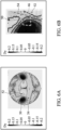
- FIG. 5A shows a chromatic aberration (Dx) diagram, with dual privacy panels, in accordance with one embodiment of the present disclosure (for example, Example 3).
- FIG. 5B shows a partial enlarged view of a specific viewing-angle area in FIG. 5A.
- FIG. 5A shows the chromatic aberration (Dx) diagram (e.g. a chromatic aberration (Dx) CONO diagram) under, for example, the conditions simulating the above-mentioned Example 3 and the conditions that the thicknesses of the two liquid-crystal layers in the dual privacy panels are different.
- FIG. 5A shows a negative-deviation area 50 (i.e. the area where Dx is negative), a positive-deviation area 52 (i.e. the area where Dx is positive), and a non-chromatic-aberration area 54 (i.e. the area where Dx is zero).
- Table 3 Dx (x_specification points-x (0, 0)) -0.007 Dx (min) -0.100 Dx (max) 0.104 ⁇ x 8.528
- Dx (x_specification points-x (0, 0)) is -0.007
- Dx (min) is -0.100
- Dx (max) is 0.104
- the sum of chromatic aberration ( ⁇ x) is 8.528.
- the average chromatic aberration in the driver's specific viewing-angle area 46 is 0.054.
- FIG. 6A shows a chromatic aberration (Dy) diagram, with dual privacy panels, in accordance with one embodiment of the present disclosure (for example, Example 3).
- FIG. 6B shows a partial enlarged view of a specific viewing-angle area in FIG. 6A .
- FIG. 6A shows the chromatic aberration (Dy) diagram (e.g. a chromatic aberration (Dy) CONO diagram) under, for example, the conditions simulating the above-mentioned Example 3 and the conditions that the thicknesses of the two liquid-crystal layers in the dual privacy panels are different.
- FIG. 6A shows a negative-deviation area 50 (i.e. the area where Dy is negative), a positive-deviation area 52 (i.e. the area where Dy is positive), and a non-chromatic-aberration area 54 (i.e. the area where Dy is zero).
- Table 4 Dy (y_specification points-y (0, 0)) -0.085 Dy (min) -0.192 Dy (max) 0.012 ⁇ y 16.696
- Example 3 Compared with Comparative Example 1, in Example 3, the minimum value of chromatic aberration (Dx (min) or Dy (min)), the maximum value of chromatic aberration (Dx (max) or Dy (max)), the sum of chromatic aberration ( ⁇ x or ⁇ y) and/or the average chromatic aberration are all lower than the numerical values of Comparative Example 1. It is obvious that the present disclosure adopts the configuration of dual privacy panels with opposite alignment directions (i.e.
- a mirror alignment which can improve the problem of bluish chromatic aberration in the specific viewing-angle area 46 (such as a driver's specific viewing-angle area) in the privacy mode through the mutual compensation effect between the positive-deviation and negative-deviation areas of chromaticity, effectively reducing the chromatic aberration in the specific viewing-angle area, so that, during the process of switching between the share mode and the privacy mode, the driver will not feel the chromatic aberration of the screen, which will affect the driving concentration.
- the specific viewing-angle area 46 such as a driver's specific viewing-angle area
- FIG. 7 shows a brightness diagram, with dual privacy panels, in accordance with one embodiment of the present disclosure.
- FIG. 7 shows the brightness diagram (CONO diagram) in the privacy mode when the alignment directions of the dual privacy panels are reversed (i.e. a mirror alignment) and the thicknesses of the two liquid-crystal layers in the dual privacy panels are different.
- the brightness of the central point (0, 0) in the privacy mode is taken as 100%.
- a luminance equipotential line "a" is marked on the figure (for example, a luminance equipotential line with a brightness of 2%, and the area outside the area surrounded by the luminance equipotential line "a” represents the area with a brightness lower than 2%).
- a luminance equipotential line "b" is further marked on the figure (for example, a luminance equipotential line with a brightness of 90%, and the area surrounded by the luminance equipotential line “b” represents the area with a brightness higher than 90%).
- the area with a brightness lower than 2% accounts for a large proportion in the specific viewing-angle area 46 (for example, a driver's specific viewing-angle area), which can effectively improve the viewing taste in the privacy mode.
- FIG. 7 is a brightness diagram (CONO diagram) in the privacy mode obtained by simulating the condition that the two liquid-crystal layers in the dual privacy panels have different thicknesses.
- CONO diagram brightness diagram
- FIG. 8 shows a relationship diagram between ⁇ and brightness, with dual privacy panels, under a driver's viewing angle in accordance with one embodiment of the present disclosure (such as the embodiment of FIG. 7 ).
- FIG. 8 is, for example, a relationship diagram between ⁇ and brightness (L%) taken from the line segment L1 in FIG. 7 (such as the curve designed by the present disclosure in the figure).
- the line segment L1 is, for example, at about 14-15 degrees of ⁇ , but not limited thereto.
- the angle ⁇ is, for example, an angle with the normal direction of the dual privacy panels. Under other requirements, the angle ⁇ may be selected from 0 to 20 degrees. It can be seen from FIG.
- the disclosed design can reduce the brightness of the area with a large viewing angle, or improve the problem of light leakage or taste at a large viewing angle.
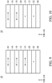
- FIG. 9 is the cross-sectional view of the electronic device 10.
- the embodiment of the electronic device 10 disclosed in FIG. 9 is similar to the embodiment of the electronic device 10 disclosed in FIG. 1 , and the similarities will not be repeated.
- the difference between the two is the configuration relationship of the first privacy panel 12, the second privacy panel 16 and the display panel 20.
- the second privacy panel 16 is disposed on the first privacy panel 12.
- the display panel 20 is disposed under the first privacy panel 12.
- the backlight 58 is disposed, for example, under the display panel 20 (such as a non-self-luminous panel).
- the polarizer 18 is disposed, for example, between the first privacy panel 12 and the second privacy panel 16.
- the polarizer 14 is disposed, for example, between the first privacy panel 12 and the display panel 20.
- the direction of the absorption axis of the polarizer 14 (such as X-axis direction, but not limited thereto) is parallel to the direction of the absorption axis of the polarizer 18 (such as X-axis direction, but not limited thereto).
- the configurations of the polarizer 14, the polarizer 18, the polarizer 42 and the polarizer 44 can be adjusted correspondingly.
- the directions of the absorption axis of the polarizer 14, the absorption axis of the polarizer 18, and the absorption axis of the polarizer 44 may be substantially parallel (for example, parallel to X-axis, but not limited thereto).
- the direction of the absorption axis of the polarizer 42 may be substantially perpendicular to that of the absorption axis of the polarizer 14 (for example, parallel to Y axis, but not limited thereto).
- FIG. 10 is the cross-sectional view of the electronic device 10.
- the embodiment of the electronic device 10 disclosed in FIG. 10 is similar to the embodiment of the electronic device 10 disclosed in FIG. 1 , and the similarities will not be repeated.
- the difference between the two is the configuration relationship of the first privacy panel 12, the second privacy panel 16 and the display panel 20.
- the second privacy panel 16 is disposed on the first privacy panel 12.
- the display panel 20 (such as a non-self-luminous panel) is disposed between the first privacy panel 12 and the second privacy panel 16.
- the backlight 58 is disposed under the first privacy panel 12.
- the configurations of the polarizer 14, the polarizer 18, the polarizer 42 and the polarizer 44 can be adjusted correspondingly.
- the direction of the absorption axis of the polarizer 14 is substantially parallel to the direction of the absorption axis of the polarizer 42 (for example, parallel to Y axis, but not limited thereto).
- the direction of the absorption axis of the polarizer 18 is substantially parallel to the direction of the absorption axis of the polarizer 44 (for example, parallel to X axis, but not limited thereto).
- the direction of the absorption axis of the polarizer 14 is substantially perpendicular to the direction of the absorption axis of the polarizer 18.
- the display panel 20 is, for example, a self-luminous panel, and the first privacy panel 12 and the second privacy panel 16 may be both disposed on the display panel 20.
- the first privacy panel 12 may be located between the display panel 20 and the second privacy panel 16.
- the display panel 20 and the first privacy panel 12 may share a polarizer as required.
Landscapes
- Physics & Mathematics (AREA)
- Nonlinear Science (AREA)
- General Physics & Mathematics (AREA)
- Chemical & Material Sciences (AREA)
- Crystallography & Structural Chemistry (AREA)
- Optics & Photonics (AREA)
- Mathematical Physics (AREA)
- Spectroscopy & Molecular Physics (AREA)
- Engineering & Computer Science (AREA)
- Theoretical Computer Science (AREA)
- Liquid Crystal (AREA)
- Thin Film Transistor (AREA)
- Devices For Indicating Variable Information By Combining Individual Elements (AREA)
Abstract
Description
- This application claims priority of
China Patent Application No. 202210458176.6, filed on April 27, 2022 - The present disclosure relates to an electronic device, and in particular it relates to an electronic device with dual privacy panels.
- Electronic products are widely used in different types of products. Different products have different requirements for privacy. For example, car monitors. Based on driving safety considerations, the monitor that can be viewed from the passenger's seat must have a privacy function, so as to reduce interference with the driver's concentration when playing video or displaying pictures or text.
- However, in the privacy modes employed by current privacy technology, the driver's viewing angle (for example, 30-50 degrees side viewing angle) will have a bluish chromatic aberration or light leakage at large viewing angles.
- Therefore, how to improve the above problems is a topic at present that needs to be discussed by the industry.
- It is an object of the present disclosure to provide an electronic device configured to overcome the afore-mentioned drawings, in particular configured for providing a privacy mode function of high viewing quality with a cost-efficient and simple set-up.
- This problem is solved by an electronic device as claimed in
claim 1. Further advantageous embodiments are the subject-matter of the dependent claims. - In accordance with one embodiment of the present disclosure, an electronic device is provided. The electronic device includes a first privacy panel and a second privacy panel disposed on the first privacy panel. The first privacy panel has a first alignment layer and a second alignment layer opposite each other. The second privacy panel has a third alignment layer and a fourth alignment layer opposite each other. The second alignment layer and the third alignment layer are located between the first alignment layer and the fourth alignment layer. The alignment axes of the first alignment layer, the second alignment layer, the third alignment layer and the fourth alignment layer are parallel. The angle between the alignment direction of the first alignment layer and the alignment direction of the third alignment layer is in a range from 160 to 200 degrees. The angle between the alignment direction of the second alignment layer and the alignment direction of the fourth alignment layer is in a range from 160 to 200 degrees.
- A detailed description is given in the following embodiments with reference to the accompanying drawings.
- The disclosure can be more fully understood from the following detailed description when read with the accompanying figures. It is worth noting that in accordance with standard practice in the industry, various features are not drawn to scale. In fact, the dimensions of the various features may be arbitrarily increased or reduced for clarity of discussion.
-
FIG. 1A shows a cross-sectional view of an electronic device in accordance with one embodiment of the present disclosure; -
FIG. 1B shows an enlarged cross-sectional view of two privacy panels of an electronic device in accordance with one embodiment of the present disclosure; -
FIG. 1C shows an enlarged cross-sectional view of two privacy panels of an electronic device in accordance with one embodiment of the present disclosure; -
FIG. 2 shows a specific viewing-angle area in accordance with one embodiment of the present disclosure; -
FIGs. 3-1(a)-(c) show diagrams of a lowest brightness area varying with thickness of a liquid-crystal layer under a specific viewing-angle area with a single privacy panel in accordance with one embodiment of the present disclosure; -
FIGs. 3-2(a)-(c) show diagrams of a chromaticity (Dx) varying with thickness of a liquid-crystal layer under a specific viewing-angle area with a single privacy panel in accordance with one embodiment of the present disclosure; -
FIGs. 3-3(a)-(c) show diagrams of a chromaticity (Dy) varying with thickness of a liquid-crystal layer under a specific viewing-angle area with a single privacy panel in accordance with one embodiment of the present disclosure; -
FIGs. 4-1(a)-(c) show diagrams of a lowest brightness area varying with thickness of a liquid-crystal layer under a specific viewing-angle area with a single privacy panel in accordance with another embodiment of the present disclosure; -
FIGs. 4-2(a)-(c) show diagrams of a chromaticity (Dx) varying with thickness of a liquid-crystal layer under a specific viewing-angle area with a single privacy panel in accordance with another embodiment of the present disclosure; -
FIGs. 4-3(a)-(c) show diagrams of a chromaticity (Dy) varying with thickness of a liquid-crystal layer under a specific viewing-angle area with a single privacy panel in accordance with another embodiment of the present disclosure; -
FIG. 5A shows a diagram of a chromatic aberration (Dx) with dual privacy panels in accordance with one embodiment of the present disclosure; -
FIG. 5B shows a partial enlarged view of a specific viewing-angle area inFIG. 5A ; -
FIG. 6A shows a diagram of a chromatic aberration (Dy) with dual privacy panels in accordance with one embodiment of the present disclosure; -
FIG. 6B shows a partial enlarged view of the specific viewing-angle area inFIG. 6A ; -
FIG. 7 shows a brightness diagram with dual privacy panels in accordance with one embodiment of the present disclosure; -
FIG. 8 shows a relationship between θ and brightness with dual privacy panels under a driver's viewing angle in accordance with one embodiment of the present disclosure; -
FIG. 9 shows a cross-sectional view of an electronic device in accordance with one embodiment of the present disclosure; and -
FIG. 10 shows a cross-sectional view of an electronic device in accordance with one embodiment of the present disclosure. - Various embodiments or examples are provided in the following description to implement different features of the present disclosure. The elements and arrangement described in the following specific examples are merely provided for introducing the present disclosure and serve as examples without limiting the scope of the present disclosure. For example, when a first component is referred to as "on a second component", it may directly contact the second component, or there may be other components in between, and the first component and the second component do not come in direct contact with one another.
- It should be understood that additional operations may be provided before, during, and/or after the described method. In accordance with some embodiments, some of the stages (or steps) described below may be replaced or omitted.
- In this specification, spatial terms may be used, such as "below", "lower", "above", "higher" and similar terms, for briefly describing the relationship between an element relative to another element in the figures. Besides the directions illustrated in the figures, the devices may be used or operated in different directions. When the device is turned to different directions (such as rotated 45 degrees or other directions), the spatially related adjectives used in it will also be interpreted according to the turned position. In some embodiments of the present disclosure, terms concerning attachments, coupling and the like, such as "connected" and "interconnected," refer to a relationship wherein structures are secured or attached to one another either directly or indirectly through intervening structures, as well as both movable or rigid attachments or relationships, unless expressly described otherwise.
- Herein, the terms "about", "around" and "substantially" typically mean a value is in a range of +/- 15% of a stated value, typically a range of +/- 10% of the stated value, typically a range of +/- 5% of the stated value, typically a range of +/- 3% of the stated value, typically a range of +/- 2% of the stated value, typically a range of +/- 1% of the stated value, or typically a range of +/- 0.5% of the stated value. It should be noted that, in the description, when it is mentioned that direction A is approximately parallel to direction B, it means that the included angle between direction A and direction B is between 0 degrees and 15 degrees (0 degrees ≤ included angle ≤ 15 degrees ). It should be noted that, in the description, when it is mentioned that direction A is approximately perpendicular to direction B, it means that the included angle between direction A and direction B is between 75 degrees and 90 degrees (75 degrees ≤ included angle ≤ 90 degrees ).
- It should be understood that, although the terms "first", "second", "third", etc. may be used herein to describe various elements, components, regions, layers, portions and/or sections, these elements, components, regions, layers, portions and/or sections should not be limited by these terms. These terms are only used to distinguish one element, component, region, layer, portion or section from another element, component, region, layer, portion or section. Thus, a first element, component, region, layer, portion or section discussed below could be termed a second element, component, region, layer, portion or section without departing from the teachings of the present disclosure.
- Unless defined otherwise, all technical and scientific terms used herein have the same meaning as commonly understood by one of ordinary skill in the art to which this disclosure belongs. It should be appreciated that, in each case, the term, which is defined in a commonly used dictionary, should be interpreted as having a meaning that conforms to the relative skills of the present disclosure and the background or the context of the present disclosure, and should not be interpreted in an idealized or overly formal manner unless so defined.
- Referring to
FIG. 1A , in accordance with one embodiment of the present disclosure, anelectronic device 10 is provided.FIG. 1A is the cross-sectional view of theelectronic device 10. - As shown in
FIG. 1A , theelectronic device 10 includes afirst privacy panel 12, apolarizer 14, asecond privacy panel 16, apolarizer 18, and adisplay panel 20. Thesecond privacy panel 16 is disposed on (above) thefirst privacy panel 12. Thepolarizer 14 is disposed between thefirst privacy panel 12 and thesecond privacy panel 16. Thedisplay panel 20 is disposed on thesecond privacy panel 16. Thepolarizer 18 is disposed between thesecond privacy panel 16 and thedisplay panel 20. -
FIG. 1B is an enlarged cross-sectional view of two privacy panels of an electronic device in accordance with one embodiment of the present disclosure. As shown inFIG. 1B , thefirst privacy panel 12 has afirst alignment layer 22 and asecond alignment layer 24 opposite each other. Thesecond privacy panel 16 has athird alignment layer 26 and afourth alignment layer 28 opposite each other. Thesecond alignment layer 24 and thethird alignment layer 26 are located between thefirst alignment layer 22 and thefourth alignment layer 28. The alignment axis 22' of thefirst alignment layer 22, the alignment axis 24' of thesecond alignment layer 24, the alignment axis 26' of thethird alignment layer 26, and the alignment axis 28' of thefourth alignment layer 28 are parallel with each other. Here "alignment axes being parallel (with each other)" means that, for example, taking the alignment axis 22' of thefirst alignment layer 22 as a reference, the angle difference between the alignment axis 22' of thefirst alignment layer 22 and the alignment axis 24' of thesecond alignment layer 24, the alignment axis 26' of thethird alignment layer 26, and the alignment axis 28' of thefourth alignment layer 28 is within about 20 degrees. InFIG. 1B , the alignment axis 22' of thefirst alignment layer 22, the alignment axis 24' of thesecond alignment layer 24, the alignment axis 26' of thethird alignment layer 26, and the alignment axis 28' of thefourth alignment layer 28 may be substantially parallel to Y axis, but not limited thereto. In addition, the angle between thealignment direction 22" (as indicated by the arrow in the figure) of thefirst alignment layer 22 and thealignment direction 26" (as indicated by the arrow in the figure) of thethird alignment layer 26 is in a range from about 160 to about 200 degrees. The angle between thealignment direction 24" (as indicated by the arrow in the figure) of thesecond alignment layer 24 and thealignment direction 28" (as indicated by the arrow in the figure) of thefourth alignment layer 28 is in a range from about 160 to about 200 degrees. The above-mentioned alignment direction is, for example, a tilting direction of liquid-crystal molecules adjacent to the alignment layer. The alignment direction may be substantially the alignment direction of the plush cloth. In thefirst privacy panel 12, the angle between thealignment direction 22" (as indicated by the arrow in the figure) of thefirst alignment layer 22 and thealignment direction 24" (as indicated by the arrow in the figure) of thesecond alignment layer 24 is in a range from about 160 to about 200 degrees. In thesecond privacy panel 16, the angle between thealignment direction 26" (as indicated by the arrow in the figure) of thethird alignment layer 26 and thealignment direction 28" (as indicated by the arrow in the figure) of thefourth alignment layer 28 is in a range from about 160 to about 200 degrees. - The
first privacy panel 12 further includes a first liquid-crystal layer 30 disposed between thefirst alignment layer 22 and thesecond alignment layer 24. Thesecond privacy panel 16 further includes a second liquid-crystal layer 32 disposed between thethird alignment layer 26 and thefourth alignment layer 28. In some embodiments, the thickness T1 of the first liquid-crystal layer 30 may be different from the thickness T2 of the second liquid-crystal layer 32. The thickness T1 of the first liquid-crystal layer 30 may be obtained by, for example, measuring the distance between thefirst alignment layer 22 and thesecond alignment layer 24 in the third direction D3. The thickness T2 of the second liquid-crystal layer 32 may be obtained by, for example, measuring the distance between thethird alignment layer 26 and thefourth alignment layer 28 in the third direction D3. In other embodiments, when thefirst privacy panel 12 or thesecond privacy panel 16 includes a plastic frame (not shown) surrounding the first liquid-crystal layer 30 or the second liquid-crystal layer 32, the thickness T1 of the first liquid-crystal layer 30 is obtained by, for example, measuring the thickness of the plastic frame of thefirst privacy panel 12 in the third direction D3. The thickness T2 of the second liquid-crystal layer 32 is obtained by, for example, measuring the thickness of the plastic frame of thesecond privacy panel 16 in the third direction D3. - In some embodiments, the thickness T1 of the first liquid-
crystal layer 30 may be the same as the thickness T2 of the second liquid-crystal layer 32. The aforementioned difference between the thickness T1 and the thickness T2 means that the difference between the two is at least greater than or equal to 0.2 µm. In some embodiments, the difference between the thickness T1 of the first liquid-crystal layer 30 and the thickness T2 of the second liquid-crystal layer 32 may be, for example, 0.3 µm to 2 µm, but is not limited thereto. In some embodiments, the difference between the thickness T1 of the first liquid-crystal layer 30 and the thickness T2 of the second liquid-crystal layer 32 may be, for example, 0.5 µm to 2 µm, but is not limited thereto. Thefirst privacy panel 12 includes alower substrate 34, anupper substrate 36, and the first liquid-crystal layer 30 located between thelower substrate 34 and theupper substrate 36. Thefirst alignment layer 22 may be disposed between thelower substrate 34 and the first liquid-crystal layer 30. Thesecond alignment layer 24 may be disposed between theupper substrate 36 and the first liquid-crystal layer 30. Thesecond privacy panel 16 includes alower substrate 38, anupper substrate 40, and the second liquid-crystal layer 32 located between thelower substrate 38 and theupper substrate 40. Thethird alignment layer 26 may be disposed between thelower substrate 38 and the second liquid-crystal layer 32. Thefourth alignment layer 28 may be disposed between theupper substrate 40 and the second liquid-crystal layer 32. In some embodiments, the lower substrates (34 and 38) and/or the upper substrates (36 and 40) include rigid or flexible substrates. The rigid substrate includes, for example, glass, ceramics, other suitable materials, or a combination thereof, but is not limited thereto. The flexible substrate includes, for example, a polyimide (PI) substrate, other suitable materials, or combinations thereof, but the present disclosure is not limited thereto. - The above-mentioned difference between the thickness T1 of the first liquid-
crystal layer 30 and the thickness T2 of the second liquid-crystal layer 32 is merely in some exemplary embodiments (e.g., Δn is about 0.2). The difference between the thickness T1 and the thickness T2 may be related to the refractive index difference (Δn=ne-no) of the materials of the first liquid-crystal layer 30 or the second liquid-crystal layer 32. In some embodiments, the difference between the product of the thickness T1 and the refractive index difference (Δn) of the first liquid-crystal layer 30 and the product of the thickness T2 and the refractive index difference (Δn) of the second liquid-crystal layer 32 may be between 60 nm and 400 nm, but is not limited thereto. - The
first privacy panel 12 and thesecond privacy panel 16 may be, for example, electronically controlled birefringence (ECB) mode privacy panels, but are not limited thereto. InFIG. 1B , the alignment direction of the lower alignment layer (i.e. the first alignment layer 22) and the upper alignment layer (i.e. the second alignment layer 24) of thefirst privacy panel 12 and the alignment direction of the lower alignment layer (i.e. the third alignment layer 26) and the upper alignment layer (i.e. the fourth alignment layer 28) of thesecond privacy panel 16 may be approximately opposite each other (i.e. mirror image design). For example, the angle between thealignment direction 22" of thefirst alignment layer 22 and thealignment direction 26" of thethird alignment layer 26 may be in a range from about 160 degrees to about 200 degrees. The angle between thealignment direction 24" of thesecond alignment layer 24 and thealignment direction 28" of thefourth alignment layer 28 may be in a range from about 160 degrees to about 200 degrees. - In addition, referring to
FIG. 1A andFIG.1B , the direction of the absorption axis 14' of the polarizer 14 (for example, towards Y-axis direction) may be substantially parallel to the alignment axis 22' of thefirst alignment layer 22. That is, the alignment axis 22' of thefirst alignment layer 22 is, for example, towards Y-axis direction. The direction of the absorption axis 18' of thepolarizer 18 may be substantially parallel to the direction of the absorption axis 14' of thepolarizer 14. The direction of the absorption axis 18' of thepolarizer 18 is, for example, towards Y-axis direction. - In
FIG. 1A , theelectronic device 10 further includes apolarizer 42 and/or apolarizer 44. Thepolarizer 42 may be disposed under thefirst privacy panel 12, that is, thepolarizer 14 and thepolarizer 42 are located on opposite sides of theprivacy panel 12, for example. Thepolarizer 44 may be disposed on thedisplay panel 20, that is, thepolarizer 18 and thepolarizer 44 are located on opposite sides of thedisplay panel 20, for example. The direction of the absorption axis 42' of thepolarizer 42 may be substantially parallel to the direction of the absorption axis 14' of thepolarizer 14. It should be noted that the directions of the absorption axes of the polarizers located on both sides of the display panel 20 (such as a non-self-luminous panel) are, for example, substantially perpendicular to each other. For example, thepolarizer 44 and thepolarizer 18 may be located on both sides of thedisplay panel 20. The direction of the absorption axis 44' of thepolarizer 44 may be substantially perpendicular to the direction of the absorption axis 18' of thepolarizer 18. In some embodiments, the absorption axes of the polarizers disposed on both sides of thefirst privacy panel 12 may be substantially in the same direction (i.e. parallel). For example, the direction of the absorption axis 14' of thepolarizer 14 may be substantially parallel to the direction of the absorption axis 42' of thepolarizer 42. For example, the direction of the absorption axis 14' and the direction of the absorption axis 42' are substantially parallel to Y-axis, but not limited thereto. The absorption axes of the polarizers disposed on both sides of thesecond privacy panel 16 may be substantially in the same direction (i.e. parallel). For example, the direction of the absorption axis 14' of thepolarizer 14 may be substantially parallel to the direction of the absorption axis 18' of thepolarizer 18. For example, the direction of the absorption axis 14' and the direction of the absorption axis 18' are substantially parallel to Y-axis, but not limited thereto. In some embodiments, thefirst privacy panel 12, thesecond privacy panel 16 and/or thedisplay panel 20 may selectively share the polarizer. For example, thefirst privacy panel 12 and thesecond privacy panel 16 may share thepolarizer 14. Thesecond privacy panel 16 and thedisplay panel 20 may share thepolarizer 18, but is not limited thereto. In other embodiments (not shown), thefirst privacy panel 12, thesecond privacy panel 16 or thedisplay panel 20 may optionally not share the polarizer. For example, another polarizer (not shown) may be added between thefirst privacy panel 12 and thesecond privacy panel 16. Moreover, the direction of the absorption axis of the other polarizer and the direction of the absorption axis 14' of thepolarizer 14 may be substantially in the same direction (i.e. parallel), or, for example, another polarizer (not shown) may be added between thesecond privacy panel 16 and thedisplay panel 20. Moreover, the direction of the absorption axis of the other polarizer and the direction of the absorption axis 18' of thepolarizer 18 may be substantially in the same direction (i.e. parallel). -
FIG. 1C is an enlarged cross-sectional view of two privacy panels of an electronic device in accordance with one embodiment of the present disclosure. The difference betweenFIG. 1B and FIG. 1C is that thealignment direction 22" of thefirst alignment layer 22 in thefirst privacy panel 12 inFIG. 1C is approximately 180 degrees different from thealignment direction 22" of thefirst alignment layer 22 in thefirst privacy panel 12 inFIG. 1B . Similarly, thealignment direction 24" of thesecond alignment layer 24 in thefirst privacy panel 12 inFIG. 1C is approximately 180 degrees different from thealignment direction 24" of thesecond alignment layer 24 in thefirst privacy panel 12 inFIG. 1B . Similarly, thealignment direction 26" of thethird alignment layer 26 in thesecond privacy panel 16 inFIG. 1C is approximately 180 degrees different from thealignment direction 26" of thethird alignment layer 26 in thesecond privacy panel 16 inFIG. 1B . Similarly, thealignment direction 28" of thefourth alignment layer 28 in thesecond privacy panel 16 inFIG. 1C is approximately 180 degrees different from thealignment direction 28" of thefourth alignment layer 28 in thesecond privacy panel 16 inFIG. 1B . - It should be noted that when the electronic device of the present disclosure is applied to a car monitor, the direction from the position of the driver (left-hand drive) to the position of the co-driver (on the right side of the driver) is, for example, the arrow direction of X-axis in
FIG. 1A . - The evaluation index of the privacy effect of the present disclosure will be described below.
- (1) Privacy Ratio (PR): It is measured in privacy mode and expressed by the following equation (I).

- In equation (I), the parameter θ may represent a tilt angle, which represents an angle with a normal direction (for example, Z-axis direction) of the electronic device. The angle θ (tilt angle) is, for example, between 0 degrees and ± 90 degrees. θ=0 degrees refers to the direction parallel to the normal direction (for example, Z-axis direction) of the electronic device. As the angle θ (tilt angle) becomes more positive or negative, the angle with the normal direction (for example, Z-axis direction) of the electronic device becomes larger. The parameter ϕ (azimuth angle) may represent an angle on the plane of the X-Y axis. The angle ϕ (azimuth angle) is, for example, between 0 degrees and 360 degrees. L (0, 0) in equation (I) represents the brightness at the central point from top view. That is, θ=0 and ϕ=0 represent at the central point from top view. In addition, there may be different specification points in accordance with the application of the electronic device. L (θ, ϕ) represents the brightness at the specification points (θ, ϕ) of the corresponding product. The smaller the aforementioned privacy ratio (PR) is (that is, the smaller the brightness at the specification points in the privacy mode is), the better the privacy effect is.
- (2) ON/OFF ratio: It is expressed by the following equation (II).

- In equation (II), the parameters θ and ϕ are defined as above. L (θ, ϕ)s represents the brightness at the specification points corresponding to different θ and ϕ in the share mode. L (θ, ϕ)p represents the brightness at the specification points corresponding to different θ and ϕ in the privacy mode. The smaller the aforementioned ON/OFF ratio is (that is, the smaller the brightness at the specification point in the privacy mode is), the better the privacy effect is. If the ON/OFF ratio is 1 (maximum value), it means that L (θ, ϕ)s=L (θ, ϕ)p, which means that there is no privacy effect. In other words, the smaller the ON/OFF ratio is, the larger the brightness variation ratio at the specification points with the privacy panel in the on/off mode is, and the better the privacy effect is.
- (3) Chromatic Aberration (Dy): It is measured in privacy mode and expressed by the following equation (III).

- In equation (III), the parameters θ and ϕ are defined as above. y (θ, ϕ) represents the chromaticity at the specification points corresponding to different θ and ϕ. y (0, 0) represents the chromaticity at the central point from top view. The closer the chromatic aberration (Dy) is to zero (that is, the smaller the difference between the chromaticity at the specification points in the privacy mode and the chromaticity at the central point is), the better the privacy effect is, and the smaller the color shift is.
- (4) Chromatic Aberration (Dx): It is measured in privacy mode and expressed by the following equation (IV).

- In equation (IV), the parameters θ and ϕ are defined as above. x (θ, ϕ) represents the chromaticity at the specification points corresponding to different θ and ϕ. x (0, 0) represents the chromaticity at the central point from top view. The closer the chromatic aberration (Dx) is to zero (that is, the smaller the difference between the chromaticity at the specification points in the privacy mode and the chromaticity at the central point is), the better the privacy effect is, and the smaller the color shift is.
- (5) Sum of Chromatic Aberration (ΣΔy): It is expressed by the following equation (V).

- In equation (V), the parameter yp represents the chromaticity at each point in the privacy mode within the viewing range (for example, the driver's viewing range). The parameter ys represents the chromaticity at the specification points in the share mode. The sum of the chromatic aberration (ΣΔy) represents the sum of the chromatic aberration between the chromaticity yp and ys at each point. The smaller the sum of the chromatic aberration (ΣΔy) is (that is, the smaller the sum of the chromatic aberration between the chromaticity at each point in the privacy mode and the chromaticity at the specification points in the share mode within the viewing angle range is), the better the privacy effect is, and the smaller the color shift is.
- (6) Sum of Chromatic Aberration (ΣΔx): It is expressed by the following equation (VI).

- In equation (VI), the parameter xp represents the chromaticity at each point in the privacy mode within the viewing range (for example, the driver's viewing range). The parameter xs represents the chromaticity at the specification points in the share mode. The sum of the chromatic aberration (ΣΔx) represents the sum of the chromatic aberration between the chromaticity xp and xs at each point. The smaller the sum of the chromatic aberration (ΣΔx) is (that is, the smaller the sum of the chromatic aberration between the chromaticity at each point in the privacy mode and the chromaticity at the specification points in the share mode within the viewing angle range is), the better the privacy effect is, and the smaller the color shift is.
- With regard to the privacy panel of the electronically controlled birefringence (ECB) mode, the position of the viewing angle (area) with the darkest brightness in the electronic device may be adjusted by controlling the voltage or the thickness of the liquid-crystal layer.
-
FIG. 2 shows a specific viewing-angle area in accordance with one embodiment of the present disclosure. - Referring to
FIG. 2 , the specific viewing-angle area 46 is disclosed (for example, the area bounded by the ranges extending approximately 7 degrees to 10 degrees in horizontal and vertical directions from the specification point respectively). The above-mentioned specific viewing-angle area 46 is, for example, a driver's specific viewing-angle area. The following uses Examples 1 and 2 to illustrate the variations in the brightness and chromatic aberration within the above-mentioned area when the liquid-crystal layer of a single privacy panel has different thicknesses. - Single privacy panel (the
first privacy panel 12 shown inFIG. 1C ) - FIG. 3-1 shows diagrams (for example, simulation diagrams) of a lowest brightness area varying with thickness of a liquid-crystal layer under a specific viewing-angle area, with a single privacy panel, in accordance with one embodiment of the present disclosure (Example 1). FIG. 3-1 is obtained, for example, according to the above-mentioned equation (II) of the evaluation index, that is, "ON/OFF ratio". The area with the minimum ON/OFF ratio may represent the lowest brightness area. The lowest brightness area is, for example, equivalent to the area with the largest brightness variation ratio with the privacy panel in the on/off mode. The smaller the brightness variation ratio is, the better the privacy effect is.
- FIG. 3-2 shows diagrams (for example, simulation diagrams) of a chromaticity (Dx) varying with thickness of a liquid-crystal layer under a specific viewing-angle area, with a single privacy panel, in accordance with one embodiment of the present disclosure (Example 1). The chromaticity (Dx) in FIG. 3-2 is obtained, for example, according to the above-mentioned equation (IV) of the evaluation index.
- FIG. 3-3 shows diagrams (for example, simulation diagrams) of a chromaticity (Dy) varying with thickness of a liquid-crystal layer under a specific viewing-angle area, with a single privacy panel, in accordance with one embodiment of the present disclosure (Example 1). The chromaticity (Dy) in FIG. 3-3 is obtained, for example, according to the above-mentioned equation (III) of the evaluation index.
- Referring to FIG. 3-1, it can be seen from FIG. 3-1 that when the thickness of the liquid-crystal layer is small, the lowest brightness area 48 (that is, the area with the minimum value of ON/OFF ratio) is, for example, roughly located in the left half of the specific viewing-angle area 46 (i.e. a driver's viewing-angle area), as shown in
FIG. 3-1(a) . As the thickness of the liquid-crystal layer varies from small to large, thelowest brightness area 48, for example, gradually moves towards the direction in which θ becomes smaller, as shown inFIG. 3-1(b) , and finally to the right half of the driver's specific viewing-angle area 46, as shown inFIG. 3-1(c) . - Referring to FIG. 3-2, FIG. 3-2 includes a negative-deviation area 50 (that is, Dx in the evaluation index in this area is a negative value), a positive-deviation area 52 (that is, Dx in the evaluation index in this area is a positive value), and a non-chromatic-aberration area 54 (that is, Dx in the evaluation index in this area is zero). The negative-
deviation area 50 is an area formed by the points with negative values after subtracting the chromaticity x at the central point from the chromaticity x at each point in the privacy mode. The positive-deviation area 52 is an area formed by the points with positive values after subtracting the chromaticity x at the central point from the chromaticity x at each point in the privacy mode. The non-chromatic-aberration area 54 is an area formed by the points close to zero after subtracting the chromaticity x at the central point from the chromaticity x at each point in the privacy mode. Compared with the non-chromatic-aberration area 54, the negative-deviation area 50 is, for example, an area with relatively bluish chroma, but is not limited thereto. Compared with the non-chromatic-aberration area 54, the positive-deviation area 52 is, for example, an area with relatively yellowish chroma, but is not limited thereto. It can be seen from FIG. 3-2 that when the thickness of the liquid-crystal layer is small, the proportion of the negative-deviation area 50 in the specific viewing-angle area 46 (i.e. a driver's specific viewing-angle area) is larger than that of the positive-deviation area 52, as shown inFIG. 3-2(a) . As the thickness of the liquid-crystal layer varies from small to large, the proportion of the negative-deviation area 50 in the specific viewing-angle area 46 is more enlarged, as shown inFIG. 3-2(b) , and finally to almost occupy the specific viewing-angle area 46, as shown inFIG. 3-2(c) . - Referring to FIG. 3-3, similar to FIG. 3-2, FIG. 3-3 includes a negative-deviation area 50 (that is, Dy in the evaluation index in this area is a negative value), a positive-deviation area 52 (that is, Dy in the evaluation index in this area is a positive value), and a non-chromatic-aberration area 54 (that is, Dy in the evaluation index in this area is zero). The negative-
deviation area 50 is an area formed by the points with negative values after subtracting the chromaticity y at the central point from the chromaticity y at each point in the privacy mode. The positive-deviation area 52 is an area formed by the points with positive values after subtracting the chromaticity y at the central point from the chromaticity y at each point in the privacy mode. The non-chromatic-aberration area 54 is an area formed by the points close to zero after subtracting the chromaticity y at the central point from the chromaticity y at each point in the privacy mode. Compared with the non-chromatic-aberration area 54, the negative-deviation area 50 is, for example, an area with relatively bluish chroma, but is not limited thereto. Compared with the non-chromatic-aberration area 54, the positive-deviation area 52 is, for example, an area with relatively yellowish chroma, but is not limited thereto. It can be seen from FIG. 3-3 that when the thickness of the liquid-crystal layer is small, the proportion of the negative-deviation area 50 in the specific viewing-angle area 46 (i.e. a driver's specific viewing-angle area) is larger than that of the positive-deviation area 52, as shown inFIG. 3-3(a) . As the thickness of the liquid-crystal layer varies from small to large, the proportion of the negative-deviation area 50 in the specific viewing-angle area 46 is more enlarged, as shown inFIG. 3-3(b) , and finally to almost occupy the specific viewing-angle area 46, as shown inFIG. 3-3(c) . - It should be noted that the result diagrams in FIGs. 3-1 to 3-3 are merely used as an example of one of the embodiments. The
lowest brightness area 48 shown in FIG. 3-1, or the non-chromatic-aberration area 54 (Dx=0), the negative-deviation area 50 (Dx<0) or the positive-deviation area 52 (Dx>0) as shown in FIG. 3-2, or the non-chromatic-aberration area 54 (Dy=0), the negative-deviation area 50 (Dy<0) or the positive-deviation area 52 (Dy>0) as shown in FIG. 3-3, may be slightly different according to the material selection of each layer (such as liquid-crystal layer or substrate, but not limited thereto) in the privacy panel to be measured or the thickness of the liquid-crystal layer. - Single privacy panel (the
second privacy panel 16 shown inFIG. 1C ) - FIG. 4-1 shows diagrams (for example, simulation diagrams) of a lowest brightness area varying with thickness of a liquid-crystal layer under a specific viewing-angle area, with a single privacy panel, in accordance with another embodiment of the present disclosure (Example 2). FIG. 4-1 is obtained, for example, according to the above-mentioned equation (II) of the evaluation index, that is, "ON/OFF ratio". The area with the minimum ON/OFF ratio may represent the lowest brightness area. The lowest brightness area is, for example, equivalent to the area with the largest brightness variation ratio with the privacy panel in the on/off mode. The smaller the brightness variation ratio is, the better the privacy effect is.
- FIG. 4-2 shows diagrams (for example, simulation diagrams) of a chromaticity (Dx) varying with thickness of a liquid-crystal layer under a specific viewing-angle area, with a single privacy panel (for example, the
second privacy panel 16 shown inFIG. 1C ), in accordance with another embodiment of the present disclosure (Example 2). The chromaticity (Dx) in FIG. 4-2 is obtained, for example, according to the above-mentioned equation (IV) of the evaluation index. - FIG. 4-3 shows diagrams (for example, simulation diagrams) of a chromaticity (Dy) varying with thickness of a liquid-crystal layer under a specific viewing-angle area, with a single privacy panel, in accordance with another embodiment of the present disclosure (Example 2). The chromaticity (Dy) in FIG. 4-3 is obtained, for example, according to the above-mentioned equation (III) of the evaluation index. Referring to FIG. 4-1, it can be seen from FIG. 4-1 that when the thickness of the liquid-crystal layer is small, the lowest brightness area 48 (roughly the area with the minimum value of ON/OFF ratio) is, for example, adjacent to the left half of the specific viewing-angle area 46 (i.e. a driver's viewing-angle area), but not located in the specific viewing-
angle area 46, as shown inFIG. 4-1(a) . As the thickness of the liquid-crystal layer varies from small to large, thelowest brightness area 48 gradually moves towards the direction in which θ becomes smaller, as shown inFIG. 4-1(b) , and finally to the left half of the specific viewing-angle area 46, as shown inFIG. 4-1(c) . - Referring to FIG. 4-2, FIG. 4-2 includes a negative-deviation area 50 (that is, Dx in the evaluation index in this area is a negative value), a positive-deviation area 52 (that is, Dx in the evaluation index in this area is a positive value), and a non-chromatic-aberration area 54 (that is, Dx in the evaluation index in this area is zero). The definition of the negative-
deviation area 50, the positive-deviation area 52 and the non-chromatic-aberration area 54 may refer to FIG. 3-2 above. It can be seen from FIG. 4-2 that when the thickness of the liquid-crystal layer is small, the proportion of the positive-deviation area 52 in the specific viewing-angle area 46 (for example, a driver's specific viewing-angle area) is larger than that of the negative-deviation area 50, as shown inFIG. 4-2(a) . As the thickness of the liquid-crystal layer varies from small to large, the proportion of the negative-deviation area 50 in the specific viewing-angle area 46 (for example, a driver's specific viewing-angle area) is more enlarged, as shown inFIG. 4-2(b) , and finally to account for more than half of the driver's specific viewing-angle area 46, as shown inFIG. 4-2(c) . - Referring to FIG. 4-3, FIG. 4-3 includes a negative-deviation area 50 (that is, Dy in the evaluation index in this area is a negative value), a positive-deviation area 52 (that is, Dy in the evaluation index in this area is a positive value), and a non-chromatic-aberration area 54 (that is, Dy in the evaluation index in this area is zero). It can be seen from FIG. 4-3 that when the thickness of the liquid-crystal layer is small, the proportion of the positive-
deviation area 52 in the specific viewing-angle area 46 (for example, a driver's specific viewing-angle area) is larger than that of the negative-deviation area 50, as shown inFIG. 4-3(a) . As the thickness of the liquid-crystal layer varies from small to large, the proportion of the negative-deviation area 50 in the specific viewing-angle area 46 (for example, a driver's specific viewing-angle area) is more enlarged, as shown inFIG. 4-3(b) , and finally to account for more than half of the driver's specific viewing-angle area 46, as shown inFIG. 4-3(c) . - It should be noted that the result diagrams in FIGs. 4-1 to 4-3 are merely used as an example of one of the embodiments. The
lowest brightness area 48 shown in FIG. 4-1, or the non-chromatic-aberration area 54 (Dx=0), the negative-deviation area 50 (Dx<0) or the positive-deviation area 52 (Dx>0) as shown in FIG. 4-2, or the non-chromatic-aberration area 54 (Dy=0), the negative-deviation area 50 (Dy<0) or the positive-deviation area 52 (Dy>0) as shown in FIG. 4-3, may be slightly different according to the material selection of each layer (such as liquid-crystal layer or substrate, but not limited thereto) in the privacy panel to be measured, the thickness of the liquid-crystal layer or the brightness uniformity of the backlight used. - The result diagrams in FIGs. 3-1 to 3-3 or the result diagrams in FIGs. 4-1 to 4-3 are, for example, measured under a backlight with high brightness uniformity. For example, a light source whose luminance value varies within 20% or within 10% under different viewing angles, but not limited thereto.
- Dual privacy panels with the same alignment direction
- The same alignment direction of the above-mentioned dual privacy panels means that the alignment directions of the lower alignment layers of the two privacy panels are approximately the same, and the alignment directions of the upper alignment layers of the two privacy panels are approximately the same.
- Table 1 below shows Dx (x_specification points-x (0, 0)), Dx (min), Dx (max) and ΣΔx under the conditions simulating Comparative Example 1, and the calculation method may employ equation (IV) of Dx=x(θ,ϕ) - x(0,0) and equation (VI) of ΣΔx= Σ(xp-xs) in the above evaluation index.
- Table 2 below shows Dy (y_specification points-y (0, 0)), Dy (min), Dy (max) and ΣΔy under the conditions simulating Comparative Example 1, and the calculation method may employ equation (III) of Dy=y(θ,ϕ) - y(0,0) and equation (V) of ΣΔy= Σ(yp-ys) in the above evaluation index.
Table 1 Dx (x_specification points-x (0, 0)) -0.044 Dx (min) -0.119 Dx (max) 0.117 ∑Δx 13.055 Table 2 Dy (y_specification points-y (0, 0)) -0.138 Dy (min) -0.212 Dy (max) 0.030 ∑Δy 26.343 - According to the above simulation results (as shown in Table 1), Dx (x_specification points-x (0, 0)) is -0.044, Dx (min) is -0.119, Dx (max) is 0.117, and the sum of chromatic aberration (ΣΔx) is 13.055. In addition, according to the number of points measured, the average chromatic aberration in the driver's specific viewing-angle area is obtained as 0.082.
- According to the above simulation results (as shown in Table 2), Dy (y_specification points-y (0, 0)) is -0.138, Dy (min) is -0.212, Dy (max) is 0.030, and the sum of chromatic aberration (ΣΔy) is 26.343. In addition, according to the number of points measured, the average chromatic aberration in the driver's specific viewing-angle area is obtained as 0.116.
- Dual privacy panels with reverse alignment directions
- The reverse alignment directions of the above-mentioned dual privacy panels mean that the alignment directions of the lower alignment layers of the two privacy panels are roughly opposite, and the alignment directions of the upper alignment layers of the two privacy panels are roughly opposite, such as the situation illustrated in
FIGs. 1B and 1C . -
FIG. 5A shows a chromatic aberration (Dx) diagram, with dual privacy panels, in accordance with one embodiment of the present disclosure (for example, Example 3).FIG. 5B shows a partial enlarged view of a specific viewing-angle area inFIG. 5A. FIG. 5A shows the chromatic aberration (Dx) diagram (e.g. a chromatic aberration (Dx) CONO diagram) under, for example, the conditions simulating the above-mentioned Example 3 and the conditions that the thicknesses of the two liquid-crystal layers in the dual privacy panels are different.FIG. 5A shows a negative-deviation area 50 (i.e. the area where Dx is negative), a positive-deviation area 52 (i.e. the area where Dx is positive), and a non-chromatic-aberration area 54 (i.e. the area where Dx is zero). - In addition, Table 3 below shows Dx (x_specification points-x (0, 0)), Dx (min), Dx (max) and ΣΔx under the conditions simulating Example 3, and the calculation method may employ equation (IV) of Dx= x(θ,ϕ) - x(0,0) and equation (VI) of ΣΔx= Σ(xp-xs) in the above evaluation index.
Table 3 Dx (x_specification points-x (0, 0)) -0.007 Dx (min) -0.100 Dx (max) 0.104 ∑Δx 8.528 - It can be obtained from
FIGs. 5A and 5B (or Table 3 above) that Dx (x_specification points-x (0, 0)) is -0.007, Dx (min) is -0.100, Dx (max) is 0.104, and the sum of chromatic aberration (ΣΔx) is 8.528. Next, according to the number of points measured, the average chromatic aberration in the driver's specific viewing-angle area 46 is 0.054. -
FIG. 6A shows a chromatic aberration (Dy) diagram, with dual privacy panels, in accordance with one embodiment of the present disclosure (for example, Example 3).FIG. 6B shows a partial enlarged view of a specific viewing-angle area inFIG. 6A . -
FIG. 6A shows the chromatic aberration (Dy) diagram (e.g. a chromatic aberration (Dy) CONO diagram) under, for example, the conditions simulating the above-mentioned Example 3 and the conditions that the thicknesses of the two liquid-crystal layers in the dual privacy panels are different.FIG. 6A shows a negative-deviation area 50 (i.e. the area where Dy is negative), a positive-deviation area 52 (i.e. the area where Dy is positive), and a non-chromatic-aberration area 54 (i.e. the area where Dy is zero). - In addition, Table 4 below shows Dy (y_specification points-y (0, 0)), Dy (min), Dy (max) and ΣΔy under the conditions simulating Example 3, and the calculation method may employ equation (III) of Dy= y(θ,ϕ) - y(0,0) and equation (V) of ΣΔy= Σ(yp-ys) in the above evaluation index.
Table 4 Dy (y_specification points-y (0, 0)) -0.085 Dy (min) -0.192 Dy (max) 0.012 ∑Δy 16.696 - It can be obtained from
FIGs. 6A and 6B (or Table 4 above) that Dy (y_specification points-y (0, 0)) is -0.085, Dy (min) is -0.192, Dy (max) is 0.012, and the sum of chromatic aberration (ΣΔy) is 16.696. Next, according to the number of points measured, the average chromatic aberration in the driver's specific viewing-angle area 46 is 0.105. - Compared with Comparative Example 1, in Example 3, the minimum value of chromatic aberration (Dx (min) or Dy (min)), the maximum value of chromatic aberration (Dx (max) or Dy (max)), the sum of chromatic aberration (ΣΔx or ΣΔy) and/or the average chromatic aberration are all lower than the numerical values of Comparative Example 1. It is obvious that the present disclosure adopts the configuration of dual privacy panels with opposite alignment directions (i.e. a mirror alignment), which can improve the problem of bluish chromatic aberration in the specific viewing-angle area 46 (such as a driver's specific viewing-angle area) in the privacy mode through the mutual compensation effect between the positive-deviation and negative-deviation areas of chromaticity, effectively reducing the chromatic aberration in the specific viewing-angle area, so that, during the process of switching between the share mode and the privacy mode, the driver will not feel the chromatic aberration of the screen, which will affect the driving concentration.
-
FIG. 7 shows a brightness diagram, with dual privacy panels, in accordance with one embodiment of the present disclosure.FIG. 7 shows the brightness diagram (CONO diagram) in the privacy mode when the alignment directions of the dual privacy panels are reversed (i.e. a mirror alignment) and the thicknesses of the two liquid-crystal layers in the dual privacy panels are different. InFIG. 7 , for example, the brightness of the central point (0, 0) in the privacy mode is taken as 100%. A luminance equipotential line "a" is marked on the figure (for example, a luminance equipotential line with a brightness of 2%, and the area outside the area surrounded by the luminance equipotential line "a" represents the area with a brightness lower than 2%). A luminance equipotential line "b" is further marked on the figure (for example, a luminance equipotential line with a brightness of 90%, and the area surrounded by the luminance equipotential line "b" represents the area with a brightness higher than 90%). It can be seen fromFIG. 7 , in the present disclosure, by matching the dual privacy panels with opposite alignment directions (i.e. a mirror alignment) and/or with different thicknesses of the liquid-crystal layers, the area with a brightness lower than 2% accounts for a large proportion in the specific viewing-angle area 46 (for example, a driver's specific viewing-angle area), which can effectively improve the viewing taste in the privacy mode. It should be noted thatFIG. 7 is a brightness diagram (CONO diagram) in the privacy mode obtained by simulating the condition that the two liquid-crystal layers in the dual privacy panels have different thicknesses. However, according to other simulations (not shown), under the conditions that the dual privacy panels have opposite alignment directions (i.e. a mirror alignment) and the two liquid-crystal layers in the dual privacy panels have the same thickness, the viewing taste in the privacy mode can still be improved. InFIG. 7 , for example, by further adjusting the thicknesses relationship between the two liquid-crystal layers, the viewing taste in the privacy mode can thus be further improved. -
FIG. 8 shows a relationship diagram between θ and brightness, with dual privacy panels, under a driver's viewing angle in accordance with one embodiment of the present disclosure (such as the embodiment ofFIG. 7 ).FIG. 8 is, for example, a relationship diagram between θ and brightness (L%) taken from the line segment L1 inFIG. 7 (such as the curve designed by the present disclosure in the figure). The line segment L1 is, for example, at about 14-15 degrees of β, but not limited thereto. The angle β is, for example, an angle with the normal direction of the dual privacy panels. Under other requirements, the angle β may be selected from 0 to 20 degrees. It can be seen fromFIG. 8 that, compared with the curve of the general design (the same alignment direction of the dual privacy panels), the brightness (L%) of the curve designed by the present disclosure (the reversed alignment directions of the dual privacy panels) decreases at a large viewing angle (i.e., θ is ± 50 degrees to ± 80 degrees), so the privacy effect of the large viewing angle is improved. That is, compared with the general design, the disclosed design can reduce the brightness of the area with a large viewing angle, or improve the problem of light leakage or taste at a large viewing angle. - Referring to
FIG. 9 , in accordance with one embodiment of the present disclosure, anelectronic device 10 is provided.FIG. 9 is the cross-sectional view of theelectronic device 10. - The embodiment of the
electronic device 10 disclosed inFIG. 9 is similar to the embodiment of theelectronic device 10 disclosed inFIG. 1 , and the similarities will not be repeated. The difference between the two is the configuration relationship of thefirst privacy panel 12, thesecond privacy panel 16 and thedisplay panel 20. InFIG. 9 , thesecond privacy panel 16 is disposed on thefirst privacy panel 12. Thedisplay panel 20 is disposed under thefirst privacy panel 12. Thebacklight 58 is disposed, for example, under the display panel 20 (such as a non-self-luminous panel). In this embodiment, thepolarizer 18 is disposed, for example, between thefirst privacy panel 12 and thesecond privacy panel 16. Thepolarizer 14 is disposed, for example, between thefirst privacy panel 12 and thedisplay panel 20. The direction of the absorption axis of the polarizer 14 (such as X-axis direction, but not limited thereto) is parallel to the direction of the absorption axis of the polarizer 18 (such as X-axis direction, but not limited thereto). In this embodiment, the configurations of thepolarizer 14, thepolarizer 18, thepolarizer 42 and thepolarizer 44 can be adjusted correspondingly. For example, the directions of the absorption axis of thepolarizer 14, the absorption axis of thepolarizer 18, and the absorption axis of thepolarizer 44 may be substantially parallel (for example, parallel to X-axis, but not limited thereto). The direction of the absorption axis of thepolarizer 42 may be substantially perpendicular to that of the absorption axis of the polarizer 14 (for example, parallel to Y axis, but not limited thereto). - Referring to
FIG. 10 , in accordance with one embodiment of the present disclosure, anelectronic device 10 is provided.FIG. 10 is the cross-sectional view of theelectronic device 10. - The embodiment of the
electronic device 10 disclosed inFIG. 10 is similar to the embodiment of theelectronic device 10 disclosed inFIG. 1 , and the similarities will not be repeated. The difference between the two is the configuration relationship of thefirst privacy panel 12, thesecond privacy panel 16 and thedisplay panel 20. InFIG. 10 , thesecond privacy panel 16 is disposed on thefirst privacy panel 12. The display panel 20 (such as a non-self-luminous panel) is disposed between thefirst privacy panel 12 and thesecond privacy panel 16. Thebacklight 58 is disposed under thefirst privacy panel 12. In this embodiment, the configurations of thepolarizer 14, thepolarizer 18, thepolarizer 42 and thepolarizer 44 can be adjusted correspondingly. The direction of the absorption axis of thepolarizer 14 is substantially parallel to the direction of the absorption axis of the polarizer 42 (for example, parallel to Y axis, but not limited thereto). The direction of the absorption axis of thepolarizer 18 is substantially parallel to the direction of the absorption axis of the polarizer 44 (for example, parallel to X axis, but not limited thereto). The direction of the absorption axis of thepolarizer 14 is substantially perpendicular to the direction of the absorption axis of thepolarizer 18. - In other embodiments (not shown), the
display panel 20 is, for example, a self-luminous panel, and thefirst privacy panel 12 and thesecond privacy panel 16 may be both disposed on thedisplay panel 20. Thefirst privacy panel 12 may be located between thedisplay panel 20 and thesecond privacy panel 16. Thedisplay panel 20 and thefirst privacy panel 12 may share a polarizer as required. - Although some embodiments of the present disclosure and their advantages have been described in detail, it should be understood that various changes, substitutions and alterations can be made herein without departing from the spirit and scope of the disclosure as defined by the appended claims. The features of the various embodiments can be used in any combination as long as they do not depart from the spirit and scope of the present disclosure. Moreover, the scope of the present application is not intended to be limited to the particular embodiments of the process, machine, manufacture, composition of matter, means, methods and steps described in the specification. As one of ordinary skill in the art will readily appreciate from the present disclosure, processes, machines, manufacture, compositions of matter, means, methods, or steps, presently existing or later to be developed, that perform substantially the same function or achieve substantially the same result as the corresponding embodiments described herein may be utilized according to the present disclosure. Accordingly, the appended claims are intended to include within their scope such processes, machines, manufacture, compositions of matter, means, methods or steps. In addition, each claim constitutes an individual embodiment, and the claimed scope of the present disclosure includes the combinations of the claims and embodiments. The scope of protection of present disclosure is subject to the definition of the scope of the appended claims. Any embodiment or claim of the present disclosure does not need to meet all the purposes, advantages, and features disclosed in the present disclosure.
Claims (15)
- An electronic device (10), comprising:a first privacy panel (12) having a first alignment layer (22) and a second alignment layer (24) opposite each other; anda second privacy panel (16) disposed on the first privacy panel (12), having a third alignment layer (26) and a fourth alignment layer (28) opposite each other;wherein the second alignment layer (24) and the third alignment layer (26) are located between the first alignment layer (22) and the fourth alignment layer (28), an alignment axis (22') of the first alignment layer (22), an alignment axis (24') of the second alignment layer (24), an alignment axis (26') of the third alignment layer (26) and an alignment axis (28') of the fourth alignment layer (28) are parallel, an angle between an alignment direction (22") of the first alignment layer (22) and an alignment direction (26") of the third alignment layer (26) is between 160 degrees and 200 degrees, and an angle between an alignment direction (24") of the second alignment layer (24) and an alignment direction (28") of the fourth alignment layer (28) is between 160 degrees and 200 degrees.
- The electronic device as claimed in claim 1, wherein an angle between the alignment direction (22") of the first alignment layer (22) and the alignment direction (24") of the second alignment layer (24) is between 160 degrees and 200 degrees, and an angle between the alignment direction (26") of the third alignment layer (26) and the alignment direction (28") of the fourth alignment layer (28) is between 160 degrees and 200 degrees.
- The electronic device as claimed in any of the preceding claims, wherein the first privacy panel (12) further comprises a first liquid-crystal layer (30) disposed between the first alignment layer (22) and the second alignment layer (24), the second privacy panel (16) further comprises a second liquid-crystal layer (32) disposed between the third alignment layer (26) and the fourth alignment layer (28), and the first liquid-crystal layer (30) has a different thickness than that of the second liquid-crystal layer (32).
- The electronic device as claimed in claim 3, whereina difference between the thickness (T1) of the first liquid-crystal layer (30) and the thickness (T2) of the second liquid-crystal layer (32) is between 0.3 µm and 2 µm; and/ora difference between a product of the thickness (T1) and a refractive-index difference of the first liquid-crystal layer (30) and a product of the thickness (T2) and a refractive-index difference of the second liquid-crystal layer (32) is between 60 nm and 400 nm.
- The electronic device as claimed in any of the preceding claims, further comprising a first polarizer (14) disposed between the first privacy panel (12) and the second privacy panel (16), and the first polarizer (14) has an absorption axis (14') parallel to the alignment axis (22') of the first alignment layer (22).
- The electronic device as claimed in claim 5, further comprising:a display panel (20) disposed on the second privacy panel (16); anda second polarizer (18) disposed between the second privacy panel (16) and the display panel (20), wherein the second polarizer (18) has an absorption axis (18') parallel to the absorption axis (14') of the first polarizer (14).
- The electronic device as claimed in claim 6, further comprising:a third polarizer (42) disposed under the first privacy panel (12), wherein the third polarizer (42) has an absorption axis (42') parallel to the absorption axis (14') of the first polarizer (14); and/ora fourth polarizer (44) disposed on the display panel (20), wherein the fourth polarizer (44) has an absorption axis (44') perpendicular to the absorption axis (18') of the second polarizer (18).
- The electronic device as claimed in claim 5, further comprising:a display panel (20) disposed under the first privacy panel (12); anda second polarizer (18) disposed between the first privacy panel (12) and the display panel (20), wherein the second polarizer (18) has an absorption axis (18') parallel to the absorption axis (14') of the first polarizer (14).
- The electronic device as claimed in claim 8, further comprising:a third polarizer (42) disposed under the display panel (20), wherein the third polarizer (42) has an absorption axis (42') perpendicular to the absorption axis (18') of the second polarizer (18); and/ora fourth polarizer (44) disposed on the second privacy panel (16), wherein the fourth polarizer (44) has an absorption axis (44') parallel to the absorption axis (14') of the first polarizer (14).
- The electronic device as claimed in claim 8 or 9, further comprising a backlight (58) disposed under the display panel (20).
- The electronic device as claimed in any of claims 1 to 5, further comprising a display panel (20) disposed between the first privacy panel (12) and the second privacy panel (16),
said electronic device (10) further comprising:a second polarizer (18) disposed between the second privacy panel (16) and the display panel (20), wherein the second polarizer (18) has an absorption axis (18') perpendicular to the absorption axis (14') of the first polarizer (14); and / ora third polarizer (42) disposed under the first privacy panel (12), wherein the third polarizer (42) has an absorption axis (42') parallel to the absorption axis (14') of the first polarizer (14). - The electronic device as claimed in claim 11, further comprising a fourth polarizer (44) disposed on the second privacy panel (16), wherein the fourth polarizer (44) has an absorption axis (44') parallel to the absorption axis (18') of the second polarizer (18).
- The electronic device as claimed in claim 11 or 12, further comprising a backlight (58) disposed under the first privacy panel (12).
- The electronic device as claimed in claim 13, wherein the display panel (20) is a non-self-luminous panel.
- The electronic device as claimed in any of the preceding claims, wherein the first privacy panel (12) and the second privacy panel (16) are privacy panels with an electronically controlled birefringence (ECB) mode.
Applications Claiming Priority (1)
| Application Number | Priority Date | Filing Date | Title |
|---|---|---|---|
| CN202210458176.6A CN117008363B (en) | 2022-04-27 | 2022-04-27 | Electronic device |
Publications (1)
| Publication Number | Publication Date |
|---|---|
| EP4270101A1 true EP4270101A1 (en) | 2023-11-01 |
Family
ID=86006520
Family Applications (1)
| Application Number | Title | Priority Date | Filing Date |
|---|---|---|---|
| EP23167573.7A Pending EP4270101A1 (en) | 2022-04-27 | 2023-04-12 | Electronic device |
Country Status (4)
| Country | Link |
|---|---|
| US (2) | US12306485B2 (en) |
| EP (1) | EP4270101A1 (en) |
| CN (1) | CN117008363B (en) |
| TW (1) | TWI912572B (en) |
Families Citing this family (3)
| Publication number | Priority date | Publication date | Assignee | Title |
|---|---|---|---|---|
| US12147140B2 (en) * | 2023-01-19 | 2024-11-19 | AUO Corporation | Anti-peeping display device |
| US12282223B1 (en) | 2024-03-12 | 2025-04-22 | Wuhan China Star Optoelectronics Technology Co., Ltd. | Display devices |
| CN118151424B (en) * | 2024-03-12 | 2025-05-30 | 武汉华星光电技术有限公司 | Display device |
Citations (2)
| Publication number | Priority date | Publication date | Assignee | Title |
|---|---|---|---|---|
| US20180329245A1 (en) * | 2017-05-08 | 2018-11-15 | Reald Spark, Llc | Reflective optical stack for privacy display |
| US20210341799A1 (en) * | 2020-04-30 | 2021-11-04 | Reald Spark, Llc | Directional display apparatus |
Family Cites Families (12)
| Publication number | Priority date | Publication date | Assignee | Title |
|---|---|---|---|---|
| TWI350401B (en) * | 2006-11-27 | 2011-10-11 | Chimei Innolux Corp | Liquid crystal display device |
| US10216041B2 (en) * | 2015-09-16 | 2019-02-26 | Samsung Electronics Co., Ltd. | Optical film, manufacturing method thereof and display device |
| CN106292099A (en) * | 2016-10-10 | 2017-01-04 | 南京中电熊猫液晶显示科技有限公司 | Peep-proof display panels and method of work thereof |
| US11086150B2 (en) * | 2017-07-06 | 2021-08-10 | Boe Technology Group Co., Ltd. | Peep-proof apparatus for switching a viewing angle of display panel, display apparatus, method of operating display apparatus, and method of fabricating peep-proof apparatus |
| CN107734118A (en) * | 2017-09-13 | 2018-02-23 | 北京小米移动软件有限公司 | The control method and device of terminal device screen, terminal device screen |
| US11822079B2 (en) * | 2018-08-10 | 2023-11-21 | Apple Inc. | Waveguided display system with adjustable lenses |
| CN112394547A (en) | 2019-08-16 | 2021-02-23 | 中强光电股份有限公司 | Visual angle control structure and display device |
| CN214540287U (en) * | 2021-02-05 | 2021-10-29 | 深圳秋田微电子股份有限公司 | Peep-proof display device |
| JP7642455B2 (en) * | 2021-06-23 | 2025-03-10 | 株式会社ジャパンディスプレイ | Electronics |
| CN114200704B (en) * | 2021-12-10 | 2023-09-26 | 武汉华星光电技术有限公司 | Display panel and display device |
| JP2023104136A (en) * | 2022-01-17 | 2023-07-28 | シャープディスプレイテクノロジー株式会社 | Optical element and three-dimensional display device |
| JP2023137631A (en) * | 2022-03-18 | 2023-09-29 | シャープディスプレイテクノロジー株式会社 | display device |
-
2022
- 2022-04-27 CN CN202210458176.6A patent/CN117008363B/en active Active
- 2022-12-16 TW TW111148480A patent/TWI912572B/en active
-
2023
- 2023-03-31 US US18/194,044 patent/US12306485B2/en active Active
- 2023-04-12 EP EP23167573.7A patent/EP4270101A1/en active Pending
-
2025
- 2025-04-22 US US19/186,064 patent/US20250251624A1/en active Pending
Patent Citations (2)
| Publication number | Priority date | Publication date | Assignee | Title |
|---|---|---|---|---|
| US20180329245A1 (en) * | 2017-05-08 | 2018-11-15 | Reald Spark, Llc | Reflective optical stack for privacy display |
| US20210341799A1 (en) * | 2020-04-30 | 2021-11-04 | Reald Spark, Llc | Directional display apparatus |
Also Published As
| Publication number | Publication date |
|---|---|
| US20230350239A1 (en) | 2023-11-02 |
| TW202343111A (en) | 2023-11-01 |
| CN117008363A (en) | 2023-11-07 |
| TWI912572B (en) | 2026-01-21 |
| US20250251624A1 (en) | 2025-08-07 |
| CN117008363B (en) | 2025-12-19 |
| US12306485B2 (en) | 2025-05-20 |
Similar Documents
| Publication | Publication Date | Title |
|---|---|---|
| US12306485B2 (en) | Electronic device | |
| CN108008563B (en) | Liquid crystal display with light valve | |
| US8378928B2 (en) | Display panel and display apparatus | |
| US8045073B2 (en) | Liquid crystal display device having spacer provided in red pixel(s) | |
| DE69525790T2 (en) | Liquid crystal display | |
| WO2007108239A1 (en) | Display | |
| US20130222746A1 (en) | Liquid-crystal display panel | |
| JP2012032779A (en) | Liquid-crystal display panel in which unit pixels each having plural domains are formed and optical mask for manufacturing the same | |
| US20070121048A1 (en) | Multi-domain vertically aligned liquid crystal display | |
| KR100808329B1 (en) | Liquid crystal display | |
| WO2019227792A1 (en) | Designing method and structure for improving image quality of special-shaped screen panel | |
| US11562702B2 (en) | Dimming unit, and liquid crystal display device | |
| US11410618B2 (en) | Dimming panel, dimming unit, and liquid crystal display device | |
| US20060132677A1 (en) | Color liquid crystal display device and color liquid crystal display apparatus | |
| EP2161614B1 (en) | Liquid crystal display | |
| KR102452434B1 (en) | Liquid crystal display apparatus | |
| CN112987415B (en) | Liquid crystal display panel having a light shielding layer | |
| US20070177096A1 (en) | Liquid crystal display | |
| EP1632807A2 (en) | Liquid crystal display device | |
| EP2485083A1 (en) | Liquid crystal display device | |
| US20240248362A1 (en) | Anti-peeping display device | |
| Jin et al. | Development of 100‐in. TFT‐LCDs for HDTV and public‐information‐display applications | |
| US20230038730A1 (en) | Dimming panel, production method for dimming panel and liquid crystal display device | |
| KR20060044998A (en) | Liquid crystal display device, its driving method and electronic device | |
| KR101322982B1 (en) | Liquid crystal display controllable viewing angle |
Legal Events
| Date | Code | Title | Description |
|---|---|---|---|
| PUAI | Public reference made under article 153(3) epc to a published international application that has entered the european phase |
Free format text: ORIGINAL CODE: 0009012 |
|
| STAA | Information on the status of an ep patent application or granted ep patent |
Free format text: STATUS: THE APPLICATION HAS BEEN PUBLISHED |
|
| AK | Designated contracting states |
Kind code of ref document: A1 Designated state(s): AL AT BE BG CH CY CZ DE DK EE ES FI FR GB GR HR HU IE IS IT LI LT LU LV MC ME MK MT NL NO PL PT RO RS SE SI SK SM TR |
|
| STAA | Information on the status of an ep patent application or granted ep patent |
Free format text: STATUS: REQUEST FOR EXAMINATION WAS MADE |
|
| 17P | Request for examination filed |
Effective date: 20240430 |
|
| RBV | Designated contracting states (corrected) |
Designated state(s): AL AT BE BG CH CY CZ DE DK EE ES FI FR GB GR HR HU IE IS IT LI LT LU LV MC ME MK MT NL NO PL PT RO RS SE SI SK SM TR |
|
| STAA | Information on the status of an ep patent application or granted ep patent |
Free format text: STATUS: EXAMINATION IS IN PROGRESS |
|
| 17Q | First examination report despatched |
Effective date: 20250624 |