EP4270045A1 - Target detection device and target detection method - Google Patents
Target detection device and target detection method Download PDFInfo
- Publication number
- EP4270045A1 EP4270045A1 EP21910085.6A EP21910085A EP4270045A1 EP 4270045 A1 EP4270045 A1 EP 4270045A1 EP 21910085 A EP21910085 A EP 21910085A EP 4270045 A1 EP4270045 A1 EP 4270045A1
- Authority
- EP
- European Patent Office
- Prior art keywords
- wave transmitting
- signal
- transmission signal
- wave
- transmission
- Prior art date
- Legal status (The legal status is an assumption and is not a legal conclusion. Google has not performed a legal analysis and makes no representation as to the accuracy of the status listed.)
- Pending
Links
- 238000001514 detection method Methods 0.000 title description 51
- 230000005540 biological transmission Effects 0.000 claims abstract description 533
- 238000000034 method Methods 0.000 claims abstract description 28
- 238000001228 spectrum Methods 0.000 claims description 8
- 239000000284 extract Substances 0.000 claims description 7
- 238000004088 simulation Methods 0.000 description 36
- 230000000694 effects Effects 0.000 description 30
- 238000007906 compression Methods 0.000 description 13
- 230000004048 modification Effects 0.000 description 13
- 238000012986 modification Methods 0.000 description 13
- 230000006835 compression Effects 0.000 description 12
- 238000010586 diagram Methods 0.000 description 10
- 230000000052 comparative effect Effects 0.000 description 8
- 238000010408 sweeping Methods 0.000 description 6
- 241000251468 Actinopterygii Species 0.000 description 4
- 230000006870 function Effects 0.000 description 3
- 230000003595 spectral effect Effects 0.000 description 3
- 238000003491 array Methods 0.000 description 2
- 238000006243 chemical reaction Methods 0.000 description 2
- 238000006073 displacement reaction Methods 0.000 description 2
- 238000003384 imaging method Methods 0.000 description 2
- 238000005070 sampling Methods 0.000 description 2
- NCGICGYLBXGBGN-UHFFFAOYSA-N 3-morpholin-4-yl-1-oxa-3-azonia-2-azanidacyclopent-3-en-5-imine;hydrochloride Chemical compound Cl.[N-]1OC(=N)C=[N+]1N1CCOCC1 NCGICGYLBXGBGN-UHFFFAOYSA-N 0.000 description 1
- 230000015572 biosynthetic process Effects 0.000 description 1
- 238000001914 filtration Methods 0.000 description 1
- 244000144992 flock Species 0.000 description 1
- 238000013507 mapping Methods 0.000 description 1
- XLYOFNOQVPJJNP-UHFFFAOYSA-N water Substances O XLYOFNOQVPJJNP-UHFFFAOYSA-N 0.000 description 1
Images









Classifications
-
- G—PHYSICS
- G01—MEASURING; TESTING
- G01S—RADIO DIRECTION-FINDING; RADIO NAVIGATION; DETERMINING DISTANCE OR VELOCITY BY USE OF RADIO WAVES; LOCATING OR PRESENCE-DETECTING BY USE OF THE REFLECTION OR RERADIATION OF RADIO WAVES; ANALOGOUS ARRANGEMENTS USING OTHER WAVES
- G01S7/00—Details of systems according to groups G01S13/00, G01S15/00, G01S17/00
- G01S7/02—Details of systems according to groups G01S13/00, G01S15/00, G01S17/00 of systems according to group G01S13/00
- G01S7/03—Details of HF subsystems specially adapted therefor, e.g. common to transmitter and receiver
-
- G—PHYSICS
- G01—MEASURING; TESTING
- G01S—RADIO DIRECTION-FINDING; RADIO NAVIGATION; DETERMINING DISTANCE OR VELOCITY BY USE OF RADIO WAVES; LOCATING OR PRESENCE-DETECTING BY USE OF THE REFLECTION OR RERADIATION OF RADIO WAVES; ANALOGOUS ARRANGEMENTS USING OTHER WAVES
- G01S7/00—Details of systems according to groups G01S13/00, G01S15/00, G01S17/00
- G01S7/52—Details of systems according to groups G01S13/00, G01S15/00, G01S17/00 of systems according to group G01S15/00
- G01S7/534—Details of non-pulse systems
-
- G—PHYSICS
- G01—MEASURING; TESTING
- G01S—RADIO DIRECTION-FINDING; RADIO NAVIGATION; DETERMINING DISTANCE OR VELOCITY BY USE OF RADIO WAVES; LOCATING OR PRESENCE-DETECTING BY USE OF THE REFLECTION OR RERADIATION OF RADIO WAVES; ANALOGOUS ARRANGEMENTS USING OTHER WAVES
- G01S13/00—Systems using the reflection or reradiation of radio waves, e.g. radar systems; Analogous systems using reflection or reradiation of waves whose nature or wavelength is irrelevant or unspecified
- G01S13/02—Systems using reflection of radio waves, e.g. primary radar systems; Analogous systems
- G01S13/06—Systems determining position data of a target
- G01S13/08—Systems for measuring distance only
- G01S13/32—Systems for measuring distance only using transmission of continuous waves, whether amplitude-, frequency-, or phase-modulated, or unmodulated
- G01S13/34—Systems for measuring distance only using transmission of continuous waves, whether amplitude-, frequency-, or phase-modulated, or unmodulated using transmission of continuous, frequency-modulated waves while heterodyning the received signal, or a signal derived therefrom, with a locally-generated signal related to the contemporaneously transmitted signal
- G01S13/345—Systems for measuring distance only using transmission of continuous waves, whether amplitude-, frequency-, or phase-modulated, or unmodulated using transmission of continuous, frequency-modulated waves while heterodyning the received signal, or a signal derived therefrom, with a locally-generated signal related to the contemporaneously transmitted signal using triangular modulation
-
- G—PHYSICS
- G01—MEASURING; TESTING
- G01S—RADIO DIRECTION-FINDING; RADIO NAVIGATION; DETERMINING DISTANCE OR VELOCITY BY USE OF RADIO WAVES; LOCATING OR PRESENCE-DETECTING BY USE OF THE REFLECTION OR RERADIATION OF RADIO WAVES; ANALOGOUS ARRANGEMENTS USING OTHER WAVES
- G01S13/00—Systems using the reflection or reradiation of radio waves, e.g. radar systems; Analogous systems using reflection or reradiation of waves whose nature or wavelength is irrelevant or unspecified
- G01S13/02—Systems using reflection of radio waves, e.g. primary radar systems; Analogous systems
- G01S13/06—Systems determining position data of a target
- G01S13/42—Simultaneous measurement of distance and other co-ordinates
- G01S13/44—Monopulse radar, i.e. simultaneous lobing
- G01S13/449—Combined with MTI or Doppler processing circuits
-
- G—PHYSICS
- G01—MEASURING; TESTING
- G01S—RADIO DIRECTION-FINDING; RADIO NAVIGATION; DETERMINING DISTANCE OR VELOCITY BY USE OF RADIO WAVES; LOCATING OR PRESENCE-DETECTING BY USE OF THE REFLECTION OR RERADIATION OF RADIO WAVES; ANALOGOUS ARRANGEMENTS USING OTHER WAVES
- G01S15/00—Systems using the reflection or reradiation of acoustic waves, e.g. sonar systems
- G01S15/02—Systems using the reflection or reradiation of acoustic waves, e.g. sonar systems using reflection of acoustic waves
- G01S15/04—Systems determining presence of a target
-
- G—PHYSICS
- G01—MEASURING; TESTING
- G01S—RADIO DIRECTION-FINDING; RADIO NAVIGATION; DETERMINING DISTANCE OR VELOCITY BY USE OF RADIO WAVES; LOCATING OR PRESENCE-DETECTING BY USE OF THE REFLECTION OR RERADIATION OF RADIO WAVES; ANALOGOUS ARRANGEMENTS USING OTHER WAVES
- G01S15/00—Systems using the reflection or reradiation of acoustic waves, e.g. sonar systems
- G01S15/02—Systems using the reflection or reradiation of acoustic waves, e.g. sonar systems using reflection of acoustic waves
- G01S15/06—Systems determining the position data of a target
- G01S15/08—Systems for measuring distance only
- G01S15/10—Systems for measuring distance only using transmission of interrupted, pulse-modulated waves
- G01S15/102—Systems for measuring distance only using transmission of interrupted, pulse-modulated waves using transmission of pulses having some particular characteristics
- G01S15/104—Systems for measuring distance only using transmission of interrupted, pulse-modulated waves using transmission of pulses having some particular characteristics wherein the transmitted pulses use a frequency- or phase-modulated carrier wave
-
- G—PHYSICS
- G01—MEASURING; TESTING
- G01S—RADIO DIRECTION-FINDING; RADIO NAVIGATION; DETERMINING DISTANCE OR VELOCITY BY USE OF RADIO WAVES; LOCATING OR PRESENCE-DETECTING BY USE OF THE REFLECTION OR RERADIATION OF RADIO WAVES; ANALOGOUS ARRANGEMENTS USING OTHER WAVES
- G01S15/00—Systems using the reflection or reradiation of acoustic waves, e.g. sonar systems
- G01S15/02—Systems using the reflection or reradiation of acoustic waves, e.g. sonar systems using reflection of acoustic waves
- G01S15/50—Systems of measurement, based on relative movement of the target
- G01S15/58—Velocity or trajectory determination systems; Sense-of-movement determination systems
-
- G—PHYSICS
- G01—MEASURING; TESTING
- G01S—RADIO DIRECTION-FINDING; RADIO NAVIGATION; DETERMINING DISTANCE OR VELOCITY BY USE OF RADIO WAVES; LOCATING OR PRESENCE-DETECTING BY USE OF THE REFLECTION OR RERADIATION OF RADIO WAVES; ANALOGOUS ARRANGEMENTS USING OTHER WAVES
- G01S15/00—Systems using the reflection or reradiation of acoustic waves, e.g. sonar systems
- G01S15/88—Sonar systems specially adapted for specific applications
- G01S15/89—Sonar systems specially adapted for specific applications for mapping or imaging
-
- G—PHYSICS
- G01—MEASURING; TESTING
- G01S—RADIO DIRECTION-FINDING; RADIO NAVIGATION; DETERMINING DISTANCE OR VELOCITY BY USE OF RADIO WAVES; LOCATING OR PRESENCE-DETECTING BY USE OF THE REFLECTION OR RERADIATION OF RADIO WAVES; ANALOGOUS ARRANGEMENTS USING OTHER WAVES
- G01S15/00—Systems using the reflection or reradiation of acoustic waves, e.g. sonar systems
- G01S15/88—Sonar systems specially adapted for specific applications
- G01S15/96—Sonar systems specially adapted for specific applications for locating fish
Definitions
- the present disclosure relates to a target object detecting device and a target object detecting method which transmit a transmission wave and detect a target object based on a reflection wave thereof.
- a target object detecting device which transmits a transmission wave and detects a target object based on a reflection wave thereof is known.
- the target object is detected, for example, by using a wave transmitting/receiving array (echo sounder transducer array) in which transducer elements are arrayed two-dimensionally.
- a transmission wave is transmitted using one element at the center of the transducer array, and a reflection wave is received using all the elements of the transducer array.
- a reception beam is formed in various directions by a phase control of all the elements, and the reception signal is generated for each direction. By processing the reception signal of each direction, the target object is detected per direction.
- Patent Document 1 discloses this kind of target object detecting device.
- the configuration of the target object detecting device becomes complicated, and it is difficult to reduce the cost.
- the present disclosure is made in view of this problem, and one purpose thereof is to provide a target object detecting device and a target object detecting method, capable of detecting a target object by a simple configuration.
- the first aspect of the present disclosure relates to a target object detecting device.
- the target object detecting device includes a first transmission signal generator, a second transmission signal generator, a first wave transmitting array, a first signal switch, a second signal switch, and a controller.
- the first transmission signal generator generates a first transmission signal.
- the second transmission signal generator generates a second transmission signal.
- the first wave transmitting array has a plurality of first wave transmitting elements which convert the first transmission signal and the second transmission signal into transmission waves.
- the first signal switch supplies the first transmission signal to one of the first wave transmitting elements in the first wave transmitting array.
- the second signal switch supplies the second transmission signal to one of the first wave transmitting elements in the first wave transmitting array.
- the controller performs a first control in which the first signal switch switches the first wave transmitting element to which the first transmission signal is supplied, from an element n to an element n+1, and the second signal switch switches the first wave transmitting element to which the second transmission signal is supplied, from an element m to an element m+1.
- the target object detecting device of the first aspect by switching the first wave transmitting element to which the first transmission signal is supplied, from the element n to the element n+1 inside the first wave transmitting array, a wave transmission source of the transmission wave is moved in the array direction of the first wave transmitting elements.
- a frequency of a transmission beam changes according to a wave transmission direction due to the Doppler effect to form a plurality of equifrequency surfaces (surfaces with the same amount of change in the frequency by the Doppler effect) in the transmission beam. Therefore, by extracting a signal corresponding to each equifrequency surface from reception signals generated from a wave receiving element, the reception signal based on a reflection wave from each equifrequency surface can be acquired.
- the first wave transmitting element to which the second transmission signal is supplied is switched from the element m to the element m+1 inside the wave transmitting array.
- a sweep of the first wave transmitting array by the first signal switch partially overlaps with a sweep of the first wave transmitting array by the second signal switch, and it prevents that a ripple occurs in a transmission waveform and a reception processing result (equifrequency reception signal). Therefore, a detection accuracy of a target object can be raised.
- the target object in each equifrequency surface can be detected with sufficient accuracy by the simple configuration in which the first wave transmitting element to which the first transmission signal and the second transmission signal are supplied is switched inside the first wave transmitting array.
- the element n+1 may be adjacent to the element n, and the element m+1 may be adjacent to the element m.
- the controller may perform a second control in which the first signal switch switches the first wave transmitting element to which the first transmission signal is supplied, from the element n+1 to an element n+2 adjacent to the element n+1, and the second signal switch switches the first wave transmitting element to which the second transmission signal is supplied, from the element m+1 to an element m+2 adjacent to the element m+1.
- the wave transmission source of the transmission wave can be finely moved in the array direction of the first wave transmitting elements. Therefore, the change in the frequency by the Doppler effect can be caused smoothly.
- the first wave transmitting array may be provided with P first wave transmitting elements, and when P is an even number, (P/2)-1 first wave transmitting elements may be included between the element n and the element m, and when P is an odd number, (P-1)/2 or ⁇ (P-1)/2 ⁇ -1 first wave transmitting elements may be included between the element n and the element m.
- the sweep of the first wave transmitting array by the second signal switch is started near the middle of a cycle during which the first wave transmitting array is swept by the first signal switch. Therefore, each sweep can be overlapped by 1/2 cycle, and the ripple generated in the reception signal can be suppressed more effectively.
- the first wave transmitting array may be provided with P first wave transmitting elements, from first wave transmitting element 1 to first wave transmitting element P, and when the element n+1 corresponds to the first wave transmitting element beyond the first wave transmitting element P, the first signal switch may switch the first wave transmitting element to which the first transmission signal is supplied, from the first wave transmitting element P to the first wave transmitting element 1, and when the element m+1 corresponds to the first wave transmitting element beyond the first wave transmitting element P, the second signal switch may switch the first wave transmitting element to which the second transmission signal is supplied, from the first wave transmitting element P to the first wave transmitting element 1.
- the first wave transmitting array is repeatedly swept by the first transmission signal and the second transmission signal. Therefore, a transmitting energy for one pulse can be raised, and a detectable distance range can be expanded.
- the first transmission signal may be a frequency-modulated signal
- the second transmission signal may be a frequency-modulated signal
- the plurality of first wave transmitting elements may be grouped into a plurality of groups, and in each of the groups the first wave transmitting elements are connected to each other.
- the first signal switch may supply the first transmission signal to one of the groups in the first wave transmitting array.
- the second signal switch may supply the second transmission signal to one of the groups in the first wave transmitting array.
- the first signal switch may switch the group to which the first transmission signal is supplied, from a group g to a group g+1, and the second signal switch may switch the group to which the second transmission signal is supplied, from a group h to a group h+1.
- the transmission wave is transmitted per group, an output and a directional gain of the transmission wave can be raised. Further, since the supply of the transmission signal is switched between the groups, the wave transmission source of the transmission wave may be moved. Therefore, the frequency change can be caused in the transmission beam by the Doppler effect.
- the group g and the group g+1 may share at least one of the first wave transmitting elements, and the group h and the group h+1 may share at least one of the first wave transmitting elements.
- the wave transmission source of the transmission wave can be finely moved. Therefore, the change in the frequency by the Doppler effect can be caused smoothly.
- a first part of the first transmission signal may be supplied to the element n, and a second part of the first transmission signal different from the first part may be supplied to the element n+1.
- a first part of the second transmission signal may be supplied to the element m, and a second part of the second transmission signal different from the first part of the second transmission signal may be supplied to the element m+1.
- a signal which is frequency-modulated, such as a chirp signal is supplied as the first transmission signal and the second transmission signal
- a part of a signal waveform supplied to the element n and the element n+1 may be different, and a part of the signal waveform supplied to the element m and the element m+1 may be different.
- the target object detecting device of the first aspect may include a third transmission signal generator, a fourth transmission signal generator, a second wave transmitting array, a third signal switch, and a fourth signal switch.
- the third transmission signal generator may generate a third transmission signal.
- the fourth transmission signal generator may generate a fourth transmission signal.
- the second wave transmitting array may have a plurality of second wave transmitting elements which convert the third transmission signal and the fourth transmission signal into transmission waves.
- the third signal switch may supply the third transmission signal to one of the second wave transmitting elements in the second wave transmitting array.
- the fourth signal switch may supply the fourth transmission signal to one of the second wave transmitting elements in the second wave transmitting array.
- the controller may further perform a third control in which the third signal switch switches the second wave transmitting element to which the third transmission signal is supplied, from an element n to an element n+1, and the fourth signal switch switches the second wave transmitting element to which the fourth transmission signal is supplied, from an element m to an element m+1.
- the element n+1 may be adjacent to the element n, and the element m+1 may be adjacent to the element m.
- the element n of the first wave transmitting array may be adjacent to the element n of the second wave transmitting array, and the element m of the first wave transmitting array may be adjacent to the element m of the second wave transmitting array.
- the wave transmission source of the transmission wave based on the first transmission signal is moved from the element n to the element n+1 in the first wave transmitting array, at the position between the element n and the element n+1, the transmission wave based on the third transmission signal is transmitted from the element n in the second wave transmitting array.
- the wave transmission source of the transmission wave based on the third transmission signal is moved from the element m to the element m+1 in the first wave transmitting array, at the position between the element m and the element m+1, the transmission wave based on the fourth transmission signal is transmitted from the element m in the second wave transmitting array.
- the third transmission signal may be a frequency-modulated signal
- the fourth transmission signal may be a frequency-modulated signal
- the target object detecting device may further include a wave receiving array including at least one wave receiving element which receives a reflection wave caused by reflection of the transmission wave on a target object, and converts the reflection wave into a reception signal.
- the target object detecting device may further include a reception signal processor which processes the reception signal, the reception signal processor extracting, based on a frequency component of the reception signal, an equifrequency reception signal based on the reflection wave from an equifrequency surface corresponding to the frequency.
- the plurality of equifrequency surfaces (surfaces with the same frequency change by the Doppler effect) which are stacked with each other are formed in the transmission beam.
- the equifrequency surface corresponding to the frequency can be defined, and the equifrequency reception signal which is the reception signal based on the reflection wave from the equifrequency surface can be extracted. Therefore, according to the above-described configuration, the equifrequency reception signal corresponding to each equifrequency surface can be smoothly acquired by the processing by the reception signal processor.
- the reception signal processor may extract a plurality of frequency components from the reception signal at mutually different frequencies to acquire the equifrequency reception signals of the equifrequency surfaces corresponding to the respective frequencies.
- the reception signal processor may calculate a frequency spectrum of the reception signal, and acquire the equifrequency reception signals of the equifrequency surfaces corresponding to the respective frequencies, based on the frequency spectrum.
- the wave receiving array may include a plurality of wave receiving elements.
- the reception signal processor may perform beamforming based on the reception signal generated by each of the wave receiving elements, and calculate an incoming direction of the reflection wave from the target object based on the beamforming.
- the wave receiving array may include a plurality of wave receiving elements.
- the wave receiving array may differ from the first wave transmitting array.
- a reception beam formed based on the reception signal generated by each of the wave receiving elements may intersect with a transmission beam formed by the first wave transmitting array.
- a distribution of intensity data based on an intensity of the reflection wave can be calculated within an area where the reception beam intersects with the transmission beam (equifrequency surface). Therefore, by changing an orientation of the reception beam by beamforming within a detection area, the intensity data which are distributed three-dimensionally over the detection area can be constituted.
- the second aspect of the present disclosure relates to a target object detecting method.
- the target object detecting method of the second aspect includes performing a first sweep in which a plurality of lined up wave transmitting elements are swept by a first transmission signal, and starting a second sweep in which the plurality of wave transmitting elements are swept by a second transmission signal at a timing before the first sweep is finished.
- the wave transmission source of the transmission wave is moved in the array direction of the wave transmitting elements. Therefore, the same effect as for the first aspect can be achieved.
- the second sweep may be started at a timing near a half of a cycle of the first sweep.
- the first sweep and the second sweep can be overlapped by 1/2 cycle, and the ripple which is generated in the reception signal can be suppressed more effectively.
- the target object detecting device and the target object detecting method capable of detecting a target object by the simple configuration are provided.
- Fig. 1(a) is a view illustrating a configuration of a wave transmitting system according to a reference example.
- a transmission signal S10 is supplied to a wave transmission source R10, and a transmission wave is transmitted from the wave transmission source R10.
- a carrier frequency of the transmission signal S10 is set to a constant value f0.
- the change in the frequency based on the Doppler effect does not arise at a front observation position located in the forward direction from an intermediate position in the moving range, but a transmission wave at the frequency f0 similar to the transmission signal S 10 occurs.
- Such a change in the frequency becomes larger as the amounts of displacement at the upside observation position and the downside observation position with respect to the front observation position increase. That is, according to displacement angles in a depression angle direction (the same direction as the moving direction D10) and an elevation angle direction (the opposite direction from the moving direction D10) with respect to the front observation position, the frequency of the transmission wave changes in the positive direction and the negative direction from the frequency f0. Therefore, when the reflection wave of the transmission wave is received by the wave receiving element, the depression angle and the elevation angle can be calculated based on a frequency component of the reception signal outputted from the wave receiving element. In other words, by extracting a given frequency component from the reception signal, a reception signal at given angular positions in the depression angle direction and the elevation angle direction may be acquired. In this embodiment, based on this principle, the reception signal at each of the angular positions in the depression angle direction and the elevation angle direction may be acquired.
- Fig. 1(b) is a view illustrating one example of a configuration for moving the wave transmission source R10.
- a wave transmitting array 10 in which a plurality of wave transmitting elements 10a are lined up in a single row is used.
- Fig. 1(b) for convenience, eight wave transmitting elements 10a are included in the wave transmitting array 10, but the number of wave transmitting elements 10a is not limited to eight.
- Fig. 1(b) for convenience, a number is given to each wave transmitting element 10a in order from the top.
- a connection of an input terminal of the transmission signal S10 to each wave transmitting element 10a may be switched by a signal switch 20.
- the signal switch 20 is comprised of a demultiplexer, for example.
- the wave transmitting element 10a to which the transmission signal S10 is supplied may be switched to the next wave transmitting element 10a in order from the top.
- the wave transmission source of the transmission wave may move in the D10 direction.
- the change in the frequency based on the Doppler effect occurs at each observation position.
- each wave transmitting element 10a may transmit the wave only during a period in which this wave transmitting element 10a is driven. Therefore, according to this transmission method, the transmitting energy for one pulse may become lower, and the maximum detectable distance may be limited.
- the transmitting energy for one pulse may be increased. Therefore, the maximum detectable distance can be extended.
- Fig. 2 is a view schematically illustrating a state of a sound field, when the wave transmitting array 10 is swept a plurality of times.
- the array direction of the wave transmitting elements 10a in the wave transmitting array 10 and the forward direction of the wave transmitting array 10 are set as x-axis and y-axis, respectively. Further, in Fig. 2 , a wave surface of the sound field is illustrated.
- a control for sweeping the wave transmitting array 10 by sequentially driving the plurality of wave transmitting elements 10a of the wave transmitting array 10 from one end (the wave transmitting element at a starting position) to the other end (the wave transmitting element at the ending position) and then repeating similar sweeps without any time gap may be performed. Therefore, after a sound source S moves from the starting position to the ending position, a state where the sound source S moves from the starting position to the ending position may be formed without any time gap.
- the transmission period of the pulse may be lengthened so that the transmitting energy increases.
- Fig. 2 for convenience, a sound field in a case where the sweep is performed four times in one detection unit, is illustrated.
- a transmission packet by each sweep may be time-compressed according to a direction or bearing ⁇ in the in-plane direction of the x-y plane on the basis of the forward direction (hereinafter, referred to as "the direction ⁇ ") so that the carrier frequency changes. Further, according to this time compression, a gap (a section of zero sound pressure) according to the direction ⁇ may occur between the transmission packets.
- the direction ⁇ the forward direction
- the transmission packets in the forward direction (y-axis direction) and the sweep direction (x-axis direction) of the wave transmitting array 10 are indicated along the y-axis and the x-axis, respectively, and the transmission packets in an arrow direction are indicated at the tip end of the arrow, " ⁇ " assigned to each transmission packet may be a period during which the sound source S moves from the starting position to the ending position (i.e., one sweep period of the wave transmitting array 10).
- the waveform of the transmission packet is maintained at the same waveform as the transmission signal. Therefore, in the forward direction, the gap is not generated between the transmission packets.
- the waveform of the transmission packet is greatly compressed by the Doppler effect so that a large gap is generated between the transmission packets.
- the waveform compression of the transmission packet becomes smaller so that the gap which is generated between the transmission packets is reduced.
- the frequency spectrum of the sound wave differs for each direction. That is, in the direction in which the discontinuity of the phase is caused by the gap, the spectral intensity becomes lower, and in the direction in which the discontinuity of the phase is not caused by the gap, the spectral intensity becomes higher. In detail, in the direction in which the gap becomes an integral multiple of the wavelength, since the discontinuity of the phase is not caused, the spectral intensity becomes higher.
- the initial phase between the packets may be maintained in the carrier frequency direction in which the following relational expression is satisfied.
- the period of the gap i.e., the period of the phase stop
- the initial phase between the packets becomes the same, and the influence of the gap becomes minor.
- This condition may be expressed by the following formula using the above-described Formula (1).
- Formula (2) shows that a direction of continuous phase (i.e., a direction where the spectrum is narrowed) is formed for every 1/ ⁇ .
- a beam spacing (an interval of the transmission beam formed) is considered.
- the direction where the transmission beam is formed may be the direction where the initial phases are continuous as described above, and may be the direction where the carrier frequency satisfies Formula (2).
- This direction ⁇ n may be associated with other variables by the following formula.
- V is a moving speed of the sound source S
- c is a speed of sound
- r( ⁇ ) is a compression ratio of the transmission wave which propagates in the ⁇ direction.
- ⁇ n sin ⁇ 1 n ⁇ c f 0 ⁇ V ⁇ 1 ⁇ + n f 0
- the transmission beam may be formed in the direction ⁇ n which can be obtained by the above-described Formula (5). Therefore, by extracting the carrier frequency in the direction ⁇ n, a reception signal for each transmission beam can be extracted.
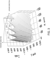
- Fig. 3 is a view illustrating a simulation result when a surface where the amount of change in the frequency by the Doppler effect is the same (hereinafter, referred to as an "equifrequency surface”) is obtained by a simulation, in the case where the sound source S is moved in one direction as described above.
- each axis is meter.
- the wave transmitting array 10 is disposed at an intermediate position (the position where the distance is zero) in the Y-axis direction so that it extends in the X-axis direction.
- the transmission wave is transmitted in the Z-axis direction from the intermediate position in the Y-axis direction. That is, the direction along the Z-axis direction from the intermediate position in the Y-axis direction is the forward direction.
- equifrequency surfaces EP1 to EP5 within a range above the forward direction are illustrated.
- the equifrequency surfaces EP1, EP2, EP3, EP4, and EP5 are surfaces of the frequencies f0-fd1, f0-fd2, f0-fd3, f0-fd4, and f0-fd5, respectively.
- "f0" is the frequency in the forward direction, which is equal to the frequency of the transmission signal supplied to the wave transmitting element.
- fd1 to fd5 have a relationship of fd 1 ⁇ fd2 ⁇ fd3 ⁇ fd4 ⁇ fd5 .
- equifrequency surfaces EP1 to EP5 are illustrated, but a large number of equifrequency surfaces also exist between the equifrequency surfaces EP1 to EP5.
- the frequency of the gap between the equifrequency surfaces EP1 and EP2 transits continuously from f0-fd1 to f0-fd2.
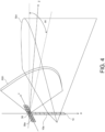
- Fig. 4 is a view schematically illustrating one example of a configuration of the wave transmitting-and-receiving system.
- a wave receiving array 30 having a plurality of receiving elements 30a may be disposed as a configuration of a wave receiving system.
- the wave transmitting array 10 may be disposed so that the wave transmitting elements 10a are lined up along the X-axis.
- the wave receiving array 30 may be disposed at a position immediately above the wave transmitting array 10.
- the array direction of the wave receiving elements 30a and the array direction of the wave transmitting elements 10a may be perpendicular to each other.
- a transmission beam TB1 may be formed forward of the wave transmitting array 10 (in the positive Z-axis direction).
- the transmission wave may be transmitted with a comparatively large directivity from the wave transmitting elements 10a.
- the transmission signals S10 for one sweep are supplied to the wave transmitting elements 10a in the wave transmitting array 10 sequentially from the top, an area where all the transmission waves transmitted from the wave transmitting elements 10a overlap with each other may become an area where all the transmission beams TB1 are formed. In this formation area, a large number of equifrequency surfaces may be generated, as described with reference to Fig. 3 .
- a narrow reception beam RB1 may be formed in the circumferential direction centering on the X-axis. Therefore, the reception signal in the area where the reception beam RB1 intersects with the transmission beam TB1 may be extracted.
- the reception signal at each rotated position may be extracted. Based on the rotated position of the reception beam RB1, a horizontal incoming direction of the reflection wave which is caused by the transmission wave being reflected on a target object may be defined. Further, based on the frequency of the reception signal, the equifrequency surface (see Fig. 3 ) where the reflection wave is generated may be defined.
- a distribution of intensity data of the reception signals in the area where the reception beam RB1 intersects with the transmission beam TB1 may be acquired.
- intensity data (volume data) which are distributed three-dimensionally within all the detection areas in the horizontal direction and the vertical direction can be acquired.
- a signal which is frequency-modulated such as a chirp signal
- a transmission signal such as a chirp signal
- a pulse compression technique using a matched filter to the reception signal, a distance resolution of the target object detection can be raised.
- a window may be applied for each sweep in order to suppress side lobes which are caused in the sweep direction (bearing direction).
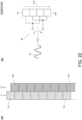
- Fig. 5 is a view illustrating an example application of the window for suppressing the side lobes.
- Fig. 5 an example application of windows when the wave transmitting array 10 is swept twice to generate the transmission pulse is illustrated.
- T11 may be a first sweep period
- T12 may be a second sweep period.
- Numbers 1 to 8 in the upper row of Fig. 5 indicate the numbers of the wave transmitting elements 10a as in Fig. 1(b) .
- a waveform illustrated beside each number schematically illustrates a waveform of a window W1 for every wave transmitting element 10a, which is applied during a period when the wave transmitting element 10a of each number is driven by the transmission signal.
- Waveforms in the middle row of Fig. 5 are waveforms of windows W11 and W12 which are set for each sweep
- a waveform in the lower row of Fig. 5 is a waveform of a window W0 applied to the entire transmission pulse.
- the waveform of each window indicates weighting of the transmission signal.
- the weight may be higher as the waveform of the window is higher.
- the transmission signal may be amplified with a weight which is obtained by superimposing the weights of all the windows. That is, the transmission signal (for example, the chirp signal) which is frequency-modulated over a period from a start time of the sweep period T11 (a start timing of the transmission pulse) to an end time of the sweep period T12 (an end timing of the transmission pulse) may be amplified with the weight which is obtained by superimposing the weights of all the windows.
- the transmission signal amplified by each window may be supplied to each wave transmitting element 10a at the timing of switching of the signal switch 20.
- the side lobes may be suppressed.
- the side lobes caused in the sweep direction may be suppressed by the window W1 in the upper row, and the windows W11 and W12 in the middle row, and the side lobes in the distance direction (time-axis direction) may be suppressed by the window W0 in the lower row.
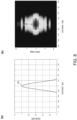
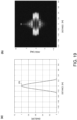
- Fig. 6(a) is a view illustrating a simulation result of the waveform of the transmission wave in the case where the windows are set as illustrated in Fig. 5 , which is obtained by a simulation
- Fig. 6(b) is a view illustrating a result of reception processing of the echo of this transmission wave, which is obtained by a simulation.
- the target object exists at a position of 0 degree in the sweep direction (a position in the forward direction). Further, in these simulations, it is assumed that the sweep is repeated five times to generate the transmission pulse of one detection unit.
- the horizontal axis is a distance in the front-rear direction from the center waveform P0, and the vertical axis is an intensity of the envelope of the transmission wave.
- the horizontal axis is a distance in the front-rear direction from a normal distance position of the target object, and the vertical axis is an angle of the sweep direction with respect to the forward direction. Note that the graph of Fig. 6(a) is standardized considering the peak of the center waveform P0 as 1. Further, although the original drawing of Fig. 6(b) was a color image, this color image is illustrated by a gray scale for convenience.
- a plurality of ripples R1 may occur before and after the center waveform P0, as illustrated in Fig. 6(a) . Therefore, as illustrated in Fig. 6(b) , in the reception processing result, the high-intensity area (broken-line elliptical area) may occur also at distance positions D1 corresponding to the ripples R1, in addition to the normal distance position D0 of the target object.
- an image indicative of the target object may be displayed also at the distance positions D1 corresponding to the ripples R1, in addition to the normal distance position D0 of the target object. Therefore, in the detection image, the position of the target object may not be clearly displayed, but it may become an indication in which a plurality of target object images are overlapped near the normal position of the target object.
- the next sweep may be initiated between the start and the end of one sweep. This prevents an occurrence of a deep valley at the boundary between the window W11 set to one sweep and the window W12 set to the next sweep, and it prevents the occurrence of the ripples R1 as illustrated in Fig. 6(a) .
- Fig. 7 is a view illustrating an example application of the windows in this case.
- a sweep in a sweep period T21 is set between the sweep in the sweep period T11 and the sweep in the sweep period T12.
- the sweep in the sweep period T21 may be started at an intermediate timing of the sweep period T11. Further, the sweep in the next sweep period T12 may be started at an intermediate timing of the sweep period T21.
- a window W21 illustrated by a broken line in the middle row may also be set in the sweep period T21.
- the windows W1, W21, and W0 in the upper row, the middle row, and the lower row corresponding to the sweep period T21 may be applied. That is, the windows W1 in the upper row applied in the sweep period T21 may be eight windows lined up obliquely. Further, the window W21 in the middle row applied in the sweep period T21 may be a window similar to the windows W11 and W12, and the window W0 in the lower row applied in the sweep period T21 may be a part which is cut out from the window W0 in the lower row within the range of the sweep period T21.
- the windows applied in the sweep periods T11 and T12 may be similar to the case of Fig. 5 .
- the transmission signal (for example, a chirp signal) which is frequency-modulated over a period from the start time of the sweep period T11 (the start timing of the transmission pulse) to the end time of the sweep period T12 (the end timing of the transmission pulse) may be amplified with the weight which is obtained by superimposing the weights of all the windows, for each of the sweep periods T11, T12, and T21.
- the transmission signal which is weighted in each window may be supplied to each wave transmitting element 10a during the drive period of each wave transmitting element 10a in each sweep period.
- the side lobes may be suppressed similarly to the case of Fig. 5 .
- the side lobes caused in the sweep direction may be suppressed by the window W1 in the upper row and the windows W11, W12, and W21 in the middle row, and the side lobes in the distance direction may be suppressed by the window W0 in the lower row.
- the window W21 in the middle row of the sweep period T21 is interpolated between the window W11 in the middle row of the sweep period T 11 and the window W12 in the middle row of the sweep period T12, it suppresses the occurrence of the deep valley at the boundary between these windows. Thus, that prevents the occurrence of the ripples R1 as illustrated in Fig. 6(b) .
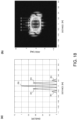
- Figs. 8(a) and 8(b) are each views illustrating a simulation result when the windows are set as illustrated in Fig. 7 .
- Fig. 8(a) illustrates a simulation result of the transmission waveform similar to Fig. 6(a)
- Fig. 8(b) illustrates a simulation result of the reception processing result similar to Fig. 6(b) .
- the target object exists at a position of 0 degree in the sweep direction (the position in the forward direction). Further, also in these simulations, it is assumed that the sweep is repeated five times to generate one transmission pulse.
- a high-intensity area (a broken line elliptical area) may occur near the normal distance position D0 of the target object, without the high-intensity areas which are clearly separated in the distance direction as illustrated in Fig. 6(b) .
- the detection image of the target object it prevents that a plurality of target object images is displayed so as to overlap with each other near the normal distance position of the target object, and the image indicative of the target object is displayed near the normal distance. Therefore, in the detection image, the position of the target object can be displayed more clearly, and the accuracy of the image indicative of the target object can be raised.
- Fig. 9 is a view illustrating a configuration of the signal switch, when starting the next sweep in the middle of one sweep, as illustrated in Fig. 7 .
- the first signal switch 21 and the second signal switch 22 may be each comprised of a demultiplexer, for example.
- the first signal switch 21 is used for odd-numbered sweeps
- the second signal switch 22 is used for even-numbered sweeps.
- a first transmission signal S11 may be supplied to a terminal T1
- a second transmission signal may be supplied to a terminal T2.
- Each transmission signal may be a signal which is obtained by weighting the transmission signal (for example, a chirp signal), which is frequency-modulated over the period from the start timing of the transmission pulse to the end timing of the transmission pulse by each window in Fig. 7 , for example, for each sweep period, as described above.
- a chirp signal for example, a chirp signal
- the second signal switch 22 may connect the terminal T2 to the first wave transmitting element 10a from the top.
- the sweep of the sweep period T21 may be started in the middle of the sweep period T11. Therefore, it prevents as described above that the ripples R1 occur in the transmission wave.
- the repeating period of the sweep may become half as compared with the case of Fig. 5 . Therefore, the chirp bandwidth can be doubled, and the distance resolution of the target object detection can be raised.
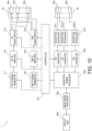
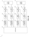
- Fig. 10 is a block diagram illustrating a concrete configuration of a target object detecting device 1.
- the target object detecting device 1 may be provided with the above-described wave transmitting array 10 as a configuration of the wave transmitting system.
- the wave transmitting array 10 may have a similar configuration to Fig. 9 .
- the target object detecting device 1 may include, as a configuration for supplying the transmission signal to each wave transmitting element 10a of the wave transmitting array 10, a first transmission signal generator 111 and a second transmission signal generator 121, a first transmission amplifier 112 and a second transmission amplifier 122, and a first signal switch 113 and a second signal switch 123.
- the first transmission signal generator 111 may generate the first transmission signal S11 according to the control from a controller 101.
- the first transmission signal S11 may be a signal used for the odd-numbered sweep as described above, and may be a signal obtained by weighting the frequency-modulated transmission signal for one pulse with each window applied in the odd-numbered sweep period.
- the second transmission signal generator 121 may generate the second transmission signal S12 according to the control from the controller 101. Further, the second transmission signal S 12 may be a signal used for the even-numbered sweep as described above, and may be a signal obtained by weighting the frequency-modulated transmission signal for one pulse with each window applied in the even-numbered sweep period.
- the first transmission amplifier 112 may amplify the first transmission signal S 11 inputted from the first transmission signal generator 111 according to the control from the controller 101.
- the first signal switch 113 may sequentially supply the first transmission signal S 11 to the plurality of wave transmitting elements 10a included in the wave transmitting array 10 according to the control from the controller 101.
- the first signal switch 113 may have a similar configuration to the first signal switch 21 of Fig. 9 .
- the first signal switch 113 may be comprised of a demultiplexer, for example.
- the second transmission amplifier 122 may amplify the second transmission signal S 12 inputted from the second transmission signal generator 121 according to the control from the controller 101.
- the second signal switch 123 may sequentially supply the second transmission signal S 12 to the plurality of wave transmitting elements 10a included in the wave transmitting array 10 according to the control from the controller 101.
- the second signal switch 123 may have a similar configuration to the second signal switch 22 of Fig. 9 .
- the second signal switch 123 may be comprised of a demultiplexer, for example.
- the controller 101 may include a processing circuit, such as a CPU (Central Processing Unit), and a storage medium, such as a ROM (Read Only Memory), a RAM (Random Access Memory), and a hard disk drive.
- a processing circuit such as a CPU (Central Processing Unit)
- a storage medium such as a ROM (Read Only Memory), a RAM (Random Access Memory), and a hard disk drive.
- the controller 101 may be comprised of an integrated circuit, such as an FPGA
- the controller 101 may control the first transmission signal generator 111 and the second transmission signal generator 121, the first transmission amplifier 112 and the second transmission amplifier 122, and the first signal switch 113 and the second signal switch 123 so that the sweep of the wave transmitting array 10 by the second transmission signal S12 is started at a timing before the sweep period of the wave transmitting array 10 by the first transmission signal S11 ends as described above.
- the sweep period of the wave transmitting array 10 by the first transmission signal S11 may partially overlap with the sweep period of the wave transmitting array 10 by the second transmission signal S12.
- the controller 101 performs a transmission control so that the sweep of the wave transmitting array 10 by the second transmission signal S12 is started at an intermediate timing of the sweep period of the wave transmitting array 10 by the first transmission signal S11.
- the controller 101 may apply each window illustrated in Fig. 7 to the first transmission signal S11 and the second transmission signal S12. Therefore, the side lobes and the ripples may be suppressed as described above.
- the target object detecting device 1 may be provided with the above-described wave receiving array 30 as a configuration of the wave receiving system.
- the wave receiving array 30 may have a similar configuration to Fig. 4 .
- "k" pieces of wave receiving elements 30a may be disposed in the wave receiving array 30.
- the reception signal may be outputted from the wave receiving elements 30a to channels CH1 to CHk corresponding to the respective wave receiving elements 30a.
- the target object detecting device 1 may include a plurality of reception processors 201, a plurality of A/D converters 202, a reception signal processor 203, and an image signal processor 204, as a configuration for processing the reception signal outputted from each wave receiving element 30a of the wave receiving array 30 and generating the detection image.
- the plurality of reception processors 201 may be connected to the channels CH1 to CHk, respectively. Each reception processor 201 may perform, for the inputted reception signal, processing for removing an unnecessary band, processing for amplifying the reception signal to a level suitable for an A/D conversion, processing for removing a signal component of a band of more than half of the sampling period of the A/D conversion, etc.
- the plurality of A/D converters 202 may be associated with the plurality of reception processors 201, respectively. Each A/D converter 202 may convert the analog reception signal inputted from the corresponding reception processor 201 into a digital signal at a given sampling period.
- the reception signal processor 203 may process the reception signals of the channels CH1 to CHk respectively inputted from the plurality of A/D converters 202 to calculate the intensity data (volume data) of the reception signals which are distributed three-dimensionally over the detection area.
- the reception signal processor 203 may be comprised of a single integrated circuit (FPGA etc.) together with the controller 101.
- the image signal processor 204 may process the intensity data (volume data) inputted from the reception signal processor 203 to generate image data for imaging a state of the target object within the detection area.
- the image signal processor 204 may be comprised of a CPU, for example.
- the display unit 205 may be comprised of a monitor etc., which displays a detection image according to the image data inputted from the image signal processor 204.
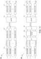
- Fig. 11(a) is a functional block diagram illustrating one example of a configuration of the reception signal processor 203.
- the reception signal processor 203 may include a processing circuit and a storage medium.
- the reception signal processor 203 may perform a function of each functional block illustrated in Fig. 11(a) by the program stored in the storage medium.
- a part of the functions of Fig. 11(a) may be realized not by software but by hardware using a logic circuit.
- the reception signal processor 203 may include a plurality of digital filters 211, a buffer 212, a plurality of matched filters 213, and a plurality of beamformers 214.
- the plurality of digital filters 211 may be provided corresponding to the plurality of A/D converters 202 of Fig. 10 .
- the digital filter 211 may be a filter sharper than the filtering function in the reception processor 201 of Fig. 10 , and remove a signal of an unnecessary band in the reception signal.
- the buffer 212 may temporarily hold the reception signals of the channels CH1 to CHk respectively outputted from the plurality of digital filters 211.
- the buffer 212 may hold in a time-series manner the reception signals per unit pulse period during which the plurality of wave transmitting elements 10a of the wave transmitting array 10 are swept a plurality of times.
- the buffer 212 may sequentially supply the reception signals of the unit pulse period to the plurality of matched filters 213.
- the buffer 212 may erase the reception signals of the unit pulse period.
- the plurality of matched filters 213 may carry out a pulse-compression of the inputted reception signals of the unit pulse period of the channels CH1 to CHk, for each equifrequency surface.
- the matched filter 213 may be provided for every equifrequency surface. That is, the equifrequency surfaces may be defined corresponding to the number of matched filters 213. The resolution of the reception signal in the stacking direction of the equifrequency surfaces may increase as the number of matched filters 213 increases.
- a parameter value according to the ideal transmission waveform of the corresponding equifrequency surface may be set to each matched filter 213.
- the equifrequency surface associated with each matched filter 213 may be preferred to be an equifrequency surface which satisfies the above-described Formula (5).
- the matched filter 213 may generate a signal (hereinafter, referred to as an "equifrequency reception signal") obtained by carrying out a pulse compression of the reception signal for the unit pulse period of the channels CH1 to CHk with the ideal waveform set for itself, and supply it to the beamformer 214.
- the plurality of beamformers 214 may be provided corresponding to the plurality of matched filters 213.
- the beamformer 214 may form the reception beam RB1 by beamforming based on a phase control or a delay control, and separate the equifrequency reception signal in the ⁇ 1 direction in Fig. 4 at a given resolution. Therefore, the equifrequency reception signals within an area where the reception beam RB1 intersects with the equifrequency surface defined by the matched filter 213 may be acquired. That is, the equifrequency reception signals within the crossing area where a first equifrequency surface S 1 intersects with the reception beam RB1 in each direction (the ⁇ 1 direction in Fig. 4 ) parallel to the horizontal plane may be acquired from the top beamformer 214.
- the obtained equifrequency reception signal may change in the intensity on the time axis according to the intensity of the reflection wave from the crossing area.
- This time axis may correspond to a distance from the wave receiving array 30 in the crossing area. Therefore, by mapping each intensity on the time axis in the crossing area, at a corresponding distance position from the wave receiving array 30, a distribution of the intensity data on the crossing area may be acquired.
- the volume data in which the intensity data is distributed three-dimensionally over the detection area may be acquired.
- Fig. 11(b) is a functional block diagram illustrating another example of the configuration of the reception signal processor 203.
- the reception signal of each channel is frequency-converted by an FFT (Fast Fourier Transform) 221, it may be pulse-compressed by a matched filter 222 for every channel within the frequency range.
- the matched filter 222 may perform a pulse compression for every equifrequency surface similarly to the case of Fig. 11(a) .
- the pulse-compressed signal of each channel may be converted into a time domain by an IFFT (Inverse Fourier Transform) 223.
- the equifrequency surface reception signal may be generated for every equifrequency surface.
- the generated equifrequency reception signal of each equifrequency surface may be outputted to the corresponding beamformer 214.
- the subsequent processing may be similar to the case of Fig. 11(a) .
- the volume data in which the intensity data are distributed three-dimensionally over the detection area may be acquired.
- the pulse compression by the matched filter 222 since the pulse compression by the matched filter 222 is performed in the frequency domain, it can reduce the operation amount of the pulse compression as compared to the example configuration of Fig. 11(a) .
- the matched filter for acquiring the equifrequency reception signal can be set more finely than in the example configuration of Fig. 11(a) . Therefore, the number of equifrequency surfaces to be processed can be increased, and the resolution of the equifrequency reception signal in a stacking direction of the equifrequency surfaces can be raised.
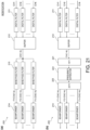
- Figs. 12(a) and 12(b) are flowcharts illustrating wave transmission processing performed by the controller 101 of Fig. 10 . This processing may be continuously performed during detection operation, and it may be ended according to the termination of the detection operation.
- Fig. 12(a) illustrates wave transmission processing for the odd-numbered sweep using the first signal switch 113
- Fig. 12(b) illustrates wave transmission processing for the even-numbered sweep using the second signal switch 123.
- the controller 101 may perform a first sweep using the first signal switch 113 (S112).
- the controller 101 may cause the first transmission signal generator 111 to generate the first transmission signal S11, and control the first signal switch 113 to switch the wave transmitting element 10a which is the supply destination of the first transmission signal S11 sequentially from the first wave transmitting element 10a to the final wave transmitting element 10a.
- the controller 101 may determine whether the control to be performed for the wave transmission for one pulse is finished (that is, whether the odd-numbered sweep has been repeated for the number of times for one pulse) (S114).
- Step S114 the controller 101 may return the sweep position back to the first wave transmitting element 10a (S115), and repeat the first sweep (S112). Thus, if the odd-numbered sweep has been repeated for the preset number of times (S114: YES), the controller 101 may end the odd-numbered sweep control using the first signal switch 113.
- the controller 101 may perform a second sweep using the second signal switch 123 (S122).
- the controller 101 may cause the second transmission signal generator 121 to generate the second transmission signal S 12, and control the second signal switch 123 to switch the wave transmitting element 10a which is the supply destination of the second transmission signal S12 sequentially from the first wave transmitting element 10a to the final wave transmitting element 10a.
- the controller 101 may determine whether the control to be performed for the wave transmission for one pulse is finished (that is, whether the even-numbered sweep has been repeated for the number of times for one pulse) (S124).
- Step S124 the controller 101 may return the sweep position back to the first wave transmitting element 10a (S125), and repeat the second sweep (S122). Thus, if the even-numbered sweep has been repeated for the preset number of times (S124: YES), the controller 101 may end the even-numbered sweep control using the second signal switch 123.
- the transmission beam TB1 having a large number of equifrequency surfaces may be formed.
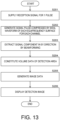
- Fig. 13 is a flowchart illustrating processing for processing the reception signal and displaying the detection image.
- the reception signals for the unit pulse period may be supplied to the plurality of matched filters 213 from the buffer 212, respectively (S201).
- Each matched filter 213 may generate the signal (equifrequency reception signal) which is obtained by carrying out the pulse compression of the inputted reception signal of each channel with the ideal waveform of the equifrequency surface set for itself, and supply it to the corresponding beamformer 214 (S202).
- the beamformer 214 may extract the signal component in each horizontal direction ( ⁇ 1 direction) from the inputted equifrequency reception signal by the beamforming (S203). Therefore, the distribution of the intensity data in which the intensity data of the reception signal are mapped in each equifrequency surface may be acquired.
- the reception signal processor 203 may integrate the intensity data from all the beamformers 214, and constitute the volume data in which the intensity data are distributed three-dimensionally over the detection area (S204).
- the reception signal processor 203 may supply the volume data to the image signal processor 204.
- the image signal processor 204 may process the volume data to generate the image data for indicating the detection situation of the target objects within the detection area, and supply the generated image data to the display unit 205 (S205).
- the display unit 205 may display the image based on the inputted image data (S206). Thus, the detection situation of the target objects within the detection area may be displayed.
- the controller 101 may repeatedly perform the processing of Steps S201 to S206, each time the transmission pulse is transmitted by the processing of Figs. 12(a) and 12(b) .
- Fig. 14 is a view schematically illustrating a configuration when the above-described target object detecting device 1 is used as a sonar which detects an underwater target object.
- a transducer 300 may be installed at the bottom of a ship 2.
- the transducer 300 may include the wave transmitting array 10 and the wave receiving array 30.
- the wave transmitting array 10 may transmit a transmission wave underwater by the above-described processing.
- a sound wave for example, an ultrasonic wave
- the transmission beam TB1 in which the equifrequency surfaces are stacked in the angular direction may be formed.
- configurations other than the wave transmitting array 10, the wave receiving array 30, and the display unit 205 may be provided to a control device installed in a pilothouse 2a of the ship 2.
- the display unit 205 may be installed in the pilothouse 2a, separately from the control device.
- the display unit 205 may be integrated with the control device.
- the detection image indicative of the situation of a water bottom 3 and a school of fish 4 may be displayed on the display unit 205. Therefore, a user can grasp the underwater situation.
- four transducers 300 which are respectively oriented forward, rearward, leftward, and rightward may be installed in the ship bottom.
- the configurations of the wave transmitting system and the wave receiving system of Fig. 10 may be prepared for every transducer 300. Therefore, the detection image all around the ship can be displayed on the display unit 205.
- a transducer 400 may be installed in a side wall of the pilothouse 2a.
- the transducer 400 may include the wave transmitting array 10 and the wave receiving array 30.
- the wave transmitting array 10 may transmit the transmission wave in the air by the above-described processing.
- a radio wave may be transmitted as the transmission wave.
- the configuration of the circuitry may be installed in the pilothouse 2a similarly to the case of the sonar.
- the detection image indicative of the situation of obstacles and a flock of birds may be displayed on the display unit 205. Therefore, the user can grasp the situation in the air.
- the transducer 400 may be installed in each of the front, rear, right, and left side surfaces of the pilothouse 2a. In this case, the configurations of the wave transmitting system and the wave receiving system of Fig. 10 may be prepared for every transducer 400. Therefore, the detection image of the space all around the ship 2 can be displayed on the display unit 205.
- the wave transmitting element 10a to which the first transmission signal S 11 is supplied being switched from the element n to the element n+1 in the wave transmitting array 10 by the first signal switch 21, the wave transmission source of the transmission wave may move in the array direction of the wave transmitting elements 10a.
- the frequency of the transmission beam TB1 may change in the moving direction of the wave transmission source by the Doppler effect to form the plurality of equifrequency surfaces in the transmission beam TB1. Therefore, by extracting the signal corresponding to each equifrequency surface from the reception signals generated from the wave receiving element 30a, the reception signal based on the reflection wave from each equifrequency surface (equifrequency reception signal) can be acquired.
- the wave transmitting element 10a to which the second transmission signal S 12 is supplied may be switched from the element m to the element m+1 inside the wave transmitting array 10 by the second signal switch 22 of Fig. 9 .
- the sweep of the wave transmitting array 10 by the first signal switch 21 partially may overlap with the sweep of the wave transmitting array 10 by the second signal switch 22, and it prevents that the ripple occurs in the transmission waveform and the reception processing result (equifrequency reception signal), as illustrated in Figs. 8(a) and 8(b) . Therefore, the detection accuracy of the target object can be raised.
- the target object in each equifrequency surface can be detected with sufficient accuracy by the simple configuration in which the wave transmitting element 10a to which the first transmission signal S11 and the second transmission signal S 12 are supplied is switched inside the wave transmitting array 10.
- the element n+1 may be adjacent to the element n
- the element m+1 may be adjacent to the element m.
- the wave transmitting element 10a to which the first transmission signal S 11 is supplied may be switched from the element n+1 to the element n+2 which is adjacent to the element n+1
- the wave transmitting element 10a to which the second transmission signal S 12 is supplied may be switched from the element m+1 to an element m+2 which is adjacent to the element m+1.
- the wave transmitting array 10 is provided with "P" pieces of wave transmitting elements 10a and P is an even number, it may be preferred that "(P/2)-1" pieces of wave transmitting elements 10a are included between the element n and the element m, and if P is an odd number, it may be preferred that "(P-1)/2" pieces, or " ⁇ (P-1)/2 ⁇ -1” pieces of wave transmitting elements 10a are included between the element n and the element m.
- each sweep can be overlapped by 1/2 cycle, and the ripple which is generated in the transmission wave and the reception processing result can be suppressed more effectively. Further, in this case, as compared with the case of Fig. 5 , the repeating period of the sweep is half, and therefore, the chirp bandwidth can be doubled and the distance resolution of the target object detection can be raised.
- the wave transmitting array 10 is provided with P pieces of wave transmitting elements 10a from wave transmitting element 1 to wave transmitting element P, when the element n+1 corresponds to the wave transmitting element 10a beyond the wave transmitting element P, the first signal switch 21 may switch the wave transmitting element 10a to which the first transmission signal S 11 is supplied from the wave transmitting element P to the wave transmitting element 1, and when the element m+1 corresponds to the wave transmitting element 10a beyond the wave transmitting element P, the second signal switch 22 may switch the wave transmitting element 10a to which the second transmission signal S 12 is supplied from the wave transmitting element P to the wave transmitting element 1.
- the wave transmitting array 10 may be repeatedly swept by the first transmission signal S11 and the second transmission signal S12. Therefore, the transmitting energy for one pulse can be raised, and the detectable distance range can be expanded.
- the first transmission signal S11 may be a frequency-modulated signal
- the second transmission signal S12 may be a frequency-modulated signal.
- a first part of the first transmission signal S11 may be supplied to the element n, and a second part of the first transmission signal S11 different from the first part may be supplied to the element n+1, and a first part of the second transmission signal S12 may be supplied to the element m, and a second part of the second transmission signal S12 different from the first part of the second transmission signal S12 may be supplied to the element m+1.
- the first transmission signal S11 and the second transmission signals S12 are the frequency-modulated signals, such as the chirp signals, the parts of the signal waveform supplied to the element n and the element n+1 may be different, and the parts of the signal waveform supplied to the element m and the element m+1 may be different.
- the reception signal processor 203 may be provided with the configuration (matched filters 213 and 222) which extracts, based on the frequency component of the reception signal, the reception signal (equifrequency reception signal) based on the reflection wave from the corresponding equifrequency surface corresponding to the frequency. Therefore, the equifrequency reception signal corresponding to each equifrequency surface can be smoothly acquired.
- the reception beam RB1 generated based on the reception signal which is generated from each wave receiving element 30a intersects with the transmission beam TB1 generated by the wave transmitting array 10. Therefore, the distribution of the intensity data based on the intensity of the reflection wave can be calculated within the area where the reception beam RB1 intersects with the transmission beam TB1 (equifrequency surface). Therefore, by changing the orientation of the reception beam by beamforming within the detection area, the intensity data which are distributed three-dimensionally over the detection area can be constituted.
- first transmission signal S11 and the second transmission signal S 12 are supplied to one wave transmitting element 10a, a plurality of wave transmitting elements 10a may be grouped, and the first transmission signal S 11 and the second transmission signal S 12 may be supplied to each group.
- Fig. 15 is a view illustrating a configuration in the case where the first transmission signal S11 and the second transmission signal S 12 are supplied to each group of wave transmitting elements 10a.
- each group may include two wave transmitting elements 10a.
- a group G1 may be constituted from the top two wave transmitting elements 10a, and a group G2 may be constituted from the top second and third wave transmitting elements 10a.
- the two wave transmitting elements 10a included in the adjacent groups may be offset in the up-down direction by one element.
- seven groups from the group G1 to a group G7 may be constituted.
- the first signal switch 21 and the second signal switch 22 may be provided with one input terminal and two output terminals, and the two output terminals may be connected simultaneously to the wave transmitting elements 10a of each group. Therefore, the first transmission signal S 11 or the second transmission signal S 12 may be simultaneously supplied to the wave transmitting elements 10a of each group.
- the first signal switch 21 may switch the group to which the first transmission signal S 11 is supplied from a group g to a group g+1
- the second signal switch 22 may switch the group to which the second transmission signal S 12 is supplied from a group h to a group h+1.
- the supply destination of the first transmission signal S11 or the second transmission signal S 12 may be switched sequentially to the next group. Therefore, the sweep of the wave transmitting array 10 may be performed per group.
- a circuit configuration similar to Fig. 10 and Figs. 11(a) and 11(b) may be applied.
- the configurations of the first signal switch 113 and the second signal switch 123 of Fig. 10 , and the wave transmitting array 10 may be replaced with the configuration of Fig. 15 .
- the controller 101 may control each part of the wave transmitting system so that the sweep by the first signal switch 113 and the sweep by the second signal switch 123 are partially overlapped with each other.
- the controller 101 controls each part of the wave transmitting system so that the sweep by the first signal switch 113 and the sweep by the second signal switch 123 are overlapped with each other substantially by half cycle.
- the wave transmission source of the transmission wave may be moved by switching the transmission destination of the transmission signal per group. Therefore, similarly to the above embodiment, the transmission beam can be changed in the frequency by the Doppler effect. Further, since the sweep by the first signal switch 113 and the sweep by the second signal switch 123 are partially overlapped, it prevents that the ripple occurs in the transmission wave, similarly to the above embodiment. Further, according to this modification, since the transmission wave is transmitted per group, the output and the directional gain of the transmission wave can be raised.
- one group is constituted by two wave transmitting elements 10a
- one group may be constituted by three or more wave transmitting elements 10a.
- the wave transmission source of the transmission wave may be moved by switching the transmission destination of the transmission signal per group.
- the wave transmission may be performed using one wave transmitting array 10.
- the wave transmission may be performed using two wave transmitting arrays.
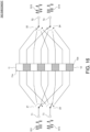
- Fig. 16 is a view illustrating a configuration for transmitting waves using the two wave transmitting arrays.
- the wave transmitting system may include a first wave transmitting array 11, a second wave transmitting array 12, a first signal switch 21, a second signal switch 22, a third signal switch 23, and a fourth signal switch 24.
- the first wave transmitting array 11 may be constituted so that a plurality of first wave transmitting elements 11a are lined up in a single row.
- the second wave transmitting array 12 may be constituted so that a plurality of second wave transmitting elements 12a are lined up in a single row.
- the second wave transmitting element 12a may be disposed between adjacent first wave transmitting elements 11a.
- the first transmission signal S11 may be supplied to the terminal T1 of the first signal switch 21, and the second transmission signal S12 may be supplied to the terminal T2 of the second signal switch 22.
- the first signal switch 21 and the second signal switch 22 may switch the first wave transmitting elements 11a which are used as the supply destinations of the first transmission signal S11 and the second transmission signal S 12 in the first transmitting array 11, respectively.
- a third transmission signal S 13 may be supplied to a terminal T3 of the third signal switch 23, and a fourth transmission signal S 14 may be supplied to a terminal T4 of the fourth signal switch 24.
- the third signal switch 23 and the fourth signal switch 24 may switch the second wave transmitting elements 12a which are used as the supply destinations of the third transmission signal S13 and the fourth transmission signal S14 in the second wave transmitting array 12, respectively.
- the third signal switch 23 may be controlled so that the wave transmission is performed by the second wave transmitting element 12a of the second wave transmitting array 12 which is sandwiched between the element n and the element n+1, at the timing when the first wave transmitting element 11a which is the supply destination of the first transmission signal S11 is switched from the element n to the element n+1 by the first signal switch 21 in the first wave transmitting array 11.
- the fourth signal switch 24 may be controlled so that the wave transmission is performed by the second wave transmitting element 12a of the second wave transmitting array 12 which is sandwiched between the element m and the element m+1, at the timing when the first wave transmitting element 11a which is the supply destination of the second transmission signal S12 is switched from the element m to the element m+1 by the second signal switch 22 in the first wave transmitting array 11.
- a gap between the wave transmissions by the first transmission signal S11 may be interpolated by the wave transmission by the third transmission signal S13, and a gap between the wave transmissions by the second transmission signal S12 may be interpolated by the wave transmission by the fourth transmission signal S14.
- Fig. 17 is a view illustrating an example application of the windows, according to the second embodiment.
- the sweep in the sweep period T21 may be set between the sweep in the sweep period T11 and the sweep in the sweep period T12. Also in this case, the sweep in the sweep period T21 may be started near the middle of the sweep period T11. Further, the sweep in the next sweep period T12 may be started near the middle of the sweep period T21.
- the windows W11, W12, and W21 illustrated by a broken line in the middle row may be set in the sweep periods T11, T12, and T21, respectively, and the window W0 may be set in the entire transmission pulse.
- a window W1a illustrated by a solid line may be a window applied during the period where the first transmission signal S11 is supplied to the first wave transmitting element 11a by the first signal switch 21 of Fig. 16
- a window W1b illustrated by a broken line may be a window applied during the period where the third transmission signal S 13 is supplied to the second wave transmitting element 12a by the third signal switch 23 of Fig. 16
- a window W2a illustrated by a solid line may be a window applied during the period where the second transmission signal S12 is supplied to the first wave transmitting element 11a by the second signal switch 22 of Fig. 16
- a window W2b illustrated by a broken line may be a window applied during the period where the fourth transmission signal S14 is supplied to the second wave transmitting element 12a by the fourth signal switch 24 of Fig. 16 .
- the weighting which is obtained by superimposing the window W1a, the window W11, and the window W0 may be applied to the first transmission signal S11, and the weighting which is obtained by superimposing the window W1b, the window W11, and the window W0 may be applied to the third transmission signal S13.
- a similar application may be performed in the sweep period T12.
- the weighting which is obtained by superimposing the window W2a, the window W21, and the window W0 may be applied to the second transmission signal S12, and the weighting which is obtained by superimposing the window W2b, the window W21, and the window W0 may be applied to the fourth transmission signal S14.
- the windows applied to the first transmission signal S11, the second transmission signal S12, the third transmission signal S13, and the fourth transmission signal S14, respectively, may be applied to the transmission signal (for example, a chirp signal) which is frequency-modulated over a period from the start time of the sweep period T11 (the start timing of the transmission pulse) to the end time of the sweep period T12 (the end timing of the transmission pulse) to generate the first transmission signal S11, the second transmission signal S12, the third transmission signal S13, and the fourth transmission signal S14.
- the transmission signal for example, a chirp signal
- the first transmission signal S11 may be generated by applying the windows W1a, W11, and W0 of Fig. 17 to the transmission signal which is changed in the frequency.
- the second transmission signal S12 may be generated by applying the windows W2a, W21, and W0 of Fig. 17 to the transmission signal which is changed in the frequency.
- the third transmission signal S13 may be generated by applying the windows W1b, W11, and W0 of Fig. 17 to the transmission signal which is changed in the frequency.
- the fourth transmission signal S14 may be generated by applying the windows W2b, W21, and W0 of Fig. 17 to the transmission signal which is changed in the frequency.
- Fig. 18(a) is a view illustrating a simulation result according to a comparative example when a waveform of the transmission wave is obtained by a simulation
- Fig. 18(b) is a view illustrating a result of carrying out reception processing of the echo of this transmission wave, which is obtained by a simulation, according to the comparative example.
- the sweep in the sweep period T21 and the setup of the windows W2a, W2b, and W21 in Fig. 17 are omitted. Further, in the comparative example, it is assumed that the target object exists at the position of 0 degree in the sweep direction (the position in the forward direction). In the simulation of Figs. 18(a) and 18(b) , it is assumed that the sweep is repeated five times to generate the transmission pulse of one detection unit.
- the vertical axis and the horizontal axis of each graph of Figs. 18(a) and 18(b) are the same as the vertical axis and the horizontal axis of each graph of Figs. 6(a) and 6(b) .
- a plurality of ripples R1 occur before and after the center waveform P0.
- a high-intensity area (a broken line elliptical area) occurs also at the distance positions D1 corresponding to the ripples R1, in addition to the normal distance position D0 of the target object.
- an image indicative of the target object is displayed also at the distance positions D1 corresponding to the ripples R1, in addition to the normal distance position D0 of the target object.
- Fig. 19(a) is a view illustrating a simulation result according to the second embodiment when a waveform of the transmission wave is obtained by a simulation
- Fig. 19(b) is a view illustrating a result of carrying out reception processing of the echo of this transmission wave, which is obtained by a simulation, according to the second embodiment.
- the simulation results of Figs. 19(a) and 19(b) are those when the sweep period and the windows are set as illustrated in Fig. 17 . That is, in this simulation, unlike the above comparative example, the sweep may be performed also in the sweep period T21 between the sweep periods T11 and T12, and the windows W2a, W2b, and W21 may be set to this sweep period T21.
- a high-intensity area (a broken line elliptical area) may occur only at the normal distance position D0 of the target object.
- the high-intensity area may be concentrated more densely at the normal distance position, as compared with Fig. 8(b) .
- an image indicative of the target object may be displayed only at the normal distance position of the target object. Therefore, according to the sweeping method of the second embodiment, the position of the target object can be displayed more clearly in the detection image, and the accuracy of the image indicative of the target object can be raised.
- Fig. 20 is a block diagram illustrating a concrete configuration of the target object detecting device 1 according to the second embodiment.
- Fig. 20 For convenience, only the configuration of the wave transmitting system is illustrated in Fig. 20 .
- the configuration of the wave receiving system of the target object detecting device 1 may be similar to that of Fig. 10 .
- the target object detecting device 1 may include the first transmission signal generator 111, the second transmission signal generator 121, a third transmission signal generator 131, and a fourth transmission signal generator 141 which generate the first transmission signal S11, the second transmission signal S12, the third transmission signal S13, and the fourth transmission signal S 14, respectively, which are described above.
- the first transmission signal S11, the second transmission signal S12, the third transmission signal S13, and the fourth transmission signal S14 which are generated by the first transmission signal generator 111, the second transmission signal generator 121, the third transmission signal generator 131, and the fourth transmission signal generator 141 may be respectively amplified by the first transmission amplifier 112, the second transmission amplifier 122, a third transmission amplifier 132, and a fourth transmission amplifier 142, and then may be supplied to the first signal switch 113, the second signal switch 123, a third signal switch 133, and a fourth signal switch 143.
- the first signal switch 113, the second signal switch 123, the third signal switch 133, and the fourth signal switch 143 may have similar configurations to the first signal switch 21, the second signal switch 22, the third signal switch 23, and the fourth signal switch 24, respectively, of Fig. 16 .
- the first signal switch 113 and the second signal switch 123 may switch the first wave transmitting elements 11a which are used as the supply destinations of the first transmission signal S11 and the second transmission signal S12 in the first wave transmitting array 11, respectively, as described above.
- the third signal switch 133 and the fourth signal switch 143 may switch the second wave transmitting elements 12a which are used as the supply destinations of the third transmission signal S13 and the fourth transmission signal S14 in the second wave transmitting array 12, respectively, as described above.
- the first transmission signal S11, the second transmission signal S12, the third transmission signal S13, and the fourth transmission signal S14 which are supplied to the respective wave transmitting elements may be weighted as described above by the windows illustrated in Fig. 17 in the first transmission signal generator 111, the second transmission signal generator 121, the third transmission signal generator 131, and the fourth transmission signal generator 141, respectively.
- a parameter value of each matched filter 213 illustrated in Fig. 11(a) may be changed according to the generating method illustrated in Fig. 17 . Also in this case, the parameter according to an ideal transmission wave in each equifrequency surface may be applied to each matched filter 213.
- the side lobes may be suppressed by applying each window illustrated in Fig. 17 .
- the side lobes may be suppressed by applying each window illustrated in Fig. 17 .
- the gap between the wave transmissions by the first transmission signal S11 may be interpolated by the wave transmission by the third transmission signal S13, and the gap between the wave transmissions by the second transmission signal S12 may be interpolated by the wave transmission by the fourth transmission signal S14.
- the element n+1 may be adjacent to the element n
- the element m+1 may be adjacent to the element m
- the element n of the first wave transmitting array 11 may be adjacent to the element n of the second wave transmitting array 12
- the element m of the first wave transmitting array 11 may be adjacent to the element m of the second wave transmitting array 12.
- the transmission wave based on the third transmission signal S13 may be transmitted from the element n in the second wave transmitting array 12.
- the transmission wave based on the fourth transmission signal S14 may be transmitted from the element m in the second wave transmitting array 12.
- the present disclosure is not limited to the configurations of the above embodiment and the second embodiment. Further, the embodiments of the present disclosure may be changed variously to have a configuration other than the above configurations.
- the beamforming then separates the signal into the signal in each direction, but the beamforming may first separate the reception signal into the signal in each direction and then the pulse compression may be performed by the matched filter to the separated signal in each direction.
- the first transmission signal S11 and the second transmission signal S12 before the window is applied are the same signals as the third transmission signal S13 and the fourth transmission signal S14 before the window is applied, the first transmission signal S11 and the second transmission signal S12 before the window is applied may be different signals from the third transmission signal S13 and the fourth transmission signal S14 before the window is applied, as long as the unnecessary frequency component of the transmission wave can be suppressed.
- the frequency of the career signal may be constant.
- the configuration of the reception signal processor 203 may be changed as illustrated in Figs. 21(a) and 21(b) . That is, in the configuration of Fig. 21(a) , the matched filter 213 of Fig. 11(a) may be changed into a band pass filter 215. Each band pass filter 215 may extract the frequency component of the corresponding equifrequency surface from the reception signal of each channel, and output it to the subsequent beamformer 214.
- the matched filter 222 of Fig. 11(b) may be changed into a frequency extractor 224.
- An FFT 211 may calculate a frequency spectrum from the reception signal of each channel.
- the frequency extractor 224 may extract the frequency component of the corresponding equifrequency surface from the calculated frequency spectrum of each channel.
- the extracted frequency component of each equifrequency surface may be converted into a signal of the time domain by an IFFT 223, and be outputted to the subsequent beamformer 214.
- the timing at which the first wave transmitting elements 11a used as the supply destinations of the first transmission signal S11 and the second transmission signal S12 are switched, and the timing at which the second wave transmitting elements 12a used as the supply destinations of the third transmission signal S13 and the fourth transmission signal S14 are switched are not limited to the timing illustrated in Fig. 17 , but they may be other timings, as long as the unnecessary frequency component which occurs in the transmission wave can be suppressed.
- the configurations of the first wave transmitting array 11 and the second wave transmitting array 12 are not limited to the configuration of Fig. 16 , but they may be other configurations, as long as the change in the frequency based on the Doppler effect may be caused in the transmission beam TB1.
- the first wave transmitting array 11 and the second wave transmitting array 12 may be constituted so that the second wave transmitting element 12a may be positioned in the side of the boundary between two adjacent first wave transmitting elements 11a.
- the first transmission signal S11 and the second transmission signal S12, and the third transmission signal S13 and the fourth transmission signal S14 may be supplied to the corresponding wave transmitting elements of the first wave transmitting array 11 and the second wave transmitting array 12 at the timing similar to the case of Fig. 17 . Therefore, the unnecessary frequency component which is generated on the transmission wave can be suppressed.
- the method of grouping the wave transmitting elements 10a is not limited to the method of Fig. 15 , but it may be other methods, as long as the wave transmission source can be moved in one direction.
- the plurality of wave transmitting elements 10a may be grouped into a plurality of groups, and the supply destinations of the transmission signal S1 may be switched from one group to another.
- the wave transmission source can be moved in the moving direction D10, the change in the frequency based on the Doppler effect can be caused in the transmission beam TB1. Further, since the transmission wave is transmitted per group, the output of the transmission wave can be increased.
- the number of wave transmitting elements 10a grouped is not limited to two, but may be three or more.
- the number of wave transmitting elements is not limited to the numbers illustrated in the above embodiment and the second embodiment, but may be other numbers, as long as it is plural. Further, although in the above embodiment the wave transmitting array 10 and the wave receiving array 30 are disposed perpendicular to each other, the wave transmitting array 10 and the wave receiving array 30 may be disposed at an angle slightly offset from the perpendicular.
- the first signal switch 21 is comprised of a single demultiplexer, but the first signal switch 21 may be comprised of a plurality of demultiplexers.
- the first signal switch 21 when the first signal switch 21 is comprised of two demultiplexers, odd-numbered wave transmitting elements 10a may be connected to a plurality of output-side terminals of one of the demultiplexers, and even-numbered wave transmitting elements 10a may be connected to a plurality of output-side terminals of the other demultiplexer.
- the first transmission signal S11 may be inputted into the two demultiplexers, and the two demultiplexers may be controlled so that one demultiplexer supplies the first transmission signal S11 to the wave transmitting element 10a at the timing when odd-numbered wave transmitting elements 10a are driven, and the other demultiplexer supplies the first transmission signal S11 to the wave transmitting element 10a at the timing when even-numbered wave transmitting elements 10a are driven.
- the second signal switch 22, the third signal switch 23, and the fourth signal switch 24 may be similarly comprised of a plurality of demultiplexers.
- the sweeping method of the wave transmitting array is not limited to the methods illustrated in the above embodiment and the second embodiment, but it may be other sweeping methods.
- the wave transmitting array 10 may be swept only once by the first transmission signal S11, and may be swept only once by the second transmission signal S12.
- Fig. 14 illustrates the configuration in a case where the target object detecting device 1 (sonar, radar) is disposed in the ship 2
- the target object detecting device 1 (sonar, radar) may be installed in movable bodies other than the ship 2
- the target object detecting device 1 (sonar, radar) may be installed in structures other than the movable body, such as a buoy.
- the target object detecting device 1 (sonar) may be installed in a fish pen in order to observe fish cultivated in the fish pens.
Landscapes
- Engineering & Computer Science (AREA)
- Radar, Positioning & Navigation (AREA)
- Remote Sensing (AREA)
- Physics & Mathematics (AREA)
- Computer Networks & Wireless Communication (AREA)
- General Physics & Mathematics (AREA)
- Acoustics & Sound (AREA)
- Signal Processing (AREA)
- Measurement Of Velocity Or Position Using Acoustic Or Ultrasonic Waves (AREA)
- Geophysics And Detection Of Objects (AREA)
Abstract
Description
- The present disclosure relates to a target object detecting device and a target object detecting method which transmit a transmission wave and detect a target object based on a reflection wave thereof.
- Conventionally, a target object detecting device which transmits a transmission wave and detects a target object based on a reflection wave thereof is known. According to this kind of target object detecting device, the target object is detected, for example, by using a wave transmitting/receiving array (echo sounder transducer array) in which transducer elements are arrayed two-dimensionally. For example, a transmission wave is transmitted using one element at the center of the transducer array, and a reflection wave is received using all the elements of the transducer array. Upon the reception, a reception beam is formed in various directions by a phase control of all the elements, and the reception signal is generated for each direction. By processing the reception signal of each direction, the target object is detected per direction.
-
Patent Document 1 discloses this kind of target object detecting device. - [Patent Document 1]
US7,355,924B2 - According to the target object detecting device of the above configuration, since there are a large number of elements in the transducer array, and there are also a large number of transmitting channels and a large number of receiving channels, the configuration of the target object detecting device becomes complicated, and it is difficult to reduce the cost.
- The present disclosure is made in view of this problem, and one purpose thereof is to provide a target object detecting device and a target object detecting method, capable of detecting a target object by a simple configuration.
- The first aspect of the present disclosure relates to a target object detecting device. The target object detecting device according to this aspect includes a first transmission signal generator, a second transmission signal generator, a first wave transmitting array, a first signal switch, a second signal switch, and a controller. The first transmission signal generator generates a first transmission signal. The second transmission signal generator generates a second transmission signal. The first wave transmitting array has a plurality of first wave transmitting elements which convert the first transmission signal and the second transmission signal into transmission waves. The first signal switch supplies the first transmission signal to one of the first wave transmitting elements in the first wave transmitting array. The second signal switch supplies the second transmission signal to one of the first wave transmitting elements in the first wave transmitting array. The controller performs a first control in which the first signal switch switches the first wave transmitting element to which the first transmission signal is supplied, from an element n to an element n+1, and the second signal switch switches the first wave transmitting element to which the second transmission signal is supplied, from an element m to an element m+1.
- According to the target object detecting device of the first aspect, by switching the first wave transmitting element to which the first transmission signal is supplied, from the element n to the element n+1 inside the first wave transmitting array, a wave transmission source of the transmission wave is moved in the array direction of the first wave transmitting elements. Thus, a frequency of a transmission beam changes according to a wave transmission direction due to the Doppler effect to form a plurality of equifrequency surfaces (surfaces with the same amount of change in the frequency by the Doppler effect) in the transmission beam. Therefore, by extracting a signal corresponding to each equifrequency surface from reception signals generated from a wave receiving element, the reception signal based on a reflection wave from each equifrequency surface can be acquired.
- At this time, the first wave transmitting element to which the second transmission signal is supplied is switched from the element m to the element m+1 inside the wave transmitting array. Thus, a sweep of the first wave transmitting array by the first signal switch partially overlaps with a sweep of the first wave transmitting array by the second signal switch, and it prevents that a ripple occurs in a transmission waveform and a reception processing result (equifrequency reception signal). Therefore, a detection accuracy of a target object can be raised.
- Thus, according to the target object detecting device of the first aspect, the target object in each equifrequency surface can be detected with sufficient accuracy by the simple configuration in which the first wave transmitting element to which the first transmission signal and the second transmission signal are supplied is switched inside the first wave transmitting array.
- In the target object detecting device according to the first aspect, in the first wave transmitting array, the element n+1 may be adjacent to the element n, and the element m+1 may be adjacent to the element m.
- Further, after the first control, the controller may perform a second control in which the first signal switch switches the first wave transmitting element to which the first transmission signal is supplied, from the element n+1 to an element n+2 adjacent to the element n+1, and the second signal switch switches the first wave transmitting element to which the second transmission signal is supplied, from the element m+1 to an element m+2 adjacent to the element m+1.
- According to these configurations, since the first transmission signal and the second transmission signal are supplied sequentially to the adjacent first wave transmitting elements, the wave transmission source of the transmission wave can be finely moved in the array direction of the first wave transmitting elements. Therefore, the change in the frequency by the Doppler effect can be caused smoothly.
- In the target object detecting device according to the first aspect, the first wave transmitting array may be provided with P first wave transmitting elements, and when P is an even number, (P/2)-1 first wave transmitting elements may be included between the element n and the element m, and when P is an odd number, (P-1)/2 or {(P-1)/2}-1 first wave transmitting elements may be included between the element n and the element m.
- By thus setting the element n and the element m, the sweep of the first wave transmitting array by the second signal switch is started near the middle of a cycle during which the first wave transmitting array is swept by the first signal switch. Therefore, each sweep can be overlapped by 1/2 cycle, and the ripple generated in the reception signal can be suppressed more effectively.
- In the target object detecting device according to the first aspect, the first wave transmitting array may be provided with P first wave transmitting elements, from first
wave transmitting element 1 to first wave transmitting element P, and when the element n+1 corresponds to the first wave transmitting element beyond the first wave transmitting element P, the first signal switch may switch the first wave transmitting element to which the first transmission signal is supplied, from the first wave transmitting element P to the firstwave transmitting element 1, and when the element m+1 corresponds to the first wave transmitting element beyond the first wave transmitting element P, the second signal switch may switch the first wave transmitting element to which the second transmission signal is supplied, from the first wave transmitting element P to the firstwave transmitting element 1. - According to this configuration, the first wave transmitting array is repeatedly swept by the first transmission signal and the second transmission signal. Therefore, a transmitting energy for one pulse can be raised, and a detectable distance range can be expanded.
- In the target object detecting device according to the first aspect, the first transmission signal may be a frequency-modulated signal, and the second transmission signal may be a frequency-modulated signal.
- Thus, by performing the reception processing using a matched filter, a distance resolution of the target object detection can be raised.
- In the target object detecting device according to the first aspect, the plurality of first wave transmitting elements may be grouped into a plurality of groups, and in each of the groups the first wave transmitting elements are connected to each other. The first signal switch may supply the first transmission signal to one of the groups in the first wave transmitting array. The second signal switch may supply the second transmission signal to one of the groups in the first wave transmitting array. In the first control of the controller, the first signal switch may switch the group to which the first transmission signal is supplied, from a group g to a group g+1, and the second signal switch may switch the group to which the second transmission signal is supplied, from a group h to a group h+1.
- According to this configuration, since the transmission wave is transmitted per group, an output and a directional gain of the transmission wave can be raised. Further, since the supply of the transmission signal is switched between the groups, the wave transmission source of the transmission wave may be moved. Therefore, the frequency change can be caused in the transmission beam by the Doppler effect.
- In this configuration, the group g and the group g+1 may share at least one of the first wave transmitting elements, and the group h and the group h+1 may share at least one of the first wave transmitting elements.
- According to this configuration, the wave transmission source of the transmission wave can be finely moved. Therefore, the change in the frequency by the Doppler effect can be caused smoothly.
- In the target object detecting device according to the first aspect, a first part of the first transmission signal may be supplied to the element n, and a second part of the first transmission signal different from the first part may be supplied to the element n+1. A first part of the second transmission signal may be supplied to the element m, and a second part of the second transmission signal different from the first part of the second transmission signal may be supplied to the element m+1. For example, when a signal which is frequency-modulated, such as a chirp signal, is supplied as the first transmission signal and the second transmission signal, a part of a signal waveform supplied to the element n and the element n+1 may be different, and a part of the signal waveform supplied to the element m and the element m+1 may be different.
- The target object detecting device of the first aspect may include a third transmission signal generator, a fourth transmission signal generator, a second wave transmitting array, a third signal switch, and a fourth signal switch. The third transmission signal generator may generate a third transmission signal. The fourth transmission signal generator may generate a fourth transmission signal. The second wave transmitting array may have a plurality of second wave transmitting elements which convert the third transmission signal and the fourth transmission signal into transmission waves. The third signal switch may supply the third transmission signal to one of the second wave transmitting elements in the second wave transmitting array. The fourth signal switch may supply the fourth transmission signal to one of the second wave transmitting elements in the second wave transmitting array. After the first control, the controller may further perform a third control in which the third signal switch switches the second wave transmitting element to which the third transmission signal is supplied, from an element n to an element n+1, and the fourth signal switch switches the second wave transmitting element to which the fourth transmission signal is supplied, from an element m to an element m+1.
- According to this configuration, by adjusting the first transmission signal and the third transmission signal, and adjusting the second transmission signal and the fourth transmission signal, it prevents that unnecessary frequency components are superimposed on the transmission wave. Therefore, the processing based on the reception signal can be performed with higher accuracy.
- In this configuration, in the second wave transmitting array, the element n+1 may be adjacent to the element n, and the element m+1 may be adjacent to the element m. The element n of the first wave transmitting array may be adjacent to the element n of the second wave transmitting array, and the element m of the first wave transmitting array may be adjacent to the element m of the second wave transmitting array.
- According to this configuration, while the wave transmission source of the transmission wave based on the first transmission signal is moved from the element n to the element n+1 in the first wave transmitting array, at the position between the element n and the element n+1, the transmission wave based on the third transmission signal is transmitted from the element n in the second wave transmitting array. Further, while the wave transmission source of the transmission wave based on the third transmission signal is moved from the element m to the element m+1 in the first wave transmitting array, at the position between the element m and the element m+1, the transmission wave based on the fourth transmission signal is transmitted from the element m in the second wave transmitting array. Thus, a continuity of the transmission wave becomes easier to be maintained. Therefore, it can prevent that the unnecessary frequency component is superimposed on the transmission wave.
- In the target object detecting device according to the first aspect, the third transmission signal may be a frequency-modulated signal, and the fourth transmission signal may be a frequency-modulated signal.
- The target object detecting device according to the first aspect may further include a wave receiving array including at least one wave receiving element which receives a reflection wave caused by reflection of the transmission wave on a target object, and converts the reflection wave into a reception signal.
- In this case, the target object detecting device may further include a reception signal processor which processes the reception signal, the reception signal processor extracting, based on a frequency component of the reception signal, an equifrequency reception signal based on the reflection wave from an equifrequency surface corresponding to the frequency.
- As described above, by moving the wave transmission source while switching the transmission element to be the wave transmission source along the array direction of the wave transmitting elements, the plurality of equifrequency surfaces (surfaces with the same frequency change by the Doppler effect) which are stacked with each other are formed in the transmission beam. Thus, based on the frequency component of the reception signal, the equifrequency surface corresponding to the frequency can be defined, and the equifrequency reception signal which is the reception signal based on the reflection wave from the equifrequency surface can be extracted. Therefore, according to the above-described configuration, the equifrequency reception signal corresponding to each equifrequency surface can be smoothly acquired by the processing by the reception signal processor.
- In this configuration, the reception signal processor may extract a plurality of frequency components from the reception signal at mutually different frequencies to acquire the equifrequency reception signals of the equifrequency surfaces corresponding to the respective frequencies.
- Alternatively, in this configuration, the reception signal processor may calculate a frequency spectrum of the reception signal, and acquire the equifrequency reception signals of the equifrequency surfaces corresponding to the respective frequencies, based on the frequency spectrum.
- In the target object detecting device according to the first aspect, the wave receiving array may include a plurality of wave receiving elements. The reception signal processor may perform beamforming based on the reception signal generated by each of the wave receiving elements, and calculate an incoming direction of the reflection wave from the target object based on the beamforming.
- In the target object detecting device according to the first aspect, the wave receiving array may include a plurality of wave receiving elements. The wave receiving array may differ from the first wave transmitting array. A reception beam formed based on the reception signal generated by each of the wave receiving elements may intersect with a transmission beam formed by the first wave transmitting array.
- According to this configuration, a distribution of intensity data based on an intensity of the reflection wave can be calculated within an area where the reception beam intersects with the transmission beam (equifrequency surface). Therefore, by changing an orientation of the reception beam by beamforming within a detection area, the intensity data which are distributed three-dimensionally over the detection area can be constituted.
- The second aspect of the present disclosure relates to a target object detecting method. The target object detecting method of the second aspect includes performing a first sweep in which a plurality of lined up wave transmitting elements are swept by a first transmission signal, and starting a second sweep in which the plurality of wave transmitting elements are swept by a second transmission signal at a timing before the first sweep is finished.
- According to the target object detecting method of the second aspect, similarly to the above-described first aspect, the wave transmission source of the transmission wave is moved in the array direction of the wave transmitting elements. Therefore, the same effect as for the first aspect can be achieved.
- In the target object detecting method according to this aspect, the second sweep may be started at a timing near a half of a cycle of the first sweep.
- According to this configuration, the first sweep and the second sweep can be overlapped by 1/2 cycle, and the ripple which is generated in the reception signal can be suppressed more effectively.
- As described above, according to the present disclosure, the target object detecting device and the target object detecting method capable of detecting a target object by the simple configuration are provided.
- The effect and the significance of the present disclosure will be made clearer by the description of embodiments below. However, the embodiments described below are merely one illustration in implementing the present disclosure, and the present disclosure is not limited in any way to the description of the embodiments below.
-
-
Fig. 1(a) is a view illustrating a configuration of a wave transmitting system, according to a reference example, andFig. 1(b) is a view illustrating one example of a configuration for moving a wave transmission source according to one embodiment. -
Fig. 2 is a view schematically illustrating a state of a sound field, when a wave transmitting array is swept a plurality of times, according to one embodiment. -
Fig. 3 is a view illustrating a simulation result in which an equifrequency surface is obtained by a simulation, according to one embodiment. -
Fig. 4 is a view schematically illustrating one example of a configuration of a wave transmitting-and-receiving system, according to one embodiment. -
Fig. 5 is a view illustrating an example application of windows for suppressing side lobes, according to a comparative example. -
Fig. 6(a) is a view illustrating a simulation result of a waveform of a transmission wave, when the windows illustrated inFig. 5 are applied, andFig. 6(b) is a view illustrating a simulation result when a reception processing result of carrying out reception processing of an echo of the transmission wave ofFig. 6(a) is obtained by a simulation. -
Fig. 5 is a view illustrating an example application of the windows, according to one embodiment. -
Fig. 8(a) is a view illustrating a simulation result of a waveform of the transmission wave, when the windows illustrated inFig. 7 are applied, andFig. 8(b) is a view illustrating a simulation result when a reception processing result of carrying out reception processing of the echo of the transmission wave ofFig. 8(a) is obtained by a simulation. -
Fig. 9 is a view illustrating a configuration of a signal switch when starting the next sweep in the middle of one sweep, according to one embodiment. -
Fig. 10 is a block diagram illustrating a concrete configuration of a target object detecting device, according to one embodiment. -
Fig. 11(a) is a functional block diagram illustrating one example of a configuration of a reception signal processor, according to one embodiment, andFig. 11(b) is a functional block diagram illustrating another example of the configuration of the reception signal processor, according to one embodiment. -
Fig. 12(a) is a flowchart illustrating processing when transmitting a transmission wave based on a first transmission signal from the wave transmitting array, according to one embodiment, andFig. 12(b) is a flowchart illustrating processing when transmitting a transmission wave based on a second transmission signal from the wave transmitting array, according to one embodiment. -
Fig. 13 is a flowchart illustrating processing in which a reception signal is processed and a detection image is displayed, according to one embodiment. -
Fig. 14 is a view schematically illustrating a configuration when the target object detecting device is used as a sonar which detects an underwater target object, according to one embodiment. -
Fig. 15 is a view illustrating a configuration when a first transmission signal and a second transmission signal are supplied per group of wave transmitting elements, according to a modification of the embodiment. -
Fig. 16 is a view illustrating a configuration for transmitting waves using a first wave transmitting array and a second wave transmitting array. -
Fig. 17 is a view illustrating an example application of windows, according to a second embodiment. -
Fig. 18(a) is a view illustrating a simulation result of a waveform of the transmission wave, according to a comparative example of the second embodiment, andFig. 18(b) is a view illustrating a simulation result when a reception processing result of carrying out reception processing of the echo of the transmission wave ofFig. 18(a) is obtained by a simulation. -
Fig. 19(a) is a view illustrating a simulation result of a waveform of the transmission wave, according to the second embodiment, andFig. 19(b) is a view illustrating a simulation result when a reception processing result of carrying out reception processing of the echo of the transmission wave ofFig. 19(a) is obtained by a simulation. -
Fig. 20 is a block diagram illustrating a concrete configuration of a target object detecting device according to the second embodiment. -
Fig. 21(a) is a functional block diagram illustrating one example of a configuration of a reception signal processor, according to the modification, andFig. 21(b) is a functional block diagram illustrating another example of a configuration of the reception signal processor, according to the modification. -
Fig. 22(a) is a view illustrating a configuration of a first wave transmitting array and a second wave transmitting array, according to another modification, andFig. 22(b) is a view illustrating a configuration of a wave transmitting array and a signal switch, according to still another modification. - Hereinafter, embodiments of the present disclosure will be described with reference to the drawings.
- First, a basic configuration of a wave transmitting-and-receiving system of a target object detecting device according to this embodiment is described.
-
Fig. 1(a) is a view illustrating a configuration of a wave transmitting system according to a reference example. - According to the configuration of
Fig. 1(a) , a transmission signal S10 is supplied to a wave transmission source R10, and a transmission wave is transmitted from the wave transmission source R10. For example, a carrier frequency of the transmission signal S10 is set to a constant value f0. In this state, when the wave transmission source R10 is moved in a moving direction D10, a change in the frequency based on the Doppler effect occurs in a transmission wave observed at an observation position which is distant from the wave transmission source R10 by a given distance. That is, when the distance between the wave transmission source R10 and the observation position is sufficiently large, the change in the frequency based on the Doppler effect does not arise at a front observation position located in the forward direction from an intermediate position in the moving range, but a transmission wave at the frequency f0 similar to thetransmission signal S 10 occurs. - On the other hand, at an upside observation position displaced in the opposite direction of the moving direction from the front observation position, since the wave transmission source R10 moves in a direction separating from the observation position, a transmission wave at a frequency f0-fd which is reduced in the frequency from the
transmission signal S 10 is caused by the Doppler effect. "-fd" is an amount of change in the frequency with respect to the frequency f0 of the transmission signal S10 by the Doppler effect. Further, at a downside observation position displaced in the direction same as the moving direction from the front observation position, since the wave transmission source R10 moves in a direction approaching the observation position, a transmission wave at a frequency f0+fd which is increased in the frequency from thetransmission signal S 10 is caused by the Doppler effect. "+fd" is an amount of change in the frequency with respect to the frequency f0 of the transmission signal S10 by the Doppler effect. - Such a change in the frequency becomes larger as the amounts of displacement at the upside observation position and the downside observation position with respect to the front observation position increase. That is, according to displacement angles in a depression angle direction (the same direction as the moving direction D10) and an elevation angle direction (the opposite direction from the moving direction D10) with respect to the front observation position, the frequency of the transmission wave changes in the positive direction and the negative direction from the frequency f0. Therefore, when the reflection wave of the transmission wave is received by the wave receiving element, the depression angle and the elevation angle can be calculated based on a frequency component of the reception signal outputted from the wave receiving element. In other words, by extracting a given frequency component from the reception signal, a reception signal at given angular positions in the depression angle direction and the elevation angle direction may be acquired. In this embodiment, based on this principle, the reception signal at each of the angular positions in the depression angle direction and the elevation angle direction may be acquired.
-
Fig. 1(b) is a view illustrating one example of a configuration for moving the wave transmission source R10. - In this example configuration, a
wave transmitting array 10 in which a plurality ofwave transmitting elements 10a are lined up in a single row is used. InFig. 1(b) , for convenience, eightwave transmitting elements 10a are included in thewave transmitting array 10, but the number ofwave transmitting elements 10a is not limited to eight. InFig. 1(b) , for convenience, a number is given to eachwave transmitting element 10a in order from the top. - In this example configuration, a connection of an input terminal of the transmission signal S10 to each
wave transmitting element 10a may be switched by asignal switch 20. Thesignal switch 20 is comprised of a demultiplexer, for example. Here, thewave transmitting element 10a to which the transmission signal S10 is supplied may be switched to the nextwave transmitting element 10a in order from the top. Thus, the wave transmission source of the transmission wave may move in the D10 direction. Also according to this example configuration, similarly to the case ofFig. 1(a) , the change in the frequency based on the Doppler effect occurs at each observation position. - In the example configuration of
Fig. 1(b) , for example, when a wave transmission for one pulse is performed for one detection unit (1 ping) by sweeping only once the plurality ofwave transmitting elements 10a disposed in thewave transmitting array 10 from the top to the bottom by using the transmission signal, eachwave transmitting element 10a may transmit the wave only during a period in which thiswave transmitting element 10a is driven. Therefore, according to this transmission method, the transmitting energy for one pulse may become lower, and the maximum detectable distance may be limited. - Thus, in this embodiment, by performing the sweep by sequentially driving the plurality of
wave transmitting elements 10a of thewave transmitting array 10 in one direction for a plurality of times, the transmitting energy for one pulse may be increased. Therefore, the maximum detectable distance can be extended. -
Fig. 2 is a view schematically illustrating a state of a sound field, when thewave transmitting array 10 is swept a plurality of times. - In
Fig. 2 , the array direction of thewave transmitting elements 10a in thewave transmitting array 10 and the forward direction of thewave transmitting array 10 are set as x-axis and y-axis, respectively. Further, inFig. 2 , a wave surface of the sound field is illustrated. - A control for sweeping the
wave transmitting array 10 by sequentially driving the plurality ofwave transmitting elements 10a of thewave transmitting array 10 from one end (the wave transmitting element at a starting position) to the other end (the wave transmitting element at the ending position) and then repeating similar sweeps without any time gap may be performed. Therefore, after a sound source S moves from the starting position to the ending position, a state where the sound source S moves from the starting position to the ending position may be formed without any time gap. By repeating this control the given number of times in one detection unit, the transmission period of the pulse may be lengthened so that the transmitting energy increases. InFig. 2 , for convenience, a sound field in a case where the sweep is performed four times in one detection unit, is illustrated. - As illustrated in
Fig. 2 , a transmission packet by each sweep may be time-compressed according to a direction or bearing θ in the in-plane direction of the x-y plane on the basis of the forward direction (hereinafter, referred to as "the direction θ") so that the carrier frequency changes. Further, according to this time compression, a gap (a section of zero sound pressure) according to the direction θ may occur between the transmission packets. InFig. 2 , the transmission packets in the forward direction (y-axis direction) and the sweep direction (x-axis direction) of thewave transmitting array 10 are indicated along the y-axis and the x-axis, respectively, and the transmission packets in an arrow direction are indicated at the tip end of the arrow, "τ" assigned to each transmission packet may be a period during which the sound source S moves from the starting position to the ending position (i.e., one sweep period of the wave transmitting array 10). - As illustrated in
Fig. 2 , in the forward direction (y-axis direction), since there is no Doppler effect, the waveform of the transmission packet is maintained at the same waveform as the transmission signal. Therefore, in the forward direction, the gap is not generated between the transmission packets. On the other hand, in the sweep direction (x-axis direction) of thewave transmitting array 10, the waveform of the transmission packet is greatly compressed by the Doppler effect so that a large gap is generated between the transmission packets. Further, in the arrow direction, since the Doppler effect is smaller than in the x-axis direction, the waveform compression of the transmission packet becomes smaller so that the gap which is generated between the transmission packets is reduced. - Thus, since the waveform compression and the gap state are different for each direction, the frequency spectrum of the sound wave differs for each direction. That is, in the direction in which the discontinuity of the phase is caused by the gap, the spectral intensity becomes lower, and in the direction in which the discontinuity of the phase is not caused by the gap, the spectral intensity becomes higher. In detail, in the direction in which the gap becomes an integral multiple of the wavelength, since the discontinuity of the phase is not caused, the spectral intensity becomes higher.
- Here, the number of waves transmitted in the forward direction (θ=0) by one sweep is f0·τ, and this packet is repeated at the sweep period τ to transmit in the forward direction a CW wave with a long pulse width and a continuous phase. On the other hand, in directions other than the forward direction, although the discontinuity of the phase is caused by the gap depending on the direction, the initial phase between the packets may be maintained in the carrier frequency direction in which the following relational expression is satisfied.

- If the period of the gap (i.e., the period of the phase stop) is an integral multiple of a career cycle in this direction, the initial phase between the packets becomes the same, and the influence of the gap becomes minor. This condition may be expressed by the following formula using the above-described Formula (1).

- Formula (2) shows that a direction of continuous phase (i.e., a direction where the spectrum is narrowed) is formed for every 1/τ.
- Next, a beam spacing (an interval of the transmission beam formed) is considered.
- The direction where the transmission beam is formed may be the direction where the initial phases are continuous as described above, and may be the direction where the carrier frequency satisfies Formula (2). This direction θn may be associated with other variables by the following formula.
- The time of the gap in the θ direction can be obtained by the following formula.

- Here, "V" is a moving speed of the sound source S, "c" is a speed of sound, and "r(θ)" is a compression ratio of the transmission wave which propagates in the θ direction.
- Since the direction where the time of the gap becomes an integral multiple of the cycle of the carrier frequency in the θ direction is θn, θn may be defined by the following formula.

- Therefore, θn can be obtained by the following formula.

- Therefore, the transmission beam may be formed in the direction θn which can be obtained by the above-described Formula (5). Therefore, by extracting the carrier frequency in the direction θn, a reception signal for each transmission beam can be extracted.
-
Fig. 3 is a view illustrating a simulation result when a surface where the amount of change in the frequency by the Doppler effect is the same (hereinafter, referred to as an "equifrequency surface") is obtained by a simulation, in the case where the sound source S is moved in one direction as described above. - In
Fig. 3 , the unit of each axis is meter. Thewave transmitting array 10 is disposed at an intermediate position (the position where the distance is zero) in the Y-axis direction so that it extends in the X-axis direction. The transmission wave is transmitted in the Z-axis direction from the intermediate position in the Y-axis direction. That is, the direction along the Z-axis direction from the intermediate position in the Y-axis direction is the forward direction. - In
Fig. 3 , equifrequency surfaces EP1 to EP5 within a range above the forward direction are illustrated. The equifrequency surfaces EP1, EP2, EP3, EP4, and EP5 are surfaces of the frequencies f0-fd1, f0-fd2, f0-fd3, f0-fd4, and f0-fd5, respectively. "f0" is the frequency in the forward direction, which is equal to the frequency of the transmission signal supplied to the wave transmitting element. fd1 to fd5 have a relationship offd 1 <fd2<fd3 <fd4<fd5 . - In
Fig. 3 , for convenience, five equifrequency surfaces EP1 to EP5 are illustrated, but a large number of equifrequency surfaces also exist between the equifrequency surfaces EP1 to EP5. For example, the frequency of the gap between the equifrequency surfaces EP1 and EP2 transits continuously from f0-fd1 to f0-fd2. By folding the equifrequency surfaces EP1 to EP5 inFig. 3 symmetrically about to the Y-Z plane, equifrequency surfaces within a range below the forward direction are formed. - By using for target object detection the equifrequency surfaces corresponding to the transmission beam formed by the above-described Formula (5) among the equifrequency surfaces formed in this way, the accuracy of the target object detection can be raised.
-
Fig. 4 is a view schematically illustrating one example of a configuration of the wave transmitting-and-receiving system. - In this example configuration, in addition to the configuration of the wave transmitting array 10 (wave transmitting system) illustrated in
Fig. 1(a) , awave receiving array 30 having a plurality of receivingelements 30a may be disposed as a configuration of a wave receiving system. Thewave transmitting array 10 may be disposed so that thewave transmitting elements 10a are lined up along the X-axis. Thewave receiving array 30 may be disposed at a position immediately above thewave transmitting array 10. In this example configuration, the array direction of thewave receiving elements 30a and the array direction of thewave transmitting elements 10a may be perpendicular to each other. - By sequentially driving the
wave transmitting elements 10a in thewave transmitting array 10 in the up-down direction, a transmission beam TB1 may be formed forward of the wave transmitting array 10 (in the positive Z-axis direction). - That is, when the transmission signal S10 is supplied to the
wave transmitting elements 10a, the transmission wave may be transmitted with a comparatively large directivity from thewave transmitting elements 10a. When the transmission signals S10 for one sweep are supplied to thewave transmitting elements 10a in thewave transmitting array 10 sequentially from the top, an area where all the transmission waves transmitted from thewave transmitting elements 10a overlap with each other may become an area where all the transmission beams TB1 are formed. In this formation area, a large number of equifrequency surfaces may be generated, as described with reference toFig. 3 . - By performing a phase control (beamforming) to the reception signals outputted from the
wave receiving elements 30a, a narrow reception beam RB1 may be formed in the circumferential direction centering on the X-axis. Therefore, the reception signal in the area where the reception beam RB1 intersects with the transmission beam TB1 may be extracted. By rotating the reception beam RB1 in the θ1 direction centering on the X-axis by the above-described phase control, the reception signal at each rotated position may be extracted. Based on the rotated position of the reception beam RB1, a horizontal incoming direction of the reflection wave which is caused by the transmission wave being reflected on a target object may be defined. Further, based on the frequency of the reception signal, the equifrequency surface (seeFig. 3 ) where the reflection wave is generated may be defined. - Therefore, by extracting the reception signal of the frequency corresponding to each equifrequency surface among the reception signals extracted by the reception beam RB1, and plotting the intensity on each equifrequency surface of the extracted reception signal to the equifrequency surface, a distribution of intensity data of the reception signals in the area where the reception beam RB1 intersects with the transmission beam TB1 may be acquired. Then, by rotating the reception beam RB1 within a horizontal detection area, and acquiring the distribution of the intensity data at each rotated position, intensity data (volume data) which are distributed three-dimensionally within all the detection areas in the horizontal direction and the vertical direction can be acquired. By imaging the intensity data (volume data), an image indicative of a state of target object(s) within the detection area can be obtained.
- Meanwhile, in the above configuration, a signal which is frequency-modulated, such as a chirp signal, may be used as the transmission signal. In this case, by applying a well-known pulse compression technique using a matched filter to the reception signal, a distance resolution of the target object detection can be raised.
- Further, when repeating the sweeping of the
wave transmitting array 10 a plurality of times to generate the transmission pulse as described above, a window may be applied for each sweep in order to suppress side lobes which are caused in the sweep direction (bearing direction). -
Fig. 5 is a view illustrating an example application of the window for suppressing the side lobes. - In
Fig. 5 , an example application of windows when thewave transmitting array 10 is swept twice to generate the transmission pulse is illustrated. T11 may be a first sweep period, and T12 may be a second sweep period.Numbers 1 to 8 in the upper row ofFig. 5 indicate the numbers of thewave transmitting elements 10a as inFig. 1(b) . A waveform illustrated beside each number schematically illustrates a waveform of a window W1 for everywave transmitting element 10a, which is applied during a period when thewave transmitting element 10a of each number is driven by the transmission signal. Waveforms in the middle row ofFig. 5 are waveforms of windows W11 and W12 which are set for each sweep, and a waveform in the lower row ofFig. 5 is a waveform of a window W0 applied to the entire transmission pulse. - The waveform of each window indicates weighting of the transmission signal. The weight may be higher as the waveform of the window is higher. The transmission signal may be amplified with a weight which is obtained by superimposing the weights of all the windows. That is, the transmission signal (for example, the chirp signal) which is frequency-modulated over a period from a start time of the sweep period T11 (a start timing of the transmission pulse) to an end time of the sweep period T12 (an end timing of the transmission pulse) may be amplified with the weight which is obtained by superimposing the weights of all the windows. Thus, the transmission signal amplified by each window may be supplied to each
wave transmitting element 10a at the timing of switching of thesignal switch 20. - By setting the windows to the transmission signal as illustrated in
Fig. 5 , the side lobes may be suppressed. The side lobes caused in the sweep direction may be suppressed by the window W1 in the upper row, and the windows W11 and W12 in the middle row, and the side lobes in the distance direction (time-axis direction) may be suppressed by the window W0 in the lower row. - However, if the windows are applied to the transmission signal in this way, when the reception processing is performed using the ideal matched filter for the transmission signal for each sweep direction (each equifrequency surface as described above), a ripple may occur in the transmission wave under the influence of the windows W11 and W12 for each sweep.
-
Fig. 6(a) is a view illustrating a simulation result of the waveform of the transmission wave in the case where the windows are set as illustrated inFig. 5 , which is obtained by a simulation, andFig. 6(b) is a view illustrating a result of reception processing of the echo of this transmission wave, which is obtained by a simulation. InFig. 6(b) , it is assumed that the target object exists at a position of 0 degree in the sweep direction (a position in the forward direction). Further, in these simulations, it is assumed that the sweep is repeated five times to generate the transmission pulse of one detection unit. - In
Fig. 6(a) , the horizontal axis is a distance in the front-rear direction from the center waveform P0, and the vertical axis is an intensity of the envelope of the transmission wave. Further, inFig. 6(b) , the horizontal axis is a distance in the front-rear direction from a normal distance position of the target object, and the vertical axis is an angle of the sweep direction with respect to the forward direction. Note that the graph ofFig. 6(a) is standardized considering the peak of the center waveform P0 as 1. Further, although the original drawing ofFig. 6(b) was a color image, this color image is illustrated by a gray scale for convenience. - When the windows are set by the method of
Fig. 5 , a plurality of ripples R1 may occur before and after the center waveform P0, as illustrated inFig. 6(a) . Therefore, as illustrated inFig. 6(b) , in the reception processing result, the high-intensity area (broken-line elliptical area) may occur also at distance positions D1 corresponding to the ripples R1, in addition to the normal distance position D0 of the target object. In this case, in the detection image of the target object, an image indicative of the target object may be displayed also at the distance positions D1 corresponding to the ripples R1, in addition to the normal distance position D0 of the target object. Therefore, in the detection image, the position of the target object may not be clearly displayed, but it may become an indication in which a plurality of target object images are overlapped near the normal position of the target object. - In order to solve such a problem, in this embodiment, the next sweep may be initiated between the start and the end of one sweep. This prevents an occurrence of a deep valley at the boundary between the window W11 set to one sweep and the window W12 set to the next sweep, and it prevents the occurrence of the ripples R1 as illustrated in
Fig. 6(a) . -
Fig. 7 is a view illustrating an example application of the windows in this case. - In the example of
Fig. 7 , a sweep in a sweep period T21 is set between the sweep in the sweep period T11 and the sweep in the sweep period T12. The sweep in the sweep period T21 may be started at an intermediate timing of the sweep period T11. Further, the sweep in the next sweep period T12 may be started at an intermediate timing of the sweep period T21. A window W21 illustrated by a broken line in the middle row may also be set in the sweep period T21. - In the sweep period T21, the windows W1, W21, and W0 in the upper row, the middle row, and the lower row corresponding to the sweep period T21 may be applied. That is, the windows W1 in the upper row applied in the sweep period T21 may be eight windows lined up obliquely. Further, the window W21 in the middle row applied in the sweep period T21 may be a window similar to the windows W11 and W12, and the window W0 in the lower row applied in the sweep period T21 may be a part which is cut out from the window W0 in the lower row within the range of the sweep period T21. The windows applied in the sweep periods T11 and T12 may be similar to the case of
Fig. 5 . - Also in the case of
Fig. 7 , the transmission signal (for example, a chirp signal) which is frequency-modulated over a period from the start time of the sweep period T11 (the start timing of the transmission pulse) to the end time of the sweep period T12 (the end timing of the transmission pulse) may be amplified with the weight which is obtained by superimposing the weights of all the windows, for each of the sweep periods T11, T12, and T21. Thus, the transmission signal which is weighted in each window may be supplied to eachwave transmitting element 10a during the drive period of eachwave transmitting element 10a in each sweep period. - Also when the windows are set as illustrated in
Fig. 7 , the side lobes may be suppressed similarly to the case ofFig. 5 . Also in this case, the side lobes caused in the sweep direction may be suppressed by the window W1 in the upper row and the windows W11, W12, and W21 in the middle row, and the side lobes in the distance direction may be suppressed by the window W0 in the lower row. - Further, according to the setting method of
Fig. 7 , since the window W21 in the middle row of the sweep period T21 is interpolated between the window W11 in the middle row of thesweep period T 11 and the window W12 in the middle row of the sweep period T12, it suppresses the occurrence of the deep valley at the boundary between these windows. Thus, that prevents the occurrence of the ripples R1 as illustrated inFig. 6(b) . -
Figs. 8(a) and 8(b) are each views illustrating a simulation result when the windows are set as illustrated inFig. 7 . -
Fig. 8(a) illustrates a simulation result of the transmission waveform similar toFig. 6(a) , andFig. 8(b) illustrates a simulation result of the reception processing result similar toFig. 6(b) . Also in the simulation ofFig. 8(b) , it is assumed similarly toFig. 6(b) that the target object exists at a position of 0 degree in the sweep direction (the position in the forward direction). Further, also in these simulations, it is assumed that the sweep is repeated five times to generate one transmission pulse. - As illustrated in
Fig. 8(a) , when the windows are set by the method ofFig. 7 , the ripple R1 does not occur like inFig. 6(a) , but the transmission wave may have a waveform P0 with a single peak. Therefore, as illustrated inFig. 8(b) , in the reception processing result, a high-intensity area (a broken line elliptical area) may occur near the normal distance position D0 of the target object, without the high-intensity areas which are clearly separated in the distance direction as illustrated inFig. 6(b) . Therefore, in the detection image of the target object, it prevents that a plurality of target object images is displayed so as to overlap with each other near the normal distance position of the target object, and the image indicative of the target object is displayed near the normal distance. Therefore, in the detection image, the position of the target object can be displayed more clearly, and the accuracy of the image indicative of the target object can be raised. -
Fig. 9 is a view illustrating a configuration of the signal switch, when starting the next sweep in the middle of one sweep, as illustrated inFig. 7 . - When starting the next sweep in the middle of one sweep, two signal switches comprised of the
first signal switch 21 and thesecond signal switch 22 may be used, as illustrated inFig. 9 . Thefirst signal switch 21 and thesecond signal switch 22 may be each comprised of a demultiplexer, for example. For example, thefirst signal switch 21 is used for odd-numbered sweeps, and thesecond signal switch 22 is used for even-numbered sweeps. In this case, a first transmission signal S11 may be supplied to a terminal T1, and a second transmission signal may be supplied to a terminal T2. Each transmission signal may be a signal which is obtained by weighting the transmission signal (for example, a chirp signal), which is frequency-modulated over the period from the start timing of the transmission pulse to the end timing of the transmission pulse by each window inFig. 7 , for example, for each sweep period, as described above. - For example, at a timing when the
first signal switch 21 switches the supply destination of the firsttransmission signal S 11 from the fourthwave transmitting element 10a from the top to the fifthwave transmitting element 10a from the top, thesecond signal switch 22 may connect the terminal T2 to the firstwave transmitting element 10a from the top. Thus, as illustrated inFig. 7 , the sweep of the sweep period T21 may be started in the middle of the sweep period T11. Therefore, it prevents as described above that the ripples R1 occur in the transmission wave. - Note that, when overlapping the sweep periods by one half as illustrated in
Fig. 7 , the repeating period of the sweep may become half as compared with the case ofFig. 5 . Therefore, the chirp bandwidth can be doubled, and the distance resolution of the target object detection can be raised. -
Fig. 10 is a block diagram illustrating a concrete configuration of a targetobject detecting device 1. - The target
object detecting device 1 may be provided with the above-describedwave transmitting array 10 as a configuration of the wave transmitting system. Thewave transmitting array 10 may have a similar configuration toFig. 9 . The targetobject detecting device 1 may include, as a configuration for supplying the transmission signal to eachwave transmitting element 10a of thewave transmitting array 10, a firsttransmission signal generator 111 and a secondtransmission signal generator 121, afirst transmission amplifier 112 and asecond transmission amplifier 122, and afirst signal switch 113 and asecond signal switch 123. - The first
transmission signal generator 111 may generate the first transmission signal S11 according to the control from acontroller 101. The first transmission signal S11 may be a signal used for the odd-numbered sweep as described above, and may be a signal obtained by weighting the frequency-modulated transmission signal for one pulse with each window applied in the odd-numbered sweep period. - The second
transmission signal generator 121 may generate the second transmission signal S12 according to the control from thecontroller 101. Further, the secondtransmission signal S 12 may be a signal used for the even-numbered sweep as described above, and may be a signal obtained by weighting the frequency-modulated transmission signal for one pulse with each window applied in the even-numbered sweep period. - The
first transmission amplifier 112 may amplify the firsttransmission signal S 11 inputted from the firsttransmission signal generator 111 according to the control from thecontroller 101. Thefirst signal switch 113 may sequentially supply the firsttransmission signal S 11 to the plurality ofwave transmitting elements 10a included in thewave transmitting array 10 according to the control from thecontroller 101. Thefirst signal switch 113 may have a similar configuration to thefirst signal switch 21 ofFig. 9 . Thefirst signal switch 113 may be comprised of a demultiplexer, for example. - The
second transmission amplifier 122 may amplify the secondtransmission signal S 12 inputted from the secondtransmission signal generator 121 according to the control from thecontroller 101. Thesecond signal switch 123 may sequentially supply the secondtransmission signal S 12 to the plurality ofwave transmitting elements 10a included in thewave transmitting array 10 according to the control from thecontroller 101. Thesecond signal switch 123 may have a similar configuration to thesecond signal switch 22 ofFig. 9 . Thesecond signal switch 123 may be comprised of a demultiplexer, for example. - The
controller 101 may include a processing circuit, such as a CPU (Central Processing Unit), and a storage medium, such as a ROM (Read Only Memory), a RAM (Random Access Memory), and a hard disk drive. Thecontroller 101 may be comprised of an integrated circuit, such as an FPGA - (Field-Programmable Gate Array).
- The
controller 101 may control the firsttransmission signal generator 111 and the secondtransmission signal generator 121, thefirst transmission amplifier 112 and thesecond transmission amplifier 122, and thefirst signal switch 113 and thesecond signal switch 123 so that the sweep of thewave transmitting array 10 by the second transmission signal S12 is started at a timing before the sweep period of thewave transmitting array 10 by the first transmission signal S11 ends as described above. Thus, the sweep period of thewave transmitting array 10 by the first transmission signal S11 may partially overlap with the sweep period of thewave transmitting array 10 by the second transmission signal S12. For example, thecontroller 101 performs a transmission control so that the sweep of thewave transmitting array 10 by the second transmission signal S12 is started at an intermediate timing of the sweep period of thewave transmitting array 10 by the first transmission signal S11. - By such a transmission control, the equifrequency surfaces of which the amounts of change in the frequency by the Doppler effect are the same may be formed in the transmission beam TB1. Further, in this control, the
controller 101 may apply each window illustrated inFig. 7 to the first transmission signal S11 and the second transmission signal S12. Therefore, the side lobes and the ripples may be suppressed as described above. - The target
object detecting device 1 may be provided with the above-describedwave receiving array 30 as a configuration of the wave receiving system. Thewave receiving array 30 may have a similar configuration toFig. 4 . "k" pieces ofwave receiving elements 30a may be disposed in thewave receiving array 30. The reception signal may be outputted from thewave receiving elements 30a to channels CH1 to CHk corresponding to the respectivewave receiving elements 30a. - The target
object detecting device 1 may include a plurality ofreception processors 201, a plurality of A/D converters 202, areception signal processor 203, and animage signal processor 204, as a configuration for processing the reception signal outputted from eachwave receiving element 30a of thewave receiving array 30 and generating the detection image. - The plurality of
reception processors 201 may be connected to the channels CH1 to CHk, respectively. Eachreception processor 201 may perform, for the inputted reception signal, processing for removing an unnecessary band, processing for amplifying the reception signal to a level suitable for an A/D conversion, processing for removing a signal component of a band of more than half of the sampling period of the A/D conversion, etc. The plurality of A/D converters 202 may be associated with the plurality ofreception processors 201, respectively. Each A/D converter 202 may convert the analog reception signal inputted from thecorresponding reception processor 201 into a digital signal at a given sampling period. - The
reception signal processor 203 may process the reception signals of the channels CH1 to CHk respectively inputted from the plurality of A/D converters 202 to calculate the intensity data (volume data) of the reception signals which are distributed three-dimensionally over the detection area. Thereception signal processor 203 may be comprised of a single integrated circuit (FPGA etc.) together with thecontroller 101. - The
image signal processor 204 may process the intensity data (volume data) inputted from thereception signal processor 203 to generate image data for imaging a state of the target object within the detection area. Theimage signal processor 204 may be comprised of a CPU, for example. Thedisplay unit 205 may be comprised of a monitor etc., which displays a detection image according to the image data inputted from theimage signal processor 204. -
Fig. 11(a) is a functional block diagram illustrating one example of a configuration of thereception signal processor 203. - The
reception signal processor 203 may include a processing circuit and a storage medium. Thereception signal processor 203 may perform a function of each functional block illustrated inFig. 11(a) by the program stored in the storage medium. A part of the functions ofFig. 11(a) may be realized not by software but by hardware using a logic circuit. - The
reception signal processor 203 may include a plurality ofdigital filters 211, abuffer 212, a plurality of matchedfilters 213, and a plurality ofbeamformers 214. - The plurality of
digital filters 211 may be provided corresponding to the plurality of A/D converters 202 ofFig. 10 . Thedigital filter 211 may be a filter sharper than the filtering function in thereception processor 201 ofFig. 10 , and remove a signal of an unnecessary band in the reception signal. - The
buffer 212 may temporarily hold the reception signals of the channels CH1 to CHk respectively outputted from the plurality ofdigital filters 211. Thebuffer 212 may hold in a time-series manner the reception signals per unit pulse period during which the plurality ofwave transmitting elements 10a of thewave transmitting array 10 are swept a plurality of times. Thebuffer 212 may sequentially supply the reception signals of the unit pulse period to the plurality of matched filters 213. When the reception signals of the unit pulse period are supplied to the plurality of matchedfilters 213, thebuffer 212 may erase the reception signals of the unit pulse period. - The plurality of matched
filters 213 may carry out a pulse-compression of the inputted reception signals of the unit pulse period of the channels CH1 to CHk, for each equifrequency surface. The matchedfilter 213 may be provided for every equifrequency surface. That is, the equifrequency surfaces may be defined corresponding to the number of matched filters 213. The resolution of the reception signal in the stacking direction of the equifrequency surfaces may increase as the number of matchedfilters 213 increases. A parameter value according to the ideal transmission waveform of the corresponding equifrequency surface may be set to each matchedfilter 213. The equifrequency surface associated with each matchedfilter 213 may be preferred to be an equifrequency surface which satisfies the above-described Formula (5). The matchedfilter 213 may generate a signal (hereinafter, referred to as an "equifrequency reception signal") obtained by carrying out a pulse compression of the reception signal for the unit pulse period of the channels CH1 to CHk with the ideal waveform set for itself, and supply it to thebeamformer 214. - The plurality of
beamformers 214 may be provided corresponding to the plurality of matched filters 213. Thebeamformer 214 may form the reception beam RB1 by beamforming based on a phase control or a delay control, and separate the equifrequency reception signal in the θ1 direction inFig. 4 at a given resolution. Therefore, the equifrequency reception signals within an area where the reception beam RB1 intersects with the equifrequency surface defined by the matchedfilter 213 may be acquired. That is, the equifrequency reception signals within the crossing area where a firstequifrequency surface S 1 intersects with the reception beam RB1 in each direction (the θ1 direction inFig. 4 ) parallel to the horizontal plane may be acquired from thetop beamformer 214. - The obtained equifrequency reception signal may change in the intensity on the time axis according to the intensity of the reflection wave from the crossing area. This time axis may correspond to a distance from the
wave receiving array 30 in the crossing area. Therefore, by mapping each intensity on the time axis in the crossing area, at a corresponding distance position from thewave receiving array 30, a distribution of the intensity data on the crossing area may be acquired. Thus, by integrating the distribution of the intensity data for each direction outputted from eachbeamformer 214, the volume data in which the intensity data is distributed three-dimensionally over the detection area may be acquired. -
Fig. 11(b) is a functional block diagram illustrating another example of the configuration of thereception signal processor 203. - In this example configuration, after the reception signal of each channel is frequency-converted by an FFT (Fast Fourier Transform) 221, it may be pulse-compressed by a matched
filter 222 for every channel within the frequency range. The matchedfilter 222 may perform a pulse compression for every equifrequency surface similarly to the case ofFig. 11(a) . Then, the pulse-compressed signal of each channel may be converted into a time domain by an IFFT (Inverse Fourier Transform) 223. Thus, the equifrequency surface reception signal may be generated for every equifrequency surface. The generated equifrequency reception signal of each equifrequency surface may be outputted to thecorresponding beamformer 214. The subsequent processing may be similar to the case ofFig. 11(a) . - Also by this configuration, similarly to the configuration of
Fig. 11(a) , by integrating the distribution of the intensity data for each direction outputted from eachbeamformer 214, the volume data in which the intensity data are distributed three-dimensionally over the detection area may be acquired. Note that, in the example configuration ofFig. 11(b) , since the pulse compression by the matchedfilter 222 is performed in the frequency domain, it can reduce the operation amount of the pulse compression as compared to the example configuration ofFig. 11(a) . Further, in the example configuration ofFig. 11(b) , the matched filter for acquiring the equifrequency reception signal can be set more finely than in the example configuration ofFig. 11(a) . Therefore, the number of equifrequency surfaces to be processed can be increased, and the resolution of the equifrequency reception signal in a stacking direction of the equifrequency surfaces can be raised. -
Figs. 12(a) and 12(b) are flowcharts illustrating wave transmission processing performed by thecontroller 101 ofFig. 10 . This processing may be continuously performed during detection operation, and it may be ended according to the termination of the detection operation. -
Fig. 12(a) illustrates wave transmission processing for the odd-numbered sweep using thefirst signal switch 113, andFig. 12(b) illustrates wave transmission processing for the even-numbered sweep using thesecond signal switch 123. - Referring to
Fig. 12(a) , if it is a start timing of the wave transmission for one pulse (S111: YES), thecontroller 101 may perform a first sweep using the first signal switch 113 (S112). In detail, thecontroller 101 may cause the firsttransmission signal generator 111 to generate the first transmission signal S11, and control thefirst signal switch 113 to switch thewave transmitting element 10a which is the supply destination of the first transmission signal S11 sequentially from the firstwave transmitting element 10a to the finalwave transmitting element 10a. Thus, if the switching is finished up to the finalwave transmitting element 10a (S113: YES), thecontroller 101 may determine whether the control to be performed for the wave transmission for one pulse is finished (that is, whether the odd-numbered sweep has been repeated for the number of times for one pulse) (S114). - If the determination of Step S114 is NO, the
controller 101 may return the sweep position back to the firstwave transmitting element 10a (S115), and repeat the first sweep (S112). Thus, if the odd-numbered sweep has been repeated for the preset number of times (S114: YES), thecontroller 101 may end the odd-numbered sweep control using thefirst signal switch 113. - Referring to
Fig. 12(b) , if it is a timing of the half cycle of the sweep period after the first sweep ofFig. 12(a) is started (S121: YES), thecontroller 101 may perform a second sweep using the second signal switch 123 (S122). In detail, thecontroller 101 may cause the secondtransmission signal generator 121 to generate the secondtransmission signal S 12, and control thesecond signal switch 123 to switch thewave transmitting element 10a which is the supply destination of the second transmission signal S12 sequentially from the firstwave transmitting element 10a to the finalwave transmitting element 10a. Thus, if the switching is finished up to the finalwave transmitting element 10a (S123: YES), thecontroller 101 may determine whether the control to be performed for the wave transmission for one pulse is finished (that is, whether the even-numbered sweep has been repeated for the number of times for one pulse) (S124). - If the determination of Step S124 is NO, the
controller 101 may return the sweep position back to the firstwave transmitting element 10a (S125), and repeat the second sweep (S122). Thus, if the even-numbered sweep has been repeated for the preset number of times (S124: YES), thecontroller 101 may end the even-numbered sweep control using thesecond signal switch 123. - By the controls of
Figs. 12(a) and 12(b) , the transmission beam TB1 having a large number of equifrequency surfaces may be formed. -
Fig. 13 is a flowchart illustrating processing for processing the reception signal and displaying the detection image. - The reception signals for the unit pulse period may be supplied to the plurality of matched
filters 213 from thebuffer 212, respectively (S201). Each matchedfilter 213 may generate the signal (equifrequency reception signal) which is obtained by carrying out the pulse compression of the inputted reception signal of each channel with the ideal waveform of the equifrequency surface set for itself, and supply it to the corresponding beamformer 214 (S202). - The
beamformer 214 may extract the signal component in each horizontal direction (θ1 direction) from the inputted equifrequency reception signal by the beamforming (S203). Therefore, the distribution of the intensity data in which the intensity data of the reception signal are mapped in each equifrequency surface may be acquired. Thereception signal processor 203 may integrate the intensity data from all thebeamformers 214, and constitute the volume data in which the intensity data are distributed three-dimensionally over the detection area (S204). Thereception signal processor 203 may supply the volume data to theimage signal processor 204. - The
image signal processor 204 may process the volume data to generate the image data for indicating the detection situation of the target objects within the detection area, and supply the generated image data to the display unit 205 (S205). Thedisplay unit 205 may display the image based on the inputted image data (S206). Thus, the detection situation of the target objects within the detection area may be displayed. Thecontroller 101 may repeatedly perform the processing of Steps S201 to S206, each time the transmission pulse is transmitted by the processing ofFigs. 12(a) and 12(b) . -
Fig. 14 is a view schematically illustrating a configuration when the above-described targetobject detecting device 1 is used as a sonar which detects an underwater target object. - A
transducer 300 may be installed at the bottom of aship 2. Thetransducer 300 may include thewave transmitting array 10 and thewave receiving array 30. Thewave transmitting array 10 may transmit a transmission wave underwater by the above-described processing. Here, a sound wave (for example, an ultrasonic wave) may be transmitted as the transmission wave. Thus, within the range of an angle θ2 parallel to a vertical plane, the transmission beam TB1 in which the equifrequency surfaces are stacked in the angular direction may be formed. - Among the configuration of
Fig. 10 , configurations other than thewave transmitting array 10, thewave receiving array 30, and thedisplay unit 205 may be provided to a control device installed in apilothouse 2a of theship 2. Thedisplay unit 205 may be installed in thepilothouse 2a, separately from the control device. Thedisplay unit 205 may be integrated with the control device. - According to this configuration, the detection image indicative of the situation of a
water bottom 3 and a school offish 4 may be displayed on thedisplay unit 205. Therefore, a user can grasp the underwater situation. Note that fourtransducers 300 which are respectively oriented forward, rearward, leftward, and rightward may be installed in the ship bottom. In this case, the configurations of the wave transmitting system and the wave receiving system ofFig. 10 may be prepared for everytransducer 300. Therefore, the detection image all around the ship can be displayed on thedisplay unit 205. - Further, when the above-described target
object detecting device 1 is used as a radar which detects a target object in the air, for example, atransducer 400 may be installed in a side wall of thepilothouse 2a. Thetransducer 400 may include thewave transmitting array 10 and thewave receiving array 30. Thewave transmitting array 10 may transmit the transmission wave in the air by the above-described processing. Here, a radio wave may be transmitted as the transmission wave. The configuration of the circuitry may be installed in thepilothouse 2a similarly to the case of the sonar. - According to this configuration, the detection image indicative of the situation of obstacles and a flock of birds may be displayed on the
display unit 205. Therefore, the user can grasp the situation in the air. Note that thetransducer 400 may be installed in each of the front, rear, right, and left side surfaces of thepilothouse 2a. In this case, the configurations of the wave transmitting system and the wave receiving system ofFig. 10 may be prepared for everytransducer 400. Therefore, the detection image of the space all around theship 2 can be displayed on thedisplay unit 205. - According to the embodiment, the following effects may be expected.
- As illustrated in
Fig. 9 , by thewave transmitting element 10a to which the firsttransmission signal S 11 is supplied being switched from the element n to the element n+1 in thewave transmitting array 10 by thefirst signal switch 21, the wave transmission source of the transmission wave may move in the array direction of thewave transmitting elements 10a. Thus, the frequency of the transmission beam TB1 may change in the moving direction of the wave transmission source by the Doppler effect to form the plurality of equifrequency surfaces in the transmission beam TB1. Therefore, by extracting the signal corresponding to each equifrequency surface from the reception signals generated from thewave receiving element 30a, the reception signal based on the reflection wave from each equifrequency surface (equifrequency reception signal) can be acquired. - At this time, the
wave transmitting element 10a to which the secondtransmission signal S 12 is supplied may be switched from the element m to the element m+1 inside thewave transmitting array 10 by thesecond signal switch 22 ofFig. 9 . Thus, as illustrated inFig. 7 , the sweep of thewave transmitting array 10 by thefirst signal switch 21 partially may overlap with the sweep of thewave transmitting array 10 by thesecond signal switch 22, and it prevents that the ripple occurs in the transmission waveform and the reception processing result (equifrequency reception signal), as illustrated inFigs. 8(a) and 8(b) . Therefore, the detection accuracy of the target object can be raised. - Thus, according to this embodiment, the target object in each equifrequency surface can be detected with sufficient accuracy by the simple configuration in which the
wave transmitting element 10a to which the first transmission signal S11 and the secondtransmission signal S 12 are supplied is switched inside thewave transmitting array 10. - Further, in this embodiment, inside the
wave transmitting array 10, the element n+1 may be adjacent to the element n, and the element m+1 may be adjacent to the element m. Further, thewave transmitting element 10a to which the firsttransmission signal S 11 is supplied may be switched from the element n+1 to the element n+2 which is adjacent to the element n+1, and thewave transmitting element 10a to which the secondtransmission signal S 12 is supplied may be switched from the element m+1 to an element m+2 which is adjacent to the element m+1. Thus, since the firsttransmission signal S 11 and the secondtransmission signal S 12 are supplied sequentially to the adjacentwave transmitting elements 10a, the wave transmission source of the transmission wave can be finely moved in the array direction of thewave transmitting element 10a. Therefore, the change in the frequency by the Doppler effect can be caused smoothly. - Note that, in this embodiment, if the
wave transmitting array 10 is provided with "P" pieces ofwave transmitting elements 10a and P is an even number, it may be preferred that "(P/2)-1" pieces ofwave transmitting elements 10a are included between the element n and the element m, and if P is an odd number, it may be preferred that "(P-1)/2" pieces, or "{(P-1)/2}-1" pieces ofwave transmitting elements 10a are included between the element n and the element m. By thus setting the element n and the element m, the sweep of thewave transmitting array 10 by thesecond signal switch 22 may be started near the middle of the cycle during which thewave transmitting array 10 is swept by thefirst signal switch 21. Therefore, each sweep can be overlapped by 1/2 cycle, and the ripple which is generated in the transmission wave and the reception processing result can be suppressed more effectively. Further, in this case, as compared with the case ofFig. 5 , the repeating period of the sweep is half, and therefore, the chirp bandwidth can be doubled and the distance resolution of the target object detection can be raised. - Further, if the
wave transmitting array 10 is provided with P pieces ofwave transmitting elements 10a fromwave transmitting element 1 to wave transmitting element P, when the element n+1 corresponds to thewave transmitting element 10a beyond the wave transmitting element P, thefirst signal switch 21 may switch thewave transmitting element 10a to which the firsttransmission signal S 11 is supplied from the wave transmitting element P to thewave transmitting element 1, and when the element m+1 corresponds to thewave transmitting element 10a beyond the wave transmitting element P, thesecond signal switch 22 may switch thewave transmitting element 10a to which the secondtransmission signal S 12 is supplied from the wave transmitting element P to thewave transmitting element 1. Thus, thewave transmitting array 10 may be repeatedly swept by the first transmission signal S11 and the second transmission signal S12. Therefore, the transmitting energy for one pulse can be raised, and the detectable distance range can be expanded. - Further, in the above embodiment, the first transmission signal S11 may be a frequency-modulated signal, and the second transmission signal S12 may be a frequency-modulated signal. Thus, by performing the reception processing using the matched
filter 213 as illustrated inFigs. 11(a) and 11(b) , the distance resolution of the target object detection can be raised. - Note that, in this embodiment, a first part of the first transmission signal S11 may be supplied to the element n, and a second part of the first transmission signal S11 different from the first part may be supplied to the element n+1, and a first part of the second transmission signal S12 may be supplied to the element m, and a second part of the second transmission signal S12 different from the first part of the second transmission signal S12 may be supplied to the element m+1. Further, in the above embodiment, since the first transmission signal S11 and the second transmission signals S12 are the frequency-modulated signals, such as the chirp signals, the parts of the signal waveform supplied to the element n and the element n+1 may be different, and the parts of the signal waveform supplied to the element m and the element m+1 may be different.
- Further, as described with reference to
Figs. 11(a) and 11(b) , thereception signal processor 203 may be provided with the configuration (matchedfilters 213 and 222) which extracts, based on the frequency component of the reception signal, the reception signal (equifrequency reception signal) based on the reflection wave from the corresponding equifrequency surface corresponding to the frequency. Therefore, the equifrequency reception signal corresponding to each equifrequency surface can be smoothly acquired. - Further, as illustrated in
Fig. 4 , it may be constituted so that the reception beam RB1 generated based on the reception signal which is generated from eachwave receiving element 30a intersects with the transmission beam TB1 generated by thewave transmitting array 10. Therefore, the distribution of the intensity data based on the intensity of the reflection wave can be calculated within the area where the reception beam RB1 intersects with the transmission beam TB1 (equifrequency surface). Therefore, by changing the orientation of the reception beam by beamforming within the detection area, the intensity data which are distributed three-dimensionally over the detection area can be constituted. - Although in the above embodiment the first transmission signal S11 and the second
transmission signal S 12 are supplied to onewave transmitting element 10a, a plurality ofwave transmitting elements 10a may be grouped, and the firsttransmission signal S 11 and the secondtransmission signal S 12 may be supplied to each group. -
Fig. 15 is a view illustrating a configuration in the case where the first transmission signal S11 and the secondtransmission signal S 12 are supplied to each group ofwave transmitting elements 10a. - In the example configuration of
Fig. 15 , each group may include twowave transmitting elements 10a. A group G1 may be constituted from the top twowave transmitting elements 10a, and a group G2 may be constituted from the top second and thirdwave transmitting elements 10a. The twowave transmitting elements 10a included in the adjacent groups may be offset in the up-down direction by one element. In the example configuration ofFig. 15 , seven groups from the group G1 to a group G7 may be constituted. - The
first signal switch 21 and thesecond signal switch 22 may be provided with one input terminal and two output terminals, and the two output terminals may be connected simultaneously to thewave transmitting elements 10a of each group. Therefore, the firsttransmission signal S 11 or the secondtransmission signal S 12 may be simultaneously supplied to thewave transmitting elements 10a of each group. Thefirst signal switch 21 may switch the group to which the firsttransmission signal S 11 is supplied from a group g to a group g+1, and thesecond signal switch 22 may switch the group to which the secondtransmission signal S 12 is supplied from a group h to a group h+1. Thus, when the output-side terminals of thefirst signal switch 21 and thesecond signal switch 22 are switched sequentially, the supply destination of the first transmission signal S11 or the secondtransmission signal S 12 may be switched sequentially to the next group. Therefore, the sweep of thewave transmitting array 10 may be performed per group. - Also in this modification, a circuit configuration similar to
Fig. 10 andFigs. 11(a) and 11(b) may be applied. In this case, the configurations of thefirst signal switch 113 and thesecond signal switch 123 ofFig. 10 , and thewave transmitting array 10 may be replaced with the configuration ofFig. 15 . Similarly to the above, thecontroller 101 may control each part of the wave transmitting system so that the sweep by thefirst signal switch 113 and the sweep by thesecond signal switch 123 are partially overlapped with each other. For example, thecontroller 101 controls each part of the wave transmitting system so that the sweep by thefirst signal switch 113 and the sweep by thesecond signal switch 123 are overlapped with each other substantially by half cycle. - In this modification, the wave transmission source of the transmission wave may be moved by switching the transmission destination of the transmission signal per group. Therefore, similarly to the above embodiment, the transmission beam can be changed in the frequency by the Doppler effect. Further, since the sweep by the
first signal switch 113 and the sweep by thesecond signal switch 123 are partially overlapped, it prevents that the ripple occurs in the transmission wave, similarly to the above embodiment. Further, according to this modification, since the transmission wave is transmitted per group, the output and the directional gain of the transmission wave can be raised. - Note that, although in the example configuration of
Fig. 15 one group is constituted by twowave transmitting elements 10a, one group may be constituted by three or morewave transmitting elements 10a. Also in this case, the wave transmission source of the transmission wave may be moved by switching the transmission destination of the transmission signal per group. - In the above embodiment, the wave transmission may be performed using one
wave transmitting array 10. On the other hand, in a second embodiment, the wave transmission may be performed using two wave transmitting arrays. -
Fig. 16 is a view illustrating a configuration for transmitting waves using the two wave transmitting arrays. - As illustrated in
Fig. 16 , in the second embodiment, the wave transmitting system may include a firstwave transmitting array 11, a secondwave transmitting array 12, afirst signal switch 21, asecond signal switch 22, athird signal switch 23, and afourth signal switch 24. The firstwave transmitting array 11 may be constituted so that a plurality of firstwave transmitting elements 11a are lined up in a single row. The secondwave transmitting array 12 may be constituted so that a plurality of secondwave transmitting elements 12a are lined up in a single row. The secondwave transmitting element 12a may be disposed between adjacent firstwave transmitting elements 11a. - The first transmission signal S11 may be supplied to the terminal T1 of the
first signal switch 21, and the second transmission signal S12 may be supplied to the terminal T2 of thesecond signal switch 22. Thefirst signal switch 21 and thesecond signal switch 22 may switch the firstwave transmitting elements 11a which are used as the supply destinations of the first transmission signal S11 and the secondtransmission signal S 12 in the first transmittingarray 11, respectively. Further, a thirdtransmission signal S 13 may be supplied to a terminal T3 of thethird signal switch 23, and a fourthtransmission signal S 14 may be supplied to a terminal T4 of thefourth signal switch 24. Thethird signal switch 23 and thefourth signal switch 24 may switch the secondwave transmitting elements 12a which are used as the supply destinations of the third transmission signal S13 and the fourth transmission signal S14 in the secondwave transmitting array 12, respectively. - In the second embodiment, the
third signal switch 23 may be controlled so that the wave transmission is performed by the secondwave transmitting element 12a of the secondwave transmitting array 12 which is sandwiched between the element n and the element n+1, at the timing when the firstwave transmitting element 11a which is the supply destination of the first transmission signal S11 is switched from the element n to the element n+1 by thefirst signal switch 21 in the firstwave transmitting array 11. Further, thefourth signal switch 24 may be controlled so that the wave transmission is performed by the secondwave transmitting element 12a of the secondwave transmitting array 12 which is sandwiched between the element m and the element m+1, at the timing when the firstwave transmitting element 11a which is the supply destination of the second transmission signal S12 is switched from the element m to the element m+1 by thesecond signal switch 22 in the firstwave transmitting array 11. - Thus, in the second embodiment, a gap between the wave transmissions by the first transmission signal S11 may be interpolated by the wave transmission by the third transmission signal S13, and a gap between the wave transmissions by the second transmission signal S12 may be interpolated by the wave transmission by the fourth transmission signal S14.
-
Fig. 17 is a view illustrating an example application of the windows, according to the second embodiment. - Also in the example of
Fig. 17 , similarly to the case ofFig. 7 , the sweep in the sweep period T21 may be set between the sweep in the sweep period T11 and the sweep in the sweep period T12. Also in this case, the sweep in the sweep period T21 may be started near the middle of the sweep period T11. Further, the sweep in the next sweep period T12 may be started near the middle of the sweep period T21. The windows W11, W12, and W21 illustrated by a broken line in the middle row may be set in the sweep periods T11, T12, and T21, respectively, and the window W0 may be set in the entire transmission pulse. - In the sweep periods T11 and T12, a window W1a illustrated by a solid line may be a window applied during the period where the first transmission signal S11 is supplied to the first
wave transmitting element 11a by thefirst signal switch 21 ofFig. 16 , and a window W1b illustrated by a broken line may be a window applied during the period where the thirdtransmission signal S 13 is supplied to the secondwave transmitting element 12a by thethird signal switch 23 ofFig. 16 . Further, in the sweep period T21, a window W2a illustrated by a solid line may be a window applied during the period where the second transmission signal S12 is supplied to the firstwave transmitting element 11a by thesecond signal switch 22 ofFig. 16 , and a window W2b illustrated by a broken line may be a window applied during the period where the fourth transmission signal S14 is supplied to the secondwave transmitting element 12a by thefourth signal switch 24 ofFig. 16 . - In the sweep period T11, the weighting which is obtained by superimposing the window W1a, the window W11, and the window W0 may be applied to the first transmission signal S11, and the weighting which is obtained by superimposing the window W1b, the window W11, and the window W0 may be applied to the third transmission signal S13. A similar application may be performed in the sweep period T12. In the sweep period T21, the weighting which is obtained by superimposing the window W2a, the window W21, and the window W0 may be applied to the second transmission signal S12, and the weighting which is obtained by superimposing the window W2b, the window W21, and the window W0 may be applied to the fourth transmission signal S14.
- In the case of
Fig. 17 , the windows applied to the first transmission signal S11, the second transmission signal S12, the third transmission signal S13, and the fourth transmission signal S14, respectively, may be applied to the transmission signal (for example, a chirp signal) which is frequency-modulated over a period from the start time of the sweep period T11 (the start timing of the transmission pulse) to the end time of the sweep period T12 (the end timing of the transmission pulse) to generate the first transmission signal S11, the second transmission signal S12, the third transmission signal S13, and the fourth transmission signal S14. - That is, the first transmission signal S11 may be generated by applying the windows W1a, W11, and W0 of
Fig. 17 to the transmission signal which is changed in the frequency. The second transmission signal S12 may be generated by applying the windows W2a, W21, and W0 ofFig. 17 to the transmission signal which is changed in the frequency. The third transmission signal S13 may be generated by applying the windows W1b, W11, and W0 ofFig. 17 to the transmission signal which is changed in the frequency. The fourth transmission signal S14 may be generated by applying the windows W2b, W21, and W0 ofFig. 17 to the transmission signal which is changed in the frequency. -
Fig. 18(a) is a view illustrating a simulation result according to a comparative example when a waveform of the transmission wave is obtained by a simulation, andFig. 18(b) is a view illustrating a result of carrying out reception processing of the echo of this transmission wave, which is obtained by a simulation, according to the comparative example. - In the comparative example, the sweep in the sweep period T21 and the setup of the windows W2a, W2b, and W21 in
Fig. 17 are omitted. Further, in the comparative example, it is assumed that the target object exists at the position of 0 degree in the sweep direction (the position in the forward direction). In the simulation ofFigs. 18(a) and 18(b) , it is assumed that the sweep is repeated five times to generate the transmission pulse of one detection unit. The vertical axis and the horizontal axis of each graph ofFigs. 18(a) and 18(b) are the same as the vertical axis and the horizontal axis of each graph ofFigs. 6(a) and 6(b) . - Also in this comparative example, as illustrated in
Fig. 18(a) , a plurality of ripples R1 occur before and after the center waveform P0. Thus, as illustrated inFig. 18(b) , in the reception processing result, a high-intensity area (a broken line elliptical area) occurs also at the distance positions D1 corresponding to the ripples R1, in addition to the normal distance position D0 of the target object. Also in this case, similarly to the case ofFig. 6(b) , in the detection image of the target object, an image indicative of the target object is displayed also at the distance positions D1 corresponding to the ripples R1, in addition to the normal distance position D0 of the target object. -
Fig. 19(a) is a view illustrating a simulation result according to the second embodiment when a waveform of the transmission wave is obtained by a simulation, andFig. 19(b) is a view illustrating a result of carrying out reception processing of the echo of this transmission wave, which is obtained by a simulation, according to the second embodiment. - The simulation results of
Figs. 19(a) and 19(b) are those when the sweep period and the windows are set as illustrated inFig. 17 . That is, in this simulation, unlike the above comparative example, the sweep may be performed also in the sweep period T21 between the sweep periods T11 and T12, and the windows W2a, W2b, and W21 may be set to this sweep period T21. - Also in the simulation of
Figs. 19(a) and 19(b) , it may be assumed that the sweep is repeated five times to generate the transmission pulse of one detection unit. The vertical axis and the horizontal axis of each graph ofFigs. 19(a) and 19(b) are the same as the vertical axis and the horizontal axis of each graph ofFigs. 8(a) and 8(b) . - As illustrated in
Fig. 19(a) , in the second embodiment, the ripples R1 as illustrated inFig. 18(a) do not occur, and the transmission waveform may become a waveform P0 with a single peak. Therefore, as illustrated inFig. 19(b) , in the reception processing result, a high-intensity area (a broken line elliptical area) may occur only at the normal distance position D0 of the target object. In the simulation result ofFig. 19(b) , the high-intensity area may be concentrated more densely at the normal distance position, as compared withFig. 8(b) . Thus, in the detection image of the target object, an image indicative of the target object may be displayed only at the normal distance position of the target object. Therefore, according to the sweeping method of the second embodiment, the position of the target object can be displayed more clearly in the detection image, and the accuracy of the image indicative of the target object can be raised. -
Fig. 20 is a block diagram illustrating a concrete configuration of the targetobject detecting device 1 according to the second embodiment. - For convenience, only the configuration of the wave transmitting system is illustrated in
Fig. 20 . The configuration of the wave receiving system of the targetobject detecting device 1 may be similar to that ofFig. 10 . - As illustrated in
Fig. 20 , the targetobject detecting device 1 may include the firsttransmission signal generator 111, the secondtransmission signal generator 121, a thirdtransmission signal generator 131, and a fourthtransmission signal generator 141 which generate the first transmission signal S11, the second transmission signal S12, the third transmission signal S13, and the fourthtransmission signal S 14, respectively, which are described above. The first transmission signal S11, the second transmission signal S12, the third transmission signal S13, and the fourth transmission signal S14 which are generated by the firsttransmission signal generator 111, the secondtransmission signal generator 121, the thirdtransmission signal generator 131, and the fourthtransmission signal generator 141 may be respectively amplified by thefirst transmission amplifier 112, thesecond transmission amplifier 122, athird transmission amplifier 132, and afourth transmission amplifier 142, and then may be supplied to thefirst signal switch 113, thesecond signal switch 123, athird signal switch 133, and afourth signal switch 143. - The
first signal switch 113, thesecond signal switch 123, thethird signal switch 133, and thefourth signal switch 143 may have similar configurations to thefirst signal switch 21, thesecond signal switch 22, thethird signal switch 23, and thefourth signal switch 24, respectively, ofFig. 16 . Thefirst signal switch 113 and thesecond signal switch 123 may switch the firstwave transmitting elements 11a which are used as the supply destinations of the first transmission signal S11 and the second transmission signal S12 in the firstwave transmitting array 11, respectively, as described above. Further, thethird signal switch 133 and thefourth signal switch 143 may switch the secondwave transmitting elements 12a which are used as the supply destinations of the third transmission signal S13 and the fourth transmission signal S14 in the secondwave transmitting array 12, respectively, as described above. - The first transmission signal S11, the second transmission signal S12, the third transmission signal S13, and the fourth transmission signal S14 which are supplied to the respective wave transmitting elements may be weighted as described above by the windows illustrated in
Fig. 17 in the firsttransmission signal generator 111, the secondtransmission signal generator 121, the thirdtransmission signal generator 131, and the fourthtransmission signal generator 141, respectively. - Note that, in the configuration of the wave receiving system, a parameter value of each matched
filter 213 illustrated inFig. 11(a) may be changed according to the generating method illustrated inFig. 17 . Also in this case, the parameter according to an ideal transmission wave in each equifrequency surface may be applied to each matchedfilter 213. - Also according to the configuration of the second embodiment, similarly to the case of
Fig. 7 , the side lobes may be suppressed by applying each window illustrated inFig. 17 . Further, similarly to the case ofFig. 7 , since deep valley parts do not occur on the boundaries between the windows W11, W12, and W21, it prevents that the ripple R1 occurs in the transmission waveform. - Further, in the second embodiment, as illustrated in
Fig. 17 , the gap between the wave transmissions by the first transmission signal S11 may be interpolated by the wave transmission by the third transmission signal S13, and the gap between the wave transmissions by the second transmission signal S12 may be interpolated by the wave transmission by the fourth transmission signal S14. Thus, it prevents that unnecessary frequency components are superimposed on the transmission wave, and the processing based on the reception signal can be performed with higher accuracy. - Further, as illustrated in
Fig. 16 , inside the secondwave transmitting array 12, the element n+1 may be adjacent to the element n, and the element m+1 may be adjacent to the element m, and, the element n of the firstwave transmitting array 11 may be adjacent to the element n of the secondwave transmitting array 12, and the element m of the firstwave transmitting array 11 may be adjacent to the element m of the secondwave transmitting array 12. - Therefore, while the wave transmission source of the transmission wave based on the first transmission signal S11 moves from the element n to the element n+1 in the first
wave transmitting array 11, at the position between the element n and the element n+1, the transmission wave based on the third transmission signal S13 may be transmitted from the element n in the secondwave transmitting array 12. Further, while the wave transmission source of the transmission wave based on the second transmission signal S12 moves from the element m to the element m+1 in the firstwave transmitting array 11, at the position between the element m and the element m+1, the transmission wave based on the fourth transmission signal S14 may be transmitted from the element m in the secondwave transmitting array 12. Thus, the continuity of the transmission wave becomes easier to be maintained. Therefore, it prevents that the unnecessary frequency component is superimposed on the transmission wave. - The present disclosure is not limited to the configurations of the above embodiment and the second embodiment. Further, the embodiments of the present disclosure may be changed variously to have a configuration other than the above configurations.
- For example, in the above embodiments, as illustrated in
Figs. 11(a) and 11(b) , after the pulse compression is performed by the matchedfilter 213, the beamforming then separates the signal into the signal in each direction, but the beamforming may first separate the reception signal into the signal in each direction and then the pulse compression may be performed by the matched filter to the separated signal in each direction. - Further, although in the second embodiment the first transmission signal S11 and the second transmission signal S12 before the window is applied are the same signals as the third transmission signal S13 and the fourth transmission signal S14 before the window is applied, the first transmission signal S11 and the second transmission signal S12 before the window is applied may be different signals from the third transmission signal S13 and the fourth transmission signal S14 before the window is applied, as long as the unnecessary frequency component of the transmission wave can be suppressed.
- Further, although in the above embodiment the career signal of the first transmission signal S11 and the second transmission signal S12 is frequency-modulated, the frequency of the career signal may be constant. In this case, the configuration of the
reception signal processor 203 may be changed as illustrated inFigs. 21(a) and 21(b) . That is, in the configuration ofFig. 21(a) , the matchedfilter 213 ofFig. 11(a) may be changed into aband pass filter 215. Eachband pass filter 215 may extract the frequency component of the corresponding equifrequency surface from the reception signal of each channel, and output it to thesubsequent beamformer 214. - Further, in the configuration of
Fig. 21(b) , the matchedfilter 222 ofFig. 11(b) may be changed into afrequency extractor 224. AnFFT 211 may calculate a frequency spectrum from the reception signal of each channel. Thefrequency extractor 224 may extract the frequency component of the corresponding equifrequency surface from the calculated frequency spectrum of each channel. The extracted frequency component of each equifrequency surface may be converted into a signal of the time domain by anIFFT 223, and be outputted to thesubsequent beamformer 214. - Thus, also when the frequency of the career signal of the first transmission signal S11 and the second transmission signal S12 is constant, it prevents that the ripple occurs in the envelope of the transmission waveform by setting each window as illustrated in
Fig. 7 and supplying the first transmission signal S11 and the second transmission signal S12 to eachwave transmitting element 10a of thewave transmitting array 10 using the configuration ofFig. 9 . Therefore, the accuracy of the target object detection can be raised. - Note that, also in this modification, the configuration of the modification illustrated in
Fig. 15 and the configuration of the second embodiment illustrated inFigs. 16 to 20 may be applied. Therefore, similar effects to the modification and the second embodiment may be obtained. - Further, in the above-described second embodiment, the timing at which the first
wave transmitting elements 11a used as the supply destinations of the first transmission signal S11 and the second transmission signal S12 are switched, and the timing at which the secondwave transmitting elements 12a used as the supply destinations of the third transmission signal S13 and the fourth transmission signal S14 are switched are not limited to the timing illustrated inFig. 17 , but they may be other timings, as long as the unnecessary frequency component which occurs in the transmission wave can be suppressed. - Further, in the second embodiment, the configurations of the first
wave transmitting array 11 and the secondwave transmitting array 12 are not limited to the configuration ofFig. 16 , but they may be other configurations, as long as the change in the frequency based on the Doppler effect may be caused in the transmission beam TB1. - For example, as illustrated in
Fig. 22(a) , the firstwave transmitting array 11 and the secondwave transmitting array 12 may be constituted so that the secondwave transmitting element 12a may be positioned in the side of the boundary between two adjacent firstwave transmitting elements 11a. Also in this case, for the firstwave transmitting element 11a and the secondwave transmitting element 12a, the first transmission signal S11 and the second transmission signal S12, and the third transmission signal S13 and the fourth transmission signal S14 may be supplied to the corresponding wave transmitting elements of the firstwave transmitting array 11 and the secondwave transmitting array 12 at the timing similar to the case ofFig. 17 . Therefore, the unnecessary frequency component which is generated on the transmission wave can be suppressed. - Further, the method of grouping the
wave transmitting elements 10a is not limited to the method ofFig. 15 , but it may be other methods, as long as the wave transmission source can be moved in one direction. For example, as illustrated inFig. 22(b) , the plurality ofwave transmitting elements 10a may be grouped into a plurality of groups, and the supply destinations of the transmission signal S1 may be switched from one group to another. Also by this configuration, since the wave transmission source can be moved in the moving direction D10, the change in the frequency based on the Doppler effect can be caused in the transmission beam TB1. Further, since the transmission wave is transmitted per group, the output of the transmission wave can be increased. The number ofwave transmitting elements 10a grouped is not limited to two, but may be three or more. - Further, the number of wave transmitting elements is not limited to the numbers illustrated in the above embodiment and the second embodiment, but may be other numbers, as long as it is plural. Further, although in the above embodiment the
wave transmitting array 10 and thewave receiving array 30 are disposed perpendicular to each other, thewave transmitting array 10 and thewave receiving array 30 may be disposed at an angle slightly offset from the perpendicular. - Further, in the above embodiment, as illustrated in
Fig. 9 , thefirst signal switch 21 is comprised of a single demultiplexer, but thefirst signal switch 21 may be comprised of a plurality of demultiplexers. - For example, when the
first signal switch 21 is comprised of two demultiplexers, odd-numberedwave transmitting elements 10a may be connected to a plurality of output-side terminals of one of the demultiplexers, and even-numberedwave transmitting elements 10a may be connected to a plurality of output-side terminals of the other demultiplexer. In this case, the first transmission signal S11 may be inputted into the two demultiplexers, and the two demultiplexers may be controlled so that one demultiplexer supplies the first transmission signal S11 to thewave transmitting element 10a at the timing when odd-numberedwave transmitting elements 10a are driven, and the other demultiplexer supplies the first transmission signal S11 to thewave transmitting element 10a at the timing when even-numberedwave transmitting elements 10a are driven. Thesecond signal switch 22, thethird signal switch 23, and thefourth signal switch 24 may be similarly comprised of a plurality of demultiplexers. - Further, the sweeping method of the wave transmitting array is not limited to the methods illustrated in the above embodiment and the second embodiment, but it may be other sweeping methods. For example, in the unit pulse period, the
wave transmitting array 10 may be swept only once by the first transmission signal S11, and may be swept only once by the second transmission signal S12. - Further, although
Fig. 14 illustrates the configuration in a case where the target object detecting device 1 (sonar, radar) is disposed in theship 2, the target object detecting device 1 (sonar, radar) may be installed in movable bodies other than theship 2, or the target object detecting device 1 (sonar, radar) may be installed in structures other than the movable body, such as a buoy. For example, the target object detecting device 1 (sonar) may be installed in a fish pen in order to observe fish cultivated in the fish pens. - The embodiments of the present disclosure may be suitably changed within the scope of the appended claims.
-
- 1
- Target Object Detecting Device
- 10
- Wave Transmitting Array (First Wave Transmitting Array)
- 10a
- Wave Transmitting Element (First Wave Transmitting Element)
- 11
- First Wave Transmitting Array
- 11a
- First Wave Transmitting Element
- 12
- Second Wave Transmitting Array
- 12a
- Second Wave Transmitting Element
- 30
- Wave Receiving Array
- 30a
- Wave Receiving Element
- 101
- Controller
- 111
- First Transmission Signal Generator
- 113
- First Signal Switch
- 121
- Second Transmission Signal Generator
- 123
- Second Signal Switch
- 131
- Third Transmission Signal Generator
- 133
- Third Signal Switch
- 141
- Fourth Transmission Signal Generator
- 143
- Fourth Signal Switch
- 203
- Reception Signal Processor
- S11
- First Transmission Signal
- S12
- Second Transmission Signal
- S13
- Third Transmission Signal
- S14
- Fourth Transmission Signal
- EP1-EP5
- Equifrequency Surface
Claims (20)
- A target object detecting device, comprising:a first transmission signal generator configured to generate a first transmission signal;a second transmission signal generator configured to generate a second transmission signal;a first wave transmitting array having a plurality of first wave transmitting elements configured to convert the first transmission signal and the second transmission signal into transmission waves;a first signal switch configured to supply the first transmission signal to one of the first wave transmitting elements in the first wave transmitting array;a second signal switch configured to supply the second transmission signal to one of the first wave transmitting elements in the first wave transmitting array; anda controller configured to perform a first control in which the first signal switch switches the first wave transmitting element to which the first transmission signal is supplied, from an element n to an element n+1, and the second signal switch switches the first wave transmitting element to which the second transmission signal is supplied, from an element m to an element m+1.
- The target object detecting device of claim 1, wherein, in the first wave transmitting array, the element n+1 is adjacent to the element n, and the element m+1 is adjacent to the element m.
- The target object detecting device of claim 2, wherein, after the first control, the controller performs a second control in which the first signal switch switches the first wave transmitting element to which the first transmission signal is supplied, from the element n+1 to an element n+2 adjacent to the element n+1, and the second signal switch switches the first wave transmitting element to which the second transmission signal is supplied, from the element m+1 to an element m+2 adjacent to the element m+1.
- The target object detecting device of any one of claims 1 to 3, wherein the first wave transmitting array is provided with P first wave transmitting elements, and when P is an even number, (P/2)-1 first wave transmitting elements are included between the element n and the element m, and when P is an odd number, (P-1)/2 or {(P-1)/2}-1 first wave transmitting elements are included between the element n and the element m.
- The target object detecting device of any one of claims 1 to 4, wherein the first wave transmitting array is provided with P first wave transmitting elements, from first wave transmitting element 1 to first wave transmitting element P, and when the element n+1 corresponds to the first wave transmitting element beyond the first wave transmitting element P, the first signal switch switches the first wave transmitting element to which the first transmission signal is supplied, from the first wave transmitting element P to the first wave transmitting element 1, and when the element m+1 corresponds to the first wave transmitting element beyond the first wave transmitting element P, the second signal switch switches the first wave transmitting element to which the second transmission signal is supplied, from the first wave transmitting element P to the first wave transmitting element 1.
- The target object detecting device of any one of claims 1 to 5, wherein the first transmission signal is a frequency-modulated signal, and the second transmission signal is a frequency-modulated signal.
- The target object detecting device of claim 1, wherein the plurality of first wave transmitting elements are grouped into a plurality of groups, and in each of the groups the first wave transmitting elements are connected to each other;wherein the first signal switch is configured to supply the first transmission signal to one of the groups in the first wave transmitting array,wherein the second signal switch is configured to supply the second transmission signal to one of the groups in the first wave transmitting array, andwherein, in the first control of the controller, the first signal switch switches the group to which the first transmission signal is supplied, from a group g to a group g+1, and the second signal switch switches the group to which the second transmission signal is supplied, from a group h to a group h+1.
- The target object detecting device of claim 7, wherein the group g and the group g+1 share at least one of the first wave transmitting elements, and the group h and the group h+1 share at least one of the first wave transmitting elements.
- The target object detecting device of any one of claims 1 to 8, wherein a first part of the first transmission signal is supplied to the element n, and a second part of the first transmission signal different from the first part is supplied to the element n+1, and
wherein a first part of the second transmission signal is supplied to the element m, and a second part of the second transmission signal different from the first part of the second transmission signal is supplied to the element m+1. - The target object detecting device of any one of claims 1 to 9, comprising:a third transmission signal generator configured to generate a third transmission signal;a fourth transmission signal generator configured to generate a fourth transmission signal;a second wave transmitting array having a plurality of second wave transmitting elements configured to convert the third transmission signal and the fourth transmission signal into transmission waves;a third signal switch configured to supply the third transmission signal to one of the second wave transmitting elements in the second wave transmitting array; anda fourth signal switch configured to supply the fourth transmission signal to one of the second wave transmitting elements in the second wave transmitting array,wherein, after the first control, the controller further performs a third control in which the third signal switch switches the second wave transmitting element to which the third transmission signal is supplied, from an element n to an element n+1, and the fourth signal switch switches the second wave transmitting element to which the fourth transmission signal is supplied, from an element m to an element m+1.
- The target object detecting device of claim 10, wherein, in the second wave transmitting array, the element n+1 is adjacent to the element n, and the element m+1 is adjacent to the element m, and
wherein the element n of the first wave transmitting array is adjacent to the element n of the second wave transmitting array, and the element m of the first wave transmitting array is adjacent to the element m of the second wave transmitting array. - The target object detecting device of claim 10 or 11, wherein the third transmission signal is a frequency-modulated signal, and the fourth transmission signal is a frequency-modulated signal.
- The target object detecting device of any one of claims 1 to 12, further comprising a wave receiving array including at least one wave receiving element configured to receive a reflection wave caused by reflection of the transmission wave on a target object, and convert the reflection wave into a reception signal.
- The target object detecting device of claim 13, further comprisinga reception signal processor configured to process the reception signal, whereinthe reception signal processor extracts, based on a frequency component of the reception signal, an equifrequency reception signal based on the reflection wave from an equifrequency surface corresponding to the frequency.
- The target object detecting device of claim 14, wherein the reception signal processor extracts a plurality of frequency components from the reception signal at mutually different frequencies to acquire the equifrequency reception signals of the equifrequency surfaces corresponding to the respective frequencies.
- The target object detecting device of claim 14, wherein the reception signal processor calculates a frequency spectrum of the reception signal, and acquires the equifrequency reception signals of the equifrequency surfaces corresponding to the respective frequencies, based on the frequency spectrum.
- The target object detecting device of any one of claims 13 to 16, wherein the wave receiving array includes a plurality of wave receiving elements, and
wherein the reception signal processor performs beamforming based on the reception signal generated by each of the wave receiving elements, and calculates an incoming direction of the reflection wave from the target object based on the beamforming. - The target object detecting device of any one of claims 13 to 17, wherein the wave receiving array includes a plurality of wave receiving elements,wherein the wave receiving array differs from the first wave transmitting array, andwherein a reception beam formed based on the reception signal generated by each of the wave receiving elements intersects with a transmission beam formed by the first wave transmitting array.
- A target object detecting method, comprising:performing a first sweep in which a plurality of lined up wave transmitting elements are swept by a first transmission signal; andstarting a second sweep in which the plurality of wave transmitting elements are swept by a second transmission signal at a timing before the first sweep is finished.
- The target object detecting method of claim 19, wherein the second sweep is started at a timing near a half of a cycle of the first sweep.
Applications Claiming Priority (2)
| Application Number | Priority Date | Filing Date | Title |
|---|---|---|---|
| JP2020214334 | 2020-12-23 | ||
| PCT/JP2021/042613 WO2022137932A1 (en) | 2020-12-23 | 2021-11-19 | Target detection device and target detection method |
Publications (2)
| Publication Number | Publication Date |
|---|---|
| EP4270045A1 true EP4270045A1 (en) | 2023-11-01 |
| EP4270045A4 EP4270045A4 (en) | 2024-12-04 |
Family
ID=82159069
Family Applications (1)
| Application Number | Title | Priority Date | Filing Date |
|---|---|---|---|
| EP21910085.6A Pending EP4270045A4 (en) | 2020-12-23 | 2021-11-19 | TARGET DETECTION DEVICE AND TARGET DETECTION METHOD |
Country Status (6)
| Country | Link |
|---|---|
| US (1) | US12352906B2 (en) |
| EP (1) | EP4270045A4 (en) |
| JP (1) | JP7813244B2 (en) |
| CN (1) | CN116635738A (en) |
| CL (1) | CL2023001699A1 (en) |
| WO (1) | WO2022137932A1 (en) |
Cited By (1)
| Publication number | Priority date | Publication date | Assignee | Title |
|---|---|---|---|---|
| WO2025104940A1 (en) * | 2023-11-13 | 2025-05-22 | Furuno Electric Co., Ltd. | Target detection device and target detection method |
Families Citing this family (1)
| Publication number | Priority date | Publication date | Assignee | Title |
|---|---|---|---|---|
| US20250172680A1 (en) * | 2023-11-23 | 2025-05-29 | Richwave Technology Corp. | Transceiving method of signals and radar apparatus |
Family Cites Families (32)
| Publication number | Priority date | Publication date | Assignee | Title |
|---|---|---|---|---|
| US4209843A (en) | 1975-02-14 | 1980-06-24 | Hyatt Gilbert P | Method and apparatus for signal enhancement with improved digital filtering |
| FR2235373B1 (en) | 1973-06-26 | 1976-09-17 | Labo Cent Telecommunicat | |
| FR2478822A1 (en) * | 1980-03-18 | 1981-09-25 | Thomson Csf | ACTIVE DETECTION SYSTEM USING SIMULTANEOUS MULTIPLE EMISSIONS |
| JPS56151370A (en) * | 1980-04-25 | 1981-11-24 | Yokogawa Hokushin Electric Corp | Ultrasonic device |
| WO1992002830A1 (en) * | 1990-08-09 | 1992-02-20 | Furuno Electric Company, Limited | Underwater detecting device |
| US5213104A (en) | 1991-10-24 | 1993-05-25 | Reynolds Charles A | Doppler ultrasound monitor system |
| US5542118A (en) * | 1992-02-18 | 1996-07-30 | Warnagiris; Thomas J. | Induction field coupled transmission system incorporating a passive transmitter |
| JP4238375B2 (en) | 1997-12-25 | 2009-03-18 | 株式会社豊田中央研究所 | Radar equipment |
| US7035166B2 (en) | 2002-10-21 | 2006-04-25 | Farsounder, Inc. | 3-D forward looking sonar with fixed frame of reference for navigation |
| JP2003004901A (en) | 2001-06-25 | 2003-01-08 | Ueda Seni Kagaku Shinkokai | Photonic crystal with fibrous substance arranged and method for manufacturing the same |
| JP3575694B2 (en) | 2002-04-24 | 2004-10-13 | 株式会社ホンダエレシス | Scanning FMCW radar |
| JP4164290B2 (en) | 2002-05-20 | 2008-10-15 | 古野電気株式会社 | Ultrasonic transceiver and scanning sonar |
| GB0506209D0 (en) * | 2005-03-29 | 2005-05-04 | Qinetiq Ltd | Coherent frequency modulated continuous wave radar |
| FR2950148B1 (en) | 2009-09-15 | 2012-06-15 | Thales Sa | AIRBORNE RADAR WITH LARGE ANGULAR COVERAGE, IN PARTICULAR FOR THE DETECTION AND OBSTACLE REMOVAL FUNCTION |
| JP6334507B2 (en) | 2013-02-12 | 2018-05-30 | 古野電気株式会社 | Radar apparatus and interference suppression method |
| JP2015077393A (en) | 2013-09-10 | 2015-04-23 | セイコーエプソン株式会社 | Ultrasonic measurement apparatus, ultrasonic image apparatus, and ultrasonic measurement method |
| KR20150041471A (en) * | 2013-10-08 | 2015-04-16 | 삼성전자주식회사 | Apparatus and method for beamforming |
| EP3026458B1 (en) | 2014-11-26 | 2021-09-01 | Maritime Radar Systems Limited | A system for monitoring a maritime environment |
| CN117694922A (en) | 2015-01-29 | 2024-03-15 | 皇家飞利浦有限公司 | Broadband mixed fundamental and harmonic frequency ultrasonic diagnostic imaging |
| US20170139044A1 (en) | 2015-11-18 | 2017-05-18 | Navico Holding As | Transducer Elements at Different Tilt Angles |
| US9739881B1 (en) | 2016-03-24 | 2017-08-22 | RFNAV, Inc. | Low cost 3D radar imaging and 3D association method from low count linear arrays for all weather autonomous vehicle navigation |
| US10215849B2 (en) | 2016-04-27 | 2019-02-26 | Furuno Electric Co., Ltd. | CTFM detection apparatus and underwater detection apparatus |
| US10281575B2 (en) | 2016-09-27 | 2019-05-07 | Steradian Semiconductors Private Limited | Method, system and device for radar based high resolution object detection |
| US10422856B2 (en) | 2017-04-21 | 2019-09-24 | Futurewei Technologies, Inc. | Frequency nonlinearity calibration in frequency-modulated continuous wave radar |
| US10841970B2 (en) * | 2017-08-11 | 2020-11-17 | Qualcomm Incorporated | Beam management for beam-swept wakeup signals |
| US10834689B2 (en) * | 2017-08-15 | 2020-11-10 | At&T Intellectual Property I, L.P. | Base station wireless channel sounding |
| JP6570610B2 (en) * | 2017-12-22 | 2019-09-04 | 三菱電機株式会社 | Radar equipment |
| CN111542764B (en) | 2018-03-13 | 2023-09-19 | 轨迹人有限责任公司 | System and method for determining sports ball spin axis |
| CN109375217B (en) | 2018-11-22 | 2020-12-08 | 九牧厨卫股份有限公司 | A detection method, detection device, terminal and detection system |
| US11194031B2 (en) | 2018-11-27 | 2021-12-07 | Qualcomm Incorporated | Apparatus and techniques for 3D reconstruction with coordinated beam scan using millimeter wave radar |
| US11496202B2 (en) * | 2019-05-16 | 2022-11-08 | Nxp Usa, Inc. | Fast and robust cell search for 5G and millimeter-wave wireless communication systems using joint frequency raster and receive beam search |
| JP7538800B2 (en) * | 2019-08-01 | 2024-08-22 | 古野電気株式会社 | Target detection device and target detection method |
-
2021
- 2021-11-19 CN CN202180086660.4A patent/CN116635738A/en active Pending
- 2021-11-19 JP JP2022571981A patent/JP7813244B2/en active Active
- 2021-11-19 WO PCT/JP2021/042613 patent/WO2022137932A1/en not_active Ceased
- 2021-11-19 EP EP21910085.6A patent/EP4270045A4/en active Pending
-
2023
- 2023-06-06 US US18/206,090 patent/US12352906B2/en active Active
- 2023-06-12 CL CL2023001699A patent/CL2023001699A1/en unknown
Cited By (1)
| Publication number | Priority date | Publication date | Assignee | Title |
|---|---|---|---|---|
| WO2025104940A1 (en) * | 2023-11-13 | 2025-05-22 | Furuno Electric Co., Ltd. | Target detection device and target detection method |
Also Published As
| Publication number | Publication date |
|---|---|
| US12352906B2 (en) | 2025-07-08 |
| US20230314583A1 (en) | 2023-10-05 |
| JP7813244B2 (en) | 2026-02-12 |
| JPWO2022137932A1 (en) | 2022-06-30 |
| WO2022137932A1 (en) | 2022-06-30 |
| CL2023001699A1 (en) | 2024-01-19 |
| CN116635738A (en) | 2023-08-22 |
| EP4270045A4 (en) | 2024-12-04 |
Similar Documents
| Publication | Publication Date | Title |
|---|---|---|
| US12241961B2 (en) | Device and method for detecting target object | |
| US20250123393A1 (en) | Sonar data compression | |
| JP2777197B2 (en) | Ultrasound diagnostic equipment | |
| EP3234635B1 (en) | Aspects of sonar systems or other acoustic imaging systems | |
| US5706818A (en) | Ultrasonic diagnosing apparatus | |
| CN101478922A (en) | Ultrasound imaging system and method using multiline acquisition with high frame rate | |
| US12352906B2 (en) | Target object detecting device and target object detecting method | |
| JP2002214341A (en) | Synthetic aperture sonar and method of processing synthetic aperture | |
| EP3250941A1 (en) | Broadband blended fundamental and harmonic frequency ultrasonic diagnostic imaging | |
| JPH0727021B2 (en) | Synthetic aperture radar device | |
| JP2000157548A (en) | Method and system for imaging ultrasound scatterers | |
| EP3133419B1 (en) | Ultrasound diagnostic apparatus and doppler waveform image generating method | |
| JP4458407B2 (en) | Harmonic imaging method and apparatus using multiplex transmission | |
| JP3528580B2 (en) | Object measuring device | |
| WO2011058527A1 (en) | Method and apparatus for processing sonar signals | |
| CN102908167A (en) | Cloud imaging processing system and cloud imaging processing method of medical ultrasonic diagnostic equipment | |
| JP6231354B2 (en) | Ultrasonic diagnostic apparatus and control method thereof | |
| JP3006917B2 (en) | High resolution measurement method and device | |
| JP6253350B2 (en) | Ultrasonic diagnostic equipment | |
| JP2015084979A (en) | Ultrasonic diagnostic equipment | |
| JP2025080138A (en) | Target detection device, target detection method, and program | |
| JPH02261435A (en) | Apparatus for ultrasonic diagnosis | |
| JP2009153773A (en) | Ultrasonic diagnostic equipment | |
| JP2015084977A (en) | Ultrasonic diagnostic device |
Legal Events
| Date | Code | Title | Description |
|---|---|---|---|
| STAA | Information on the status of an ep patent application or granted ep patent |
Free format text: STATUS: THE INTERNATIONAL PUBLICATION HAS BEEN MADE |
|
| PUAI | Public reference made under article 153(3) epc to a published international application that has entered the european phase |
Free format text: ORIGINAL CODE: 0009012 |
|
| STAA | Information on the status of an ep patent application or granted ep patent |
Free format text: STATUS: REQUEST FOR EXAMINATION WAS MADE |
|
| 17P | Request for examination filed |
Effective date: 20230510 |
|
| AK | Designated contracting states |
Kind code of ref document: A1 Designated state(s): AL AT BE BG CH CY CZ DE DK EE ES FI FR GB GR HR HU IE IS IT LI LT LU LV MC MK MT NL NO PL PT RO RS SE SI SK SM TR |
|
| DAV | Request for validation of the european patent (deleted) | ||
| DAX | Request for extension of the european patent (deleted) | ||
| REG | Reference to a national code |
Ref country code: DE Ref legal event code: R079 Free format text: PREVIOUS MAIN CLASS: G01S0007020000 Ipc: G01S0007030000 |
|
| A4 | Supplementary search report drawn up and despatched |
Effective date: 20241105 |
|
| RIC1 | Information provided on ipc code assigned before grant |
Ipc: G01S 15/96 20060101ALI20241029BHEP Ipc: G01S 15/58 20060101ALI20241029BHEP Ipc: G01S 15/10 20060101ALI20241029BHEP Ipc: G01S 13/44 20060101ALI20241029BHEP Ipc: G01S 13/34 20060101ALI20241029BHEP Ipc: G01S 15/89 20060101ALI20241029BHEP Ipc: G01S 7/03 20060101AFI20241029BHEP |