EP4269917A1 - Cold storage unit - Google Patents
Cold storage unit Download PDFInfo
- Publication number
- EP4269917A1 EP4269917A1 EP22770930.0A EP22770930A EP4269917A1 EP 4269917 A1 EP4269917 A1 EP 4269917A1 EP 22770930 A EP22770930 A EP 22770930A EP 4269917 A1 EP4269917 A1 EP 4269917A1
- Authority
- EP
- European Patent Office
- Prior art keywords
- cold storage
- storage chamber
- temperature
- sliding door
- compressor
- Prior art date
- Legal status (The legal status is an assumption and is not a legal conclusion. Google has not performed a legal analysis and makes no representation as to the accuracy of the status listed.)
- Pending
Links
Images


Classifications
-
- F—MECHANICAL ENGINEERING; LIGHTING; HEATING; WEAPONS; BLASTING
- F25—REFRIGERATION OR COOLING; COMBINED HEATING AND REFRIGERATION SYSTEMS; HEAT PUMP SYSTEMS; MANUFACTURE OR STORAGE OF ICE; LIQUEFACTION SOLIDIFICATION OF GASES
- F25D—REFRIGERATORS; COLD ROOMS; ICE-BOXES; COOLING OR FREEZING APPARATUS NOT OTHERWISE PROVIDED FOR
- F25D21/00—Defrosting; Preventing frosting; Removing condensed or defrost water
- F25D21/06—Removing frost
- F25D21/08—Removing frost by electric heating
-
- A—HUMAN NECESSITIES
- A47—FURNITURE; DOMESTIC ARTICLES OR APPLIANCES; COFFEE MILLS; SPICE MILLS; SUCTION CLEANERS IN GENERAL
- A47F—SPECIAL FURNITURE, FITTINGS, OR ACCESSORIES FOR SHOPS, STOREHOUSES, BARS, RESTAURANTS OR THE LIKE; PAYING COUNTERS
- A47F3/00—Show cases or show cabinets
- A47F3/04—Show cases or show cabinets air-conditioned, refrigerated
- A47F3/0404—Cases or cabinets of the closed type
- A47F3/0426—Details
-
- F—MECHANICAL ENGINEERING; LIGHTING; HEATING; WEAPONS; BLASTING
- F25—REFRIGERATION OR COOLING; COMBINED HEATING AND REFRIGERATION SYSTEMS; HEAT PUMP SYSTEMS; MANUFACTURE OR STORAGE OF ICE; LIQUEFACTION SOLIDIFICATION OF GASES
- F25B—REFRIGERATION MACHINES, PLANTS OR SYSTEMS; COMBINED HEATING AND REFRIGERATION SYSTEMS; HEAT PUMP SYSTEMS
- F25B13/00—Compression machines, plants or systems, with reversible cycle
-
- F—MECHANICAL ENGINEERING; LIGHTING; HEATING; WEAPONS; BLASTING
- F25—REFRIGERATION OR COOLING; COMBINED HEATING AND REFRIGERATION SYSTEMS; HEAT PUMP SYSTEMS; MANUFACTURE OR STORAGE OF ICE; LIQUEFACTION SOLIDIFICATION OF GASES
- F25D—REFRIGERATORS; COLD ROOMS; ICE-BOXES; COOLING OR FREEZING APPARATUS NOT OTHERWISE PROVIDED FOR
- F25D21/00—Defrosting; Preventing frosting; Removing condensed or defrost water
- F25D21/002—Defroster control
- F25D21/006—Defroster control with electronic control circuits
-
- F—MECHANICAL ENGINEERING; LIGHTING; HEATING; WEAPONS; BLASTING
- F25—REFRIGERATION OR COOLING; COMBINED HEATING AND REFRIGERATION SYSTEMS; HEAT PUMP SYSTEMS; MANUFACTURE OR STORAGE OF ICE; LIQUEFACTION SOLIDIFICATION OF GASES
- F25D—REFRIGERATORS; COLD ROOMS; ICE-BOXES; COOLING OR FREEZING APPARATUS NOT OTHERWISE PROVIDED FOR
- F25D23/00—General constructional features
- F25D23/02—Doors; Covers
- F25D23/021—Sliding doors
-
- F—MECHANICAL ENGINEERING; LIGHTING; HEATING; WEAPONS; BLASTING
- F25—REFRIGERATION OR COOLING; COMBINED HEATING AND REFRIGERATION SYSTEMS; HEAT PUMP SYSTEMS; MANUFACTURE OR STORAGE OF ICE; LIQUEFACTION SOLIDIFICATION OF GASES
- F25D—REFRIGERATORS; COLD ROOMS; ICE-BOXES; COOLING OR FREEZING APPARATUS NOT OTHERWISE PROVIDED FOR
- F25D23/00—General constructional features
- F25D23/006—General constructional features for mounting refrigerating machinery components
-
- F—MECHANICAL ENGINEERING; LIGHTING; HEATING; WEAPONS; BLASTING
- F25—REFRIGERATION OR COOLING; COMBINED HEATING AND REFRIGERATION SYSTEMS; HEAT PUMP SYSTEMS; MANUFACTURE OR STORAGE OF ICE; LIQUEFACTION SOLIDIFICATION OF GASES
- F25D—REFRIGERATORS; COLD ROOMS; ICE-BOXES; COOLING OR FREEZING APPARATUS NOT OTHERWISE PROVIDED FOR
- F25D2700/00—Means for sensing or measuring; Sensors therefor
- F25D2700/12—Sensors measuring the inside temperature
Definitions
- the present disclosure relates to a cold storage.
- Patent Literature (PTL) 1 discloses a cooling storage cabinet in which dew condensation on a glass door can be effectively eliminated by utilizing air from a condenser fan.
- a cold storage stores pharmaceuticals and so on in a cold storage chamber at a low temperature.
- Dew condensation generates on a sliding door for opening and closing the cold storage chamber due to a temperature difference between the inside and the outside of the cold storage chamber.
- an amount of the dew condensation generated on the sliding door may increase as the temperature in the cold storage chamber becomes lower.
- the cold storage chamber has been designed to be cooled to an even lower temperature in recent years. Such a trend may lead to a possibility of causing a larger amount of the dew condensation to generate on the sliding door.
- An object of the present disclosure is to suppress the generation of the dew condensation in the cold storage.
- a cold storage includes: a box including a cold storage chamber, a sliding door that opens and closes the cold storage chamber, and a machine chamber; a compressor disposed in the machine chamber and constituting a refrigeration circuit that cools an inside of the cold storage chamber; a fan that generates an airflow passing around the compressor and blown to the sliding door through an air outlet opened to the machine chamber; a heater disposed in the cold storage chamber; and a control apparatus that operates the heater when a condition of a set temperature for the cold storage chamber being equal to or lower than a specified temperature and a condition of the compressor being in an operating state are satisfied.
- the generation of the dew condensation can be suppressed.
- a side where sliding door 30 is disposed is a front side with respect to cold storage 1, and a side opposite to the above side is a rear side with respect to cold storage 1.
- Left and right sides when cold storage 1 is viewed from the front are respectively left and right sides with respect to cold storage 1.
- a side away from a plane on which cold storage 1 is installed is an upper side with respect to cold storage 1, and a side opposite to the above side is a lower side with respect to cold storage 1.
- Cold storage 1 is a pharmaceutical cold storage for storing pharmaceuticals at a low temperature.
- Cold storage 1 may be a cold storage for blood or a constant temperature container. As illustrated in FIGS. 1 to 4 , cold storage 1 includes box 10, frame 20, and sliding door 30.
- Box 10 has, in its front surface, opening H1 that provides an entrance opened and closed with movement of sliding door 30.
- a heat insulating material is filled between an outer surface and an inner surface of box 10.
- a space surrounded by the inner surface of box 10 serves as cold storage chamber R1, namely a space in which pharmaceuticals are stored ( FIGS. 3 and 4 ).
- Frame 20 is attached to box 10 in such a way of bordering opening H1.
- Frame 20 includes outer rail 21 and inner rail 22 that are disposed on a bottom surface of frame 20 and that extend in a left-right direction.
- Inner rail 22 is positioned rearward of outer rail 21 (on a side nearer to cold storage chamber R1) ( FIG. 3 ).
- sliding door 30 is attached to frame 20.
- Sliding door 30 includes first sliding door 31 and second sliding door 32.
- First sliding door 31 is attached to be movable along outer rail 21.
- First sliding door 31 is positioned in a right-side region within frame 20 in a closed state.
- Second sliding door 32 is attached to be movable along inner rail 22.
- Second sliding door 32 is positioned in a left -side region within frame 20 in a closed state. Opening H1 and hence cold storage chamber R1 are opened and closed with movements of first sliding door 31 and second sliding door 32.
- first sliding door 31 is disposed on outer rail 21 and second sliding door 32 is disposed on inner rail 22, second sliding door 32 is positioned on a side nearer to cold storage chamber R1 than first sliding door 31. Accordingly, an amount of dew condensation generated on second sliding door 32 is larger than that generated on first sliding door 31.
- Box 10 further includes machine chamber R2 under cold storage chamber R1 ( FIGS. 2 and 3 ).
- Machine chamber R2 has air outlet H2.
- Air outlet H2 is formed to be opened in front of frame 20 such that an airflow (described later) is blown to sliding door 30.
- Compressor 41 and condenser 42 both constituting a refrigeration circuit for cooling the inside of cold storage chamber R1, and fan 43 are disposed in machine chamber R2.
- Compressor 41 is disposed in a left-side region within machine chamber R2. In other words, compressor 41 is disposed at a position nearer to second sliding door 32 in a state of closing cold storage chamber R1 than first sliding door 31 in a state of closing cold storage chamber R1.
- Condenser 42 is disposed in machine chamber R2 substantially at a center.
- Fan 43 generates an airflow.
- the airflow is denoted by thick arrows in FIGS. 1 and 3 .
- Fan 43 is rotated to take outside air into machine chamber R2 and to generate the airflow.
- the airflow passes around compressor 41 and condenser 42.
- compressor 41 and condenser 42 are in an operating state, the airflow passing around compressor 41 and condenser 42 is warmed by the temperature of compressor 41 and the temperature of condenser 42.
- the airflow is blown out through air outlet H2 and is sprayed to sliding door 30. Because the warmed airflow warms sliding door 30, generation of the dew condensation on sliding door 30 is suppressed.
- cold storage chamber R1 is partitioned by sidewall 51 into storage region R1a and cooling region R1b.
- Storage region R1a is a region where the pharmaceuticals and so on are stored.
- Cooling region R1b is a region where the air in cold storage chamber R1 is cooled.
- Second fan 52, evaporator 53 constituting the refrigeration circuit, sensor 54, defrost heater 55, second sensor 56, drain pan 57, and drain pan heater 58 are disposed in an upper end portion of cold storage chamber R1 on the rear side.
- the surrounding of evaporator 53 serves as cooling region R1b.
- second fan 52, evaporator 53 constituting the refrigeration circuit, sensor 54, defrost heater 55, second sensor 56, drain pan 57, and drain pan heater 58 are disposed in cooling region R1b.
- Second fan 52 is rotated to take air in storage region R1a into cooling region R1b.
- Second fan 52 is disposed in an upper end zone of cooling region R1b. Accordingly, second fan 52 takes in air present in an upper zone of storage region R1a.
- the air having been taken into cooling region R1b is blown into storage region R1a through an opening that is formed at the bottom of cooling region R1b.
- the air having been taken into cooling region R1b flows downward from the upper end zone of cooling region R1b.
- Evaporator 53 cools the air having been taken into cooling region R1b.
- Evaporator 53 is disposed on a lower side than second fan 52.
- Evaporator 53 includes pipe 53a through which a coolant circulating in the refrigeration circuit flows, and fin 53b attached to be held in contact with pipe 53a.
- Sensor 54 detects a temperature in cold storage chamber R1.
- Sensor 54 is disposed in cooling region R1b on an upper side than evaporator 53.
- sensor 54 detects a temperature of the air taken into cooling region R1b before the taken-in air is cooled by evaporator 53.
- the temperature detected by sensor 54 is equal to the temperature in the air in storage region R1a.
- Defrost heater 55 serves as a heater for, when operated, melting frost adhering to pipe 53a and fin 53b.
- Defrost heater 55 is, for example, a sheath heater or a cord heater.
- Defrost heater 55 is attached at a position away from pipe 53a of evaporator 53 while it is held in contact with fin 53b.
- An operation started with activation of defrost heater 55 is especially referred to as a "defrost operation". The defrost operation is performed during a period in which compressor 41 is stopped.
- Second sensor 56 is disposed at a position away from pipe 53a while it is held in contact with fin 53b. Second sensor 56 detects a temperature of fin 53b.
- Drain pan 57 receives water generated due to the defrost operation. Drain pan 57 is disposed under evaporator 53. The frost adhering to pipe 53a and fin 53b is melted by the defrost operation, whereby water is generated. The generated water falls down onto drain pan 57 and is drained to machine chamber R2 through a pipe (not illustrated).
- Drain pan heater 58 is a heater for heating drain pan 57.
- Drain pan heater 58 is, for example, a sheath heater or a cord heater. An amount of heat generated by drain pan heater 58 is smaller than that generated by defrost heater 55. Drain pan heater 58 is attached to be held in contact with a rear surface of drain pan 57. There is a possibility that the water received by drain pan 57 may be frozen by being cooled by evaporator 53. Even when the water received by drain pan 57 is frozen and an ice is generated, the ice can be melted with the operation of drain pan heater 58.
- Defrost heater 55 and drain pan heater 58 are disposed in cooling region R1b as described above. In other words, defrost heater 55 and drain pan heater 58 are disposed in cold storage chamber R1.
- cold storage 1 further includes inputter 61 and control apparatus 62.
- Inputter 61 is used to input a set temperature for cold storage chamber R1.
- Inputter 61 is, for example, a touch panel.
- Control apparatus 62 is a computer for supervising and controlling cold storage 1.
- Control apparatus 62 includes a storage apparatus for storing a computer program (hereinafter simply referred to as a "program") and a processor for executing the computer program.
- program a computer program
- processor for executing the computer program.
- Inputter 61, sensor 54, second sensor 56, compressor 41, defrost heater 55, drain pan heater 58, fan 43, and second fan 52 are electrically connected to control apparatus 62.
- Control apparatus 62 obtains the set temperature input through inputter 61, the temperature detected by sensor 54, and the temperature detected by second sensor 56.
- Control apparatus 62 controls compressor 41, defrost heater 55, drain pan heater 58, fan 43, and second fan 52 based on the set temperature, the temperature detected by sensor 54, and the temperature detected by second sensor 56.
- control apparatus 62 With control apparatus 62 executing the program, compressor 41 is controlled, and hence the temperature in cold storage chamber R1 is controlled to the set temperature. In more detail, control apparatus 62 repeats operation and stop of compressor 41 based on the set temperature and the temperature detected by sensor 54 ( Fig. 9 ). When the program is executed, fan 43 and second fan 52 are controlled to rotate continuously.
- drain pan heater 58 realized with control apparatus 62 executing the program, will be described below with reference to flowcharts of FIGS. 6 to 8 .
- drain pan heater 58 is not operated. Furthermore, when the program is executed, the operation and the stop of Compressor 41 are repeated.
- control apparatus 62 determines whether or not the set temperature obtained from inputter 61 is equal to or lower than a specified temperature.
- the specified temperature is given as, for example, 3°C, taking into consideration that the amount of the dew condensation generated on sliding door 30 increases relatively when the temperature in cold storage chamber R1 reaches the specified temperature.
- the specified temperature is previously set in the program executed by control apparatus 62 in a manufacturing stage of cold storage 1. If the set temperature is equal to or lower than the specified temperature (S10: YES), control apparatus 62 executes synchronous control (described later) in S 11.
- control apparatus 62 executes asynchronous control (described later) in S12.
- drain pan heater 58 is operated when compressor 41 is operated.
- control apparatus 62 determines whether or not compressor 41 is in the operating state. If compressor 41 is stopped (S20: NO), control apparatus 62 repeatedly executes S20.
- control apparatus 62 determines in S21 whether or not the temperature detected by sensor 54 is equal to or lower than a temperature (hereinafter referred to as a "sum temperature") resulting from adding a specified value to the set temperature.
- the specified value is a value at which, regardless of the set temperature being any temperature, the amount of the dew condensation generated on sliding door 30 decreases relatively when the temperature in cold storage chamber R1 reaches the sum temperature.
- the specified value is a constant value irrespective of the set temperature and is previously set in the program executed by control apparatus 62 in the manufacturing stage of cold storage 1.
- the specified value is, for example, 5.
- control apparatus 62 If the temperature in cold storage chamber R1 is relatively higher than the set temperature and hence the temperature detected by sensor 54 is higher than the sum temperature (S21: NO), control apparatus 62 returns the program to S20 without operating drain pan heater 58.
- control apparatus 62 operates drain pan heater 58 in S22.
- control apparatus 62 determines in S23 whether or not compressor 41 is stopped. If the temperature in cold storage chamber R1 does not reach the set temperature and hence compressor 41 remains in the operating state (S23: NO), control apparatus 62 repeatedly executes S23.
- control apparatus 62 stops drain pan heater 58 in S24 and returns the program to S20.
- control apparatus 62 determines whether or not the operating state of compressor 41 is stopped. If the operating state of compressor 41 is continued (S30: NO), control apparatus 62 repeatedly executes S30.
- control apparatus 62 operates drain pan heater 58 and starts the defrost operation, more specifically, the operation of defrost heater 55 in S31.
- the defrost operation is continued until the temperature detected by second sensor 56 reaches a second specified temperature.
- control apparatus 62 determines in S32 whether or not the temperature detected by second sensor 56 is equal to or higher than a third specified temperature.
- the third specified temperature is a threshold set to stop the operation of drain pan heater 58.
- the third specified temperature is higher than the second specified temperature.
- the second specified temperature and the third specified temperature are previously set in the program executed by control apparatus 62 in the manufacturing stage of cold storage 1.
- control apparatus 62 If the temperature detected by second sensor 56 is lower than the third specified temperature (S32: NO), control apparatus 62 repeatedly executes S32.
- control apparatus 62 stops drain pan heater 58 in S33 and returns the program to S30.
- the temperature in cold storage chamber R1 when the temperature detected by second sensor 56 becomes the third specified temperature is at a level that is sufficiently lower than a temperature at which there is a possibility of adversely affecting the pharmaceuticals and so on stored in cold storage chamber R1.
- cold storage 1 when the synchronous control of drain pan heater 58 is performed will be described below with reference to a time chart of FIG. 9 .
- fan 43 is continuously rotated, and hence the airflow is blown to sliding door 30 as described above.
- drain pan heater 58 is operated (S22).
- drain pan heater 58 Because compressor 41 is operated, the air in cold storage chamber R1 is cooled by evaporator 53. On the other hand, because drain pan heater 58 is disposed in cold storage chamber R1, drain pan heater 58 heats the air cooled by evaporator 53. Thus, drain pan heater 58 works to suppress the cooling performed by the refrigeration circuit. Accordingly, when drain pan heater 58 is operated, a time taken for the temperature in cold storage chamber R1 to reach the set temperature is longer than that when drain pan heater 58 is not operated. In other words, an operating time of compressor 41 when drain pan heater 58 is operated is longer than that when drain pan heater 58 is stopped.
- the temperature of compressor 41 rises. Due to the rise of the compressor temperature, the temperature of the airflow passing around compressor 41 also rises. In other words, the temperature of the airflow when drain pan heater 58 is operated becomes higher than that when drain pan heater 58 is stopped.
- the set temperature is set to be equal to or lower than the specified temperature at which the amount of the dew condensation generated on sliding door 30 increases relatively, the temperature of the airflow can be raised, and hence the generation of the dew condensation can be suppressed.
- compressor 41 is disposed nearer to second sliding door 32 in the state of closing cold storage chamber R1 than to first sliding door 31 in the state of closing cold storage chamber R1. Accordingly, the temperature of the airflow blown to second sliding door 32 can be made higher than that blown to first sliding door 31. Moreover, as described above, the amount of the dew condensation generated on second sliding door 32 is larger than that generated on first sliding door 31. In other words, the amount of the dew condensation generated on second sliding door 32 can be effectively suppressed depending on the layout position of compressor 41.
- drain pan heater 58 is not operated.
- the temperature detected by sensor 54 is higher than the sum temperature, the difference between the temperature in cold storage chamber R1 and the set temperature is relatively large. Therefore, drain pan heater 58 is controlled to be not operated with higher priority given to the cooling by the refrigeration circuit.
- the case in which the temperature detected by sensor 54 is higher than the sum temperature corresponds to, for example, the case in which the outside air flows into cold storage chamber R1 because of sliding door 30 being opened by a user and the temperature in cold storage chamber R1 rises. Moreover, when the temperature detected by sensor 54 is higher than the sum temperature, the amount of the dew condensation generated on sliding door 30 is relatively small as described above. Accordingly, the generation of the dew condensation can be sufficiently suppressed with the airflow even at the temperature when drain pan heater 58 is not operated.
- drain pan heater 58 is operated (S22, time t5). Moreover, when compressor 41 is stopped upon the temperature in cold storage chamber R1 further dropping and reaching the set temperature (S23: YES, time t6), drain pan heater 58 is stopped (S24).
- compressor 41 Because compressor 41 is stopped, the temperature of compressor 41 does not rise in spite of drain pan heater 58 being operated. Accordingly, the temperature of the airflow does not rise.
- drain pan heater 58 repeatedly executes processes of starting the operation when the operation of compressor 41 is stopped (time t6) and stopping the operation when the temperature detected by second sensor 56 becomes equal to or higher than the third specified temperature (t7).
- drain pan heater 58 may be operated irrespective of the sum temperature. In that case, S21 in the flowchart illustrated in FIG. 7 is not executed. Stated another way, control apparatus 62 operates drain pan heater 58 when a condition of the set temperature in cold storage chamber R1 being equal to or lower than the specified temperature and a condition of compressor 41 being in the operating state are satisfied.
- compressor 41 may be disposed at the center of machine chamber R2 or at a position nearer to first sliding door 31 in the state of closing cold storage chamber R1 than second sliding door 32 in the state of closing cold storage chamber R1.
- defrost heater 55 may be operated instead of drain pan heater 58 when compressor 41 is in the operating state.
- the present disclosure can be widely applied to cold storages, such as a cold storage for pharmaceuticals, a cold storage for blood, and a constant temperature container.
Landscapes
- Engineering & Computer Science (AREA)
- Physics & Mathematics (AREA)
- Thermal Sciences (AREA)
- Mechanical Engineering (AREA)
- General Engineering & Computer Science (AREA)
- Chemical & Material Sciences (AREA)
- Combustion & Propulsion (AREA)
- Removal Of Water From Condensation And Defrosting (AREA)
- Devices That Are Associated With Refrigeration Equipment (AREA)
- Defrosting Systems (AREA)
Abstract
Description
- The present disclosure relates to a cold storage.
- Patent Literature (PTL) 1 discloses a cooling storage cabinet in which dew condensation on a glass door can be effectively eliminated by utilizing air from a condenser fan.
-
PTL 1
Japanese Patent Application Laid-Open No. 2000-88438 - A cold storage stores pharmaceuticals and so on in a cold storage chamber at a low temperature. Dew condensation generates on a sliding door for opening and closing the cold storage chamber due to a temperature difference between the inside and the outside of the cold storage chamber. There is a possibility that an amount of the dew condensation generated on the sliding door may increase as the temperature in the cold storage chamber becomes lower. Furthermore, the cold storage chamber has been designed to be cooled to an even lower temperature in recent years. Such a trend may lead to a possibility of causing a larger amount of the dew condensation to generate on the sliding door.
- An object of the present disclosure is to suppress the generation of the dew condensation in the cold storage.
- In order to achieve the above mentioned object, a cold storage according to the present disclosure includes: a box including a cold storage chamber, a sliding door that opens and closes the cold storage chamber, and a machine chamber; a compressor disposed in the machine chamber and constituting a refrigeration circuit that cools an inside of the cold storage chamber; a fan that generates an airflow passing around the compressor and blown to the sliding door through an air outlet opened to the machine chamber; a heater disposed in the cold storage chamber; and a control apparatus that operates the heater when a condition of a set temperature for the cold storage chamber being equal to or lower than a specified temperature and a condition of the compressor being in an operating state are satisfied.
- With the cold storage according to the present disclosure, the generation of the dew condensation can be suppressed.
-
-
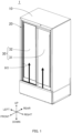
FIG. 1 is a perspective view of a cold storage according to an embodiment of the present disclosure; -
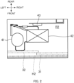
FIG. 2 is a horizontal sectional view illustrating a configuration inside a machine chamber; -
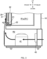
FIG. 3 is a partial vertical sectional view of the cold storage; -
FIG. 4 is a vertical sectional view illustrating a cooling region inside a cold storage chamber; -
FIG. 5 is a block diagram of the cold storage; -
FIG. 6 is a flowchart of a program executed by a control apparatus; -
FIG. 7 is a flowchart of a program executed by the control apparatus; -
FIG. 8 is a flowchart of a program executed by the control apparatus; and -
FIG. 9 is a time chart illustrating an operation of a drain pan. - An embodiment of a cold storage according to the present disclosure will be described below with reference to the drawings. In the following description, it is assumed that, as denoted by arrows in
FIG. 1 , a side where slidingdoor 30 is disposed is a front side with respect tocold storage 1, and a side opposite to the above side is a rear side with respect tocold storage 1. Left and right sides whencold storage 1 is viewed from the front are respectively left and right sides with respect tocold storage 1. A side away from a plane on whichcold storage 1 is installed is an upper side with respect tocold storage 1, and a side opposite to the above side is a lower side with respect tocold storage 1. -
Cold storage 1 is a pharmaceutical cold storage for storing pharmaceuticals at a low temperature.Cold storage 1 may be a cold storage for blood or a constant temperature container. As illustrated inFIGS. 1 to 4 ,cold storage 1 includesbox 10,frame 20, and slidingdoor 30. -
Box 10 has, in its front surface, opening H1 that provides an entrance opened and closed with movement of slidingdoor 30. A heat insulating material is filled between an outer surface and an inner surface ofbox 10. A space surrounded by the inner surface ofbox 10 serves as cold storage chamber R1, namely a space in which pharmaceuticals are stored (FIGS. 3 and4 ). -
Frame 20 is attached tobox 10 in such a way of bordering opening H1.Frame 20 includesouter rail 21 andinner rail 22 that are disposed on a bottom surface offrame 20 and that extend in a left-right direction.Inner rail 22 is positioned rearward of outer rail 21 (on a side nearer to cold storage chamber R1) (FIG. 3 ). In addition, slidingdoor 30 is attached toframe 20. - Sliding
door 30 includes first sliding door 31 and second sliding door 32. First slidingdoor 31 is attached to be movable alongouter rail 21. First slidingdoor 31 is positioned in a right-side region withinframe 20 in a closed state. Second slidingdoor 32 is attached to be movable alonginner rail 22. Second slidingdoor 32 is positioned in a left -side region withinframe 20 in a closed state. Opening H1 and hence cold storage chamber R1 are opened and closed with movements of first slidingdoor 31 and second slidingdoor 32. - Since first sliding
door 31 is disposed onouter rail 21 and second slidingdoor 32 is disposed oninner rail 22, second slidingdoor 32 is positioned on a side nearer to cold storage chamber R1 than first slidingdoor 31. Accordingly, an amount of dew condensation generated on second slidingdoor 32 is larger than that generated on first slidingdoor 31. -
Box 10 further includes machine chamber R2 under cold storage chamber R1 (FIGS. 2 and3 ). - Machine chamber R2 has air outlet H2. Air outlet H2 is formed to be opened in front of
frame 20 such that an airflow (described later) is blown to slidingdoor 30. -
Compressor 41 andcondenser 42, both constituting a refrigeration circuit for cooling the inside of cold storage chamber R1, andfan 43 are disposed in machine chamber R2.Compressor 41 is disposed in a left-side region within machine chamber R2. In other words,compressor 41 is disposed at a position nearer to second slidingdoor 32 in a state of closing cold storage chamber R1 than first slidingdoor 31 in a state of closing cold storage chamber R1.Condenser 42 is disposed in machine chamber R2 substantially at a center. -
Fan 43 generates an airflow. The airflow is denoted by thick arrows inFIGS. 1 and3 .Fan 43 is rotated to take outside air into machine chamber R2 and to generate the airflow. The airflow passes aroundcompressor 41 and condenser 42. Whencompressor 41 andcondenser 42 are in an operating state, the airflow passing aroundcompressor 41 andcondenser 42 is warmed by the temperature ofcompressor 41 and the temperature ofcondenser 42. - Furthermore, the airflow is blown out through air outlet H2 and is sprayed to sliding
door 30. Because the warmed airflow warms slidingdoor 30, generation of the dew condensation on slidingdoor 30 is suppressed. - As illustrated in
FIG. 4 , cold storage chamber R1 is partitioned bysidewall 51 into storage region R1a and cooling region R1b. Storage region R1a is a region where the pharmaceuticals and so on are stored. Cooling region R1b is a region where the air in cold storage chamber R1 is cooled. -
Second fan 52,evaporator 53 constituting the refrigeration circuit,sensor 54, defrostheater 55,second sensor 56,drain pan 57, anddrain pan heater 58 are disposed in an upper end portion of cold storage chamber R1 on the rear side. The surrounding ofevaporator 53 serves as cooling region R1b. Stated another way,second fan 52,evaporator 53 constituting the refrigeration circuit,sensor 54, defrostheater 55,second sensor 56,drain pan 57, anddrain pan heater 58 are disposed in cooling region R1b. -
Second fan 52 is rotated to take air in storage region R1a into cooling region R1b.Second fan 52 is disposed in an upper end zone of cooling region R1b. Accordingly,second fan 52 takes in air present in an upper zone of storage region R1a. The air having been taken into cooling region R1b is blown into storage region R1a through an opening that is formed at the bottom of cooling region R1b. Thus, as indicated by an arrow inFIG. 4 , the air having been taken into cooling region R1b flows downward from the upper end zone of cooling region R1b. -
Evaporator 53 cools the air having been taken into cooling region R1b.Evaporator 53 is disposed on a lower side thansecond fan 52.Evaporator 53 includespipe 53a through which a coolant circulating in the refrigeration circuit flows, andfin 53b attached to be held in contact withpipe 53a. -
Sensor 54 detects a temperature in cold storage chamber R1.Sensor 54 is disposed in cooling region R1b on an upper side thanevaporator 53. In other words,sensor 54 detects a temperature of the air taken into cooling region R1b before the taken-in air is cooled byevaporator 53. Thus, the temperature detected bysensor 54 is equal to the temperature in the air in storage region R1a. -
Defrost heater 55 serves as a heater for, when operated, melting frost adhering topipe 53a andfin 53b.Defrost heater 55 is, for example, a sheath heater or a cord heater.Defrost heater 55 is attached at a position away frompipe 53a ofevaporator 53 while it is held in contact withfin 53b. An operation started with activation ofdefrost heater 55 is especially referred to as a "defrost operation". The defrost operation is performed during a period in whichcompressor 41 is stopped. -
Second sensor 56 is disposed at a position away frompipe 53a while it is held in contact withfin 53b.Second sensor 56 detects a temperature offin 53b. -
Drain pan 57 receives water generated due to the defrost operation.Drain pan 57 is disposed underevaporator 53. The frost adhering topipe 53a andfin 53b is melted by the defrost operation, whereby water is generated. The generated water falls down ontodrain pan 57 and is drained to machine chamber R2 through a pipe (not illustrated). -
Drain pan heater 58 is a heater forheating drain pan 57.Drain pan heater 58 is, for example, a sheath heater or a cord heater. An amount of heat generated bydrain pan heater 58 is smaller than that generated bydefrost heater 55.Drain pan heater 58 is attached to be held in contact with a rear surface ofdrain pan 57. There is a possibility that the water received bydrain pan 57 may be frozen by being cooled byevaporator 53. Even when the water received bydrain pan 57 is frozen and an ice is generated, the ice can be melted with the operation ofdrain pan heater 58. -
Defrost heater 55 anddrain pan heater 58 are disposed in cooling region R1b as described above. In other words, defrostheater 55 anddrain pan heater 58 are disposed in cold storage chamber R1. - As illustrated in
FIG. 5 ,cold storage 1 further includesinputter 61 andcontrol apparatus 62.Inputter 61 is used to input a set temperature for cold storage chamber R1.Inputter 61 is, for example, a touch panel. -
Control apparatus 62 is a computer for supervising and controllingcold storage 1.Control apparatus 62 includes a storage apparatus for storing a computer program (hereinafter simply referred to as a "program") and a processor for executing the computer program. -
Inputter 61,sensor 54,second sensor 56,compressor 41, defrostheater 55,drain pan heater 58,fan 43, andsecond fan 52 are electrically connected to controlapparatus 62.Control apparatus 62 obtains the set temperature input throughinputter 61, the temperature detected bysensor 54, and the temperature detected bysecond sensor 56.Control apparatus 62controls compressor 41, defrostheater 55,drain pan heater 58,fan 43, andsecond fan 52 based on the set temperature, the temperature detected bysensor 54, and the temperature detected bysecond sensor 56. - With
control apparatus 62 executing the program,compressor 41 is controlled, and hence the temperature in cold storage chamber R1 is controlled to the set temperature. In more detail,control apparatus 62 repeats operation and stop ofcompressor 41 based on the set temperature and the temperature detected by sensor 54 (Fig. 9 ). When the program is executed,fan 43 andsecond fan 52 are controlled to rotate continuously. - The operation of
drain pan heater 58, realized withcontrol apparatus 62 executing the program, will be described below with reference to flowcharts ofFIGS. 6 to 8 . At the start time of the program,drain pan heater 58 is not operated. Furthermore, when the program is executed, the operation and the stop ofCompressor 41 are repeated. - In S10 illustrated in
FIG. 6 ,control apparatus 62 determines whether or not the set temperature obtained frominputter 61 is equal to or lower than a specified temperature. The specified temperature is given as, for example, 3°C, taking into consideration that the amount of the dew condensation generated on slidingdoor 30 increases relatively when the temperature in cold storage chamber R1 reaches the specified temperature. The specified temperature is previously set in the program executed bycontrol apparatus 62 in a manufacturing stage ofcold storage 1. If the set temperature is equal to or lower than the specified temperature (S10: YES),control apparatus 62 executes synchronous control (described later) inS 11. - On the other hand, if the set temperature is higher than the specified temperature (S10: NO),
control apparatus 62 executes asynchronous control (described later) in S12. - The case in which the synchronous control, illustrated in
FIG. 7 , is executed will be described below. In the synchronous control,drain pan heater 58 is operated whencompressor 41 is operated. - In S20,
control apparatus 62 determines whether or notcompressor 41 is in the operating state. Ifcompressor 41 is stopped (S20: NO),control apparatus 62 repeatedly executes S20. - On the other hand, if
compressor 41 is in the operating state (S20: YES),control apparatus 62 determines in S21 whether or not the temperature detected bysensor 54 is equal to or lower than a temperature (hereinafter referred to as a "sum temperature") resulting from adding a specified value to the set temperature. The specified value is a value at which, regardless of the set temperature being any temperature, the amount of the dew condensation generated on slidingdoor 30 decreases relatively when the temperature in cold storage chamber R1 reaches the sum temperature. The specified value is a constant value irrespective of the set temperature and is previously set in the program executed bycontrol apparatus 62 in the manufacturing stage ofcold storage 1. The specified value is, for example, 5. - If the temperature in cold storage chamber R1 is relatively higher than the set temperature and hence the temperature detected by
sensor 54 is higher than the sum temperature (S21: NO),control apparatus 62 returns the program to S20 without operatingdrain pan heater 58. - On the other hand, if, because of
compressor 41 being in the operating state, the temperature in cold storage chamber R1 drops and the temperature detected bysensor 54 becomes equal to or lower than the sum temperature (S21: YES),control apparatus 62 operatesdrain pan heater 58 in S22. - Then,
control apparatus 62 determines in S23 whether or notcompressor 41 is stopped. If the temperature in cold storage chamber R1 does not reach the set temperature and hencecompressor 41 remains in the operating state (S23: NO),control apparatus 62 repeatedly executes S23. - On the other hand, if the temperature in cold storage chamber R1 reaches the set temperature and hence
compressor 41 is stopped (S23: YES),control apparatus 62 stops drainpan heater 58 in S24 and returns the program to S20. - The case in which the asynchronous control, illustrated in
FIG. 8 , is executed will be described below. In the asynchronous control, the operation ofcompressor 41 and the operation ofdrain pan heater 58 are not in synchronism with each other. - In S30,
control apparatus 62 determines whether or not the operating state ofcompressor 41 is stopped. If the operating state ofcompressor 41 is continued (S30: NO),control apparatus 62 repeatedly executes S30. - On the other hand, if the temperature in
cold storage 1 reaches the set temperature and hence the operation ofcompressor 41 is stopped (S30: YES),control apparatus 62 operatesdrain pan heater 58 and starts the defrost operation, more specifically, the operation ofdefrost heater 55 in S31. The defrost operation is continued until the temperature detected bysecond sensor 56 reaches a second specified temperature. - Then,
control apparatus 62 determines in S32 whether or not the temperature detected bysecond sensor 56 is equal to or higher than a third specified temperature. The third specified temperature is a threshold set to stop the operation ofdrain pan heater 58. The third specified temperature is higher than the second specified temperature. The second specified temperature and the third specified temperature are previously set in the program executed bycontrol apparatus 62 in the manufacturing stage ofcold storage 1. - If the temperature detected by
second sensor 56 is lower than the third specified temperature (S32: NO),control apparatus 62 repeatedly executes S32. - If the temperature detected by
second sensor 56 becomes equal to or higher than the third specified temperature (S32: YES),control apparatus 62 stops drainpan heater 58 in S33 and returns the program to S30. - The temperature in cold storage chamber R1 when the temperature detected by
second sensor 56 becomes the third specified temperature is at a level that is sufficiently lower than a temperature at which there is a possibility of adversely affecting the pharmaceuticals and so on stored in cold storage chamber R1. - The operation of
cold storage 1 when the synchronous control ofdrain pan heater 58 is performed will be described below with reference to a time chart ofFIG. 9 . When the program is executed,fan 43 is continuously rotated, and hence the airflow is blown to slidingdoor 30 as described above. - If the set temperature is equal to or lower than the specified temperature (S10: YES) and if the temperature detected by
sensor 54 is equal to or lower than the sum temperature (S21: YES) at the time whencompressor 41 starts the operation (S20: YES) (time 11),drain pan heater 58 is operated (S22). - Because
compressor 41 is operated, the air in cold storage chamber R1 is cooled byevaporator 53. On the other hand, becausedrain pan heater 58 is disposed in cold storage chamber R1,drain pan heater 58 heats the air cooled byevaporator 53. Thus,drain pan heater 58 works to suppress the cooling performed by the refrigeration circuit. Accordingly, whendrain pan heater 58 is operated, a time taken for the temperature in cold storage chamber R1 to reach the set temperature is longer than that whendrain pan heater 58 is not operated. In other words, an operating time ofcompressor 41 whendrain pan heater 58 is operated is longer than that whendrain pan heater 58 is stopped. - As the operating time of
compressor 41 increases, the temperature ofcompressor 41 rises. Due to the rise of the compressor temperature, the temperature of the airflow passing aroundcompressor 41 also rises. In other words, the temperature of the airflow whendrain pan heater 58 is operated becomes higher than that whendrain pan heater 58 is stopped. Thus, when the set temperature is set to be equal to or lower than the specified temperature at which the amount of the dew condensation generated on slidingdoor 30 increases relatively, the temperature of the airflow can be raised, and hence the generation of the dew condensation can be suppressed. - As described above,
compressor 41 is disposed nearer to second slidingdoor 32 in the state of closing cold storage chamber R1 than to first slidingdoor 31 in the state of closing cold storage chamber R1. Accordingly, the temperature of the airflow blown to second slidingdoor 32 can be made higher than that blown to first slidingdoor 31. Moreover, as described above, the amount of the dew condensation generated on second slidingdoor 32 is larger than that generated on first slidingdoor 31. In other words, the amount of the dew condensation generated on second slidingdoor 32 can be effectively suppressed depending on the layout position ofcompressor 41. - When
compressor 41 is stopped upon the temperature in cold storage chamber R1 dropping and reaching the set temperature (S23: YES, time t2),drain pan heater 58 is stopped (S24). - Then, if the set temperature is equal to or lower than the specified temperature (S10: YES) and if the temperature detected by
sensor 54 is higher than the sum temperature (S21: NO) even at the time whencompressor 41 starts the operation (S20: YES) (time t4),drain pan heater 58 is not operated. When the temperature detected bysensor 54 is higher than the sum temperature, the difference between the temperature in cold storage chamber R1 and the set temperature is relatively large. Therefore,drain pan heater 58 is controlled to be not operated with higher priority given to the cooling by the refrigeration circuit. - The case in which the temperature detected by
sensor 54 is higher than the sum temperature corresponds to, for example, the case in which the outside air flows into cold storage chamber R1 because of slidingdoor 30 being opened by a user and the temperature in cold storage chamber R1 rises. Moreover, when the temperature detected bysensor 54 is higher than the sum temperature, the amount of the dew condensation generated on slidingdoor 30 is relatively small as described above. Accordingly, the generation of the dew condensation can be sufficiently suppressed with the airflow even at the temperature whendrain pan heater 58 is not operated. - Then, when the temperature in cold storage chamber R1 drops due to the operation of
compressor 41 and the temperature detected bysensor 54 becomes equal to or lower than the sum temperature (S21: YES),drain pan heater 58 is operated (S22, time t5). Moreover, whencompressor 41 is stopped upon the temperature in cold storage chamber R1 further dropping and reaching the set temperature (S23: YES, time t6),drain pan heater 58 is stopped (S24). - The operation of
cold storage 1 when the asynchronous control ofdrain pan heater 58 is performed will be described below with reference to the time chart ofFIG. 9 . When the asynchronous control is performed,fan 43 is continuously rotated, and the airflow is blown to slidingdoor 30 as in the above-described case. - In the state of the set temperature being higher than the specified temperature (S10: NO), at the time when
compressor 41 starts the operation (S30: NO) (time t1),drain pan heater 58 is not operated. Accordingly, the temperature of the airflow blown to slidingdoor 30 becomes lower than that whendrain pan heater 58 is operated. However, when the set temperature is higher than the specified temperature, the amount of the dew condensation generated on slidingdoor 30 is smaller than that generated on slidingdoor 30 when the set temperature is equal to or lower than the specified temperature. As a result, the dew condensation generated on slidingdoor 30 can be sufficiently suppressed. - When the operation of
compressor 41 is stopped upon the temperature in cold storage chamber R1 dropping and reaching the set temperature (S30: YES, time t2),drain pan heater 58 is operated (S31). At that time (t2), defrostheater 55 is also operated. - Because
compressor 41 is stopped, the temperature ofcompressor 41 does not rise in spite ofdrain pan heater 58 being operated. Accordingly, the temperature of the airflow does not rise. - When the temperature detected by
second sensor 56 becomes equal to or higher than the third specified temperature due to melting of the frost adhering tofin 53b and rising of the temperature offin 53b (S32: YES, time t3), the operation ofdrain pan heater 58 is stopped (S33). - Then,
drain pan heater 58 repeatedly executes processes of starting the operation when the operation ofcompressor 41 is stopped (time t6) and stopping the operation when the temperature detected bysecond sensor 56 becomes equal to or higher than the third specified temperature (t7). - The present disclosure is not limited to the above-described embodiment. Modifications obtained by variously modifying the embodiment also fall within the scope of the present disclosure insofar as the modifications do not depart from the gist of the present disclosure.
- For example, in the synchronous control, when
compressor 41 is in the operating state,drain pan heater 58 may be operated irrespective of the sum temperature. In that case, S21 in the flowchart illustrated inFIG. 7 is not executed. Stated another way,control apparatus 62 operatesdrain pan heater 58 when a condition of the set temperature in cold storage chamber R1 being equal to or lower than the specified temperature and a condition ofcompressor 41 being in the operating state are satisfied. - Furthermore,
compressor 41 may be disposed at the center of machine chamber R2 or at a position nearer to first slidingdoor 31 in the state of closing cold storage chamber R1 than second slidingdoor 32 in the state of closing cold storage chamber R1. - Moreover, in the synchronous control, defrost
heater 55 may be operated instead ofdrain pan heater 58 whencompressor 41 is in the operating state. - The disclosure of
Japanese Patent Application No. 2021-043838 filed on March 17, 2021 - The present disclosure can be widely applied to cold storages, such as a cold storage for pharmaceuticals, a cold storage for blood, and a constant temperature container.
-
- 1 cold storage
- 10 box
- 20 frame
- 30 sliding door
- 41 compressor
- 42 condenser
- 43 fan
- 52 second fan
- 54 sensor
- 56 second sensor
- 57 drain pan
- 58 drain pan heater
- H1 opening
- H2 air outlet
- R1 cold storage chamber
- R2 machine chamber
Claims (4)
- A cold storage comprising:a box including a cold storage chamber, a sliding door that opens and closes the cold storage chamber, and a machine chamber;a compressor disposed in the machine chamber and constituting a refrigeration circuit that cools an inside of the cold storage chamber;a fan that generates an airflow passing around the compressor and blown to the sliding door through an air outlet opened to the machine chamber;a heater disposed in the cold storage chamber; anda control apparatus that operates the heater when a condition of a set temperature for the cold storage chamber being equal to or lower than a specified temperature and a condition of the compressor being in an operating state are satisfied.
- A cold storage comprising:a box including a cold storage chamber, a sliding door that opens and closes the cold storage chamber, and a machine chamber;a compressor disposed in the machine chamber and constituting a refrigeration circuit that cools an inside of the cold storage chamber;a fan that generates an airflow passing around the compressor and blown to the sliding door through an air outlet opened to the machine chamber;a heater disposed in the cold storage chamber;a sensor that detects a temperature in the cold storage chamber; anda control apparatus that operates the heater when a condition of a set temperature for the cold storage chamber being equal to or lower than a specified temperature, a condition of the compressor being in an operating state, and a temperature detected by the sensor being equal to or lower than a temperature resulting from adding a specified value to the set temperature are satisfied.
- The cold storage according to Claim 1 or 2,wherein the sliding door includes a first sliding door that opens and closes the cold storage chamber, and a second sliding door that opens and closes the cold storage chamber at a position between the cold storage chamber and the first sliding door, andthe compressor is disposed at a position nearer to the second sliding door in a state of closing the cold storage chamber than the first sliding door in a state of closing the cold storage chamber.
- The cold storage according to any one of Claims 1 to 3, further comprising a drain pan that receives water generated due to a defrost operation,
wherein the heater is a drain pan heater that heats the drain pan.
Applications Claiming Priority (2)
| Application Number | Priority Date | Filing Date | Title |
|---|---|---|---|
| JP2021043838 | 2021-03-17 | ||
| PCT/JP2022/004485 WO2022196170A1 (en) | 2021-03-17 | 2022-02-04 | Cold storage unit |
Publications (2)
| Publication Number | Publication Date |
|---|---|
| EP4269917A1 true EP4269917A1 (en) | 2023-11-01 |
| EP4269917A4 EP4269917A4 (en) | 2024-05-29 |
Family
ID=83322227
Family Applications (1)
| Application Number | Title | Priority Date | Filing Date |
|---|---|---|---|
| EP22770930.0A Pending EP4269917A4 (en) | 2021-03-17 | 2022-02-04 | COLD STORAGE UNIT |
Country Status (5)
| Country | Link |
|---|---|
| US (1) | US12416441B2 (en) |
| EP (1) | EP4269917A4 (en) |
| JP (1) | JP7478307B2 (en) |
| CN (1) | CN116868018A (en) |
| WO (1) | WO2022196170A1 (en) |
Family Cites Families (15)
| Publication number | Priority date | Publication date | Assignee | Title |
|---|---|---|---|---|
| JPH0693856B2 (en) * | 1989-04-19 | 1994-11-24 | 三洋電機株式会社 | Showcase |
| US4977754A (en) * | 1990-05-01 | 1990-12-18 | Specialty Equipment Companies, Inc. | Next-to-be-purchased cold beverage merchandiser |
| JPH06159904A (en) * | 1992-11-27 | 1994-06-07 | Sanyo Electric Co Ltd | Low temperature showcase |
| JP3190793B2 (en) * | 1994-09-08 | 2001-07-23 | ホシザキ電機株式会社 | Temperature control device for cooling storage |
| JP2000088438A (en) | 1998-09-09 | 2000-03-31 | Sanyo Electric Co Ltd | Cooling storage cabinet |
| JP2000329445A (en) * | 1999-05-20 | 2000-11-30 | Hoshizaki Electric Co Ltd | Low temperature storage chamber |
| JP4229555B2 (en) * | 1999-12-17 | 2009-02-25 | 福島工業株式会社 | Storage room with temperature control function |
| JP4036597B2 (en) * | 2000-03-08 | 2008-01-23 | 三洋電機株式会社 | Low temperature showcase |
| JP2005164199A (en) * | 2003-12-05 | 2005-06-23 | Matsushita Electric Ind Co Ltd | refrigerator |
| EP1878986A1 (en) * | 2005-04-27 | 2008-01-16 | Fukushima Kogyo Co., Ltd. | Refrigerator |
| JP5713536B2 (en) * | 2009-01-05 | 2015-05-07 | 三菱電機株式会社 | Heat pump water heater |
| JP2017020745A (en) | 2015-07-14 | 2017-01-26 | ホシザキ株式会社 | Cooling storage |
| CN209926609U (en) * | 2018-12-21 | 2020-01-10 | 青岛经济技术开发区海尔热水器有限公司 | A water receiving tray deicing device and a heat pump water heater using the same |
| CN114270120B (en) | 2019-08-28 | 2023-08-18 | 普和希株式会社 | Cooler |
| JP2021043838A (en) | 2019-09-13 | 2021-03-18 | パイオニア株式会社 | Information processing equipment, control methods, programs and storage media |
-
2022
- 2022-02-04 EP EP22770930.0A patent/EP4269917A4/en active Pending
- 2022-02-04 JP JP2023506851A patent/JP7478307B2/en active Active
- 2022-02-04 CN CN202280015897.8A patent/CN116868018A/en active Pending
- 2022-02-04 WO PCT/JP2022/004485 patent/WO2022196170A1/en not_active Ceased
-
2023
- 2023-08-04 US US18/365,733 patent/US12416441B2/en active Active
Also Published As
| Publication number | Publication date |
|---|---|
| EP4269917A4 (en) | 2024-05-29 |
| JPWO2022196170A1 (en) | 2022-09-22 |
| US12416441B2 (en) | 2025-09-16 |
| JP7478307B2 (en) | 2024-05-02 |
| CN116868018A (en) | 2023-10-10 |
| US20240019192A1 (en) | 2024-01-18 |
| WO2022196170A1 (en) | 2022-09-22 |
Similar Documents
| Publication | Publication Date | Title |
|---|---|---|
| EP2426450A2 (en) | Direct cooling refrigerator and control method thereof | |
| JP5722057B2 (en) | Cooling storage | |
| JP6765715B2 (en) | refrigerator | |
| JP2016223752A (en) | refrigerator | |
| US7665320B2 (en) | Damper assembly and methods for a refrigeration device | |
| JP2012092986A (en) | Refrigerator | |
| US12416441B2 (en) | Cold storage | |
| JP7536468B2 (en) | Cooling cabinet | |
| EP4269914A1 (en) | Cold storage | |
| US10161666B2 (en) | Cool air path damper assembly with elastic anti-freezing member | |
| JP2018031552A (en) | Refrigerator-freezer | |
| JP6657032B2 (en) | Cooling storage | |
| JP2015206472A (en) | refrigerator | |
| JP6212709B2 (en) | refrigerator | |
| JP7391515B2 (en) | refrigerator | |
| JP6695199B2 (en) | Refrigerated storage | |
| KR20070016319A (en) | Vegetable room independent temperature control system of refrigerator | |
| JP7158309B2 (en) | refrigerator | |
| JPWO2017017850A1 (en) | Freezer refrigerator | |
| JP6165668B2 (en) | refrigerator | |
| JP6165667B2 (en) | refrigerator | |
| US20250305726A1 (en) | Refrigeration apparatus | |
| US20230392848A1 (en) | Refrigerator and control method thereof | |
| JP2023132053A (en) | cooling storage | |
| JP2023132052A (en) | cooling storage |
Legal Events
| Date | Code | Title | Description |
|---|---|---|---|
| STAA | Information on the status of an ep patent application or granted ep patent |
Free format text: STATUS: THE INTERNATIONAL PUBLICATION HAS BEEN MADE |
|
| PUAI | Public reference made under article 153(3) epc to a published international application that has entered the european phase |
Free format text: ORIGINAL CODE: 0009012 |
|
| STAA | Information on the status of an ep patent application or granted ep patent |
Free format text: STATUS: REQUEST FOR EXAMINATION WAS MADE |
|
| 17P | Request for examination filed |
Effective date: 20230725 |
|
| AK | Designated contracting states |
Kind code of ref document: A1 Designated state(s): AL AT BE BG CH CY CZ DE DK EE ES FI FR GB GR HR HU IE IS IT LI LT LU LV MC MK MT NL NO PL PT RO RS SE SI SK SM TR |
|
| A4 | Supplementary search report drawn up and despatched |
Effective date: 20240430 |
|
| RIC1 | Information provided on ipc code assigned before grant |
Ipc: A47F 3/04 20060101ALI20240424BHEP Ipc: F25D 21/14 20060101ALI20240424BHEP Ipc: F25D 21/08 20060101ALI20240424BHEP Ipc: F25D 21/04 20060101AFI20240424BHEP |
|
| DAV | Request for validation of the european patent (deleted) | ||
| DAX | Request for extension of the european patent (deleted) | ||
| STAA | Information on the status of an ep patent application or granted ep patent |
Free format text: STATUS: EXAMINATION IS IN PROGRESS |
|
| RAP3 | Party data changed (applicant data changed or rights of an application transferred) |
Owner name: PHC HOLDINGS CORPORATION |
|
| 17Q | First examination report despatched |
Effective date: 20250113 |
|
| GRAP | Despatch of communication of intention to grant a patent |
Free format text: ORIGINAL CODE: EPIDOSNIGR1 |
|
| STAA | Information on the status of an ep patent application or granted ep patent |
Free format text: STATUS: GRANT OF PATENT IS INTENDED |
|
| INTG | Intention to grant announced |
Effective date: 20251201 |
|
| GRAJ | Information related to disapproval of communication of intention to grant by the applicant or resumption of examination proceedings by the epo deleted |
Free format text: ORIGINAL CODE: EPIDOSDIGR1 |
|
| STAA | Information on the status of an ep patent application or granted ep patent |
Free format text: STATUS: EXAMINATION IS IN PROGRESS |
|
| INTC | Intention to grant announced (deleted) |