EP4269848A1 - Relief valve with check function - Google Patents
Relief valve with check function Download PDFInfo
- Publication number
- EP4269848A1 EP4269848A1 EP21914985.3A EP21914985A EP4269848A1 EP 4269848 A1 EP4269848 A1 EP 4269848A1 EP 21914985 A EP21914985 A EP 21914985A EP 4269848 A1 EP4269848 A1 EP 4269848A1
- Authority
- EP
- European Patent Office
- Prior art keywords
- valve body
- port
- check
- relief
- relief valve
- Prior art date
- Legal status (The legal status is an assumption and is not a legal conclusion. Google has not performed a legal analysis and makes no representation as to the accuracy of the status listed.)
- Withdrawn
Links
Images



Classifications
-
- F—MECHANICAL ENGINEERING; LIGHTING; HEATING; WEAPONS; BLASTING
- F16—ENGINEERING ELEMENTS AND UNITS; GENERAL MEASURES FOR PRODUCING AND MAINTAINING EFFECTIVE FUNCTIONING OF MACHINES OR INSTALLATIONS; THERMAL INSULATION IN GENERAL
- F16K—VALVES; TAPS; COCKS; ACTUATING-FLOATS; DEVICES FOR VENTING OR AERATING
- F16K17/00—Safety valves; Equalising valves, e.g. pressure relief valves
- F16K17/18—Safety valves; Equalising valves, e.g. pressure relief valves opening on surplus pressure on either side
- F16K17/19—Equalising valves predominantly for tanks
- F16K17/196—Equalising valves predominantly for tanks spring-loaded
-
- F—MECHANICAL ENGINEERING; LIGHTING; HEATING; WEAPONS; BLASTING
- F16—ENGINEERING ELEMENTS AND UNITS; GENERAL MEASURES FOR PRODUCING AND MAINTAINING EFFECTIVE FUNCTIONING OF MACHINES OR INSTALLATIONS; THERMAL INSULATION IN GENERAL
- F16K—VALVES; TAPS; COCKS; ACTUATING-FLOATS; DEVICES FOR VENTING OR AERATING
- F16K17/00—Safety valves; Equalising valves, e.g. pressure relief valves
- F16K17/02—Safety valves; Equalising valves, e.g. pressure relief valves opening on surplus pressure on one side; closing on insufficient pressure on one side
- F16K17/04—Safety valves; Equalising valves, e.g. pressure relief valves opening on surplus pressure on one side; closing on insufficient pressure on one side spring-loaded
- F16K17/06—Safety valves; Equalising valves, e.g. pressure relief valves opening on surplus pressure on one side; closing on insufficient pressure on one side spring-loaded with special arrangements for adjusting the opening pressure
-
- F—MECHANICAL ENGINEERING; LIGHTING; HEATING; WEAPONS; BLASTING
- F16—ENGINEERING ELEMENTS AND UNITS; GENERAL MEASURES FOR PRODUCING AND MAINTAINING EFFECTIVE FUNCTIONING OF MACHINES OR INSTALLATIONS; THERMAL INSULATION IN GENERAL
- F16K—VALVES; TAPS; COCKS; ACTUATING-FLOATS; DEVICES FOR VENTING OR AERATING
- F16K47/00—Means in valves for absorbing fluid energy
- F16K47/01—Damping of valve members
- F16K47/011—Damping of valve members by means of a dashpot
- F16K47/0112—Damping of valve members by means of a dashpot the valve members comprising a dashpot sliding over a fixed plunger
-
- F—MECHANICAL ENGINEERING; LIGHTING; HEATING; WEAPONS; BLASTING
- F16—ENGINEERING ELEMENTS AND UNITS; GENERAL MEASURES FOR PRODUCING AND MAINTAINING EFFECTIVE FUNCTIONING OF MACHINES OR INSTALLATIONS; THERMAL INSULATION IN GENERAL
- F16K—VALVES; TAPS; COCKS; ACTUATING-FLOATS; DEVICES FOR VENTING OR AERATING
- F16K17/00—Safety valves; Equalising valves, e.g. pressure relief valves
- F16K17/02—Safety valves; Equalising valves, e.g. pressure relief valves opening on surplus pressure on one side; closing on insufficient pressure on one side
- F16K17/04—Safety valves; Equalising valves, e.g. pressure relief valves opening on surplus pressure on one side; closing on insufficient pressure on one side spring-loaded
Definitions
- the present invention relates to a relief valve with a check function that relieves hydraulic fluid from a first port to a second port.
- a relief valve with a check function relieves hydraulic oil from a first port to a second port when the pressure of the first port becomes higher than a preset pressure (relief function). Also, the relief valve with a check function is capable of supplying the hydraulic oil from the second port to the first port when the pressure of the second port becomes higher than the pressure of the first port (check function).
- a relief valve with a check function for example, a relief valve with a check function of PTL 1 is known.
- the relief valve with a check function of PTL 1 has a first valve body having a check function, and a second valve body having a relief function.
- the second valve body is inserted through the first valve body. And, when the first valve body operates, the first valve body and the second valve body integrally move. As described above, since the first valve body and the second valve body are integrally configured, a mechanism that adjusts the relief pressure from outside is not provided.
- a relief valve with a check function of the present invention is a relief valve with a check function that relieves hydraulic fluid from a first port to a second port, the relief valve with a check function including: a housing having a body, and an adjustment member provided to be capable of advancing and retracting with respect to the body; a seat member provided in the body, the seat member being formed with a relief passage connecting to each of the first port and the second port; a relief valve body that is unseated from or seated on the seat member to open or close the relief passage, the relief valve body receiving pressure of the first port in a direction of opening the relief passage; a first biasing member that biases the relief valve body against the pressure of the first port, with a biasing force being adjusted by advance or retraction of the adjustment member; a check valve body that opens or closes a check passage connecting to each of the first port and the second port, the check valve body receiving pressure of the second port in a direction of opening the check passage; and a second biasing member that biases the check valve body
- the present invention it is possible to adjust the biasing force of the first biasing member by advancing or retracting the adjustment member with respect to the body.
- the relief pressure from outside.
- a hydraulic circuit includes a relief valve 1 as shown in Fig. 1 .
- the relief valve 1 As the pressure of hydraulic fluid of a first port 2 exceeds a predetermined pressure (namely, relief pressure), the relief valve 1 flows the hydraulic fluid from the first port 2 to a second port 3. Also, when the pressure of the hydraulic fluid of the first port 2 is lower than the pressure of the second port 3, the relief valve 1 flows the hydraulic fluid from the second port 3 to the first port 2.
- the first port 2 is, for example, an actuator port
- the second port 3 is a tank port.
- the relief valve 1 includes a valve block 11, a housing 12, a seat member 13, a relief valve body 14, a first biasing member 15, a check valve body 16, and a second biasing member 17.
- the valve block 11 is a block body to which the housing 12 is to be attached. More specifically, the valve block 11 has a valve hole 11a, a first passage 11b, and a second passage 11c.
- the valve hole 11a is a bottomed hole formed along an axial line L1. In the bottom surface that defines the valve hole 11a, the first port 2 is formed.
- the first passage 11b connects to the valve hole 11a via the first port 2.
- the second port 3 is formed in the inner peripheral surface that defines the valve hole 11a.
- the second passage 11c connects to the valve hole 11a via the second port 3.
- the housing 12 accommodates therein the seat member 13, the relief valve body 14, the first biasing member 15, the check valve body 16, and the second biasing member 17. Also, the housing 12 has a body 21, an adjustment plug 22, and a locknut 23. More specifically, the housing 12 is formed to have, for example, a topped cylindrical shape. Then, the housing 12 is inserted through the valve hole 11a with an opening 12a being directed to the first port 2. Therefore, the interior of the housing 12 connects to the first port 2 via the opening 12a of the housing 12.
- the body 21 is inserted through the valve hole 11a with one end part which is an end part of one side in the axial direction being directed to the first port 2. More specifically, the body 21 is formed to have a cylindrical shape. And, the body 21 is screwed with the valve block 11. Also, the inner hole of the body 21 has an opening hole 21a and an inner space 21b. The opening hole 21a is formed in the one end part that is an end part of one side in the axial direction of the body 21. Also, the opening hole 21a is formed to have a smaller diameter than the inner space 21b. And, in the body 21, a check valve seat 21c is formed to surround the opening hole 21a.
- a step part 21e is formed in a middle portion in the axial direction, and the inner space 21b is formed to have a small diameter on one side in the axial direction from the step part 21e compared with the other side in the axial direction.
- a plurality of communication passages 21d are formed in a portion of one side in the axial direction. The plurality of communication passages 21d radially penetrate the body 21. And, the plurality of communication passages 21d form a check passage 24 together with the opening hole 21a and the inner space 21b. That is, the check passage 24 is a passage that runs from the plurality of communication passages 21da to the opening hole 21a through the inner space 21b.
- the one end part of the body 21 is formed to have a tapered shape that is tapered toward one side in the axial direction in the present embodiment.
- the body 21 is inserted into the valve hole 11a such that the one end part seals the periphery of the first port 2, and is screwed with the valve block 11.
- the opening hole 21a is located opposite to the first port 2, and the plurality of communication passages 21d are located at positions corresponding to the second port 3. Therefore, the opening hole 21a connects to the first port 2, and the plurality of communication passages 21d connect to the second port 3.
- the adjustment plug 22 which is one example of an adjustment member is provided to be capable of advancing and retracting with respect to the body 21. More specifically, the adjustment plug 22 is formed to have a topped cylindrical shape. An opening side portion of the adjustment plug 22 is screwed in the body 21. That is, the adjustment plug 22 advances and retracts axially with respect to the body 21 by being rotated about the axial line (coincident with the axial line L1 in the present embodiment). In the present embodiment, the adjustment plug 22 is configured to be rotatable with the use of a jig such as a spanner, a hexagon wrench, and a screw driver.
- a jig such as a spanner, a hexagon wrench, and a screw driver.
- the locknut 23 restricts advance and retraction of the adjustment plug 22 with respect to the body 21. More specifically, the locknut 23 is formed to have an annular shape. And, the locknut 23 is screwed with a middle portion of the adjustment plug 22. The locknut 23 is fastened to come into contact with an other end part that is an end part of the other side in the axial direction of the body 21. As a result, advance and retraction in the axial direction of the adjustment plug 22 with respect to the body 21 is restricted. On the other hand, the locknut 23 is loosened to leave the other end part of the body 21. Thus, advance and retraction in the axial direction of the adjustment plug 22 with respect to the body 21 is allowed.
- the seat member 13 is provided inside the housing 12. Also, in the seat member 13, a relief passage 25 is formed. The relief passage 25 connects to each of the first port 2 and the second port 3. More specifically, the seat member 13 is formed to have a cylindrical shape. Still more specifically, a middle portion of the seat member 13 is formed to have a larger diameter than a one-end side portion in the axial direction, and have a smaller diameter than an other end side portion in the axial direction. Also, in an inner hole 13a of the seat member 13, a portion of one side in the axial direction forms a passage portion 13b, and a portion of the other side in the axial direction forms a valve insertion portion 13c. The passage portion 13b is formed to have a smaller diameter than the valve insertion portion 13c.
- a relief valve seat 13e is formed around the portion where the passage portion 13b opens to the valve insertion portion 13c. Also, in the middle portion of the seat member 13, a plurality of through passages 13f are formed. The plurality of through passages 13f form the relief passage 25 in the seat member 13 together with the inner hole 13a. That is, the relief passage 25 is a passage that runs from the passage portion 13b to the plurality of through passages 13f through the valve insertion portion 13c. Further, in the outer peripheral surface of the one-end side portion in the axial direction of the seat member 13, a plurality of communication holes 13g are formed. The plurality of communication holes 13g radially penetrate the one-end side portion in the axial direction of the seat member 13.
- a plurality of communication passages 13h are formed around the inner hole 13a.
- the communication passages 13h form a large-diameter portion of the seat member 13 parallel with the axial line L1. Also, the communication passages 13h form a restrictor.
- the seat member 13 configured as described above is located in a middle portion of the housing 12. More specifically, the seat member 13 is located on one side in the axial direction from the adjustment plug 22 inside the body 21. And, the seat member 13 is fixed inside the housing 12 by making the large-diameter portion be screwed with the inner peripheral surface of the body 21, and engaged with the step part 21e. Accordingly, the interior of the housing 12 is partitioned by the seat member 13 into a valve space 12b on one side in the axial direction and a first spring accommodating space 12c on the other side in the axial direction. Also, the seat member 13 is located such that the opening of one side in the axial direction is directed to the first port 2.
- an annular space 12d is formed between the middle portion of seat member 13 and the body 21, in the valve space 12b.
- the through passages 13f connect to the second port 3 via the annular space 12d. Since the opening of one side in the axial direction is directed to the first port 2, the passage portion 13b of the relief passage 25 connects to the first port 2. And, the communication passages 13h connect the valve space 12b and the first spring accommodating space 12c.
- the relief valve body 14 can be unseated from or seated on the seat member 13. Also, by unseating from or seating on the seat member 13, the relief passage 25 opens or closes. Further, the relief valve body 14 receives the pressure of the first port 2 in the direction of opening the relief passage 25 (hereinafter, referred to as "first opening direction"). More specifically, the relief valve body 14 is inserted through the valve insertion portion 13c. The relief valve body 14 is seated on the relief valve seat 13e by a distal end side portion 14a located on one side in the axial direction. Also, the relief valve body 14 is capable of sliding in the axial direction. Therefore, the relief valve body 14 is unseated from or seated on the relief valve seat 13e to open or close the relief passage 25. Also, the relief valve body 14 is configured as follows in the present embodiment.
- the relief valve body 14 is a direct-acting valve body formed of a solid member, and is formed to have a cylindrical shape. And, a middle portion of the relief valve body 14 is slidably supported by the seat member 13. Also, in the relief valve body 14, the distal end side portion 14a located on one side in the axial direction is formed to have a smaller diameter than the middle portion. The distal end side portion 14a of the relief valve body 14 is formed to have an acuminate shape. And, the distal end side portion 14a of the relief valve body 14 is seated on the relief valve seat 13e in such a manner that it sticks into the passage portion 13b. Therefore, the distal end side portion 14a of the relief valve body 14 forms a pressure receiving part 14c.
- the relief valve body 14 receives the hydraulic pressure of the passage portion 13b by the pressure receiving part 14c. More specifically, the relief valve body 14 receives the hydraulic pressure of the passage portion 13b in the portion corresponding to the passage portion 13b (see a first pressure receiving area A1 of the pressure receiving part 14c in Fig. 1 ). Since the hydraulic fluid of the first port 2 is guided to the passage portion 13b, the relief valve body 14 receives the hydraulic pressure of the first port 2 in the pressure receiving part 14c of the distal end side portion 14a. The relief valve body 14 receives from the hydraulic fluid the load that is the product of the first pressure receiving area A1 of the pressure receiving part 14c multiplied by the pressure of the first port 2 in the first opening direction.
- the relief valve body 14 is unseated from or seated on the seat member 13 in accordance with the pressure of the first port 2. Also, the relief valve body 14 has a spring bearing part 14b on the outer peripheral surface of a proximal end side portion located on the other side in the axial direction.
- the first biasing member 15 biases the relief valve body 14 in the direction of closing the relief passage 25 (hereinafter, referred to as "first closing direction") against the pressure of the first port 2. More specifically, the first biasing member 15 is a spring member. In the present embodiment, the first biasing member 15 is a compression coil spring. The first biasing member 15 is accommodated in the first spring accommodating space 12c of the housing 12 (namely, inside the adjustment plug 22) in a compressed state. More specifically, the first biasing member 15 comes into contact with the spring bearing part 14b of the relief valve body 14 at one end part, and comes into contact with the ceiling surface of the adjustment plug 22 at the other end part. Thus, the first biasing member 15 biases the relief valve body 14 in the first closing direction (namely, one side in the axial direction) against the pressure of the first port 2.
- the biasing force is adjusted by advancing or retracting the adjustment plug 22. More specifically, by loosening the locknut 23 and rotating the adjustment plug 22, it is possible to advance or retract the adjustment plug 22. As a result, the compression amount of the first biasing member 15 is adjusted. The biasing force of the first biasing member 15 is adjusted by the compression amount of the first biasing member 15.
- the check valve body 16 opens or closes the check passage 24. Also, the check valve body 16 receives the pressure of the second port 3 in the direction of opening the check passage 24 (hereinafter, referred to as "second opening direction"). Still more specifically, the check valve body 16 is accommodated in the housing 12, more specifically in the body 21. And, the check valve body 16 is slidably supported by the seat member 13. More specifically, the check valve body 16 is slidably attached outside the seat member 13. And, the check valve body 16 is unseated from or seated on the check valve seat 21c by sliding. The check valve body 16 is seated on the check valve seat 21c to close the check passage 24. Also, the check valve body 16 has a communication passage 16a. The communication passage 16a guides the hydraulic fluid flowing from the first port 2 to the relief passage 25 of the seat member 13 in the condition that the check valve body 16 closes the check passage 24. In the present embodiment, the check valve body 16 is formed in the following manner.
- the check valve body 16 is formed to have a cylindrical shape. And, the check valve body 16 allows insertion of the seat member 13 in the inner hole thereof in a slidable manner. And, the check valve body 16 is accommodated in the inner space 21b of the body 21. Also, the check valve body 16 forms an annular in-valve passage 26 between the check valve body 16 and the body 21. The in-valve passage 26 connects to the second port 3 via the plurality of communication passages 21d. And, the in-valve passage 26 forms the check passage 24 together with the opening hole 21a and the plurality of communication passages 21d. Also, in the check valve body 16, one end part that is an open end part of one side in the axial direction is tapered toward one side in the axial direction.
- the check valve body 16 closes the check passage 24 by seating the one end part on the check valve seat 21c. Also, the check valve body 16 leaves the check valve seat 21c by sliding on the other side in the axial direction along the seat member 13. Thus, the check passage 24 opens. Also, the check valve body 16 receives the pressure in the one end part from the fluid flowing in the check passage 24. That is, the check valve body 16 receives the pressure of the second port 3 in the second opening direction in the one end part.
- the check valve body 16 has the communication passage 16a, a middle part 16b, and a large-diameter part 16c in the inner hole of the check valve body 16.
- the communication passage 16a, the middle part 16b, and the large-diameter part 16c are located in this order from one side in the axial direction, and have increasing diameters in the order of the communication passage 16a, the middle part 16b, and the large-diameter part 16c.
- the communication passage 16a having the smallest diameter among these three parts connects to the first port 2 via the opening hole 21a.
- the middle part 16b one end part in the axial direction of the seat member 13 is slidably inserted.
- the middle portion of the seat member 13 is slidably inserted in a sealed state. Accordingly, the check valve body 16 is stably supported at two sites of the middle part 16b and the large-diameter part 16c which are sliding parts. Also, between the large-diameter part 16c and the one end side portion in the axial direction of the seat member 13, and around the middle portion of the seat member 13, a second spring accommodating space 16d of an annular shape is formed. The second spring accommodating space 16d connects to the relief passage 25 via the communication holes 13g. Therefore, hydraulic fluid from the first port 2 flows into the second spring accommodating space 16d via the relief passage 25. Accordingly, the check valve body 16 receives, in its inner peripheral surface, the pressure of the first port 2 in the direction of closing the check passage 24 (hereinafter, referred to as "second closing direction").
- the check valve body 16 receives, in its one end part, the pressure of the second port 3 in the second opening direction, and receives, in its inner peripheral surface, the pressure of the first port 2 in the second closing direction. And, the check valve body 16 receives, in the pressure receiving part 16e of the one end part, the pressures of the ports 3, 2 in the directions opposed to each other. And, a second pressure receiving area A2, which is an area of the portion where the pressures of the ports 3, 2 act in the directions opposed to each other in the pressure receiving part 16e, corresponds to an area obtained by subtracting the area of a bore D2 of the opening hole 21a from the area of a hole diameter D1 of the large-diameter part 16c. The check valve body 16 receives from the hydraulic fluid the load that is the product of the second pressure receiving area A2 multiplied by differential pressure ⁇ p obtained by subtracting the pressure of the first port 2 from the pressure of the second port 3, in the second opening direction.
- the second biasing member 17 biases the check valve body 16 in the second closing direction against the pressure of the second port 3. More specifically, the second biasing member 17 is a spring member. In the present embodiment, the second biasing member 17 is a compression coil spring. The second biasing member 17 is accommodated in the second spring accommodating space 16d in the check valve body 16 in a compressed state. More specifically, end parts of the second biasing member 17 are brought into contact with the seat member 13 and the check valve body 16, respectively. Thus, the second biasing member 17 biases the check valve body 16 in the second closing direction (that is, one side in the axial direction) against the pressure of the second port 3.
- the hydraulic fluid to be guided to the first port 2 is guided to the passage portion 13b of the relief passage 25 via the opening hole 21a and the communication passage 16a.
- the relief valve 1 operates as follows. That is, as shown in Fig. 2 , the relief valve body 14 is pushed up against the biasing force of the first biasing member 15, and the relief valve body 14 leaves the relief valve seat 13e. Thus, the relief passage 25 opens. As a result, the first port 2 connects to the second port 3 via the relief passage 25. Then, hydraulic fluid of the first port 2 is discharged to the second port 3 (see an arrow Y1 in Fig. 2 ).
- the first biasing member 15 is compressed, and thus the first spring accommodating space 12c is contracted.
- the hydraulic fluid is discharged into the valve space 12b from the first spring accommodating space 12c via the communication passages 13h. Since the communication passages 13h form a restrictor, the relief valve body 14 is pushed up gently. Therefore, the relief passage 25 can be opened gently, so that occurrence of hunting can be prevented.
- the aforementioned relief pressure can be adjusted in the following manner. That is, in the relief valve 1, by loosening the locknut 23, the adjustment plug 22 advances or retracts. In the present embodiment, the adjustment plug 22 advances or retracts by being rotated with a jig. By advancing or retracting the adjustment plug 22 in this manner, it is possible to vary the compression amount of the first biasing member 15. As a result, the biasing force with which the first biasing member 15 biases the relief valve body 14 changes, and the relief pressure can be adjusted.
- the hydraulic fluid is guided from the second port 3 to the check passage 24, and the hydraulic fluid from the first port 2 is guided to the second spring accommodating space 16d via the relief passage 25.
- the check valve body 16 operates as follows. That is, as the load that the check valve body 16 receives by differential pressure ⁇ p becomes larger than the biasing force of the second biasing member 17, the check valve body 16 is pushed up. As a result, the check valve body 16 leaves the check valve seat 21c. Thus, the check passage 24 opens. As a result, the second port 3 connects to the first port 2 via the check passage 24. Then, the hydraulic fluid of the second port 3 is supplied to the first port 2 (see an arrow Y2 in Fig. 3 ).
- the pressure at which the relief valve body 14 starts leaving the relief valve seat 13e namely, the relief pressure can be adjusted from outside.
- the relief valve 1 of the present embodiment by seating of the relief valve body 14 on the seat member 13 provided in the housing 12, the relief passage 25 is closed. Therefore, the two valve bodies 14, 16 of the relief valve body 14 and the check valve body 16 can operate independently from each other. That is, since only the check valve body 16 can be independently operated, it is possible to improve the responsiveness of the check valve body 16 as compared with the case where the two valve bodies 14, 16 operate in conjunction with each other. Still more specifically, since the relief valve body 14 and the check valve body 16 operate independently from each other, it is possible to reduce the weight of the part that operates in the check operation. Therefore, it is possible to improve the responsiveness of the check valve body 16 as compared with the case where the two valve bodies 14, 16 operate in conjunction with each other. Also, in the relief valve 1, the check valve body 16 is slidably supported by the seat member 13. As a result, the seat member 13 functions as a guide for the check valve body 16, so that it is possible to prevent the number of parts from increasing.
- the check valve body 16 is slidably supported by the seat member 13 in two sliding parts of the middle part 16b and the large-diameter part 16c.
- the second biasing member 17 is accommodated in the second spring accommodating space 16d formed between the middle part 16b and the large-diameter part 16c. Therefore, it is possible to form the relief valve 1 compactly.
- the relief valve body 14 is a direct-acting valve body, it is possible to reduce the number of parts as compared with a differential-acting valve body. Further, in the relief valve 1 of the present embodiment, the relief valve body 14, the first biasing member 15, the check valve body 16, and the second biasing member 17 are assembled to the housing 12. Therefore, the relief valve 1 can be provided as a cartridge. Therefore, it is possible to improve the portability and the assemblability to the valve block 11 of the relief valve 1.
- a relief valve 1A of Embodiment 2 resembles the relief valve 1 of Embodiment 1 in configuration. Therefore, the configuration of the relief valve 1A of Embodiment 2 is described mainly about the point different from that of the relief valve 1 of Embodiment 1, and the same configuration is denoted by the same reference numeral, and the description is omitted. The same applies also to the relief valve 1B of Embodiment 3.
- the relief valve 1A of Embodiment 2 shown in Fig. 4 includes the valve block 11A, a housing 12A, the seat member 13, the relief valve body 14, the first biasing member 15, the check valve body 16, and the second biasing member 17.
- the valve block 11A has the valve hole 11a, the first passage 11b, and the second passage 11c.
- the check valve seat 11d is formed around the first port 2.
- the first port 2 and the second port 3 are connected by the valve hole 11a.
- the valve hole 11a forms a check passage 24A.
- the housing 12A is formed to have a short length in the axial direction compared with the housing 12 of Embodiment 1. More specifically, a body 21A is formed to have a short length in the axial direction compared with the body 21 of Embodiment 1. Therefore, one end part of the body 21A is located close to the other end side in the axial direction, compared with the one end part of the body 21 of Embodiment 1. Further, one end side portion of the check valve body 16 projects from the opening hole 21a of the body 21A. And, the check valve body 16 is seated on the check valve seat 11d of the valve block 11A. Also, the check valve body 16 is arranged in the opening hole 21a with a clearance from the body 21A. Therefore, the annular space 12d connects to the second port 3 via the opening hole 21a.
- the relief valve body 14 leaves the relief valve seat 13e, and the relief passage 25 opens.
- the relief passage 25 opens, the first port 2 and the second port 3 connect with each other via the valve space 12b via the opening hole 21a. And, hydraulic fluid of the first port 2 is discharged to the second port 3.
- the pressure of the first port 2 becomes smaller than the pressure of the second port 3, and the load that the check valve body 16 receives by differential pressure ⁇ p becomes larger than the biasing force of the second biasing member 17, the check valve body 16 leaves the check valve seat 11d, and the check passage 24A opens.
- the first port 2 and the second port 3 connect with each other via the check passage 24A, and the hydraulic fluid of the second port 3 is supplied to the first port 2.
- the relief valve 1A of Embodiment 2 configured as described above exerts the same operation and effect as the relief valve 1 of Embodiment 1.
- the relief valve 1B of Embodiment 3 shown in Fig. 5 includes the valve block 11, the housing 12, the seat member 13, a relief valve body 14B, the first biasing member 15, the check valve body 16, the second biasing member 17, a rod 18, and a spring bearing member 19.
- the relief valve body 14B is a differential-acting valve body having a backpressure chamber 27 to which the hydraulic fluid flowing in the relief passage 25 is guided. More specifically, the relief valve body 14B is formed to have a bottomed cylindrical shape. And, the relief valve body 14B seats its bottom part (namely, the distal end side portion 14a) on the relief valve seat 13e to close the relief passage 25.
- a through hole 14d is formed along its axial direction (coincident with the axial line L1 in the present embodiment).
- the through hole 14d faces with the passage portion 13b of the relief passage 25.
- the rod 18 is inserted in an inner hole 14e of the relief valve body 14B in a sealed state.
- the rod 18 is arranged such that the distal end portion inserted into the inner hole 14e is apart from the bottom part of the relief valve body 14B.
- the backpressure chamber 27 is formed in the inner hole 14e of the relief valve body 14.
- the backpressure chamber 27 connects to the passage portion 13b of the relief passage 25 via the through hole 14d. Therefore, to the backpressure chamber 27, the pressure of the first port 2 is guided.
- a proximal end part of the rod 18 is in contact with the ceiling surface of the adjustment plug 22. In this manner, the rod 18 is prevented from getting out of the relief valve body 14.
- the spring bearing member 19 is inserted into the rod 18, and is in contact with the proximal end of the relief valve body 14B. And, the spring bearing member 19 bears one end part of the first biasing member 15.
- the relief valve 1B configured as described above, the same relief operation and check operation as in the relief valve 1 of Embodiment 1 are executed, and the relief valve 1B has the following function in the relief operation.
- the relief valve body 14B receives a load in the first closing direction from the hydraulic fluid guided to the backpressure chamber 27 from the first port 2 via the relief passage 25. Therefore, the load that the relief valve body 14B receives from the hydraulic fluid of the passage portion 13b is partially cancelled.
- the load in the opening direction that acts on the relief valve body 14B becomes the load that is the product of a third pressure receiving area A3 obtained by subtracting the cross section of a hole diameter D4 of the backpressure chamber 27 from the opening area of a pore size D3 of an opening 13d, multiplied by the pressure of the first port 2. Therefore, the load in the opening direction that acts on the relief valve body 14B can be controlled to small, and the seat diameter of the relief valve body 14 can be made large, as compared with the direct-acting relief valve body. As a result, in the relief valve 1, it is possible to achieve a large flow amount as compared with the relief valve 1 of the direct-acting type.
- the relief valve 1B of the third embodiment exerts the same operation and effect as the relief valve 1 of Embodiment 1.
- the first port 2 is an actuator port and the second port 3 is a tank port, however, the ports are not necessarily be such ports.
- the check valve body 16 is inserted outside the seat member 13, the check valve body 16 may be inserted inside seat member 13.
- the elements 13 to 17 are accommodated in the housing 12 to form a cartridge, however, they are not necessarily be formed into a cartridge. That is, the elements 13 to 17 may be assembled to the housing 12 that is assembled to the valve block 11.
- the adjustment plug 22 advances or retracts with respect to the body 21 by being rotated, however, the adjustment plug 22 may advance or retract by pushing or drawing the adjustment plug 22.
- the adjustment member is not limited to the adjustment plug 22, but may be an adjustment screw. The adjustment screw is capable of advancing or retracting with respect to the body 21 by being rotated as with the case of the adjustment plug 22. And, by advancing or retracting the adjustment screw, the relief pressure is adjusted.
Landscapes
- Engineering & Computer Science (AREA)
- General Engineering & Computer Science (AREA)
- Mechanical Engineering (AREA)
- Safety Valves (AREA)
Abstract
Description
- The present invention relates to a relief valve with a check function that relieves hydraulic fluid from a first port to a second port.
- A relief valve with a check function relieves hydraulic oil from a first port to a second port when the pressure of the first port becomes higher than a preset pressure (relief function). Also, the relief valve with a check function is capable of supplying the hydraulic oil from the second port to the first port when the pressure of the second port becomes higher than the pressure of the first port (check function). As such a relief valve with a check function, for example, a relief valve with a check function of
PTL 1 is known. - PTL 1:
Japanese Unexamined Utility Model Publication No. Hei 2-105669 - The relief valve with a check function of
PTL 1 has a first valve body having a check function, and a second valve body having a relief function. In the relief valve with a check function, the second valve body is inserted through the first valve body. And, when the first valve body operates, the first valve body and the second valve body integrally move. As described above, since the first valve body and the second valve body are integrally configured, a mechanism that adjusts the relief pressure from outside is not provided. - In light of the above, it is an object of the present invention to provide a relief valve with a check function capable of adjusting the relief pressure from outside.
- A relief valve with a check function of the present invention is a relief valve with a check function that relieves hydraulic fluid from a first port to a second port, the relief valve with a check function including: a housing having a body, and an adjustment member provided to be capable of advancing and retracting with respect to the body; a seat member provided in the body, the seat member being formed with a relief passage connecting to each of the first port and the second port; a relief valve body that is unseated from or seated on the seat member to open or close the relief passage, the relief valve body receiving pressure of the first port in a direction of opening the relief passage; a first biasing member that biases the relief valve body against the pressure of the first port, with a biasing force being adjusted by advance or retraction of the adjustment member; a check valve body that opens or closes a check passage connecting to each of the first port and the second port, the check valve body receiving pressure of the second port in a direction of opening the check passage; and a second biasing member that biases the check valve body against the pressure of the second port.
- According to the present invention, it is possible to adjust the biasing force of the first biasing member by advancing or retracting the adjustment member with respect to the body. Thus, it is possible to adjust the relief pressure from outside.
- The above objects, other objects, features, and merits of the present invention will be apparent from the detailed description of the following preferred embodiments with reference to attached drawings.
- According to the present invention, it is possible to adjust the relief pressure from outside.
-
-
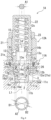
Fig. 1 is a sectional view showing a relief valve with a check function according toEmbodiment 1 of the present invention. -
Fig. 2 is a sectional view showing relief operation of the relief valve with a check function ofFig. 1 . -
Fig. 3 is a sectional view showing check operation of the relief valve with a check function ofFig. 1 . -
Fig. 4 is a sectional view showing a relief valve with a check function according toEmbodiment 2 of the present invention. -
Fig. 5 is a sectional view showing a relief valve with a check function according toEmbodiment 3 of the present invention. - Hereinafter, relief valves with a
check function Embodiments 1 to 3 according to the present invention are described by referring to the aforementioned drawings. The concept of the direction used in the following description is merely used for convenience in description, and should not be understood to limit the orientation or the like of the configuration of the invention to the described direction. Also, each of the relief valves with arelief function - A hydraulic circuit includes a
relief valve 1 as shown inFig. 1 . As the pressure of hydraulic fluid of afirst port 2 exceeds a predetermined pressure (namely, relief pressure), therelief valve 1 flows the hydraulic fluid from thefirst port 2 to asecond port 3. Also, when the pressure of the hydraulic fluid of thefirst port 2 is lower than the pressure of thesecond port 3, therelief valve 1 flows the hydraulic fluid from thesecond port 3 to thefirst port 2. In the present embodiment, thefirst port 2 is, for example, an actuator port, and thesecond port 3 is a tank port. More specifically, therelief valve 1 includes avalve block 11, ahousing 12, aseat member 13, arelief valve body 14, afirst biasing member 15, acheck valve body 16, and asecond biasing member 17. - The
valve block 11 is a block body to which thehousing 12 is to be attached. More specifically, thevalve block 11 has avalve hole 11a, afirst passage 11b, and asecond passage 11c. Thevalve hole 11a is a bottomed hole formed along an axial line L1. In the bottom surface that defines thevalve hole 11a, thefirst port 2 is formed. Thefirst passage 11b connects to thevalve hole 11a via thefirst port 2. In the inner peripheral surface that defines thevalve hole 11a, thesecond port 3 is formed. Thesecond passage 11c connects to thevalve hole 11a via thesecond port 3. - The
housing 12 accommodates therein theseat member 13, therelief valve body 14, thefirst biasing member 15, thecheck valve body 16, and thesecond biasing member 17. Also, thehousing 12 has abody 21, anadjustment plug 22, and alocknut 23. More specifically, thehousing 12 is formed to have, for example, a topped cylindrical shape. Then, thehousing 12 is inserted through thevalve hole 11a with an opening 12a being directed to thefirst port 2. Therefore, the interior of thehousing 12 connects to thefirst port 2 via the opening 12a of thehousing 12. - The
body 21 is inserted through thevalve hole 11a with one end part which is an end part of one side in the axial direction being directed to thefirst port 2. More specifically, thebody 21 is formed to have a cylindrical shape. And, thebody 21 is screwed with thevalve block 11. Also, the inner hole of thebody 21 has anopening hole 21a and aninner space 21b. Theopening hole 21a is formed in the one end part that is an end part of one side in the axial direction of thebody 21. Also, theopening hole 21a is formed to have a smaller diameter than theinner space 21b. And, in thebody 21, acheck valve seat 21c is formed to surround theopening hole 21a. Also, in theinner space 21b, astep part 21e is formed in a middle portion in the axial direction, and theinner space 21b is formed to have a small diameter on one side in the axial direction from thestep part 21e compared with the other side in the axial direction. Further, in the outer peripheral surface of thebody 21, a plurality ofcommunication passages 21d are formed in a portion of one side in the axial direction. The plurality ofcommunication passages 21d radially penetrate thebody 21. And, the plurality ofcommunication passages 21d form acheck passage 24 together with theopening hole 21a and theinner space 21b. That is, thecheck passage 24 is a passage that runs from the plurality of communication passages 21da to theopening hole 21a through theinner space 21b. The one end part of thebody 21 is formed to have a tapered shape that is tapered toward one side in the axial direction in the present embodiment. Thebody 21 is inserted into thevalve hole 11a such that the one end part seals the periphery of thefirst port 2, and is screwed with thevalve block 11. Also, theopening hole 21a is located opposite to thefirst port 2, and the plurality ofcommunication passages 21d are located at positions corresponding to thesecond port 3. Therefore, theopening hole 21a connects to thefirst port 2, and the plurality ofcommunication passages 21d connect to thesecond port 3. - The adjustment plug 22 which is one example of an adjustment member is provided to be capable of advancing and retracting with respect to the
body 21. More specifically, theadjustment plug 22 is formed to have a topped cylindrical shape. An opening side portion of theadjustment plug 22 is screwed in thebody 21. That is, the adjustment plug 22 advances and retracts axially with respect to thebody 21 by being rotated about the axial line (coincident with the axial line L1 in the present embodiment). In the present embodiment, theadjustment plug 22 is configured to be rotatable with the use of a jig such as a spanner, a hexagon wrench, and a screw driver. - The
locknut 23 restricts advance and retraction of theadjustment plug 22 with respect to thebody 21. More specifically, thelocknut 23 is formed to have an annular shape. And, thelocknut 23 is screwed with a middle portion of theadjustment plug 22. Thelocknut 23 is fastened to come into contact with an other end part that is an end part of the other side in the axial direction of thebody 21. As a result, advance and retraction in the axial direction of theadjustment plug 22 with respect to thebody 21 is restricted. On the other hand, thelocknut 23 is loosened to leave the other end part of thebody 21. Thus, advance and retraction in the axial direction of theadjustment plug 22 with respect to thebody 21 is allowed. - The
seat member 13 is provided inside thehousing 12. Also, in theseat member 13, arelief passage 25 is formed. Therelief passage 25 connects to each of thefirst port 2 and thesecond port 3. More specifically, theseat member 13 is formed to have a cylindrical shape. Still more specifically, a middle portion of theseat member 13 is formed to have a larger diameter than a one-end side portion in the axial direction, and have a smaller diameter than an other end side portion in the axial direction. Also, in aninner hole 13a of theseat member 13, a portion of one side in the axial direction forms apassage portion 13b, and a portion of the other side in the axial direction forms avalve insertion portion 13c. Thepassage portion 13b is formed to have a smaller diameter than thevalve insertion portion 13c. And, around the portion where thepassage portion 13b opens to thevalve insertion portion 13c, arelief valve seat 13e is formed. Also, in the middle portion of theseat member 13, a plurality of throughpassages 13f are formed. The plurality of throughpassages 13f form therelief passage 25 in theseat member 13 together with theinner hole 13a. That is, therelief passage 25 is a passage that runs from thepassage portion 13b to the plurality of throughpassages 13f through thevalve insertion portion 13c. Further, in the outer peripheral surface of the one-end side portion in the axial direction of theseat member 13, a plurality ofcommunication holes 13g are formed. The plurality ofcommunication holes 13g radially penetrate the one-end side portion in the axial direction of theseat member 13. Further, in the other end side portion in the axial direction of theseat member 13, a plurality ofcommunication passages 13h are formed around theinner hole 13a. Thecommunication passages 13h form a large-diameter portion of theseat member 13 parallel with the axial line L1. Also, thecommunication passages 13h form a restrictor. - The
seat member 13 configured as described above is located in a middle portion of thehousing 12. More specifically, theseat member 13 is located on one side in the axial direction from theadjustment plug 22 inside thebody 21. And, theseat member 13 is fixed inside thehousing 12 by making the large-diameter portion be screwed with the inner peripheral surface of thebody 21, and engaged with thestep part 21e. Accordingly, the interior of thehousing 12 is partitioned by theseat member 13 into avalve space 12b on one side in the axial direction and a firstspring accommodating space 12c on the other side in the axial direction. Also, theseat member 13 is located such that the opening of one side in the axial direction is directed to thefirst port 2. Accordingly, anannular space 12d is formed between the middle portion ofseat member 13 and thebody 21, in thevalve space 12b. And, the throughpassages 13f connect to thesecond port 3 via theannular space 12d. Since the opening of one side in the axial direction is directed to thefirst port 2, thepassage portion 13b of therelief passage 25 connects to thefirst port 2. And, thecommunication passages 13h connect thevalve space 12b and the firstspring accommodating space 12c. - The
relief valve body 14 can be unseated from or seated on theseat member 13. Also, by unseating from or seating on theseat member 13, therelief passage 25 opens or closes. Further, therelief valve body 14 receives the pressure of thefirst port 2 in the direction of opening the relief passage 25 (hereinafter, referred to as "first opening direction"). More specifically, therelief valve body 14 is inserted through thevalve insertion portion 13c. Therelief valve body 14 is seated on therelief valve seat 13e by a distalend side portion 14a located on one side in the axial direction. Also, therelief valve body 14 is capable of sliding in the axial direction. Therefore, therelief valve body 14 is unseated from or seated on therelief valve seat 13e to open or close therelief passage 25. Also, therelief valve body 14 is configured as follows in the present embodiment. - That is, the
relief valve body 14 is a direct-acting valve body formed of a solid member, and is formed to have a cylindrical shape. And, a middle portion of therelief valve body 14 is slidably supported by theseat member 13. Also, in therelief valve body 14, the distalend side portion 14a located on one side in the axial direction is formed to have a smaller diameter than the middle portion. The distalend side portion 14a of therelief valve body 14 is formed to have an acuminate shape. And, the distalend side portion 14a of therelief valve body 14 is seated on therelief valve seat 13e in such a manner that it sticks into thepassage portion 13b. Therefore, the distalend side portion 14a of therelief valve body 14 forms apressure receiving part 14c. That is, therelief valve body 14 receives the hydraulic pressure of thepassage portion 13b by thepressure receiving part 14c. More specifically, therelief valve body 14 receives the hydraulic pressure of thepassage portion 13b in the portion corresponding to thepassage portion 13b (see a first pressure receiving area A1 of thepressure receiving part 14c inFig. 1 ). Since the hydraulic fluid of thefirst port 2 is guided to thepassage portion 13b, therelief valve body 14 receives the hydraulic pressure of thefirst port 2 in thepressure receiving part 14c of the distalend side portion 14a. Therelief valve body 14 receives from the hydraulic fluid the load that is the product of the first pressure receiving area A1 of thepressure receiving part 14c multiplied by the pressure of thefirst port 2 in the first opening direction. Therefore, therelief valve body 14 is unseated from or seated on theseat member 13 in accordance with the pressure of thefirst port 2. Also, therelief valve body 14 has aspring bearing part 14b on the outer peripheral surface of a proximal end side portion located on the other side in the axial direction. - The
first biasing member 15 biases therelief valve body 14 in the direction of closing the relief passage 25 (hereinafter, referred to as "first closing direction") against the pressure of thefirst port 2. More specifically, the first biasingmember 15 is a spring member. In the present embodiment, the first biasingmember 15 is a compression coil spring. Thefirst biasing member 15 is accommodated in the firstspring accommodating space 12c of the housing 12 (namely, inside the adjustment plug 22) in a compressed state. More specifically, the first biasingmember 15 comes into contact with thespring bearing part 14b of therelief valve body 14 at one end part, and comes into contact with the ceiling surface of theadjustment plug 22 at the other end part. Thus, the first biasingmember 15 biases therelief valve body 14 in the first closing direction (namely, one side in the axial direction) against the pressure of thefirst port 2. - Also, in the first biasing
member 15, the biasing force is adjusted by advancing or retracting theadjustment plug 22. More specifically, by loosening thelocknut 23 and rotating theadjustment plug 22, it is possible to advance or retract theadjustment plug 22. As a result, the compression amount of the first biasingmember 15 is adjusted. The biasing force of the first biasingmember 15 is adjusted by the compression amount of the first biasingmember 15. - The
check valve body 16 opens or closes thecheck passage 24. Also, thecheck valve body 16 receives the pressure of thesecond port 3 in the direction of opening the check passage 24 (hereinafter, referred to as "second opening direction"). Still more specifically, thecheck valve body 16 is accommodated in thehousing 12, more specifically in thebody 21. And, thecheck valve body 16 is slidably supported by theseat member 13. More specifically, thecheck valve body 16 is slidably attached outside theseat member 13. And, thecheck valve body 16 is unseated from or seated on thecheck valve seat 21c by sliding. Thecheck valve body 16 is seated on thecheck valve seat 21c to close thecheck passage 24. Also, thecheck valve body 16 has acommunication passage 16a. Thecommunication passage 16a guides the hydraulic fluid flowing from thefirst port 2 to therelief passage 25 of theseat member 13 in the condition that thecheck valve body 16 closes thecheck passage 24. In the present embodiment, thecheck valve body 16 is formed in the following manner. - That is, the
check valve body 16 is formed to have a cylindrical shape. And, thecheck valve body 16 allows insertion of theseat member 13 in the inner hole thereof in a slidable manner. And, thecheck valve body 16 is accommodated in theinner space 21b of thebody 21. Also, thecheck valve body 16 forms an annular in-valve passage 26 between thecheck valve body 16 and thebody 21. The in-valve passage 26 connects to thesecond port 3 via the plurality ofcommunication passages 21d. And, the in-valve passage 26 forms thecheck passage 24 together with theopening hole 21a and the plurality ofcommunication passages 21d. Also, in thecheck valve body 16, one end part that is an open end part of one side in the axial direction is tapered toward one side in the axial direction. Thecheck valve body 16 closes thecheck passage 24 by seating the one end part on thecheck valve seat 21c. Also, thecheck valve body 16 leaves thecheck valve seat 21c by sliding on the other side in the axial direction along theseat member 13. Thus, thecheck passage 24 opens. Also, thecheck valve body 16 receives the pressure in the one end part from the fluid flowing in thecheck passage 24. That is, thecheck valve body 16 receives the pressure of thesecond port 3 in the second opening direction in the one end part. - Further, the
check valve body 16 has thecommunication passage 16a, a middle part 16b, and a large-diameter part 16c in the inner hole of thecheck valve body 16. Thecommunication passage 16a, the middle part 16b, and the large-diameter part 16c are located in this order from one side in the axial direction, and have increasing diameters in the order of thecommunication passage 16a, the middle part 16b, and the large-diameter part 16c. Thecommunication passage 16a having the smallest diameter among these three parts connects to thefirst port 2 via theopening hole 21a. In the middle part 16b, one end part in the axial direction of theseat member 13 is slidably inserted. Also, in the large-diameter part 16c, the middle portion of theseat member 13 is slidably inserted in a sealed state. Accordingly, thecheck valve body 16 is stably supported at two sites of the middle part 16b and the large-diameter part 16c which are sliding parts. Also, between the large-diameter part 16c and the one end side portion in the axial direction of theseat member 13, and around the middle portion of theseat member 13, a secondspring accommodating space 16d of an annular shape is formed. The secondspring accommodating space 16d connects to therelief passage 25 via thecommunication holes 13g. Therefore, hydraulic fluid from thefirst port 2 flows into the secondspring accommodating space 16d via therelief passage 25. Accordingly, thecheck valve body 16 receives, in its inner peripheral surface, the pressure of thefirst port 2 in the direction of closing the check passage 24 (hereinafter, referred to as "second closing direction"). - As described above, the
check valve body 16 receives, in its one end part, the pressure of thesecond port 3 in the second opening direction, and receives, in its inner peripheral surface, the pressure of thefirst port 2 in the second closing direction. And, thecheck valve body 16 receives, in thepressure receiving part 16e of the one end part, the pressures of theports ports pressure receiving part 16e, corresponds to an area obtained by subtracting the area of a bore D2 of theopening hole 21a from the area of a hole diameter D1 of the large-diameter part 16c. Thecheck valve body 16 receives from the hydraulic fluid the load that is the product of the second pressure receiving area A2 multiplied by differential pressure Δp obtained by subtracting the pressure of thefirst port 2 from the pressure of thesecond port 3, in the second opening direction. - The
second biasing member 17 biases thecheck valve body 16 in the second closing direction against the pressure of thesecond port 3. More specifically, the second biasingmember 17 is a spring member. In the present embodiment, the second biasingmember 17 is a compression coil spring. Thesecond biasing member 17 is accommodated in the secondspring accommodating space 16d in thecheck valve body 16 in a compressed state. More specifically, end parts of the second biasingmember 17 are brought into contact with theseat member 13 and thecheck valve body 16, respectively. Thus, the second biasingmember 17 biases thecheck valve body 16 in the second closing direction (that is, one side in the axial direction) against the pressure of thesecond port 3. - In the
relief valve 1, the hydraulic fluid to be guided to thefirst port 2 is guided to thepassage portion 13b of therelief passage 25 via theopening hole 21a and thecommunication passage 16a. And, as the pressure of thefirst port 2 exceeds a relief pressure, therelief valve 1 operates as follows. That is, as shown inFig. 2 , therelief valve body 14 is pushed up against the biasing force of the first biasingmember 15, and therelief valve body 14 leaves therelief valve seat 13e. Thus, therelief passage 25 opens. As a result, thefirst port 2 connects to thesecond port 3 via therelief passage 25. Then, hydraulic fluid of thefirst port 2 is discharged to the second port 3 (see an arrow Y1 inFig. 2 ). At the time of pushing up of therelief valve body 14, the first biasingmember 15 is compressed, and thus the firstspring accommodating space 12c is contracted. As a result, the hydraulic fluid is discharged into thevalve space 12b from the firstspring accommodating space 12c via thecommunication passages 13h. Since thecommunication passages 13h form a restrictor, therelief valve body 14 is pushed up gently. Therefore, therelief passage 25 can be opened gently, so that occurrence of hunting can be prevented. - Also, in the
relief valve 1, the aforementioned relief pressure can be adjusted in the following manner. That is, in therelief valve 1, by loosening thelocknut 23, the adjustment plug 22 advances or retracts. In the present embodiment, the adjustment plug 22 advances or retracts by being rotated with a jig. By advancing or retracting theadjustment plug 22 in this manner, it is possible to vary the compression amount of the first biasingmember 15. As a result, the biasing force with which the first biasingmember 15 biases therelief valve body 14 changes, and the relief pressure can be adjusted. - Also, in the
relief valve 1, the hydraulic fluid is guided from thesecond port 3 to thecheck passage 24, and the hydraulic fluid from thefirst port 2 is guided to the secondspring accommodating space 16d via therelief passage 25. And, as the pressure of thefirst port 2 becomes lower than the pressure of thesecond port 3, thecheck valve body 16 operates as follows. That is, as the load that thecheck valve body 16 receives by differential pressure Δp becomes larger than the biasing force of the second biasingmember 17, thecheck valve body 16 is pushed up. As a result, thecheck valve body 16 leaves thecheck valve seat 21c. Thus, thecheck passage 24 opens. As a result, thesecond port 3 connects to thefirst port 2 via thecheck passage 24. Then, the hydraulic fluid of thesecond port 3 is supplied to the first port 2 (see an arrow Y2 inFig. 3 ). - In the
relief valve 1 of the present embodiment, by advancing or retracting theadjustment plug 22, the pressure at which therelief valve body 14 starts leaving therelief valve seat 13e, namely, the relief pressure can be adjusted from outside. - Also, in the
relief valve 1 of the present embodiment, by seating of therelief valve body 14 on theseat member 13 provided in thehousing 12, therelief passage 25 is closed. Therefore, the twovalve bodies relief valve body 14 and thecheck valve body 16 can operate independently from each other. That is, since only thecheck valve body 16 can be independently operated, it is possible to improve the responsiveness of thecheck valve body 16 as compared with the case where the twovalve bodies relief valve body 14 and thecheck valve body 16 operate independently from each other, it is possible to reduce the weight of the part that operates in the check operation. Therefore, it is possible to improve the responsiveness of thecheck valve body 16 as compared with the case where the twovalve bodies relief valve 1, thecheck valve body 16 is slidably supported by theseat member 13. As a result, theseat member 13 functions as a guide for thecheck valve body 16, so that it is possible to prevent the number of parts from increasing. - In the
relief valve 1 of the present embodiment, thecheck valve body 16 is slidably supported by theseat member 13 in two sliding parts of the middle part 16b and the large-diameter part 16c. And, the second biasingmember 17 is accommodated in the secondspring accommodating space 16d formed between the middle part 16b and the large-diameter part 16c. Therefore, it is possible to form therelief valve 1 compactly. - Also, in the
relief valve 1 of the present embodiment, since therelief valve body 14 is a direct-acting valve body, it is possible to reduce the number of parts as compared with a differential-acting valve body. Further, in therelief valve 1 of the present embodiment, therelief valve body 14, the first biasingmember 15, thecheck valve body 16, and the second biasingmember 17 are assembled to thehousing 12. Therefore, therelief valve 1 can be provided as a cartridge. Therefore, it is possible to improve the portability and the assemblability to thevalve block 11 of therelief valve 1. - A
relief valve 1A ofEmbodiment 2 resembles therelief valve 1 ofEmbodiment 1 in configuration. Therefore, the configuration of therelief valve 1A ofEmbodiment 2 is described mainly about the point different from that of therelief valve 1 ofEmbodiment 1, and the same configuration is denoted by the same reference numeral, and the description is omitted. The same applies also to therelief valve 1B ofEmbodiment 3. - The
relief valve 1A ofEmbodiment 2 shown inFig. 4 includes thevalve block 11A, ahousing 12A, theseat member 13, therelief valve body 14, the first biasingmember 15, thecheck valve body 16, and the second biasingmember 17. Thevalve block 11A has thevalve hole 11a, thefirst passage 11b, and thesecond passage 11c. And, in thevalve block 11A, the check valve seat 11d is formed around thefirst port 2. And, thefirst port 2 and thesecond port 3 are connected by thevalve hole 11a. Also, thevalve hole 11a forms acheck passage 24A. - The
housing 12A is formed to have a short length in the axial direction compared with thehousing 12 ofEmbodiment 1. More specifically, a body 21A is formed to have a short length in the axial direction compared with thebody 21 ofEmbodiment 1. Therefore, one end part of the body 21A is located close to the other end side in the axial direction, compared with the one end part of thebody 21 ofEmbodiment 1. Further, one end side portion of thecheck valve body 16 projects from theopening hole 21a of the body 21A. And, thecheck valve body 16 is seated on the check valve seat 11d of thevalve block 11A. Also, thecheck valve body 16 is arranged in theopening hole 21a with a clearance from the body 21A. Therefore, theannular space 12d connects to thesecond port 3 via theopening hole 21a. - In the
relief valve 1A configured as described above, as the pressure of thefirst port 2 exceeds the relief pressure, therelief valve body 14 leaves therelief valve seat 13e, and therelief passage 25 opens. As therelief passage 25 opens, thefirst port 2 and thesecond port 3 connect with each other via thevalve space 12b via theopening hole 21a. And, hydraulic fluid of thefirst port 2 is discharged to thesecond port 3. On the other hand, as the pressure of thefirst port 2 becomes smaller than the pressure of thesecond port 3, and the load that thecheck valve body 16 receives by differential pressure Δp becomes larger than the biasing force of the second biasingmember 17, thecheck valve body 16 leaves the check valve seat 11d, and thecheck passage 24A opens. As a result, thefirst port 2 and thesecond port 3 connect with each other via thecheck passage 24A, and the hydraulic fluid of thesecond port 3 is supplied to thefirst port 2. - The
relief valve 1A ofEmbodiment 2 configured as described above exerts the same operation and effect as therelief valve 1 ofEmbodiment 1. - The
relief valve 1B ofEmbodiment 3 shown inFig. 5 includes thevalve block 11, thehousing 12, theseat member 13, arelief valve body 14B, the first biasingmember 15, thecheck valve body 16, the second biasingmember 17, arod 18, and aspring bearing member 19. Therelief valve body 14B is a differential-acting valve body having abackpressure chamber 27 to which the hydraulic fluid flowing in therelief passage 25 is guided. More specifically, therelief valve body 14B is formed to have a bottomed cylindrical shape. And, therelief valve body 14B seats its bottom part (namely, the distalend side portion 14a) on therelief valve seat 13e to close therelief passage 25. Also, in therelief valve body 14B, a throughhole 14d is formed along its axial direction (coincident with the axial line L1 in the present embodiment). The throughhole 14d faces with thepassage portion 13b of therelief passage 25. Therod 18 is inserted in aninner hole 14e of therelief valve body 14B in a sealed state. Therod 18 is arranged such that the distal end portion inserted into theinner hole 14e is apart from the bottom part of therelief valve body 14B. Thus, in theinner hole 14e of therelief valve body 14, thebackpressure chamber 27 is formed. Thebackpressure chamber 27 connects to thepassage portion 13b of therelief passage 25 via the throughhole 14d. Therefore, to thebackpressure chamber 27, the pressure of thefirst port 2 is guided. Also, a proximal end part of therod 18 is in contact with the ceiling surface of theadjustment plug 22. In this manner, therod 18 is prevented from getting out of therelief valve body 14. Also, thespring bearing member 19 is inserted into therod 18, and is in contact with the proximal end of therelief valve body 14B. And, thespring bearing member 19 bears one end part of the first biasingmember 15. - In the
relief valve 1B configured as described above, the same relief operation and check operation as in therelief valve 1 ofEmbodiment 1 are executed, and therelief valve 1B has the following function in the relief operation. Therelief valve body 14B receives a load in the first closing direction from the hydraulic fluid guided to thebackpressure chamber 27 from thefirst port 2 via therelief passage 25. Therefore, the load that therelief valve body 14B receives from the hydraulic fluid of thepassage portion 13b is partially cancelled. Due to this cancelling, the load in the opening direction that acts on therelief valve body 14B becomes the load that is the product of a third pressure receiving area A3 obtained by subtracting the cross section of a hole diameter D4 of thebackpressure chamber 27 from the opening area of a pore size D3 of anopening 13d, multiplied by the pressure of thefirst port 2. Therefore, the load in the opening direction that acts on therelief valve body 14B can be controlled to small, and the seat diameter of therelief valve body 14 can be made large, as compared with the direct-acting relief valve body. As a result, in therelief valve 1, it is possible to achieve a large flow amount as compared with therelief valve 1 of the direct-acting type. - Besides the above, the
relief valve 1B of the third embodiment exerts the same operation and effect as therelief valve 1 ofEmbodiment 1. - In the
relief valves Embodiments 1 to 3, for example, thefirst port 2 is an actuator port and thesecond port 3 is a tank port, however, the ports are not necessarily be such ports. While thecheck valve body 16 is inserted outside theseat member 13, thecheck valve body 16 may be inserted insideseat member 13. Also, in therelief valves Embodiments 1 to 3, theelements 13 to 17 are accommodated in thehousing 12 to form a cartridge, however, they are not necessarily be formed into a cartridge. That is, theelements 13 to 17 may be assembled to thehousing 12 that is assembled to thevalve block 11. - Also, in the
relief valves Embodiments 1 to 3, the adjustment plug 22 advances or retracts with respect to thebody 21 by being rotated, however, theadjustment plug 22 may advance or retract by pushing or drawing theadjustment plug 22. Also, the adjustment member is not limited to theadjustment plug 22, but may be an adjustment screw. The adjustment screw is capable of advancing or retracting with respect to thebody 21 by being rotated as with the case of theadjustment plug 22. And, by advancing or retracting the adjustment screw, the relief pressure is adjusted. - Various modifications and other embodiments of the present invention will be apparent to those skilled in the art from the above description. According, the above description should be interpreted merely as illustration, and is provided for the purpose of indicating the best mode for carrying out the present invention to those skilled in the art. The details of the structure and/or the function can be substantially changed without departing from the spirit of the present invention.
Claims (7)
- A relief valve with a check function of relieving hydraulic fluid from a first port to a second port, the relief valve with a check function comprising:a housing having a body, and an adjustment member provided to be capable of advancing and retracting with respect to the body;a seat member provided in the body, the seat member being formed with a relief passage connecting to each of the first port and the second port;a relief valve body that is unseated from or seated on the seat member to open or close the relief passage, the relief valve body receiving pressure of the first port in a direction of opening the relief passage;a first biasing member that biases the relief valve body against the pressure of the first port, with a biasing force being adjusted by advance or retraction of the adjustment member;a check valve body that opens or closes a check passage connecting to each of the first port and the second port, the check valve body receiving pressure of the second port in a direction of opening the check passage; anda second biasing member that biases the check valve body against the pressure of the second port.
- The relief valve with a check function according to claim 1, wherein the check valve body is slidably supported by the seat member.
- The relief valve with a check function according to claim 2, whereinthe check valve body has a communication passage, and is inserted outside the seat member, andthe communication passage guides hydraulic fluid flowing from the first port to the relief passage of the seat member in a state that the check valve body closes the check passage.
- The relief valve with a check function according to claim 3, whereinthe check valve body is slidably supported by the seat member in at least two sliding parts spaced from each other, andthe second biasing member is accommodated between the two sliding parts in the check valve body.
- The relief valve with a check function according to any one of claims 1 to 4, wherein the relief valve body has a pressure-receiving part that receives pressure of the first port, and is a direct-acting valve body having the pressure-receiving part formed of a solid member.
- The relief valve with a check function according to any one of claims 1 to 4, wherein the relief valve body is a differential-acting valve body having a backpressure chamber to which hydraulic fluid flowing in the relief passage is guided.
- The relief valve with a check function according to any one of claims 1 to 6, wherein the relief valve body, the first biasing member, the check valve body, and the second biasing member are assembled to the housing.
Applications Claiming Priority (2)
| Application Number | Priority Date | Filing Date | Title |
|---|---|---|---|
| JP2020218894A JP7668638B2 (en) | 2020-12-28 | 2020-12-28 | Relief valve with check function |
| PCT/JP2021/039542 WO2022145124A1 (en) | 2020-12-28 | 2021-10-26 | Relief valve with check function |
Publications (2)
| Publication Number | Publication Date |
|---|---|
| EP4269848A1 true EP4269848A1 (en) | 2023-11-01 |
| EP4269848A4 EP4269848A4 (en) | 2024-11-20 |
Family
ID=82260348
Family Applications (1)
| Application Number | Title | Priority Date | Filing Date |
|---|---|---|---|
| EP21914985.3A Withdrawn EP4269848A4 (en) | 2020-12-28 | 2021-10-26 | Relief valve with check function |
Country Status (5)
| Country | Link |
|---|---|
| US (1) | US20240052938A1 (en) |
| EP (1) | EP4269848A4 (en) |
| JP (1) | JP7668638B2 (en) |
| CN (1) | CN116324246A (en) |
| WO (1) | WO2022145124A1 (en) |
Family Cites Families (24)
| Publication number | Priority date | Publication date | Assignee | Title |
|---|---|---|---|---|
| US3913601A (en) * | 1974-05-31 | 1975-10-21 | Tiona Betts Inc | Pressure relief and check valve combination |
| US3980095A (en) * | 1975-02-10 | 1976-09-14 | Mcavoy Dennis J | Power transmission |
| JPS5410430A (en) * | 1977-06-24 | 1979-01-26 | Caterpillar Mitsubishi Ltd | Compound safety valve having functions of relief valve and make up valve |
| JPS595259Y2 (en) * | 1979-01-12 | 1984-02-16 | 東芝機械株式会社 | Make-up valve that also serves as a relief valve |
| WO1986004657A1 (en) * | 1985-02-08 | 1986-08-14 | Dibartolo Ernest A | Direct-acting, differential piston relief valve |
| JPH0721974Y2 (en) | 1989-02-08 | 1995-05-17 | ダイキン工業株式会社 | Check relief valve with bypass function |
| US5050637A (en) * | 1990-05-23 | 1991-09-24 | Kawasaki Jukogyo Kabushiki Kaisha | Relief valve |
| US5050636A (en) * | 1990-10-17 | 1991-09-24 | Kawasaki Jukogyo Kabushiki Kaisha | Relief valve |
| JP3452474B2 (en) * | 1997-11-28 | 2003-09-29 | 株式会社ナブコ | Balance type relief valve |
| JP2908435B1 (en) * | 1998-06-12 | 1999-06-21 | 川崎重工業株式会社 | Relief valve |
| JP2003185042A (en) | 2001-12-17 | 2003-07-03 | Shin Caterpillar Mitsubishi Ltd | Line relief valve |
| US7086388B2 (en) * | 2003-08-04 | 2006-08-08 | Delphi Technologies, Inc. | Combination valve for fuel system |
| KR100586023B1 (en) * | 2004-02-12 | 2006-06-01 | 볼보 컨스트럭션 이키프먼트 홀딩 스웨덴 에이비 | Relief valve |
| ITMO20040045A1 (en) * | 2004-02-27 | 2004-05-27 | Salami Spa | MAXIMUM PRESSURE VALVE GROUP |
| US7392823B2 (en) * | 2004-12-01 | 2008-07-01 | Parker-Hannifin Corporation | Combination valve |
| WO2006134588A1 (en) * | 2005-06-16 | 2006-12-21 | Raval A.C.S. Ltd. | Double check valve for a fuel system |
| US7806142B2 (en) * | 2007-06-27 | 2010-10-05 | Teleflex Canada Inc. | Combined relief valve and check valve |
| US20110240897A1 (en) * | 2008-10-08 | 2011-10-06 | Robert Bosch Gmbh | Pressure Limiting And Suction Valve Unit |
| JP5775368B2 (en) * | 2011-06-08 | 2015-09-09 | 川崎重工業株式会社 | Relief valve |
| CN204114257U (en) * | 2014-01-27 | 2015-01-21 | 东正科技有限公司 | A kind of regulating type inhalation valve |
| FR3039620B1 (en) * | 2015-07-28 | 2017-08-25 | Poclain Hydraulics Ind | PRESSURE LIMITATION DEVICE, IN PARTICULAR FOR A VEHICLE ASSISTANCE SYSTEM |
| CN111094817B (en) * | 2017-09-21 | 2021-09-10 | 克斯美库股份有限公司 | Cylinder device with sequence valve |
| CN108547820A (en) * | 2018-07-16 | 2018-09-18 | 贵州大学 | A kind of box-like orifice valve of pressure difference control group |
| CN112096682B (en) * | 2020-09-30 | 2021-11-19 | 潍柴动力股份有限公司 | Pilot-operated type electric proportional high-pressure overflow valve |
-
2020
- 2020-12-28 JP JP2020218894A patent/JP7668638B2/en active Active
-
2021
- 2021-10-26 CN CN202180070974.5A patent/CN116324246A/en active Pending
- 2021-10-26 WO PCT/JP2021/039542 patent/WO2022145124A1/en not_active Ceased
- 2021-10-26 US US18/259,387 patent/US20240052938A1/en not_active Abandoned
- 2021-10-26 EP EP21914985.3A patent/EP4269848A4/en not_active Withdrawn
Also Published As
| Publication number | Publication date |
|---|---|
| WO2022145124A1 (en) | 2022-07-07 |
| JP7668638B2 (en) | 2025-04-25 |
| EP4269848A4 (en) | 2024-11-20 |
| JP2022103964A (en) | 2022-07-08 |
| CN116324246A (en) | 2023-06-23 |
| US20240052938A1 (en) | 2024-02-15 |
Similar Documents
| Publication | Publication Date | Title |
|---|---|---|
| KR100764119B1 (en) | Pilot Poppet Relief Valve | |
| US7159611B2 (en) | Inline flow control device | |
| JP2009529731A (en) | Depressurizing regulator with adjustable function | |
| EP1727013A2 (en) | Fluid flow regulator with overpressure relief function | |
| EP3961074B1 (en) | Relief valve | |
| CN115735075B (en) | Overflow valve | |
| US5143115A (en) | Bi-directional pressure relief valve | |
| US20150167856A1 (en) | Relief valve | |
| US5699829A (en) | Fluid control valve with soft startup | |
| US20240052938A1 (en) | Relief valve with check function | |
| KR20030017324A (en) | Relief valve and hydraulic device having the relief valve | |
| US4415001A (en) | Pressure rise rate limiter valve | |
| KR102667662B1 (en) | Combination valve | |
| US6220565B1 (en) | Safety valve assembly | |
| EP2708970B1 (en) | Pressure regulator | |
| KR100965041B1 (en) | Actuator control unit | |
| US4199004A (en) | Relief and make-up valve assembly | |
| WO2023150448A1 (en) | Pressure relief valve with a reverse free flow configuration integrated therewith | |
| US12271212B2 (en) | Counterbalance valve with enhanced pressure sensing features | |
| US10801615B2 (en) | Pressure limiting device, in particular for a hydraulic assist system for vehicles | |
| CN219529431U (en) | Overflow valve | |
| GB2197433A (en) | Fluid control valves | |
| US4984603A (en) | Flow control valve assembly | |
| CN111279105A (en) | Relief valve | |
| EP3680491B1 (en) | Control valve |
Legal Events
| Date | Code | Title | Description |
|---|---|---|---|
| STAA | Information on the status of an ep patent application or granted ep patent |
Free format text: STATUS: THE INTERNATIONAL PUBLICATION HAS BEEN MADE |
|
| PUAI | Public reference made under article 153(3) epc to a published international application that has entered the european phase |
Free format text: ORIGINAL CODE: 0009012 |
|
| STAA | Information on the status of an ep patent application or granted ep patent |
Free format text: STATUS: REQUEST FOR EXAMINATION WAS MADE |
|
| 17P | Request for examination filed |
Effective date: 20230728 |
|
| AK | Designated contracting states |
Kind code of ref document: A1 Designated state(s): AL AT BE BG CH CY CZ DE DK EE ES FI FR GB GR HR HU IE IS IT LI LT LU LV MC MK MT NL NO PL PT RO RS SE SI SK SM TR |
|
| DAV | Request for validation of the european patent (deleted) | ||
| DAX | Request for extension of the european patent (deleted) | ||
| A4 | Supplementary search report drawn up and despatched |
Effective date: 20241018 |
|
| RIC1 | Information provided on ipc code assigned before grant |
Ipc: F16K 17/196 20060101ALI20241014BHEP Ipc: F16K 47/00 20060101ALI20241014BHEP Ipc: F16K 17/06 20060101AFI20241014BHEP |
|
| STAA | Information on the status of an ep patent application or granted ep patent |
Free format text: STATUS: THE APPLICATION IS DEEMED TO BE WITHDRAWN |
|
| 18D | Application deemed to be withdrawn |
Effective date: 20250507 |