EP4269832A1 - Active shock absorber device for a motor vehicle with integrated control unit - Google Patents
Active shock absorber device for a motor vehicle with integrated control unit Download PDFInfo
- Publication number
- EP4269832A1 EP4269832A1 EP23169139.5A EP23169139A EP4269832A1 EP 4269832 A1 EP4269832 A1 EP 4269832A1 EP 23169139 A EP23169139 A EP 23169139A EP 4269832 A1 EP4269832 A1 EP 4269832A1
- Authority
- EP
- European Patent Office
- Prior art keywords
- control unit
- shock absorber
- absorber device
- force
- power supply
- Prior art date
- Legal status (The legal status is an assumption and is not a legal conclusion. Google has not performed a legal analysis and makes no representation as to the accuracy of the status listed.)
- Pending
Links
Images


Classifications
-
- B—PERFORMING OPERATIONS; TRANSPORTING
- B60—VEHICLES IN GENERAL
- B60G—VEHICLE SUSPENSION ARRANGEMENTS
- B60G17/00—Resilient suspensions having means for adjusting the spring or vibration-damper characteristics, for regulating the distance between a supporting surface and a sprung part of vehicle or for locking suspension during use to meet varying vehicular or surface conditions, e.g. due to speed or load
- B60G17/015—Resilient suspensions having means for adjusting the spring or vibration-damper characteristics, for regulating the distance between a supporting surface and a sprung part of vehicle or for locking suspension during use to meet varying vehicular or surface conditions, e.g. due to speed or load the regulating means comprising electric or electronic elements
-
- B—PERFORMING OPERATIONS; TRANSPORTING
- B60—VEHICLES IN GENERAL
- B60G—VEHICLE SUSPENSION ARRANGEMENTS
- B60G17/00—Resilient suspensions having means for adjusting the spring or vibration-damper characteristics, for regulating the distance between a supporting surface and a sprung part of vehicle or for locking suspension during use to meet varying vehicular or surface conditions, e.g. due to speed or load
- B60G17/06—Characteristics of dampers, e.g. mechanical dampers
-
- F—MECHANICAL ENGINEERING; LIGHTING; HEATING; WEAPONS; BLASTING
- F16—ENGINEERING ELEMENTS AND UNITS; GENERAL MEASURES FOR PRODUCING AND MAINTAINING EFFECTIVE FUNCTIONING OF MACHINES OR INSTALLATIONS; THERMAL INSULATION IN GENERAL
- F16F—SPRINGS; SHOCK-ABSORBERS; MEANS FOR DAMPING VIBRATION
- F16F9/00—Springs, vibration-dampers, shock-absorbers, or similarly-constructed movement-dampers using a fluid or the equivalent as damping medium
- F16F9/32—Details
- F16F9/3207—Constructional features
-
- B—PERFORMING OPERATIONS; TRANSPORTING
- B60—VEHICLES IN GENERAL
- B60G—VEHICLE SUSPENSION ARRANGEMENTS
- B60G13/00—Resilient suspensions characterised by arrangement, location or type of vibration dampers
- B60G13/001—Arrangements for attachment of dampers
- B60G13/005—Arrangements for attachment of dampers characterised by the mounting on the axle or suspension arm of the damper unit
-
- B—PERFORMING OPERATIONS; TRANSPORTING
- B60—VEHICLES IN GENERAL
- B60G—VEHICLE SUSPENSION ARRANGEMENTS
- B60G15/00—Resilient suspensions characterised by arrangement, location or type of combined spring and vibration damper, e.g. telescopic type
- B60G15/02—Resilient suspensions characterised by arrangement, location or type of combined spring and vibration damper, e.g. telescopic type having mechanical spring
-
- B—PERFORMING OPERATIONS; TRANSPORTING
- B60—VEHICLES IN GENERAL
- B60G—VEHICLE SUSPENSION ARRANGEMENTS
- B60G15/00—Resilient suspensions characterised by arrangement, location or type of combined spring and vibration damper, e.g. telescopic type
- B60G15/02—Resilient suspensions characterised by arrangement, location or type of combined spring and vibration damper, e.g. telescopic type having mechanical spring
- B60G15/06—Resilient suspensions characterised by arrangement, location or type of combined spring and vibration damper, e.g. telescopic type having mechanical spring and fluid damper
- B60G15/062—Resilient suspensions characterised by arrangement, location or type of combined spring and vibration damper, e.g. telescopic type having mechanical spring and fluid damper the spring being arranged around the damper
-
- B—PERFORMING OPERATIONS; TRANSPORTING
- B60—VEHICLES IN GENERAL
- B60G—VEHICLE SUSPENSION ARRANGEMENTS
- B60G17/00—Resilient suspensions having means for adjusting the spring or vibration-damper characteristics, for regulating the distance between a supporting surface and a sprung part of vehicle or for locking suspension during use to meet varying vehicular or surface conditions, e.g. due to speed or load
- B60G17/015—Resilient suspensions having means for adjusting the spring or vibration-damper characteristics, for regulating the distance between a supporting surface and a sprung part of vehicle or for locking suspension during use to meet varying vehicular or surface conditions, e.g. due to speed or load the regulating means comprising electric or electronic elements
- B60G17/0152—Resilient suspensions having means for adjusting the spring or vibration-damper characteristics, for regulating the distance between a supporting surface and a sprung part of vehicle or for locking suspension during use to meet varying vehicular or surface conditions, e.g. due to speed or load the regulating means comprising electric or electronic elements characterised by the action on a particular type of suspension unit
-
- B—PERFORMING OPERATIONS; TRANSPORTING
- B60—VEHICLES IN GENERAL
- B60G—VEHICLE SUSPENSION ARRANGEMENTS
- B60G17/00—Resilient suspensions having means for adjusting the spring or vibration-damper characteristics, for regulating the distance between a supporting surface and a sprung part of vehicle or for locking suspension during use to meet varying vehicular or surface conditions, e.g. due to speed or load
- B60G17/06—Characteristics of dampers, e.g. mechanical dampers
- B60G17/08—Characteristics of fluid dampers
-
- B—PERFORMING OPERATIONS; TRANSPORTING
- B60—VEHICLES IN GENERAL
- B60G—VEHICLE SUSPENSION ARRANGEMENTS
- B60G3/00—Resilient suspensions for a single wheel
- B60G3/02—Resilient suspensions for a single wheel with a single pivoted arm
- B60G3/04—Resilient suspensions for a single wheel with a single pivoted arm the arm being essentially transverse to the longitudinal axis of the vehicle
- B60G3/06—Resilient suspensions for a single wheel with a single pivoted arm the arm being essentially transverse to the longitudinal axis of the vehicle the arm being rigid
-
- F—MECHANICAL ENGINEERING; LIGHTING; HEATING; WEAPONS; BLASTING
- F16—ENGINEERING ELEMENTS AND UNITS; GENERAL MEASURES FOR PRODUCING AND MAINTAINING EFFECTIVE FUNCTIONING OF MACHINES OR INSTALLATIONS; THERMAL INSULATION IN GENERAL
- F16F—SPRINGS; SHOCK-ABSORBERS; MEANS FOR DAMPING VIBRATION
- F16F13/00—Units comprising springs of the non-fluid type as well as vibration-dampers, shock-absorbers, or fluid springs
- F16F13/005—Units comprising springs of the non-fluid type as well as vibration-dampers, shock-absorbers, or fluid springs comprising both a wound spring and a damper, e.g. a friction damper
- F16F13/007—Units comprising springs of the non-fluid type as well as vibration-dampers, shock-absorbers, or fluid springs comprising both a wound spring and a damper, e.g. a friction damper the damper being a fluid damper
-
- F—MECHANICAL ENGINEERING; LIGHTING; HEATING; WEAPONS; BLASTING
- F16—ENGINEERING ELEMENTS AND UNITS; GENERAL MEASURES FOR PRODUCING AND MAINTAINING EFFECTIVE FUNCTIONING OF MACHINES OR INSTALLATIONS; THERMAL INSULATION IN GENERAL
- F16F—SPRINGS; SHOCK-ABSORBERS; MEANS FOR DAMPING VIBRATION
- F16F15/00—Suppression of vibrations in systems; Means or arrangements for avoiding or reducing out-of-balance forces, e.g. due to motion
- F16F15/02—Suppression of vibrations of non-rotating, e.g. reciprocating systems; Suppression of vibrations of rotating systems by use of members not moving with the rotating systems
- F16F15/03—Suppression of vibrations of non-rotating, e.g. reciprocating systems; Suppression of vibrations of rotating systems by use of members not moving with the rotating systems using magnetic or electromagnetic means
-
- F—MECHANICAL ENGINEERING; LIGHTING; HEATING; WEAPONS; BLASTING
- F16—ENGINEERING ELEMENTS AND UNITS; GENERAL MEASURES FOR PRODUCING AND MAINTAINING EFFECTIVE FUNCTIONING OF MACHINES OR INSTALLATIONS; THERMAL INSULATION IN GENERAL
- F16F—SPRINGS; SHOCK-ABSORBERS; MEANS FOR DAMPING VIBRATION
- F16F9/00—Springs, vibration-dampers, shock-absorbers, or similarly-constructed movement-dampers using a fluid or the equivalent as damping medium
- F16F9/32—Details
- F16F9/44—Means on or in the damper for manual or non-automatic adjustment; such means combined with temperature correction
- F16F9/46—Means on or in the damper for manual or non-automatic adjustment; such means combined with temperature correction allowing control from a distance, i.e. location of means for control input being remote from site of valves, e.g. on damper external wall
- F16F9/461—Means on or in the damper for manual or non-automatic adjustment; such means combined with temperature correction allowing control from a distance, i.e. location of means for control input being remote from site of valves, e.g. on damper external wall characterised by actuation means
- F16F9/462—Rotary actuation means
-
- F—MECHANICAL ENGINEERING; LIGHTING; HEATING; WEAPONS; BLASTING
- F16—ENGINEERING ELEMENTS AND UNITS; GENERAL MEASURES FOR PRODUCING AND MAINTAINING EFFECTIVE FUNCTIONING OF MACHINES OR INSTALLATIONS; THERMAL INSULATION IN GENERAL
- F16F—SPRINGS; SHOCK-ABSORBERS; MEANS FOR DAMPING VIBRATION
- F16F9/00—Springs, vibration-dampers, shock-absorbers, or similarly-constructed movement-dampers using a fluid or the equivalent as damping medium
- F16F9/32—Details
- F16F9/56—Means for adjusting the length of, or for locking, the spring or damper, e.g. at the end of the stroke
-
- B—PERFORMING OPERATIONS; TRANSPORTING
- B60—VEHICLES IN GENERAL
- B60G—VEHICLE SUSPENSION ARRANGEMENTS
- B60G2200/00—Indexing codes relating to suspension types
- B60G2200/10—Independent suspensions
- B60G2200/14—Independent suspensions with lateral arms
- B60G2200/142—Independent suspensions with lateral arms with a single lateral arm, e.g. MacPherson type
-
- B—PERFORMING OPERATIONS; TRANSPORTING
- B60—VEHICLES IN GENERAL
- B60G—VEHICLE SUSPENSION ARRANGEMENTS
- B60G2202/00—Indexing codes relating to the type of spring, damper or actuator
- B60G2202/20—Type of damper
- B60G2202/24—Fluid damper
-
- B—PERFORMING OPERATIONS; TRANSPORTING
- B60—VEHICLES IN GENERAL
- B60G—VEHICLE SUSPENSION ARRANGEMENTS
- B60G2202/00—Indexing codes relating to the type of spring, damper or actuator
- B60G2202/30—Spring/Damper and/or actuator Units
- B60G2202/31—Spring/Damper and/or actuator Units with the spring arranged around the damper, e.g. MacPherson strut
- B60G2202/312—The spring being a wound spring
-
- B—PERFORMING OPERATIONS; TRANSPORTING
- B60—VEHICLES IN GENERAL
- B60G—VEHICLE SUSPENSION ARRANGEMENTS
- B60G2202/00—Indexing codes relating to the type of spring, damper or actuator
- B60G2202/30—Spring/Damper and/or actuator Units
- B60G2202/31—Spring/Damper and/or actuator Units with the spring arranged around the damper, e.g. MacPherson strut
- B60G2202/314—The spring being a pneumatic spring
-
- B—PERFORMING OPERATIONS; TRANSPORTING
- B60—VEHICLES IN GENERAL
- B60G—VEHICLE SUSPENSION ARRANGEMENTS
- B60G2202/00—Indexing codes relating to the type of spring, damper or actuator
- B60G2202/40—Type of actuator
- B60G2202/41—Fluid actuator
- B60G2202/416—Fluid actuator using a pump, e.g. in the line connecting the lower chamber to the upper chamber of the actuator
-
- B—PERFORMING OPERATIONS; TRANSPORTING
- B60—VEHICLES IN GENERAL
- B60G—VEHICLE SUSPENSION ARRANGEMENTS
- B60G2202/00—Indexing codes relating to the type of spring, damper or actuator
- B60G2202/40—Type of actuator
- B60G2202/42—Electric actuator
-
- B—PERFORMING OPERATIONS; TRANSPORTING
- B60—VEHICLES IN GENERAL
- B60G—VEHICLE SUSPENSION ARRANGEMENTS
- B60G2202/00—Indexing codes relating to the type of spring, damper or actuator
- B60G2202/40—Type of actuator
- B60G2202/42—Electric actuator
- B60G2202/422—Linear motor
-
- B—PERFORMING OPERATIONS; TRANSPORTING
- B60—VEHICLES IN GENERAL
- B60G—VEHICLE SUSPENSION ARRANGEMENTS
- B60G2204/00—Indexing codes related to suspensions per se or to auxiliary parts
- B60G2204/10—Mounting of suspension elements
- B60G2204/12—Mounting of springs or dampers
- B60G2204/129—Damper mount on wheel suspension or knuckle
-
- B—PERFORMING OPERATIONS; TRANSPORTING
- B60—VEHICLES IN GENERAL
- B60G—VEHICLE SUSPENSION ARRANGEMENTS
- B60G2204/00—Indexing codes related to suspensions per se or to auxiliary parts
- B60G2204/10—Mounting of suspension elements
- B60G2204/20—Mounting of accessories, e.g. pump, compressor
- B60G2204/202—Mounting of accessories, e.g. pump, compressor of cables
-
- B—PERFORMING OPERATIONS; TRANSPORTING
- B60—VEHICLES IN GENERAL
- B60G—VEHICLE SUSPENSION ARRANGEMENTS
- B60G2500/00—Indexing codes relating to the regulated action or device
- B60G2500/10—Damping action or damper
-
- B—PERFORMING OPERATIONS; TRANSPORTING
- B60—VEHICLES IN GENERAL
- B60G—VEHICLE SUSPENSION ARRANGEMENTS
- B60G2500/00—Indexing codes relating to the regulated action or device
- B60G2500/30—Height or ground clearance
-
- B—PERFORMING OPERATIONS; TRANSPORTING
- B60—VEHICLES IN GENERAL
- B60G—VEHICLE SUSPENSION ARRANGEMENTS
- B60G2600/00—Indexing codes relating to particular elements, systems or processes used on suspension systems or suspension control systems
- B60G2600/09—Feedback signal
-
- B—PERFORMING OPERATIONS; TRANSPORTING
- B60—VEHICLES IN GENERAL
- B60G—VEHICLE SUSPENSION ARRANGEMENTS
- B60G2600/00—Indexing codes relating to particular elements, systems or processes used on suspension systems or suspension control systems
- B60G2600/12—Sampling or average detecting; Addition or substraction
- B60G2600/124—Error signal
-
- B—PERFORMING OPERATIONS; TRANSPORTING
- B60—VEHICLES IN GENERAL
- B60G—VEHICLE SUSPENSION ARRANGEMENTS
- B60G2600/00—Indexing codes relating to particular elements, systems or processes used on suspension systems or suspension control systems
- B60G2600/72—Cooling or warming means
Definitions
- the invention concerns an active shock absorber device for a motor vehicle, in particular a sports car.
- the body of a motor vehicle is normally suspended in relation to the wheels via suspension devices.
- Each of the suspension devices usually includes a shock absorber device, in turn including a spring and a damper, for example a helical spring and a damper or shock absorber, for example a gas one, more precisely of the double-cylinder (bi-tube) type or single-cylinder (single tube) type or with remote hydraulic valves and gas tank.
- a shock absorber device in turn including a spring and a damper, for example a helical spring and a damper or shock absorber, for example a gas one, more precisely of the double-cylinder (bi-tube) type or single-cylinder (single tube) type or with remote hydraulic valves and gas tank.
- the hydraulic damper has an external casing and a shaft with a piston that is axially mobile in relation to the external casing.
- An axial end of the shaft and the external casing are, respectively, fixed to the body and to an element of the suspension device, for example a suspension arm. In this way, the movement of the shaft in relation to the external casing corresponds to a movement of the body in relation to the suspension arm.
- the suspension arm follows, though not necessarily rigidly, a movement of the wheel to which it is coupled. Therefore, the movement of the wheel caused by the contact with the road surface is transmitted to the suspension arm with the result of a relative movement of the shaft in relation to the external casing fixed to the suspension arm.
- the piston cooperates with a fluid wherein the piston is immersed inside the external casing, thus damping the movement of the shaft itself.
- the helical spring has two axial ends respectively fixed to the body and to the suspension arm. In this way, the movement of the body in relation to the suspension arm corresponds to an extension or elastic compression of the spring.
- the spring may be coaxial to the shaft.
- the shock absorber device may be an active one, i.e., comprising a control apparatus or, more precisely, an apparatus for generating a force configured to actively control the movement of the body in relation to the suspension arm, in particular generating and controlling a force applied to the body, independently of the movement imposed on the wheels by the road surface and transmitted to the body via the suspension devices.
- the control apparatus may be of various types; for example, some control apparatuses pertinent to shock absorber devices, so-called adaptive ones, control the damping offered by the shock absorber device, regulating the fluid-dynamic cooperation of the piston with the fluid inside the external casing.
- Other, purely active control apparatuses pertinent to shock absorber devices directly impose a controlled movement on the body relative to the suspension arm via servoactuators, for example, electric, hydraulic, pneumatic, or electro-hydraulic ones.
- an adaptive shock absorber device may be that wherein the piston comprises continuously adjustable spool valves to adjust the flow of fluid through the piston during the movement of the shaft.
- the spool valves are electrically driven, i.e., by means of an electric motor, for example an electric stepper motor.
- an electric motor for example an electric stepper motor.
- One example of a purely active shock absorber device may be that including a hydraulic actuator for moving the shaft or the body in relation to the suspension arm, wherein the internal pressure is adjusted via a hydraulic machine, for example a pump, driven by an electric motor.
- One preferred example of a purely active shock absorber device may be that wherein the electric motor directly drives the shaft through a transmission, in particular comprising a succession of gears, a chain or belt, or wherein the electric motor moves the body in relation to the suspension arm.
- the shock absorber device may also include any combination of the above-mentioned technologies, so that, for example, the shock absorber device may include the hydraulic actuator and the spool valves on the piston or the spool valves on the piston and the electric motor driving the shaft via the transmission.
- the active shock absorber device whether adaptive or purely active, comprises at least one motor for delivering torque or a force, based on the type of motor, and an adjustment device configured to use the torque or the force delivered by the motor to adjust a force applied to the shaft or, more generally, exerted by the shock absorber device, i.e., more precisely to adjust or at least influence the movement of the shaft.
- the force applied or exerted may be a damping force, i.e., a force countering movement of the shaft, or an actuating force, i.e., a force synchronising with the movement of the shaft.
- the torque or force delivered by the motor, on which the damping force or the applied actuating force depends, is controlled via electric signals coming from a control unit of the motor vehicle, for example, as a function of the quantities detected by transducers and indicating a pace of the motor vehicle.
- the motor may be electric and, in more detail, be controlled or supplied via high-voltage electric signals, i.e., electric signals with a voltage greater than or equal to 36 volts, more preferably greater than or equal to 48 volts.
- One purpose of this invention is to satisfy the need described above, preferably in a simple and reliable way.
- shock absorber device as defined in claim 1.
- the reference number 1 is used to indicate, as a whole, a motor vehicle.
- the motor vehicle 1 has a body 2, i.e., a structural assembly including a frame and a bodywork, and at least one wheel 3 coupled to the body 2.
- a body 2 i.e., a structural assembly including a frame and a bodywork, and at least one wheel 3 coupled to the body 2.
- the body 2 defines or surrounds the passenger compartment of the motor vehicle 1.
- the motor vehicle 1 also comprises a suspension 4, through which the wheel 3 is coupled to the body 2.
- the suspension 4 comprises multiple suspension elements coupled to the wheel 3, including a suspension arm 5 illustrated in Figure 1 .
- the wheel 3 defines an unsuspended mass of the motor vehicle 1, i.e., a body arranged in direct contact with the road; therefore, during the travel of the motor vehicle 1, the wheel 3 moves as a function of the features of the road with which it is in contact.
- the movements of the wheel 3 are transmitted to the suspension elements since the latter are coupled to the wheel 3.
- the suspension elements move as a function of the movements of the wheel 3.
- the arm 5 rotates around an axis H, so that the movements of the wheel 3 may cause corresponding rotations of the arm 5.
- the suspension elements may have movements relative to the wheel 3, although this is not, generally, necessary.
- the motor vehicle 1 also comprises a shock absorber device or assembly 6 that is part of the suspension 4; the shock absorber device 6 is configured to suspend the body 2 in relation to one of the suspension elements, in particular in relation to the arm 5.
- the body 2 defines a mass suspended by the shock absorber device 6 relative to the unsuspended mass.
- the body 2 may have a movement relative to the wheel 3, while being coupled to it via the same shock absorber device 6 and the arm 5.
- the shock absorber device 6 reacts to the relative movements between the body 2 and the wheel 3 exerting a force countering a force acting on the wheel 3 due to the contact between the wheel 3 and the road, so that a force resulting from the overlapping of the other two forces mentioned and having, conveniently, a reduced modulus compared to the force acting on the wheel 3 is actually transmitted to the body 2.
- the force exerted by the shock absorber device 6 is preferably such as to brake the relative movement of the body 2 compared to the wheel 3, dissipating energy, for example as a result of an impact between the wheel 3 and the road or of a transfer of the load of the motor vehicle 1, for example, occurring when the motor vehicle 1 takes a curve, or during acceleration or braking of the motor vehicle 1; in this way, the movements of the wheel 3 are not transmitted to the body 2 with a medium or high frequency.
- the shock absorber device 6 comprises a spring support 7, a spring 8, and a shock absorber or damping device 9.
- the spring 8 suspends the body 2 in relation to one of the suspension elements, in particular in relation to the arm 5.
- the damper 9 performs the function of dissipating energy.
- the spring 8 may be, for example, a metallic spring, in particular a helical spring, or a fluid spring without any loss of generality.
- the spring 8 has an axis K, i.e., it extends axially along the axis K.
- the spring 8 extends axially between two ends 8a, 8b, respectively fixed to the spring support 7 and to the body 2.
- the end 8a is directly fixed to the spring support 7.
- the end 8b may be fixed to the body 2 indirectly, as appears in Figure 1 and as will be detailed below.
- the damping device 9 is configured to at least damp the movement of the wheel 3, more precisely relative to the body 2, exerting a damping force in response to the movement of the wheel 3.
- the damping force corresponds to a relative force exerted on the body 2 or on the wheel 3, in particular according to classical mechanics, more specifically Eulerian mechanics.
- the damping device 9 may also be used to exert an actuating force, i.e., to amplify or increase the movement of the wheel 3 relative to the body 2, for example by distancing the body 2 from the wheel 3, or even to generate or impose the movement of the wheel 3 in relation to the body 2.
- the damping device 9 may be part of a purely active shock absorber device.
- the actuating force corresponds to a relative force exerted on the body 2 or on the wheel 3, in particular according to classical mechanics, more specifically Eulerian mechanics.
- the damping device 9 comprises an external casing 10 extending axially between two ends 11, 12, of which the end 12 is fixed to one of the suspension elements, specifically the arm 5, in particular directly.
- the casing 10 is, more specifically, cylindrical.
- the casing 10 extends around the axis K, i.e., along the axis K.
- the spring 8 is coaxial with the casing 10 or with the damping device 9. More precisely, the spring 8 is arranged around the casing 10 or the damping device 9.
- the damping device 9 comprises, in detail, an internal cylinder not illustrated and completely filled with a fluid, in particular a liquid, more specifically an oil.
- the damping device 9 comprises, in addition, a shaft 13 and a piston not illustrated and fixed to the shaft 13 at one intermediate portion of the shaft 13.
- the shaft 13 is arranged along the axis K and can slide along the axis K in relation to the casing 10 inside the latter.
- the piston is configured to cooperate with the fluid in the internal cylinder.
- An axial movement of the shaft 13 corresponds, thus, to an interaction between the piston and the fluid. The interaction produces the damping force countering the axial movement of the shaft 13.
- the damping device 9 also comprises an attachment element 14 fixed to one end of the shaft 13; the attachment element 14 has a portion arranged between the shaft 13 and the body 2 and is fixed to the body 2, in particular using threaded elements not illustrated.
- the axial movement of the shaft 13 corresponds to an axial movement of the attachment element 14 and, thus, to an axial movement of the body 2.
- the shaft 13 moves axially in relation to the casing 10 and, thus, in relation to the suspension element or arm 5.
- the body 2 moves axially in relation to the suspension element or arm 5 in response to the axial movement of the shaft 13.
- the end 8b of the spring 8 is fixed to the attachment element 14, in particular directly.
- the spring 8 extends along the axis K between the spring support 7 and the attachment element 14.
- the end 8b is indirectly fixed to the body 2 via the attachment element 14.
- the axial movement of the attachment element 14 corresponding to the axial movement of the shaft 13 entails an extension or compression of the spring 8, which consequently reacts elastically.
- the spring support 7 is fixed relative to the casing 10. More precisely, the spring support 7 is fixed to the casing 10 at one intermediate portion of the casing 10 between the ends 11, 12.
- the spring support 7 has a through hole along the axis K.
- the casing 10 completely traverses the spring support 7 via the through hole along the axis K. In other words, the casing 10 extends along the axis K through the through hole.
- the movements of the wheel 3 are transmitted to the arm 5; the movement of the arm 5 causes a relative axial movement between the shaft 13 and the casing 10.
- the latter relative movement causes the production of the damping force as mentioned above.
- the body 2 moves rigidly together with the shaft 13, in particular via the attachment element 14 fixing the body 2 to the shaft 13 indirectly.
- the damping force corresponds to a relative movement between the arm 5 and the body 2 coupled via the shock absorber device 6.
- the shock absorber device 6 also comprises an electric motor 16, in particular an AC electric motor, for example an asynchronous motor. More precisely, the alternating current that supplies the electric motor 16 is a three-phase current, in particular with a nominal supply voltage between 36 and 52 volts, more specifically equal to 48 volts.
- the electric motor 16 may also function as a generator.
- the electric motor 16 is configured to output a torque or force, for example in its operation as motor, i.e., when it is supplied with electric current.
- the electric motor 16 has at least one stator portion 17 that is fixed relative to the casing 10.
- the shock absorber device 6 comprises a conversion or regulation or drive assembly 18 configured to use the torque or force provided by the electric motor 16 transforming it into a force exerted by or via the damping device 9, i.e., in other words to drive the damping device 9 so that the latter produces a force associated with or corresponding to the torque or the force provided by the motor.
- the force exerted via the damping device 9 is, in particular, an axial force, i.e., a force directed along the axis K.
- the force exerted via the damping device 9 may be a damping force or an actuating force.
- the damping force or the actuating force corresponds to a force exerted on the body 2 or on the wheel 3 via the damping device 9.
- the conversion assembly 18 produces the damping or drive force, as a function of the or in response to the torque or force provided by the electric motor 16.
- the conversion assembly 18 controls the damping device 9 using the torque or force provided by the electric motor 16, so that the damping or actuating force is exerted in correspondence with the torque or force provided.
- the conversion assembly 18 establishes a relation, in this case unique, between the torque or the force provided and the force exerted by the damping device 9.
- the conversion assembly 18 transforms the torque or force provided by the electric motor 16 into a force applied to the shaft 13 and, more particularly, directed along the axis K.
- the latter force on the shaft 13 may be the damping force, i.e., directed in contrast to the movement of the shaft 13, or the actuating force, i.e., directed concordant with the movement of the shaft 13.
- the conversion assembly 18 applies or transfers the torque or force provided by the electric motor 16 onto the shaft 13.
- the conversion assembly 18 may actually be produced in many ways, some already known.
- the conversion assembly 18 comprises a transmission configured to transfer the torque or force provided by the electric motor 16 to the shaft 13 mechanically, so that the shaft 13 moves axially in response to the torque or force provided by the electric motor 16.
- the transmission includes at least one mechanism for converting the rotary movement outputted by the electric motor 16 into a translating movement, such as a screw-nut mechanism or a mechanism with coupling between a worm screw and a helical wheel. The transmission confers the translating movement to the shaft 13, so that the shaft 13 translates along the axis K.
- the conversion assembly 18 comprises one or more servo valves and a hydraulic machine, for example a pump, driven using the electric motor 16, potentially by means of suitable transmissions.
- the pump is configured to supply liquid to the servo valves using at least one portion of the torque or force provided by the electric motor 16.
- the servo valves are controlled via the electric motor 16 and configured to distribute the liquid provided by the pump upstream and/or downstream of the piston inside the casing 10. Therefore, the servo valves and the pump define a system configured to change the pressure of the fluid inside the casing 10 upstream and/or downstream of the piston, so that the force along the axis K acting on the piston varies as a result. In this way, by adjusting the pressure upstream and/or downstream of the piston, the conversion assembly 18 applies the damping or actuating force coinciding with the force acting on the piston and, as a result, on the shaft 13.
- the conversion assembly 18 comprises one or more servo valves coupled to the piston and configured to enable the liquid inside the casing 10 to traverse the piston according to an adjustable flow via the servo valves.
- the servo valves can be adjusted using the electric motor 16.
- the servo valves have multiple openings and mobile shutters to adjust the blocking of the openings.
- the electric motor 16 is configured to move the mobile shutters via the torque or force provided by the electric motor 16 and transmitted to the mobile shutters via a suitable mechanical transmission, thus adjusting the degree to which the openings are blocked.
- the blocking of the openings determines the flow of liquid through the piston.
- the flow of liquid determines the damping force acting on the piston and, thus, on the shaft 13 as a result.
- the conversion assembly 18 comprises a mechanical transmission configured to transmit the torque or force provided by the electric motor 16 to the body 2 directly.
- the mechanical transmission supplied with the torque or force provided by the electric motor 16 moves the body 2 in relation to the suspension element or arm 5, causing a relative movement of the body 2 in relation to the suspension element or arm 5.
- the conversion assembly 18 indirectly controls the damping device 9 since the latter responds to the relative movement of the body 2 in relation to the suspension element or arm 5 with the damping force as a function of the torque or force provided by the electric motor 16.
- the mechanical transmission of the fourth example may be configured to move the spring support 7 and, as a result, the casing 10 in relation to the body 2. Moving the spring support 7, the arm 5 also moves towards the body 2.
- the damping or actuating force is a direct consequence of the torque or force provided by the electric motor 16 and is, therefore, dependent on the torque or force provided.
- the actuating force or the damping force is directed, in this case, according to the axis K.
- the shock absorber device 6 comprises a control unit 20 electrically connected to the electric motor 16, in particular via multiple wires 21, 22, 23, 26.
- the control unit 20 is integrated with the shock absorber device 6.
- the wires 21, 22, 23 represent, in detail, the three phases of the current suitable for supplying the electric motor 16.
- the wire 26, independently of the other wires 21, 22, 23, may represent a wire to convey a feedback signal to control, in a closed loop, the output speed from the electric motor 16 in response to the current to supply the electric motor 16.
- the feedback signal corresponds to a quantity detected and indicating the output speed from the electric motor 16.
- the electric motor 16 can be controlled by the control unit 20 via a power supply signal emitted by the control unit 20.
- the power supply signal is the electric current that supplies the electric motor 16, i.e., the current directed by the control unit 20 to the electric motor 20 through the wires 21, 22, 23.
- the torque or force provided by the electric motor 16 is the direct result of the power supply signal received by the electric motor 16.
- the torque or the force delivered corresponds to the power supply signal or is a function of the power supply signal.
- the control unit 20 is configured to emit the power supply signal as a function of a control signal coming from another control unit, for example that is part of the motor vehicle 1, and indicating a target value for the damping or actuating force.
- the target value may be an individual value, for example associated with a current moment, or variable over time, i.e., a temporal succession of target values.
- the control unit 20 is configured to receive the control signal, for example via a wire 27, in detail that is part of a CAN 12V network.
- wire 27 connects one control unit 20 with the other control unit of the motor vehicle 1.
- the control unit 20 is, additionally, electrically connected to the motor vehicle 1 via supply wires 24 and 25.
- the supply wire 24 comes, in particular, from a power source or is attached to the power source, for example a battery or volt generator 48.
- the wire 25 is a grounded wire.
- control unit 20 comprises an electrical connection to receive an electrical supply current.
- the electrical supply current in particular a direct current, may, in particular, have a voltage between 36 and 52 volts, preferably 48 volts.
- the target value of the damping or actuating force is preferably determined by the other control unit as a function of signals acquired via transducers and indicating parameters characterising the movement of the motor vehicle 1 in use.
- the actual methods with which the target value is determined are irrelevant for the purposes of the invention and may, besides, be considered as known. Therefore, these methods will not be described in detail.
- the control unit 20 processes the control signal using internal logics so as to determine and, consequently, emit the power supply signal corresponding to the target value, of which the control signal is descriptive.
- control unit 20 is configured to provide the power supply signal as a function of the control signal, so that the power supply signal provided corresponds to the target value for the required damping or actuating force.
- control chain in particular an open-loop one, so that the control signal indicating the target value is used by the control unit 20 to determine and emit a power supply signal so that the electric motor 16 provides torque or a force transformed by the conversion assembly 18 into a damping or actuating force corresponding to the target value.
- the damping or actuating force actually exerted by the shock absorber device 6 tends towards the target value, since the control unit 20 emits a power supply signal calibrated so that the torque or force provided by the electric motor 16 causes, via the conversion assembly 18, a damping or actuating force equal to the target value. In ideal conditions, the damping or actuating force will actually be equal to the target value. On the other hand, considering the non-ideal behaviour of the electric motor 16 and of the conversion assembly 18, the damping or actuating force will have a deviation from the target value, preferably negligible, although not necessarily.
- control unit 20 may comprise control logics in a closed loop to determine the power supply signal.
- control unit 20 would emit the power supply signal as a function of a difference between the target value and the actual damping or actuating force, for example measured using a specific sensor or observed starting from one or more quantities measured using sensors.
- the power supply signal could be proportional to the difference, or calculated according to a PID control law.
- control unit 20 would emit the power supply signal as a function of the control signal, so that the power supply signal corresponds or has a relation with the target value.
- the relation with the target value includes a dependence on the actual damping or actuating force contributing to form the difference or error.
- the shock absorber device 6 comprises a transducer, in particular a position transducer, more especially an encoder, configured to detect a quantity indicating a position of the shaft 13 in relation to the casing 10 and to generate a corresponding electric signal.
- the position transducer is electrically connected to the control unit 20, for example via the wire 26.
- the quantity detected is, specifically, indicative of the output speed from the electric motor 16. Therefore, the control unit 20 is configured to receive the electrical signal associated with the quantity detected.
- the damping or actuating force could potentially be observed by the control unit 20 starting from the electrical signal received, for example by making use of a stored mathematical model.
- the mathematical model would link the damping force to the dynamics of changing the position of the shaft 13.
- the mathematical model could be based on a theoretical model, on experimental data, or on both.
- a wire identified by the reference number 28 is an additional, precautionary grounded wire, which is useful, for example, if there is a loss of insulation of the electric motor 16.
- the control unit 20 preferably comprises a static power converter, in particular an inverter configured to convert direct current or a direct current signal into alternating current or an alternating current signal to supply the electric motor 16.
- a static power converter in particular an inverter configured to convert direct current or a direct current signal into alternating current or an alternating current signal to supply the electric motor 16.
- control unit 20 could comprise a logical block or logics configured to determine an additional control signal as a function of the control signal indicating the target value.
- the additional signal would be determined by the control unit 20 with a view to being converted into the power supply signal via the converter.
- the additional control signal would be calibrated so that the power supply signal from the conversion entailed that the power emitted by the electric motor 16 caused, via the conversion device 18, a damping or actuating force equal to the target value.
- the additional control signal could even coincide with the control signal indicating the target value, without any loss of generality.
- control unit 20 adjusts the frequency of the power supply signal via the converter as a function of the control signal indicating the target value.
- control unit 20 comprises a mapping to map the target value onto the frequency of the power supply signal. Therefore, the frequency of the power supply signal is adjusted by the control unit 20 based on the mapping.
- the mapping may be, for example, calibrated experimentally by associating the actual damping or actuating force exerted by the shock absorber device 6 or the damper 9 with the frequency of the power supply signal.
- the control unit 20 is coupled to the spring support 7 in a fixed position relative to the spring support 7.
- the coupling between the control unit 20 and the spring support 7 occurs using fastening elements, for example multiple screws.
- the control unit 20 is, preferably, directly fixed to the spring support 7, i.e., in direct contact with the spring support 7.
- the spring support 7 is, specifically, arranged between the spring 8 and the control unit 20 according to the axis K.
- control unit 20 comprises a printed circuit board 31 (otherwise known by the acronym PCB), which, in particular, defines the logics of the control unit 20.
- PCB printed circuit board 31
- the printed circuit board 31 comprises, preferably, at least three substantially rigid portions 32, 33, 34.
- Each of the portions 32, 33, 34 extends transversely or orthogonally to corresponding axes orthogonal to the axis K.
- the printed circuit board 31 comprises two flexible portions 35 that connect, respectively, the portions 32, 33 to the portion 34.
- the portion 34 has two opposite ends 34a, 34b according to a straight direction A, in particular transversal and more particularly orthogonal to the axis K.
- the portion 34 has another two opposite ends 34c, 34d according to an additional straight direction B orthogonal to the direction A and parallel to the axis K.
- the portions 32, 33 are, respectively, coupled or connected to the portion 34 at the ends 34a, 34b via the flexible portions 35.
- the printed circuit board 31 preferably consists of a single piece.
- the printed circuit board 31 is a single body, without interruptions, between the portions 32, 33, 34, 35.
- the portions 32, 33 are arranged transversely to the portion 34 so as to form an empty volume between the portions 32, 33 according to the direction A.
- the portions 32, 33 are orthogonal to the portion 34.
- the printed circuit board 31 has a Cor U-shaped configuration. This particular configuration enables the control unit 20 to stay inscribed in the spring support 7 or, more precisely, in the diameter of the spring support 7, with dimensions advantageously compatible with the spaces of a suspension.
- the portions 32, 33 are parallel or facing each other according to the direction A.
- the casing 10 preferably traverses the empty volume between the portions 32, 33.
- the printed circuit board 31 embraces the casing 10.
- the control unit 20 also comprises a casing 40 containing the printed circuit board 31.
- the casing 40 has a shape corresponding to that of the printed circuit board 31.
- the casing 40 comprises a coating portion 41 defining a seat shaped to receive the printed circuit board 31 via insertion along the axis K only.
- the printed circuit board 31 cannot be inserted inside the seat along directions transversal to the axis K.
- the casing 40 comprises a mask 42 such as, for example, a cover configured to be fixed to the coating portion 41, for example using fastening elements such as screws, so as to close the printed circuit board 31 inside the seat.
- a mask 42 such as, for example, a cover configured to be fixed to the coating portion 41, for example using fastening elements such as screws, so as to close the printed circuit board 31 inside the seat.
- the printed circuit board 31 cannot be extracted from the seat when the mask 42 is fixed to the coating portion 41.
- the mask 42 comprises a plate that is transversal and more precisely orthogonal to the axis K.
- the coating portion 41 is arranged between the mask 42 and the spring support 7 according to the axis K.
- the mask 42 has multiple through holes 43, in particular that have corresponding axes parallel to the axis K.
- the holes 43 are, respectively, traversed by the wires: 21, 22, 23, 24, 25, 26, 27, 28.
- the wires 23, 24, 25, 26, 27, 28 end, in particular, with connection portions to be connected to the printed circuit board 31.
- connection portions are terminals directly fixed to the printed circuit board 31.
- the printed circuit board 31 is preferably immersed or embedded in a resin contained in the casing 40.
- the resin is polymeric; more precisely, the resin is an epoxy resin.
- the resin completely envelops the printed circuit board 31.
- the resin is present on both sides of the printed circuit board 31 according to directions orthogonal to the axis K.
- the control unit 20 also preferably comprises a voltage-limiting element configured to limit the voltage of an electrical current directed by the electric motor 16 towards the motor vehicle 1 or, more precisely, towards the other control unit of the motor vehicle 1.
- the control unit 20 is configured to activate the voltage-limiting element so that the latter performs its function of limiting voltage, when the same control unit 20 does not receive electrical supply current, in particular via the wire 24, nor the control signal indicating the target value of the damping force, in particular via the wire 27.
- control unit 20 is configured to limit the voltage of an input electric current coming from the electric motor 16 when it does not receive either the supply current or the control signal indicating the target value of the damping or actuating force. For example, this happens when the movement of the suspension 4 generates a relative movement between the casing 10 and the shaft 13, thus generating a conducted rotation of the electric motor 16, which functions in this case as an electrical generator.
- the shock absorber device 6 is extremely compact and, as a result, safe.
- the position of the control unit 20 near the spring support 7 enables the wires 21, 22, 23 to be very short compared to corresponding wires to connect the electric motor 16 to the other control unit of the motor vehicle 1. This enables the electrical insulation of the wires 21, 22, 23 and reduces the risks of short circuits or malfunctions.
- the printed circuit board 31 has an optimal shape.
- the configuration with the three portions 32, 33, 34 and the flexible portions 35 enables the printed circuit board 31 to remain compact despite the relatively high number of components.
- the C- or U-shaped configuration of the printed circuit board 31 facilitates the dispersion of heat via heat exchanges between the casing 40 and the surrounding air, in particular by convection, and between the casing 40 and the other casing 10, in particular via conduction, which, preferably, are both made of aluminium.
- the resin wherein the printed circuit board 31 is embedded protects the printed circuit board 31 from the significant vibrations to which the shock absorber device 6 is subject.
- the resin constitutes an effective barrier against the infiltration of water and dust inside the casing 40.
- shock absorber device 6 According to the invention, and variations produced thereof, that, in any case, do not depart from the scope of protection defined by the claims.
- each range described must be interpreted as multiple, individual alternative values. Each individual numeric value within the range must be considered as specifically described even if not explicitly mentioned.
- shock absorber device 6 may also be considered as belonging to the suspension 4 and, more generally, to the motor vehicle 1.
Landscapes
- Engineering & Computer Science (AREA)
- Mechanical Engineering (AREA)
- General Engineering & Computer Science (AREA)
- Physics & Mathematics (AREA)
- Electromagnetism (AREA)
- Acoustics & Sound (AREA)
- Aviation & Aerospace Engineering (AREA)
- Vehicle Body Suspensions (AREA)
Abstract
Description
- This patent application claims priority from
Italian patent application no. 102022000008252 filed on April 27, 2022 - The invention concerns an active shock absorber device for a motor vehicle, in particular a sports car.
- As known, the body of a motor vehicle is normally suspended in relation to the wheels via suspension devices.
- Each of the suspension devices usually includes a shock absorber device, in turn including a spring and a damper, for example a helical spring and a damper or shock absorber, for example a gas one, more precisely of the double-cylinder (bi-tube) type or single-cylinder (single tube) type or with remote hydraulic valves and gas tank.
- The hydraulic damper has an external casing and a shaft with a piston that is axially mobile in relation to the external casing. An axial end of the shaft and the external casing are, respectively, fixed to the body and to an element of the suspension device, for example a suspension arm. In this way, the movement of the shaft in relation to the external casing corresponds to a movement of the body in relation to the suspension arm.
- The suspension arm follows, though not necessarily rigidly, a movement of the wheel to which it is coupled. Therefore, the movement of the wheel caused by the contact with the road surface is transmitted to the suspension arm with the result of a relative movement of the shaft in relation to the external casing fixed to the suspension arm.
- During the relative movement of the shaft, the piston cooperates with a fluid wherein the piston is immersed inside the external casing, thus damping the movement of the shaft itself.
- Similarly, the helical spring has two axial ends respectively fixed to the body and to the suspension arm. In this way, the movement of the body in relation to the suspension arm corresponds to an extension or elastic compression of the spring.
- For example, the spring may be coaxial to the shaft.
- In some cases, the shock absorber device may be an active one, i.e., comprising a control apparatus or, more precisely, an apparatus for generating a force configured to actively control the movement of the body in relation to the suspension arm, in particular generating and controlling a force applied to the body, independently of the movement imposed on the wheels by the road surface and transmitted to the body via the suspension devices.
- The control apparatus may be of various types; for example, some control apparatuses pertinent to shock absorber devices, so-called adaptive ones, control the damping offered by the shock absorber device, regulating the fluid-dynamic cooperation of the piston with the fluid inside the external casing. Other, purely active control apparatuses pertinent to shock absorber devices directly impose a controlled movement on the body relative to the suspension arm via servoactuators, for example, electric, hydraulic, pneumatic, or electro-hydraulic ones.
- One example of an adaptive shock absorber device may be that wherein the piston comprises continuously adjustable spool valves to adjust the flow of fluid through the piston during the movement of the shaft. The spool valves are electrically driven, i.e., by means of an electric motor, for example an electric stepper motor. Clearly, adjusting the obstruction of the flow via the spool valves directly influences the damping of the shaft's movement, but does not generate, in itself, the movement of the shaft.
- One example of a purely active shock absorber device may be that including a hydraulic actuator for moving the shaft or the body in relation to the suspension arm, wherein the internal pressure is adjusted via a hydraulic machine, for example a pump, driven by an electric motor.
- One preferred example of a purely active shock absorber device may be that wherein the electric motor directly drives the shaft through a transmission, in particular comprising a succession of gears, a chain or belt, or wherein the electric motor moves the body in relation to the suspension arm.
- Of course, the shock absorber device may also include any combination of the above-mentioned technologies, so that, for example, the shock absorber device may include the hydraulic actuator and the spool valves on the piston or the spool valves on the piston and the electric motor driving the shaft via the transmission.
- In any case, the active shock absorber device, whether adaptive or purely active, comprises at least one motor for delivering torque or a force, based on the type of motor, and an adjustment device configured to use the torque or the force delivered by the motor to adjust a force applied to the shaft or, more generally, exerted by the shock absorber device, i.e., more precisely to adjust or at least influence the movement of the shaft.
- The force applied or exerted may be a damping force, i.e., a force countering movement of the shaft, or an actuating force, i.e., a force synchronising with the movement of the shaft.
- The torque or force delivered by the motor, on which the damping force or the applied actuating force depends, is controlled via electric signals coming from a control unit of the motor vehicle, for example, as a function of the quantities detected by transducers and indicating a pace of the motor vehicle.
- In some cases, the motor may be electric and, in more detail, be controlled or supplied via high-voltage electric signals, i.e., electric signals with a voltage greater than or equal to 36 volts, more preferably greater than or equal to 48 volts.
- In these cases, there is a need to improve the safety and/or the configuration of the electrical connections or components, in particular focusing on dimensions.
- One purpose of this invention is to satisfy the need described above, preferably in a simple and reliable way.
- The purpose is achieved with a shock absorber device as defined in claim 1.
- The dependent claims define particular embodiments of the invention.
- Below, an embodiment of the invention will be described to better understand the same by way of non-limiting example and with reference to the attached drawings in which:
-
Figure 1 is a schematic perspective view of a portion of a motor vehicle comprising a shock absorber device according to the invention; -
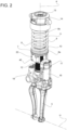
Figure 2 is a perspective view, on an enlarged scale, of the shock absorber device inFigure 1 , -
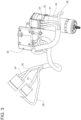
Figure 3 is an additional, perspective view of the shock absorber device with its wiring, and -
Figure 4 is an exploded view, on an even more enlarged scale, of a control unit of the shock absorber device. - In
Figure 1 , the reference number 1 is used to indicate, as a whole, a motor vehicle. - Like all motor vehicles, the motor vehicle 1 has a
body 2, i.e., a structural assembly including a frame and a bodywork, and at least onewheel 3 coupled to thebody 2. - The
body 2 defines or surrounds the passenger compartment of the motor vehicle 1. - The motor vehicle 1 also comprises a
suspension 4, through which thewheel 3 is coupled to thebody 2. - As known, the
suspension 4 comprises multiple suspension elements coupled to thewheel 3, including asuspension arm 5 illustrated inFigure 1 . - The
wheel 3 defines an unsuspended mass of the motor vehicle 1, i.e., a body arranged in direct contact with the road; therefore, during the travel of the motor vehicle 1, thewheel 3 moves as a function of the features of the road with which it is in contact. - The movements of the
wheel 3 are transmitted to the suspension elements since the latter are coupled to thewheel 3. In other words, the suspension elements move as a function of the movements of thewheel 3. - In detail, the
arm 5 rotates around an axis H, so that the movements of thewheel 3 may cause corresponding rotations of thearm 5. Thus, in general, the suspension elements may have movements relative to thewheel 3, although this is not, generally, necessary. - The motor vehicle 1 also comprises a shock absorber device or
assembly 6 that is part of thesuspension 4; theshock absorber device 6 is configured to suspend thebody 2 in relation to one of the suspension elements, in particular in relation to thearm 5. - Thus, the
body 2 defines a mass suspended by theshock absorber device 6 relative to the unsuspended mass. - Thanks to the
shock absorber device 6, thebody 2 may have a movement relative to thewheel 3, while being coupled to it via the sameshock absorber device 6 and thearm 5. Theshock absorber device 6 reacts to the relative movements between thebody 2 and thewheel 3 exerting a force countering a force acting on thewheel 3 due to the contact between thewheel 3 and the road, so that a force resulting from the overlapping of the other two forces mentioned and having, conveniently, a reduced modulus compared to the force acting on thewheel 3 is actually transmitted to thebody 2. The force exerted by theshock absorber device 6 is preferably such as to brake the relative movement of thebody 2 compared to thewheel 3, dissipating energy, for example as a result of an impact between thewheel 3 and the road or of a transfer of the load of the motor vehicle 1, for example, occurring when the motor vehicle 1 takes a curve, or during acceleration or braking of the motor vehicle 1; in this way, the movements of thewheel 3 are not transmitted to thebody 2 with a medium or high frequency. - In other words, the movements of the
wheel 3 are only partially transmitted, or in a dampened way, to thebody 2. - The
shock absorber device 6 comprises aspring support 7, aspring 8, and a shock absorber ordamping device 9. - The
spring 8 suspends thebody 2 in relation to one of the suspension elements, in particular in relation to thearm 5. Thedamper 9 performs the function of dissipating energy. - The
spring 8 may be, for example, a metallic spring, in particular a helical spring, or a fluid spring without any loss of generality. - The
spring 8 has an axis K, i.e., it extends axially along the axis K. Thespring 8 extends axially between twoends spring support 7 and to thebody 2. In particular, theend 8a is directly fixed to thespring support 7. Theend 8b may be fixed to thebody 2 indirectly, as appears inFigure 1 and as will be detailed below. - The damping
device 9 is configured to at least damp the movement of thewheel 3, more precisely relative to thebody 2, exerting a damping force in response to the movement of thewheel 3. - Clearly, the damping force corresponds to a relative force exerted on the
body 2 or on thewheel 3, in particular according to classical mechanics, more specifically Eulerian mechanics. - As will be clearer from below, the damping
device 9 may also be used to exert an actuating force, i.e., to amplify or increase the movement of thewheel 3 relative to thebody 2, for example by distancing thebody 2 from thewheel 3, or even to generate or impose the movement of thewheel 3 in relation to thebody 2. - In other words, the damping
device 9 may be part of a purely active shock absorber device. - Of course, even the actuating force corresponds to a relative force exerted on the
body 2 or on thewheel 3, in particular according to classical mechanics, more specifically Eulerian mechanics. - The damping
device 9 comprises anexternal casing 10 extending axially between two ends 11, 12, of which theend 12 is fixed to one of the suspension elements, specifically thearm 5, in particular directly. - The
casing 10 is, more specifically, cylindrical. - In addition, in detail, the
casing 10 extends around the axis K, i.e., along the axis K. - Therefore, the
spring 8 is coaxial with thecasing 10 or with the dampingdevice 9. More precisely, thespring 8 is arranged around thecasing 10 or the dampingdevice 9. - Inside the
casing 10, the dampingdevice 9 comprises, in detail, an internal cylinder not illustrated and completely filled with a fluid, in particular a liquid, more specifically an oil. - The damping
device 9 comprises, in addition, ashaft 13 and a piston not illustrated and fixed to theshaft 13 at one intermediate portion of theshaft 13. Theshaft 13 is arranged along the axis K and can slide along the axis K in relation to thecasing 10 inside the latter. - The piston is configured to cooperate with the fluid in the internal cylinder. An axial movement of the
shaft 13 corresponds, thus, to an interaction between the piston and the fluid. The interaction produces the damping force countering the axial movement of theshaft 13. - The damping
device 9 also comprises anattachment element 14 fixed to one end of theshaft 13; theattachment element 14 has a portion arranged between theshaft 13 and thebody 2 and is fixed to thebody 2, in particular using threaded elements not illustrated. - Since the
attachment element 14 is fixed to theshaft 13, the axial movement of theshaft 13 corresponds to an axial movement of theattachment element 14 and, thus, to an axial movement of thebody 2. Theshaft 13 moves axially in relation to thecasing 10 and, thus, in relation to the suspension element orarm 5. Thus, thebody 2 moves axially in relation to the suspension element orarm 5 in response to the axial movement of theshaft 13. - The
end 8b of thespring 8 is fixed to theattachment element 14, in particular directly. Thespring 8 extends along the axis K between thespring support 7 and theattachment element 14. Thus, theend 8b is indirectly fixed to thebody 2 via theattachment element 14. - The axial movement of the
attachment element 14 corresponding to the axial movement of theshaft 13 entails an extension or compression of thespring 8, which consequently reacts elastically. - The
spring support 7 is fixed relative to thecasing 10. More precisely, thespring support 7 is fixed to thecasing 10 at one intermediate portion of thecasing 10 between theends - In detail, the
spring support 7 has a through hole along the axis K. Thecasing 10 completely traverses thespring support 7 via the through hole along the axis K. In other words, thecasing 10 extends along the axis K through the through hole. - When the motor vehicle 1 moves, the movements of the
wheel 3 are transmitted to thearm 5; the movement of thearm 5 causes a relative axial movement between theshaft 13 and thecasing 10. The latter relative movement causes the production of the damping force as mentioned above. Thebody 2 moves rigidly together with theshaft 13, in particular via theattachment element 14 fixing thebody 2 to theshaft 13 indirectly. Thus, the damping force corresponds to a relative movement between thearm 5 and thebody 2 coupled via theshock absorber device 6. - The
shock absorber device 6 also comprises anelectric motor 16, in particular an AC electric motor, for example an asynchronous motor. More precisely, the alternating current that supplies theelectric motor 16 is a three-phase current, in particular with a nominal supply voltage between 36 and 52 volts, more specifically equal to 48 volts. - As known, the
electric motor 16 may also function as a generator. - The
electric motor 16 is configured to output a torque or force, for example in its operation as motor, i.e., when it is supplied with electric current. - The
electric motor 16 has at least onestator portion 17 that is fixed relative to thecasing 10. - The
shock absorber device 6 comprises a conversion or regulation or driveassembly 18 configured to use the torque or force provided by theelectric motor 16 transforming it into a force exerted by or via the dampingdevice 9, i.e., in other words to drive the dampingdevice 9 so that the latter produces a force associated with or corresponding to the torque or the force provided by the motor. - The force exerted via the damping
device 9 is, in particular, an axial force, i.e., a force directed along the axis K. - The force exerted via the damping
device 9 may be a damping force or an actuating force. - The damping force or the actuating force corresponds to a force exerted on the
body 2 or on thewheel 3 via the dampingdevice 9. - The
conversion assembly 18 produces the damping or drive force, as a function of the or in response to the torque or force provided by theelectric motor 16. In practice, theconversion assembly 18 controls the dampingdevice 9 using the torque or force provided by theelectric motor 16, so that the damping or actuating force is exerted in correspondence with the torque or force provided. - In other words, the
conversion assembly 18 establishes a relation, in this case unique, between the torque or the force provided and the force exerted by the dampingdevice 9. - In particular, the
conversion assembly 18 transforms the torque or force provided by theelectric motor 16 into a force applied to theshaft 13 and, more particularly, directed along the axis K. The latter force on theshaft 13 may be the damping force, i.e., directed in contrast to the movement of theshaft 13, or the actuating force, i.e., directed concordant with the movement of theshaft 13. - In practice, the
conversion assembly 18 applies or transfers the torque or force provided by theelectric motor 16 onto theshaft 13. - The
conversion assembly 18 may actually be produced in many ways, some already known. - According to a first example, the
conversion assembly 18 comprises a transmission configured to transfer the torque or force provided by theelectric motor 16 to theshaft 13 mechanically, so that theshaft 13 moves axially in response to the torque or force provided by theelectric motor 16. For example, the transmission includes at least one mechanism for converting the rotary movement outputted by theelectric motor 16 into a translating movement, such as a screw-nut mechanism or a mechanism with coupling between a worm screw and a helical wheel. The transmission confers the translating movement to theshaft 13, so that theshaft 13 translates along the axis K. - According to another example, the
conversion assembly 18 comprises one or more servo valves and a hydraulic machine, for example a pump, driven using theelectric motor 16, potentially by means of suitable transmissions. The pump is configured to supply liquid to the servo valves using at least one portion of the torque or force provided by theelectric motor 16. The servo valves are controlled via theelectric motor 16 and configured to distribute the liquid provided by the pump upstream and/or downstream of the piston inside thecasing 10. Therefore, the servo valves and the pump define a system configured to change the pressure of the fluid inside thecasing 10 upstream and/or downstream of the piston, so that the force along the axis K acting on the piston varies as a result. In this way, by adjusting the pressure upstream and/or downstream of the piston, theconversion assembly 18 applies the damping or actuating force coinciding with the force acting on the piston and, as a result, on theshaft 13. - According to a third example, the
conversion assembly 18 comprises one or more servo valves coupled to the piston and configured to enable the liquid inside thecasing 10 to traverse the piston according to an adjustable flow via the servo valves. The servo valves can be adjusted using theelectric motor 16. In particular, the servo valves have multiple openings and mobile shutters to adjust the blocking of the openings. Theelectric motor 16 is configured to move the mobile shutters via the torque or force provided by theelectric motor 16 and transmitted to the mobile shutters via a suitable mechanical transmission, thus adjusting the degree to which the openings are blocked. The blocking of the openings determines the flow of liquid through the piston. The flow of liquid, in turn, determines the damping force acting on the piston and, thus, on theshaft 13 as a result. - According to a fourth example, the
conversion assembly 18 comprises a mechanical transmission configured to transmit the torque or force provided by theelectric motor 16 to thebody 2 directly. In other words, the mechanical transmission supplied with the torque or force provided by theelectric motor 16 moves thebody 2 in relation to the suspension element orarm 5, causing a relative movement of thebody 2 in relation to the suspension element orarm 5. In this case, theconversion assembly 18 indirectly controls the dampingdevice 9 since the latter responds to the relative movement of thebody 2 in relation to the suspension element orarm 5 with the damping force as a function of the torque or force provided by theelectric motor 16. - Similarly, according to a fifth example similar to the fourth example, the mechanical transmission of the fourth example may be configured to move the
spring support 7 and, as a result, thecasing 10 in relation to thebody 2. Moving thespring support 7, thearm 5 also moves towards thebody 2. - Clearly, a person skilled in the art will be able to derive additional examples for the
conversion assembly 18, for example by combining all or some of the examples mentioned above. The combination may also occur by just overlapping the features of each of the examples mentioned above. - In general, as can be understood from the above explanations, the damping or actuating force is a direct consequence of the torque or force provided by the
electric motor 16 and is, therefore, dependent on the torque or force provided. - The actuating force or the damping force is directed, in this case, according to the axis K.
- To control the
electric motor 16, theshock absorber device 6 comprises acontrol unit 20 electrically connected to theelectric motor 16, in particular viamultiple wires - The
control unit 20 is integrated with theshock absorber device 6. - The
wires electric motor 16. - The
wire 26, independently of theother wires electric motor 16 in response to the current to supply theelectric motor 16. - In particular, the feedback signal corresponds to a quantity detected and indicating the output speed from the
electric motor 16. - The
electric motor 16 can be controlled by thecontrol unit 20 via a power supply signal emitted by thecontrol unit 20. - In detail, the power supply signal is the electric current that supplies the
electric motor 16, i.e., the current directed by thecontrol unit 20 to theelectric motor 20 through thewires - The torque or force provided by the
electric motor 16 is the direct result of the power supply signal received by theelectric motor 16. In other words, the torque or the force delivered corresponds to the power supply signal or is a function of the power supply signal. - The
control unit 20 is configured to emit the power supply signal as a function of a control signal coming from another control unit, for example that is part of the motor vehicle 1, and indicating a target value for the damping or actuating force. - The target value may be an individual value, for example associated with a current moment, or variable over time, i.e., a temporal succession of target values.
- The
control unit 20 is configured to receive the control signal, for example via awire 27, in detail that is part of a CAN 12V network. - In detail, the
wire 27 connects onecontrol unit 20 with the other control unit of the motor vehicle 1. - The
control unit 20 is, additionally, electrically connected to the motor vehicle 1 viasupply wires supply wire 24 comes, in particular, from a power source or is attached to the power source, for example a battery or volt generator 48. Thewire 25 is a grounded wire. - In other words, the
control unit 20 comprises an electrical connection to receive an electrical supply current. The electrical supply current, in particular a direct current, may, in particular, have a voltage between 36 and 52 volts, preferably 48 volts. - The target value of the damping or actuating force is preferably determined by the other control unit as a function of signals acquired via transducers and indicating parameters characterising the movement of the motor vehicle 1 in use. The actual methods with which the target value is determined are irrelevant for the purposes of the invention and may, besides, be considered as known. Therefore, these methods will not be described in detail.
- The
control unit 20 processes the control signal using internal logics so as to determine and, consequently, emit the power supply signal corresponding to the target value, of which the control signal is descriptive. - Thus, in other words, the
control unit 20 is configured to provide the power supply signal as a function of the control signal, so that the power supply signal provided corresponds to the target value for the required damping or actuating force. - Therefore, what has been described above defines a control chain, in particular an open-loop one, so that the control signal indicating the target value is used by the
control unit 20 to determine and emit a power supply signal so that theelectric motor 16 provides torque or a force transformed by theconversion assembly 18 into a damping or actuating force corresponding to the target value. - In other words, via the control chain, the damping or actuating force actually exerted by the
shock absorber device 6 tends towards the target value, since thecontrol unit 20 emits a power supply signal calibrated so that the torque or force provided by theelectric motor 16 causes, via theconversion assembly 18, a damping or actuating force equal to the target value. In ideal conditions, the damping or actuating force will actually be equal to the target value. On the other hand, considering the non-ideal behaviour of theelectric motor 16 and of theconversion assembly 18, the damping or actuating force will have a deviation from the target value, preferably negligible, although not necessarily. - Alternatively, the
control unit 20 may comprise control logics in a closed loop to determine the power supply signal. In other words, thecontrol unit 20 would emit the power supply signal as a function of a difference between the target value and the actual damping or actuating force, for example measured using a specific sensor or observed starting from one or more quantities measured using sensors. For example, the power supply signal could be proportional to the difference, or calculated according to a PID control law. - In the case of closed-loop control logics too, the
control unit 20 would emit the power supply signal as a function of the control signal, so that the power supply signal corresponds or has a relation with the target value. In this case, the relation with the target value includes a dependence on the actual damping or actuating force contributing to form the difference or error. - For example, the
shock absorber device 6 comprises a transducer, in particular a position transducer, more especially an encoder, configured to detect a quantity indicating a position of theshaft 13 in relation to thecasing 10 and to generate a corresponding electric signal. - The position transducer is electrically connected to the
control unit 20, for example via thewire 26. Thus, the quantity detected is, specifically, indicative of the output speed from theelectric motor 16. Therefore, thecontrol unit 20 is configured to receive the electrical signal associated with the quantity detected. - For example, the damping or actuating force could potentially be observed by the
control unit 20 starting from the electrical signal received, for example by making use of a stored mathematical model. The mathematical model would link the damping force to the dynamics of changing the position of theshaft 13. The mathematical model could be based on a theoretical model, on experimental data, or on both. - In
Figure 3 , a wire identified by thereference number 28 is an additional, precautionary grounded wire, which is useful, for example, if there is a loss of insulation of theelectric motor 16. - The
control unit 20 preferably comprises a static power converter, in particular an inverter configured to convert direct current or a direct current signal into alternating current or an alternating current signal to supply theelectric motor 16. - For example, the
control unit 20 could comprise a logical block or logics configured to determine an additional control signal as a function of the control signal indicating the target value. The additional signal would be determined by thecontrol unit 20 with a view to being converted into the power supply signal via the converter. - Therefore, the additional control signal would be calibrated so that the power supply signal from the conversion entailed that the power emitted by the
electric motor 16 caused, via theconversion device 18, a damping or actuating force equal to the target value. - The additional control signal could even coincide with the control signal indicating the target value, without any loss of generality.
- In detail, the
control unit 20 adjusts the frequency of the power supply signal via the converter as a function of the control signal indicating the target value. - In other words, the
control unit 20 comprises a mapping to map the target value onto the frequency of the power supply signal. Therefore, the frequency of the power supply signal is adjusted by thecontrol unit 20 based on the mapping. - The mapping may be, for example, calibrated experimentally by associating the actual damping or actuating force exerted by the
shock absorber device 6 or thedamper 9 with the frequency of the power supply signal. - The
control unit 20 is coupled to thespring support 7 in a fixed position relative to thespring support 7. - In particular, the coupling between the
control unit 20 and thespring support 7 occurs using fastening elements, for example multiple screws. - The
control unit 20 is, preferably, directly fixed to thespring support 7, i.e., in direct contact with thespring support 7. - The
spring support 7 is, specifically, arranged between thespring 8 and thecontrol unit 20 according to the axis K. - In addition, as can be seen better in
Figure 4 , thecontrol unit 20 comprises a printed circuit board 31 (otherwise known by the acronym PCB), which, in particular, defines the logics of thecontrol unit 20. - The printed
circuit board 31 comprises, preferably, at least three substantiallyrigid portions - Each of the
portions - In addition, conveniently, the printed
circuit board 31 comprises twoflexible portions 35 that connect, respectively, theportions portion 34. - More specifically, the
portion 34 has twoopposite ends portion 34 has another twoopposite ends - The
portions portion 34 at theends flexible portions 35. - Despite the
portions circuit board 31 preferably consists of a single piece. Thus, the printedcircuit board 31 is a single body, without interruptions, between theportions - The
portions portion 34 so as to form an empty volume between theportions - More precisely, the
portions portion 34. Thus, the printedcircuit board 31 has a Cor U-shaped configuration. This particular configuration enables thecontrol unit 20 to stay inscribed in thespring support 7 or, more precisely, in the diameter of thespring support 7, with dimensions advantageously compatible with the spaces of a suspension. - In other words, the
portions - The
casing 10 preferably traverses the empty volume between theportions circuit board 31 embraces thecasing 10. - The
control unit 20 also comprises acasing 40 containing the printedcircuit board 31. - The
casing 40 has a shape corresponding to that of the printedcircuit board 31. - More specifically, the
casing 40 comprises acoating portion 41 defining a seat shaped to receive the printedcircuit board 31 via insertion along the axis K only. In other words, the printedcircuit board 31 cannot be inserted inside the seat along directions transversal to the axis K. - In addition, the
casing 40 comprises amask 42 such as, for example, a cover configured to be fixed to thecoating portion 41, for example using fastening elements such as screws, so as to close the printedcircuit board 31 inside the seat. In other words, the printedcircuit board 31 cannot be extracted from the seat when themask 42 is fixed to thecoating portion 41. - The
mask 42 comprises a plate that is transversal and more precisely orthogonal to the axis K. - The
coating portion 41 is arranged between themask 42 and thespring support 7 according to the axis K. - The
mask 42 has multiple throughholes 43, in particular that have corresponding axes parallel to the axis K. Theholes 43 are, respectively, traversed by the wires: 21, 22, 23, 24, 25, 26, 27, 28. - The
wires circuit board 31. - More specifically, at least one, some, or all of the connection portions are terminals directly fixed to the printed
circuit board 31. - Inside the
casing 40, the printedcircuit board 31 is preferably immersed or embedded in a resin contained in thecasing 40. For example, the resin is polymeric; more precisely, the resin is an epoxy resin. - The resin completely envelops the printed
circuit board 31. In other words, the resin is present on both sides of the printedcircuit board 31 according to directions orthogonal to the axis K. - The
control unit 20 also preferably comprises a voltage-limiting element configured to limit the voltage of an electrical current directed by theelectric motor 16 towards the motor vehicle 1 or, more precisely, towards the other control unit of the motor vehicle 1. - The
control unit 20 is configured to activate the voltage-limiting element so that the latter performs its function of limiting voltage, when thesame control unit 20 does not receive electrical supply current, in particular via thewire 24, nor the control signal indicating the target value of the damping force, in particular via thewire 27. - In other words, the
control unit 20 is configured to limit the voltage of an input electric current coming from theelectric motor 16 when it does not receive either the supply current or the control signal indicating the target value of the damping or actuating force. For example, this happens when the movement of thesuspension 4 generates a relative movement between thecasing 10 and theshaft 13, thus generating a conducted rotation of theelectric motor 16, which functions in this case as an electrical generator. - From the above, the advantages of the
shock absorber device 6 according to the invention are clear. - The
shock absorber device 6 is extremely compact and, as a result, safe. The position of thecontrol unit 20 near thespring support 7 enables thewires electric motor 16 to the other control unit of the motor vehicle 1. This enables the electrical insulation of thewires - This aspect is particularly important since the
wires electric motor 16, which is supplied with relatively high voltages. - The printed
circuit board 31 has an optimal shape. In particular, the configuration with the threeportions flexible portions 35 enables the printedcircuit board 31 to remain compact despite the relatively high number of components. - In addition, the C- or U-shaped configuration of the printed
circuit board 31 facilitates the dispersion of heat via heat exchanges between thecasing 40 and the surrounding air, in particular by convection, and between thecasing 40 and theother casing 10, in particular via conduction, which, preferably, are both made of aluminium. - The resin wherein the printed
circuit board 31 is embedded protects the printedcircuit board 31 from the significant vibrations to which theshock absorber device 6 is subject. In addition, the resin constitutes an effective barrier against the infiltration of water and dust inside thecasing 40. - Finally, it is clear that changes may be made to the
shock absorber device 6 according to the invention, and variations produced thereof, that, in any case, do not depart from the scope of protection defined by the claims. - In particular, the number and shape of the components described and illustrated could be different to and, in particular, varied with great freedom.
- In addition, each range described must be interpreted as multiple, individual alternative values. Each individual numeric value within the range must be considered as specifically described even if not explicitly mentioned.
- Finally, the
shock absorber device 6 may also be considered as belonging to thesuspension 4 and, more generally, to the motor vehicle 1.
Claims (13)
- A shock absorber device (6) for a motor vehicle (1), the shock absorber device (6) being configured to suspend a body (2) of the motor vehicle (1) relative to a suspension element (5) making part of the motor vehicle (1) and coupled to at least one wheel (3) of the motor vehicle (1), the shock absorber device (6) comprising- a spring support (7),- a spring (8) having an axis (K) and axially extending between a first axial end (8a) fixed to the spring support (7) and a second axial end (8b) to be fixed to the body (2),- a damping device (9), which can be coupled to the wheel (3) and to the body (2) in order to damp a movement of the wheel (3) relative to the body (2) exerting a damping force in response to the movement of the wheel (3),- a control unit (20),- an electric motor (16) electrically connected to the control unit (20) and controllable by the control unit (20) through a power supply signal emitted by the control unit (20), such that the electric motor outputs a torque or a force corresponding to the power supply signal,- conversion means (18) configured to control the damping device (9) turning the outputted torque or force into a further force corresponding to said torque or force and exerted by means of the damping device (9) upon the body (2),wherein the control unit (20) is configured to receive a first control signal indicative of a target value for the further force and to output the power supply signal as a function of the first control signal, such that the power supply signal corresponds to the target force for the further force,the control unit (20) being coupled to the spring support (7) in a fixed position relative to the spring support (7).
- The shock absorber device according to claim 1, wherein the spring support (7) is axially arranged between the spring (8) and the control unit (20) along said axis (K) .
- The shock absorber device according to claim 1 or 2, wherein the control unit (20) is directly fixed to the spring support (7).
- The shock absorber device according to any one of the preceding claims, wherein the control unit (20) comprises logics configured to process the first control signal, thereby outputting a second control signal as a function of the first control signal, the control unit (20) further comprising a static power converter configured to convert the second control signal into the power supply signal.
- The shock absorber device according to any one of the preceding claims, wherein the control unit (20) comprises a printed circuit board (31).
- The shock absorber device according to claim 5, wherein the printed circuit board (31) comprises a first portion (34) extending according to a straight direction (A) between two opposite ends (34a, 34b) of the first portion (34), two flexible portions (35) and two second portions (32, 33) respectively coupled to the opposite ends (34a, 34b) of the first portion (34) through the flexible portions (35), the second portions (32, 33) being arranged transversally relative to the first portion (34) so as to form an empty volume between the second portions (32, 33) according to the straight direction (A).
- The shock absorber device according to claim 6, wherein the second portions (32, 33) are parallel to or face one another according to the straight direction (A).
- The shock absorber device according to claim 6 or 7, wherein the straight direction (A) is orthogonal to said axis (K).
- The shock absorber device according to any one of the claims from 5 to 8, wherein the control unit (20) comprises a casing (40), in which the printed circuit board (31) is arranged, on the inside, embedded in a resin contained in the casing (40).
- The shock absorber device according to any one of the preceding claims, wherein the control unit (20) comprises an electrical connection (24, 25, 27) to receive a power supply current from a power source of the motor vehicle (1), the control unit (20) being configured to limit a voltage of an input electric current coming from the electric motor (16), when the control unit (20) does not receive either the power supply current or the first control signal.
- The shock absorber device according to any one of the preceding claims, wherein the damping device (9) comprises a casing (10) coaxial to the spring (8), the spring support (7) being fixed relative to the casing (10).
- The shock absorber device according to claim 11, wherein the spring support (7) has a through hole along said axis (K), the through hole being completely crossed, along said axis (K), by the casing (10).
- A motor vehicle comprising a body (2), a wheel (3), a suspension element (5) coupled to the wheel (3) and a shock absorber device (6) according to any one of the preceding claims suspending the body (2) relative to the suspension element (5), wherein the second axial end (8a) of the spring (8) is fixed to the body, and wherein the damping device (9) is coupled to the wheel (3) and to the body (2).
Applications Claiming Priority (1)
| Application Number | Priority Date | Filing Date | Title |
|---|---|---|---|
| IT102022000008252A IT202200008252A1 (en) | 2022-04-27 | 2022-04-27 | ACTIVE DAMPER DEVICE FOR MOTOR VEHICLE WITH INTEGRATED CONTROL UNIT |
Publications (1)
| Publication Number | Publication Date |
|---|---|
| EP4269832A1 true EP4269832A1 (en) | 2023-11-01 |
Family
ID=82608148
Family Applications (1)
| Application Number | Title | Priority Date | Filing Date |
|---|---|---|---|
| EP23169139.5A Pending EP4269832A1 (en) | 2022-04-27 | 2023-04-21 | Active shock absorber device for a motor vehicle with integrated control unit |
Country Status (5)
| Country | Link |
|---|---|
| US (1) | US12377702B2 (en) |
| EP (1) | EP4269832A1 (en) |
| JP (1) | JP2023163147A (en) |
| CN (1) | CN116945831A (en) |
| IT (1) | IT202200008252A1 (en) |
Families Citing this family (1)
| Publication number | Priority date | Publication date | Assignee | Title |
|---|---|---|---|---|
| IT202200008252A1 (en) * | 2022-04-27 | 2023-10-27 | Ferrari Spa | ACTIVE DAMPER DEVICE FOR MOTOR VEHICLE WITH INTEGRATED CONTROL UNIT |
Citations (2)
| Publication number | Priority date | Publication date | Assignee | Title |
|---|---|---|---|---|
| US5064031A (en) * | 1988-09-20 | 1991-11-12 | Atsugi Unisia Corporation | Motor operated actuator with position encoder for stopping actuator at desired position |
| US20200062067A1 (en) * | 2013-03-15 | 2020-02-27 | ClearMotion, Inc. | Active vehicle suspension |
Family Cites Families (9)
| Publication number | Priority date | Publication date | Assignee | Title |
|---|---|---|---|---|
| JP4525918B2 (en) * | 2005-04-15 | 2010-08-18 | トヨタ自動車株式会社 | Damping force generating system and vehicle suspension system including the same |
| JP4253017B2 (en) * | 2006-12-27 | 2009-04-08 | 本田技研工業株式会社 | Telescopic actuator |
| US9809078B2 (en) * | 2013-03-15 | 2017-11-07 | ClearMotion, Inc. | Multi-path fluid diverter valve |
| US9702349B2 (en) * | 2013-03-15 | 2017-07-11 | ClearMotion, Inc. | Active vehicle suspension system |
| JP6239453B2 (en) * | 2014-07-03 | 2017-11-29 | 本田技研工業株式会社 | Electromagnetic damper |
| PL234671B1 (en) * | 2015-01-30 | 2020-03-31 | Korpus Marek Andrzej | System of electronic relays in the arrangement of the vehicle suspension electric motors coupling |
| US10773566B2 (en) * | 2018-06-11 | 2020-09-15 | Rivian Ip Holdings, Llc | Suspension with active damping to tune caster dynamics |
| US12415394B2 (en) * | 2019-04-30 | 2025-09-16 | Polaris Industries, Inc. | Vehicle |
| IT202200008252A1 (en) * | 2022-04-27 | 2023-10-27 | Ferrari Spa | ACTIVE DAMPER DEVICE FOR MOTOR VEHICLE WITH INTEGRATED CONTROL UNIT |
-
2022
- 2022-04-27 IT IT102022000008252A patent/IT202200008252A1/en unknown
-
2023
- 2023-04-18 JP JP2023067610A patent/JP2023163147A/en active Pending
- 2023-04-20 US US18/303,773 patent/US12377702B2/en active Active
- 2023-04-21 EP EP23169139.5A patent/EP4269832A1/en active Pending
- 2023-04-27 CN CN202310468836.3A patent/CN116945831A/en active Pending
Patent Citations (2)
| Publication number | Priority date | Publication date | Assignee | Title |
|---|---|---|---|---|
| US5064031A (en) * | 1988-09-20 | 1991-11-12 | Atsugi Unisia Corporation | Motor operated actuator with position encoder for stopping actuator at desired position |
| US20200062067A1 (en) * | 2013-03-15 | 2020-02-27 | ClearMotion, Inc. | Active vehicle suspension |
Also Published As
| Publication number | Publication date |
|---|---|
| US12377702B2 (en) | 2025-08-05 |
| CN116945831A (en) | 2023-10-27 |
| IT202200008252A1 (en) | 2023-10-27 |
| US20230347703A1 (en) | 2023-11-02 |
| JP2023163147A (en) | 2023-11-09 |
Similar Documents
| Publication | Publication Date | Title |
|---|---|---|
| US6681905B2 (en) | Magnetorheological fluid-controlled vehicle suspension damper | |
| EP1445132B1 (en) | Electromagnetic suspension system | |
| US6814177B2 (en) | Vehicle steering system | |
| US8444123B2 (en) | Suspension system having active compensation for vibration | |
| US5396973A (en) | Variable shock absorber with integrated controller, actuator and sensors | |
| US8840118B1 (en) | Active suspension with on-demand energy flow | |
| US6463736B1 (en) | Adjustment and damping device | |
| EP2391530B1 (en) | Steer-by-wire hydraulic control system | |
| CN109131555B (en) | Vehicle and vehicle steering system for providing haptic feedback | |
| EP1264120B1 (en) | Vibration damping system using a hydraulic damper with a field responsive fluid control | |
| US20060237885A1 (en) | Active seat suspension | |
| EP4269832A1 (en) | Active shock absorber device for a motor vehicle with integrated control unit | |
| US20200023704A1 (en) | Vehicle suspension system | |
| GB2331496A (en) | Electrically assisted power steering apparatus | |
| US20050023092A1 (en) | Vehicle mount apparatus having asymmetrical variable stiffness | |
| EP1864854B1 (en) | Suspension system having active compensation for vibration | |
| GB2174044A (en) | A suspension system for a motor vehicle | |
| JPH0687453A (en) | Variable damping force type power steering mount device | |
| CN112537368A (en) | Steering wheel unit for generating feedback force on steering wheel of electromechanical steering system | |
| KR100534712B1 (en) | Pedal simulator for brake by wire system using mr damper and two-stage-stiffness spring | |
| JP7853858B2 (en) | buffer | |
| KR100505886B1 (en) | Method for Control Steering Opposite Power in SBW System | |
| KR20040052040A (en) | ProPeller Shaft Assembly of Automobile | |
| KR100469076B1 (en) | Steering force control apparatus for power steering | |
| KR20000004280U (en) | Auxiliary suspension of vehicle |
Legal Events
| Date | Code | Title | Description |
|---|---|---|---|
| PUAI | Public reference made under article 153(3) epc to a published international application that has entered the european phase |
Free format text: ORIGINAL CODE: 0009012 |
|
| STAA | Information on the status of an ep patent application or granted ep patent |
Free format text: STATUS: THE APPLICATION HAS BEEN PUBLISHED |
|
| AK | Designated contracting states |
Kind code of ref document: A1 Designated state(s): AL AT BE BG CH CY CZ DE DK EE ES FI FR GB GR HR HU IE IS IT LI LT LU LV MC ME MK MT NL NO PL PT RO RS SE SI SK SM TR |
|
| STAA | Information on the status of an ep patent application or granted ep patent |
Free format text: STATUS: REQUEST FOR EXAMINATION WAS MADE |
|
| 17P | Request for examination filed |
Effective date: 20240424 |
|
| RBV | Designated contracting states (corrected) |
Designated state(s): AL AT BE BG CH CY CZ DE DK EE ES FI FR GB GR HR HU IE IS IT LI LT LU LV MC ME MK MT NL NO PL PT RO RS SE SI SK SM TR |