EP4269756A1 - Closed-loop brayton cycle system with turbine blade cooling - Google Patents
Closed-loop brayton cycle system with turbine blade cooling Download PDFInfo
- Publication number
- EP4269756A1 EP4269756A1 EP22213056.9A EP22213056A EP4269756A1 EP 4269756 A1 EP4269756 A1 EP 4269756A1 EP 22213056 A EP22213056 A EP 22213056A EP 4269756 A1 EP4269756 A1 EP 4269756A1
- Authority
- EP
- European Patent Office
- Prior art keywords
- working fluid
- recuperator
- turbine
- closed
- bleed
- Prior art date
- Legal status (The legal status is an assumption and is not a legal conclusion. Google has not performed a legal analysis and makes no representation as to the accuracy of the status listed.)
- Granted
Links
Images



Classifications
-
- F—MECHANICAL ENGINEERING; LIGHTING; HEATING; WEAPONS; BLASTING
- F01—MACHINES OR ENGINES IN GENERAL; ENGINE PLANTS IN GENERAL; STEAM ENGINES
- F01K—STEAM ENGINE PLANTS; STEAM ACCUMULATORS; ENGINE PLANTS NOT OTHERWISE PROVIDED FOR; ENGINES USING SPECIAL WORKING FLUIDS OR CYCLES
- F01K25/00—Plants or engines characterised by use of special working fluids, not otherwise provided for; Plants operating in closed cycles and not otherwise provided for
- F01K25/08—Plants or engines characterised by use of special working fluids, not otherwise provided for; Plants operating in closed cycles and not otherwise provided for using special vapours
- F01K25/10—Plants or engines characterised by use of special working fluids, not otherwise provided for; Plants operating in closed cycles and not otherwise provided for using special vapours the vapours being cold, e.g. ammonia, carbon dioxide, ether
- F01K25/103—Carbon dioxide
-
- F—MECHANICAL ENGINEERING; LIGHTING; HEATING; WEAPONS; BLASTING
- F02—COMBUSTION ENGINES; HOT-GAS OR COMBUSTION-PRODUCT ENGINE PLANTS
- F02C—GAS-TURBINE PLANTS; AIR INTAKES FOR JET-PROPULSION PLANTS; CONTROLLING FUEL SUPPLY IN AIR-BREATHING JET-PROPULSION PLANTS
- F02C1/00—Gas-turbine plants characterised by the use of hot gases or unheated pressurised gases, as the working fluid
- F02C1/04—Gas-turbine plants characterised by the use of hot gases or unheated pressurised gases, as the working fluid the working fluid being heated indirectly
- F02C1/05—Gas-turbine plants characterised by the use of hot gases or unheated pressurised gases, as the working fluid the working fluid being heated indirectly characterised by the type or source of heat, e.g. using nuclear or solar energy
-
- F—MECHANICAL ENGINEERING; LIGHTING; HEATING; WEAPONS; BLASTING
- F01—MACHINES OR ENGINES IN GENERAL; ENGINE PLANTS IN GENERAL; STEAM ENGINES
- F01K—STEAM ENGINE PLANTS; STEAM ACCUMULATORS; ENGINE PLANTS NOT OTHERWISE PROVIDED FOR; ENGINES USING SPECIAL WORKING FLUIDS OR CYCLES
- F01K23/00—Plants characterised by more than one engine delivering power external to the plant, the engines being driven by different fluids
- F01K23/02—Plants characterised by more than one engine delivering power external to the plant, the engines being driven by different fluids the engine cycles being thermally coupled
- F01K23/06—Plants characterised by more than one engine delivering power external to the plant, the engines being driven by different fluids the engine cycles being thermally coupled combustion heat from one cycle heating the fluid in another cycle
- F01K23/10—Plants characterised by more than one engine delivering power external to the plant, the engines being driven by different fluids the engine cycles being thermally coupled combustion heat from one cycle heating the fluid in another cycle with exhaust fluid of one cycle heating the fluid in another cycle
-
- F—MECHANICAL ENGINEERING; LIGHTING; HEATING; WEAPONS; BLASTING
- F01—MACHINES OR ENGINES IN GENERAL; ENGINE PLANTS IN GENERAL; STEAM ENGINES
- F01K—STEAM ENGINE PLANTS; STEAM ACCUMULATORS; ENGINE PLANTS NOT OTHERWISE PROVIDED FOR; ENGINES USING SPECIAL WORKING FLUIDS OR CYCLES
- F01K7/00—Steam engine plants characterised by the use of specific types of engine; Plants or engines characterised by their use of special steam systems, cycles or processes; Control means specially adapted for such systems, cycles or processes; Use of withdrawn or exhaust steam for feed-water heating
- F01K7/32—Steam engine plants characterised by the use of specific types of engine; Plants or engines characterised by their use of special steam systems, cycles or processes; Control means specially adapted for such systems, cycles or processes; Use of withdrawn or exhaust steam for feed-water heating the engines using steam of critical or overcritical pressure
-
- F—MECHANICAL ENGINEERING; LIGHTING; HEATING; WEAPONS; BLASTING
- F02—COMBUSTION ENGINES; HOT-GAS OR COMBUSTION-PRODUCT ENGINE PLANTS
- F02C—GAS-TURBINE PLANTS; AIR INTAKES FOR JET-PROPULSION PLANTS; CONTROLLING FUEL SUPPLY IN AIR-BREATHING JET-PROPULSION PLANTS
- F02C1/00—Gas-turbine plants characterised by the use of hot gases or unheated pressurised gases, as the working fluid
- F02C1/04—Gas-turbine plants characterised by the use of hot gases or unheated pressurised gases, as the working fluid the working fluid being heated indirectly
- F02C1/10—Closed cycles
-
- F—MECHANICAL ENGINEERING; LIGHTING; HEATING; WEAPONS; BLASTING
- F05—INDEXING SCHEMES RELATING TO ENGINES OR PUMPS IN VARIOUS SUBCLASSES OF CLASSES F01-F04
- F05D—INDEXING SCHEME FOR ASPECTS RELATING TO NON-POSITIVE-DISPLACEMENT MACHINES OR ENGINES, GAS-TURBINES OR JET-PROPULSION PLANTS
- F05D2260/00—Function
- F05D2260/20—Heat transfer, e.g. cooling
- F05D2260/213—Heat transfer, e.g. cooling by the provision of a heat exchanger within the cooling circuit
Definitions
- the present invention relates to closed-loop Brayton cycle systems for power generation and, more particularly, to a closed-loop Brayton cycle system with turbine blade cooling.
- Supercritical carbon dioxide cycles have the potential to enable high efficiency power generation at low capital costs. Further, supercritical carbon dioxide cycles have the potential to replace Rankine power generation cycle systems with smaller hardware in a more efficient thermodynamic cycle. Thermodynamic efficiency of fluid power cycles increases as the heat input temperature directly before turbine expansion increases. As such, supercritical carbon dioxide technologies enabling the requisite high temperatures can be used to achieve the desired high efficiencies, but the usefulness of supercritical carbon dioxide technologies is limited by the lack of turbine materials which can withstand continuous exposure to the required high temperatures.
- a closed-loop Brayton cycle system includes a first compressor and a first turbine including a plurality of turbine blades, the first turbine is fluidly coupled to the first compressor. Further, each of the plurality of turbine blades include internal cooling features.
- the system also includes a first recuperator and a second recuperator positioned between the first compressor and the first turbine. The first recuperator and the second recuperator are fluidly coupled to the first compressor and the first turbine, and the first recuperator is fluidly coupled through a conduit to the second recuperator. Further, the system includes a bleed channel including a bleed inlet and a bleed outlet.
- the bleed inlet is fluidly coupled to the conduit at a location between the first recuperator and the second recuperator, and the bleed outlet is fluidly coupled to the plurality of turbine blades to direct a bleed stream of a working fluid flowing through the bleed channel into the internal cooling features of the plurality of turbine blades when the closed-loop Brayton cycle system is operating.
- the closed-loop Brayton cycle system is configured to flow the working fluid through the closed-loop Brayton cycle system when in operation.
- a method of operating a closed-loop Brayton cycle system includes: flowing a working fluid from a first compressor to and through a second recuperator; flowing the working fluid from the second recuperator into a conduit positioned between and fluidly coupling the second recuperator to a first recuperator; directing a first portion of the working fluid through a bleed inlet of a bleed channel and into the bleed channel; directing a second portion of the working fluid through the first recuperator and into a first turbine; and flowing the first portion of the working fluid through the bleed channel and out through a bleed outlet fluidly coupled to a plurality of turbine blades positioned within the first turbine.
- the first portion of the working fluid flowing into the plurality of turbine blades decreases the temperature of the plurality of turbine blades during operation of the closed-loop Brayton cycle system.
- FIG. 1 is a schematic diagram illustrating a prior art closed-loop Brayton cycle system.
- the Brayton cycle is a thermodynamic cycle that describes the conversion of heat to power for the system of interest.
- a Brayton cycle system is used to extract energy from a flowing working fluid to generate usable work which can be used to power many different vehicles or other systems.
- a closed-loop Brayton cycle system is a highly efficient power cycle that recirculates the working fluid instead of expelling the working fluid as with an open or traditional air-breathing Brayton cycle system.
- the prior art closed-loop Brayton cycle system 10 includes compressor 10A, turbine 10B, recuperator 10C, cooler 10D, and heater 10E. In operation, a working fluid flows through each component and is recirculated within system 10 to generate usable work which can be used to power many different vehicles or other systems.
- a working fluid flowing through the prior art closed-loop Brayton cycle system 10 flows through compressor 10A, where the working fluid is compressed to achieve a higher temperature and higher pressure.
- Power to operate compressor 10A is input through a first shaft (not shown) and may come from any available mechanical source.
- the working fluid flows through recuperator 10C, where heat is added to the compressed working fluid.
- the working fluid flows through heater 10E, where additional heat is added to the compressed and heated working fluid to further increase the temperature of the working fluid before it enters turbine 10B.
- the working fluid flows through and is expanded within turbine 10B, such that energy or work is extracted from the working fluid.
- Power is extracted from turbine 10B through a second shaft (not shown) and may use used for any useful purpose, including to power compressor 10A, generate electricity, or any other useful purpose.
- the working fluid continues by flowing through recuperator 10C, where heat is extracted from the working fluid after exiting turbine 10B. At least some of the heat that is extracted from the working fluid is subsequently transferred to the working fluid exiting compressor 10A and flowing towards turbine 10B, to increase the temperature of the flowing working fluid.
- the working fluid continuously recirculates through the prior art closed-loop Brayton cycle system 10 and the working fluid is heated and cooled to create work that can be used to power engines or other systems.
- thermodynamic efficiency of fluid power cycles increases as the input temperature of the working fluid entering the turbine increases.
- the higher the temperature of the working fluid entering the turbine section of the system the more efficient the fluid power cycle. Therefore, it is desirable to have high temperature working fluids entering the turbine section of the system, while also preventing melting or damage to components of the turbine section.
- Prior art closed-loop Brayton cycle systems as shown in FIG. 1 , are limited in the efficiencies that can be achieved by the material properties of the turbine section.
- the temperature of the working fluid flowing into the turbine section can only be raised to a maximum temperature limit before the high temperatures of the working fluid will begin melting or damaging the turbine section.
- a closed-loop Brayton cycle system that can withstand extreme temperatures is required to achieve higher efficiency fluid power cycle systems.
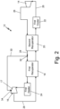
- FIG. 2 is a schematic diagram illustrating a first embodiment of closed-loop Brayton cycle system 12 including turbine blade cooling features.
- Closed-loop Brayton cycle system 12 will hereinafter be referred to as "system 12".
- System 12 includes first compressor 14, first turbine 16, first recuperator 18, second recuperator 20, first cooler 22, first heater 24, closed-loop flow channel 26, conduit 28, and bleed channel 30.
- Bleed channel 30 includes bleed inlet 32 and bleed outlet 34.
- First turbine 16 includes a plurality of turbine blades 17 positioned within first turbine 16, such that the plurality of turbine blades 17 extend circumferentially around an axis of first turbine 16 (not explicitly depicted). The plurality of turbine blades 17 are configured to extract energy from the high temperature, high pressure working fluid flowing through system 12.
- the plurality of turbine blades 17 are constructed from a nickel-chromium-based superalloy material to withstand the high temperatures of the working fluid flowing past the plurality of turbine blades 17 during operation of system 12. Further, each of the plurality of turbine blades 17 include internal cooling features to allow the plurality of turbine blades 17 to withstand the high temperatures of the working fluid flowing past the plurality of turbine blades 17 during operation of system 12.
- the internal cooling features can be one or more of internal cooling passages, raised internal turbulators or trip strips, and film cooling holes, among other options.
- the internal cooling features may be analogous to those commonly used for aircraft gas turbine engine turbine blades.
- First compressor 14 is a component of system 12 that is fluidly coupled to closed-loop flow channel 26 of system 12.
- First compressor 14 is configured to receive a working fluid, compress the working fluid to increase the pressure and temperature of the working fluid, and then flow the compressed working fluid into closed-loop flow channel 26.
- First turbine 16 is a component of system 12 that is fluidly coupled to closed-loop flow channel 26 of system 12.
- First turbine 16 is configured to receive a high temperature, high pressure working fluid, extract energy from the high temperature, high pressure working fluid, and then flow the working fluid back into closed-loop flow channel 26.
- First compressor 14 and first turbine 16 are fluidly coupled through closed-loop flow channel 26, such that the working fluid can flow through system 12 from one component to the other.
- First recuperator 18 and second recuperator 20 are components of system 12 that are fluidly coupled to closed-loop flow channel 26 of system 12.
- First recuperator 18 and second recuperator 20 are both positioned between first compressor 14 and first turbine 16.
- first recuperator 18 and second recuperator 20 are both fluidly coupled to first compressor 14 and first turbine 16 through closed-loop flow channel 26.
- closed-loop flow channel 26 creates a flow path to each of first turbine 16, first recuperator 18, second recuperator 20, and first compressor 14, allowing the working fluid to continuously recirculate through system 12 during operation of system 12.
- first recuperator 18 is fluidly coupled through conduit 28 to second recuperator 20, allowing the working fluid to flow from second recuperator 20 through conduit 28 to first recuperator 18.
- First recuperator 18 and second recuperator 20 are configured to extract heat from the working fluid after the working fluid exits first turbine 16, and first recuperator 18 and second recuperator 20 are configured to transfer the extracted heat to the working fluid after the working fluid exits first compressor 14.
- first recuperator 18 and second recuperator 20 are heat exchangers that are configured to transfer heat from one portion of system 12 to another portion of system 12, discussed below.
- first recuperator 18 and second recuperator 20 are positioned in series, such that first recuperator 18 and second recuperator 20 are connected end-to-end through conduit 28 to form a path for the working fluid that is directed to the first heater 24 and first turbine 16 to flow from second recuperator 20 to first recuperator 18.
- Closed-loop flow channel 26 and conduit 28 can be any fluid tight channel, passage, or conduit that allows the working fluid to flow through system 12.
- system 12 also includes first cooler 22 and first heater 24.
- First cooler 22 can be positioned between and fluidly coupled through closed-loop flow channel 26 to both second recuperator 20 and first compressor 14, such that the working fluid flowing out of second recuperator 20 can flow through first cooler 22 before flowing into first compressor 14.
- First cooler 22 can be a heat exchanger or any other device capable of reducing the temperature of the working fluid as the working fluid flows through first cooler 22.
- First heater 24 can be positioned between and fluidly coupled through closed-loop flow channel 26 to both first recuperator 18 and first turbine 16, such that the working fluid flowing out from first recuperator 18 can flow through first heater 24 before flowing into first turbine 16.
- First heater 24 can be one or more of an external combustor system, combustion chamber, heat exchanger, solar energy device, or any other device capable of increasing the temperature of the working fluid as the working fluid flows through first heater 24.
- system 12 may not include first cooler 22 and/or first heater 24.
- System 12 further includes bleed channel 30 including bleed inlet 32 and bleed outlet 34.
- Bleed channel 30 can be any fluid tight channel, passage, and/or conduit that allows the working fluid to flow through bleed channel 30.
- Bleed inlet 32 of bleed channel 30 is fluidly coupled to conduit 28 at a location between first recuperator 18 and second recuperator 20.
- bleed inlet 32 can be fluidly coupled to conduit 28 at approximately a mid-point of a length of conduit 28 extending between and fluidly connecting second recuperator 20 to first recuperator 18.
- Bleed outlet 34 of bleed channel 30 is fluidly coupled to first turbine 16, and more specifically fluidly coupled to each of the plurality of turbine blades 17 of first turbine 16.
- Bleed channel 30 extends between bleed inlet 32 and bleed outlet 34, providing a flow path between bleed inlet 32 and bleed outlet 34, and therefore a flow path between conduit 28 and first turbine 16.
- Bleed channel 30 is configured to direct a bleed stream of working fluid from conduit 28, through bleed inlet 32, bleed channel 30, and bleed outlet 34, and into each of the plurality of turbine blades 17 of turbine 16. More specifically, bleed channel 30 is configured to direct the bleed stream of working fluid from conduit 28, through bleed channel 30, and into the internal cooling features of each of the plurality of turbine blades 17 to reduce the temperature of each of the plurality of turbine blades 17 when system 12 is operating, discussed further below.
- System 12 is configured to flow the working fluid through system 12 such that the working fluid continuously recirculates through system 12 during operation.
- the working fluid can be a supercritical carbon dioxide (sCO 2 ).
- Supercritical carbon dioxide is a fluid state of carbon dioxide (CO 2 ), where it is held at or above its critical temperature and critical pressure. Carbon dioxide usually behaves as a gas in air at standard temperature and pressure, or as a solid called dry ice when frozen. If the temperature and pressure are both increased from standard temperature and pressure to be at or above the critical point for carbon dioxide, it can adopt properties midway between a gas and a liquid. At this state, supercritical carbon dioxide can be used efficiently within a closed-loop Brayton cycle system. Further, supercritical carbon dioxide may accommodate a large temperature difference whilst remaining in a supercritical state, facilitating design and coupling of turbomachine components.
- Supercritical CO 2 in an example Brayton cycle operating at cycle temperatures of interest also undergoes an extreme density change throughout the cycle, becoming very dense immediately before compression and much less dense before expansion. These density changes are advantageous in that power required to compress is reduced and power obtained through expansion is increased. Further, the low density of CO 2 just before expansion is still greater than air at a corresponding point in an open-loop air Brayton cycle, enabling the size of most system components, such as turbines, compressors, and recuperators, to be reduced compared to corresponding air-breathing components, leading to a smaller plant footprint and possibly lower capital costs.
- Supercritical carbon dioxide is also generally considered an ideal working fluid because it is non-explosive, non-flammable, non-toxic, and inexpensive. As such, using supercritical carbon dioxide as the working fluid for system 12 can provide many advantages that can lead to highly efficient power generation systems.
- the working fluid flowing through closed-loop flow channel 26 flows into first compressor 14, where the working fluid is compressed to achieve a higher temperature and higher pressure working fluid.
- the working fluid flows out first compressor 14, through closed-loop flow channel 26, and into second recuperator 20 where heat is added to the compressed working fluid.
- second recuperator 20 is configured to extract heat from the working fluid after the working fluid exits first turbine 16, and second recuperator 20 is configured to transfer the extracted heat to the working fluid after the working fluid exits first compressor 14.
- second recuperator 20 is configured to heat the working fluid exiting second recuperator 20 to a temperature ranging between 50°C and 250°C when system 12 is operating.
- the working fluid flows out of second recuperator 20 and into conduit 28, which fluidly connects second recuperator 20 to first recuperator 18.
- the working fluid (CO 2 ) will exist in a liquid or two-phase state for part of the cycle, such as, but not limited to, the flow leg between second recuperator 20 and first cooler 22, and/or the flow leg after first cooler 22 and compressor 14.
- a first portion of the working fluid flowing through conduit 28 enters bleed inlet 32 of bleed channel 30, while a second portion of the working fluid flowing through conduit 28 enters first recuperator 18.
- the first portion of the working fluid enters bleed inlet 32, flows through bleed channel 30 to bleed outlet 34, and then flows through bleed outlet 34 into the internal cooling features of each of the plurality of turbine blades 17 of first turbine 16.
- the first portion of the working fluid flowing through bleed channel 30 and bleed outlet 34 into the internal cooling features of the plurality of turbine blades 17 is at a temperature ranging between 50°C and 250°C when system 12 is operating. As such, the first portion of the working fluid is configured to cool and reduce the temperature of each of the plurality of turbine blades 17 during operation of system 12.
- the first portion of the working fluid flowing into each of the plurality of turbine blades 17 flows through the internal cooling features within an interior of each of the plurality of turbine blades 17, absorbing heat from the each of the plurality of turbine blades 17 to decrease the temperature of each of the plurality of turbine blades 17 during operation of system 12.
- the first portion of the working fluid then exits and combines with the second portion of the working fluid being expanded within first turbine 16.
- first recuperator 18 The second portion of the working fluid flowing through conduit 28 enters first recuperator 18 where heat is added to the compressed and heated working fluid.
- first recuperator 18 is configured to extract heat from the working fluid after the working fluid exits first turbine 16, and first recuperator 18 is configured to transfer the extracted heat to the working fluid after the working fluid exits second recuperator 20 and enter first recuperator 18.
- first recuperator 18 is configured to heat the working fluid exiting first recuperator 18 to a temperature ranging between 750°C and 1250°C when system 12 is operating.
- the working fluid flows out first recuperator 18, into closed-loop flow channel 26, and then into first heater 24.
- the working fluid flows through first heater 24, where additional heat is added to the compressed and heated working fluid to further increase the temperature of the working fluid before entering first turbine 16.
- first heater 24 is configured to heat the working fluid to a temperature up to 1500°C when system 12 is operating. As discussed, the higher the temperature of the working fluid entering first turbine 16 of system 12, the more efficiently system 12 performs.
- the working fluid entering first turbine 16 can be at temperatures up to 1500°C and the bleed stream entering the internal cooling features of each of the plurality of turbine blades 17 can be at a temperature ranging between 50°C and 250°C. Therefore, the bleed stream can enter first turbine 16 at a first temperature and the working fluid can enter first turbine 16 at a second temperature, significantly higher than the first temperature.
- the blead stream is configured to cool each of the plurality of turbine blades 17 by removing heat added to first turbine 16 by the extremely high temperature working fluid flowing through first turbine 16, during operation of system 12. It is to be understood that the temperature ranges described are not to be construed as limiting and describe only certain operating scenarios. The actual temperature ranges during operation of system 12 may vary depending on a multitude of factors.
- the heated working fluid flows through and is expanded within first turbine 16, such that power is extracted from the working fluid to be used by a generator or other system.
- the expanded working fluid continues by flowing through first recuperator 18 and second recuperator 20, where heat is extracted from the working fluid after exiting first turbine 16. At least some of the heat that is extracted from the working fluid is subsequently transferred to the working fluid exiting first compressor 14 and flowing toward first turbine 16, to increase the temperature of the flowing working fluid.
- the working fluid continuously recirculates through system 12 to produce energy that can be used by an engine or other system. More specifically, the working fluid is continuously heated and cooled during a continuous recirculating cycle to efficiently create power that can be used to drive generators or other systems.
- System 12 including a split recuperator (first recuperator 18 and second recuperator 20) and supercritical carbon dioxide as the working fluid allows for high efficiency to be achieved through high turbine input temperatures, as compared to previous fluid power cycles.
- the efficiency of closed-loop Brayton cycle system 12 is equal to or greater than 50%, with the efficiency calculated by dividing the power output (kW) of system 12 by the heat input (kW) supplied to system 12 through the first heater 24.
- system 12 including bleed channel 30 and internal cooling features within each of the plurality of turbine blades 17, allows a portion of the working fluid to be used to reduce the temperature of each of the plurality of turbine blades 17 during operation of system 12, preventing melting or damage to turbine blades 17 during operation of system 12.
- Previous fluid power cycles without bleed channels and turbine blades with internal cooling features are limited in the efficiencies that can be achieved by the material properties of the turbine section.
- the temperature of the working fluid flowing into the turbine section can only be raised to a maximum temperature limit before the high temperatures of the working fluid will begin melting or damaging the turbine section.
- System 12 of the present application allows the working fluid to enter first turbine 16 at temperatures above the melting point of the components of first turbine 16, and bleed channel 30 and the internal cooling features reduce the temperature of the components of first turbine 16 to prevent melting or damage to first turbine 16.
- the increased temperature of the working fluid entering first turbine 16 results in higher power cycle efficiencies than could previously be achieved.
- System 12 provides a solution for achieving greater power generation efficiencies to reduce fuel cost and for complying with increasingly strict emissions regulations, among other advantages not specifically described.
- FIG. 3 is a schematic diagram illustrating a second embodiment of closed-loop Brayton cycle system 12A with turbine blade cooling.
- System 12A shown in FIG. 3 is substantially similar to system 12 of FIG. 2 , and therefore only the differences between system 12 and system 12A will be discussed. Further, it is to be understood that the description regarding system 12 shown in FIG. 2 equally applies to system 12A shown in FIG. 3 , unless discussed otherwise.
- System 12A includes first compressor 14A, first turbine 16A, second turbine 36A, first recuperator 18A, second recuperator 20A, first cooler 22A, first heater 24A, closed-loop flow channel 26A, conduit 28A, and bleed channel 30A.
- Bleed channel 30A includes bleed inlet 32A and bleed outlets 34A and 34A'.
- system 12A of FIG. 3 includes the additional components of second turbine 36A and bleed outlet 34A', with an extra section of bleed channel 30A connecting to bleed outlet 34A'.
- Second turbine 36A is positioned between and fluidly coupled to both first turbine 16A and first recuperator 18A through closed-loop flow channel 26A.
- Bleed outlet 34A' is fluidly coupled to second turbine 36A, providing a flow path for the cooling bleed stream of the working fluid to flow to second turbine 36A.
- system 12A of FIG. 3 operates the same as system 12 of FIG. 2 , except after the expanded working fluid exits first turbine 16A, the working fluid enters and is expanded through second turbine 36A to further extract energy from the working fluid. After the working fluid exits second turbine 36A, system 12A of FIG. 3 operates the same as system 12 of FIG. 2 .
- system 12A includes an extra section of bleed channel 30A fluidly coupled to bleed outlet 34A'. Bleed outlet 34A' of bleed channel 30A is fluidly coupled to second turbine 36A, and more specifically fluidly coupled to each of the plurality of turbine blades 37A of second turbine 36A (not explicitly depicted).
- Bleed channel 30A extends between bleed inlet 32A and bleed outlet 34A', providing a flow path between bleed inlet 32A and bleed outlet 34A', and therefore a flow path between conduit 28A and second turbine 36A.
- Bleed channel 30A is configured to direct a bleed stream of working fluid from conduit 28A, through bleed inlet 32A, bleed channel 30A, and bleed outlet 34A', and into each of the plurality of turbine blades 37A of second turbine 36A.
- bleed channel 30A is configured to direct the bleed stream of working fluid from conduit 28A, through bleed channel 30A, and into the internal cooling features of each of the plurality of turbine blades 37A to reduce the temperature of each of the plurality of turbine blades 37A of second turbine 36A when system 12A is operating.
- system 12A shown in FIG. 3 is another example of a closed-loop Brayton cycle system with turbine blade cooling, to achieve greater efficiencies than could previously be achieved.
- bleed channel 30A is fluidly coupled to first turbine 16A and second turbine 36A, and bleed channel 30A is configured to direct the bleed stream of the working fluid flowing through bleed channel 30A into internal cooling features within both first turbine 16A and second turbine 36A when closed-loop Brayton cycle system 12A is operating.
- System 12A of FIG. 3 provides a solution for achieving greater power generation efficiencies to comply with increasingly strict emissions regulations, among other advantages not specifically described.
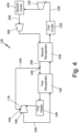
- FIG. 4 is a schematic diagram illustrating a third embodiment of closed-loop Brayton cycle system 12B with turbine blade cooling.
- System 12B shown in FIG. 4 is substantially similar to system 12 of FIG. 2 , and therefore only the differences between system 12 and system 12B will be discussed. Further, it is to be understood that the description regarding system 12 shown in FIG. 2 equally applies to system 12B shown in FIG. 4 , unless discussed otherwise.
- System 12B includes first compressor 14B, second compressor 38B, first turbine 16B, first recuperator 18B, second recuperator 20B, first cooler 22B, second cooler 40B, first heater 24B, closed-loop flow channel 26B, conduit 28B, and bleed channel 30B. The difference between system 12 of FIG. 2 and system 12B of FIG.
- system 12B of FIG. 4 includes the additional components of second compressor 38B and second cooler 40B.
- Second cooler 40B is positioned between and fluidly coupled to both first compressor 14B and second compressor 38B through closed-loop flow channel 26B.
- second compressor 38B is positioned between and fluidly coupled to both second cooler 40B and second recuperator 20B through closed-loop flow channel 26B.
- system 12B of FIG. 4 operates the same as system 12 of FIG. 2 , except after the compressed working fluid exits first compressor 14B, the working fluid enters and is cooled within second cooler 40B to further reduced the temperature of the working fluid. After the working fluid exits second cooler 40B, the cooled working fluid enters second compressor 38B where the working fluid is again compressed to increase the pressure of the working fluid. After, the working fluid exits second compressor 38B, system 12B operates essentially the same as system 12 of FIG. 2 , to avoid redundancy the operation will not be discussed again in detail.
- System 12B shown in FIG. 4 is another example of a closed-loop Brayton cycle system with turbine blade cooling, to achieve greater efficiencies than could previously be achieved.
- system 12B includes second cooler 40B, which reduces the temperature of the fluid, thereby reducing the power required to perform compression in compressor 38B.
- System 12B of FIG. 4 provides a solution for achieving greater power generation efficiencies to comply with increasingly strict emissions regulations, among other advantages not specifically described.
- FIG. 5 is a schematic diagram illustrating a fourth embodiment of closed-loop Brayton cycle system 12C with turbine blade cooling.
- System 12C shown in FIG. 5 is similar to system 12 of FIG. 2 , and therefore only the differences between system 12 and system 12C will be discussed. Further, it is to be understood that the description regarding system 12 shown in FIG. 2 equally applies to system 12C shown in FIG. 5 , unless discussed otherwise.
- System 12C includes first compressor 14C, second compressor 38C, first turbine 16C, second turbine 36C, first recuperator 18C, second recuperator 20C, third recuperator 42C, first cooler 22C, second cooler 40C, first heater 24C, second heater 44C, closed-loop flow channel 26C, conduit 28C, bleed channel 30C, and cooling channel 46C.
- the main difference between system 12C of FIG. 5 and system 12 of FIG. 2 is that system 12C of FIG. 5 includes cooling channel 46C and third recuperator 42C, discussed further below.
- the working fluid flowing through closed-loop flow channel 26C flows into and through first cooler 22C, where the temperature of the working fluid is reduced.
- the cooled working fluid flows into first compressor 14C, where the working fluid is compressed to increase the pressure of the working fluid.
- the working fluid flows out first compressor 14C, through closed-loop flow channel 26C, and into second cooler 40C where the temperature of the working fluid is further reduced.
- the cooled working fluid flows into second compressor 38C, where the working fluid is again compressed to further increase the pressure of the working fluid.
- the working fluid flows out second compressor 38C, through closed-loop flow channel 26C, and into second recuperator 20C where heat is added to the compressed working fluid.
- the working fluid flows out second recuperator 20C and into conduit 28C, which fluidly connects second recuperator 20C to first recuperator 18C.
- a first portion of the working fluid flowing through conduit 28C enters bleed inlet 32C of bleed channel 30C, while a second portion of the working fluid flowing through conduit 28C enters first recuperator 18C.
- the first portion of the working fluid enters bleed inlet 32C, flows through bleed channel 30C to bleed outlet 34C, and then flows through bleed outlet 34C into the internal cooling features of each of the plurality of turbine blades 17C of first turbine 16C.
- the first portion of the working fluid is configured to cool and reduce the temperature of each of the plurality of turbine blades during operation of the system.
- the second portion of the working fluid flowing through conduit 28C enters first recuperator 18C where heat is added to the compressed and heated working fluid.
- the working fluid flows out first recuperator 18C, into closed-loop flow channel 26C, and then into first heater 24C.
- the working fluid flows through first heater 24C, where additional heat is added to the compressed and heated working fluid to further increase the temperature of the working fluid before entering first turbine 16C.
- the working fluid flows out first heater 24C and into first turbine 16C where it is expanded, such that power is extracted from the working fluid to drive a generator or other system.
- the expanded working fluid continues by flowing through second heater 44C, where additional heat is added to the working fluid to further increase the temperature of the working fluid before entering second turbine 36C.
- the working fluid flows out second heater 44C and into second turbine 36C where it is again expanded, such that further power is extracted from the working fluid to drive a generator or other system.
- the working fluid continues by flowing through first recuperator 18C and second recuperator 20C, where heat is extracted from the working fluid after exiting second turbine 36C. At least some of the heat that is extracted from the working fluid is subsequently transferred to the working fluid exiting second compressor 38C and flowing toward first turbine 16C, to increase the temperature of the flowing working fluid.
- Cooling channel 46C can be any fluid tight channel, passage, or conduit that allows the working fluid to flow from a location downstream of first compressor 14C to second turbine 36C. As such, cooling channel 46C is fluidly coupled to closed-loop cooling channel 46C at a location between first compressor 14C and second cooler 40C. Further, cooling channel 46C extends from closed-loop cooling channel 46C, through third recuperator 42C, and to second turbine 36C.
- a portion of the cooled and compressed working fluid flowing out from first compressor 14C is directed through cooling channel 46C and to third recuperator 42C.
- Third recuperator 42C transfers heat from the working fluid exiting first recuperator 18C to the working fluid flowing through cooling channel 46C to increase the temperature of the working fluid.
- the working fluid flows out from third recuperator 42C and into second turbine 36C to cool components of second turbine 36C. More specifically, the working fluid flows into internal cooling features of the plurality of turbine blades 37C within second turbine 36C to remove heat from second turbine 36C.
- System 12C shown in FIG. 5 is another example of a closed-loop Brayton cycle system with turbine blade cooling, to achieve greater efficiencies than could previously be achieved.
- system 12C includes cooling channel 46C and third recuperator 42C configured to flow the working fluid to second turbine 36C at an efficient cooling pressure, allowing for greater overall efficiency of the system to be achieved.
- System 12C of FIG. 4 provides another solution for achieving greater power generation efficiencies to comply with increasingly strict emissions regulations, among other advantages not specifically described.
- a closed-loop Brayton cycle system comprising: a first compressor; a first turbine comprising a plurality of turbine blades, the first turbine fluidly coupled to the first compressor, wherein each of the plurality of turbine blades include internal cooling features; a first recuperator and a second recuperator positioned between the first compressor and the first turbine, wherein the first recuperator and the second recuperator are fluidly coupled to the first compressor and the first turbine, and wherein the first recuperator is fluidly coupled through a conduit to the second recuperator; and a bleed channel comprising a bleed inlet and a bleed outlet, wherein the bleed inlet is fluidly coupled to the conduit at a location between the first recuperator and the second recuperator, and wherein the bleed outlet is fluidly coupled to the plurality of turbine blades to direct a bleed stream of a working fluid flowing through the bleed channel into the internal cooling features of the plurality of turbine blades when the closed-loop Brayton cycle system is operating; wherein the closed-loop Brayton cycle system is configured to flow
- the closed-loop Brayton cycle system of the preceding paragraph can optionally include, additionally and/or alternatively, any one or more of the following features, configurations and/or additional components:
- the working fluid is a supercritical carbon dioxide (CO2).
- the first recuperator and the second recuperator are positioned in series, such that the first recuperator and the second recuperator are connected end-to-end, forming a path for the working fluid to flow.
- the first recuperator and the second recuperator are configured to extract heat from the working fluid after the working fluid exits the first turbine; and the first recuperator and the second recuperator are configured to transfer the extracted heat to the working fluid after the working fluid exits the first compressor.
- the second recuperator is configured to heat the working fluid exiting the first compressor prior to entering the bleed inlet of the bleed channel to a temperature ranging between 50°C and 250°C when the closed-loop Brayton cycle system is operating; the bleed channel and bleed outlet are configured to flow the working fluid into the internal cooling features of the plurality of turbine blades at a temperature ranging between 50°C and 250°C when the closed-loop Brayton cycle system is operating; and the first recuperator is configured to heat the working fluid exiting the second recuperator prior to entering the first turbine to a temperature ranging between 750°C and 1250°C when the closed-loop Brayton cycle system is operating.
- the conduit is configured to flow a first portion of the working fluid exiting the second recuperator into the bleed inlet of the bleed channel and a second portion of the working fluid exiting the second recuperator through the first recuperator and into the first turbine when the closed-loop Brayton cycle system is operating.
- the bleed channel is configured to flow the first portion of the working fluid through the bleed channel to the bleed outlet; and the bleed outlet is configured to flow the first portion of the working fluid through the bleed outlet and into the internal cooling features of the plurality of turbine blades when the closed-loop Brayton cycle system is operating.
- the first portion of the working fluid flowing into the plurality of turbine blades flows through the internal cooling features within an interior of each of the plurality of turbine blades, absorbing heat from the each of the plurality of turbine blades to decrease the temperature of each of the plurality of turbine blades.
- the closed-loop Brayton cycle system is configured to flow the working fluid through a closed-loop system when the closed-loop Brayton cycle system is operating, such that the working fluid continuously recirculates through the closed-loop system during operation of the closed-loop Brayton cycle system.
- a first heater and a first cooler wherein the first heater is positioned between and fluidly coupled to the first recuperator and the first turbine, and wherein the first cooler is positioned between and fluidly coupled to the second recuperator and the first compressor.
- a third recuperator wherein the second recuperator and the third recuperator are positioned in a parallel configuration.
- the bleed channel is fluidly coupled to the first turbine and a second turbine, and wherein the bleed channel is configured to direct the bleed stream of the working fluid flowing through the bleed channel into internal cooling features within both the first turbine and the second turbine when the closed-loop Brayton cycle system is operating.
- a method of operating a closed-loop Brayton cycle system comprising: flowing a working fluid from a first compressor to and through a second recuperator; flowing the working fluid from the second recuperator into a conduit positioned between and fluidly coupling the second recuperator to a first recuperator; directing a first portion of the working fluid through a bleed inlet of a bleed channel and into the bleed channel; directing a second portion of the working fluid through the first recuperator and into a first turbine; and flowing the first portion of the working fluid through the bleed channel and out through a bleed outlet fluidly coupled to a plurality of turbine blades positioned within the first turbine; wherein the first portion of the working fluid flowing into the plurality of turbine blades decreases the temperature of the plurality of turbine blades during operation of the closed-loop Brayton cycle system.
- the method of the preceding paragraph can optionally include, additionally and/or alternatively, any one or more of the following features, configurations and/or additional components:
- the first recuperator and the second recuperator are positioned in series, such that the first recuperator and the second recuperator are connected end-to-end, forming a path for the working fluid to flow.
- the working fluid is a supercritical carbon dioxide (CO2).
- the working fluid flowing through the second recuperator and entering the bleed inlet of the bleed channel ranges in temperature between 50°C and 250°C; the working fluid flowing through the bleed outlet of the bleed channel into the plurality of turbine blades ranges in temperature between 50°C and 250°C; and the working fluid flowing through the first recuperator and entering the first turbine ranges in temperature between 750°C and 1250°C.
Landscapes
- Engineering & Computer Science (AREA)
- Chemical & Material Sciences (AREA)
- Combustion & Propulsion (AREA)
- Mechanical Engineering (AREA)
- General Engineering & Computer Science (AREA)
- Physics & Mathematics (AREA)
- Life Sciences & Earth Sciences (AREA)
- High Energy & Nuclear Physics (AREA)
- Sustainable Development (AREA)
- Sustainable Energy (AREA)
- Chemical Kinetics & Catalysis (AREA)
- Engine Equipment That Uses Special Cycles (AREA)
Abstract
Description
- This invention was made with government support under Contract No. DE-EE0009138, Sub-Contract No. 828 awarded by The Department of Energy. The government has certain rights in the invention.
- The present invention relates to closed-loop Brayton cycle systems for power generation and, more particularly, to a closed-loop Brayton cycle system with turbine blade cooling.
- Improvements in power generation efficiencies are needed to comply with increasingly strict emissions regulations. Supercritical carbon dioxide cycles have the potential to enable high efficiency power generation at low capital costs. Further, supercritical carbon dioxide cycles have the potential to replace Rankine power generation cycle systems with smaller hardware in a more efficient thermodynamic cycle. Thermodynamic efficiency of fluid power cycles increases as the heat input temperature directly before turbine expansion increases. As such, supercritical carbon dioxide technologies enabling the requisite high temperatures can be used to achieve the desired high efficiencies, but the usefulness of supercritical carbon dioxide technologies is limited by the lack of turbine materials which can withstand continuous exposure to the required high temperatures.
- According to one aspect of the disclosure, a closed-loop Brayton cycle system is disclosed. The closed-loop Brayton cycle system includes a first compressor and a first turbine including a plurality of turbine blades, the first turbine is fluidly coupled to the first compressor. Further, each of the plurality of turbine blades include internal cooling features. The system also includes a first recuperator and a second recuperator positioned between the first compressor and the first turbine. The first recuperator and the second recuperator are fluidly coupled to the first compressor and the first turbine, and the first recuperator is fluidly coupled through a conduit to the second recuperator. Further, the system includes a bleed channel including a bleed inlet and a bleed outlet. The bleed inlet is fluidly coupled to the conduit at a location between the first recuperator and the second recuperator, and the bleed outlet is fluidly coupled to the plurality of turbine blades to direct a bleed stream of a working fluid flowing through the bleed channel into the internal cooling features of the plurality of turbine blades when the closed-loop Brayton cycle system is operating. The closed-loop Brayton cycle system is configured to flow the working fluid through the closed-loop Brayton cycle system when in operation.
- According to another aspect of the disclosure, a method of operating a closed-loop Brayton cycle system is disclosed. The method includes: flowing a working fluid from a first compressor to and through a second recuperator; flowing the working fluid from the second recuperator into a conduit positioned between and fluidly coupling the second recuperator to a first recuperator; directing a first portion of the working fluid through a bleed inlet of a bleed channel and into the bleed channel; directing a second portion of the working fluid through the first recuperator and into a first turbine; and flowing the first portion of the working fluid through the bleed channel and out through a bleed outlet fluidly coupled to a plurality of turbine blades positioned within the first turbine. The first portion of the working fluid flowing into the plurality of turbine blades decreases the temperature of the plurality of turbine blades during operation of the closed-loop Brayton cycle system.
-
-
FIG. 1 is a schematic diagram illustrating a prior art closed-loop Brayton cycle system. -
FIG. 2 is a schematic diagram illustrating a first embodiment of a closed-loop Brayton cycle system. -
FIG. 3 is a schematic diagram illustrating a second embodiment of a closed-loop Brayton cycle system. -
FIG. 4 is a schematic diagram illustrating a third embodiment of a closed-loop Brayton cycle system. -
FIG. 5 is a schematic diagram illustrating a fourth embodiment of a closed-loop Brayton cycle system. -
FIG. 1 is a schematic diagram illustrating a prior art closed-loop Brayton cycle system. The Brayton cycle is a thermodynamic cycle that describes the conversion of heat to power for the system of interest. A Brayton cycle system is used to extract energy from a flowing working fluid to generate usable work which can be used to power many different vehicles or other systems. A closed-loop Brayton cycle system is a highly efficient power cycle that recirculates the working fluid instead of expelling the working fluid as with an open or traditional air-breathing Brayton cycle system. As shown inFIG. 1 , the prior art closed-loop Braytoncycle system 10 includescompressor 10A,turbine 10B,recuperator 10C,cooler 10D, andheater 10E. In operation, a working fluid flows through each component and is recirculated withinsystem 10 to generate usable work which can be used to power many different vehicles or other systems. - More specifically, in operation, a working fluid flowing through the prior art closed-loop Brayton
cycle system 10 flows throughcompressor 10A, where the working fluid is compressed to achieve a higher temperature and higher pressure. Power to operatecompressor 10A is input through a first shaft (not shown) and may come from any available mechanical source. The working fluid flows throughrecuperator 10C, where heat is added to the compressed working fluid. Then the working fluid flows throughheater 10E, where additional heat is added to the compressed and heated working fluid to further increase the temperature of the working fluid before it entersturbine 10B. The working fluid flows through and is expanded withinturbine 10B, such that energy or work is extracted from the working fluid. Power is extracted fromturbine 10B through a second shaft (not shown) and may use used for any useful purpose, including topower compressor 10A, generate electricity, or any other useful purpose. The working fluid continues by flowing throughrecuperator 10C, where heat is extracted from the working fluid after exitingturbine 10B. At least some of the heat that is extracted from the working fluid is subsequently transferred to the workingfluid exiting compressor 10A and flowing towardsturbine 10B, to increase the temperature of the flowing working fluid. The working fluid continuously recirculates through the prior art closed-loop Braytoncycle system 10 and the working fluid is heated and cooled to create work that can be used to power engines or other systems. - According to the laws of thermodynamics, thermodynamic efficiency of fluid power cycles increases as the input temperature of the working fluid entering the turbine increases. In other words, the higher the temperature of the working fluid entering the turbine section of the system, the more efficient the fluid power cycle. Therefore, it is desirable to have high temperature working fluids entering the turbine section of the system, while also preventing melting or damage to components of the turbine section. Prior art closed-loop Brayton cycle systems, as shown in
FIG. 1 , are limited in the efficiencies that can be achieved by the material properties of the turbine section. The temperature of the working fluid flowing into the turbine section can only be raised to a maximum temperature limit before the high temperatures of the working fluid will begin melting or damaging the turbine section. As such, a closed-loop Brayton cycle system that can withstand extreme temperatures is required to achieve higher efficiency fluid power cycle systems. -
FIG. 2 is a schematic diagram illustrating a first embodiment of closed-loop Braytoncycle system 12 including turbine blade cooling features. Closed-loop Braytoncycle system 12 will hereinafter be referred to as "system 12".System 12 includesfirst compressor 14,first turbine 16,first recuperator 18,second recuperator 20,first cooler 22,first heater 24, closed-loop flow channel 26,conduit 28, and bleedchannel 30. Bleedchannel 30 includes bleedinlet 32 and bleedoutlet 34.First turbine 16 includes a plurality ofturbine blades 17 positioned withinfirst turbine 16, such that the plurality ofturbine blades 17 extend circumferentially around an axis of first turbine 16 (not explicitly depicted). The plurality ofturbine blades 17 are configured to extract energy from the high temperature, high pressure working fluid flowing throughsystem 12. In some examples, the plurality ofturbine blades 17 are constructed from a nickel-chromium-based superalloy material to withstand the high temperatures of the working fluid flowing past the plurality ofturbine blades 17 during operation ofsystem 12. Further, each of the plurality ofturbine blades 17 include internal cooling features to allow the plurality ofturbine blades 17 to withstand the high temperatures of the working fluid flowing past the plurality ofturbine blades 17 during operation ofsystem 12. The internal cooling features can be one or more of internal cooling passages, raised internal turbulators or trip strips, and film cooling holes, among other options. For example, the internal cooling features may be analogous to those commonly used for aircraft gas turbine engine turbine blades. -
First compressor 14 is a component ofsystem 12 that is fluidly coupled to closed-loop flow channel 26 ofsystem 12.First compressor 14 is configured to receive a working fluid, compress the working fluid to increase the pressure and temperature of the working fluid, and then flow the compressed working fluid into closed-loop flow channel 26.First turbine 16 is a component ofsystem 12 that is fluidly coupled to closed-loop flow channel 26 ofsystem 12.First turbine 16 is configured to receive a high temperature, high pressure working fluid, extract energy from the high temperature, high pressure working fluid, and then flow the working fluid back into closed-loop flow channel 26.First compressor 14 andfirst turbine 16 are fluidly coupled through closed-loop flow channel 26, such that the working fluid can flow throughsystem 12 from one component to the other. -
First recuperator 18 andsecond recuperator 20 are components ofsystem 12 that are fluidly coupled to closed-loop flow channel 26 ofsystem 12.First recuperator 18 andsecond recuperator 20 are both positioned betweenfirst compressor 14 andfirst turbine 16. Further,first recuperator 18 andsecond recuperator 20 are both fluidly coupled tofirst compressor 14 andfirst turbine 16 through closed-loop flow channel 26. As such, closed-loop flow channel 26 creates a flow path to each offirst turbine 16,first recuperator 18,second recuperator 20, andfirst compressor 14, allowing the working fluid to continuously recirculate throughsystem 12 during operation ofsystem 12. Further,first recuperator 18 is fluidly coupled throughconduit 28 tosecond recuperator 20, allowing the working fluid to flow fromsecond recuperator 20 throughconduit 28 tofirst recuperator 18. -
First recuperator 18 andsecond recuperator 20 are configured to extract heat from the working fluid after the working fluid exitsfirst turbine 16, andfirst recuperator 18 andsecond recuperator 20 are configured to transfer the extracted heat to the working fluid after the working fluid exitsfirst compressor 14. As such,first recuperator 18 andsecond recuperator 20 are heat exchangers that are configured to transfer heat from one portion ofsystem 12 to another portion ofsystem 12, discussed below. As shown inFIG. 2 ,first recuperator 18 andsecond recuperator 20 are positioned in series, such thatfirst recuperator 18 andsecond recuperator 20 are connected end-to-end throughconduit 28 to form a path for the working fluid that is directed to thefirst heater 24 andfirst turbine 16 to flow fromsecond recuperator 20 tofirst recuperator 18. Closed-loop flow channel 26 andconduit 28 can be any fluid tight channel, passage, or conduit that allows the working fluid to flow throughsystem 12. - As shown in
FIG. 2 ,system 12 also includes first cooler 22 andfirst heater 24. First cooler 22 can be positioned between and fluidly coupled through closed-loop flow channel 26 to bothsecond recuperator 20 andfirst compressor 14, such that the working fluid flowing out ofsecond recuperator 20 can flow through first cooler 22 before flowing intofirst compressor 14. First cooler 22 can be a heat exchanger or any other device capable of reducing the temperature of the working fluid as the working fluid flows throughfirst cooler 22.First heater 24 can be positioned between and fluidly coupled through closed-loop flow channel 26 to bothfirst recuperator 18 andfirst turbine 16, such that the working fluid flowing out fromfirst recuperator 18 can flow throughfirst heater 24 before flowing intofirst turbine 16.First heater 24 can be one or more of an external combustor system, combustion chamber, heat exchanger, solar energy device, or any other device capable of increasing the temperature of the working fluid as the working fluid flows throughfirst heater 24. In other examples,system 12 may not include first cooler 22 and/orfirst heater 24. -
System 12 further includesbleed channel 30 includingbleed inlet 32 and bleedoutlet 34. Bleedchannel 30 can be any fluid tight channel, passage, and/or conduit that allows the working fluid to flow throughbleed channel 30. Bleedinlet 32 ofbleed channel 30 is fluidly coupled toconduit 28 at a location betweenfirst recuperator 18 andsecond recuperator 20. In some examples, bleedinlet 32 can be fluidly coupled toconduit 28 at approximately a mid-point of a length ofconduit 28 extending between and fluidly connectingsecond recuperator 20 tofirst recuperator 18.Bleed outlet 34 ofbleed channel 30 is fluidly coupled tofirst turbine 16, and more specifically fluidly coupled to each of the plurality ofturbine blades 17 offirst turbine 16. Bleedchannel 30 extends betweenbleed inlet 32 and bleedoutlet 34, providing a flow path betweenbleed inlet 32 and bleedoutlet 34, and therefore a flow path betweenconduit 28 andfirst turbine 16. Bleedchannel 30 is configured to direct a bleed stream of working fluid fromconduit 28, throughbleed inlet 32, bleedchannel 30, and bleedoutlet 34, and into each of the plurality ofturbine blades 17 ofturbine 16. More specifically, bleedchannel 30 is configured to direct the bleed stream of working fluid fromconduit 28, throughbleed channel 30, and into the internal cooling features of each of the plurality ofturbine blades 17 to reduce the temperature of each of the plurality ofturbine blades 17 whensystem 12 is operating, discussed further below. -
System 12 is configured to flow the working fluid throughsystem 12 such that the working fluid continuously recirculates throughsystem 12 during operation. In some examples, the working fluid can be a supercritical carbon dioxide (sCO2). Supercritical carbon dioxide is a fluid state of carbon dioxide (CO2), where it is held at or above its critical temperature and critical pressure. Carbon dioxide usually behaves as a gas in air at standard temperature and pressure, or as a solid called dry ice when frozen. If the temperature and pressure are both increased from standard temperature and pressure to be at or above the critical point for carbon dioxide, it can adopt properties midway between a gas and a liquid. At this state, supercritical carbon dioxide can be used efficiently within a closed-loop Brayton cycle system. Further, supercritical carbon dioxide may accommodate a large temperature difference whilst remaining in a supercritical state, facilitating design and coupling of turbomachine components. - Supercritical CO2 in an example Brayton cycle operating at cycle temperatures of interest also undergoes an extreme density change throughout the cycle, becoming very dense immediately before compression and much less dense before expansion. These density changes are advantageous in that power required to compress is reduced and power obtained through expansion is increased. Further, the low density of CO2 just before expansion is still greater than air at a corresponding point in an open-loop air Brayton cycle, enabling the size of most system components, such as turbines, compressors, and recuperators, to be reduced compared to corresponding air-breathing components, leading to a smaller plant footprint and possibly lower capital costs. Supercritical carbon dioxide is also generally considered an ideal working fluid because it is non-explosive, non-flammable, non-toxic, and inexpensive. As such, using supercritical carbon dioxide as the working fluid for
system 12 can provide many advantages that can lead to highly efficient power generation systems. - In operation, the working fluid flowing through closed-
loop flow channel 26 flows intofirst compressor 14, where the working fluid is compressed to achieve a higher temperature and higher pressure working fluid. The working fluid flows outfirst compressor 14, through closed-loop flow channel 26, and intosecond recuperator 20 where heat is added to the compressed working fluid. As discussed,second recuperator 20 is configured to extract heat from the working fluid after the working fluid exitsfirst turbine 16, andsecond recuperator 20 is configured to transfer the extracted heat to the working fluid after the working fluid exitsfirst compressor 14. In some examples,second recuperator 20 is configured to heat the working fluid exitingsecond recuperator 20 to a temperature ranging between 50°C and 250°C whensystem 12 is operating. The working fluid flows out ofsecond recuperator 20 and intoconduit 28, which fluidly connectssecond recuperator 20 tofirst recuperator 18. It should be noted that in some applications, it is possible to cool the working fluid (CO2) below the critical point before entering intocompressor 14. In such cases, the working fluid (CO2) will exist in a liquid or two-phase state for part of the cycle, such as, but not limited to, the flow leg betweensecond recuperator 20 and first cooler 22, and/or the flow leg after first cooler 22 andcompressor 14. - A first portion of the working fluid flowing through
conduit 28 entersbleed inlet 32 ofbleed channel 30, while a second portion of the working fluid flowing throughconduit 28 entersfirst recuperator 18. The first portion of the working fluid enters bleedinlet 32, flows throughbleed channel 30 to bleedoutlet 34, and then flows throughbleed outlet 34 into the internal cooling features of each of the plurality ofturbine blades 17 offirst turbine 16. The first portion of the working fluid flowing throughbleed channel 30 and bleedoutlet 34 into the internal cooling features of the plurality ofturbine blades 17 is at a temperature ranging between 50°C and 250°C whensystem 12 is operating. As such, the first portion of the working fluid is configured to cool and reduce the temperature of each of the plurality ofturbine blades 17 during operation ofsystem 12. More specifically, the first portion of the working fluid flowing into each of the plurality ofturbine blades 17 flows through the internal cooling features within an interior of each of the plurality ofturbine blades 17, absorbing heat from the each of the plurality ofturbine blades 17 to decrease the temperature of each of the plurality ofturbine blades 17 during operation ofsystem 12. The first portion of the working fluid then exits and combines with the second portion of the working fluid being expanded withinfirst turbine 16. - The second portion of the working fluid flowing through
conduit 28 entersfirst recuperator 18 where heat is added to the compressed and heated working fluid. As discussed,first recuperator 18 is configured to extract heat from the working fluid after the working fluid exitsfirst turbine 16, andfirst recuperator 18 is configured to transfer the extracted heat to the working fluid after the working fluid exitssecond recuperator 20 and enterfirst recuperator 18. In some examples,first recuperator 18 is configured to heat the working fluid exitingfirst recuperator 18 to a temperature ranging between 750°C and 1250°C whensystem 12 is operating. The working fluid flows outfirst recuperator 18, into closed-loop flow channel 26, and then intofirst heater 24. The working fluid flows throughfirst heater 24, where additional heat is added to the compressed and heated working fluid to further increase the temperature of the working fluid before enteringfirst turbine 16. In some examples,first heater 24 is configured to heat the working fluid to a temperature up to 1500°C whensystem 12 is operating. As discussed, the higher the temperature of the working fluid enteringfirst turbine 16 ofsystem 12, the more efficientlysystem 12 performs. - As seen from the above, the working fluid entering
first turbine 16 can be at temperatures up to 1500°C and the bleed stream entering the internal cooling features of each of the plurality ofturbine blades 17 can be at a temperature ranging between 50°C and 250°C. Therefore, the bleed stream can enterfirst turbine 16 at a first temperature and the working fluid can enterfirst turbine 16 at a second temperature, significantly higher than the first temperature. As such, the blead stream is configured to cool each of the plurality ofturbine blades 17 by removing heat added tofirst turbine 16 by the extremely high temperature working fluid flowing throughfirst turbine 16, during operation ofsystem 12. It is to be understood that the temperature ranges described are not to be construed as limiting and describe only certain operating scenarios. The actual temperature ranges during operation ofsystem 12 may vary depending on a multitude of factors. - The heated working fluid flows through and is expanded within
first turbine 16, such that power is extracted from the working fluid to be used by a generator or other system. The expanded working fluid continues by flowing throughfirst recuperator 18 andsecond recuperator 20, where heat is extracted from the working fluid after exitingfirst turbine 16. At least some of the heat that is extracted from the working fluid is subsequently transferred to the working fluid exitingfirst compressor 14 and flowing towardfirst turbine 16, to increase the temperature of the flowing working fluid. The working fluid continuously recirculates throughsystem 12 to produce energy that can be used by an engine or other system. More specifically, the working fluid is continuously heated and cooled during a continuous recirculating cycle to efficiently create power that can be used to drive generators or other systems. -
System 12 including a split recuperator (first recuperator 18 and second recuperator 20) and supercritical carbon dioxide as the working fluid allows for high efficiency to be achieved through high turbine input temperatures, as compared to previous fluid power cycles. In some examples, the efficiency of closed-loopBrayton cycle system 12 is equal to or greater than 50%, with the efficiency calculated by dividing the power output (kW) ofsystem 12 by the heat input (kW) supplied tosystem 12 through thefirst heater 24. Further,system 12 includingbleed channel 30 and internal cooling features within each of the plurality ofturbine blades 17, allows a portion of the working fluid to be used to reduce the temperature of each of the plurality ofturbine blades 17 during operation ofsystem 12, preventing melting or damage toturbine blades 17 during operation ofsystem 12. - Previous fluid power cycles without bleed channels and turbine blades with internal cooling features are limited in the efficiencies that can be achieved by the material properties of the turbine section. The temperature of the working fluid flowing into the turbine section can only be raised to a maximum temperature limit before the high temperatures of the working fluid will begin melting or damaging the turbine section.
System 12 of the present application allows the working fluid to enterfirst turbine 16 at temperatures above the melting point of the components offirst turbine 16, and bleedchannel 30 and the internal cooling features reduce the temperature of the components offirst turbine 16 to prevent melting or damage tofirst turbine 16. In turn, the increased temperature of the working fluid enteringfirst turbine 16 results in higher power cycle efficiencies than could previously be achieved.System 12 provides a solution for achieving greater power generation efficiencies to reduce fuel cost and for complying with increasingly strict emissions regulations, among other advantages not specifically described. -
FIG. 3 is a schematic diagram illustrating a second embodiment of closed-loopBrayton cycle system 12A with turbine blade cooling.System 12A shown inFIG. 3 is substantially similar tosystem 12 ofFIG. 2 , and therefore only the differences betweensystem 12 andsystem 12A will be discussed. Further, it is to be understood that thedescription regarding system 12 shown inFIG. 2 equally applies tosystem 12A shown inFIG. 3 , unless discussed otherwise.System 12A includesfirst compressor 14A,first turbine 16A,second turbine 36A,first recuperator 18A,second recuperator 20A, first cooler 22A,first heater 24A, closed-loop flow channel 26A,conduit 28A, and bleedchannel 30A. Bleedchannel 30A includesbleed inlet 32A and bleedoutlets system 12 ofFIG. 2 andsystem 12A ofFIG. 3 is thatsystem 12A ofFIG. 3 includes the additional components ofsecond turbine 36A and bleedoutlet 34A', with an extra section ofbleed channel 30A connecting to bleedoutlet 34A'.Second turbine 36A is positioned between and fluidly coupled to bothfirst turbine 16A andfirst recuperator 18A through closed-loop flow channel 26A. Bleedoutlet 34A' is fluidly coupled tosecond turbine 36A, providing a flow path for the cooling bleed stream of the working fluid to flow tosecond turbine 36A. - In operation,
system 12A ofFIG. 3 operates the same assystem 12 ofFIG. 2 , except after the expanded working fluid exitsfirst turbine 16A, the working fluid enters and is expanded throughsecond turbine 36A to further extract energy from the working fluid. After the working fluid exitssecond turbine 36A,system 12A ofFIG. 3 operates the same assystem 12 ofFIG. 2 . In addition,system 12A includes an extra section ofbleed channel 30A fluidly coupled to bleedoutlet 34A'. Bleedoutlet 34A' ofbleed channel 30A is fluidly coupled tosecond turbine 36A, and more specifically fluidly coupled to each of the plurality ofturbine blades 37A ofsecond turbine 36A (not explicitly depicted). Bleedchannel 30A extends betweenbleed inlet 32A and bleedoutlet 34A', providing a flow path betweenbleed inlet 32A and bleedoutlet 34A', and therefore a flow path betweenconduit 28A andsecond turbine 36A. Bleedchannel 30A is configured to direct a bleed stream of working fluid fromconduit 28A, throughbleed inlet 32A, bleedchannel 30A, and bleedoutlet 34A', and into each of the plurality ofturbine blades 37A ofsecond turbine 36A. More specifically, bleedchannel 30A is configured to direct the bleed stream of working fluid fromconduit 28A, throughbleed channel 30A, and into the internal cooling features of each of the plurality ofturbine blades 37A to reduce the temperature of each of the plurality ofturbine blades 37A ofsecond turbine 36A whensystem 12A is operating. - As such,
system 12A shown inFIG. 3 is another example of a closed-loop Brayton cycle system with turbine blade cooling, to achieve greater efficiencies than could previously be achieved. In this example, bleedchannel 30A is fluidly coupled tofirst turbine 16A andsecond turbine 36A, and bleedchannel 30A is configured to direct the bleed stream of the working fluid flowing throughbleed channel 30A into internal cooling features within bothfirst turbine 16A andsecond turbine 36A when closed-loopBrayton cycle system 12A is operating.System 12A ofFIG. 3 provides a solution for achieving greater power generation efficiencies to comply with increasingly strict emissions regulations, among other advantages not specifically described. -
FIG. 4 is a schematic diagram illustrating a third embodiment of closed-loopBrayton cycle system 12B with turbine blade cooling.System 12B shown inFIG. 4 is substantially similar tosystem 12 ofFIG. 2 , and therefore only the differences betweensystem 12 andsystem 12B will be discussed. Further, it is to be understood that thedescription regarding system 12 shown inFIG. 2 equally applies tosystem 12B shown inFIG. 4 , unless discussed otherwise.System 12B includesfirst compressor 14B,second compressor 38B,first turbine 16B,first recuperator 18B,second recuperator 20B, first cooler 22B, second cooler 40B,first heater 24B, closed-loop flow channel 26B,conduit 28B, and bleedchannel 30B. The difference betweensystem 12 ofFIG. 2 andsystem 12B ofFIG. 4 is thatsystem 12B ofFIG. 4 includes the additional components ofsecond compressor 38B and second cooler 40B. Second cooler 40B is positioned between and fluidly coupled to bothfirst compressor 14B andsecond compressor 38B through closed-loop flow channel 26B. Further,second compressor 38B is positioned between and fluidly coupled to both second cooler 40B andsecond recuperator 20B through closed-loop flow channel 26B. - In operation,
system 12B ofFIG. 4 operates the same assystem 12 ofFIG. 2 , except after the compressed working fluid exitsfirst compressor 14B, the working fluid enters and is cooled within second cooler 40B to further reduced the temperature of the working fluid. After the working fluid exits second cooler 40B, the cooled working fluid enterssecond compressor 38B where the working fluid is again compressed to increase the pressure of the working fluid. After, the working fluid exitssecond compressor 38B,system 12B operates essentially the same assystem 12 ofFIG. 2 , to avoid redundancy the operation will not be discussed again in detail.System 12B shown inFIG. 4 is another example of a closed-loop Brayton cycle system with turbine blade cooling, to achieve greater efficiencies than could previously be achieved. In this example,system 12B includes second cooler 40B, which reduces the temperature of the fluid, thereby reducing the power required to perform compression incompressor 38B.System 12B ofFIG. 4 provides a solution for achieving greater power generation efficiencies to comply with increasingly strict emissions regulations, among other advantages not specifically described. -
FIG. 5 is a schematic diagram illustrating a fourth embodiment of closed-loopBrayton cycle system 12C with turbine blade cooling.System 12C shown inFIG. 5 is similar tosystem 12 ofFIG. 2 , and therefore only the differences betweensystem 12 andsystem 12C will be discussed. Further, it is to be understood that thedescription regarding system 12 shown inFIG. 2 equally applies tosystem 12C shown inFIG. 5 , unless discussed otherwise.System 12C includesfirst compressor 14C,second compressor 38C,first turbine 16C,second turbine 36C,first recuperator 18C,second recuperator 20C,third recuperator 42C, first cooler 22C, second cooler 40C,first heater 24C,second heater 44C, closed-loop flow channel 26C,conduit 28C, bleedchannel 30C, and coolingchannel 46C. The main difference betweensystem 12C ofFIG. 5 andsystem 12 ofFIG. 2 is thatsystem 12C ofFIG. 5 includescooling channel 46C andthird recuperator 42C, discussed further below. - In operation, the working fluid flowing through closed-
loop flow channel 26C flows into and through first cooler 22C, where the temperature of the working fluid is reduced. The cooled working fluid flows intofirst compressor 14C, where the working fluid is compressed to increase the pressure of the working fluid. The working fluid flows outfirst compressor 14C, through closed-loop flow channel 26C, and into second cooler 40C where the temperature of the working fluid is further reduced. The cooled working fluid flows intosecond compressor 38C, where the working fluid is again compressed to further increase the pressure of the working fluid. The working fluid flows outsecond compressor 38C, through closed-loop flow channel 26C, and intosecond recuperator 20C where heat is added to the compressed working fluid. The working fluid flows outsecond recuperator 20C and intoconduit 28C, which fluidly connectssecond recuperator 20C tofirst recuperator 18C. - A first portion of the working fluid flowing through
conduit 28C enters bleedinlet 32C ofbleed channel 30C, while a second portion of the working fluid flowing throughconduit 28C entersfirst recuperator 18C. The first portion of the working fluid enters bleedinlet 32C, flows throughbleed channel 30C to bleedoutlet 34C, and then flows throughbleed outlet 34C into the internal cooling features of each of the plurality ofturbine blades 17C offirst turbine 16C. As discussed regardingsystem 12 ofFIG. 2 , the first portion of the working fluid is configured to cool and reduce the temperature of each of the plurality of turbine blades during operation of the system. - The second portion of the working fluid flowing through
conduit 28C entersfirst recuperator 18C where heat is added to the compressed and heated working fluid. The working fluid flows outfirst recuperator 18C, into closed-loop flow channel 26C, and then intofirst heater 24C. The working fluid flows throughfirst heater 24C, where additional heat is added to the compressed and heated working fluid to further increase the temperature of the working fluid before enteringfirst turbine 16C. The working fluid flows outfirst heater 24C and intofirst turbine 16C where it is expanded, such that power is extracted from the working fluid to drive a generator or other system. The expanded working fluid continues by flowing throughsecond heater 44C, where additional heat is added to the working fluid to further increase the temperature of the working fluid before enteringsecond turbine 36C. The working fluid flows outsecond heater 44C and intosecond turbine 36C where it is again expanded, such that further power is extracted from the working fluid to drive a generator or other system. The working fluid continues by flowing throughfirst recuperator 18C andsecond recuperator 20C, where heat is extracted from the working fluid after exitingsecond turbine 36C. At least some of the heat that is extracted from the working fluid is subsequently transferred to the working fluid exitingsecond compressor 38C and flowing towardfirst turbine 16C, to increase the temperature of the flowing working fluid. - Some of the working fluid that flows through
first recuperator 18C is directed tothird recuperator 42C, which is positioned in a parallel configuration withsecond recuperator 20C.Third recuperator 42C is configured to extract heat from the working fluid flowing throughthird recuperator 42C and transfer the extracted heat to the working fluid flowing throughcooling channel 46C.Cooling channel 46C can be any fluid tight channel, passage, or conduit that allows the working fluid to flow from a location downstream offirst compressor 14C tosecond turbine 36C. As such,cooling channel 46C is fluidly coupled to closed-loop cooling channel 46C at a location betweenfirst compressor 14C and second cooler 40C. Further, coolingchannel 46C extends from closed-loop cooling channel 46C, throughthird recuperator 42C, and tosecond turbine 36C. - In operation, a portion of the cooled and compressed working fluid flowing out from
first compressor 14C is directed throughcooling channel 46C and tothird recuperator 42C.Third recuperator 42C transfers heat from the working fluid exitingfirst recuperator 18C to the working fluid flowing throughcooling channel 46C to increase the temperature of the working fluid. The working fluid flows out fromthird recuperator 42C and intosecond turbine 36C to cool components ofsecond turbine 36C. More specifically, the working fluid flows into internal cooling features of the plurality ofturbine blades 37C withinsecond turbine 36C to remove heat fromsecond turbine 36C. An advantage of directing the working fluid tosecond turbine 36C directly after exitingfirst compressor 14C is that the working fluid is at the necessary pressure required to enter intoturbine 36C. More specifically, if the working fluid enteringsecond turbine 36C is at too low of a pressure, the working fluid will not be able to flow intosecond turbine 36C. In contrast, if the working fluid enteringsecond turbine 36C is at too high of a pressure, the power used to achieve this excess pressure is wasted. More specifically, such excess pressure does not appreciably affect the cooling function achieved in the plurality ofturbine blades 37C. Further, upon mixing with themain flow 26C intoturbine 36C, the pressure incooling channels 46C will immediately be reduced to the pressure ofmain flow 26C without bestowing any other advantage to the operation. Therefore, flowing the working fluid intosecond turbine 36C after it is compressed byfirst compressor 14C, but before it is compressed bysecond compressor 38C, results in the working fluid being at an efficient pressure for coolingsecond turbine 36C. -
System 12C shown inFIG. 5 is another example of a closed-loop Brayton cycle system with turbine blade cooling, to achieve greater efficiencies than could previously be achieved. In this example,system 12C includescooling channel 46C andthird recuperator 42C configured to flow the working fluid tosecond turbine 36C at an efficient cooling pressure, allowing for greater overall efficiency of the system to be achieved.System 12C ofFIG. 4 provides another solution for achieving greater power generation efficiencies to comply with increasingly strict emissions regulations, among other advantages not specifically described. - The following are non-exclusive descriptions of possible embodiments of the present invention.
- A closed-loop Brayton cycle system comprising: a first compressor; a first turbine comprising a plurality of turbine blades, the first turbine fluidly coupled to the first compressor, wherein each of the plurality of turbine blades include internal cooling features; a first recuperator and a second recuperator positioned between the first compressor and the first turbine, wherein the first recuperator and the second recuperator are fluidly coupled to the first compressor and the first turbine, and wherein the first recuperator is fluidly coupled through a conduit to the second recuperator; and a bleed channel comprising a bleed inlet and a bleed outlet, wherein the bleed inlet is fluidly coupled to the conduit at a location between the first recuperator and the second recuperator, and wherein the bleed outlet is fluidly coupled to the plurality of turbine blades to direct a bleed stream of a working fluid flowing through the bleed channel into the internal cooling features of the plurality of turbine blades when the closed-loop Brayton cycle system is operating; wherein the closed-loop Brayton cycle system is configured to flow the working fluid through the closed-loop Brayton cycle system when in operation.
- The closed-loop Brayton cycle system of the preceding paragraph can optionally include, additionally and/or alternatively, any one or more of the following features, configurations and/or additional components:
The working fluid is a supercritical carbon dioxide (CO2). - The first recuperator and the second recuperator are positioned in series, such that the first recuperator and the second recuperator are connected end-to-end, forming a path for the working fluid to flow.
- The first recuperator and the second recuperator are configured to extract heat from the working fluid after the working fluid exits the first turbine; and the first recuperator and the second recuperator are configured to transfer the extracted heat to the working fluid after the working fluid exits the first compressor.
- The second recuperator is configured to heat the working fluid exiting the first compressor prior to entering the bleed inlet of the bleed channel to a temperature ranging between 50°C and 250°C when the closed-loop Brayton cycle system is operating; the bleed channel and bleed outlet are configured to flow the working fluid into the internal cooling features of the plurality of turbine blades at a temperature ranging between 50°C and 250°C when the closed-loop Brayton cycle system is operating; and the first recuperator is configured to heat the working fluid exiting the second recuperator prior to entering the first turbine to a temperature ranging between 750°C and 1250°C when the closed-loop Brayton cycle system is operating.
- The conduit is configured to flow a first portion of the working fluid exiting the second recuperator into the bleed inlet of the bleed channel and a second portion of the working fluid exiting the second recuperator through the first recuperator and into the first turbine when the closed-loop Brayton cycle system is operating.
- The bleed channel is configured to flow the first portion of the working fluid through the bleed channel to the bleed outlet; and the bleed outlet is configured to flow the first portion of the working fluid through the bleed outlet and into the internal cooling features of the plurality of turbine blades when the closed-loop Brayton cycle system is operating.
- The first portion of the working fluid flowing into the plurality of turbine blades flows through the internal cooling features within an interior of each of the plurality of turbine blades, absorbing heat from the each of the plurality of turbine blades to decrease the temperature of each of the plurality of turbine blades.
- The closed-loop Brayton cycle system is configured to flow the working fluid through a closed-loop system when the closed-loop Brayton cycle system is operating, such that the working fluid continuously recirculates through the closed-loop system during operation of the closed-loop Brayton cycle system.
- A first heater and a first cooler, wherein the first heater is positioned between and fluidly coupled to the first recuperator and the first turbine, and wherein the first cooler is positioned between and fluidly coupled to the second recuperator and the first compressor.
- A third recuperator, wherein the second recuperator and the third recuperator are positioned in a parallel configuration.
- The bleed channel is fluidly coupled to the first turbine and a second turbine, and wherein the bleed channel is configured to direct the bleed stream of the working fluid flowing through the bleed channel into internal cooling features within both the first turbine and the second turbine when the closed-loop Brayton cycle system is operating.
- The following are further non-exclusive descriptions of possible embodiments of the present invention.
- A method of operating a closed-loop Brayton cycle system, the method comprising: flowing a working fluid from a first compressor to and through a second recuperator; flowing the working fluid from the second recuperator into a conduit positioned between and fluidly coupling the second recuperator to a first recuperator; directing a first portion of the working fluid through a bleed inlet of a bleed channel and into the bleed channel; directing a second portion of the working fluid through the first recuperator and into a first turbine; and flowing the first portion of the working fluid through the bleed channel and out through a bleed outlet fluidly coupled to a plurality of turbine blades positioned within the first turbine; wherein the first portion of the working fluid flowing into the plurality of turbine blades decreases the temperature of the plurality of turbine blades during operation of the closed-loop Brayton cycle system.
- The method of the preceding paragraph can optionally include, additionally and/or alternatively, any one or more of the following features, configurations and/or additional components:
The first recuperator and the second recuperator are positioned in series, such that the first recuperator and the second recuperator are connected end-to-end, forming a path for the working fluid to flow. - Extracting heat, by the first recuperator and the second recuperator, from the working fluid after the working fluid flows through the first turbine; and transferring the extracted heat, by the first recuperator and the second recuperator, to the working fluid after the working fluid flows through the first compressor.
- The working fluid is a supercritical carbon dioxide (CO2).
- Flowing the first portion of the working fluid into an internal cooling passage positioned within an interior of each of the plurality of turbine blades; and absorbing heat from the interior of each of the plurality of the turbine blades to decrease the temperature of each of the plurality of turbine blades.
- Flowing the working fluid through a closed-loop system, such that the working fluid continuously recirculates through the closed-loop system during operation of the closed-loop Brayton cycle system.
- The working fluid flowing through the second recuperator and entering the bleed inlet of the bleed channel ranges in temperature between 50°C and 250°C; the working fluid flowing through the bleed outlet of the bleed channel into the plurality of turbine blades ranges in temperature between 50°C and 250°C; and the working fluid flowing through the first recuperator and entering the first turbine ranges in temperature between 750°C and 1250°C.
- Extracting, by the first turbine, power from the working fluid as the working fluid flows past the first turbine, wherein the amount of power extracted by the first turbine exceeds the amount of power consumed by the first compressor.
- While the invention has been described with reference to an exemplary embodiment(s), it will be understood by those skilled in the art that various changes may be made and equivalents may be substituted for elements thereof without departing from the scope of the invention. In addition, many modifications may be made to adapt a particular situation or material to the teachings of the invention without departing from the essential scope thereof. Therefore, it is intended that the invention not be limited to the particular embodiment(s) disclosed, but that the invention will include all embodiments falling within the scope of the appended claims.
Claims (15)
- A closed-loop Brayton cycle system comprising:a first compressor (14);a first turbine (16) comprising a plurality of turbine blades (17), the first turbine fluidly coupled to the first compressor (14), wherein each of the plurality of turbine blades (17) include internal cooling features;a first recuperator (18) and a second recuperator (20) positioned between the first compressor (14) and the first turbine (16), wherein the first recuperator (18) and the second recuperator (20) are fluidly coupled to the first compressor (14) and the first turbine (16), and wherein the first recuperator (18) is fluidly coupled through a conduit to the second recuperator (20); anda bleed channel (30) comprising a bleed inlet (32) and a bleed outlet (34), wherein the bleed inlet (32) is fluidly coupled to the conduit at a location between the first recuperator (18) and the second recuperator (20), and wherein the bleed outlet (34) is fluidly coupled to the plurality of turbine blades (17) to direct a bleed stream of a working fluid flowing through the bleed channel (30) into the internal cooling features of the plurality of turbine blades (17) when the closed-loop Brayton cycle system is operating;wherein the closed-loop Brayton cycle system is configured to flow the working fluid through the closed-loop Brayton cycle system when in operation.
- The closed-loop Brayton cycle system of claim 1, wherein the working fluid is a supercritical carbon dioxide (CO2).
- The closed-loop Brayton cycle system of claim 1 or 2, wherein the first recuperator (18) and the second recuperator (20) are positioned in series, such that the first recuperator (18) and the second recuperator (20) are connected end-to-end, forming a path for the working fluid to flow.
- The closed-loop Brayton cycle system of any preceding claim, wherein:the first recuperator (18) and the second recuperator (20) are configured to extract heat from the working fluid after the working fluid exits the first turbine (16); andthe first recuperator (18) and the second recuperator (20) are configured to transfer the extracted heat to the working fluid after the working fluid exits the first compressor (14).
- The closed-loop Brayton cycle system of any preceding claim, wherein:the second recuperator (20) is configured to heat the working fluid exiting the first compressor (14) prior to entering the bleed inlet (32) of the bleed channel (30) to a temperature ranging between 50°C and 250°C when the closed-loop Brayton cycle system is operating;the bleed channel (30) and bleed outlet (34) are configured to flow the working fluid into the internal cooling features of the plurality of turbine blades (17) at a temperature ranging between 50°C and 250°C when the closed-loop Brayton cycle system is operating; andthe first recuperator (18) is configured to heat the working fluid exiting the second recuperator (20) prior to entering the first turbine (16) to a temperature ranging between 750°C and 1250°C when the closed-loop Brayton cycle system is operating.
- The closed-loop Brayton cycle system of any preceding claim, wherein:the conduit is configured to flow a first portion of the working fluid exiting the second recuperator (20) into the bleed inlet (32) of the bleed channel (30) and a second portion of the working fluid exiting the second recuperator (20) through the first recuperator (18) and into the first turbine (16) when the closed-loop Brayton cycle system is operating;the bleed channel (30) is configured to flow the first portion of the working fluid through the bleed channel (30) to the bleed outlet (34); andthe bleed outlet (34) is configured to flow the first portion of the working fluid through the bleed outlet (34) and into the internal cooling features of the plurality of turbine blades (17) when the closed-loop Brayton cycle system is operating;wherein the first portion of the working fluid flowing into the plurality of turbine blades (17) flows through the internal cooling features within an interior of each of the plurality of turbine blades (17), absorbing heat from the each of the plurality of turbine blades (17) to decrease the temperature of each of the plurality of turbine blades (17).
- The closed-loop Brayton cycle system of any preceding claim, wherein the closed-loop Brayton cycle system is configured to flow the working fluid through a closed-loop system when the closed-loop Brayton cycle system is operating, such that the working fluid continuously recirculates through the closed-loop system during operation of the closed-loop Brayton cycle system.
- The closed-loop Brayton cycle system of any preceding claim, further comprising:a first heater (24) and a first cooler (22), wherein the first heater (24) is positioned between and fluidly coupled to the first recuperator (18) and the first turbine (16), and wherein the first cooler (22) is positioned between and fluidly coupled to the second recuperator (20) and the first compressor (14); anda third recuperator (42C), wherein the second recuperator (20) and the third recuperator (42C) are positioned in a parallel configuration.
- The closed-loop Brayton cycle system of any preceding claim, wherein the bleed channel (30) is fluidly coupled to the first turbine (16) and a second turbine (36C), and wherein the bleed channel (30) is configured to direct the bleed stream of the working fluid flowing through the bleed channel (30) into internal cooling features within both the first turbine (16) and the second turbine (36C) when the closed-loop Brayton cycle system is operating.
- A method of operating a closed-loop Brayton cycle system, the method comprising:flowing a working fluid from a first compressor to and through a second recuperator;flowing the working fluid from the second recuperator into a conduit positioned between and fluidly coupling the second recuperator to a first recuperator;directing a first portion of the working fluid through a bleed inlet of a bleed channel and into the bleed channel;directing a second portion of the working fluid through the first recuperator and into a first turbine; andflowing the first portion of the working fluid through the bleed channel and out through a bleed outlet fluidly coupled to a plurality of turbine blades positioned within the first turbine;wherein the first portion of the working fluid flowing into the plurality of turbine blades decreases the temperature of the plurality of turbine blades during operation of the closed-loop Brayton cycle system.
- The method of claim 10, wherein the working fluid is a supercritical carbon dioxide (CO2).
- The method of claim 10 and 11, wherein the first recuperator and the second recuperator are positioned in series, such that the first recuperator and the second recuperator are connected end-to-end, forming a path for the working fluid to flow.
- The method of any of claims 10-12, further comprising:extracting heat, by the first recuperator and the second recuperator, from the working fluid after the working fluid flows through the first turbine; andtransferring the extracted heat, by the first recuperator and the second recuperator, to the working fluid after the working fluid flows through the first compressor.
- The method of any of claims 10-13, further comprising:flowing the first portion of the working fluid into an internal cooling passage positioned within an interior of each of the plurality of turbine blades; andabsorbing heat from the interior of each of the plurality of the turbine blades to decrease the temperature of each of the plurality of turbine blades;flowing the working fluid through a closed-loop system, such that the working fluid continuously recirculates through the closed-loop system during operation of the closed-loop Brayton cycle system; andextracting, by the first turbine, power from the working fluid as the working fluid flows past the first turbine, wherein the amount of power extracted by the first turbine exceeds the amount of power consumed by the first compressor.
- The method of any of claims 10-14, whereinthe working fluid flowing through the second recuperator and entering the bleed inlet of the bleed channel ranges in temperature between 50°C and 250°C;the working fluid flowing through the bleed outlet of the bleed channel into the plurality of turbine blades ranges in temperature between 50°C and 250°C; andthe working fluid flowing through the first recuperator and entering the first turbine ranges in temperature between 750°C and 1250°C.
Applications Claiming Priority (1)
| Application Number | Priority Date | Filing Date | Title |
|---|---|---|---|
| US17/661,462 US11536164B1 (en) | 2022-04-29 | 2022-04-29 | Closed-loop brayton cycle system with turbine blade cooling |
Publications (2)
| Publication Number | Publication Date |
|---|---|
| EP4269756A1 true EP4269756A1 (en) | 2023-11-01 |
| EP4269756B1 EP4269756B1 (en) | 2025-04-02 |
Family
ID=84519969
Family Applications (1)
| Application Number | Title | Priority Date | Filing Date |
|---|---|---|---|
| EP22213056.9A Active EP4269756B1 (en) | 2022-04-29 | 2022-12-13 | Closed-loop brayton cycle system with turbine blade cooling |
Country Status (2)
| Country | Link |
|---|---|
| US (1) | US11536164B1 (en) |
| EP (1) | EP4269756B1 (en) |
Families Citing this family (3)
| Publication number | Priority date | Publication date | Assignee | Title |
|---|---|---|---|---|
| CN116733562B (en) * | 2023-06-05 | 2025-05-09 | 浙江大学 | Carbon dioxide-to-Brayton cooling and power generation system and method coupled with fuel heat sink |
| IT202400006622A1 (en) * | 2024-03-25 | 2025-09-25 | Nuovo Pignone Tecnologie Srl | WASTE HEAT RECOVERY WITH ROTARY COMPRESSOR-EXPANDER UNIT |
| GB202413594D0 (en) * | 2024-09-16 | 2024-10-30 | Rolls Royce Plc | Gas turbine engine |
Citations (11)
| Publication number | Priority date | Publication date | Assignee | Title |
|---|---|---|---|---|
| EP0206683A2 (en) * | 1985-06-17 | 1986-12-30 | The University Of Dayton | Internal bypass gas turbine engines with blade cooling |
| US20100247292A1 (en) * | 2009-03-30 | 2010-09-30 | General Electric Company | System and Method of Cooling Turbine Airfoils with Sequestered Carbon Dioxide |
| JP2011089425A (en) * | 2009-10-20 | 2011-05-06 | Hitachi Ltd | Carbon dioxide recovery type gasification power generation system |
| US20110179799A1 (en) * | 2009-02-26 | 2011-07-28 | Palmer Labs, Llc | System and method for high efficiency power generation using a carbon dioxide circulating working fluid |
| JP2012144987A (en) * | 2011-01-07 | 2012-08-02 | Hitachi Ltd | Gas turbine system |
| US20130033044A1 (en) * | 2011-08-05 | 2013-02-07 | Wright Steven A | Enhancing power cycle efficiency for a supercritical brayton cycle power system using tunable supercritical gas mixtures |
| US20140060002A1 (en) * | 2012-09-05 | 2014-03-06 | Chandrashekhar Sonwane | Regenerative turbine for power generation system |
| US20160348539A1 (en) * | 2015-05-29 | 2016-12-01 | General Electric Company | Regenerative thermodynamic power generation cycle systems, and methods for operating thereof |
| US20200263552A1 (en) * | 2019-02-15 | 2020-08-20 | Zhejiang University | Turbine and brayton cycle including same |
| WO2020181137A1 (en) * | 2019-03-06 | 2020-09-10 | Industrom Power, Llc | Intercooled cascade cycle waste heat recovery system |
| US11255223B2 (en) * | 2017-05-05 | 2022-02-22 | Ceox Technologies Ltd | Mechanical/electrical power generation system |
Family Cites Families (7)
| Publication number | Priority date | Publication date | Assignee | Title |
|---|---|---|---|---|
| US4835979A (en) * | 1987-12-18 | 1989-06-06 | Allied-Signal Inc. | Surge control system for a closed cycle cryocooler |
| US20110154822A1 (en) * | 2009-12-31 | 2011-06-30 | Protz Jonathan M | Micro-scale engines, components, and methods for generating power |
| US8820083B2 (en) * | 2012-09-26 | 2014-09-02 | Supercritical Technologies, Inc. | Thermodynamic cycle with compressor recuperation, and associated systems and methods |
| US9359919B1 (en) * | 2015-03-23 | 2016-06-07 | James E. Berry | Recuperated Rankine boost cycle |
| KR101719234B1 (en) | 2015-05-04 | 2017-03-23 | 두산중공업 주식회사 | Supercritical CO2 generation system |
| US20210340878A1 (en) | 2020-05-01 | 2021-11-04 | Hamilton Sundstrand Corporation | Turbo-generator with integral cooling |
| US11187148B1 (en) | 2020-07-31 | 2021-11-30 | Hamilton Sundstrand Corporation | Power and cooling unit (PCU) |
-
2022
- 2022-04-29 US US17/661,462 patent/US11536164B1/en active Active
- 2022-12-13 EP EP22213056.9A patent/EP4269756B1/en active Active
Patent Citations (11)
| Publication number | Priority date | Publication date | Assignee | Title |
|---|---|---|---|---|
| EP0206683A2 (en) * | 1985-06-17 | 1986-12-30 | The University Of Dayton | Internal bypass gas turbine engines with blade cooling |
| US20110179799A1 (en) * | 2009-02-26 | 2011-07-28 | Palmer Labs, Llc | System and method for high efficiency power generation using a carbon dioxide circulating working fluid |
| US20100247292A1 (en) * | 2009-03-30 | 2010-09-30 | General Electric Company | System and Method of Cooling Turbine Airfoils with Sequestered Carbon Dioxide |
| JP2011089425A (en) * | 2009-10-20 | 2011-05-06 | Hitachi Ltd | Carbon dioxide recovery type gasification power generation system |
| JP2012144987A (en) * | 2011-01-07 | 2012-08-02 | Hitachi Ltd | Gas turbine system |
| US20130033044A1 (en) * | 2011-08-05 | 2013-02-07 | Wright Steven A | Enhancing power cycle efficiency for a supercritical brayton cycle power system using tunable supercritical gas mixtures |
| US20140060002A1 (en) * | 2012-09-05 | 2014-03-06 | Chandrashekhar Sonwane | Regenerative turbine for power generation system |
| US20160348539A1 (en) * | 2015-05-29 | 2016-12-01 | General Electric Company | Regenerative thermodynamic power generation cycle systems, and methods for operating thereof |
| US11255223B2 (en) * | 2017-05-05 | 2022-02-22 | Ceox Technologies Ltd | Mechanical/electrical power generation system |
| US20200263552A1 (en) * | 2019-02-15 | 2020-08-20 | Zhejiang University | Turbine and brayton cycle including same |
| WO2020181137A1 (en) * | 2019-03-06 | 2020-09-10 | Industrom Power, Llc | Intercooled cascade cycle waste heat recovery system |
Also Published As
| Publication number | Publication date |
|---|---|
| US11536164B1 (en) | 2022-12-27 |
| EP4269756B1 (en) | 2025-04-02 |
Similar Documents
| Publication | Publication Date | Title |
|---|---|---|
| EP4269756B1 (en) | Closed-loop brayton cycle system with turbine blade cooling | |
| CN110529256B (en) | Air cycle assembly for a gas turbine engine assembly | |
| US11047264B2 (en) | Power generation system and method with partially recuperated flow path | |
| US11624317B2 (en) | Supercritical fluid systems | |
| US20250198330A1 (en) | Hydrogen turbine power assisted condensation | |
| US9797310B2 (en) | Heat pipe temperature management system for a turbomachine | |
| EP1033484B1 (en) | Gas turbine cooling system | |
| US8858161B1 (en) | Multiple staged compressor with last stage airfoil cooling | |
| EP2971737B1 (en) | Intercooled gas turbine with closed combined power cycle | |
| US10101092B2 (en) | Power generation system including multiple cores | |
| EP3176416A1 (en) | Closed loop cooling method and system with heat pipes for a gas turbine engine | |
| EP3075953A1 (en) | Heat pipe temperature management system for a turbomachine | |
| EP3683421B1 (en) | Work recovery system for a gas turbine engine utilizing a recuperated supercritical co2 cycle driven by cooling air waste heat | |
| US20200224588A1 (en) | Work recovery system for a gas turbine engine utilizing a recuperated supercritical co2 bottoming cycle | |
| US11428162B2 (en) | Supercritical CO2 cycle for gas turbine engines using powered cooling flow | |
| JP7608139B2 (en) | Systems and methods for operating a turbocharged gas turbine engine - Patents.com | |
| US20200224557A1 (en) | Work recovery system for a gas turbine engine utilizing an overexpanded, recuperated supercritical co2 cycle driven by cooled cooling air waste heat | |
| RU2711905C1 (en) | Heat energy conversion method | |
| US11859548B2 (en) | Gas turbine and control method thereof, and combined cycle plant | |
| CN116892450A (en) | Thermal management systems for gas turbine engines |
Legal Events
| Date | Code | Title | Description |
|---|---|---|---|
| PUAI | Public reference made under article 153(3) epc to a published international application that has entered the european phase |
Free format text: ORIGINAL CODE: 0009012 |
|
| STAA | Information on the status of an ep patent application or granted ep patent |
Free format text: STATUS: THE APPLICATION HAS BEEN PUBLISHED |
|
| AK | Designated contracting states |
Kind code of ref document: A1 Designated state(s): AL AT BE BG CH CY CZ DE DK EE ES FI FR GB GR HR HU IE IS IT LI LT LU LV MC ME MK MT NL NO PL PT RO RS SE SI SK SM TR |
|
| STAA | Information on the status of an ep patent application or granted ep patent |
Free format text: STATUS: REQUEST FOR EXAMINATION WAS MADE |
|
| 17P | Request for examination filed |
Effective date: 20240424 |
|
| RBV | Designated contracting states (corrected) |
Designated state(s): AL AT BE BG CH CY CZ DE DK EE ES FI FR GB GR HR HU IE IS IT LI LT LU LV MC ME MK MT NL NO PL PT RO RS SE SI SK SM TR |
|
| GRAP | Despatch of communication of intention to grant a patent |
Free format text: ORIGINAL CODE: EPIDOSNIGR1 |
|
| STAA | Information on the status of an ep patent application or granted ep patent |
Free format text: STATUS: GRANT OF PATENT IS INTENDED |
|
| RIC1 | Information provided on ipc code assigned before grant |
Ipc: F02C 1/10 20060101ALI20241011BHEP Ipc: F02C 1/05 20060101ALI20241011BHEP Ipc: F01K 25/10 20060101ALI20241011BHEP Ipc: F01K 7/32 20060101AFI20241011BHEP |
|
| INTG | Intention to grant announced |
Effective date: 20241111 |
|
| GRAS | Grant fee paid |
Free format text: ORIGINAL CODE: EPIDOSNIGR3 |
|
| GRAA | (expected) grant |
Free format text: ORIGINAL CODE: 0009210 |
|
| STAA | Information on the status of an ep patent application or granted ep patent |
Free format text: STATUS: THE PATENT HAS BEEN GRANTED |
|
| AK | Designated contracting states |
Kind code of ref document: B1 Designated state(s): AL AT BE BG CH CY CZ DE DK EE ES FI FR GB GR HR HU IE IS IT LI LT LU LV MC ME MK MT NL NO PL PT RO RS SE SI SK SM TR |
|
| REG | Reference to a national code |
Ref country code: GB Ref legal event code: FG4D |
|
| REG | Reference to a national code |
Ref country code: CH Ref legal event code: EP |
|
| REG | Reference to a national code |
Ref country code: IE Ref legal event code: FG4D |
|
| REG | Reference to a national code |
Ref country code: DE Ref legal event code: R096 Ref document number: 602022012536 Country of ref document: DE |
|
| REG | Reference to a national code |
Ref country code: NL Ref legal event code: MP Effective date: 20250402 |
|
| PG25 | Lapsed in a contracting state [announced via postgrant information from national office to epo] |
Ref country code: NL Free format text: LAPSE BECAUSE OF FAILURE TO SUBMIT A TRANSLATION OF THE DESCRIPTION OR TO PAY THE FEE WITHIN THE PRESCRIBED TIME-LIMIT Effective date: 20250402 |
|
| REG | Reference to a national code |
Ref country code: AT Ref legal event code: MK05 Ref document number: 1781448 Country of ref document: AT Kind code of ref document: T Effective date: 20250402 |
|
| PG25 | Lapsed in a contracting state [announced via postgrant information from national office to epo] |
Ref country code: FI Free format text: LAPSE BECAUSE OF FAILURE TO SUBMIT A TRANSLATION OF THE DESCRIPTION OR TO PAY THE FEE WITHIN THE PRESCRIBED TIME-LIMIT Effective date: 20250402 Ref country code: ES Free format text: LAPSE BECAUSE OF FAILURE TO SUBMIT A TRANSLATION OF THE DESCRIPTION OR TO PAY THE FEE WITHIN THE PRESCRIBED TIME-LIMIT Effective date: 20250402 Ref country code: PT Free format text: LAPSE BECAUSE OF FAILURE TO SUBMIT A TRANSLATION OF THE DESCRIPTION OR TO PAY THE FEE WITHIN THE PRESCRIBED TIME-LIMIT Effective date: 20250804 |
|
| REG | Reference to a national code |
Ref country code: LT Ref legal event code: MG9D |
|
| PG25 | Lapsed in a contracting state [announced via postgrant information from national office to epo] |
Ref country code: GR Free format text: LAPSE BECAUSE OF FAILURE TO SUBMIT A TRANSLATION OF THE DESCRIPTION OR TO PAY THE FEE WITHIN THE PRESCRIBED TIME-LIMIT Effective date: 20250703 Ref country code: NO Free format text: LAPSE BECAUSE OF FAILURE TO SUBMIT A TRANSLATION OF THE DESCRIPTION OR TO PAY THE FEE WITHIN THE PRESCRIBED TIME-LIMIT Effective date: 20250702 |
|
| PG25 | Lapsed in a contracting state [announced via postgrant information from national office to epo] |
Ref country code: PL Free format text: LAPSE BECAUSE OF FAILURE TO SUBMIT A TRANSLATION OF THE DESCRIPTION OR TO PAY THE FEE WITHIN THE PRESCRIBED TIME-LIMIT Effective date: 20250402 |
|
| PG25 | Lapsed in a contracting state [announced via postgrant information from national office to epo] |
Ref country code: BG Free format text: LAPSE BECAUSE OF FAILURE TO SUBMIT A TRANSLATION OF THE DESCRIPTION OR TO PAY THE FEE WITHIN THE PRESCRIBED TIME-LIMIT Effective date: 20250402 |
|
| PG25 | Lapsed in a contracting state [announced via postgrant information from national office to epo] |
Ref country code: HR Free format text: LAPSE BECAUSE OF FAILURE TO SUBMIT A TRANSLATION OF THE DESCRIPTION OR TO PAY THE FEE WITHIN THE PRESCRIBED TIME-LIMIT Effective date: 20250402 |
|
| PG25 | Lapsed in a contracting state [announced via postgrant information from national office to epo] |
Ref country code: AT Free format text: LAPSE BECAUSE OF FAILURE TO SUBMIT A TRANSLATION OF THE DESCRIPTION OR TO PAY THE FEE WITHIN THE PRESCRIBED TIME-LIMIT Effective date: 20250402 |
|
| PG25 | Lapsed in a contracting state [announced via postgrant information from national office to epo] |
Ref country code: RS Free format text: LAPSE BECAUSE OF FAILURE TO SUBMIT A TRANSLATION OF THE DESCRIPTION OR TO PAY THE FEE WITHIN THE PRESCRIBED TIME-LIMIT Effective date: 20250702 |
|
| PG25 | Lapsed in a contracting state [announced via postgrant information from national office to epo] |
Ref country code: IS Free format text: LAPSE BECAUSE OF FAILURE TO SUBMIT A TRANSLATION OF THE DESCRIPTION OR TO PAY THE FEE WITHIN THE PRESCRIBED TIME-LIMIT Effective date: 20250802 |
|
| PG25 | Lapsed in a contracting state [announced via postgrant information from national office to epo] |
Ref country code: LV Free format text: LAPSE BECAUSE OF FAILURE TO SUBMIT A TRANSLATION OF THE DESCRIPTION OR TO PAY THE FEE WITHIN THE PRESCRIBED TIME-LIMIT Effective date: 20250402 |
|
| REG | Reference to a national code |
Ref country code: DE Ref legal event code: R097 Ref document number: 602022012536 Country of ref document: DE |
|
| PGFP | Annual fee paid to national office [announced via postgrant information from national office to epo] |
Ref country code: DE Payment date: 20251126 Year of fee payment: 4 |
|
| PG25 | Lapsed in a contracting state [announced via postgrant information from national office to epo] |
Ref country code: DK Free format text: LAPSE BECAUSE OF FAILURE TO SUBMIT A TRANSLATION OF THE DESCRIPTION OR TO PAY THE FEE WITHIN THE PRESCRIBED TIME-LIMIT Effective date: 20250402 Ref country code: SM Free format text: LAPSE BECAUSE OF FAILURE TO SUBMIT A TRANSLATION OF THE DESCRIPTION OR TO PAY THE FEE WITHIN THE PRESCRIBED TIME-LIMIT Effective date: 20250402 |
|
| PGFP | Annual fee paid to national office [announced via postgrant information from national office to epo] |
Ref country code: FR Payment date: 20251120 Year of fee payment: 4 |
|
| PG25 | Lapsed in a contracting state [announced via postgrant information from national office to epo] |
Ref country code: CZ Free format text: LAPSE BECAUSE OF FAILURE TO SUBMIT A TRANSLATION OF THE DESCRIPTION OR TO PAY THE FEE WITHIN THE PRESCRIBED TIME-LIMIT Effective date: 20250402 |
|
| PG25 | Lapsed in a contracting state [announced via postgrant information from national office to epo] |
Ref country code: EE Free format text: LAPSE BECAUSE OF FAILURE TO SUBMIT A TRANSLATION OF THE DESCRIPTION OR TO PAY THE FEE WITHIN THE PRESCRIBED TIME-LIMIT Effective date: 20250402 |
|
| PG25 | Lapsed in a contracting state [announced via postgrant information from national office to epo] |
Ref country code: SK Free format text: LAPSE BECAUSE OF FAILURE TO SUBMIT A TRANSLATION OF THE DESCRIPTION OR TO PAY THE FEE WITHIN THE PRESCRIBED TIME-LIMIT Effective date: 20250402 |
|
| PG25 | Lapsed in a contracting state [announced via postgrant information from national office to epo] |
Ref country code: IT Free format text: LAPSE BECAUSE OF FAILURE TO SUBMIT A TRANSLATION OF THE DESCRIPTION OR TO PAY THE FEE WITHIN THE PRESCRIBED TIME-LIMIT Effective date: 20250402 |
|
| PLBE | No opposition filed within time limit |
Free format text: ORIGINAL CODE: 0009261 |
|
| STAA | Information on the status of an ep patent application or granted ep patent |
Free format text: STATUS: NO OPPOSITION FILED WITHIN TIME LIMIT |
|
| REG | Reference to a national code |
Ref country code: CH Ref legal event code: L10 Free format text: ST27 STATUS EVENT CODE: U-0-0-L10-L00 (AS PROVIDED BY THE NATIONAL OFFICE) Effective date: 20260211 |
|
| PG25 | Lapsed in a contracting state [announced via postgrant information from national office to epo] |
Ref country code: RO Free format text: LAPSE BECAUSE OF FAILURE TO SUBMIT A TRANSLATION OF THE DESCRIPTION OR TO PAY THE FEE WITHIN THE PRESCRIBED TIME-LIMIT Effective date: 20250402 |
|
| 26N | No opposition filed |
Effective date: 20260105 |