EP4269743A1 - Blind device - Google Patents
Blind device Download PDFInfo
- Publication number
- EP4269743A1 EP4269743A1 EP21910913.9A EP21910913A EP4269743A1 EP 4269743 A1 EP4269743 A1 EP 4269743A1 EP 21910913 A EP21910913 A EP 21910913A EP 4269743 A1 EP4269743 A1 EP 4269743A1
- Authority
- EP
- European Patent Office
- Prior art keywords
- blind apparatus
- message
- operating state
- information element
- power
- Prior art date
- Legal status (The legal status is an assumption and is not a legal conclusion. Google has not performed a legal analysis and makes no representation as to the accuracy of the status listed.)
- Withdrawn
Links
- 238000004891 communication Methods 0.000 claims abstract description 37
- 230000002159 abnormal effect Effects 0.000 claims description 64
- 210000004027 cell Anatomy 0.000 description 72
- 230000004044 response Effects 0.000 description 41
- 239000000446 fuel Substances 0.000 description 15
- 238000005259 measurement Methods 0.000 description 11
- 238000010586 diagram Methods 0.000 description 8
- 238000011084 recovery Methods 0.000 description 4
- 230000005856 abnormality Effects 0.000 description 3
- 230000005540 biological transmission Effects 0.000 description 3
- 230000008859 change Effects 0.000 description 3
- 230000006866 deterioration Effects 0.000 description 3
- 238000005516 engineering process Methods 0.000 description 3
- 230000000737 periodic effect Effects 0.000 description 3
- NBIIXXVUZAFLBC-UHFFFAOYSA-N Phosphoric acid Chemical compound OP(O)(O)=O NBIIXXVUZAFLBC-UHFFFAOYSA-N 0.000 description 2
- 230000001186 cumulative effect Effects 0.000 description 2
- 238000010248 power generation Methods 0.000 description 2
- BVKZGUZCCUSVTD-UHFFFAOYSA-L Carbonate Chemical compound [O-]C([O-])=O BVKZGUZCCUSVTD-UHFFFAOYSA-L 0.000 description 1
- 238000004378 air conditioning Methods 0.000 description 1
- 229910000147 aluminium phosphate Inorganic materials 0.000 description 1
- 230000000903 blocking effect Effects 0.000 description 1
- 230000003750 conditioning effect Effects 0.000 description 1
- 230000000694 effects Effects 0.000 description 1
- 238000005286 illumination Methods 0.000 description 1
- 230000006872 improvement Effects 0.000 description 1
- WABPQHHGFIMREM-UHFFFAOYSA-N lead(0) Chemical compound [Pb] WABPQHHGFIMREM-UHFFFAOYSA-N 0.000 description 1
- 238000012423 maintenance Methods 0.000 description 1
- 238000000034 method Methods 0.000 description 1
- 239000005518 polymer electrolyte Substances 0.000 description 1
- 230000009467 reduction Effects 0.000 description 1
- 239000007787 solid Substances 0.000 description 1
- 210000000352 storage cell Anatomy 0.000 description 1
- 238000012360 testing method Methods 0.000 description 1
- 230000000007 visual effect Effects 0.000 description 1
Images




Classifications
-
- E—FIXED CONSTRUCTIONS
- E06—DOORS, WINDOWS, SHUTTERS, OR ROLLER BLINDS IN GENERAL; LADDERS
- E06B—FIXED OR MOVABLE CLOSURES FOR OPENINGS IN BUILDINGS, VEHICLES, FENCES OR LIKE ENCLOSURES IN GENERAL, e.g. DOORS, WINDOWS, BLINDS, GATES
- E06B9/00—Screening or protective devices for wall or similar openings, with or without operating or securing mechanisms; Closures of similar construction
- E06B9/24—Screens or other constructions affording protection against light, especially against sunshine; Similar screens for privacy or appearance; Slat blinds
- E06B9/26—Lamellar or like blinds, e.g. venetian blinds
-
- E—FIXED CONSTRUCTIONS
- E06—DOORS, WINDOWS, SHUTTERS, OR ROLLER BLINDS IN GENERAL; LADDERS
- E06B—FIXED OR MOVABLE CLOSURES FOR OPENINGS IN BUILDINGS, VEHICLES, FENCES OR LIKE ENCLOSURES IN GENERAL, e.g. DOORS, WINDOWS, BLINDS, GATES
- E06B9/00—Screening or protective devices for wall or similar openings, with or without operating or securing mechanisms; Closures of similar construction
- E06B9/24—Screens or other constructions affording protection against light, especially against sunshine; Similar screens for privacy or appearance; Slat blinds
- E06B9/26—Lamellar or like blinds, e.g. venetian blinds
- E06B9/38—Other details
- E06B9/386—Details of lamellae
-
- E—FIXED CONSTRUCTIONS
- E06—DOORS, WINDOWS, SHUTTERS, OR ROLLER BLINDS IN GENERAL; LADDERS
- E06B—FIXED OR MOVABLE CLOSURES FOR OPENINGS IN BUILDINGS, VEHICLES, FENCES OR LIKE ENCLOSURES IN GENERAL, e.g. DOORS, WINDOWS, BLINDS, GATES
- E06B9/00—Screening or protective devices for wall or similar openings, with or without operating or securing mechanisms; Closures of similar construction
- E06B9/56—Operating, guiding or securing devices or arrangements for roll-type closures; Spring drums; Tape drums; Counterweighting arrangements therefor
- E06B9/68—Operating devices or mechanisms, e.g. with electric drive
-
- E—FIXED CONSTRUCTIONS
- E06—DOORS, WINDOWS, SHUTTERS, OR ROLLER BLINDS IN GENERAL; LADDERS
- E06B—FIXED OR MOVABLE CLOSURES FOR OPENINGS IN BUILDINGS, VEHICLES, FENCES OR LIKE ENCLOSURES IN GENERAL, e.g. DOORS, WINDOWS, BLINDS, GATES
- E06B9/00—Screening or protective devices for wall or similar openings, with or without operating or securing mechanisms; Closures of similar construction
- E06B9/24—Screens or other constructions affording protection against light, especially against sunshine; Similar screens for privacy or appearance; Slat blinds
- E06B2009/2476—Solar cells
-
- E—FIXED CONSTRUCTIONS
- E06—DOORS, WINDOWS, SHUTTERS, OR ROLLER BLINDS IN GENERAL; LADDERS
- E06B—FIXED OR MOVABLE CLOSURES FOR OPENINGS IN BUILDINGS, VEHICLES, FENCES OR LIKE ENCLOSURES IN GENERAL, e.g. DOORS, WINDOWS, BLINDS, GATES
- E06B9/00—Screening or protective devices for wall or similar openings, with or without operating or securing mechanisms; Closures of similar construction
- E06B9/56—Operating, guiding or securing devices or arrangements for roll-type closures; Spring drums; Tape drums; Counterweighting arrangements therefor
- E06B9/68—Operating devices or mechanisms, e.g. with electric drive
- E06B2009/6809—Control
-
- Y—GENERAL TAGGING OF NEW TECHNOLOGICAL DEVELOPMENTS; GENERAL TAGGING OF CROSS-SECTIONAL TECHNOLOGIES SPANNING OVER SEVERAL SECTIONS OF THE IPC; TECHNICAL SUBJECTS COVERED BY FORMER USPC CROSS-REFERENCE ART COLLECTIONS [XRACs] AND DIGESTS
- Y02—TECHNOLOGIES OR APPLICATIONS FOR MITIGATION OR ADAPTATION AGAINST CLIMATE CHANGE
- Y02A—TECHNOLOGIES FOR ADAPTATION TO CLIMATE CHANGE
- Y02A30/00—Adapting or protecting infrastructure or their operation
- Y02A30/24—Structural elements or technologies for improving thermal insulation
-
- Y—GENERAL TAGGING OF NEW TECHNOLOGICAL DEVELOPMENTS; GENERAL TAGGING OF CROSS-SECTIONAL TECHNOLOGIES SPANNING OVER SEVERAL SECTIONS OF THE IPC; TECHNICAL SUBJECTS COVERED BY FORMER USPC CROSS-REFERENCE ART COLLECTIONS [XRACs] AND DIGESTS
- Y02—TECHNOLOGIES OR APPLICATIONS FOR MITIGATION OR ADAPTATION AGAINST CLIMATE CHANGE
- Y02B—CLIMATE CHANGE MITIGATION TECHNOLOGIES RELATED TO BUILDINGS, e.g. HOUSING, HOUSE APPLIANCES OR RELATED END-USER APPLICATIONS
- Y02B10/00—Integration of renewable energy sources in buildings
- Y02B10/10—Photovoltaic [PV]
-
- Y—GENERAL TAGGING OF NEW TECHNOLOGICAL DEVELOPMENTS; GENERAL TAGGING OF CROSS-SECTIONAL TECHNOLOGIES SPANNING OVER SEVERAL SECTIONS OF THE IPC; TECHNICAL SUBJECTS COVERED BY FORMER USPC CROSS-REFERENCE ART COLLECTIONS [XRACs] AND DIGESTS
- Y02—TECHNOLOGIES OR APPLICATIONS FOR MITIGATION OR ADAPTATION AGAINST CLIMATE CHANGE
- Y02B—CLIMATE CHANGE MITIGATION TECHNOLOGIES RELATED TO BUILDINGS, e.g. HOUSING, HOUSE APPLIANCES OR RELATED END-USER APPLICATIONS
- Y02B80/00—Architectural or constructional elements improving the thermal performance of buildings
Definitions
- the present disclosure relates to a blind apparatus.
- PV photovoltaic
- a control device e.g., energy management system (EMS)
- EMS energy management system
- Patent Document 1 WO 2020/116413
- the gist of a first feature is a blind apparatus including a slat on which a photovoltaic cell is disposed, and a communicator configured to perform communication between the blind apparatus and a control device configured to control the blind apparatus, wherein an information element included in a message used in the communication includes an information element for specifying an operating state of the blind apparatus, and the operating state includes at least one selected from the group consisting of a first operating state in which an angle of the slat is adjusted to maximize generated power of the photovoltaic cell, a second operating state in which the angle of the slat maximizing the generated power of the photovoltaic cell is searched for, and a third operating state in which the angle of the slat is adjusted based on an illuminance and/or a temperature of a space in which the blind apparatus is installed.
- the gist of a second feature is a blind apparatus including a slat on which a photovoltaic cell is disposed, and a communicator configured to perform communication between the blind apparatus and a control device configured to control the blind apparatus, wherein an information element included in a message used in the communication includes an information element for specifying an abnormal state of the blind apparatus, and the abnormal state includes at least one selected from the group consisting of a first abnormal state caused by a temperature of a space in which the blind apparatus is installed, a second abnormal state caused by shaking of the slat and/or an impact to the slat, and a third abnormal state caused by contact with the slat and/or deformation of the slat.
- the gist of a third feature is a blind apparatus including a slat on which a photovoltaic cell is disposed, and a communicator configured to perform communication between the blind apparatus and a control device configured to control the blind apparatus, wherein an information element included in a message used in the communication includes an information element for specifying a grid interconnection state indicating whether the photovoltaic cell is interconnected with a power grid.
- a power management system according to an embodiment will be described below.
- a power management system 100 includes a management server 200 and facilities 300.
- facilities 300A to 300C are illustrated as examples of the facilities 300.
- Each facility 300 is connected to a power grid 110.
- the flow of power from the power grid 110 to the facility 300 is referred to as power flow
- the flow of power from the facility 300 to the power grid 110 is referred to as reverse power flow.
- Power flowing from the power grid 110 to the facility 300 may be referred to as demanded power.
- Demanded power may also be a concept including power reversely flowing from the facility 300 to the power grid 110.
- the flow power may be expressed as a positive value
- the reverse flow power may be expressed as a negative value.
- the management server 200 and the facility 300 are connected to a network 120.
- the network 120 is only required to provide a line between the management server 200 and the facility 300.
- the network 120 may include the Internet.
- the network 120 may include a dedicated line such as a virtual private network (VPN).
- VPN virtual private network
- the management server 200 is an example of a power management server that adjusts the supply-demand balance of the power grid 110.
- the management server 200 is a server managed by a business operator, such as a power generation operator, a power transmission and distribution operator, a retailer, or a resource aggregator.
- the resource aggregator is an electric power provider that provides the reverse flow power to the power generation operator, the power transmission and distribution operator, the retailer, and the like in a virtual power plant (VPP).
- the resource aggregator may be an electric power provider that generates reduced power of the flow power (power consumption) of the facility 300 managed by the resource aggregator.
- the management server 200 transmits, to a local control device 360 provided in the facility 300, a control message instructing control of a distributed power supply (e.g., a photovoltaic cell apparatus 310, a power storage apparatus 320, or a fuel cell apparatus 330) provided in the facility 300.
- a distributed power supply e.g., a photovoltaic cell apparatus 310, a power storage apparatus 320, or a fuel cell apparatus 330
- the management server 200 may transmit a power flow control message requesting control of the power flow or may transmit a reverse power flow control message requesting control of the reverse power flow.
- the management server 200 may transmit a power supply control message for controlling an operating state of the distributed power supply.
- a degree of control of the power flow or the reverse power flow may be expressed as an absolute value (e.g., XX kW) or may be expressed as a relative value (e.g., XX%).
- the degree of control of the power flow or the reverse power flow may be expressed by using two or more levels.
- the degree of control of the power flow or the reverse power flow may be expressed as a power rate (real time pricing (RTP)) determined according to a current power supply-demand balance or may be expressed as a power rate (time of use (TOU)) determined according to a past power supply-demand balance.
- RTP real time pricing
- TOU time of use
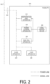
- the facility 300 includes the photovoltaic cell apparatus 310, the power storage apparatus 320, the fuel cell apparatus 330, a blind apparatus 340, a load apparatus 350, the local control device 360, and a measurement apparatus 390.
- the photovoltaic cell apparatus 310 is a distributed power supply that generates power in response to sunlight or other light.
- the photovoltaic cell apparatus 310 may be an example of the distributed power supply used in the VPP.
- the photovoltaic cell apparatus 310 includes a power conditioning system (PCS) and a solar panel.
- PCS power conditioning system
- the power storage apparatus 320 is a distributed power supply that charges and discharges the power.
- the power storage apparatus 320 may be an example of the distributed power supply used in the VPP.
- the power storage apparatus 320 includes a PCS and a power storage cell.
- the fuel cell apparatus 330 is a distributed power supply that generates power using fuel.
- the fuel cell apparatus 330 may be an example of the distributed power supply used in the VPP.
- the fuel cell apparatus 330 includes a PCS and a fuel cell.
- the fuel cell apparatus 330 may be a solid oxide fuel cell (SOFC), a polymer electrolyte fuel cell (PEFC), a phosphoric acid fuel cell (PAFC), or a molten carbonate fuel cell (MCFC).
- SOFC solid oxide fuel cell
- PEFC polymer electrolyte fuel cell
- PAFC phosphoric acid fuel cell
- MCFC molten carbonate fuel cell
- the blind apparatus 340 is an apparatus attached to a window or the like and can block sunlight from entering a space in which the blind apparatus 340 is installed.
- the blind apparatus 340 may be attached to the window inside or outside of the space in which the blind apparatus 340 is installed.
- the blind apparatus 340 includes a plurality of slats and controls the plurality of slats through a motor or the like.
- Each slat has a rectangular front surface and a rectangular back surface.
- the rectangular front surface may be a convex surface curved slightly outward (hereinafter, convex surface).
- the rectangular back surface may be a concave surface curved slightly inward (hereinafter, concave surface).
- the control of the slats may include control of at least one selected from the group consisting of raising the slats, lowering the slats, and adjusting the angles of the slats.
- the control of the slats may include control of a part of the plurality of slats. That is, the control of the slats may include control of a predetermined number of slats among the plurality of slats.
- the blind apparatus 340 may be of a horizontal type in which slats horizontally extending relative to a ground surface or a floor surface are vertically arranged relative to the ground surface or the floor surface, or may be of a vertical type in which slats vertically extending relative to the ground surface or the floor surface are horizontally arranged relative to the ground surface or the floor surface.
- the blind apparatus 340 may be referred to as an electric blind.
- the blind apparatus 340 may be referred to as a PV-equipped electric blind.
- the blind apparatus 340 includes slats on each of which a photovoltaic cell (hereinafter, referred to as a PV cell) is disposed.
- the PV cell is disposed on a surface of the slat.
- the PV cell is disposed on a convex surface of the slat.
- the PV cell may be disposed on a concave surface of the slat or on both the convex and concave surfaces of the slat.
- the blind apparatus 340 may be considered as an example of the distributed power supply that generates power in response to light such as sunlight.
- the blind apparatus 340 may or may not include a PCS.
- the PCS of the photovoltaic cell apparatus 310 may be used as the PCS of the PV cell disposed on the slat.
- the blind apparatus 340 will be described in detail below (see FIG. 3 ).
- the load apparatus 350 is an apparatus that consumes power.
- the load apparatus 350 is an air conditioning apparatus, an illumination apparatus, an audio visual (AV) apparatus, or the like.
- AV audio visual
- the local control device 360 is an example of a control device controlling the blind apparatus 340.
- the local control device 360 may be a device (energy management system (EMS)) managing the power of the facility 300.
- the local control device 360 may control an operating state of the photovoltaic cell apparatus 310, an operating state of the power storage apparatus 320, or an operating state of the fuel cell apparatus 330.
- the local control device 360 may control an operating state of the blind apparatus 340 or an operating state of the load apparatus 350.
- the local control device 360 will be described in detail below (see FIG. 4 ).
- the local control device 360 may also control two or more apparatuses selected from the above-described apparatuses.
- the measurement apparatus 390 is an example of a measurement apparatus measuring power related to the facility 300.
- the measurement apparatus 390 may measure the flow power from the power grid 110 to the facility 300 as the power related to the facility. That is, the electric power related to the facility 300 may be considered as the demanded power of the facility 300.
- the measurement apparatus 390 may measure the reverse flow power from the facility 300 to the power grid 110 as the power related to the facility. A value measured by the measurement apparatus 390 may be referred to as a measurement value.
- the measurement apparatus 390 may transmit a message including an information element indicating the power related to the facility 300 at a first cycle (e.g., one minute).
- the measurement apparatus 390 may transmit the message to the local control device 360 or to the management server 200.
- the measurement apparatus 390 may autonomously transmit the message or may transmit the message in response to a request from a transmission target.
- the measurement apparatus 390 may be a smart meter belonging to a business operator managing the power grid 110.
- communication between the management server 200 and the local control device 360 is performed in accordance with a first protocol.
- communication between the local control device 360 and the distributed power supply is performed in accordance with a second protocol different from the first protocol.
- a protocol based on open automated demand response (ADR) or a unique dedicated protocol can, for example, be used as the first protocol.
- a protocol based on ECHONET Lite, smart energy profile (SEP) 2.0, KNX, or a unique dedicated protocol can, for example, be used as the second protocol.
- both the first protocol and the second protocol may be unique dedicated protocols made having different rules. However, the first protocol and the second protocol may also be made having the same rules.
- the blind apparatus 340 includes a communicator 341, slats 342, and a controller 343.
- the communicator 341 includes a communication module.
- the communication module may be a wireless communication module conforming to standards such as IEEE 802.11a/b/g/n, ZigBee, Wi-SUN, LTE, and 5G, or may be a wired communication module conforming to a standard such as IEEE 802.3.
- the communicator 341 controls communication between the blind apparatus 340 and the local control device 360.
- the communicator 341 communicates with the local control device 360.
- Such communication is performed using a protocol based on the second protocol.
- ECHONET Lite will be mainly described as an example of the second protocol.
- the information element included in the message used in communication may include an information element for specifying the operating state of the blind apparatus 340.
- the operating state may include at least one selected from the group consisting of a first operating state, a second operating state, and a third operating state.
- the first operating state is an operating state in which the angles of the slats 342 are adjusted to maximize generated power of the PV cells. That is, in the first operating state, the generated power of the PV cells is prioritized over sunlight entering the space in which the blind apparatus 340 is installed.
- the second operating state is an operating state in which the angles of the slats 342 maximizing the generated power of the PV cells are searched for. Specifically, in the second operating state, the angles of the slats 342 maximizing the generated power of the PV cells are searched for by measuring the generated power of the PV cells while gradually changing the angles of the slats 342.
- the slats 342 whose angles are changed in a scan mode may be a part of the plurality of slats 342 provided in the blind apparatus 340.
- the third operating state is an operating state in which the angles of the slats 342 are adjusted based on an illuminance and/or a temperature of the space in which the blind apparatus 340 is installed.
- the angles of the slats 342 may be adjusted such that the illuminance of the space in which the blind apparatus 340 is installed reaches a target illuminance.
- a sensor that detects the illuminance may be provided in the blind apparatus 340 or may be configured to be able to communicate with the blind apparatus 340.
- the target illuminance may be set by the user.
- the angles of the slats 342 may be adjusted such that the temperature of the space in which the blind apparatus 340 is installed reaches a target temperature.
- a sensor that detects the temperature may be provided in the blind apparatus 340 or may be configured to be able to communicate with the blind apparatus 340.
- the target temperature may be set by the user.
- Such a message may include a message (e.g., SET command) instructing that the blind apparatus 340 be controlled in the operating state or a message (e.g., GET command) requesting the operating state applied to the blind apparatus 340.
- a message may include a message (e.g., GET response command, INF command) for a notification of the operating state applied to the blind apparatus 340.
- the GET response command is a command transmitted in response to the GET command
- the INF command is a message autonomously transmitted by the blind apparatus 340.
- the SET command includes an information element for the blind apparatus 340 to specify the operating state of the blind apparatus 340.
- the GET response command and the INF command include an information element for the local control device 360 to specify the operating state of the blind apparatus 340.
- the information element included in the message used in the communication may include an information element for specifying an abnormal state of the blind apparatus 340.
- the abnormal state may include at least one selected from the group consisting of a first abnormal state, a second abnormal state, and a third abnormal state.
- the first abnormal state is an abnormal state caused by the temperature of the space in which the blind apparatus 340 is installed.
- the blind apparatus 340 may determine that the first abnormal state occurs when the temperature of the space in which the blind apparatus 340 is installed exceeds a threshold value.
- the first abnormal state may be an abnormal state occurring when the temperature exceeds the threshold value due to a fire or the like.
- a sensor that detects the temperature may be provided in the blind apparatus 340 or may be configured to be able to communicate with the blind apparatus 340.
- the third abnormal state is an abnormal state caused by contact with the slats 342 and/or deformation of the slats 342.
- the blind apparatus 340 may determine that the third abnormal state occurs when contact with the slats 342 and/or deformation of the slats 342 is detected.
- the third abnormal state may be an abnormal state occurring when the user touches the slats 342.
- a sensor that detects shaking and/or an impact may be provided in the blind apparatus 340 or may be configured to be able to communicate with the blind apparatus 340.
- Such a message may include a message (e.g., GET command) requesting the abnormal state occurring in the blind apparatus 340.
- a message may include a message (e.g., GET response command, INF command) for a notification of the abnormal state occurring in the blind apparatus 340.
- the GET response command is a command transmitted in response to the GET command
- the INF command is a message autonomously transmitted by the blind apparatus 340.
- the GET response command and the INF command include an information element for the local control device 360 to specify the abnormal state of the blind apparatus 340.
- the information element included in the message used in the communication may include an information element for specifying a grid interconnection state indicating whether the PV cells are interconnected with the power grid 110.
- the grid interconnection state may include a state in which the PV cells are interconnected with the power grid 110 (e.g., grid interconnection) or a state in which the PV cells are disconnected from the power grid 110 (e.g., independent).
- the state in which the PV cells are interconnected with the power grid 110 may include a state in which the reverse power flow of the output power of the PV cells is permitted (e.g., grid interconnection (reverse power flow is possible)) or a state in which the reverse power flow of the output power of the PV cells is not permitted (e.g., grid interconnection (reverse power flow is impossible)).
- the grid interconnection state may include a state in which it is unknown whether the PV cells are interconnected with the power grid 110 (e.g., unknown).
- Such a message may include a message requesting the grid interconnection state (e.g., GET command).
- a message may include a message (e.g., GET response command, INF command) for a notification of the grid interconnection state.
- the GET response command is a command transmitted in response to the GET command
- the INF command is a message autonomously transmitted by the blind apparatus 340.
- the GET response command and the INF command include an information element for the local control device 360 to specify the grid interconnection state.
- the slats 342 are members for adjusting sunlight entering the space in which the blind apparatus 340 is installed.
- the PV cell may be disposed on the surface of each slat 342.
- the controller 343 may include at least one processor.
- the at least one processor may include a single integrated circuit (IC) or a plurality of circuits (such as integrated circuits and/or discrete circuits) connected communicably with one another.
- the controller 343 may be referred to as a first controller.
- the controller 343 may execute control of at least one selected from the group consisting of raising the slats 342, lowering the slats 342, and adjusting the angles of the slats 342.
- the controller 343 may control a part of the plurality of slats 342. That is, the controller 343 may control a predetermined number of slats among the plurality of slats.
- the controller 343 may control any one of the first operating state, the second operating state, and the third operating state.
- the controller 343 may detect any one of the first abnormal state, the second abnormal state, and the third abnormal state.
- the local control device 360 includes a first communicator 361, a second communicator 362, and a controller 363.
- the first communicator 361 communicates with the management server 200 via the network 120. As described above, the first communicator 361 communicates in accordance with the first protocol. For example, the first communicator 361 receives a first message from the management server 200 in accordance with the first protocol. The first communicator 361 transmits a first message response to the management server 200 in accordance with the first protocol.
- the second communicator 362 includes a communication module.
- the communication module may be a wireless communication module conforming to standards such as IEEE 802.11a/b/g/n, ZigBee, Wi-SUN, LTE, and 5G, or may be a wired communication module conforming to a standard such as IEEE 802.3.
- the second communicator 362 communicates with the distributed power supply (the photovoltaic cell apparatus 310, the power storage apparatus 320, or the fuel cell apparatus 330). As described above, the second communicator 362 communicates in accordance with the second protocol. For example, the second communicator 362 transmits a second message to the distributed power supply in accordance with the second protocol. The second communicator 362 receives a second message response from the distributed power supply in accordance with the second protocol.
- the distributed power supply the photovoltaic cell apparatus 310, the power storage apparatus 320, or the fuel cell apparatus 330.
- the second communicator 362 communicates in accordance with the second protocol.
- the second communicator 362 transmits a second message to the distributed power supply in accordance with the second protocol.
- the second communicator 362 receives a second message response from the distributed power supply in accordance with the second protocol.
- the second message may be a message including an information element for specifying the operating state of the blind apparatus 340, a message including an information element for specifying the abnormal state occurring in the blind apparatus 340, or a message including an information element for specifying the grid interconnection state indicating whether the PV cells are interconnected with the power grid 110.
- the controller 363 may include at least one processor.
- the at least one processor may include a single integrated circuit (IC) or a plurality of circuits (such as integrated circuits and/or discrete circuits) connected communicably with one another.
- the controller 363 may be referred to as a second controller.
- the controller 363 controls each component provided in the local control device 360. Specifically, the controller 363 instructs the blind apparatus 340 to set the operating state by transmitting the second message and receiving the second message response. The controller 363 may instruct the blind apparatus 340 to report the abnormal state by transmitting the second message and receiving the second message response.
- each message is defined by a property name, property contents, and a message type.
- the property name is the name of a property adopted in the blind apparatus 340.
- the property contents are the contents of the property adopted in the blind apparatus 340.
- the message type is the message type (command type such as SET, GET, and INF) to which each property can be applied.
- the property may be considered as data for distinguishing an information element included in the message.
- An operating state, abnormality contents, a grid interconnection state, and the like may be defined as the property.
- Possible information elements of the operating state may include power-ON of the blind apparatus 340 and power-OFF of the blind apparatus 340.
- possible information elements of the operating state may include the first operating state, the second operating state, and the third operating state described above.
- Possible information elements of the abnormality contents may include reset, stuck obstacle, power recovery, type-out, and battery amount reduction.
- possible information elements of the abnormality contents may include the first abnormal state, the second abnormal state, and the third abnormal state described above.
- Possible information elements of the grid interconnection state may include grid interconnection (reverse power flow is possible), independent, grid interconnection (reverse power flow is impossible), and unknown.
- step S10 the local control device 360 transmits, to the blind apparatus 340, the SET command instructing that the blind apparatus 340 be controlled in the operating state.
- the SET command includes an information element for specifying the operating state to be applied to the blind apparatus 340.
- the blind apparatus 340 transmits the SET response command in response to the SET command.
- the SET response command includes an information element indicating that the SET command has been received.
- the SET response command does not need to include an information element specifying the operating state applied to the blind apparatus 340.
- step S12 the local control device 360 transmits, to the blind apparatus 340, the GET command requesting the operating state applied to the blind apparatus 340.
- step S13 the blind apparatus 340 transmits the GET response command in response to the GET command.
- the GET response command includes an information element specifying the operating state applied to the blind apparatus 340.
- the blind apparatus 340 transmits the INF command in response to a predetermined trigger.
- the INF command includes an information element specifying the operating state applied to the blind apparatus 340.
- the predetermined trigger may include a periodic trigger and may also include a change in the operating state of the blind apparatus 340.
- the predetermined trigger may include power failure and power recovery.
- step S20 the GET command requesting the abnormal state occurring in the blind apparatus 340 is transmitted to the blind apparatus 340.
- step S21 the blind apparatus 340 transmits the GET response command in response to the GET command.
- the GET response command includes an information element specifying the abnormal state occurring in the blind apparatus 340.
- the blind apparatus 340 transmits the INF command in response to a predetermined trigger.
- the INF command includes an information element specifying the abnormal state occurring in the blind apparatus 340.
- the predetermined trigger may include a periodic trigger and may also include a change in the abnormal state of the blind apparatus 340.
- the predetermined trigger may include power failure, power recovery, and the like.
- step S30 the GET command requesting the grid interconnection state of the blind apparatus 340 is transmitted to the blind apparatus 340.
- step S31 the blind apparatus 340 transmits the GET response command in response to the GET command.
- the GET response command includes an information element specifying the grid interconnection state of the blind apparatus 340.
- the blind apparatus 340 transmits the INF command in response to a predetermined trigger.
- the INF command includes an information element specifying the grid interconnection state of the blind apparatus 340.
- the predetermined trigger may include a periodic trigger and may also include a change in the abnormal state of the blind apparatus 340.
- the predetermined trigger may include power failure, power recovery, and the like.
- the blind apparatus 340 communicates, to the local control device 360, a message including an information element for specifying the operating state of the blind apparatus 340.
- the operating state includes at least one selected from the group consisting of the first operating state, the second operating state, and the third operating state.
- the blind apparatus 340 communicates, to the local control device 360, a message including an information element for specifying the abnormal state of the blind apparatus 340.
- the abnormal state includes at least one selected from the group consisting of the first abnormal state, the second abnormal state, and the third abnormal state.
- the blind apparatus 340 communicates, to the local control device 360, a message including an information element for specifying the grid interconnection state of the blind apparatus 340.
- Variation 1 of the embodiment will be described below. Differences from the embodiment will be mainly described below.
- the blind apparatus 340 communicates a message including an information element indicating the generated power of the slats 342.
- the message may be the above described GET command, GET response command, or INF command.
- the information element may include an information element indicating the generated power of each slat 342.
- the information element may include an information element indicating the generated power of all the slats 342.
- the information element may include an information element indicating an instantaneous value of the generated power (measured value of instantaneous generated power) or may include an information element indicating a cumulative value of the generated power (measured value of a cumulative generated power).
- the local control device 360 may determine a deterioration state of the slats 342 based on the generated power of the slats 342. Specifically, when the generated power of each slat 342 can be known, the local control device 360 may determine the deterioration state of each slat 342. When the generated power of all the slats 342 can be known, the local control device 360 may determine the deterioration state of all the slats 342.
- the local control device 360 may also communicate a message described below.
- the local control device 360 may communicate a message including an information element indicating an open or closed state of the slats 342.
- the open or closed state of the slats 342 may include a state in which all the slats 342 are raised (open state) and a state in which all the slats 342 are lowered (closed state).
- the open or closed state of the slats 342 may include a state between the open state and the closed state (i.e., a degree of raising the slats 342 or a degree of lowering the slats 342).
- the local control device 360 may communicate a message including an information element indicating the angles of the slats 342.
- the blind apparatus 340 may detect the abnormal state of the PV cells disposed on the slats 342 based on the generated power of the slats 342. For example, the blind apparatus 340 may detect the abnormal state of the PV cells disposed on the slats 342 when the generated power of the slats 342 is less than a threshold value regardless of the amount of light (sunlight) the PV cells are irradiated with (sunlight). In such a case, the blind apparatus 340 may communicate a message including an information element indicating the abnormal state in which the generated power of the slats 342 (PV cells) is less than the threshold value. The message may be the above described GET command, GET response command, or INF command.
- Variation 2 of the embodiment will be described below. Differences from the embodiment will be mainly described below.
- the blind apparatus 340 includes a power storage apparatus for driving the slats 342.
- the blind apparatus 340 may communicate a message including an information element indicating a remaining amount of power stored in the power storage apparatus.
- the message may be the above described GET command, GET response command, or INF command.
- the local control device 360 can appropriately control the blind apparatus 340 based on the remaining amount of power stored in the power storage apparatus. For example, when the remaining amount of the stored power is less than a threshold value, the local control device 360 can control the blind apparatus 340 to actively generate power using the PV cells disposed on the slats 342.
- the blind apparatus 340 may communicate a message including an information element indicating an operating mode of the power storage apparatus.
- the message may be the above-described SET command, GET command, GET response command, or INF command.
- the operating mode of the power storage apparatus may include a quick charge mode, a power reception mode, a discharge mode, a standby mode, a test mode, an automatic mode, and the like.
- the local control device 360 can appropriately secure power for driving the slats 342 by setting the operating mode of the power storage apparatus in the blind apparatus 340. For example, when the remaining amount of the stored power is less than a threshold value, the local control device 360 can suppress depletion of power for driving the slats 342 by actively charging the power storage apparatus.
- the local control device 360 may instruct the blind apparatus 340 to raise the slats 342 in response to the abnormal state (e.g., the first abnormal state to the third abnormal state) of the blind apparatus 340.
- the operating state may include a fourth operating state in which the angles of the slats 342 are fixed at an angle set by the user.
- the operating state may include a fifth operating state in which the convex surfaces of the slats 342 on which the PV cells are disposed are fixed to face outward relative to the space in which the blind apparatus 340 is installed. That is, in the fifth operating state, blocking sunlight from entering the space in which the blind apparatus 340 is installed is prioritized over the generated power of the PV cells. As a result, in the daytime, the space in which the blind apparatus 340 is installed can be darkened while sunlight from outside to the space is blocked. In the fifth operating state, since the PV cells face outward, it is possible to obtain power generated through the PV cells being irradiated with sunlight, while sunlight entering the space in which the blind apparatus 340 is installed is blocked.
- the operating state may include a sixth operating state in which the convex surfaces of the slats 342 on which the PV cells are disposed are fixed to face inward relative to the space in which the blind apparatus 340 is installed. This makes it difficult for indoor light to leak outside at night from the space in which the blind apparatus 340 is installed.
- the sixth operating state since the PV cells face inward, it is possible to obtain power generated through the PV cells being irradiated with indoor light, while it is difficult for the indoor light to leak outside from the space in which the blind apparatus 340 is installed.
- the operating state may include a seventh operating state in which the convex surfaces of the slats 342 are fixed toward a ceiling relative to the space in which the blind apparatus 340 is installed. This enables a large amount of sunlight to enter the space in which the blind apparatus 340 is installed from outside and can thus light up the space.
- the PV cells face the ceiling in the seventh operating state, the PV cells are also irradiated with sunlight from the outside, and it is thus possible to obtain the generated power of the PV cells while a large amount of sunlight enters the space in which the blind apparatus 340 is installed.
- the operating state may include an eighth operating state in which the slats 342 are rotated 90 degrees or 270 degrees relative to the angles of the slats 342 maximizing the generated power of the PV cells.
- the operating state may include a ninth operating state in which a predetermined number of slats 342 among the plurality of slats 342 stacked in one direction and stored are lowered.
- the ninth operating state is a state in which seven of the ten slats 342 are lowered. In this case, the remaining three slats 342 are in a stacked state.
- the ninth operating state may include a state in which all the slats 342 of the blind apparatus 340 are lowered or may include a state in which none of the slats 342 are lowered.
- the predetermined number may be the number of slats counted from the top or from the bottom in a state in which all the slats 342 of the blind apparatus 340 are lowered. This makes it possible to know, among the plurality of slats 342, which PV cells frequently generate power and which PV cells infrequently generate power, which leads to improvement in maintenance of the blind apparatus 340.
- a ratio with respect to all of the plurality of slats 342 of the blind apparatus 340 may be used.
- ECHONET Lite has been mainly described. However, the disclosure described above is not limited thereto. The above disclosure is also applicable to other protocols such as SEP 2.0 and KNX.
- the local control device 360 may be executed by a server disposed in the network 120.
- the local control device 360 may be provided through a cloud service.
Landscapes
- Engineering & Computer Science (AREA)
- Structural Engineering (AREA)
- Architecture (AREA)
- Civil Engineering (AREA)
- Blinds (AREA)
- Special Wing (AREA)
- Operating, Guiding And Securing Of Roll- Type Closing Members (AREA)
- Selective Calling Equipment (AREA)
- Remote Monitoring And Control Of Power-Distribution Networks (AREA)
Abstract
Description
- The present disclosure relates to a blind apparatus.
- A technology has recently been proposed in which photovoltaic (PV) cells are disposed on the surfaces of slats in a blind apparatus including the slats. Regarding such a technology, a technology for protecting, from damage, a lead wire for drawing power from the PV cells has also been proposed (e.g., Patent Document 1).
- When the above-described blind apparatus is controlled, communication between the blind apparatus and a control device (e.g., energy management system (EMS)) that controls the blind apparatus is necessary. In particular, a case is also expected in which the control device and the blind apparatus are provided by different entities.
- Under such circumstances, the inventors have found as a result of intensive study that it is necessary to appropriately define an information element included in a message used in communication between the control device and the blind apparatus in order to appropriately control the blind apparatus.
- Patent Document 1:
WO 2020/116413 - The gist of a first feature is a blind apparatus including a slat on which a photovoltaic cell is disposed, and a communicator configured to perform communication between the blind apparatus and a control device configured to control the blind apparatus, wherein an information element included in a message used in the communication includes an information element for specifying an operating state of the blind apparatus, and the operating state includes at least one selected from the group consisting of a first operating state in which an angle of the slat is adjusted to maximize generated power of the photovoltaic cell, a second operating state in which the angle of the slat maximizing the generated power of the photovoltaic cell is searched for, and a third operating state in which the angle of the slat is adjusted based on an illuminance and/or a temperature of a space in which the blind apparatus is installed.
- The gist of a second feature is a blind apparatus including a slat on which a photovoltaic cell is disposed, and a communicator configured to perform communication between the blind apparatus and a control device configured to control the blind apparatus, wherein an information element included in a message used in the communication includes an information element for specifying an abnormal state of the blind apparatus, and the abnormal state includes at least one selected from the group consisting of a first abnormal state caused by a temperature of a space in which the blind apparatus is installed, a second abnormal state caused by shaking of the slat and/or an impact to the slat, and a third abnormal state caused by contact with the slat and/or deformation of the slat.
- The gist of a third feature is a blind apparatus including a slat on which a photovoltaic cell is disposed, and a communicator configured to perform communication between the blind apparatus and a control device configured to control the blind apparatus, wherein an information element included in a message used in the communication includes an information element for specifying a grid interconnection state indicating whether the photovoltaic cell is interconnected with a power grid.
-
-
FIG. 1 is a diagram illustrating apower management system 100 according to an embodiment. -
FIG. 2 is a diagram illustrating afacility 300 according to the embodiment. -
FIG. 3 is a diagram illustrating ablind apparatus 340 according to the embodiment. -
FIG. 4 is a diagram illustrating alocal control device 360 according to the embodiment. -
FIG. 5 is a diagram showing message examples according to the embodiment. -
FIG. 6 is a diagram for describing an operation example according to the embodiment. -
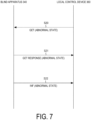
FIG. 7 is a diagram for describing the operation example according to the embodiment. -
FIG. 8 is a diagram for describing the operation example according to the embodiment. - Embodiments will be described below with reference to the accompanying drawings. Note that in the following description of the drawings, the same or similar components will be denoted by the same or similar reference signs. However, the drawings are schematic.
- A power management system according to an embodiment will be described below.
- As illustrated in
FIG. 1 , apower management system 100 includes amanagement server 200 andfacilities 300. InFIG. 1 ,facilities 300A to 300C are illustrated as examples of thefacilities 300. - Each
facility 300 is connected to apower grid 110. In the following description, the flow of power from thepower grid 110 to thefacility 300 is referred to as power flow, and the flow of power from thefacility 300 to thepower grid 110 is referred to as reverse power flow. Power flowing from thepower grid 110 to thefacility 300 may be referred to as demanded power. Demanded power may also be a concept including power reversely flowing from thefacility 300 to thepower grid 110. In such a case, the flow power may be expressed as a positive value, and the reverse flow power may be expressed as a negative value. - The
management server 200 and thefacility 300 are connected to anetwork 120. Thenetwork 120 is only required to provide a line between themanagement server 200 and thefacility 300. For example, thenetwork 120 may include the Internet. Thenetwork 120 may include a dedicated line such as a virtual private network (VPN). - The
management server 200 is an example of a power management server that adjusts the supply-demand balance of thepower grid 110. Themanagement server 200 is a server managed by a business operator, such as a power generation operator, a power transmission and distribution operator, a retailer, or a resource aggregator. The resource aggregator is an electric power provider that provides the reverse flow power to the power generation operator, the power transmission and distribution operator, the retailer, and the like in a virtual power plant (VPP). The resource aggregator may be an electric power provider that generates reduced power of the flow power (power consumption) of thefacility 300 managed by the resource aggregator. - The
management server 200 transmits, to alocal control device 360 provided in thefacility 300, a control message instructing control of a distributed power supply (e.g., aphotovoltaic cell apparatus 310, apower storage apparatus 320, or a fuel cell apparatus 330) provided in thefacility 300. For example, themanagement server 200 may transmit a power flow control message requesting control of the power flow or may transmit a reverse power flow control message requesting control of the reverse power flow. Themanagement server 200 may transmit a power supply control message for controlling an operating state of the distributed power supply. A degree of control of the power flow or the reverse power flow may be expressed as an absolute value (e.g., XX kW) or may be expressed as a relative value (e.g., XX%). The degree of control of the power flow or the reverse power flow may be expressed by using two or more levels. The degree of control of the power flow or the reverse power flow may be expressed as a power rate (real time pricing (RTP)) determined according to a current power supply-demand balance or may be expressed as a power rate (time of use (TOU)) determined according to a past power supply-demand balance. - As illustrated in
FIG. 2 , thefacility 300 includes thephotovoltaic cell apparatus 310, thepower storage apparatus 320, thefuel cell apparatus 330, ablind apparatus 340, aload apparatus 350, thelocal control device 360, and ameasurement apparatus 390. - The
photovoltaic cell apparatus 310 is a distributed power supply that generates power in response to sunlight or other light. Thephotovoltaic cell apparatus 310 may be an example of the distributed power supply used in the VPP. For example, thephotovoltaic cell apparatus 310 includes a power conditioning system (PCS) and a solar panel. - The
power storage apparatus 320 is a distributed power supply that charges and discharges the power. Thepower storage apparatus 320 may be an example of the distributed power supply used in the VPP. For example, thepower storage apparatus 320 includes a PCS and a power storage cell. - The
fuel cell apparatus 330 is a distributed power supply that generates power using fuel. Thefuel cell apparatus 330 may be an example of the distributed power supply used in the VPP. For example, thefuel cell apparatus 330 includes a PCS and a fuel cell. - For example, the
fuel cell apparatus 330 may be a solid oxide fuel cell (SOFC), a polymer electrolyte fuel cell (PEFC), a phosphoric acid fuel cell (PAFC), or a molten carbonate fuel cell (MCFC). - The
blind apparatus 340 is an apparatus attached to a window or the like and can block sunlight from entering a space in which theblind apparatus 340 is installed. Theblind apparatus 340 may be attached to the window inside or outside of the space in which theblind apparatus 340 is installed. Specifically, theblind apparatus 340 includes a plurality of slats and controls the plurality of slats through a motor or the like. - Each slat has a rectangular front surface and a rectangular back surface. The rectangular front surface may be a convex surface curved slightly outward (hereinafter, convex surface). The rectangular back surface may be a concave surface curved slightly inward (hereinafter, concave surface). The control of the slats may include control of at least one selected from the group consisting of raising the slats, lowering the slats, and adjusting the angles of the slats. The control of the slats may include control of a part of the plurality of slats. That is, the control of the slats may include control of a predetermined number of slats among the plurality of slats.
- The
blind apparatus 340 may be of a horizontal type in which slats horizontally extending relative to a ground surface or a floor surface are vertically arranged relative to the ground surface or the floor surface, or may be of a vertical type in which slats vertically extending relative to the ground surface or the floor surface are horizontally arranged relative to the ground surface or the floor surface. Theblind apparatus 340 may be referred to as an electric blind. Theblind apparatus 340 may be referred to as a PV-equipped electric blind. - In the embodiment, the
blind apparatus 340 includes slats on each of which a photovoltaic cell (hereinafter, referred to as a PV cell) is disposed. The PV cell is disposed on a surface of the slat. Specifically, the PV cell is disposed on a convex surface of the slat. The PV cell may be disposed on a concave surface of the slat or on both the convex and concave surfaces of the slat. Theblind apparatus 340 may be considered as an example of the distributed power supply that generates power in response to light such as sunlight. Theblind apparatus 340 may or may not include a PCS. The PCS of thephotovoltaic cell apparatus 310 may be used as the PCS of the PV cell disposed on the slat. Theblind apparatus 340 will be described in detail below (seeFIG. 3 ). - The
load apparatus 350 is an apparatus that consumes power. For example, theload apparatus 350 is an air conditioning apparatus, an illumination apparatus, an audio visual (AV) apparatus, or the like. - The
local control device 360 is an example of a control device controlling theblind apparatus 340. Thelocal control device 360 may be a device (energy management system (EMS)) managing the power of thefacility 300. Thelocal control device 360 may control an operating state of thephotovoltaic cell apparatus 310, an operating state of thepower storage apparatus 320, or an operating state of thefuel cell apparatus 330. Thelocal control device 360 may control an operating state of theblind apparatus 340 or an operating state of theload apparatus 350. Thelocal control device 360 will be described in detail below (seeFIG. 4 ). Thelocal control device 360 may also control two or more apparatuses selected from the above-described apparatuses. - The
measurement apparatus 390 is an example of a measurement apparatus measuring power related to thefacility 300. Themeasurement apparatus 390 may measure the flow power from thepower grid 110 to thefacility 300 as the power related to the facility. That is, the electric power related to thefacility 300 may be considered as the demanded power of thefacility 300. Themeasurement apparatus 390 may measure the reverse flow power from thefacility 300 to thepower grid 110 as the power related to the facility. A value measured by themeasurement apparatus 390 may be referred to as a measurement value. Themeasurement apparatus 390 may transmit a message including an information element indicating the power related to thefacility 300 at a first cycle (e.g., one minute). Themeasurement apparatus 390 may transmit the message to thelocal control device 360 or to themanagement server 200. Themeasurement apparatus 390 may autonomously transmit the message or may transmit the message in response to a request from a transmission target. Themeasurement apparatus 390 may be a smart meter belonging to a business operator managing thepower grid 110. - In the embodiment, communication between the
management server 200 and thelocal control device 360 is performed in accordance with a first protocol. On the other hand, communication between thelocal control device 360 and the distributed power supply (thephotovoltaic cell apparatus 310, thepower storage apparatus 320, or the fuel cell apparatus 330) is performed in accordance with a second protocol different from the first protocol. A protocol based on open automated demand response (ADR) or a unique dedicated protocol can, for example, be used as the first protocol. A protocol based on ECHONET Lite, smart energy profile (SEP) 2.0, KNX, or a unique dedicated protocol can, for example, be used as the second protocol. For example, both the first protocol and the second protocol may be unique dedicated protocols made having different rules. However, the first protocol and the second protocol may also be made having the same rules. - The blind apparatus according to the embodiment will be described below. As illustrated in
FIG. 3 , theblind apparatus 340 includes acommunicator 341,slats 342, and acontroller 343. - The
communicator 341 includes a communication module. The communication module may be a wireless communication module conforming to standards such as IEEE 802.11a/b/g/n, ZigBee, Wi-SUN, LTE, and 5G, or may be a wired communication module conforming to a standard such as IEEE 802.3. - For example, the
communicator 341 controls communication between theblind apparatus 340 and thelocal control device 360. In other words, thecommunicator 341 communicates with thelocal control device 360. Such communication is performed using a protocol based on the second protocol. Hereinafter, ECHONET Lite will be mainly described as an example of the second protocol. - Firstly, the information element included in the message used in communication may include an information element for specifying the operating state of the
blind apparatus 340. The operating state may include at least one selected from the group consisting of a first operating state, a second operating state, and a third operating state. - The first operating state is an operating state in which the angles of the
slats 342 are adjusted to maximize generated power of the PV cells. That is, in the first operating state, the generated power of the PV cells is prioritized over sunlight entering the space in which theblind apparatus 340 is installed. - The second operating state is an operating state in which the angles of the
slats 342 maximizing the generated power of the PV cells are searched for. Specifically, in the second operating state, the angles of theslats 342 maximizing the generated power of the PV cells are searched for by measuring the generated power of the PV cells while gradually changing the angles of theslats 342. Theslats 342 whose angles are changed in a scan mode may be a part of the plurality ofslats 342 provided in theblind apparatus 340. - As described above, the third operating state is an operating state in which the angles of the
slats 342 are adjusted based on an illuminance and/or a temperature of the space in which theblind apparatus 340 is installed. Specifically, in the third operating state, the angles of theslats 342 may be adjusted such that the illuminance of the space in which theblind apparatus 340 is installed reaches a target illuminance. A sensor that detects the illuminance may be provided in theblind apparatus 340 or may be configured to be able to communicate with theblind apparatus 340. The target illuminance may be set by the user. In the third operating state, the angles of theslats 342 may be adjusted such that the temperature of the space in which theblind apparatus 340 is installed reaches a target temperature. A sensor that detects the temperature may be provided in theblind apparatus 340 or may be configured to be able to communicate with theblind apparatus 340. The target temperature may be set by the user. - Such a message may include a message (e.g., SET command) instructing that the
blind apparatus 340 be controlled in the operating state or a message (e.g., GET command) requesting the operating state applied to theblind apparatus 340. Such a message may include a message (e.g., GET response command, INF command) for a notification of the operating state applied to theblind apparatus 340. The GET response command is a command transmitted in response to the GET command, and the INF command is a message autonomously transmitted by theblind apparatus 340. - Note that the SET command includes an information element for the
blind apparatus 340 to specify the operating state of theblind apparatus 340. The GET response command and the INF command include an information element for thelocal control device 360 to specify the operating state of theblind apparatus 340. - Secondly, the information element included in the message used in the communication may include an information element for specifying an abnormal state of the
blind apparatus 340. The abnormal state may include at least one selected from the group consisting of a first abnormal state, a second abnormal state, and a third abnormal state. - The first abnormal state is an abnormal state caused by the temperature of the space in which the
blind apparatus 340 is installed. Specifically, theblind apparatus 340 may determine that the first abnormal state occurs when the temperature of the space in which theblind apparatus 340 is installed exceeds a threshold value. For example, the first abnormal state may be an abnormal state occurring when the temperature exceeds the threshold value due to a fire or the like. A sensor that detects the temperature may be provided in theblind apparatus 340 or may be configured to be able to communicate with theblind apparatus 340. - The second abnormal state is an abnormal state caused by shaking of the
slats 342 and/or an impact to theslats 342. Theblind apparatus 340 may determine that the second abnormal state occurs when shaking of theslats 342 and/or an impact to theslats 342 is detected. For example, the second abnormal state may be an abnormal state occurring when wind or the like shakes theslats 342. A sensor that detects shaking and/or an impact may be provided in theblind apparatus 340 or may be configured to be able to communicate with theblind apparatus 340. - The third abnormal state is an abnormal state caused by contact with the
slats 342 and/or deformation of theslats 342. Theblind apparatus 340 may determine that the third abnormal state occurs when contact with theslats 342 and/or deformation of theslats 342 is detected. For example, the third abnormal state may be an abnormal state occurring when the user touches theslats 342. A sensor that detects shaking and/or an impact may be provided in theblind apparatus 340 or may be configured to be able to communicate with theblind apparatus 340. - Such a message may include a message (e.g., GET command) requesting the abnormal state occurring in the
blind apparatus 340. Such a message may include a message (e.g., GET response command, INF command) for a notification of the abnormal state occurring in theblind apparatus 340. The GET response command is a command transmitted in response to the GET command, and the INF command is a message autonomously transmitted by theblind apparatus 340. - Note that the GET response command and the INF command include an information element for the
local control device 360 to specify the abnormal state of theblind apparatus 340. - Thirdly, the information element included in the message used in the communication may include an information element for specifying a grid interconnection state indicating whether the PV cells are interconnected with the
power grid 110. - The grid interconnection state may include a state in which the PV cells are interconnected with the power grid 110 (e.g., grid interconnection) or a state in which the PV cells are disconnected from the power grid 110 (e.g., independent). The state in which the PV cells are interconnected with the
power grid 110 may include a state in which the reverse power flow of the output power of the PV cells is permitted (e.g., grid interconnection (reverse power flow is possible)) or a state in which the reverse power flow of the output power of the PV cells is not permitted (e.g., grid interconnection (reverse power flow is impossible)). The grid interconnection state may include a state in which it is unknown whether the PV cells are interconnected with the power grid 110 (e.g., unknown). - Such a message may include a message requesting the grid interconnection state (e.g., GET command). Such a message may include a message (e.g., GET response command, INF command) for a notification of the grid interconnection state. The GET response command is a command transmitted in response to the GET command, and the INF command is a message autonomously transmitted by the
blind apparatus 340. - Note that the GET response command and the INF command include an information element for the
local control device 360 to specify the grid interconnection state. - The
slats 342 are members for adjusting sunlight entering the space in which theblind apparatus 340 is installed. The PV cell may be disposed on the surface of eachslat 342. - The
controller 343 may include at least one processor. The at least one processor may include a single integrated circuit (IC) or a plurality of circuits (such as integrated circuits and/or discrete circuits) connected communicably with one another. Thecontroller 343 may be referred to as a first controller. - For example, the
controller 343 may execute control of at least one selected from the group consisting of raising theslats 342, lowering theslats 342, and adjusting the angles of theslats 342. Thecontroller 343 may control a part of the plurality ofslats 342. That is, thecontroller 343 may control a predetermined number of slats among the plurality of slats. Thecontroller 343 may control any one of the first operating state, the second operating state, and the third operating state. Thecontroller 343 may detect any one of the first abnormal state, the second abnormal state, and the third abnormal state. - A local control device according to the embodiment will be described below. As illustrated in
FIG. 4 , thelocal control device 360 includes afirst communicator 361, asecond communicator 362, and acontroller 363. - The
first communicator 361 includes a communication module. The communication module may be a wireless communication module conforming to standards such as IEEE 802.11a/b/g/n, ZigBee, Wi-SUN, LTE, and 5G, or may be a wired communication module conforming to a standard such as IEEE 802.3. - For example, the
first communicator 361 communicates with themanagement server 200 via thenetwork 120. As described above, thefirst communicator 361 communicates in accordance with the first protocol. For example, thefirst communicator 361 receives a first message from themanagement server 200 in accordance with the first protocol. Thefirst communicator 361 transmits a first message response to themanagement server 200 in accordance with the first protocol. - The
second communicator 362 includes a communication module. The communication module may be a wireless communication module conforming to standards such as IEEE 802.11a/b/g/n, ZigBee, Wi-SUN, LTE, and 5G, or may be a wired communication module conforming to a standard such as IEEE 802.3. - For example, the
second communicator 362 communicates with the distributed power supply (thephotovoltaic cell apparatus 310, thepower storage apparatus 320, or the fuel cell apparatus 330). As described above, thesecond communicator 362 communicates in accordance with the second protocol. For example, thesecond communicator 362 transmits a second message to the distributed power supply in accordance with the second protocol. Thesecond communicator 362 receives a second message response from the distributed power supply in accordance with the second protocol. - As described above, the second message may be a message including an information element for specifying the operating state of the
blind apparatus 340, a message including an information element for specifying the abnormal state occurring in theblind apparatus 340, or a message including an information element for specifying the grid interconnection state indicating whether the PV cells are interconnected with thepower grid 110. - The
controller 363 may include at least one processor. The at least one processor may include a single integrated circuit (IC) or a plurality of circuits (such as integrated circuits and/or discrete circuits) connected communicably with one another. Thecontroller 363 may be referred to as a second controller. - For example, the
controller 363 controls each component provided in thelocal control device 360. Specifically, thecontroller 363 instructs theblind apparatus 340 to set the operating state by transmitting the second message and receiving the second message response. Thecontroller 363 may instruct theblind apparatus 340 to report the abnormal state by transmitting the second message and receiving the second message response. - Messages according to the embodiment will be described below. The messages used in the communication between the
blind apparatus 340 and thelocal control device 360 will be described. Although the messages related to the disclosure will be mainly described with reference toFIG. 5 , messages including other information elements may also be defined. - As illustrated in
FIG. 5 , each message is defined by a property name, property contents, and a message type. The property name is the name of a property adopted in theblind apparatus 340. The property contents are the contents of the property adopted in theblind apparatus 340. The message type is the message type (command type such as SET, GET, and INF) to which each property can be applied. The property may be considered as data for distinguishing an information element included in the message. An operating state, abnormality contents, a grid interconnection state, and the like may be defined as the property. - Possible information elements of the operating state may include power-ON of the
blind apparatus 340 and power-OFF of theblind apparatus 340. In addition to these information elements, possible information elements of the operating state may include the first operating state, the second operating state, and the third operating state described above. - Possible information elements of the abnormality contents may include reset, stuck obstacle, power recovery, type-out, and battery amount reduction. In addition to these information elements, possible information elements of the abnormality contents may include the first abnormal state, the second abnormal state, and the third abnormal state described above.
- Possible information elements of the grid interconnection state may include grid interconnection (reverse power flow is possible), independent, grid interconnection (reverse power flow is impossible), and unknown.
- An operation example according to the embodiment will be described below. Hereinafter, a case will be described as an example in which a protocol used in the communication between the
blind apparatus 340 and thelocal control device 360 is a protocol conforming to ECHONET Lite. - Firstly, a sequence regarding the operating state will be described with reference to
FIG. 6 . - As illustrated in
FIG. 6 , in step S10, thelocal control device 360 transmits, to theblind apparatus 340, the SET command instructing that theblind apparatus 340 be controlled in the operating state. The SET command includes an information element for specifying the operating state to be applied to theblind apparatus 340. - In step S11, the
blind apparatus 340 transmits the SET response command in response to the SET command. The SET response command includes an information element indicating that the SET command has been received. The SET response command does not need to include an information element specifying the operating state applied to theblind apparatus 340. - In step S12, the
local control device 360 transmits, to theblind apparatus 340, the GET command requesting the operating state applied to theblind apparatus 340. - In step S13, the
blind apparatus 340 transmits the GET response command in response to the GET command. The GET response command includes an information element specifying the operating state applied to theblind apparatus 340. - In step S14, the
blind apparatus 340 transmits the INF command in response to a predetermined trigger. The INF command includes an information element specifying the operating state applied to theblind apparatus 340. The predetermined trigger may include a periodic trigger and may also include a change in the operating state of theblind apparatus 340. The predetermined trigger may include power failure and power recovery. - Secondly, a sequence regarding the abnormal state will be described with reference to
FIG. 7 . - As illustrated in
FIG. 7 , in step S20, the GET command requesting the abnormal state occurring in theblind apparatus 340 is transmitted to theblind apparatus 340. - In step S21, the
blind apparatus 340 transmits the GET response command in response to the GET command. The GET response command includes an information element specifying the abnormal state occurring in theblind apparatus 340. - In step S22, the
blind apparatus 340 transmits the INF command in response to a predetermined trigger. The INF command includes an information element specifying the abnormal state occurring in theblind apparatus 340. The predetermined trigger may include a periodic trigger and may also include a change in the abnormal state of theblind apparatus 340. The predetermined trigger may include power failure, power recovery, and the like. - Thirdly, a sequence regarding the grid interconnection state will be described with reference to
FIG. 8 . - As illustrated in
FIG. 8 , in step S30, the GET command requesting the grid interconnection state of theblind apparatus 340 is transmitted to theblind apparatus 340. - In step S31, the
blind apparatus 340 transmits the GET response command in response to the GET command. The GET response command includes an information element specifying the grid interconnection state of theblind apparatus 340. - In step S32, the
blind apparatus 340 transmits the INF command in response to a predetermined trigger. The INF command includes an information element specifying the grid interconnection state of theblind apparatus 340. The predetermined trigger may include a periodic trigger and may also include a change in the abnormal state of theblind apparatus 340. The predetermined trigger may include power failure, power recovery, and the like. - In the embodiment, the
blind apparatus 340 communicates, to thelocal control device 360, a message including an information element for specifying the operating state of theblind apparatus 340. The operating state includes at least one selected from the group consisting of the first operating state, the second operating state, and the third operating state. With such a configuration, it is possible to appropriately control theblind apparatus 340 even when the first operating state, the second operating state, or the third operating state is introduced as a new operating state, taking into account the configuration in which the PV cells are disposed on theslats 342 of theblind apparatus 340. - In the embodiment, the
blind apparatus 340 communicates, to thelocal control device 360, a message including an information element for specifying the abnormal state of theblind apparatus 340. The abnormal state includes at least one selected from the group consisting of the first abnormal state, the second abnormal state, and the third abnormal state. With such a configuration, it is possible to appropriately control theblind apparatus 340 even when the first abnormal state, the second abnormal state, or the third abnormal state is introduced as a new abnormal state, taking into account the configuration in which the PV cells are disposed on theslats 342 of theblind apparatus 340. - In the embodiment, the
blind apparatus 340 communicates, to thelocal control device 360, a message including an information element for specifying the grid interconnection state of theblind apparatus 340. With such a configuration, it is possible to appropriately control theblind apparatus 340, taking into account the configuration in which the PV cells are disposed on theslats 342 of theblind apparatus 340. -
Variation 1 of the embodiment will be described below. Differences from the embodiment will be mainly described below. - In
Variation 1, theblind apparatus 340 communicates a message including an information element indicating the generated power of theslats 342. The message may be the above described GET command, GET response command, or INF command. - The information element may include an information element indicating the generated power of each
slat 342. The information element may include an information element indicating the generated power of all theslats 342. The information element may include an information element indicating an instantaneous value of the generated power (measured value of instantaneous generated power) or may include an information element indicating a cumulative value of the generated power (measured value of a cumulative generated power). - With such a configuration, the
local control device 360 may determine a deterioration state of theslats 342 based on the generated power of theslats 342. Specifically, when the generated power of eachslat 342 can be known, thelocal control device 360 may determine the deterioration state of eachslat 342. When the generated power of all theslats 342 can be known, thelocal control device 360 may determine the deterioration state of all theslats 342. - When the
local control device 360 can communicate a message including an information element indicating the generated power of theslats 342, thelocal control device 360 may also communicate a message described below. For example, thelocal control device 360 may communicate a message including an information element indicating an open or closed state of theslats 342. The open or closed state of theslats 342 may include a state in which all theslats 342 are raised (open state) and a state in which all theslats 342 are lowered (closed state). The open or closed state of theslats 342 may include a state between the open state and the closed state (i.e., a degree of raising theslats 342 or a degree of lowering the slats 342). Thelocal control device 360 may communicate a message including an information element indicating the angles of theslats 342. - Assuming the above, the
blind apparatus 340 may detect the abnormal state of the PV cells disposed on theslats 342 based on the generated power of theslats 342. For example, theblind apparatus 340 may detect the abnormal state of the PV cells disposed on theslats 342 when the generated power of theslats 342 is less than a threshold value regardless of the amount of light (sunlight) the PV cells are irradiated with (sunlight). In such a case, theblind apparatus 340 may communicate a message including an information element indicating the abnormal state in which the generated power of the slats 342 (PV cells) is less than the threshold value. The message may be the above described GET command, GET response command, or INF command. - Variation 2 of the embodiment will be described below. Differences from the embodiment will be mainly described below. In Variation 2, a case will be described in which the
blind apparatus 340 includes a power storage apparatus for driving theslats 342. - In such a case, the
blind apparatus 340 may communicate a message including an information element indicating a remaining amount of power stored in the power storage apparatus. The message may be the above described GET command, GET response command, or INF command. - With such a configuration, the
local control device 360 can appropriately control theblind apparatus 340 based on the remaining amount of power stored in the power storage apparatus. For example, when the remaining amount of the stored power is less than a threshold value, thelocal control device 360 can control theblind apparatus 340 to actively generate power using the PV cells disposed on theslats 342. - The
blind apparatus 340 may communicate a message including an information element indicating an operating mode of the power storage apparatus. The message may be the above-described SET command, GET command, GET response command, or INF command. The operating mode of the power storage apparatus may include a quick charge mode, a power reception mode, a discharge mode, a standby mode, a test mode, an automatic mode, and the like. - With such a configuration, the
local control device 360 can appropriately secure power for driving theslats 342 by setting the operating mode of the power storage apparatus in theblind apparatus 340. For example, when the remaining amount of the stored power is less than a threshold value, thelocal control device 360 can suppress depletion of power for driving theslats 342 by actively charging the power storage apparatus. - Although the present invention is described through the above-described embodiments, it should not be understood that the description and the drawings, which form a part of this disclosure, limit this invention. Various alternative embodiments, examples, and operational techniques will be apparent from this disclosure to those skilled in the art.
- In the above disclosure, the function and operation of the
blind apparatus 340 have been mainly described. However, the disclosure described above is not limited thereto. For example, thelocal control device 360 may instruct theblind apparatus 340 to raise theslats 342 in response to the abnormal state (e.g., the first abnormal state to the third abnormal state) of theblind apparatus 340. - In the above disclosure, the first operating state to the third operating state have been described as examples of the operating state. However, the disclosure described above is not limited thereto. The operating state may include a fourth operating state in which the angles of the
slats 342 are fixed at an angle set by the user. - The operating state may include a fifth operating state in which the convex surfaces of the
slats 342 on which the PV cells are disposed are fixed to face outward relative to the space in which theblind apparatus 340 is installed. That is, in the fifth operating state, blocking sunlight from entering the space in which theblind apparatus 340 is installed is prioritized over the generated power of the PV cells. As a result, in the daytime, the space in which theblind apparatus 340 is installed can be darkened while sunlight from outside to the space is blocked. In the fifth operating state, since the PV cells face outward, it is possible to obtain power generated through the PV cells being irradiated with sunlight, while sunlight entering the space in which theblind apparatus 340 is installed is blocked. - The operating state may include a sixth operating state in which the convex surfaces of the
slats 342 on which the PV cells are disposed are fixed to face inward relative to the space in which theblind apparatus 340 is installed. This makes it difficult for indoor light to leak outside at night from the space in which theblind apparatus 340 is installed. In the sixth operating state, since the PV cells face inward, it is possible to obtain power generated through the PV cells being irradiated with indoor light, while it is difficult for the indoor light to leak outside from the space in which theblind apparatus 340 is installed. - The operating state may include a seventh operating state in which the convex surfaces of the
slats 342 are fixed toward a ceiling relative to the space in which theblind apparatus 340 is installed. This enables a large amount of sunlight to enter the space in which theblind apparatus 340 is installed from outside and can thus light up the space. Although the PV cells face the ceiling in the seventh operating state, the PV cells are also irradiated with sunlight from the outside, and it is thus possible to obtain the generated power of the PV cells while a large amount of sunlight enters the space in which theblind apparatus 340 is installed. - The operating state may include an eighth operating state in which the
slats 342 are rotated 90 degrees or 270 degrees relative to the angles of theslats 342 maximizing the generated power of the PV cells. Thus, since sunlight from outside is hardly reflected by theslats 342, the sunlight can directly enter and warm the space. - The operating state may include a ninth operating state in which a predetermined number of
slats 342 among the plurality ofslats 342 stacked in one direction and stored are lowered. For example, when theblind apparatus 340 includes tenslats 342, the ninth operating state is a state in which seven of the tenslats 342 are lowered. In this case, the remaining threeslats 342 are in a stacked state. - The ninth operating state may include a state in which all the
slats 342 of theblind apparatus 340 are lowered or may include a state in which none of theslats 342 are lowered. The predetermined number may be the number of slats counted from the top or from the bottom in a state in which all theslats 342 of theblind apparatus 340 are lowered. This makes it possible to know, among the plurality ofslats 342, which PV cells frequently generate power and which PV cells infrequently generate power, which leads to improvement in maintenance of theblind apparatus 340. - Instead of the predetermined number, a ratio with respect to all of the plurality of
slats 342 of theblind apparatus 340 may be used. - In the above disclosure, ECHONET Lite has been mainly described. However, the disclosure described above is not limited thereto. The above disclosure is also applicable to other protocols such as SEP 2.0 and KNX.
- Although not particularly mentioned in the above disclosure, at least a part of the functions of the
local control device 360 may be executed by a server disposed in thenetwork 120. In other words, thelocal control device 360 may be provided through a cloud service.
Claims (10)
- A blind apparatus comprising:a slat on which a photovoltaic cell is disposed; anda communicator configured to perform communication between the blind apparatus and a control device configured to control the blind apparatus, whereinan information element comprised in a message used in the communication comprises an information element for specifying an operating state of the blind apparatus, andthe operating state comprises at least one selected from the group consisting of a first operating state in which an angle of the slat is adjusted to maximize generated power of the photovoltaic cell, a second operating state in which the angle of the slat maximizing the generated power of the photovoltaic cell is searched for, and a third operating state in which the angle of the slat is adjusted based on an illuminance and/or a temperature of a space in which the blind apparatus is installed.
- The blind apparatus according to claim 1, wherein
the communicator receives, from the control device, a message instructing that the blind apparatus be controlled in the operating state as the message comprising the information element. - The blind apparatus according to claim 1 or 2, wherein
the communicator receives, from the control device, a message requesting the operating state applied to the blind apparatus as the message comprising the information element. - The blind apparatus according to any one of claims 1 to 3, wherein
the communicator transmits, to the control device, a message for a notification of the operating state applied to the blind apparatus as the message comprising the information element. - A blind apparatus comprising:a slat on which a photovoltaic cell is disposed; anda communicator configured to perform communication between the blind apparatus and a control device configured to control the blind apparatus, whereinan information element comprised in a message used in the communication comprises an information element for specifying an abnormal state of the blind apparatus, andthe abnormal state comprises at least one selected from the group consisting of a first abnormal state caused by a temperature of a space in which the blind apparatus is installed, a second abnormal state caused by shaking of the slat and/or an impact to the slat, and a third abnormal state caused by contact with the slat and/or deformation of the slat.
- The blind apparatus according to claim 5, wherein
the communicator receives, from the control device, a message requesting the abnormal state occurring in the blind apparatus as the message comprising the information element. - The blind apparatus according to claim 5 or 6, wherein
the communicator transmits, to the control device, a message for a notification of the abnormal state occurring in the blind apparatus as the message comprising the information element. - A blind apparatus comprising:a slat on which a photovoltaic cell is disposed; anda communicator configured to perform communication between the blind apparatus and a control device configured to control the blind apparatus, whereinan information element comprised in a message used in the communication comprises an information element for specifying a grid interconnection state indicating whether the photovoltaic cell is interconnected with a power grid.
- The blind apparatus according to claim 8, wherein
the communicator receives, from the control device, a message requesting the grid interconnection state as the message comprising the information element. - The blind apparatus according to claim 8 or 9, wherein
the communicator transmits, to the control device, a message for a notification of the grid interconnection state as the message comprising the information element.
Applications Claiming Priority (2)
| Application Number | Priority Date | Filing Date | Title |
|---|---|---|---|
| JP2020214899A JP7492913B2 (en) | 2020-12-24 | 2020-12-24 | Blind device |
| PCT/JP2021/047721 WO2022138773A1 (en) | 2020-12-24 | 2021-12-22 | Blind device |
Publications (1)
| Publication Number | Publication Date |
|---|---|
| EP4269743A1 true EP4269743A1 (en) | 2023-11-01 |
Family
ID=82159863
Family Applications (1)
| Application Number | Title | Priority Date | Filing Date |
|---|---|---|---|
| EP21910913.9A Withdrawn EP4269743A1 (en) | 2020-12-24 | 2021-12-22 | Blind device |
Country Status (5)
| Country | Link |
|---|---|
| US (1) | US20250075557A1 (en) |
| EP (1) | EP4269743A1 (en) |
| JP (1) | JP7492913B2 (en) |
| CN (1) | CN116802377A (en) |
| WO (1) | WO2022138773A1 (en) |
Families Citing this family (2)
| Publication number | Priority date | Publication date | Assignee | Title |
|---|---|---|---|---|
| JPWO2024257269A1 (en) * | 2023-06-14 | 2024-12-19 | ||
| JP2025022181A (en) * | 2023-08-02 | 2025-02-14 | 株式会社エフ・シー・シー | Solar power generation equipment |
Family Cites Families (34)
| Publication number | Priority date | Publication date | Assignee | Title |
|---|---|---|---|---|
| US5760558A (en) * | 1995-07-24 | 1998-06-02 | Popat; Pradeep P. | Solar-powered, wireless, retrofittable, automatic controller for venetian blinds and similar window converings |
| US5663621A (en) * | 1996-01-24 | 1997-09-02 | Popat; Pradeep P. | Autonomous, low-cost, automatic window covering system for daylighting applications |
| US6369530B2 (en) * | 1996-09-06 | 2002-04-09 | Hunter Douglas Inc. | Battery-powered wireless remote-control motorized window covering assembly having controller components |
| US6239910B1 (en) * | 1999-02-12 | 2001-05-29 | Architectural Energy Corporation | Mini-optical light shelf daylighting system |
| FR2822886B1 (en) * | 2001-03-28 | 2004-01-30 | Bubendorff Volet Roulant | MOTORIZED SHUTTER WITH STOP CONTROL ON MOTOR OBSTACLE |
| US8245444B2 (en) * | 2010-10-13 | 2012-08-21 | Moshe Konstantin | Light-control assembly |
| US7977904B2 (en) * | 2004-05-06 | 2011-07-12 | Mechoshade Systems, Inc. | Automated shade control method and system |
| US11187035B2 (en) * | 2004-05-06 | 2021-11-30 | Mechoshade Systems, Llc | Sky camera virtual horizon mask and tracking solar disc |
| GB2419369A (en) * | 2004-10-14 | 2006-04-26 | Solar And Wind Applic Ltd | Window blinds having photovoltaic cells |
| US8525462B2 (en) * | 2005-03-08 | 2013-09-03 | Mechoshade Systems, Inc. | Automated shade control method and system |
| US20110094503A1 (en) * | 2005-03-25 | 2011-04-28 | Jones Dale G | Method and apparatus for solar panel tracking |
| JP5611583B2 (en) * | 2009-12-28 | 2014-10-22 | 株式会社ニチベイ | blind |
| DK177508B1 (en) * | 2011-04-18 | 2013-08-19 | Kim Hybholt Soerensen | Blinds with solar cells and use |
| US9397611B2 (en) * | 2012-03-27 | 2016-07-19 | Sunpower Corporation | Photovoltaic systems with local maximum power point tracking prevention and methods for operating same |
| US20140116497A1 (en) * | 2012-10-31 | 2014-05-01 | Wyatt Sanders | Building Integrated Solar Aperture Fixtures |
| DE102012021938B4 (en) * | 2012-11-10 | 2016-03-03 | Hans-Georg Jährling | Apparatus and method for monitoring mechanical stresses and deflections of glass sheets of a multi-pane insulating glass pane |
| NL2013304C2 (en) * | 2014-02-07 | 2015-08-10 | Solarswing Holding B V | DIRECTIONAL DEVICE, SOLAR FOLLOWING SYSTEM AND METHOD FOR THIS. |
| US9784030B2 (en) * | 2014-09-12 | 2017-10-10 | SerraLux Inc. | Louvered light re-directing structure |
| KR101529678B1 (en) * | 2014-12-31 | 2015-06-19 | 연세대학교 산학협력단 | Method for hybrrid solar tracking to maximize photovoltaic power generation, apparatus and photovoltaic blind system using the same |
| US10174546B2 (en) * | 2015-03-03 | 2019-01-08 | Mechoshade Systems, Llc | Shade adjustment notification system and method |
| US20160370684A1 (en) * | 2015-06-17 | 2016-12-22 | Kabushiki Kaisha Toshiba | Photovoltaic element and photovoltaic system |
| KR101850542B1 (en) * | 2016-04-06 | 2018-04-19 | 주식회사 솔그리드 | Apparatus for tracking blind using photovaltaic module |
| US10458179B2 (en) * | 2016-07-27 | 2019-10-29 | Hall Labs Llc | Solar-powered window covering |
| KR101935802B1 (en) * | 2017-01-11 | 2019-01-07 | 엘지전자 주식회사 | Window blind |
| US20180204967A1 (en) * | 2017-01-18 | 2018-07-19 | David R. Hall | Segmented Solar Module |
| US11429073B2 (en) * | 2017-12-11 | 2022-08-30 | Mechoshade Systems, Llc | Targeted illumination system |
| JP2019190117A (en) * | 2018-04-25 | 2019-10-31 | 立川ブラインド工業株式会社 | Blind with safety function |
| KR102667789B1 (en) * | 2018-07-13 | 2024-05-21 | 트리나 솔라 컴패니 리미티드 | Solar power generator and solar power generating blind |
| JP2020033694A (en) * | 2018-08-27 | 2020-03-05 | トヨタ紡織株式会社 | Blind device |
| CN112889216A (en) * | 2018-10-17 | 2021-06-01 | 瑞士应用科技大学(Supsi) | Building integrated photovoltaic device, in particular for windows or the like, method and slat for said device |
| JP7146602B2 (en) * | 2018-12-04 | 2022-10-04 | 株式会社Lixil | solar battery blinds |
| US11603704B2 (en) * | 2019-05-16 | 2023-03-14 | Imam Abdulrahman Bin Faisal University | System and method for controlling solar powered smart windows |
| JP7586780B2 (en) * | 2021-06-28 | 2024-11-19 | 京セラ株式会社 | Slat member equipped with solar cells and solar blinds |
| WO2023042125A1 (en) * | 2021-09-20 | 2023-03-23 | Morgan Solar Inc. | Motorized covering for a window |
-
2020
- 2020-12-24 JP JP2020214899A patent/JP7492913B2/en active Active
-
2021
- 2021-12-22 EP EP21910913.9A patent/EP4269743A1/en not_active Withdrawn
- 2021-12-22 US US18/258,554 patent/US20250075557A1/en active Pending
- 2021-12-22 CN CN202180087013.5A patent/CN116802377A/en active Pending
- 2021-12-22 WO PCT/JP2021/047721 patent/WO2022138773A1/en not_active Ceased
Also Published As
| Publication number | Publication date |
|---|---|
| JP7492913B2 (en) | 2024-05-30 |
| US20250075557A1 (en) | 2025-03-06 |
| CN116802377A (en) | 2023-09-22 |
| JP2022100733A (en) | 2022-07-06 |
| WO2022138773A1 (en) | 2022-06-30 |
Similar Documents
| Publication | Publication Date | Title |
|---|---|---|
| US9178356B2 (en) | Low voltage solar electric energy distribution | |
| KR20220049390A (en) | Apparatus and method for automatically monitoring the condition of facilities by integrated management of the data collected from the solar power generation system | |
| US20140062206A1 (en) | Low Voltage Solar Electric Energy Distribution | |
| KR101793708B1 (en) | Device for detecting unusual situation based on monitoring solar panel | |
| US20140062191A1 (en) | Low Voltage Solar Electric Energy Distribution | |
| EP2763278B1 (en) | Energy management system, energy management method and host energy management device | |
| EP4269743A1 (en) | Blind device | |
| KR102145330B1 (en) | Monitoring System and Method for Management of Forward and Reverse Distributed Energy Resources | |
| US20170133844A1 (en) | Fire detection, automated shutoff and alerts using distributed energy resources and monitoring system | |
| KR102109157B1 (en) | New regeneration energy monitoring system | |
| JP2025131867A (en) | Power management device and power management method | |
| US11881711B2 (en) | Power management server and power management method | |
| JP7844549B2 (en) | Communication equipment and communication methods | |
| US20200343726A1 (en) | Power management method and power management apparatus | |
| US20250125627A1 (en) | Energy management systems | |
| JP2023095436A (en) | Control device and control method | |
| CN118137548B (en) | A household three-phase energy storage integrated system | |
| WO2023095912A1 (en) | Communication terminal and display device | |
| US20250030248A1 (en) | Power system and control method | |
| EP2763262A1 (en) | Energy management system, energy management method and host energy management device | |
| JP7658882B2 (en) | Power System | |
| US20200366097A1 (en) | Control Of Photovoltaic Systems | |
| KR102185856B1 (en) | Hybrid power system using fuel cell and secondary cell | |
| JP2025014095A (en) | Blind device and control method | |
| WO2023074369A1 (en) | Power system and control method |
Legal Events
| Date | Code | Title | Description |
|---|---|---|---|
| STAA | Information on the status of an ep patent application or granted ep patent |
Free format text: STATUS: THE INTERNATIONAL PUBLICATION HAS BEEN MADE |
|
| PUAI | Public reference made under article 153(3) epc to a published international application that has entered the european phase |
Free format text: ORIGINAL CODE: 0009012 |
|
| STAA | Information on the status of an ep patent application or granted ep patent |
Free format text: STATUS: REQUEST FOR EXAMINATION WAS MADE |
|
| 17P | Request for examination filed |
Effective date: 20230630 |
|
| AK | Designated contracting states |
Kind code of ref document: A1 Designated state(s): AL AT BE BG CH CY CZ DE DK EE ES FI FR GB GR HR HU IE IS IT LI LT LU LV MC MK MT NL NO PL PT RO RS SE SI SK SM TR |
|
| DAV | Request for validation of the european patent (deleted) | ||
| DAX | Request for extension of the european patent (deleted) | ||
| STAA | Information on the status of an ep patent application or granted ep patent |
Free format text: STATUS: THE APPLICATION HAS BEEN WITHDRAWN |
|
| 18W | Application withdrawn |
Effective date: 20240919 |