EP4269710A1 - Container measurement system - Google Patents
Container measurement system Download PDFInfo
- Publication number
- EP4269710A1 EP4269710A1 EP21930330.2A EP21930330A EP4269710A1 EP 4269710 A1 EP4269710 A1 EP 4269710A1 EP 21930330 A EP21930330 A EP 21930330A EP 4269710 A1 EP4269710 A1 EP 4269710A1
- Authority
- EP
- European Patent Office
- Prior art keywords
- container
- dimensional
- distance image
- calculation
- dimensional information
- Prior art date
- Legal status (The legal status is an assumption and is not a legal conclusion. Google has not performed a legal analysis and makes no representation as to the accuracy of the status listed.)
- Pending
Links
Images




Classifications
-
- E—FIXED CONSTRUCTIONS
- E02—HYDRAULIC ENGINEERING; FOUNDATIONS; SOIL SHIFTING
- E02F—DREDGING; SOIL-SHIFTING
- E02F9/00—Component parts of dredgers or soil-shifting machines, not restricted to one of the kinds covered by groups E02F3/00 - E02F7/00
- E02F9/26—Indicating devices
- E02F9/261—Surveying the work-site to be treated
-
- G—PHYSICS
- G06—COMPUTING OR CALCULATING; COUNTING
- G06V—IMAGE OR VIDEO RECOGNITION OR UNDERSTANDING
- G06V10/00—Arrangements for image or video recognition or understanding
- G06V10/98—Detection or correction of errors, e.g. by rescanning the pattern or by human intervention; Evaluation of the quality of the acquired patterns
-
- G—PHYSICS
- G01—MEASURING; TESTING
- G01B—MEASURING LENGTH, THICKNESS OR SIMILAR LINEAR DIMENSIONS; MEASURING ANGLES; MEASURING AREAS; MEASURING IRREGULARITIES OF SURFACES OR CONTOURS
- G01B11/00—Measuring arrangements characterised by the use of optical techniques
- G01B11/002—Measuring arrangements characterised by the use of optical techniques for measuring two or more coordinates
-
- G—PHYSICS
- G01—MEASURING; TESTING
- G01B—MEASURING LENGTH, THICKNESS OR SIMILAR LINEAR DIMENSIONS; MEASURING ANGLES; MEASURING AREAS; MEASURING IRREGULARITIES OF SURFACES OR CONTOURS
- G01B11/00—Measuring arrangements characterised by the use of optical techniques
- G01B11/24—Measuring arrangements characterised by the use of optical techniques for measuring contours or curvatures
-
- G—PHYSICS
- G01—MEASURING; TESTING
- G01B—MEASURING LENGTH, THICKNESS OR SIMILAR LINEAR DIMENSIONS; MEASURING ANGLES; MEASURING AREAS; MEASURING IRREGULARITIES OF SURFACES OR CONTOURS
- G01B21/00—Measuring arrangements or details thereof, where the measuring technique is not covered by the other groups of this subclass, unspecified or not relevant
- G01B21/02—Measuring arrangements or details thereof, where the measuring technique is not covered by the other groups of this subclass, unspecified or not relevant for measuring length, width, or thickness
- G01B21/04—Measuring arrangements or details thereof, where the measuring technique is not covered by the other groups of this subclass, unspecified or not relevant for measuring length, width, or thickness by measuring coordinates of points
- G01B21/045—Correction of measurements
-
- G—PHYSICS
- G06—COMPUTING OR CALCULATING; COUNTING
- G06T—IMAGE DATA PROCESSING OR GENERATION, IN GENERAL
- G06T7/00—Image analysis
- G06T7/50—Depth or shape recovery
-
- G—PHYSICS
- G06—COMPUTING OR CALCULATING; COUNTING
- G06T—IMAGE DATA PROCESSING OR GENERATION, IN GENERAL
- G06T7/00—Image analysis
- G06T7/70—Determining position or orientation of objects or cameras
-
- E—FIXED CONSTRUCTIONS
- E02—HYDRAULIC ENGINEERING; FOUNDATIONS; SOIL SHIFTING
- E02F—DREDGING; SOIL-SHIFTING
- E02F3/00—Dredgers; Soil-shifting machines
- E02F3/04—Dredgers; Soil-shifting machines mechanically-driven
- E02F3/28—Dredgers; Soil-shifting machines mechanically-driven with digging tools mounted on a dipper- or bucket-arm, i.e. there is either one arm or a pair of arms, e.g. dippers, buckets
- E02F3/36—Component parts
- E02F3/42—Drives for dippers, buckets, dipper-arms or bucket-arms
- E02F3/43—Control of dipper or bucket position; Control of sequence of drive operations
- E02F3/435—Control of dipper or bucket position; Control of sequence of drive operations for dipper-arms, backhoes or the like
- E02F3/437—Control of dipper or bucket position; Control of sequence of drive operations for dipper-arms, backhoes or the like providing automatic sequences of movements, e.g. linear excavation, keeping dipper angle constant
-
- E—FIXED CONSTRUCTIONS
- E02—HYDRAULIC ENGINEERING; FOUNDATIONS; SOIL SHIFTING
- E02F—DREDGING; SOIL-SHIFTING
- E02F9/00—Component parts of dredgers or soil-shifting machines, not restricted to one of the kinds covered by groups E02F3/00 - E02F7/00
- E02F9/20—Drives; Control devices
- E02F9/2025—Particular purposes of control systems not otherwise provided for
- E02F9/205—Remotely operated machines, e.g. unmanned vehicles
-
- E—FIXED CONSTRUCTIONS
- E02—HYDRAULIC ENGINEERING; FOUNDATIONS; SOIL SHIFTING
- E02F—DREDGING; SOIL-SHIFTING
- E02F9/00—Component parts of dredgers or soil-shifting machines, not restricted to one of the kinds covered by groups E02F3/00 - E02F7/00
- E02F9/26—Indicating devices
- E02F9/261—Surveying the work-site to be treated
- E02F9/262—Surveying the work-site to be treated with follow-up actions to control the work tool, e.g. controller
-
- G—PHYSICS
- G06—COMPUTING OR CALCULATING; COUNTING
- G06T—IMAGE DATA PROCESSING OR GENERATION, IN GENERAL
- G06T2207/00—Indexing scheme for image analysis or image enhancement
- G06T2207/10—Image acquisition modality
- G06T2207/10028—Range image; Depth image; 3D point clouds
-
- G—PHYSICS
- G06—COMPUTING OR CALCULATING; COUNTING
- G06T—IMAGE DATA PROCESSING OR GENERATION, IN GENERAL
- G06T2207/00—Indexing scheme for image analysis or image enhancement
- G06T2207/20—Special algorithmic details
- G06T2207/20084—Artificial neural networks [ANN]
-
- G—PHYSICS
- G06—COMPUTING OR CALCULATING; COUNTING
- G06T—IMAGE DATA PROCESSING OR GENERATION, IN GENERAL
- G06T2207/00—Indexing scheme for image analysis or image enhancement
- G06T2207/30—Subject of image; Context of image processing
- G06T2207/30248—Vehicle exterior or interior
- G06T2207/30252—Vehicle exterior; Vicinity of vehicle
Definitions
- the present invention relates to a container measurement system for calculating three-dimensional information about a container.
- Patent Literature 1 describes a technology of calculating three-dimensional information about a container.
- the technology described in the literature includes photographing four feature points of the container by a camera and calculating a three-dimensional position for each of the feature points.
- Patent Literature 1 Japanese Unexamined Patent Publication No. 2000-064359
- Patent Literature 1 faces a difficulty in stably calculating the three-dimensional information on a feature point when a camera fails to appropriately photograph the feature point. As a result, it is difficult to stably calculate three-dimensional information about the container.
- An object of the present invention is to provide a container measurement system that enables accurate calculation of three-dimensional information about a container.
- the present invention provides a container measurement system.
- the container measurement system includes: a distance image acquisition part provided in a working machine that performs a loading work to a container for acquiring a distance image of the container; a calculation part that calculates, on the basis of the acquired distance image, three-dimensional information including a three-dimensional position and a three-dimensional shape of the container; a storage part that stores three-dimensional shapes of various kinds of containers; a specifying part that specifies a kind of the container subjected to the calculation on the basis of the three-dimensional shape of the container calculated by the calculation part and the three-dimensional shapes of the various kinds of containers stored in the storage part; and a correction part that corrects, on the basis of the three-dimensional shape of the kind of the container specified by the specifying part, the three-dimensional information about the container calculated by the calculation part.
- a container measurement system in an embodiment of the present invention aims at calculating three-dimensional information about a container.
- Fig. 1 is a side view of a transport vehicle 10 and a working machine 20 in the embodiment.
- the transport vehicle 10 includes a container 12.
- the transport vehicle 10 is intended for transporting an object (load object) loaded by the working machine 20, and may be a dump truck or another truck.
- the transport vehicle 10 includes a main body 11 and the container 12.
- the main body 11 is travelable on the ground and supports the container 12.
- the main body 11 has an operating compartment 11a.
- the container 12 is located in the rear of the operating compartment 11a in the transport vehicle 10.
- the container 12 serves as a load bed of the transport vehicle 10.
- the container 12 has, for example, a shape like a box shape without a cover (see Fig. 2 ).
- the container 12 has a flat part 13.
- the container 12 accommodates the load object.
- the load object to be accommodated in the container 12 may be, for example, soil and sand, or waste or industrial waste.
- the container 12 may be movable with respect to the main body 11, or may be fixed to the main body 11.
- the container 12 may be, for example, a container directly arrangeable on the ground in place of the load bed of the transport vehicle 10.
- a direction from the operating compartment 11a to the container 12 is defined as “transport vehicle rearward direction”
- a direction from the container 12 to the operating compartment 11a is defined as “transport vehicle forward direction”.
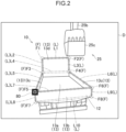
- Fig. 2 is a view of the transport vehicle 10 seen from the working machine 20 in the embodiment.
- the flat part 13 indicates a flat or substantially flat part of the container 12.
- the flat part 13 may have a flat shape or substantially flat shape as a whole.
- the flat part 13 may be uneven, or may have a gently curving surface.
- the flat part 13 has a floor 13a, a tail gate wall 13b, side gate walls 13c, and a guard wall 13d.
- the floor 13a defines a bottom surface (lower surface) of the container 12.
- the tail gate wall 13b defines a rear surface of the container 12 in a transport vehicle rearward portion of the container 12 and extends upward from the floor 13a in the transport vehicle rearward portion.
- the side gate walls 13c respectively define left and right surfaces of the container 12 and extend upward from left and right ends of the floor 13a.
- the guard wall 13d defines a front surface of the container 12 in a transport vehicle forward portion and extends from the floor 13a in the transport vehicle forward portion. The guard wall 13d extends upward further than the side gate walls 13c and further than the tail gate wall 13b.
- the working machine 20 performs a work (loading work) of loading a load object to the container 12.
- the working machine 20 may be configured to, for example, scoop the load object, or sandwich and grasp the load object.
- Examples of the working machine 20 include a construction machine that performs a construction work, e.g., a hydraulic excavator.
- the working machine 20 includes a lower traveling body 21, an upper slewing body 23, and an attachment 25.
- the lower traveling body 21 causes the working machine 20 to travel.
- the lower traveling body 21 includes, for example, a crawler.
- the upper slewing body 23 is slewably mounted on the lower traveling body 21.
- the upper slewing body 23 has a cab 23a.
- the attachment 25 transfers the load object.
- the attachment 25 has a boom 25a, an arm 25b, and a leading end attachment 25c.
- the boom 25a is tiltably attached to the upper slewing body 23 (rotatably upward and downward).
- the arm 25b is rotatably attached to the boom 25a (in a pulling or pushing manner).
- the leading end attachment 25c is provided on a distal end of the attachment 25 and rotatably attached to the arm 25b.
- the leading end attachment 25c may be a bucket to scoop the load object (e.g., soil and sand), or a device (e.g., grapple) to sandwich and grasp the load object.
- the container measurement system is a system for measuring three-dimensional information about the container 12.
- the term "three-dimensional information about the container 12" represents information including a three-dimensional position (three-dimensional coordinate) and a three-dimensional shape.
- the container measurement system measures a position, a direction, and a shape of the container 12 with respect to the working machine 20. As an example, a predetermined origin point or reference point is set in the working machine 20.
- Fig. 3 is a block diagram of the container measurement system 30.
- the container measurement system 30 includes a distance image acquisition part 40, a display (display device) 50, a controller 60, and a data storage part 70.
- the distance image acquisition part 40 acquires a distance image D showing the container 12 as shown in Fig. 2 .
- the distance image D includes distance information (depth information). Specifically, the distance image D corresponds to a distribution of distances respectively from measurement points around the working machine 20 to the origin point.
- the distance image acquisition part 40 is provided in the working machine 20.
- the distance image acquisition part 40 is arranged at such a position as to acquire the distance image D of the container 12 and a periphery of the container 12 when the working machine 20 performs the loading work.
- the distance image acquisition part 40 may be arranged or provided inside the cab 23a, may be arranged outside the cab 23a, or may be arranged on a top surface of the cab 23a as exemplified in Fig. 1 .
- the distance image acquisition part 40 may automatically follow the container 12 to acquire the distance image D of the container 12.
- the distance image acquisition part 40 has a two-dimensional information acquisition section 42 and a three-dimensional information acquisition section 43.
- the two-dimensional information acquisition section 42 acquires (captures) two-dimensional information (image) showing the container 12.
- the two-dimensional information acquisition section 42 is, for example, a camera.
- the three-dimensional information acquisition section 43 acquires three-dimensional information (point cloud data) about the container 12.
- the three-dimensional information acquisition section 43 measures a distance from the three-dimensional information acquisition section 43 to each component (to be described in detail later) of the container 12.
- the three-dimensional information acquisition section 43 may include LiDAR (Light Detection and Ranging, or laser Imaging Detection and Ranging), may include a stereo camera, or may include TOD (Time Of Flight) sensor.
- the display 50 may be provided in the operating compartment 11a of the transport vehicle 10, may be provided in the cab 23a of the working machine 20, or may be provided outside the transport vehicle 10 and outside the working machine 20.
- the controller 60 executes input and output of a signal, determination, computation like calculation, and storage of information.
- the controller 60 has an image processing part 61, a position coordinate estimation part 62, a three-dimensional coordinate acquisition part 63, a coordinate conversion part 64, a first superimposing part 65, and a feature point position detection part 66.
- the image processing part 61 preprocesses the image acquired by the two-dimensional information acquisition section 42.
- the preprocessing includes removing a noise from the image and emphasizing an edge in the image.
- the position coordinate estimation part 62 estimates a shape of the container 12 from the image preprocessed by the image processing part 61. Specifically, as shown in Fig. 2 , the position coordinate estimation part 62 extracts (recognizes, estimates) positions of feature points F (F1 to F8) in the image and positions of links L(L1 to L9) in the image. The position coordinate estimation part 62 extracts each feature point F and each link L by executing, for example, a program for extracting a specific shape from an image. For instance, the program adopts a deep learning technique. In this manner, the position coordinate estimation part 62 acquires two-dimensional information including the image showing the container 12, the position of the feature point F in the image, and the position of the link L in the image.
- each feature point F corresponds to a point on a corner of the flat part 13.
- Each link L represents a line connecting two feature points F to each other, and corresponds to, for example, a side line of the flat part 13.
- the positions of the feature points F include two positions (F1, F2) on upper ends of the guard wall 13d, two positions (F3, F4) on upper ends of the side gate walls 13c, 13c in the transport vehicle forward portion, and four positions (F5 to F8) on corners of the tail gate wall 13b.
- the position of the lower end of the guard wall 13d may be extracted as the feature point F (see Fig. 1 ).
- the positions of the links L include positions (L1 to L4) of four sides of a quadrangle in a portion of the guard wall 13d that is located at a higher position than the side gate walls 13c.
- the positions of the links L include positions (L5, L6) of upper sides of the side gate walls 13c and four sides (L7 to L10) of the tail gate wall 13b, specifically, four sides of a quadrangle substantially overlapping the tail gate wall 13b.
- the three-dimensional coordinate acquisition part 63 acquires a three-dimensional coordinate of each piece of the point cloud data captured by the three-dimensional information acquisition section 43.
- the coordinate conversion part 64 acquires a two-dimensional coordinate of each piece of the point cloud data through perspective projection transformation of the three-dimensional coordinate of each piece of the point cloud data.
- the coordinate system of the two-dimensional coordinate agrees with a coordinate system of the image acquired by the two-dimensional information acquisition section 42.
- the first superimposing part 65 superimposes the two-dimensional coordinate of each piece of the point cloud data acquired by the coordinate conversion part 64 and the shape of the container 12 estimated by the position coordinate estimation part 62 one on another. In this manner, a point corresponding to each feature point F shown in Fig. 2 is acquirable from the point cloud data.
- the two-dimensional coordinate of each piece of the point cloud data and the estimated shape of the container 12 may be superimposed one on another by using a coordinate system of a machine coordinate.
- the machine coordinate has an origin at a specific position in the working machine 20.
- the coordinate system of the two-dimensional coordinate of each piece of the point cloud data is set to agree with the coordinate system of the machine coordinate
- the coordinate system of the image acquired by the two-dimensional information acquisition section 42 is set to agree with the coordinate system of the machine coordinate (so that the positions of the systems are relative to each other).
- the feature point position detection part (calculation part) 66 detects (calculates) a three-dimensional coordinate of each feature point F and each link L shown in Fig. 2 . Specifically, the feature point position detection part 66 detects a three-dimensional coordinate of a point corresponding to a specific feature point F shown in Fig. 2 from point cloud data superimposed onto the shape of the container 12 by the first superimposing part 65 to calculate a three-dimensional coordinate of a corner of the flat part 13 corresponding to the position of the feature point F. As a result, three-dimensional information on a corresponding link L connecting the feature point F is also calculated. The calculation leads to acquisition of the three-dimensional information about the container 12 (specifically, the feature point F and the link L).
- Fig. 4 is an illustration of three-dimensional information about the container 12 detected by the feature point position detection part 66.
- the three-dimensional information has an error in the feature point F1 surrounded by a circular sign "o" among eight feature points F (F1 to F8). It is seen from this perspective that even use of the deep learning technique may fail to accurately extract the feature point on some occasions.
- the controller 60 has a container shape detection part 67, a container specifying part 68, a feature point correction part 69, a second superimposing part 71, a third superimposing part 72, and a display control part 73.
- the container shape detection part 67 detects a three-dimensional shape of the container 12 from the three-dimensional coordinate of the feature point F and the three-dimensional information on the link L each calculated by the feature point position detection part 66.
- the container shape detection part 67 checks each of the eight feature points F (F1 to F8) concerning the detected three-dimensional shape of the container 12. The container shape detection part 67 then adopts the detected three-dimensional shape of the container 12 when three or more feature points F respectively have correct three-dimensional coordinates. By contrast, the container shape detection part 67 avoids adopting the detected three-dimensional shape of the container 12 when less than three feature points F have correct three-dimensional coordinates. In this case, the feature point position detection part 66 detects (calculates) a three-dimensional coordinate of each feature point F and each link L again.
- FIG. 5 is an explanatory view of the way of checking each feature point.
- the feature point F1 is defined as a reference, and an inner product of a vector A from the feature point F1 to the feature point F2 and a vector B from the feature point F1 to the feature point F3 is obtained.
- An angle between the vectors is defined as "0" to determine whether cos ⁇ indicates zero.
- the three-dimensional coordinate of the feature point F1 is determined to be correct when the cos ⁇ indicates zero, and the three-dimensional coordinate of the feature point F1 is determined to be incorrect when the cos ⁇ does not indicate zero.
- the three-dimensional coordinate of each of the eight feature points F has an origin point set at an appropriate position of the working machine 20.
- the feature point F2 is defined as a reference, and an inner product of a vector C from the feature point F2 to the feature point F4 and a vector (-A) from the feature point F2 to the feature point F1 is obtained, the vector -A being in the opposite direction to the vector A.
- the aforementioned determination is made. The determination is made for each of the eight features F1 to F8.
- the data storage part (storage part) 70 stores three-dimensional shapes of various kinds of containers in advance.
- the container specifying part (specifying part) 68 specifies a kind of the container 12 subjected to the calculation on the basis of the calculated three-dimensional shape of the container 12 and the three-dimensional shapes of the various kinds of containers stored in the data storage part 70.
- the container specifying part 68 specifies the kind of the container by selecting a container having a three-dimensional shape closest to the calculated three-dimensional shape of the container 12 among the three-dimensional shapes of the various kinds of containers stored in the data storage part 70.
- the kind of the container 12 can be preferably specified by selecting a container having a three-dimensional shape closest to the calculated three-dimensional shape of the container 12.
- the feature point correction part (correction part) 69 corrects the calculated three-dimensional information about the container 12 on the basis of the three-dimensional shape of the specified kind of the container among the three-dimensional shapes of the various kinds of containers stored in the data storage part 70. As described above, even when the three-dimensional information about the container 12 calculated from the distance image has an error, correction of the three-dimensional information about the container 12 leads to a success in accurate calculation of the three-dimensional information about the container 12.
- the three-dimensional information about the container 12 is adoptable for various controls.
- the information is adoptable for automatic operation of the working machine 20 or adoptable for assistive operation of the working machine 20.
- the information is further adoptable for a control of avoiding a collision between the working machine 20 and the container 12, a control of automatically changing the positions of the working machine 20 and container 12 relative to each other, and a control of notifying an operator of the positions of the working machine 20 and the container 12 relative to each other.
- the information is adoptable for calculation of a locus of the leading end attachment 25c from a current position of the leading end attachment 25c to a position (discharge position, e.g., soil discharge position) for discharging the load object.
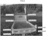
- the second superimposing part (superimposing part) 71 superimposes the corrected three-dimensional information about the container 12 onto the image preprocessed by the image processing part 61 to generate a first superimposed image.
- an AR marker 80 is provided as a marking member on a corner of the flat part 13 that corresponds to the position of the feature point F5.
- the second superimposing part 71 sets the image at the corrected three-dimensional position of the container 12 with reference to the AR marker 80.
- the set image and position are superimposed to generate the first superimposed image.
- the marking member for the setting may be a light (e.g., LED) to be tuned on.
- the image is set to the corrected three-dimensional position of the container 12 with reference to the AR marker 80.
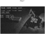
- the third superimposing part (superimposing part) 72 superimposes the corrected three-dimensional information about the container 12 onto the point cloud data acquired by the three-dimensional coordinate acquisition part 63 to generate a second superimposed image.
- the third superimposing part 72 superimposes the corrected three-dimensional information about the container 12 onto the point cloud data to generate the second superimposed image after setting the point cloud data at the position of the corrected three-dimensional information.
- the setting may be executed with reference to the AR marker.
- the display control part 73 causes the display 50 to display the first superimposed image generated by the second superimposing part 71.
- Fig. 6 shows an example of the first superimposed image.
- the display control part 73 further causes the display 50 to display the second superimposed image generated by the third superimposing part 72.
- Fig. 7 shows an example of the second superimposed image.
- the operator when the operator remotely manipulates the working machine 20, the operator can recognize a depth to the container 12 by visually confirming the first superimposed image and the second superimposed image.
- Fig. 8 is a flowchart of a container measurement process. Next, the operation of the container measurement system 30 will be described with reference to Fig. 8 .
- the controller 60 acquires an image from the two-dimensional information acquisition section 42 (step S1), and preprocesses the acquired image (step S2).
- the controller 60 estimates a shape of the container 12 from the preprocessed image by using a deep learning technique (step S3).
- the controller 60 acquires point cloud data from the three-dimensional information acquisition section 43 (step S4), and acquires a three-dimensional coordinate of each piece of the acquired point cloud data (step S5).
- the controller 60 then acquires a two-dimensional coordinate of each piece of the point cloud data through perspective projection transformation of the three-dimensional coordinate of each piece of the point cloud data (step S6).
- the controller 60 superimposes the two-dimensional coordinate of each piece of the point cloud data and the shape of the container 12 one on another (step S7).
- the controller 60 subsequently calculates a three-dimensional coordinate of each feature point F and each link L (step S8).
- the controller 60 detects a three-dimensional shape of the container 12 from the three-dimensional coordinate of the feature point F and the three-dimensional information on the link L (step S9).
- the controller 60 checks each of the eight feature points F (F1 to F8) (step S10). The controller 60 subsequently determines whether three or more correct feature points F respectively have correct three-dimensional coordinates (step S11). When determining that less than three correct feature points have correct three-dimensional coordinates in step S11 (NO in step S11), the controller 60 returns to step S8 to calculate a three-dimensional coordinate of each feature point F and each link L again.
- step S11 when determining that three or more correct feature points respectively have the three-dimensional coordinates in step S11 (YES in step S11), the controller 60 specifies a kind of the container 12 on the basis of the calculated three-dimensional shape of the container 12 and three-dimensional shapes of various kinds of containers stored in the data storage part 70 (step S 12). The controller 60 then corrects, on the basis of the three-dimensional shape of the specified kind of the container, the calculated three-dimensional information about the container 12 (step S13).
- the controller 60 generates a first superimposed image and a second superimposed image (step S14). Specifically, the controller 60 superimposes the corrected three-dimensional information about the container 12 onto the preprocessed image to generate the first superimposed image. The controller 60 further superimposes the corrected three-dimensional information about the container 12 onto the acquired point cloud data to generate the second superimposed image.
- controller 60 causes the display 50 to display the first superimposed image and the second superimposed image (step S15). This process is then finished.
- three-dimensional information including a three-dimensional position and a three-dimensional shape of the container 12 is calculated on the basis of an acquired distance image of the container 12. Further, a kind of the container 12 subjected to the calculation is specified on the basis of the calculated three-dimensional shape of the container 12 and three-dimensional shapes of various kinds of containers stored in the data storage part 70. When the kind of the container 12 is specified, the calculated three-dimensional information about the container 12 is corrected on the basis of the three-dimensional shape of the specified kind of the container. As described above, even when the three-dimensional information about the container 12 calculated from the distance image of the container 12 has an error, correction of the three-dimensional information about the container 12 leads to a success in accurate calculation of the three-dimensional information about the container 12.
- the kind of the container 12 subjected to the calculation is specified by selecting a container having a three-dimensional shape closest to the calculated three-dimensional shape of the container 12 among the three-dimensional shapes of the various kinds of containers stored in the data storage part 70.
- the three-dimensional information about the container 12 calculated from the distance image of the container 12 has an error
- no container having a three-dimensional shape matching the three-dimensional shape of the container 12 calculated from the distance image may be found among the three-dimensional shapes of the various kinds of containers stored in the data storage part 70.
- selecting a container having a three-dimensional shape closest to the calculated three-dimensional shape of the container 12 succeeds in preferably specifying the kind of the container 12 subjected to the calculation.
- the corrected three-dimensional information about the container 12 is superimposed onto the distance image to generate a superimposed image (a first superimposed image, a second superimposed image) after the acquired distance image of the container 12 is set at the corrected three-dimensional position of the container 12. Then, the display 50 displays the superimposed image thereon. For instance, when the operator remotely manipulates the working machine 20, the operator can recognize a depth to the container 12 by visually confirming the superimposed image.
- the distance image of the container 12 is set to the corrected three-dimensional position of the container 12 with reference to the marking member (the AR marker 80) provided to the container 12. This consequently attains improvement in the accuracy of the setting and achieves a reduction in the burden required for the setting.
- the present invention provides a container measurement system.
- the container measurement system includes: a distance image acquisition part provided in a working machine that performs a loading work to a container for acquiring a distance image of the container; a calculation part that calculates, on the basis of the acquired distance image, three-dimensional information including a three-dimensional position and a three-dimensional shape of the container; a storage part that stores three-dimensional shapes of various kinds of containers; a specifying part that specifies a kind of the container subjected to the calculation on the basis of the three-dimensional shape of the container calculated by the calculation part and the three-dimensional shapes of the various kinds of containers stored in the storage part; and a correction part that corrects, on the basis of the three-dimensional shape of the kind of the container specified by the specifying part, the three-dimensional information about the container calculated by the calculation part.
- the specifying part may specify the kind of the container subjected to the calculation by selecting a container having a three-dimensional shape closest to the three-dimensional shape of the container calculated by the calculation part among the three-dimensional shapes of the various kinds of containers stored in the storage part.
- the configuration may further include: a display device; a superimposing part that superimposes the corrected three-dimensional information about the container onto the distance image to generate a superimposed image after setting the distance image of the container acquired by the distance image acquisition part at a three-dimensional position of the container corrected by the correction part; and a display control part that causes the display device to display the superimposed image.
- the configuration may further include a marker provided on the container so as to be captured in the distance image.
- the superimposing part may set the distance image at the corrected three-dimensional position of the container with reference to the marker.
- three-dimensional information including a three-dimensional position and a three-dimensional shape of a container is calculated on the basis of an acquired distance image of the container. Further, a kind of the container subjected to the calculation is specified on the basis of the calculated three-dimensional shape of the container and three-dimensional shapes of various kinds of containers stored in a storage part. When the kind of the container is specified, the calculated three-dimensional information about the container is corrected on the basis of the three-dimensional shape of the specified kind of the container. Conclusively, even when the three-dimensional information about the container calculated from the distance image of the container has an error, correction of the three-dimensional information about the container leads to a success in accurate calculation of the three-dimensional information about the container.
Landscapes
- Engineering & Computer Science (AREA)
- Physics & Mathematics (AREA)
- General Physics & Mathematics (AREA)
- Theoretical Computer Science (AREA)
- Computer Vision & Pattern Recognition (AREA)
- Multimedia (AREA)
- Quality & Reliability (AREA)
- Mining & Mineral Resources (AREA)
- Civil Engineering (AREA)
- General Engineering & Computer Science (AREA)
- Structural Engineering (AREA)
- Length Measuring Devices By Optical Means (AREA)
- Component Parts Of Construction Machinery (AREA)
Abstract
Description
- The present invention relates to a container measurement system for calculating three-dimensional information about a container.
- For instance,
Patent Literature 1 describes a technology of calculating three-dimensional information about a container. The technology described in the literature includes photographing four feature points of the container by a camera and calculating a three-dimensional position for each of the feature points. - Patent Literature 1:
Japanese Unexamined Patent Publication No. 2000-064359 - The technology described in
Patent Literature 1 faces a difficulty in stably calculating the three-dimensional information on a feature point when a camera fails to appropriately photograph the feature point. As a result, it is difficult to stably calculate three-dimensional information about the container. - Under the circumstances, a possible way is to calculate three-dimensional information on a feature point by extracting the feature point with use of a publicly known deep learning technique even when the camera fails to appropriately photograph the feature point as described above. However, even use of the deep learning technique may fail to accurately extract the feature point on some occasions.
- An object of the present invention is to provide a container measurement system that enables accurate calculation of three-dimensional information about a container.
- The present invention provides a container measurement system. The container measurement system includes: a distance image acquisition part provided in a working machine that performs a loading work to a container for acquiring a distance image of the container; a calculation part that calculates, on the basis of the acquired distance image, three-dimensional information including a three-dimensional position and a three-dimensional shape of the container; a storage part that stores three-dimensional shapes of various kinds of containers; a specifying part that specifies a kind of the container subjected to the calculation on the basis of the three-dimensional shape of the container calculated by the calculation part and the three-dimensional shapes of the various kinds of containers stored in the storage part; and a correction part that corrects, on the basis of the three-dimensional shape of the kind of the container specified by the specifying part, the three-dimensional information about the container calculated by the calculation part.
-
-
Fig. 1 is a side view of a transport vehicle and a working machine in an embodiment of the present invention. -
Fig. 2 is a view of the transport vehicle seen from the working machine in the embodiment of the present invention. -
Fig. 3 is a block diagram of a container measurement system according to the embodiment of the present invention. -
Fig. 4 is an illustration of three-dimensional information about a container in the embodiment of the present invention. -
Fig. 5 is an explanatory view of a way of checking a feature point in the embodiment of the present invention. -
Fig. 6 is an illustration of a first superimposed image by the container measurement system according to the embodiment of the present invention. -
Fig. 7 is an illustration of a second superimposed image by the container measurement system according to the embodiment of the present invention. -
Fig. 8 is a flowchart of a container measurement process in the embodiment of the present invention. - Hereinafter, a preferable embodiment of the present invention will be described with reference to the accompanying drawings.
- A container measurement system in an embodiment of the present invention aims at calculating three-dimensional information about a container.
Fig. 1 is a side view of atransport vehicle 10 and aworking machine 20 in the embodiment. As shown inFig. 1 , thetransport vehicle 10 includes acontainer 12. Thetransport vehicle 10 is intended for transporting an object (load object) loaded by theworking machine 20, and may be a dump truck or another truck. - The
transport vehicle 10 includes amain body 11 and thecontainer 12. Themain body 11 is travelable on the ground and supports thecontainer 12. Themain body 11 has anoperating compartment 11a. Thecontainer 12 is located in the rear of theoperating compartment 11a in thetransport vehicle 10. - The
container 12 serves as a load bed of thetransport vehicle 10. Thecontainer 12 has, for example, a shape like a box shape without a cover (seeFig. 2 ). Thecontainer 12 has aflat part 13. Thecontainer 12 accommodates the load object. The load object to be accommodated in thecontainer 12 may be, for example, soil and sand, or waste or industrial waste. Thecontainer 12 may be movable with respect to themain body 11, or may be fixed to themain body 11. Thecontainer 12 may be, for example, a container directly arrangeable on the ground in place of the load bed of thetransport vehicle 10. - Hereinafter, directions concerning the
transport vehicle 10 are defined as follows, specifically, a direction from theoperating compartment 11a to thecontainer 12 is defined as "transport vehicle rearward direction", and a direction from thecontainer 12 to theoperating compartment 11a is defined as "transport vehicle forward direction". -
Fig. 2 is a view of thetransport vehicle 10 seen from theworking machine 20 in the embodiment. As shown inFig. 2 , theflat part 13 indicates a flat or substantially flat part of thecontainer 12. Theflat part 13 may have a flat shape or substantially flat shape as a whole. Theflat part 13 may be uneven, or may have a gently curving surface. - The
flat part 13 has afloor 13a, atail gate wall 13b,side gate walls 13c, and aguard wall 13d. Thefloor 13a defines a bottom surface (lower surface) of thecontainer 12. Thetail gate wall 13b defines a rear surface of thecontainer 12 in a transport vehicle rearward portion of thecontainer 12 and extends upward from thefloor 13a in the transport vehicle rearward portion. Theside gate walls 13c respectively define left and right surfaces of thecontainer 12 and extend upward from left and right ends of thefloor 13a. Theguard wall 13d defines a front surface of thecontainer 12 in a transport vehicle forward portion and extends from thefloor 13a in the transport vehicle forward portion. Theguard wall 13d extends upward further than theside gate walls 13c and further than thetail gate wall 13b. - As shown in
Fig. 1 , theworking machine 20 performs a work (loading work) of loading a load object to thecontainer 12. Theworking machine 20 may be configured to, for example, scoop the load object, or sandwich and grasp the load object. Examples of theworking machine 20 include a construction machine that performs a construction work, e.g., a hydraulic excavator. - The working
machine 20 includes alower traveling body 21, anupper slewing body 23, and anattachment 25. The lower travelingbody 21 causes the workingmachine 20 to travel. The lowertraveling body 21 includes, for example, a crawler. Theupper slewing body 23 is slewably mounted on the lower travelingbody 21. Theupper slewing body 23 has acab 23a. - The
attachment 25 transfers the load object. Theattachment 25 has aboom 25a, anarm 25b, and a leadingend attachment 25c. Theboom 25a is tiltably attached to the upper slewing body 23 (rotatably upward and downward). Thearm 25b is rotatably attached to theboom 25a (in a pulling or pushing manner). Theleading end attachment 25c is provided on a distal end of theattachment 25 and rotatably attached to thearm 25b. Theleading end attachment 25c may be a bucket to scoop the load object (e.g., soil and sand), or a device (e.g., grapple) to sandwich and grasp the load object. - The container measurement system is a system for measuring three-dimensional information about the
container 12. The term "three-dimensional information about thecontainer 12" represents information including a three-dimensional position (three-dimensional coordinate) and a three-dimensional shape. The container measurement system measures a position, a direction, and a shape of thecontainer 12 with respect to the workingmachine 20. As an example, a predetermined origin point or reference point is set in the workingmachine 20. -
Fig. 3 is a block diagram of thecontainer measurement system 30. As shown inFig. 3 , thecontainer measurement system 30 includes a distanceimage acquisition part 40, a display (display device) 50, acontroller 60, and adata storage part 70. - The distance
image acquisition part 40 acquires a distance image D showing thecontainer 12 as shown inFig. 2 . The distance image D includes distance information (depth information). Specifically, the distance image D corresponds to a distribution of distances respectively from measurement points around the workingmachine 20 to the origin point. The distanceimage acquisition part 40 is provided in the workingmachine 20. The distanceimage acquisition part 40 is arranged at such a position as to acquire the distance image D of thecontainer 12 and a periphery of thecontainer 12 when the workingmachine 20 performs the loading work. For instance, the distanceimage acquisition part 40 may be arranged or provided inside thecab 23a, may be arranged outside thecab 23a, or may be arranged on a top surface of thecab 23a as exemplified inFig. 1 . The distanceimage acquisition part 40 may automatically follow thecontainer 12 to acquire the distance image D of thecontainer 12. - As shown in
Fig. 3 , the distanceimage acquisition part 40 has a two-dimensionalinformation acquisition section 42 and a three-dimensionalinformation acquisition section 43. The two-dimensionalinformation acquisition section 42 acquires (captures) two-dimensional information (image) showing thecontainer 12. The two-dimensionalinformation acquisition section 42 is, for example, a camera. - The three-dimensional
information acquisition section 43 acquires three-dimensional information (point cloud data) about thecontainer 12. The three-dimensionalinformation acquisition section 43 measures a distance from the three-dimensionalinformation acquisition section 43 to each component (to be described in detail later) of thecontainer 12. Specifically, for instance, the three-dimensionalinformation acquisition section 43 may include LiDAR (Light Detection and Ranging, or laser Imaging Detection and Ranging), may include a stereo camera, or may include TOD (Time Of Flight) sensor. - The
display 50 may be provided in theoperating compartment 11a of thetransport vehicle 10, may be provided in thecab 23a of the workingmachine 20, or may be provided outside thetransport vehicle 10 and outside the workingmachine 20. - The
controller 60 executes input and output of a signal, determination, computation like calculation, and storage of information. Thecontroller 60 has animage processing part 61, a position coordinateestimation part 62, a three-dimensional coordinateacquisition part 63, a coordinateconversion part 64, a first superimposingpart 65, and a feature pointposition detection part 66. - The
image processing part 61 preprocesses the image acquired by the two-dimensionalinformation acquisition section 42. The preprocessing includes removing a noise from the image and emphasizing an edge in the image. - The position coordinate
estimation part 62 estimates a shape of thecontainer 12 from the image preprocessed by theimage processing part 61. Specifically, as shown inFig. 2 , the position coordinateestimation part 62 extracts (recognizes, estimates) positions of feature points F (F1 to F8) in the image and positions of links L(L1 to L9) in the image. The position coordinateestimation part 62 extracts each feature point F and each link L by executing, for example, a program for extracting a specific shape from an image. For instance, the program adopts a deep learning technique. In this manner, the position coordinateestimation part 62 acquires two-dimensional information including the image showing thecontainer 12, the position of the feature point F in the image, and the position of the link L in the image. - As shown in
Fig. 2 , each feature point F corresponds to a point on a corner of theflat part 13. Each link L represents a line connecting two feature points F to each other, and corresponds to, for example, a side line of theflat part 13. In the example shown inFig. 2 , the positions of the feature points F include two positions (F1, F2) on upper ends of theguard wall 13d, two positions (F3, F4) on upper ends of theside gate walls tail gate wall 13b. For instance, when a lower end of theguard wall 13d is reflected in the image, the position of the lower end of theguard wall 13d may be extracted as the feature point F (seeFig. 1 ). - In the example shown in
Fig. 2 , the positions of the links L include positions (L1 to L4) of four sides of a quadrangle in a portion of theguard wall 13d that is located at a higher position than theside gate walls 13c. The positions of the links L include positions (L5, L6) of upper sides of theside gate walls 13c and four sides (L7 to L10) of thetail gate wall 13b, specifically, four sides of a quadrangle substantially overlapping thetail gate wall 13b. - Referring back to
Fig. 3 , the three-dimensional coordinateacquisition part 63 acquires a three-dimensional coordinate of each piece of the point cloud data captured by the three-dimensionalinformation acquisition section 43. The coordinateconversion part 64 acquires a two-dimensional coordinate of each piece of the point cloud data through perspective projection transformation of the three-dimensional coordinate of each piece of the point cloud data. The coordinate system of the two-dimensional coordinate agrees with a coordinate system of the image acquired by the two-dimensionalinformation acquisition section 42. - The first superimposing
part 65 superimposes the two-dimensional coordinate of each piece of the point cloud data acquired by the coordinateconversion part 64 and the shape of thecontainer 12 estimated by the position coordinateestimation part 62 one on another. In this manner, a point corresponding to each feature point F shown inFig. 2 is acquirable from the point cloud data. - The two-dimensional coordinate of each piece of the point cloud data and the estimated shape of the
container 12 may be superimposed one on another by using a coordinate system of a machine coordinate. The machine coordinate has an origin at a specific position in the workingmachine 20. In use of the coordinate system of the machine coordinate, the coordinate system of the two-dimensional coordinate of each piece of the point cloud data is set to agree with the coordinate system of the machine coordinate, and the coordinate system of the image acquired by the two-dimensionalinformation acquisition section 42 is set to agree with the coordinate system of the machine coordinate (so that the positions of the systems are relative to each other). - The feature point position detection part (calculation part) 66 detects (calculates) a three-dimensional coordinate of each feature point F and each link L shown in
Fig. 2 . Specifically, the feature pointposition detection part 66 detects a three-dimensional coordinate of a point corresponding to a specific feature point F shown inFig. 2 from point cloud data superimposed onto the shape of thecontainer 12 by the first superimposingpart 65 to calculate a three-dimensional coordinate of a corner of theflat part 13 corresponding to the position of the feature point F. As a result, three-dimensional information on a corresponding link L connecting the feature point F is also calculated. The calculation leads to acquisition of the three-dimensional information about the container 12 (specifically, the feature point F and the link L). -
Fig. 4 is an illustration of three-dimensional information about thecontainer 12 detected by the feature pointposition detection part 66. In the example shown inFig. 4 , the three-dimensional information has an error in the feature point F1 surrounded by a circular sign "o" among eight feature points F (F1 to F8). It is seen from this perspective that even use of the deep learning technique may fail to accurately extract the feature point on some occasions. - As shown in
Fig. 3 , thecontroller 60 has a containershape detection part 67, acontainer specifying part 68, a featurepoint correction part 69, asecond superimposing part 71, a third superimposingpart 72, and adisplay control part 73. - The container
shape detection part 67 detects a three-dimensional shape of thecontainer 12 from the three-dimensional coordinate of the feature point F and the three-dimensional information on the link L each calculated by the feature pointposition detection part 66. - The container
shape detection part 67 checks each of the eight feature points F (F1 to F8) concerning the detected three-dimensional shape of thecontainer 12. The containershape detection part 67 then adopts the detected three-dimensional shape of thecontainer 12 when three or more feature points F respectively have correct three-dimensional coordinates. By contrast, the containershape detection part 67 avoids adopting the detected three-dimensional shape of thecontainer 12 when less than three feature points F have correct three-dimensional coordinates. In this case, the feature pointposition detection part 66 detects (calculates) a three-dimensional coordinate of each feature point F and each link L again. - A way of checking each of the eight feature points F will be described below.
Fig. 5 is an explanatory view of the way of checking each feature point. As shown inFig. 5 , the feature point F1 is defined as a reference, and an inner product of a vector A from the feature point F1 to the feature point F2 and a vector B from the feature point F1 to the feature point F3 is obtained. An angle between the vectors is defined as "0" to determine whether cos θ indicates zero. - The three-dimensional coordinate of the feature point F1 is determined to be correct when the cos θ indicates zero, and the three-dimensional coordinate of the feature point F1 is determined to be incorrect when the cos θ does not indicate zero. Here, the three-dimensional coordinate of each of the eight feature points F has an origin point set at an appropriate position of the working
machine 20. - Next, the feature point F2 is defined as a reference, and an inner product of a vector C from the feature point F2 to the feature point F4 and a vector (-A) from the feature point F2 to the feature point F1 is obtained, the vector -A being in the opposite direction to the vector A. Similarly, the aforementioned determination is made. The determination is made for each of the eight features F1 to F8.
- Referring back to
Fig. 3 , the data storage part (storage part) 70 stores three-dimensional shapes of various kinds of containers in advance. The container specifying part (specifying part) 68 specifies a kind of thecontainer 12 subjected to the calculation on the basis of the calculated three-dimensional shape of thecontainer 12 and the three-dimensional shapes of the various kinds of containers stored in thedata storage part 70. - The
container specifying part 68 specifies the kind of the container by selecting a container having a three-dimensional shape closest to the calculated three-dimensional shape of thecontainer 12 among the three-dimensional shapes of the various kinds of containers stored in thedata storage part 70. - In a case where the three-dimensional information about the container calculated from the distance image has an error, no container having a three-dimensional shape matching the three-dimensional shape of the
container 12 calculated from the distance image may be found among the three-dimensional shapes of the various kinds of containers stored in thedata storage part 70. Even in this case, the kind of thecontainer 12 can be preferably specified by selecting a container having a three-dimensional shape closest to the calculated three-dimensional shape of thecontainer 12. - The feature point correction part (correction part) 69 corrects the calculated three-dimensional information about the
container 12 on the basis of the three-dimensional shape of the specified kind of the container among the three-dimensional shapes of the various kinds of containers stored in thedata storage part 70. As described above, even when the three-dimensional information about thecontainer 12 calculated from the distance image has an error, correction of the three-dimensional information about thecontainer 12 leads to a success in accurate calculation of the three-dimensional information about thecontainer 12. - The three-dimensional information about the
container 12 is adoptable for various controls. For instance, the information is adoptable for automatic operation of the workingmachine 20 or adoptable for assistive operation of the workingmachine 20. The information is further adoptable for a control of avoiding a collision between the workingmachine 20 and thecontainer 12, a control of automatically changing the positions of the workingmachine 20 andcontainer 12 relative to each other, and a control of notifying an operator of the positions of the workingmachine 20 and thecontainer 12 relative to each other. In addition, the information is adoptable for calculation of a locus of theleading end attachment 25c from a current position of theleading end attachment 25c to a position (discharge position, e.g., soil discharge position) for discharging the load object. - The second superimposing part (superimposing part) 71 superimposes the corrected three-dimensional information about the
container 12 onto the image preprocessed by theimage processing part 61 to generate a first superimposed image. As shown inFig. 2 , anAR marker 80 is provided as a marking member on a corner of theflat part 13 that corresponds to the position of the feature point F5. Thesecond superimposing part 71 sets the image at the corrected three-dimensional position of thecontainer 12 with reference to theAR marker 80. The set image and position are superimposed to generate the first superimposed image. The marking member for the setting may be a light (e.g., LED) to be tuned on. - In this manner, the image is set to the corrected three-dimensional position of the
container 12 with reference to theAR marker 80. This consequently attains improvement in the accuracy of the setting and achieves a reduction in the burden required for the setting. - Referring back to
Fig. 3 , the third superimposing part (superimposing part) 72 superimposes the corrected three-dimensional information about thecontainer 12 onto the point cloud data acquired by the three-dimensional coordinateacquisition part 63 to generate a second superimposed image. Thethird superimposing part 72 superimposes the corrected three-dimensional information about thecontainer 12 onto the point cloud data to generate the second superimposed image after setting the point cloud data at the position of the corrected three-dimensional information. The setting may be executed with reference to the AR marker. - The
display control part 73 causes thedisplay 50 to display the first superimposed image generated by the second superimposingpart 71.Fig. 6 shows an example of the first superimposed image. Thedisplay control part 73 further causes thedisplay 50 to display the second superimposed image generated by the third superimposingpart 72.Fig. 7 shows an example of the second superimposed image. - For instance, when the operator remotely manipulates the working
machine 20, the operator can recognize a depth to thecontainer 12 by visually confirming the first superimposed image and the second superimposed image. -
Fig. 8 is a flowchart of a container measurement process. Next, the operation of thecontainer measurement system 30 will be described with reference toFig. 8 . - First, the
controller 60 acquires an image from the two-dimensional information acquisition section 42 (step S1), and preprocesses the acquired image (step S2). Thecontroller 60 then estimates a shape of thecontainer 12 from the preprocessed image by using a deep learning technique (step S3). - Simultaneously with steps S1 to S3, the
controller 60 acquires point cloud data from the three-dimensional information acquisition section 43 (step S4), and acquires a three-dimensional coordinate of each piece of the acquired point cloud data (step S5). Thecontroller 60 then acquires a two-dimensional coordinate of each piece of the point cloud data through perspective projection transformation of the three-dimensional coordinate of each piece of the point cloud data (step S6). - Subsequently, the
controller 60 superimposes the two-dimensional coordinate of each piece of the point cloud data and the shape of thecontainer 12 one on another (step S7). Thecontroller 60 subsequently calculates a three-dimensional coordinate of each feature point F and each link L (step S8). Thecontroller 60 then detects a three-dimensional shape of thecontainer 12 from the three-dimensional coordinate of the feature point F and the three-dimensional information on the link L (step S9). - Next, the
controller 60 checks each of the eight feature points F (F1 to F8) (step S10). Thecontroller 60 subsequently determines whether three or more correct feature points F respectively have correct three-dimensional coordinates (step S11). When determining that less than three correct feature points have correct three-dimensional coordinates in step S11 (NO in step S11), thecontroller 60 returns to step S8 to calculate a three-dimensional coordinate of each feature point F and each link L again. - By contrast, when determining that three or more correct feature points respectively have the three-dimensional coordinates in step S11 (YES in step S11), the
controller 60 specifies a kind of thecontainer 12 on the basis of the calculated three-dimensional shape of thecontainer 12 and three-dimensional shapes of various kinds of containers stored in the data storage part 70 (step S 12). Thecontroller 60 then corrects, on the basis of the three-dimensional shape of the specified kind of the container, the calculated three-dimensional information about the container 12 (step S13). - Next, the
controller 60 generates a first superimposed image and a second superimposed image (step S14). Specifically, thecontroller 60 superimposes the corrected three-dimensional information about thecontainer 12 onto the preprocessed image to generate the first superimposed image. Thecontroller 60 further superimposes the corrected three-dimensional information about thecontainer 12 onto the acquired point cloud data to generate the second superimposed image. - Subsequently, the
controller 60 causes thedisplay 50 to display the first superimposed image and the second superimposed image (step S15). This process is then finished. - As described heretofore, in the
container measurement system 30 according to the embodiment, three-dimensional information including a three-dimensional position and a three-dimensional shape of thecontainer 12 is calculated on the basis of an acquired distance image of thecontainer 12. Further, a kind of thecontainer 12 subjected to the calculation is specified on the basis of the calculated three-dimensional shape of thecontainer 12 and three-dimensional shapes of various kinds of containers stored in thedata storage part 70. When the kind of thecontainer 12 is specified, the calculated three-dimensional information about thecontainer 12 is corrected on the basis of the three-dimensional shape of the specified kind of the container. As described above, even when the three-dimensional information about thecontainer 12 calculated from the distance image of thecontainer 12 has an error, correction of the three-dimensional information about thecontainer 12 leads to a success in accurate calculation of the three-dimensional information about thecontainer 12. - The kind of the
container 12 subjected to the calculation is specified by selecting a container having a three-dimensional shape closest to the calculated three-dimensional shape of thecontainer 12 among the three-dimensional shapes of the various kinds of containers stored in thedata storage part 70. In a case where the three-dimensional information about thecontainer 12 calculated from the distance image of thecontainer 12 has an error, no container having a three-dimensional shape matching the three-dimensional shape of thecontainer 12 calculated from the distance image may be found among the three-dimensional shapes of the various kinds of containers stored in thedata storage part 70. Even in this case, selecting a container having a three-dimensional shape closest to the calculated three-dimensional shape of thecontainer 12 succeeds in preferably specifying the kind of thecontainer 12 subjected to the calculation. - The corrected three-dimensional information about the
container 12 is superimposed onto the distance image to generate a superimposed image (a first superimposed image, a second superimposed image) after the acquired distance image of thecontainer 12 is set at the corrected three-dimensional position of thecontainer 12. Then, thedisplay 50 displays the superimposed image thereon. For instance, when the operator remotely manipulates the workingmachine 20, the operator can recognize a depth to thecontainer 12 by visually confirming the superimposed image. - The distance image of the
container 12 is set to the corrected three-dimensional position of thecontainer 12 with reference to the marking member (the AR marker 80) provided to thecontainer 12. This consequently attains improvement in the accuracy of the setting and achieves a reduction in the burden required for the setting. - The embodiment of the present invention is described heretofore, but the embodiment is merely described as a detailed example of the present invention without particularly limiting the present invention. It is the matter of design choice for changes in the details of the configuration. Furthermore, the operations and effects described in the embodiments of the present invention are merely listed as optimal operations and effects attained by the present invention, and thus should not be limited thereto.
- The present invention provides a container measurement system. The container measurement system includes: a distance image acquisition part provided in a working machine that performs a loading work to a container for acquiring a distance image of the container; a calculation part that calculates, on the basis of the acquired distance image, three-dimensional information including a three-dimensional position and a three-dimensional shape of the container; a storage part that stores three-dimensional shapes of various kinds of containers; a specifying part that specifies a kind of the container subjected to the calculation on the basis of the three-dimensional shape of the container calculated by the calculation part and the three-dimensional shapes of the various kinds of containers stored in the storage part; and a correction part that corrects, on the basis of the three-dimensional shape of the kind of the container specified by the specifying part, the three-dimensional information about the container calculated by the calculation part.
- In the configuration, the specifying part may specify the kind of the container subjected to the calculation by selecting a container having a three-dimensional shape closest to the three-dimensional shape of the container calculated by the calculation part among the three-dimensional shapes of the various kinds of containers stored in the storage part.
- The configuration may further include: a display device; a superimposing part that superimposes the corrected three-dimensional information about the container onto the distance image to generate a superimposed image after setting the distance image of the container acquired by the distance image acquisition part at a three-dimensional position of the container corrected by the correction part; and a display control part that causes the display device to display the superimposed image.
- The configuration may further include a marker provided on the container so as to be captured in the distance image. The superimposing part may set the distance image at the corrected three-dimensional position of the container with reference to the marker.
- According to the present invention, three-dimensional information including a three-dimensional position and a three-dimensional shape of a container is calculated on the basis of an acquired distance image of the container. Further, a kind of the container subjected to the calculation is specified on the basis of the calculated three-dimensional shape of the container and three-dimensional shapes of various kinds of containers stored in a storage part. When the kind of the container is specified, the calculated three-dimensional information about the container is corrected on the basis of the three-dimensional shape of the specified kind of the container. Conclusively, even when the three-dimensional information about the container calculated from the distance image of the container has an error, correction of the three-dimensional information about the container leads to a success in accurate calculation of the three-dimensional information about the container.
Claims (4)
- A container measurement system, comprising:a distance image acquisition part provided in a working machine that performs a loading work to a container for acquiring a distance image of the container;a calculation part that calculates, on the basis of the acquired distance image, three-dimensional information including a three-dimensional position and a three-dimensional shape of the container;a storage part that stores three-dimensional shapes of various kinds of containers;a specifying part that specifies a kind of the container subjected to the calculation on the basis of the three-dimensional shape of the container calculated by the calculation part and the three-dimensional shapes of the various kinds of containers stored in the storage part; anda correction part that corrects, on the basis of the three-dimensional shape of the kind of the container specified by the specifying part, the three-dimensional information about the container calculated by the calculation part.
- The container measurement system according to claim 1, wherein the specifying part specifies the kind of the container subjected to the calculation by selecting a container having a three-dimensional shape closest to the three-dimensional shape of the container calculated by the calculation part among the three-dimensional shapes of the various kinds of containers stored in the storage part.
- The container measurement system according to claim 1 or 2, further comprising:a display device;a superimposing part that superimposes the corrected three-dimensional information about the container onto the distance image to generate a superimposed image after setting the distance image of the container acquired by the distance image acquisition part at a three-dimensional position of the container corrected by the correction part; anda display control part that causes the display device to display the superimposed image.
- The container measurement system according to claim 3, further comprising a marker provided on the container so as to be captured in the distance image, wherein
the superimposing part sets the distance image at the corrected three-dimensional position of the container with reference to the marker.
Applications Claiming Priority (2)
| Application Number | Priority Date | Filing Date | Title |
|---|---|---|---|
| JP2021036652A JP7452473B2 (en) | 2021-03-08 | 2021-03-08 | Container measuring system |
| PCT/JP2021/044236 WO2022190484A1 (en) | 2021-03-08 | 2021-12-02 | Container measurement system |
Publications (2)
| Publication Number | Publication Date |
|---|---|
| EP4269710A1 true EP4269710A1 (en) | 2023-11-01 |
| EP4269710A4 EP4269710A4 (en) | 2024-08-21 |
Family
ID=83227837
Family Applications (1)
| Application Number | Title | Priority Date | Filing Date |
|---|---|---|---|
| EP21930330.2A Pending EP4269710A4 (en) | 2021-03-08 | 2021-12-02 | CONTAINER MEASURING SYSTEM |
Country Status (5)
| Country | Link |
|---|---|
| US (1) | US20240112459A1 (en) |
| EP (1) | EP4269710A4 (en) |
| JP (1) | JP7452473B2 (en) |
| CN (1) | CN116761919B (en) |
| WO (1) | WO2022190484A1 (en) |
Families Citing this family (6)
| Publication number | Priority date | Publication date | Assignee | Title |
|---|---|---|---|---|
| WO2021124858A1 (en) * | 2019-12-19 | 2021-06-24 | コベルコ建機株式会社 | Remote control device and remote control system |
| JP7843579B2 (en) * | 2022-04-04 | 2026-04-10 | 日立建機株式会社 | Working machinery |
| US12545515B1 (en) * | 2023-06-12 | 2026-02-10 | Amazon Technologies, Inc. | Stereo structured light machine vision system for guidance of automated tote exchange equipment |
| US12552039B1 (en) | 2023-09-29 | 2026-02-17 | Amazon Technologies, Inc. | Automated calibration of a machine vision system |
| JP2025160569A (en) * | 2024-04-10 | 2025-10-23 | 日立建機株式会社 | Transport vehicle recognition system and work machine |
| CN118672539B (en) * | 2024-08-01 | 2024-11-19 | 四川凝思软件有限公司 | Graphics remote display method, graphics display service container and service node |
Family Cites Families (17)
| Publication number | Priority date | Publication date | Assignee | Title |
|---|---|---|---|---|
| JP2000064359A (en) | 1998-08-24 | 2000-02-29 | Hitachi Constr Mach Co Ltd | Automatic-operation construction machine |
| JP2000192514A (en) | 1998-12-28 | 2000-07-11 | Hitachi Constr Mach Co Ltd | Automatically operating construction machine and operating method thereof |
| JP3827480B2 (en) | 1999-08-13 | 2006-09-27 | 日立建機株式会社 | Calibration method for automatic operation construction machine and its position measuring means |
| DE102007009666A1 (en) * | 2007-02-22 | 2008-08-28 | Carl Zeiss Microimaging Gmbh | Arrangement for filling a container with bulk material |
| US9752303B2 (en) * | 2014-06-27 | 2017-09-05 | Topcon Positioning Systems, Inc. | Method and apparatus for implementing operational practices for construction machines |
| JP6407663B2 (en) | 2014-10-30 | 2018-10-17 | 日立建機株式会社 | Work support image generation apparatus and work machine control system including the same |
| US20160133230A1 (en) * | 2014-11-11 | 2016-05-12 | Bent Image Lab, Llc | Real-time shared augmented reality experience |
| US11062061B2 (en) * | 2015-03-30 | 2021-07-13 | Volvo Construction Equipment Ab | System and method for determining the material loading condition of a bucket of a material moving machine |
| JP6681747B2 (en) | 2016-03-02 | 2020-04-15 | 株式会社神戸製鋼所 | Attachment recognition device |
| US10733752B2 (en) * | 2017-07-24 | 2020-08-04 | Deere & Company | Estimating a volume of contents in a container of a work vehicle |
| JP7199864B2 (en) * | 2018-07-31 | 2023-01-06 | 株式会社小松製作所 | Systems and methods for controlling work machines |
| US10689830B2 (en) | 2018-08-06 | 2020-06-23 | Deere & Company | Container angle sensing using vision sensor for feedback loop control |
| JP7166108B2 (en) | 2018-08-31 | 2022-11-07 | 株式会社小松製作所 | Image processing system, display device, image processing method, trained model generation method, and training data set |
| US11348322B1 (en) * | 2018-11-09 | 2022-05-31 | Doxel, Inc. | Tracking an ongoing construction by using fiducial markers |
| CN109492639A (en) * | 2018-11-12 | 2019-03-19 | 北京拓疆者智能科技有限公司 | " loaded " position three-dimensional coordinate acquisition methods, system and image recognition apparatus |
| US11591776B2 (en) * | 2019-04-15 | 2023-02-28 | Deere & Company | Earth-moving machine sensing and control system |
| US12073582B2 (en) * | 2021-01-19 | 2024-08-27 | The Boeing Company | Method and apparatus for determining a three-dimensional position and pose of a fiducial marker |
-
2021
- 2021-03-08 JP JP2021036652A patent/JP7452473B2/en active Active
- 2021-12-02 US US18/264,840 patent/US20240112459A1/en active Pending
- 2021-12-02 WO PCT/JP2021/044236 patent/WO2022190484A1/en not_active Ceased
- 2021-12-02 EP EP21930330.2A patent/EP4269710A4/en active Pending
- 2021-12-02 CN CN202180092376.8A patent/CN116761919B/en active Active
Also Published As
| Publication number | Publication date |
|---|---|
| CN116761919A (en) | 2023-09-15 |
| CN116761919B (en) | 2025-11-11 |
| JP7452473B2 (en) | 2024-03-19 |
| US20240112459A1 (en) | 2024-04-04 |
| WO2022190484A1 (en) | 2022-09-15 |
| JP2022136849A (en) | 2022-09-21 |
| EP4269710A4 (en) | 2024-08-21 |
Similar Documents
| Publication | Publication Date | Title |
|---|---|---|
| US20240112459A1 (en) | Container measurement system | |
| US12307697B2 (en) | Container measurement system | |
| JP6752168B2 (en) | Dump truck and retreat support device | |
| US12094151B2 (en) | Image processing system, image processing method, learned model generation method, and data set for learning | |
| CN112639210B (en) | Control device and control method for loading machine | |
| EP3635185B1 (en) | An information system for a working machine | |
| KR101731368B1 (en) | Control system for work vehicle, control method, and work vehicle | |
| US11879231B2 (en) | System and method of selective automation of loading operation stages for self-propelled work vehicles | |
| EP4023823B1 (en) | Device for assessing position of conveyance vehicle | |
| EP3943880A1 (en) | Item detection device, item detection method, and industrial vehicle | |
| AU2015238768A1 (en) | Motion estimation in real-time visual odometry system | |
| JP2015125760A (en) | Mine work machine | |
| US20230019245A1 (en) | Work assist device for work machine and method for recognizing construction surface at work site | |
| EP4198210B1 (en) | Position detection system | |
| CN111507173B (en) | Computing device | |
| US20220412056A1 (en) | Measuring device, and construction machine | |
| EP4506512A1 (en) | Work machine | |
| EP4390301A1 (en) | Vehicle determination system | |
| JP2022045986A (en) | Travel auxiliary device for work vehicle and work vehicle including the same | |
| US20230383500A1 (en) | Working area setting system and operation target detection system | |
| JP7738489B2 (en) | Cargo Handling System | |
| EP4730257A1 (en) | Identification system, identification method, and work vehicle | |
| JP2025118265A (en) | Identification system and identification method |
Legal Events
| Date | Code | Title | Description |
|---|---|---|---|
| STAA | Information on the status of an ep patent application or granted ep patent |
Free format text: STATUS: THE INTERNATIONAL PUBLICATION HAS BEEN MADE |
|
| PUAI | Public reference made under article 153(3) epc to a published international application that has entered the european phase |
Free format text: ORIGINAL CODE: 0009012 |
|
| STAA | Information on the status of an ep patent application or granted ep patent |
Free format text: STATUS: REQUEST FOR EXAMINATION WAS MADE |
|
| 17P | Request for examination filed |
Effective date: 20230727 |
|
| AK | Designated contracting states |
Kind code of ref document: A1 Designated state(s): AL AT BE BG CH CY CZ DE DK EE ES FI FR GB GR HR HU IE IS IT LI LT LU LV MC MK MT NL NO PL PT RO RS SE SI SK SM TR |
|
| DAV | Request for validation of the european patent (deleted) | ||
| DAX | Request for extension of the european patent (deleted) | ||
| A4 | Supplementary search report drawn up and despatched |
Effective date: 20240722 |
|
| RIC1 | Information provided on ipc code assigned before grant |
Ipc: G06T 7/00 20170101ALI20240716BHEP Ipc: G01B 11/24 20060101ALI20240716BHEP Ipc: E02F 9/26 20060101AFI20240716BHEP |