EP4269674A1 - Yarn processor - Google Patents
Yarn processor Download PDFInfo
- Publication number
- EP4269674A1 EP4269674A1 EP23163443.7A EP23163443A EP4269674A1 EP 4269674 A1 EP4269674 A1 EP 4269674A1 EP 23163443 A EP23163443 A EP 23163443A EP 4269674 A1 EP4269674 A1 EP 4269674A1
- Authority
- EP
- European Patent Office
- Prior art keywords
- yarn
- heat source
- temperature
- heating member
- heater
- Prior art date
- Legal status (The legal status is an assumption and is not a legal conclusion. Google has not performed a legal analysis and makes no representation as to the accuracy of the status listed.)
- Pending
Links
Images




Classifications
-
- D—TEXTILES; PAPER
- D02—YARNS; MECHANICAL FINISHING OF YARNS OR ROPES; WARPING OR BEAMING
- D02J—FINISHING OR DRESSING OF FILAMENTS, YARNS, THREADS, CORDS, ROPES OR THE LIKE
- D02J13/00—Heating or cooling the yarn, thread, cord, rope, or the like, not specific to any one of the processes provided for in this subclass
- D02J13/003—Heating or cooling the yarn, thread, cord, rope, or the like, not specific to any one of the processes provided for in this subclass by contact with at least one stationary surface, e.g. a plate
-
- D—TEXTILES; PAPER
- D01—NATURAL OR MAN-MADE THREADS OR FIBRES; SPINNING
- D01H—SPINNING OR TWISTING
- D01H13/00—Other common constructional features, details or accessories
- D01H13/28—Heating or cooling arrangements for yarns
-
- D—TEXTILES; PAPER
- D02—YARNS; MECHANICAL FINISHING OF YARNS OR ROPES; WARPING OR BEAMING
- D02G—CRIMPING OR CURLING FIBRES, FILAMENTS, THREADS, OR YARNS; YARNS OR THREADS
- D02G1/00—Producing crimped or curled fibres, filaments, yarns, or threads, giving them latent characteristics
- D02G1/02—Producing crimped or curled fibres, filaments, yarns, or threads, giving them latent characteristics by twisting, fixing the twist and backtwisting, i.e. by imparting false twist
- D02G1/0206—Producing crimped or curled fibres, filaments, yarns, or threads, giving them latent characteristics by twisting, fixing the twist and backtwisting, i.e. by imparting false twist by false-twisting
- D02G1/0266—Producing crimped or curled fibres, filaments, yarns, or threads, giving them latent characteristics by twisting, fixing the twist and backtwisting, i.e. by imparting false twist by false-twisting false-twisting machines
-
- D—TEXTILES; PAPER
- D02—YARNS; MECHANICAL FINISHING OF YARNS OR ROPES; WARPING OR BEAMING
- D02J—FINISHING OR DRESSING OF FILAMENTS, YARNS, THREADS, CORDS, ROPES OR THE LIKE
- D02J13/00—Heating or cooling the yarn, thread, cord, rope, or the like, not specific to any one of the processes provided for in this subclass
- D02J13/001—Heating or cooling the yarn, thread, cord, rope, or the like, not specific to any one of the processes provided for in this subclass in a tube or vessel
-
- D—TEXTILES; PAPER
- D02—YARNS; MECHANICAL FINISHING OF YARNS OR ROPES; WARPING OR BEAMING
- D02J—FINISHING OR DRESSING OF FILAMENTS, YARNS, THREADS, CORDS, ROPES OR THE LIKE
- D02J13/00—Heating or cooling the yarn, thread, cord, rope, or the like, not specific to any one of the processes provided for in this subclass
- D02J13/005—Heating or cooling the yarn, thread, cord, rope, or the like, not specific to any one of the processes provided for in this subclass by contact with at least one rotating roll
Definitions
- the present invention relates to a yarn processor including a heater configured to heat a yarn.
- Patent Literature 1 Japanese Laid-Open Patent Publication No. 2002-220755 discloses a heater including a heater block (heating member) heated by a heating element (heat source) such as a sheathed heater.
- a heating element heat source
- a yarn runs in a yarn running space heated by the heating member.
- this heater is a contactless heater.
- the heating member In such a heater, brass whose heat resisting temperature is relatively high is typically used as the material of the heating member.
- the heating member preferably has a relatively high heat capacity in order to suppress the variation of temperature of the heating member due to disturbance factors.
- the specific heat of brass is relatively low. Therefore, when the heating member made of brass is arranged to have a relatively high heat capacity, the mass of the heating member is large. This results in cost increase.
- the temperature at a predetermined position (control point, i.e., reference point) in a yarn running direction is controlled to be a predetermined temperature.
- control point i.e., reference point
- the heat conductivity of brass is relatively low.
- the heating member made of brass has the large degree of decrease in temperature at a part distant from the control point in the yarn running direction.
- An object of the present invention is to provide a yarn processor capable of achieving cost reduction and of maintaining high temperature of a heating member in the yarn running direction.
- a yarn processor includes a heater configured to heat a running yarn made of synthetic fibers.
- This heater includes a heat source, a heating unit heated by the heat source, and a controller programmed to control the temperature of the heat source.
- the above-described heating unit includes: a yarn contacted portion having a yarn contacted surface with which the running yarn makes contact; and a heating member configured to receive heat generated by the heat source and to heat the yarn contacted portion.
- This heating member is made of metal including aluminum.
- the above-described controller is programmed to control the temperature of the heat source so that the temperature of the heating member is kept to be equal to or less than 320 °C.
- a contact manner in which the yarn is heated while being in contact with the yarn contacted surface is applied to the present invention. Therefore, the set temperature of the heat source is low in the contact manner as compared to in a contactless manner. That is, the yarn is properly heated even when the temperature of the heating member is equal to or less than 320 °C. It is therefore possible to use aluminum whose melting point is relatively low, as the material of the heating member. In this regard, aluminum is relatively high in specific heat and relatively low in specific weight. Therefore, a relatively high heat capacity is achieved with a small mass of aluminum as compared to a case of brass. Cost reduction is therefore achieved. Because aluminum is higher in heat conductivity than brass, high temperature of the heating member is maintained in a yarn running direction.
- the heat source is a heat source of a resistance-heating type, which is configured to generate heat when an electric current runs in a heating wire such as a Nichrome wire.
- a heating wire such as a Nichrome wire.
- Examples of the heat source of the resistance-heating type include a sheathed heater.
- the yarn processor is arranged such that the yarn contacted portion extends at least in an extending direction intersecting with a vertical direction, and the heater is arranged so that the yarn contacted surface is oriented at least to a lower side of the yarn contacted surface and an inclination angle of the yarn contacted surface with respect to a horizontal direction is within a range of -60 degrees to 60 degrees in a cross section parallel to the vertical direction and the extending direction.
- the yarn is allowed to quickly leave the yarn contacted surface by its own weight at the time of yarn breakage. It is therefore possible to avoid the yarn melting in the heater and being adhered to the heater at the time of yarn breakage.
- the yarn processor further includes a sensor configured to detect the temperature of the heating member; and a current giving circuit which is able to supply an electric current to the heat source configured to generate the heat by receiving an electric current.
- the controller is programmed to control the current giving circuit based on a detection value of the sensor so as to switch between a state in which an electric current is supplied to the heat source and a state in which an electric current is not supplied to the heat source.
- cost reduction is achieved with a simple control as compared to a case where the magnitude of an electric current and voltage which are supplied to the heat source is controlled.
- the yarn processor further includes a breaker configured to shut off an electric current supplied to the heat source when the temperature of the heating member is a predetermined temperature which is equal to or more than 400 °C and equal to or less than 450 °C.
- the controller when (i) the controller cannot control the temperature of the heating member because of malfunction of the sensor, etc. and (ii) the temperature of the heating member is the predetermined temperature which is equal to or more than 400 °C and equal to or less than 450 °C, the breaker shuts off an electric current supplied to the heat source. It is therefore possible to suppress the increase in temperature of the heating member and to avoid the decrease in strength of the heating member.
- vertical direction to the sheet of FIG. 1 is defined as a base longitudinal direction
- a left-right direction to the sheet is defined as a base width direction
- a direction orthogonal to the base longitudinal direction and the base width direction is defined as an up-down direction (vertical direction) in which the gravity acts.
- the base longitudinal direction and the base width direction are substantially in parallel to a horizontal direction.
- the false-twist texturing machine 1 is able to perform false twisting of yarns Y (i.e., to false-twist the yarns Y) made of synthetic fibers such as nylon (polyamide fibers) and polyester.
- the false-twist texturing machine 1 includes a yarn supplying unit 2 for supplying the yarns Y, a processing unit 3 configured to false-twist the yarns Y supplied from the yarn supplying unit 2, and a winding unit 4 configured to wind the yarns Y processed by the processing unit 3 onto winding bobbins Bw.
- Components of the yarn supplying unit 2, the processing unit 3, and the winding unit 4 are aligned to form plural lines (see FIG. 2 ) in the base longitudinal direction.
- the base longitudinal direction is a direction orthogonal to a running plane (plane of FIG. 1 ) of the yarns Y.
- the running plane of the yarns Y is formed of the yarn paths extending from the yarn supplying unit 2 to the winding unit 4 through the processing unit 3.
- the yarn supplying unit 2 includes a creel stand 5 retaining yarn supply packages Ps.
- the yarn supplying unit 2 is configured to supply the yarns Y to the processing unit 3.
- the processing unit 3 is configured to false-twist the yarns Y supplied from the yarn supply packages Ps.
- the following members are placed in this order from the upstream side in a yarn running direction: each first feed roller 11; each twist-stopping guide 12; each first heater 13 (equivalent to a heater of the present invention); each cooler 14; each false-twisting device 15; each second feed roller 16; each interlacing device 17; each third feed roller 18; a second heater 19; and each fourth feed roller 20.
- the winding unit 4 includes winding devices 21. Each winding device 21 is configured to wind a yarn Y false-twisted by the processing unit 3 onto a winding bobbin Bw, so as to form a wound package Pw.
- the false-twist texturing machine 1 includes a main base 8 and a winding base 9 which are spaced apart from each other in the base width direction.
- the main base 8 and the winding base 9 are substantially identical in length in the base longitudinal direction.
- the main base 8 and the winding base 9 oppose each other in the base width direction.
- An upper part of the main base 8 is connected to an upper part of the winding base 9 by a supporting frame 10.
- Each device forming the processing unit 3 is mainly attached to the main base 8 or the supporting frame 10.
- Each device forming the winding unit 4 is mainly attached to the winding base 9.
- the main base 8, the winding base 9, and the supporting frame 10 form a working space A in which an operator performs an operation such as yarn threading to each device.
- the yarn paths are formed so that the yarns Y mainly run around the working space A.
- the false-twist texturing machine 1 further includes units termed spans each of which includes a pair of the main base 8 and the winding base 9 provided to oppose each other.
- processing units which are also termed spindles
- yarn paths are formed to pass the devices constituting the processing unit 3 are aligned in the base longitudinal direction.
- the yarns Y running while being aligned in the base longitudinal direction can be simultaneously false-twisted.
- the spans are placed in a left-right symmetrical manner to the sheet, with a center line C in the base width direction of the main frame 8 being set as a symmetry axis.
- the main frame 8 is shared between the left span and the right span.
- Each first feed roller 11 is configured to unwind a yarn Y from one yarn supply package Ps attached to the yarn supplying unit 2 and to send the yarn Y to one first heater 13. As shown in FIG. 2 , each first feed roller 11 is configured to send, e.g., a single yarn Y to the first heater 13. Alternatively, each first feed roller 11 may be able to send plural adjacent yarns Y to the downstream side in the yarn running direction.
- Each twist-stopping guide 12 prevents twisting, which is applied to a yarn Y by one false-twisting device 15, from being propagated to the upstream side of each twist-stopping guide 12 in the yarn running direction.
- Each first heater 13 is configured to heat yarns Y which are sent from some first feed rollers 11, to a predetermined processing temperature. As shown in FIG. 2 , each first heater 13 is able to heat, e.g., two yarns Y. Each first heater 13 will be detailed later.
- Each cooler 14 is configured to cool a yarn Y heated by one first heater 13. As shown in FIG. 2 , each cooler 14 is configured to cool, e.g., a single yarn Y. Alternatively, the cooler 14 may be able to simultaneously cool plural yarns Y.
- Each false-twisting device 15 is provided downstream of one cooler 14 in the yarn running direction, and configured to twist a yarn Y. Each false-twisting device 15 is, e.g., a so-called disc-friction false-twisting device. However, the disclosure is not limited to this.
- Each second feed roller 16 is configured to send a yarn Y processed by one false-twisting device 15 to one interlacing device 17. The conveyance speed of conveying the yarn Y by each second feed roller 16 is higher than the conveyance speed of conveying the yarn Y by each first feed roller 11. The yarn Y is therefore drawn and false-twisted between the first feed roller 11 and the second feed roller 16.
- Each interlacing device 17 is configured to interlace a yarn Y.
- Each interlacing device 17 has, e.g., a known interlace nozzle configured to interlace the yarn Y by means of an airflow.
- Each third feed roller 18 is configured to send, to the second heater 19, a yarn Y running on the downstream side of one interlacing device 17 in the yarn running direction. As shown in FIG. 2 , each third feed roller 18 is configured to send, e.g., a single yarn Y to the second heater 19. Alternatively, each third feed roller 18 may be able to send plural adjacent yarns Y to the downstream side in the yarn running direction. The conveyance speed of conveying the yarn Y by each third feed roller 18 is lower than the conveyance speed of conveying the yarn Y by each second feed roller 16. The yarn Y is therefore relaxed between the second feed roller 16 and the third feed roller 18.
- the second heater 19 is configured to heat yarns Y sent from some third feed rollers 18.
- the second heater 19 extends along the vertical direction, and is provided for each of the spans.
- Each fourth feed roller 20 is configured to send a yarn Y heated by the second heater 19 to one winding device 21. As shown in FIG. 2 , each fourth feed roller 20 is able to send, e.g., a single yarn Y to the winding device 21. Alternatively, each fourth feed roller 20 may be able to send plural adjacent yarns Y to the downstream side in the yarn running direction.
- the conveyance speed of conveying the yarn Y by each fourth feed roller 20 is lower than the conveyance speed of conveying the yarn Y by each third feed roller 18. The yarn Y is therefore relaxed between the third feed roller 18 and the fourth feed roller 20.
- each yarn Y drawn between the first feed roller 11 and the second feed roller 16 is twisted by the false-twisting device 15.
- the twist formed by the false-twisting device 15 propagates to the twist-stopping guide 12, but does not propagate to the upstream side of the twist-stopping guide 12 in the yarn running direction.
- the yarn Y which is twisted and drawn is heated by the first heater 13 and thermally set. After that, the yarn Y is cooled by the cooler 14.
- the yarn Y is untwisted on the downstream side of the false-twisting device 15 in the yarn running direction.
- the yarn Y is maintained to be wavy in shape on account of the thermal setting described above (i.e., crimp contraction of the yarn Y is maintained).
- the yarn Y is interlaced by the interlacing device 17 while being relaxed between the second feed roller 16 and the third feed roller 18.
- the yarn Y is then guided to the downstream side in the yarn running direction.
- the yarn Y is thermally processed by the second heater 19 while being relaxed between the third feed roller 18 and the fourth feed roller 20.
- the yarn Y sent from the fourth feed roller 20 is wound by the winding device 21.
- the winding unit 4 includes plural winding devices 21. Each winding device 21 is able to wind one yarn Y onto one winding bobbin Bw.
- the winding device 21 includes a fulcrum guide 41, a traverse unit 42, and a cradle 43.
- the fulcrum guide 41 is a guide functioning as a fulcrum when the yarn Y is traversed.
- the traverse unit 42 is able to traverse the yarn Y by means of a traverse guide 45.
- the cradle 43 is configured to rotatably support the winding bobbin Bw.
- a contact roller 46 is provided in the vicinity of the cradle 43.
- the contact roller 46 is configured to apply a contact pressure to a surface of one wound package Pw by making contact with the surface of the wound package Pw.
- the yarn Y sent from the fourth feed roller 20 described above is wound onto the winding bobbin Bw by each winding device 21 so as to form the wound package Pw.
- the first heater 13 extends in a predetermined extending direction orthogonal to the base longitudinal direction.
- the extending direction is a direction intersecting with the up-down direction (vertical direction).
- a direction orthogonal to the base longitudinal direction and the extending direction is defined as a height direction.
- the first heater 13 is configured to heat at least one running yarn Y.
- the first heater 13 is able to heat, e.g., two yarns Y (yarns Ya and Yb: see FIG. 4 ).
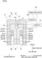
- the first heater 13 includes: a heat source 51; a heating unit 52; a sensor 57 configured to detect the temperature of the heating unit 52; a current giving circuit 58; a thermostat 70; heat insulating materials 59; a box 60; and a controller 100.
- the first heater 13 is configured to simultaneously heat the yarns Ya and Yb by causing the running yarns Ya and Yb to make contact with the heating unit 52 heated by the heat source 51.
- the heat source 51 is a heat source of a resistance-heating type, which is configured to generate heat when an electric current runs in a heating wire such as a Nichrome wire.
- Examples of the heat source of the resistance-heating type include a sheathed heater including a heating wire (such as a coil) and a pipe surrounding the heating wire.
- the heat source 51 extends along the extending direction.
- the heating length of the heat source 51 (the length of the heat source 51 along the extending direction) is, e.g., 1.0 m.
- the heat source 51 is connected to the current giving circuit 58.
- the current giving circuit 58 is provided for causing an electric current to run in the heating wire of the heat source 51.
- the heat source 51 is configured to generate Joule heat in such a way that the current giving circuit 58 supplies an electric current to the heating wire of the heat source 51
- the current giving circuit 58 is electrically connected to the controller 100.
- the controller 100 may be electrically connected to each device constituting the false-twist texturing machine 1, in addition to the current giving circuit 58 of the first heater 13.
- the controller 100 is programmed to turn on/off the current giving circuit 58 based on an output signal of the sensor 57 (PWM control), so as to switch a state in which an electric current is supplied to the heating wire of the heat source 51 and a state in which an electric current is not supplied to the heating wire of the heat source 51.
- the controller 100 when a value detected by the sensor 57 (hereinafter, this will be referred to as a detection value of the sensor 57) is sufficiently lower than a target temperature, the controller 100 maintains the state in which an electric current is supplied to the heating wire of the heat source 51.
- the controller 100 controls the following times so that the detection value of the sensor 57 does not exceed the target temperature: the time of the state in which an electric current is supplied to the heating wire of the heat source 51; and the time of the state in which an electric current is not supplied to the heating wire of the heat source 51.
- the controller 100 maintains the state in which an electric current is not supplied to the heating wire of the heat source 51.
- the controller 100 controls the following times so that the detection value of the sensor 57 does not become lower than the target temperature: the time of the state in which an electric current is not supplied to the heating wire of the heat source 51; and the time of the state in which an electric current is supplied to the heating wire of the heat source 51.
- This target temperature is suitably set in accordance with a driving condition such as the type, brand (thickness), and running speed of each yarn Y.
- the controller 100 is able to control the temperature of the heat source 51 (the heating temperature of the first heater 13).
- a control point (i.e., reference point) regarding the temperature control by the controller 100 is at a position (a central part of the heating unit 52 in the extending direction) where the sensor 57 is provided in the heating unit 52.
- the controller 100 is programmed to control an upper limit of heating temperature of the first heater 13. In other words, the controller 100 is programmed to perform control so that a detection value of the sensor 57 is kept to be equal to or less than 320 °C.
- a detection value of the sensor 57 is increased to a predetermined upper limit of temperature (i.e., upper limit temperature)
- the controller 100 performs the switching to the state in which an electric current is not supplied to the heating wire of the heat source 51, i.e., decreases the temperature of the heat source 51.
- the upper limit temperature is equal to or less than 320 °C. This upper limit temperature is a fixed value and does not vary depending on the driving condition such as the type, brand (thickness), and running speed of each yarn Y.
- the thermostat 70 is provided between the current giving circuit 58 and the heat source 51.
- the thermostat 70 is configured to physically shut off a circuit between the current giving circuit 58 and the heat source 51 when the temperature of one heating member 53 is a predetermined unusual temperature which is equal to or more than 400 °C and equal to or less than 450 °C. With this arrangement, an electric current which is supplied to the heat source 51 is shut off. That is, the thermostat 70 is equivalent to a " breaker (i.e., circuit breaker) " of the present invention.
- the heating unit 52 is heated by the heat generated by the heat source 51. As shown in FIG. 5 , the heating unit 52 extends in the extending direction along the heat source 51.
- the heating unit 52 includes, e.g., two heating members 53 (heating members 53a and 53b) and two yarn contacted portions 54 (yarn contacted portions 54a and 54b).
- the heating member 53a and the yarn contacted portion 54a are members for heating the yarn Ya.
- the heating member 53b and the yarn contacted portion 54b are members for heating the yarn Yb.
- the members for heating the yarn Ya and (ii) the members for heating the yarn Yb are provided to oppose each other over the heat source 51 in, e.g., the base longitudinal direction.
- the heating member 53a is made of aluminum or aluminum alloy.
- the heating member 53a extends in the extending direction along the heat source 51.
- the heating member 53a is in contact with the heat source 51.
- the heating member 53a is provided on one side of the heat source 51 in the base longitudinal direction (on the left side of the sheet of FIG. 4 ) .
- the heating member 53a includes, e.g., one slit 55 (slit 55a) extending in the extending direction.
- the slit 55a is reverse U-shaped in a cross section orthogonal to the extending direction.
- the slit 55a is open in a direction opposite to one side (upper side in the sheet of FIG.
- one yarn contacted portion 54 (yarn contacted portion 54a) is housed.
- the yarn contacted portion 54a forms a yarn path for the yarn Ya to run.
- the yarn contacted portion 54a is a long member made of, e.g., SUS.
- the yarn contacted portion 54a extends at least in the extending direction.
- the yarn contacted portion 54a is fixed to the heating member 53a while being in contact with the heating member 53a.
- the temperature of the yarn contacted portion 54a is increased by the heat transmitted from the heat source 51 via the heating member 53a.
- the yarn contacted portion 54a has one yarn contacted surface 56 (yarn contacted surface 56a) for allowing a corresponding yarn Y to make contact therewith.
- the yarn contacted surface 56a is oriented at least to the other side in the height direction. As shown in FIG.
- the yarn contacted surface 56a is substantially U-shaped and curved to protrude toward the other side in the height direction in a cross section orthogonal to the base longitudinal direction. As shown in FIG. 4 , for example, when viewed in the extending direction, the yarn contacted surface 56a is reverse U-shaped and curved to protrude toward one side in the height direction.
- the heating member 53b is provided on the other side of the heat source 51 in the base longitudinal direction (on the right side of the sheet of FIG. 4 ).
- the heating member 53b is in contact with the heat source 51.
- the heating member 53b includes a slit 55b which is identical in shape with the slit 55a.
- a yarn contacted portion 54b which is structured in the same manner as the yarn contacted portion 54a is housed.
- the yarn contacted portion 54b has a yarn contacted surface 56b which is identical in shape with the yarn contacted surface 56a. The details of these members will be omitted.
- the sensor 57 is provided at an end portion of the heating unit 52 on one side in the height direction.
- the sensor 57 is provided in a concave portion 52a formed across end faces of two heating members 53a and 53b on one side in the height direction as shown in FIG. 4 . This enables the sensor 57 to detect the temperature of each heating member 53 in the heating unit 52.
- the sensor 57 is provided on one side of the heat source 51 in the height direction.
- the sensor 57 is provided at the central part of the heating unit 52 in the extending direction so as to nearly overlap the heat source 51 in the height direction.
- the heating unit 52 is housed in the box 60.
- the box 60 is a hollow member which is rectangular parallelepiped in shape and which is long in the extending direction.
- An opening 61 is formed on a side wall of the box 60 on the other side in the height direction.
- the opening 61 allows the slits 55 of two heating members 53 to communicate with the outside of the box 60.
- openings 62 and 63 are respectively formed on both side walls of the box 60 in the extending direction. The openings 62 and 63 allow the slits 55 of two heating members 53 to communicate with the outside of the box 60.
- the heat insulating materials 59 are provided to fill gaps between the box 60 and the heating unit 52 housed in the box 60.
- the heat insulating materials 59 cover (i) both side walls of the heating unit 52 in the base longitudinal direction and (ii) both side walls of the heating unit 52 in the height direction. In this regard, both side walls of the heating unit 52 in the extending direction are not covered by the heat insulating materials 59 and are exposed to the outside air.
- the heat insulating materials 59 are not provided on the other side of the slits 55 in the height direction.
- spaces of the yarn contacted portions 54 housed in the respective slits 55 are open on the other side of (to be more specific, the lower side of) the yarn contacted surfaces 56 in the height direction as shown in FIG. 4 and FIG. 6 .
- the word "open” indicates that (i) there is no member below the yarn contacted surfaces 56 in the first heater 13 and (ii) there is a space which allows the yarns Y to drop off from the first heater 13 by their own weight at the time of yarn breakage.
- the running yarns Y make contact with the respective yarn contacted surfaces 56 so as to be heated by the heating unit 52 via the respective yarn contacted surfaces 56 (in a contact manner). In this way, the yarns Y are heated.
- the temperature of each yarn Y is increased to an appropriate processing temperature in such a way that the type, brand (thickness), and running speed of the yarn Y and the heating temperature of the first heater 13 are properly set.
- the heating temperature of the first heater 13 is not necessarily identical with the processing temperature.
- the heating temperature of the first heater 13 is typically set to be higher than a target value of the processing temperature.
- each first heater 13 will detail the arrangement of each first heater 13 with reference to FIG. 7 and FIG. 8 .
- each yarn contacted surface 56 is substantially U-shaped and curved in a cross section orthogonal to the base longitudinal direction (i.e., cross section parallel to both the up-down direction and the extending direction).
- a central part (in the vicinity of a point P0 shown in FIG. 7 ) of the yarn contacted surface 56 in the extending direction is substantially parallel to the extending direction.
- both end parts of the yarn contacted surface 56 in the extending direction are inclined from the extending direction.
- An end of the yarn contacted surface 56 on the one side in the extending direction (at a point P1 shown in FIG.
- an inclination angle between the yarn contacted surface 56 and the horizontal direction at the point P1 is defined as an angle ⁇ 1 in a cross section orthogonal to the base longitudinal direction.
- an inclination angle between the yarn contacted surface 56 and the horizontal direction at the point P2 is defined as an angle ⁇ 2. The following will describe the detailed definition of the angles ⁇ 1 and ⁇ 2.
- the angle ⁇ 1 is an angle formed in a cross section orthogonal to the base longitudinal direction between (i) a part of a tangent (tangent T1) at the point P1 of the yarn contacted surface 56 and (ii) a linear line L1 which is substantially horizontal along the base width direction. This part of the tangent T1 is provided on the one side in the extending direction.
- the angle ⁇ 1 is a positive angle.
- the angle ⁇ 1 is a negative angle.
- the angle ⁇ 2 is an angle formed in a cross section orthogonal to the base longitudinal direction between (i) a part of a tangent (tangent T2) at the point P2 of the yarn contacted surface 56 and (ii) a linear line L2 which is substantially horizontal along the base width direction. This part of the tangent T2 is provided on one side of the point P2 in the extending direction.
- the angle ⁇ 2 is a positive angle.
- the angle ⁇ 2 is a negative angle.
- each inclination angle of the yarn contacted surface 56 with respect to the horizontal direction between the points P1 and P2 is within a range between the angle ⁇ 1 and the angle ⁇ 2.
- the inclination angle of the yarn contacted surface 56 with respect to the horizontal direction is within a range of -60 degrees to 60 degrees.
- each inclination angle of the entire yarn contacted surface 56 between the points P1 and P2 with respect to the horizontal direction is within a range of -60 to 60 degrees.
- each inclination angle of the entire yarn contacted surface 56 with respect to the horizontal direction is within a range of -60 degrees to 60 degrees.
- the yarn contacted surface 56 in the first heater 13 there is a non-closed space below (immediately below) the yarn contacted surface 56 in the first heater 13, and the inclination angle of the yarn contacted surface 56 with respect to the horizontal direction is within a predetermined range in a cross section orthogonal to the base longitudinal direction.
- FIG. 9 is a graph of temperature distribution of a yarn contacted surface in the extending direction of each of the heating members of Example and Comparative Example when set temperature is arranged to be 100, 200, and 300 °C (i.e., when a detection value of a sensor in regard to the temperature of a heating unit (the temperature at the control point) is controlled to be 100, 200, and 300 °C).
- the heat capacity of the heating member is 2904 J/K.
- the graph of FIG. 9 shows that, at any set temperature, the degree of decrease in temperature at both end portions of the yarn contacted surface of the heating member made of aluminum (Example) in the extending direction is smaller than that at both end portions of the yarn contacted surface of the heating member made of brass (Comparative Example).
- the yarn contacted surface of Example has the small degree of decrease in temperature at a part distant from the control point. This is because, as described later, the heat conductivity of aluminum is higher than that of brass.
- FIG. 10 is a graph of power consumption in each of the heating members of Example and Comparative Example when the set temperature is arranged to be 100, 200, and 300 °C in a loadless state (a state in which a yarn Y is not heated) .
- the heating member made of aluminum in Example and the heating member made of brass in Comparative Example are scarcely different in regard to power consumption.
- the table of FIG. 11 shows physical properties of the melting point, specific heat, specific weight, and heat conductivity of each of (i) aluminum which was used as the material of the heating member of Example in the above-described comparison test and (ii) brass which was used as the material of the heating member of Comparative Example in the above-described comparison test.
- the table of FIG. 11 shows the physical properties of aluminum at 20 °C.
- the table of FIG. 11 shows the physical properties of cartridge brass (i.e., brass containing about 70 % Cu and 30 % Zn) whose zinc content is 30 percent.
- the melting point of aluminum is 660 °C and is lower than that of brass (1205 °C).
- the specific heat of aluminum is 900 J/kg°C, and is higher than that of brass (385 J/kg°C) .
- the specific weight of aluminum is 2.7 g/cm 3 , and lower than that of brass (8.56 g/cm 3 ).
- the heat conductivity of aluminum is 204 W/mk, and is higher than that of brass (99 W/mk) .
- the false-twist texturing machine 1 of the present embodiment includes each first heater 13 which is configured to heat running yarns Y made of synthetic fibers and which includes the heat source 51, the heating unit 52 heated by the heat source 51, and the controller 100 programmed to control the temperature of the heat source 51.
- the heating unit 52 includes: the yarn contacted portions 54 having the respective yarn contacted surfaces 56 with which the running yarns Y make contact; and the heating members 53 provided for heating the yarn contacted portions 54 by means of the heat generated in the heat source 51.
- Each heating member 53 is made of metal including aluminum, and the controller 100 is programmed to control the temperature of the heat source 51 so that the temperature of the heating member 53 is kept to be equal to or less than 320 °C.
- the first heater 13 is configured to heat the yarns Y in a contact manner such that the yarns Y in contact with the yarn contacted surfaces 56 are heated.
- the heating temperature in this arrangement is lower than the heating temperature when the yarns Y are heated in a contactless manner. That is, the yarns Y are properly heated even when the temperature of the heating members 53 is equal to or less than 320 °C.
- aluminum whose melting point is relatively low, as the material of each heating member 53.
- aluminum is relatively high in specific heat and relatively low in specific weight. With aluminum, a certain degree of heat capacity is achieved with a relatively small mass as compared to brass. Cost reduction is therefore achieved. Because aluminum is higher in heat conductivity than brass, high temperature of the heating member 53 is maintained in the yarn running direction.
- each yarn contacted portion 54 extends at least in the extending direction intersecting with a vertical direction
- the first heater 13 is arranged so that (i) the yarn contacted surface 56 is oriented at least to the lower side and (ii) each inclination angle of the yarn contacted surface 56 with respect to the horizontal direction is within a range of -60 degrees to 60 degrees in a cross section parallel to both the vertical direction and the extending direction.
- the yarn Y is allowed to quickly leave the yarn contacted surface 56 by its own weight at the time of yarn breakage. It is therefore possible to avoid the yarn Y from melting in the first heater 13 and being adhered to the first heater 13 at the time of yarn breakage.
- the heat source 51 is configured to generate heat by being supplied with an electric current.
- the false-twist texturing machine 1 includes: the sensor 57 configured to detect the temperature of each heating member 53; and the current giving circuit 58 which is able to supply an electric current to the heating wire of the heat source 51.
- the controller 100 is programmed to turn on/off the current giving circuit 58 based on a detection value of the sensor 57, so as to switch the state in which an electric current is supplied to the heat source 51 and the state in which an electric current is not supplied to the heat source 51.
- the false-twist texturing machine 1 of the present embodiment further includes the thermostat 70 configured to shut off an electric current supplied to the heat source 51 when the temperature of one heating member 53 is a predetermined unusual temperature which is equal to or more than 400 °C and equal to or less than 450 °C.
- the controller 100 cannot control the temperature of each heating member 53 because of the malfunction of the sensor 57, etc., the temperature of the heating member 53 may be increased to be higher than the upper limit temperature.
- the heating member 53 of the present embodiment is made of metal including aluminum. In this regard, the melting point of pure aluminum whose purity is equal to or more than 99 % is 660 °C.
- the melting point of Al-Cu alloy is within a range of 500 to 640 °C.
- the melting point of Al-Mn alloy is 640 °C.
- the melting point of Al-Si alloy is within a range of 530 to 570 °C.
- the melting point of Al-Mg alloy is within a range of 570 to 650 °C.
- the melting point of Al-Mg-Si alloy is within a range of 580 to 650 °C.
- the melting point of Al-Zn-Mg alloy is within a range of 480 to 640 °C.
- the thermostat 70 shuts off an electric current supplied to the heat source 51.
- the increase in temperature of the heating member 53 made of metal including aluminum is suppressed.
- the heating member 53 is prevented from melting or almost melting. It is therefore possible to avoid the decrease in strength of the heating member 53.
- the thermostat 70 shuts off an electric current supplied to the heat source 51.
- the disclosure is not limited to this.
- a thermal fuse may be used instead of the thermostat 70.
- a breaker such as the thermostat 70 and the thermal fuse may not be provided.
- the sensor 57 is provided in the concave portion 52a formed across the end faces of two heating members 53a and 53b on one side in the height direction and nearly overlaps the heat source 51 in the height direction.
- the sensor 57 may be provided in a different manner.
- the sensor 57 may be provided so that the sensor 57 and the heat source 51 are aligned in the base longitudinal direction.
- the sensor 57 is preferably provided in the vicinity of the heat source 51.
- the first heater 13 is arranged so that (i) the yarn contacted surface 56 is oriented at least to the lower side and (ii) each inclination angle of the yarn contacted surface 56 with respect to the horizontal direction is within a range of -60 degrees to 60 degrees in a cross section parallel to the vertical direction and the extending direction.
- the yarn contacted surface 56 may be oriented to its upper side.
- Each inclination angle of the yarn contacted surface 56 with respect to the horizontal direction may not be within a range of -60 degrees to 60 degrees.
- the present invention is applied to the false-twist texturing machine 1 configured to false-twist the yarns Y.
- the disclosure is not limited to this.
- the present invention is applicable to a yarn processor configured to perform, for yarns formed of synthetic fibers, various processes such as yarn combining in addition to false twisting.
Landscapes
- Engineering & Computer Science (AREA)
- Textile Engineering (AREA)
- Mechanical Engineering (AREA)
- Yarns And Mechanical Finishing Of Yarns Or Ropes (AREA)
Abstract
Description
- The present invention relates to a yarn processor including a heater configured to heat a yarn.
- A known heater is configured to heat a yarn formed of synthetic fibers in a yarn processor configured to perform various processes for the yarn such as yarn combining and false twisting. For example, Patent Literature 1 (
Japanese Laid-Open Patent Publication No. 2002-220755 - In such a heater, brass whose heat resisting temperature is relatively high is typically used as the material of the heating member. In this regard, the heating member preferably has a relatively high heat capacity in order to suppress the variation of temperature of the heating member due to disturbance factors. However, the specific heat of brass is relatively low. Therefore, when the heating member made of brass is arranged to have a relatively high heat capacity, the mass of the heating member is large. This results in cost increase.
- In the heating member of such a heater, the temperature at a predetermined position (control point, i.e., reference point) in a yarn running direction is controlled to be a predetermined temperature. In this regard, the heat conductivity of brass is relatively low. As compared to a heating member made of another material, the heating member made of brass has the large degree of decrease in temperature at a part distant from the control point in the yarn running direction.
- An object of the present invention is to provide a yarn processor capable of achieving cost reduction and of maintaining high temperature of a heating member in the yarn running direction.
- According to a first aspect of the invention, a yarn processor includes a heater configured to heat a running yarn made of synthetic fibers. This heater includes a heat source, a heating unit heated by the heat source, and a controller programmed to control the temperature of the heat source. The above-described heating unit includes: a yarn contacted portion having a yarn contacted surface with which the running yarn makes contact; and a heating member configured to receive heat generated by the heat source and to heat the yarn contacted portion. This heating member is made of metal including aluminum. The above-described controller is programmed to control the temperature of the heat source so that the temperature of the heating member is kept to be equal to or less than 320 °C.
- A contact manner in which the yarn is heated while being in contact with the yarn contacted surface is applied to the present invention. Therefore, the set temperature of the heat source is low in the contact manner as compared to in a contactless manner. That is, the yarn is properly heated even when the temperature of the heating member is equal to or less than 320 °C. It is therefore possible to use aluminum whose melting point is relatively low, as the material of the heating member. In this regard, aluminum is relatively high in specific heat and relatively low in specific weight. Therefore, a relatively high heat capacity is achieved with a small mass of aluminum as compared to a case of brass. Cost reduction is therefore achieved. Because aluminum is higher in heat conductivity than brass, high temperature of the heating member is maintained in a yarn running direction.
- The heat source is a heat source of a resistance-heating type, which is configured to generate heat when an electric current runs in a heating wire such as a Nichrome wire. Examples of the heat source of the resistance-heating type include a sheathed heater.
- According to a second aspect of the invention, the yarn processor is arranged such that the yarn contacted portion extends at least in an extending direction intersecting with a vertical direction, and the heater is arranged so that the yarn contacted surface is oriented at least to a lower side of the yarn contacted surface and an inclination angle of the yarn contacted surface with respect to a horizontal direction is within a range of -60 degrees to 60 degrees in a cross section parallel to the vertical direction and the extending direction.
- According to this aspect, the yarn is allowed to quickly leave the yarn contacted surface by its own weight at the time of yarn breakage. It is therefore possible to avoid the yarn melting in the heater and being adhered to the heater at the time of yarn breakage.
- According to a third aspect of the invention, the yarn processor further includes a sensor configured to detect the temperature of the heating member; and a current giving circuit which is able to supply an electric current to the heat source configured to generate the heat by receiving an electric current. In this regard, the controller is programmed to control the current giving circuit based on a detection value of the sensor so as to switch between a state in which an electric current is supplied to the heat source and a state in which an electric current is not supplied to the heat source.
- According to this aspect, cost reduction is achieved with a simple control as compared to a case where the magnitude of an electric current and voltage which are supplied to the heat source is controlled.
- According to a fourth aspect of the invention, the yarn processor further includes a breaker configured to shut off an electric current supplied to the heat source when the temperature of the heating member is a predetermined temperature which is equal to or more than 400 °C and equal to or less than 450 °C.
- According to this aspect, when (i) the controller cannot control the temperature of the heating member because of malfunction of the sensor, etc. and (ii) the temperature of the heating member is the predetermined temperature which is equal to or more than 400 °C and equal to or less than 450 °C, the breaker shuts off an electric current supplied to the heat source. It is therefore possible to suppress the increase in temperature of the heating member and to avoid the decrease in strength of the heating member.
-
-
FIG. 1 is a profile of a false-twist texturing machine of an embodiment of the present invention. -
FIG. 2 is a schematic diagram of the false-twist texturing machine, expanded along paths of yarns. -
FIG. 3 shows a first heater. -
FIG. 4 is a cross section taken along a line IV-IV inFIG. 3 . -
FIG. 5 is a cross section taken along a line V-V inFIG. 4 . -
FIG. 6 is a cross section taken along a line VI-VI inFIG. 4 . -
FIG. 7 illustrates how an inclination angle of a yarn contacted surface with respect to a horizontal direction is defined. - Each of
FIGs. 8(a) and 8(b) illustrates the limit of the inclination angle of the yarn contacted surface with respect to the horizontal direction. -
FIG. 9 is a graph of temperature distribution of the yarn contacted surface of each of heating members of Example and Comparative Example. -
FIG. 10 is a graph of power consumption in each of the heating members of Example and Comparative Example. -
FIG. 11 is a table of physical properties of aluminum and brass. - The following will describe a false-
twist texturing machine 1 of a preferred embodiment of the present invention, with reference toFIG. 1 . Hereinafter, vertical direction to the sheet ofFIG. 1 is defined as a base longitudinal direction, and a left-right direction to the sheet is defined as a base width direction. A direction orthogonal to the base longitudinal direction and the base width direction is defined as an up-down direction (vertical direction) in which the gravity acts. In this regard, the base longitudinal direction and the base width direction are substantially in parallel to a horizontal direction. - The false-
twist texturing machine 1 is able to perform false twisting of yarns Y (i.e., to false-twist the yarns Y) made of synthetic fibers such as nylon (polyamide fibers) and polyester. The false-twist texturing machine 1 includes ayarn supplying unit 2 for supplying the yarns Y, aprocessing unit 3 configured to false-twist the yarns Y supplied from theyarn supplying unit 2, and awinding unit 4 configured to wind the yarns Y processed by theprocessing unit 3 onto winding bobbins Bw. Components of theyarn supplying unit 2, theprocessing unit 3, and thewinding unit 4 are aligned to form plural lines (seeFIG. 2 ) in the base longitudinal direction. The base longitudinal direction is a direction orthogonal to a running plane (plane ofFIG. 1 ) of the yarns Y. The running plane of the yarns Y is formed of the yarn paths extending from theyarn supplying unit 2 to thewinding unit 4 through theprocessing unit 3. - The
yarn supplying unit 2 includes acreel stand 5 retaining yarn supply packages Ps. Theyarn supplying unit 2 is configured to supply the yarns Y to theprocessing unit 3. Theprocessing unit 3 is configured to false-twist the yarns Y supplied from the yarn supply packages Ps. In theprocessing unit 3, the following members are placed in this order from the upstream side in a yarn running direction: eachfirst feed roller 11; each twist-stoppingguide 12; each first heater 13 (equivalent to a heater of the present invention); each cooler 14; each false-twistingdevice 15; eachsecond feed roller 16; each interlacingdevice 17; eachthird feed roller 18; asecond heater 19; and eachfourth feed roller 20. The windingunit 4 includes windingdevices 21. Each windingdevice 21 is configured to wind a yarn Y false-twisted by theprocessing unit 3 onto a winding bobbin Bw, so as to form a wound package Pw. - The false-
twist texturing machine 1 includes amain base 8 and a windingbase 9 which are spaced apart from each other in the base width direction. Themain base 8 and the windingbase 9 are substantially identical in length in the base longitudinal direction. Themain base 8 and the windingbase 9 oppose each other in the base width direction. An upper part of themain base 8 is connected to an upper part of the windingbase 9 by a supportingframe 10. Each device forming theprocessing unit 3 is mainly attached to themain base 8 or the supportingframe 10. Each device forming the windingunit 4 is mainly attached to the windingbase 9. Themain base 8, the windingbase 9, and the supportingframe 10 form a working space A in which an operator performs an operation such as yarn threading to each device. The yarn paths are formed so that the yarns Y mainly run around the working space A. - The false-
twist texturing machine 1 further includes units termed spans each of which includes a pair of themain base 8 and the windingbase 9 provided to oppose each other. In one span, processing units (which are also termed spindles) in which yarn paths are formed to pass the devices constituting theprocessing unit 3 are aligned in the base longitudinal direction. With this arrangement, in one span, the yarns Y running while being aligned in the base longitudinal direction can be simultaneously false-twisted. In the false-twist texturing machine 1, the spans are placed in a left-right symmetrical manner to the sheet, with a center line C in the base width direction of themain frame 8 being set as a symmetry axis. Themain frame 8 is shared between the left span and the right span. - The following will describe the structure of the
processing unit 3 with reference toFIG. 1 andFIG. 2 . Eachfirst feed roller 11 is configured to unwind a yarn Y from one yarn supply package Ps attached to theyarn supplying unit 2 and to send the yarn Y to onefirst heater 13. As shown inFIG. 2 , eachfirst feed roller 11 is configured to send, e.g., a single yarn Y to thefirst heater 13. Alternatively, eachfirst feed roller 11 may be able to send plural adjacent yarns Y to the downstream side in the yarn running direction. Each twist-stoppingguide 12 prevents twisting, which is applied to a yarn Y by one false-twistingdevice 15, from being propagated to the upstream side of each twist-stoppingguide 12 in the yarn running direction. - Each
first heater 13 is configured to heat yarns Y which are sent from somefirst feed rollers 11, to a predetermined processing temperature. As shown inFIG. 2 , eachfirst heater 13 is able to heat, e.g., two yarns Y. Eachfirst heater 13 will be detailed later. - Each cooler 14 is configured to cool a yarn Y heated by one
first heater 13. As shown inFIG. 2 , each cooler 14 is configured to cool, e.g., a single yarn Y. Alternatively, the cooler 14 may be able to simultaneously cool plural yarns Y. Each false-twistingdevice 15 is provided downstream of one cooler 14 in the yarn running direction, and configured to twist a yarn Y. Each false-twistingdevice 15 is, e.g., a so-called disc-friction false-twisting device. However, the disclosure is not limited to this. Eachsecond feed roller 16 is configured to send a yarn Y processed by one false-twistingdevice 15 to oneinterlacing device 17. The conveyance speed of conveying the yarn Y by eachsecond feed roller 16 is higher than the conveyance speed of conveying the yarn Y by eachfirst feed roller 11. The yarn Y is therefore drawn and false-twisted between thefirst feed roller 11 and thesecond feed roller 16. - Each interlacing
device 17 is configured to interlace a yarn Y. Each interlacingdevice 17 has, e.g., a known interlace nozzle configured to interlace the yarn Y by means of an airflow. - Each
third feed roller 18 is configured to send, to thesecond heater 19, a yarn Y running on the downstream side of one interlacingdevice 17 in the yarn running direction. As shown inFIG. 2 , eachthird feed roller 18 is configured to send, e.g., a single yarn Y to thesecond heater 19. Alternatively, eachthird feed roller 18 may be able to send plural adjacent yarns Y to the downstream side in the yarn running direction. The conveyance speed of conveying the yarn Y by eachthird feed roller 18 is lower than the conveyance speed of conveying the yarn Y by eachsecond feed roller 16. The yarn Y is therefore relaxed between thesecond feed roller 16 and thethird feed roller 18. - The
second heater 19 is configured to heat yarns Y sent from somethird feed rollers 18. Thesecond heater 19 extends along the vertical direction, and is provided for each of the spans. Eachfourth feed roller 20 is configured to send a yarn Y heated by thesecond heater 19 to one windingdevice 21. As shown inFIG. 2 , eachfourth feed roller 20 is able to send, e.g., a single yarn Y to the windingdevice 21. Alternatively, eachfourth feed roller 20 may be able to send plural adjacent yarns Y to the downstream side in the yarn running direction. The conveyance speed of conveying the yarn Y by eachfourth feed roller 20 is lower than the conveyance speed of conveying the yarn Y by eachthird feed roller 18. The yarn Y is therefore relaxed between thethird feed roller 18 and thefourth feed roller 20. - In the
processing unit 3 arranged as described above, each yarn Y drawn between thefirst feed roller 11 and thesecond feed roller 16 is twisted by the false-twistingdevice 15. The twist formed by the false-twistingdevice 15 propagates to the twist-stoppingguide 12, but does not propagate to the upstream side of the twist-stoppingguide 12 in the yarn running direction. The yarn Y which is twisted and drawn is heated by thefirst heater 13 and thermally set. After that, the yarn Y is cooled by the cooler 14. The yarn Y is untwisted on the downstream side of the false-twistingdevice 15 in the yarn running direction. However, the yarn Y is maintained to be wavy in shape on account of the thermal setting described above (i.e., crimp contraction of the yarn Y is maintained). - After being false-twisted, the yarn Y is interlaced by the interlacing
device 17 while being relaxed between thesecond feed roller 16 and thethird feed roller 18. The yarn Y is then guided to the downstream side in the yarn running direction. Furthermore, the yarn Y is thermally processed by thesecond heater 19 while being relaxed between thethird feed roller 18 and thefourth feed roller 20. Finally, the yarn Y sent from thefourth feed roller 20 is wound by the windingdevice 21. - The following will describe the structure of the winding
unit 4 with reference toFIG. 2 . The windingunit 4 includes plural windingdevices 21. Each windingdevice 21 is able to wind one yarn Y onto one winding bobbin Bw. The windingdevice 21 includes afulcrum guide 41, atraverse unit 42, and acradle 43. Thefulcrum guide 41 is a guide functioning as a fulcrum when the yarn Y is traversed. Thetraverse unit 42 is able to traverse the yarn Y by means of atraverse guide 45. Thecradle 43 is configured to rotatably support the winding bobbin Bw. Acontact roller 46 is provided in the vicinity of thecradle 43. Thecontact roller 46 is configured to apply a contact pressure to a surface of one wound package Pw by making contact with the surface of the wound package Pw. In the windingunit 4 arranged as described above, the yarn Y sent from thefourth feed roller 20 described above is wound onto the winding bobbin Bw by each windingdevice 21 so as to form the wound package Pw. - The following will detail each
first heater 13 with reference toFIG. 3 to FIG. 6 . As shown inFIG. 3 , thefirst heater 13 extends in a predetermined extending direction orthogonal to the base longitudinal direction. The extending direction is a direction intersecting with the up-down direction (vertical direction). Hereinafter, a direction orthogonal to the base longitudinal direction and the extending direction is defined as a height direction. - The
first heater 13 is configured to heat at least one running yarn Y. In the present embodiment, thefirst heater 13 is able to heat, e.g., two yarns Y (yarns Ya and Yb: seeFIG. 4 ). - As shown in
FIG. 4 andFIG. 5 , thefirst heater 13 includes: aheat source 51; aheating unit 52; asensor 57 configured to detect the temperature of theheating unit 52; acurrent giving circuit 58; athermostat 70;heat insulating materials 59; abox 60; and acontroller 100. Thefirst heater 13 is configured to simultaneously heat the yarns Ya and Yb by causing the running yarns Ya and Yb to make contact with theheating unit 52 heated by theheat source 51. - The
heat source 51 is a heat source of a resistance-heating type, which is configured to generate heat when an electric current runs in a heating wire such as a Nichrome wire. Examples of the heat source of the resistance-heating type include a sheathed heater including a heating wire (such as a coil) and a pipe surrounding the heating wire. Theheat source 51 extends along the extending direction. The heating length of the heat source 51 (the length of theheat source 51 along the extending direction) is, e.g., 1.0 m. Theheat source 51 is connected to the current givingcircuit 58. Thecurrent giving circuit 58 is provided for causing an electric current to run in the heating wire of theheat source 51. Theheat source 51 is configured to generate Joule heat in such a way that the current givingcircuit 58 supplies an electric current to the heating wire of theheat source 51 - The
current giving circuit 58 is electrically connected to thecontroller 100. Thecontroller 100 may be electrically connected to each device constituting the false-twist texturing machine 1, in addition to the current givingcircuit 58 of thefirst heater 13. Thecontroller 100 is programmed to turn on/off the current givingcircuit 58 based on an output signal of the sensor 57 (PWM control), so as to switch a state in which an electric current is supplied to the heating wire of theheat source 51 and a state in which an electric current is not supplied to the heating wire of theheat source 51. For a specific example, when a value detected by the sensor 57 (hereinafter, this will be referred to as a detection value of the sensor 57) is sufficiently lower than a target temperature, thecontroller 100 maintains the state in which an electric current is supplied to the heating wire of theheat source 51. When the detection value of thesensor 57 approaches the target temperature, thecontroller 100 controls the following times so that the detection value of thesensor 57 does not exceed the target temperature: the time of the state in which an electric current is supplied to the heating wire of theheat source 51; and the time of the state in which an electric current is not supplied to the heating wire of theheat source 51. Meanwhile, when the detection value of thesensor 57 is sufficiently higher than the target temperature, thecontroller 100 maintains the state in which an electric current is not supplied to the heating wire of theheat source 51. When the detection value of thesensor 57 approaches the target temperature, thecontroller 100 controls the following times so that the detection value of thesensor 57 does not become lower than the target temperature: the time of the state in which an electric current is not supplied to the heating wire of theheat source 51; and the time of the state in which an electric current is supplied to the heating wire of theheat source 51. This target temperature is suitably set in accordance with a driving condition such as the type, brand (thickness), and running speed of each yarn Y. - As described above, the
controller 100 is able to control the temperature of the heat source 51 (the heating temperature of the first heater 13). A control point (i.e., reference point) regarding the temperature control by thecontroller 100 is at a position (a central part of theheating unit 52 in the extending direction) where thesensor 57 is provided in theheating unit 52. - The
controller 100 is programmed to control an upper limit of heating temperature of thefirst heater 13. In other words, thecontroller 100 is programmed to perform control so that a detection value of thesensor 57 is kept to be equal to or less than 320 °C. For a specific example, when a detection value of thesensor 57 is increased to a predetermined upper limit of temperature (i.e., upper limit temperature), thecontroller 100 performs the switching to the state in which an electric current is not supplied to the heating wire of theheat source 51, i.e., decreases the temperature of theheat source 51. The upper limit temperature is equal to or less than 320 °C. This upper limit temperature is a fixed value and does not vary depending on the driving condition such as the type, brand (thickness), and running speed of each yarn Y. - The
thermostat 70 is provided between the current givingcircuit 58 and theheat source 51. Thethermostat 70 is configured to physically shut off a circuit between the current givingcircuit 58 and theheat source 51 when the temperature of oneheating member 53 is a predetermined unusual temperature which is equal to or more than 400 °C and equal to or less than 450 °C. With this arrangement, an electric current which is supplied to theheat source 51 is shut off. That is, thethermostat 70 is equivalent to a "breaker (i.e., circuit breaker)" of the present invention. - The
heating unit 52 is heated by the heat generated by theheat source 51. As shown inFIG. 5 , theheating unit 52 extends in the extending direction along theheat source 51. Theheating unit 52 includes, e.g., two heating members 53 (heating members portions heating member 53a and the yarn contactedportion 54a are members for heating the yarn Ya. Theheating member 53b and the yarn contactedportion 54b are members for heating the yarn Yb. (i) The members for heating the yarn Ya and (ii) the members for heating the yarn Yb are provided to oppose each other over theheat source 51 in, e.g., the base longitudinal direction. - The following will describe the members for heating the yarn Ya. The
heating member 53a is made of aluminum or aluminum alloy. Theheating member 53a extends in the extending direction along theheat source 51. Theheating member 53a is in contact with theheat source 51. For example, theheating member 53a is provided on one side of theheat source 51 in the base longitudinal direction (on the left side of the sheet ofFIG. 4 ) . Theheating member 53a includes, e.g., one slit 55 (slit 55a) extending in the extending direction. Theslit 55a is reverse U-shaped in a cross section orthogonal to the extending direction. Theslit 55a is open in a direction opposite to one side (upper side in the sheet ofFIG. 4 ) in the height direction, i.e., open on the other side (lower side in the sheet ofFIG. 4 ) in the height direction. In theslit 55a, one yarn contacted portion 54 (yarn contactedportion 54a) is housed. - The yarn contacted
portion 54a forms a yarn path for the yarn Ya to run. The yarn contactedportion 54a is a long member made of, e.g., SUS. The yarn contactedportion 54a extends at least in the extending direction. The yarn contactedportion 54a is fixed to theheating member 53a while being in contact with theheating member 53a. The temperature of the yarn contactedportion 54a is increased by the heat transmitted from theheat source 51 via theheating member 53a. The yarn contactedportion 54a has one yarn contacted surface 56 (yarn contactedsurface 56a) for allowing a corresponding yarn Y to make contact therewith. The yarn contactedsurface 56a is oriented at least to the other side in the height direction. As shown inFIG. 6 , for example, the yarn contactedsurface 56a is substantially U-shaped and curved to protrude toward the other side in the height direction in a cross section orthogonal to the base longitudinal direction. As shown inFIG. 4 , for example, when viewed in the extending direction, the yarn contactedsurface 56a is reverse U-shaped and curved to protrude toward one side in the height direction. - The following will describe the members for heating the yarn Yb. For example, the
heating member 53b is provided on the other side of theheat source 51 in the base longitudinal direction (on the right side of the sheet ofFIG. 4 ). Theheating member 53b is in contact with theheat source 51. Theheating member 53b includes aslit 55b which is identical in shape with theslit 55a. In theslit 55b, a yarn contactedportion 54b which is structured in the same manner as the yarn contactedportion 54a is housed. The yarn contactedportion 54b has a yarn contactedsurface 56b which is identical in shape with the yarn contactedsurface 56a. The details of these members will be omitted. - As shown in
FIG. 4 andFIG. 5 , thesensor 57 is provided at an end portion of theheating unit 52 on one side in the height direction. To be more specific, thesensor 57 is provided in aconcave portion 52a formed across end faces of twoheating members FIG. 4 . This enables thesensor 57 to detect the temperature of eachheating member 53 in theheating unit 52. Thesensor 57 is provided on one side of theheat source 51 in the height direction. As shown inFIG. 5 , thesensor 57 is provided at the central part of theheating unit 52 in the extending direction so as to nearly overlap theheat source 51 in the height direction.
theheating unit 52 is housed in thebox 60. Thebox 60 is a hollow member which is rectangular parallelepiped in shape and which is long in the extending direction. Anopening 61 is formed on a side wall of thebox 60 on the other side in the height direction. Theopening 61 allows theslits 55 of twoheating members 53 to communicate with the outside of thebox 60. In this regard,openings box 60 in the extending direction. Theopenings slits 55 of twoheating members 53 to communicate with the outside of thebox 60. - The
heat insulating materials 59 are provided to fill gaps between thebox 60 and theheating unit 52 housed in thebox 60. Theheat insulating materials 59 cover (i) both side walls of theheating unit 52 in the base longitudinal direction and (ii) both side walls of theheating unit 52 in the height direction. In this regard, both side walls of theheating unit 52 in the extending direction are not covered by theheat insulating materials 59 and are exposed to the outside air. Theheat insulating materials 59 are not provided on the other side of theslits 55 in the height direction. - With this arrangement, spaces of the yarn contacted
portions 54 housed in therespective slits 55 are open on the other side of (to be more specific, the lower side of) the yarn contactedsurfaces 56 in the height direction as shown inFIG. 4 andFIG. 6 . In this regard, the word "open" indicates that (i) there is no member below the yarn contactedsurfaces 56 in thefirst heater 13 and (ii) there is a space which allows the yarns Y to drop off from thefirst heater 13 by their own weight at the time of yarn breakage. - When each yarn Y properly runs, (i) the positional relationship between the
first heater 13 and the twist-stoppingguide 12 and (ii) the positional relationship between thefirst heater 13 and the cooler 14 are appropriately arranged so that the yarn Y reliably makes contact with a corresponding yarn contactedsurface 56. That is, at least a force toward the yarn contactedsurface 56 in the height direction is applied to the yarn Y running along the yarn contactedsurface 56. This prevents the yarn Y from moving away from the yarn contactedsurface 56. - In the
first heater 13 arranged as described above, the running yarns Y make contact with the respective yarn contactedsurfaces 56 so as to be heated by theheating unit 52 via the respective yarn contacted surfaces 56 (in a contact manner). In this way, the yarns Y are heated. The temperature of each yarn Y is increased to an appropriate processing temperature in such a way that the type, brand (thickness), and running speed of the yarn Y and the heating temperature of thefirst heater 13 are properly set. The heating temperature of thefirst heater 13 is not necessarily identical with the processing temperature. The heating temperature of thefirst heater 13 is typically set to be higher than a target value of the processing temperature. - The following will detail the arrangement of each
first heater 13 with reference toFIG. 7 andFIG. 8 . - As described above, each yarn contacted
surface 56 is substantially U-shaped and curved in a cross section orthogonal to the base longitudinal direction (i.e., cross section parallel to both the up-down direction and the extending direction). To be more specific, a central part (in the vicinity of a point P0 shown inFIG. 7 ) of the yarn contactedsurface 56 in the extending direction is substantially parallel to the extending direction. Except the central part of the yarn contactedsurface 56 in the extending direction, both end parts of the yarn contactedsurface 56 in the extending direction are inclined from the extending direction. An end of the yarn contactedsurface 56 on the one side in the extending direction (at a point P1 shown inFIG. 7 ) and an end of the yarn contactedsurface 56 on the other side in the extending direction (at a point P2 shown inFIG. 7 ) are most inclined from the extending direction as compared to the other part of thecontact surface 56. As shown inFIG. 7 , for example, when thefirst heater 13 is provided so that its extending direction is substantially in parallel to a horizontal direction, a part of the yarn contactedsurface 56 in the vicinity of the point P0 is also substantially in parallel to the horizontal direction in a cross section orthogonal to the base longitudinal direction. In this case, the end of the yarn contactedsurface 56 at the point P1 and the end of the yarn contactedsurface 56 at the point P2 are considerably inclined from the horizontal direction. - As shown in
FIG. 7 , an inclination angle between the yarn contactedsurface 56 and the horizontal direction at the point P1 is defined as an angle Θ1 in a cross section orthogonal to the base longitudinal direction. In this cross section, an inclination angle between the yarn contactedsurface 56 and the horizontal direction at the point P2 is defined as an angle Θ2. The following will describe the detailed definition of the angles Θ1 and Θ2. - The angle Θ1 is an angle formed in a cross section orthogonal to the base longitudinal direction between (i) a part of a tangent (tangent T1) at the point P1 of the yarn contacted
surface 56 and (ii) a linear line L1 which is substantially horizontal along the base width direction. This part of the tangent T1 is provided on the one side in the extending direction. When the tangent T1 is above the linear line L1 (seeFIG. 7 andFIG. 8(a) ), the angle Θ1 is a positive angle. When the tangent T1 is below the linear line L1 (seeFIG. 8(b) ), the angle Θ1 is a negative angle. - The angle Θ2 is an angle formed in a cross section orthogonal to the base longitudinal direction between (i) a part of a tangent (tangent T2) at the point P2 of the yarn contacted
surface 56 and (ii) a linear line L2 which is substantially horizontal along the base width direction. This part of the tangent T2 is provided on one side of the point P2 in the extending direction. When the tangent T2 is above the linear line L2 (FIG. 8(a) ), the angle Θ2 is a positive angle. When the tangent T2 is below the linear line L2 (seeFIG. 7 andFIG. 8(b) ), the angle Θ2 is a negative angle. In the cross section orthogonal to the base longitudinal direction, each inclination angle of the yarn contactedsurface 56 with respect to the horizontal direction between the points P1 and P2 is within a range between the angle Θ1 and the angle Θ2. - In the present embodiment, the inclination angle of the yarn contacted
surface 56 with respect to the horizontal direction is within a range of -60 degrees to 60 degrees. To be more specific, each inclination angle of the entire yarn contactedsurface 56 between the points P1 and P2 with respect to the horizontal direction (i.e., of the entire yarn contactedsurface 56 in the extending direction) is within a range of -60 to 60 degrees. In the present embodiment, when each of the angles Θ1 and Θ2 is within a range of -60 degrees to 60 degrees, each inclination angle of the entire yarn contactedsurface 56 with respect to the horizontal direction is within a range of -60 degrees to 60 degrees. - As described above, there is a non-closed space below (immediately below) the yarn contacted
surface 56 in thefirst heater 13, and the inclination angle of the yarn contactedsurface 56 with respect to the horizontal direction is within a predetermined range in a cross section orthogonal to the base longitudinal direction. With this arrangement, when the yarn breakage occurs while the false-twist texturing machine 1 is operated, the yarn Y is able to quickly leave the yarn contactedsurface 56 by its own weight and to drop off from thefirst heater 13. It is therefore possible to avoid the fusion of the yarn Y to thefirst heater 13 in the yarn breakage. - The present inventor performed a comparison test between (i) a case where the material of a heating member was aluminum (Example) as in the present embodiment and (ii) a case where the material of a heating member was brass (Comparative Example).
FIG. 9 is a graph of temperature distribution of a yarn contacted surface in the extending direction of each of the heating members of Example and Comparative Example when set temperature is arranged to be 100, 200, and 300 °C (i.e., when a detection value of a sensor in regard to the temperature of a heating unit (the temperature at the control point) is controlled to be 100, 200, and 300 °C). In each of Example and Comparative Example, the heat capacity of the heating member is 2904 J/K. - The graph of
FIG. 9 shows that, at any set temperature, the degree of decrease in temperature at both end portions of the yarn contacted surface of the heating member made of aluminum (Example) in the extending direction is smaller than that at both end portions of the yarn contacted surface of the heating member made of brass (Comparative Example). As compared to the yarn contacted surface of Comparative Example, the yarn contacted surface of Example has the small degree of decrease in temperature at a part distant from the control point. This is because, as described later, the heat conductivity of aluminum is higher than that of brass. -
FIG. 10 is a graph of power consumption in each of the heating members of Example and Comparative Example when the set temperature is arranged to be 100, 200, and 300 °C in a loadless state (a state in which a yarn Y is not heated) . As shown inFIG. 10 , the heating member made of aluminum in Example and the heating member made of brass in Comparative Example are scarcely different in regard to power consumption. - The table of
FIG. 11 shows physical properties of the melting point, specific heat, specific weight, and heat conductivity of each of (i) aluminum which was used as the material of the heating member of Example in the above-described comparison test and (ii) brass which was used as the material of the heating member of Comparative Example in the above-described comparison test. The table ofFIG. 11 shows the physical properties of aluminum at 20 °C. The table ofFIG. 11 shows the physical properties of cartridge brass (i.e., brass containing about 70 % Cu and 30 % Zn) whose zinc content is 30 percent. As shown inFIG. 11 , the melting point of aluminum is 660 °C and is lower than that of brass (1205 °C). The specific heat of aluminum is 900 J/kg°C, and is higher than that of brass (385 J/kg°C) . The specific weight of aluminum is 2.7 g/cm3, and lower than that of brass (8.56 g/cm3). The heat conductivity of aluminum is 204 W/mk, and is higher than that of brass (99 W/mk) . - As described above, the false-
twist texturing machine 1 of the present embodiment includes eachfirst heater 13 which is configured to heat running yarns Y made of synthetic fibers and which includes theheat source 51, theheating unit 52 heated by theheat source 51, and thecontroller 100 programmed to control the temperature of theheat source 51. Theheating unit 52 includes: the yarn contactedportions 54 having the respective yarn contactedsurfaces 56 with which the running yarns Y make contact; and theheating members 53 provided for heating the yarn contactedportions 54 by means of the heat generated in theheat source 51. Eachheating member 53 is made of metal including aluminum, and thecontroller 100 is programmed to control the temperature of theheat source 51 so that the temperature of theheating member 53 is kept to be equal to or less than 320 °C. - In the embodiment above, the
first heater 13 is configured to heat the yarns Y in a contact manner such that the yarns Y in contact with the yarn contactedsurfaces 56 are heated. The heating temperature in this arrangement is lower than the heating temperature when the yarns Y are heated in a contactless manner. That is, the yarns Y are properly heated even when the temperature of theheating members 53 is equal to or less than 320 °C. It is therefore possible to use aluminum whose melting point is relatively low, as the material of eachheating member 53. In this regard, aluminum is relatively high in specific heat and relatively low in specific weight. With aluminum, a certain degree of heat capacity is achieved with a relatively small mass as compared to brass. Cost reduction is therefore achieved. Because aluminum is higher in heat conductivity than brass, high temperature of theheating member 53 is maintained in the yarn running direction. - In the false-
twist texturing machine 1 of the present embodiment, each yarn contactedportion 54 extends at least in the extending direction intersecting with a vertical direction, and thefirst heater 13 is arranged so that (i) the yarn contactedsurface 56 is oriented at least to the lower side and (ii) each inclination angle of the yarn contactedsurface 56 with respect to the horizontal direction is within a range of -60 degrees to 60 degrees in a cross section parallel to both the vertical direction and the extending direction. With this arrangement, the yarn Y is allowed to quickly leave the yarn contactedsurface 56 by its own weight at the time of yarn breakage. It is therefore possible to avoid the yarn Y from melting in thefirst heater 13 and being adhered to thefirst heater 13 at the time of yarn breakage. - In the false-
twist texturing machine 1 of the present embodiment, theheat source 51 is configured to generate heat by being supplied with an electric current. The false-twist texturing machine 1 includes: thesensor 57 configured to detect the temperature of eachheating member 53; and the current givingcircuit 58 which is able to supply an electric current to the heating wire of theheat source 51. Thecontroller 100 is programmed to turn on/off the current givingcircuit 58 based on a detection value of thesensor 57, so as to switch the state in which an electric current is supplied to theheat source 51 and the state in which an electric current is not supplied to theheat source 51. With this arrangement, cost reduction is achieved with a simple control as compared to a case where the magnitude of an electric current and voltage which are supplied to theheat source 51 is controlled. - The false-
twist texturing machine 1 of the present embodiment further includes thethermostat 70 configured to shut off an electric current supplied to theheat source 51 when the temperature of oneheating member 53 is a predetermined unusual temperature which is equal to or more than 400 °C and equal to or less than 450 °C. When thecontroller 100 cannot control the temperature of eachheating member 53 because of the malfunction of thesensor 57, etc., the temperature of theheating member 53 may be increased to be higher than the upper limit temperature. Theheating member 53 of the present embodiment is made of metal including aluminum. In this regard, the melting point of pure aluminum whose purity is equal to or more than 99 % is 660 °C. Meanwhile, the melting point of Al-Cu alloy (aluminum-copper alloy) is within a range of 500 to 640 °C. The melting point of Al-Mn alloy (aluminum- manganese alloy) is 640 °C. The melting point of Al-Si alloy (aluminum-silicon alloy) is within a range of 530 to 570 °C. The melting point of Al-Mg alloy (aluminum-magnesium alloy) is within a range of 570 to 650 °C. The melting point of Al-Mg-Si alloy (aluminum-magnesium-silicon alloy) is within a range of 580 to 650 °C. The melting point of Al-Zn-Mg alloy (aluminum-zinc-magnesium alloy) is within a range of 480 to 640 °C. In the present embodiment, when the temperature of theheating member 53 is an unusual temperature which is equal to or more than 400 °C and equal to or less than 450 °C, thethermostat 70 shuts off an electric current supplied to theheat source 51. With this arrangement, the increase in temperature of theheating member 53 made of metal including aluminum is suppressed. As a result, theheating member 53 is prevented from melting or almost melting. It is therefore possible to avoid the decrease in strength of theheating member 53. - The embodiment of the present invention is described hereinabove. However, the specific structure of the present invention shall not be interpreted as to be limited to the above described embodiment. The scope of the present invention is defined not by the above embodiment but by claims set forth below, and shall encompass the equivalents in the meaning of the claims and every modification within the scope of the claims.
- In the embodiment above, when the temperature of the
heating member 53 is an unusual temperature which is equal to or more than 400 °C and equal to or less than 450 °C, thethermostat 70 shuts off an electric current supplied to theheat source 51. However, the disclosure is not limited to this. A thermal fuse may be used instead of thethermostat 70. Alternatively, a breaker such as thethermostat 70 and the thermal fuse may not be provided. - In the embodiment above, the
sensor 57 is provided in theconcave portion 52a formed across the end faces of twoheating members heat source 51 in the height direction. However, thesensor 57 may be provided in a different manner. For example, thesensor 57 may be provided so that thesensor 57 and theheat source 51 are aligned in the base longitudinal direction. Thesensor 57 is preferably provided in the vicinity of theheat source 51. - In the embodiment above, the
first heater 13 is arranged so that (i) the yarn contactedsurface 56 is oriented at least to the lower side and (ii) each inclination angle of the yarn contactedsurface 56 with respect to the horizontal direction is within a range of -60 degrees to 60 degrees in a cross section parallel to the vertical direction and the extending direction. However, the disclosure is not limited to this. The yarn contactedsurface 56 may be oriented to its upper side. Each inclination angle of the yarn contactedsurface 56 with respect to the horizontal direction may not be within a range of -60 degrees to 60 degrees. - In the embodiment above, the present invention is applied to the false-
twist texturing machine 1 configured to false-twist the yarns Y. However, the disclosure is not limited to this. The present invention is applicable to a yarn processor configured to perform, for yarns formed of synthetic fibers, various processes such as yarn combining in addition to false twisting.
Claims (4)
- A yarn processor (1) comprising a heater (13) configured to heat a running yarn made of synthetic fibers,the heater (13) including a heat source (51), a heating unit (52) heated by the heat source (51), and a controller (100) programmed to control the temperature of the heat source (51),the heating unit (52) including:a yarn contacted portion (54) having a yarn contacted surface (56) with which the running yarn makes contact; anda heating member (53) configured to receive heat generated by the heat source (51) and to heat the yarn contacted portion (54),the heating member (53) being made of metal including aluminum, andthe controller (100) being programmed to control the temperature of the heat source (51) so that the temperature of the heating member (53) is kept to be equal to or less than 320 °C.
- The yarn processor (1) according to claim 1, wherein, the yarn contacted portion (54) extends at least in an extending direction intersecting with a vertical direction, and
the heater (13) is arranged so that the yarn contacted surface (56) is oriented at least to a lower side of the yarn contacted surface (56) and an inclination angle of the yarn contacted surface (56) with respect to a horizontal direction is within a range of -60 degrees to 60 degrees in a cross section parallel to the vertical direction and the extending direction. - The yarn processor (1) according to claim 1 or 2, further comprising: a sensor (57) configured to detect the temperature of the heating member (53); and a current giving circuit (58) which is able to supply an electric current to the heat source (51) configured to generate the heat by receiving an electric current, wherein,
the controller (100) is programmed to control the current giving circuit (58) based on a detection value of the sensor (57) so as to switch between a state in which an electric current is supplied to the heat source (51) and a state in which an electric current is not supplied to the heat source (51). - The yarn processor (1) according to claim 3, further comprising a breaker (70) configured to shut off an electric current supplied to the heat source (51) when the temperature of the heating member (53) is a predetermined temperature which is equal to or more than 400 °C and equal to or less than 450 °C.
Applications Claiming Priority (1)
| Application Number | Priority Date | Filing Date | Title |
|---|---|---|---|
| JP2022072512 | 2022-04-26 |
Publications (1)
| Publication Number | Publication Date |
|---|---|
| EP4269674A1 true EP4269674A1 (en) | 2023-11-01 |
Family
ID=85726337
Family Applications (1)
| Application Number | Title | Priority Date | Filing Date |
|---|---|---|---|
| EP23163443.7A Pending EP4269674A1 (en) | 2022-04-26 | 2023-03-22 | Yarn processor |
Country Status (4)
| Country | Link |
|---|---|
| EP (1) | EP4269674A1 (en) |
| JP (1) | JP2023162119A (en) |
| CN (1) | CN116949616A (en) |
| TW (1) | TWI921649B (en) |
Citations (5)
| Publication number | Priority date | Publication date | Assignee | Title |
|---|---|---|---|---|
| GB987093A (en) * | 1961-03-22 | 1965-03-24 | Heath & Co Ltd G H | Improvements in or relating to yarn heaters |
| EP0579866A1 (en) * | 1992-07-24 | 1994-01-26 | Teijin Limited | An apparatus for heat treating a synthetic yarn during false-twist testuring and method for false-twist texturing |
| JPH09296330A (en) * | 1996-05-07 | 1997-11-18 | Murata Mach Ltd | Contact type secondary heater for false twisting machine |
| US5839265A (en) * | 1996-05-30 | 1998-11-24 | Toray Engineering Co., Ltd. | Cooling device for false twisting machine |
| JP2002220755A (en) | 2001-01-22 | 2002-08-09 | Teijin Seiki Textile Machinery Co Ltd | Textile machine heating equipment |
Family Cites Families (3)
| Publication number | Priority date | Publication date | Assignee | Title |
|---|---|---|---|---|
| TW252162B (en) * | 1992-06-06 | 1995-07-21 | Barmag Barmer Maschf | |
| JP2598215B2 (en) * | 1993-03-31 | 1997-04-09 | 帝人製機株式会社 | Cooling device for false twisting machine |
| DE10218748A1 (en) * | 2002-04-26 | 2003-11-13 | Barmag Barmer Maschf | texture machine |
-
2023
- 2023-03-16 JP JP2023042059A patent/JP2023162119A/en active Pending
- 2023-03-22 CN CN202310287648.0A patent/CN116949616A/en active Pending
- 2023-03-22 EP EP23163443.7A patent/EP4269674A1/en active Pending
- 2023-03-29 TW TW112112023A patent/TWI921649B/en active
Patent Citations (5)
| Publication number | Priority date | Publication date | Assignee | Title |
|---|---|---|---|---|
| GB987093A (en) * | 1961-03-22 | 1965-03-24 | Heath & Co Ltd G H | Improvements in or relating to yarn heaters |
| EP0579866A1 (en) * | 1992-07-24 | 1994-01-26 | Teijin Limited | An apparatus for heat treating a synthetic yarn during false-twist testuring and method for false-twist texturing |
| JPH09296330A (en) * | 1996-05-07 | 1997-11-18 | Murata Mach Ltd | Contact type secondary heater for false twisting machine |
| US5839265A (en) * | 1996-05-30 | 1998-11-24 | Toray Engineering Co., Ltd. | Cooling device for false twisting machine |
| JP2002220755A (en) | 2001-01-22 | 2002-08-09 | Teijin Seiki Textile Machinery Co Ltd | Textile machine heating equipment |
Also Published As
| Publication number | Publication date |
|---|---|
| JP2023162119A (en) | 2023-11-08 |
| CN116949616A (en) | 2023-10-27 |
| TWI921649B (en) | 2026-04-11 |
| TW202342839A (en) | 2023-11-01 |
Similar Documents
| Publication | Publication Date | Title |
|---|---|---|
| JP3164180B2 (en) | Heat treatment equipment for synthetic fiber yarn | |
| EP4269305A1 (en) | Winding device | |
| EP4266827A1 (en) | Heater | |
| TWI921649B (en) | Yarn processor | |
| EP4112790A1 (en) | Manufacturing method of processed yarn and yarn processor | |
| EP4372133B1 (en) | Yarn heater and false-twist texturing machine | |
| EP4102934B1 (en) | Heater and yarn processor | |
| EP4098596A1 (en) | False-twist texturing machine including empty take-up tube supplier | |
| EP4311869A1 (en) | Method of manufacturing thick and thin yarn | |
| EP4265829B1 (en) | Heater | |
| EP4461854B1 (en) | Yarn heater and yarn processor | |
| EP4717645A1 (en) | Yarn winding apparatus | |
| EP4253620A1 (en) | Yarn heater | |
| EP4717648A1 (en) | Yarn processing apparatus | |
| EP4242154B1 (en) | Winding device and winding system | |
| JP2856260B2 (en) | Heat treatment equipment for synthetic fiber yarn | |
| EP4717644A1 (en) | Yarn winding apparatus | |
| EP4382648A1 (en) | Yarn heater and false-twist texturing machine | |
| JP2026061410A (en) | Thread processing device | |
| JP2777119B2 (en) | Heat treatment equipment for synthetic fiber yarn | |
| CN118241351A (en) | heating equipment |
Legal Events
| Date | Code | Title | Description |
|---|---|---|---|
| PUAI | Public reference made under article 153(3) epc to a published international application that has entered the european phase |
Free format text: ORIGINAL CODE: 0009012 |
|
| STAA | Information on the status of an ep patent application or granted ep patent |
Free format text: STATUS: THE APPLICATION HAS BEEN PUBLISHED |
|
| AK | Designated contracting states |
Kind code of ref document: A1 Designated state(s): AL AT BE BG CH CY CZ DE DK EE ES FI FR GB GR HR HU IE IS IT LI LT LU LV MC ME MK MT NL NO PL PT RO RS SE SI SK SM TR |
|
| STAA | Information on the status of an ep patent application or granted ep patent |
Free format text: STATUS: REQUEST FOR EXAMINATION WAS MADE |
|
| 17P | Request for examination filed |
Effective date: 20240314 |
|
| RBV | Designated contracting states (corrected) |
Designated state(s): AL AT BE BG CH CY CZ DE DK EE ES FI FR GB GR HR HU IE IS IT LI LT LU LV MC ME MK MT NL NO PL PT RO RS SE SI SK SM TR |
|
| GRAP | Despatch of communication of intention to grant a patent |
Free format text: ORIGINAL CODE: EPIDOSNIGR1 |
|
| STAA | Information on the status of an ep patent application or granted ep patent |
Free format text: STATUS: GRANT OF PATENT IS INTENDED |
|
| RIC1 | Information provided on ipc code assigned before grant |
Ipc: D02J 13/00 20060101AFI20260319BHEP Ipc: D02G 1/02 20060101ALI20260319BHEP |
|
| GRAJ | Information related to disapproval of communication of intention to grant by the applicant or resumption of examination proceedings by the epo deleted |
Free format text: ORIGINAL CODE: EPIDOSDIGR1 |
|
| INTG | Intention to grant announced |
Effective date: 20260401 |
|
| STAA | Information on the status of an ep patent application or granted ep patent |
Free format text: STATUS: REQUEST FOR EXAMINATION WAS MADE |
|
| REG | Reference to a national code |
Ref country code: DE Ref legal event code: R079 Free format text: PREVIOUS MAIN CLASS: D02J0013000000 Ipc: D01H0013280000 |
|
| INTC | Intention to grant announced (deleted) | ||
| GRAP | Despatch of communication of intention to grant a patent |
Free format text: ORIGINAL CODE: EPIDOSNIGR1 |
|
| STAA | Information on the status of an ep patent application or granted ep patent |
Free format text: STATUS: GRANT OF PATENT IS INTENDED |
|
| INTG | Intention to grant announced |
Effective date: 20260616 |
|
| RIC1 | Information provided on ipc code assigned before grant |
Ipc: D01H 13/28 20060101AFI20260608BHEP Ipc: D02J 13/00 20060101ALI20260608BHEP Ipc: D02G 1/02 20060101ALI20260608BHEP |
|
| GRAS | Grant fee paid |
Free format text: ORIGINAL CODE: EPIDOSNIGR3 |
|
| GRAA | (expected) grant |
Free format text: ORIGINAL CODE: 0009210 |
|
| STAA | Information on the status of an ep patent application or granted ep patent |
Free format text: STATUS: THE PATENT HAS BEEN GRANTED |