EP4269250A1 - Electrical heating system for hybrid powerplant electrical power source - Google Patents
Electrical heating system for hybrid powerplant electrical power source Download PDFInfo
- Publication number
- EP4269250A1 EP4269250A1 EP23170431.3A EP23170431A EP4269250A1 EP 4269250 A1 EP4269250 A1 EP 4269250A1 EP 23170431 A EP23170431 A EP 23170431A EP 4269250 A1 EP4269250 A1 EP 4269250A1
- Authority
- EP
- European Patent Office
- Prior art keywords
- battery
- heating element
- electric
- electric machine
- electric heating
- Prior art date
- Legal status (The legal status is an assumption and is not a legal conclusion. Google has not performed a legal analysis and makes no representation as to the accuracy of the status listed.)
- Pending
Links
Images





Classifications
-
- B—PERFORMING OPERATIONS; TRANSPORTING
- B60—VEHICLES IN GENERAL
- B60L—PROPULSION OF ELECTRICALLY-PROPELLED VEHICLES; SUPPLYING ELECTRIC POWER FOR AUXILIARY EQUIPMENT OF ELECTRICALLY-PROPELLED VEHICLES; ELECTRODYNAMIC BRAKE SYSTEMS FOR VEHICLES IN GENERAL; MAGNETIC SUSPENSION OR LEVITATION FOR VEHICLES; MONITORING OPERATING VARIABLES OF ELECTRICALLY-PROPELLED VEHICLES; ELECTRIC SAFETY DEVICES FOR ELECTRICALLY-PROPELLED VEHICLES
- B60L58/00—Methods or circuit arrangements for monitoring or controlling batteries or fuel cells, specially adapted for electric vehicles
- B60L58/10—Methods or circuit arrangements for monitoring or controlling batteries or fuel cells, specially adapted for electric vehicles for monitoring or controlling batteries
- B60L58/24—Methods or circuit arrangements for monitoring or controlling batteries or fuel cells, specially adapted for electric vehicles for monitoring or controlling batteries for controlling the temperature of batteries
- B60L58/27—Methods or circuit arrangements for monitoring or controlling batteries or fuel cells, specially adapted for electric vehicles for monitoring or controlling batteries for controlling the temperature of batteries by heating
-
- B—PERFORMING OPERATIONS; TRANSPORTING
- B64—AIRCRAFT; AVIATION; COSMONAUTICS
- B64D—EQUIPMENT FOR FITTING IN OR TO AIRCRAFT; FLIGHT SUITS; PARACHUTES; ARRANGEMENT OR MOUNTING OF POWER PLANTS OR PROPULSION TRANSMISSIONS IN AIRCRAFT
- B64D27/00—Arrangement or mounting of power plants in aircraft; Aircraft characterised by the type or position of power plants
- B64D27/02—Aircraft characterised by the type or position of power plants
- B64D27/30—Aircraft characterised by electric power plants
- B64D27/33—Hybrid electric aircraft
-
- B—PERFORMING OPERATIONS; TRANSPORTING
- B64—AIRCRAFT; AVIATION; COSMONAUTICS
- B64D—EQUIPMENT FOR FITTING IN OR TO AIRCRAFT; FLIGHT SUITS; PARACHUTES; ARRANGEMENT OR MOUNTING OF POWER PLANTS OR PROPULSION TRANSMISSIONS IN AIRCRAFT
- B64D27/00—Arrangement or mounting of power plants in aircraft; Aircraft characterised by the type or position of power plants
- B64D27/02—Aircraft characterised by the type or position of power plants
- B64D27/30—Aircraft characterised by electric power plants
- B64D27/35—Arrangements for on-board electric energy production, distribution, recovery or storage
- B64D27/357—Arrangements for on-board electric energy production, distribution, recovery or storage using batteries
-
- B—PERFORMING OPERATIONS; TRANSPORTING
- B64—AIRCRAFT; AVIATION; COSMONAUTICS
- B64D—EQUIPMENT FOR FITTING IN OR TO AIRCRAFT; FLIGHT SUITS; PARACHUTES; ARRANGEMENT OR MOUNTING OF POWER PLANTS OR PROPULSION TRANSMISSIONS IN AIRCRAFT
- B64D35/00—Transmitting power from power plants to propellers or rotors; Arrangements of transmissions
- B64D35/02—Transmitting power from power plants to propellers or rotors; Arrangements of transmissions specially adapted for specific power plants
- B64D35/021—Transmitting power from power plants to propellers or rotors; Arrangements of transmissions specially adapted for specific power plants for electric power plants
- B64D35/022—Transmitting power from power plants to propellers or rotors; Arrangements of transmissions specially adapted for specific power plants for electric power plants of hybrid-electric type
- B64D35/025—Transmitting power from power plants to propellers or rotors; Arrangements of transmissions specially adapted for specific power plants for electric power plants of hybrid-electric type of parallel type
-
- H—ELECTRICITY
- H01—ELECTRIC ELEMENTS
- H01M—PROCESSES OR MEANS, e.g. BATTERIES, FOR THE DIRECT CONVERSION OF CHEMICAL ENERGY INTO ELECTRICAL ENERGY
- H01M10/00—Secondary cells; Manufacture thereof
- H01M10/60—Heating or cooling; Temperature control
- H01M10/61—Types of temperature control
- H01M10/615—Heating or keeping warm
-
- H—ELECTRICITY
- H01—ELECTRIC ELEMENTS
- H01M—PROCESSES OR MEANS, e.g. BATTERIES, FOR THE DIRECT CONVERSION OF CHEMICAL ENERGY INTO ELECTRICAL ENERGY
- H01M10/00—Secondary cells; Manufacture thereof
- H01M10/60—Heating or cooling; Temperature control
- H01M10/62—Heating or cooling; Temperature control specially adapted for specific applications
- H01M10/625—Vehicles
-
- H—ELECTRICITY
- H01—ELECTRIC ELEMENTS
- H01M—PROCESSES OR MEANS, e.g. BATTERIES, FOR THE DIRECT CONVERSION OF CHEMICAL ENERGY INTO ELECTRICAL ENERGY
- H01M10/00—Secondary cells; Manufacture thereof
- H01M10/60—Heating or cooling; Temperature control
- H01M10/66—Heat-exchange relationships between the cells and other systems, e.g. central heating systems or fuel cells
-
- B—PERFORMING OPERATIONS; TRANSPORTING
- B60—VEHICLES IN GENERAL
- B60L—PROPULSION OF ELECTRICALLY-PROPELLED VEHICLES; SUPPLYING ELECTRIC POWER FOR AUXILIARY EQUIPMENT OF ELECTRICALLY-PROPELLED VEHICLES; ELECTRODYNAMIC BRAKE SYSTEMS FOR VEHICLES IN GENERAL; MAGNETIC SUSPENSION OR LEVITATION FOR VEHICLES; MONITORING OPERATING VARIABLES OF ELECTRICALLY-PROPELLED VEHICLES; ELECTRIC SAFETY DEVICES FOR ELECTRICALLY-PROPELLED VEHICLES
- B60L2200/00—Type of vehicles
- B60L2200/10—Air crafts
-
- H—ELECTRICITY
- H01—ELECTRIC ELEMENTS
- H01M—PROCESSES OR MEANS, e.g. BATTERIES, FOR THE DIRECT CONVERSION OF CHEMICAL ENERGY INTO ELECTRICAL ENERGY
- H01M2220/00—Batteries for particular applications
- H01M2220/20—Batteries in motive systems, e.g. vehicle, ship, plane
-
- Y—GENERAL TAGGING OF NEW TECHNOLOGICAL DEVELOPMENTS; GENERAL TAGGING OF CROSS-SECTIONAL TECHNOLOGIES SPANNING OVER SEVERAL SECTIONS OF THE IPC; TECHNICAL SUBJECTS COVERED BY FORMER USPC CROSS-REFERENCE ART COLLECTIONS [XRACs] AND DIGESTS
- Y02—TECHNOLOGIES OR APPLICATIONS FOR MITIGATION OR ADAPTATION AGAINST CLIMATE CHANGE
- Y02T—CLIMATE CHANGE MITIGATION TECHNOLOGIES RELATED TO TRANSPORTATION
- Y02T50/00—Aeronautics or air transport
- Y02T50/60—Efficient propulsion technologies, e.g. for aircraft
Definitions
- This disclosure relates generally to an aircraft and, more particularly, to a hybrid powerplant for the aircraft.
- An aircraft may include a hybrid powerplant with an electric motor and a gas turbine engine.
- the electric motor may be powered by an electrical power source with one or more batteries.
- Various hybrid powerplant systems are known in the art. While these known hybrid powerplant systems have various benefits, there is still room in the art for improvement.
- a system for an aircraft.
- This aircraft system includes a rotor, a powerplant, a battery and a heating system.
- the powerplant is configured to drive rotation of the rotor.
- the powerplant includes a heat engine and an electric machine.
- the battery is electrically coupled with the electric machine.
- the heating system includes an electric heating element. The heating system is configured to heat the battery using the electric heating element.
- this aircraft system includes a rotor, a powerplant, a battery and an electric heating element.
- the powerplant is configured to rotatably drive the rotor.
- the powerplant includes a heat engine and an electric machine.
- the electric machine is configurable as an electric motor during a motor mode of operation.
- the electric machine is configurable as an electric generator during a generator mode of operation.
- the battery is electrically coupled with the electric machine.
- the electric heating element is configured to receive electrical power from the electric machine during the generator mode of operation to heat the battery.
- a method for an aircraft system. During this method, a propulsor is driven using a hybrid powerplant during aircraft flight. A temperature of a battery is maintained at or above a threshold during the aircraft flight using an electric heating element.
- the battery may be electrically coupled with an electric machine within the hybrid powerplant.
- the method may also include providing electrical power to the electric heating element from an electric machine within the hybrid powerplant.
- the heating system may be configured to maintain a temperature of the battery at or above a threshold.
- the heating system may be configured to heat the battery using the electric heating element during aircraft flight.
- the electric machine may be configurable as an electric motor during a motor mode of operation.
- the electric machine may also or alternatively be configurable as an electric generator during a generator mode of operation.
- the electric machine may be configured to receive electrical power from the battery during the motor mode of operation.
- the electric machine may be configured to provide electrical power to the battery during the generator mode of operation.
- the heating system may be configured to receive electrical power from the electric machine to electrically power the electric heating element.
- the electric heating element may be next to and thermally coupled with the battery.
- the electric heating element may be integrated within the battery.
- the battery may include a battery pack with a plurality of modules.
- the electric heating element may be between an adjacent pair of the plurality of modules.
- the electric heating element may be thermally coupled with the battery through a fluid circuit.
- the heating system may also include a second electric heating element.
- the heating system may be configured to heat the battery using the electric heating element and the second electric heating element.
- the aircraft system may also include a geartrain mechanically coupling the heat engine and/or the electric machine to the rotor.
- the heat engine may be configured as or otherwise include a gas turbine engine.
- the heat engine may be configured as or otherwise include a reciprocating piston internal combustion (IC) engine.
- IC reciprocating piston internal combustion
- the heat engine may be configured as or otherwise include a rotary internal combustion (IC) engine.
- IC rotary internal combustion
- the rotor may be configured as or otherwise include a propulsor rotor.
- the aircraft system may also include an aircraft fuselage and a propulsion system nacelle.
- the battery may be arranged within the aircraft fuselage.
- the propulsion system nacelle may house the powerplant.
- the present disclosure may include any one or more of the individual features disclosed above and/or below alone or in any combination thereof.
- FIG. 1 is a schematic illustration of a powerplant system 20 for an aircraft.
- This powerplant system 20 / aircraft system includes a powerplant powertrain 22, a (e.g., heat engine) fuel source 24, an (e.g., electric machine) electrical power source 26 and a heating system 28 for the power source 26.
- the powertrain 22 includes a mechanical load 30 and a hybrid powerplant 32, which hybrid powerplant 32 includes an electric machine 34 and a heat engine 36.
- the powertrain 22 of FIG. 1 also includes a power transmission system 38 for transmitting mechanical power from the hybrid powerplant 32 to the mechanical load 30.
- the mechanical load 30 may be configured as or otherwise include a rotor 40 mechanically driven by an output shaft 42 and/or another torque transmission device.
- the mechanical load 30, for example, may be configured as a bladed propulsor rotor of a propulsor for an aircraft propulsion system.
- the propulsor rotor include, but are not limited to, a propeller for a propeller engine (e.g., a hybrid turboprop engine), a fan for a ducted fan engine (e.g., a hybrid turbofan engine), and a helicopter rotor (e.g., a main rotor) for a helicopter engine (e.g., a hybrid turboshaft engine).
- the mechanical load 30 may alternatively be configured as a generator rotor of an electrical power generator where, for example, the hybrid powerplant 32 is configured as a hybrid auxiliary power unit (APU).
- APU hybrid auxiliary power unit
- the electric machine 34 may be configurable as an electric motor and/or an electric generator.
- the electric machine 34 may operate as the electric motor to convert electricity received from the power source 26 into mechanical power.
- This mechanical power may be utilized for various purposes within the hybrid powerplant 32 such as, for example, rotating the mechanical load rotor 40 and/or rotating a rotating assembly 43 within the heat engine 36 during heat engine startup.
- the electric machine 34 may operate as the electric generator to convert mechanical power received from, for example, the heat engine rotating assembly 43 and/or the mechanical load rotor 40 into electricity.
- This electricity may be utilized for various purposes within the hybrid powerplant 32 such as, for example, electrically powering one or more electric components of the hybrid powerplant 32 and/or charging the power source 26.
- the electricity may also or alternatively be utilized for various purposes outside of the hybrid powerplant 32 such as, for example, electrically powering one or more electric components in the aircraft.
- the electric machine 34 of FIG. 2 includes an electric machine rotor 44 and an (e.g., annular) electric machine stator 46, where the machine stator 46 may be radially outboard of and circumscribe the machine rotor 44.
- the electric machine 34 also includes an electric machine case 48 that at least partially or completely houses the machine rotor 44 and the machine stator 46.
- the power source 26 is electrically coupled with the electric machine 34 through one or more electrical leads 50; e.g., high voltage lines.
- the power source 26 is configured to store electricity.
- the power source 26 is also configured to provide the stored electricity to the electric machine 34 and/or receive electricity from the electric machine 34; e.g., during recharging.
- the power source 26, for example, may be configured as or otherwise include a battery 52 (or multiple batteries 52).
- the battery 52 may be configured as or otherwise include a battery bank 54 with one or more battery modules 56; e.g., battery cells. These modules 56 may be arranged in a stack and electrically coupled to the electrical leads 50 in series or in parallel.
- the heat engine 36 is configured to convert chemical energy stored within fuel into mechanical power.
- the heat engine 36 of FIG. 4 is configured as or may otherwise include a gas turbine engine 58.
- the present disclosure is not limited to such an exemplary heat engine.
- the heat engine 36 may alternatively be configured as or otherwise include a reciprocating piston internal combustion (IC) engine or a rotary internal combustion (IC) engine.
- IC reciprocating piston internal combustion
- IC rotary internal combustion
- the heat engine 36 may be described or referred to herein as the gas turbine engine 58.
- the gas turbine engine 58 of FIG. 4 includes the rotating assembly 43, a combustor 60 and an engine case 62 housing the rotating assembly 43 and the combustor 60.
- the rotating assembly 43 includes a bladed compressor rotor 64, a bladed turbine rotor 66 and a shaft 68 connecting the compressor rotor 64 to the turbine rotor 66.
- the compressor rotor 64 is arranged in a compressor section 70 of the gas turbine engine 58.
- the turbine rotor 66 is arranged within a turbine section 72 of the gas turbine engine 58.
- the combustor 60 is arranged within a combustor section 74 of the gas turbine engine 58.
- the fuel source 24 is configured to provide the fuel to the gas turbine engine 58 (the heat engine 36).
- the fuel source 24 of FIG. 4 for example, is fluidly coupled with one or more fuel injectors 76 of the gas turbine engine 58 through at least (or only) one fuel line 78.
- the fuel source 24 is also configured to store (e.g., contain a quantity of) the fuel before, during and/or after heat engine operation.
- the fuel source 24 of FIG. 4 for example, includes a fuel reservoir 80 and a fuel flow regulator 82.
- the fuel flow regulator 82 may be or otherwise include a pump and/or a valve. This fuel flow regulator 82 is configured to direct fuel received from the fuel reservoir 80 to the fuel injectors 76 through the fuel line 78.
- the gas path extends sequentially through the compressor section 70, the combustor section 74 and the turbine section 72.
- This air is compressed by the compressor rotor 64 and directed into a combustion chamber 84 of the combustor 60.
- the fuel received by the gas turbine engine 58 from the fuel source 24 is injected into the combustion chamber 84 by the fuel injectors 76 and mixed with the compressed air to provide a fuel-air mixture.
- This fuel-air mixture is ignited and combustion products thereof flow through and cause the turbine rotor 66 to rotate.
- the rotation of the turbine rotor 66 drives rotation of the compressor rotor 64 and, thus, compression of the air received from the airflow inlet.
- the rotation of the rotating assembly 43 also provides mechanical power for driving (e.g., rotating) the mechanical load rotor 40 of FIG. 1 .
- the gas turbine engine 58 of the present disclosure is not limited to such an exemplary configuration.
- the gas turbine engine 58 may also include a free turbine 86 (e.g., a power turbine) that provides the mechanical power for driving the mechanical load rotor 40 of FIG. 1 .
- the transmission system 38 of FIG. 1 may be configured as or otherwise include a geartrain 88.
- This geartrain 88 is configured to motively couple / operatively connect the electric machine 34 and the heat engine 36 to the mechanical load 30 and its rotor 40.
- An electric machine coupler 90 e.g., a shaft
- a heat engine coupler 94 e.g., a shaft
- rotatably couples the heat engine 36 and its rotating assembly 43 e.g., see also FIGS.
- the output shaft 42 rotatably couples the mechanical load rotor 40 to a third component 98 of the geartrain 88; e.g., a gear, a carrier, a shaft, etc.
- geartrain components 92, 96 and 98 are arranged together within a geartrain case 100 such that mechanical power may be transmitted through the transmission system 38, its geartrain 88 and geartrain components 92, 96 and 98, for example: (1) from the electric machine 34 to the mechanical load 30 and its rotor 40; (2) from the heat engine 36 to the mechanical load 30 and its rotor 40; (3) from the heat engine 36 to the electric machine 34; and/or (4) from the electric machine 34 to the heat engine 36.
- the heating system 28 is configured heat the power source 26 and, more particularly, its battery 52 (or batteries 52).
- the heating system 28 of FIG. 2 for example, includes an electric heating element 102 and a controller 104 (e.g., switch(s), a current regulator(s), etc.), where the battery 52 is directly or indirectly thermally coupled with the electric heating element 102.
- the electric heating element 102 may be configured as or otherwise include an electric coil and/or another heat producing electric resistor.
- the electric heating element 102 is electrically coupled with a power distribution system 106 for the hybrid powerplant 32, which power distribution system 106 electrically couples various electrical aircraft components together including, but not limited to, the system components 26 and 34.
- the controller 104 may thereby selectively control (e.g., turn on, turn off or otherwise regulate) a flow of electrical power (e.g., electrical current) from the power distribution system 106 (e.g., the electric machine 34) to the electric heating element 102.
- the electric heating element 102 may convert the received electrical power into thermal energy for heating the battery 52.
- the power source 26 and its battery 52 may be subject to relatively cold ambient conditions; e.g., particularly where the aircraft is flying through cold weather and/or at a relatively high altitude. Such cold ambient conditions may cool the battery 52 to a relatively cold temperature at which battery performance may degrade and/or the battery 52 may begin to lose its electrical charge. The battery 52 may thereby not be ready for immediate use and/or optimum performance when needed, for example, to power the electric machine 34 and/or various other aircraft electrical systems.
- the heating system 28 is configured to maintain a temperature of the battery 52 at or above a temperature threshold.
- the heating system 28, for example, may maintain a temperature of the battery 52 within a temperature range; e.g., between a lower (e.g., minimum) temperature threshold and an upper (e.g., maximum) temperature threshold.
- the heating system 28 may maintain or otherwise regulate battery temperature selectively during the aircraft flight and/or hybrid powerplant operation (e.g., when the battery 52 is not being used, when the battery 52 is not charging, when the aircraft is at a high altitude and/or at aircraft cruise) or throughout the aircraft flight and/or hybrid powerplant operation.
- the controller 104 may be in signal communication with a sensor system.
- the sensor system of FIG. 2 includes a sensor 108 (or sensors) arranged with the power source 26 and its battery 52.
- the controller 104 may receive sensor data from the sensor 108, which the sensor data is indicative of a temperature of the environment in which the battery 52 is stored and/or a temperature of the battery 52.
- the controller 104 may use this sensor data to control the flow of the electrical power to the electric heating element 102.
- the controller 104 may direct (e.g., flow) the electrical power to the electric heating element 102 to heat the battery 52 until the temperature of that battery 52 is at, close to or rises above the upper temperature threshold (or is predicted to be at, close to or rise above the upper temperature threshold).
- This heated (e.g., temperature maintained) power source 26 / battery 52 may thereby remain ready for rapid (e.g., immediate) use and/or elevated (e.g., optimum) performance when needed.
- the heating system 28 may be operated when the battery 52 is dormant.
- the heating system 28, for example, may control the temperature of the battery 52 when there is no (or very little) electrical power flowing into (e.g., charging) or out of (e.g., draining) the battery 52. Under such operation, the heating system 28 may input all (or substantially all) of the heat energy used for regulating the battery temperature.
- the heating system 28 may also or alternatively be operated when the battery 52 is active.
- the heating system 28, for example may regulate the temperature of the battery 52 when electrical power is flowing into (e.g., charging) or out of (e.g., draining) the battery 52. When the battery 52 is charging, the flow of the electrical power into the battery 52 may contribute to the heating of the battery 52.
- the electric heating element 102 may be disposed outside of the battery 52.
- the electric heating element 102 of FIG. 3A is disposed next to the battery 52. More particularly, the electric heating element 102 may be mounted on / to a side of a case 110 (e.g., a module housing) in which the battery modules 56 are contained. This electric heating element 102 is thermally coupled with any one or more or all of the battery modules 56 through the battery case 110.
- the electric heating element 102 is thermally coupled to the battery 52 and its battery modules 56 through a (e.g., heating and/or cooling) fluid circuit 112.
- the electric heating element 102 may be located remote from the battery 52.
- the electric heating element 102 transfers heat energy into (e.g., heats) fluid flowing through the fluid circuit 112, where the fluid may be a liquid and/or a gas.
- the heated fluid subsequently transfers heat energy into (e.g., heats) any one or more or all of the battery modules 56 (A) indirectly, for example, through the battery case 110 (see FIG. 3B ) and/or (B) directly where the fluid circuit 112 includes one or more segments 113A-C (generally referred to as "113") within the battery case 110 (see FIG. 3C ) and, for example, around and/or between the battery modules 56.
- This fluid circuit 112 may also be utilized for cooling the power source 26 and its battery 52 during other modes of operation; e.g., when the battery 52 is being rapidly charged by the electric machine 34 or another power source 26.
- the electric heating element(s) 102 may be disposed within (e.g., integrated into) the battery 52.
- the electric heating element 102 of FIG. 3D for example, is located within the battery 52 and its battery case 110.
- the electric heating element 102 may be next to (e.g., on / to a side of) and thermally coupled with one or more of the battery modules 56.
- the electric heating element 102 of FIG. 3D for example, is disposed laterally between an adjacent (e.g., neighboring) pair of the battery modules 56 within the battery 52.
- the power source 26 may include a single battery 52 (without optional dashed line battery). In other embodiments, referring to FIG. 6 , the power source 26 may include a plurality of the batteries 52. Each of these batteries 52 may be configured with a respective electric heating element 102 for controlling the temperature of that respective battery 52.
- each battery 52 may be associated with a single electric heating element 102. In other embodiments, referring to FIGS. 7A-D , each battery 52 may be associated with a plurality of the electric heating elements 102.
- the battery modules 56 may be disposed within the battery case 110 without insulation. In other embodiments, the battery modules 56 (and optionally the electric heating element(s) 102) may be disposed within the battery case 110 with insulation. This insulation may extend about an outer periphery of the stack of battery modules 56. The insulation may also or alternatively extend about an outer periphery of the battery case 110 (and optionally the electric heating element(s) 102).
- the hybrid powerplant 32 and the power source 26 may be arranged / contained within a common housing 114.
- the hybrid powerplant 32 may be remotely located from the power source 26.
- the hybrid powerplant 32 of FIG. 9 for example, is housed within a first component / structure 116 of the aircraft; e.g., a propulsion system nacelle.
- the power source 26 of FIG. 9 is housed within a second component / structure 118 of the aircraft; e.g., an aircraft wing or an aircraft fuselage.
- the electric machine 34 and the heat engine 36 may be configured in parallel to drive the mechanical load 30 and its rotor 40 through the transmission system 38 and its geartrain 88.
- the electric machine 34 and the heat engine 36 may be configured in series to drive the mechanical load 30 and its rotor 40.
- the mechanical load 30 and its rotor 40 of FIG. 10 is operably coupled to the electric machine 34 serially through the transmission system 38 / the geartrain 88 and the heat engine 36.
- the present disclosure is not limited to such an exemplary arrangement.
Landscapes
- Engineering & Computer Science (AREA)
- Aviation & Aerospace Engineering (AREA)
- Mechanical Engineering (AREA)
- General Chemical & Material Sciences (AREA)
- Chemical Kinetics & Catalysis (AREA)
- Electrochemistry (AREA)
- Chemical & Material Sciences (AREA)
- Manufacturing & Machinery (AREA)
- Life Sciences & Earth Sciences (AREA)
- Sustainable Development (AREA)
- Sustainable Energy (AREA)
- Power Engineering (AREA)
- Transportation (AREA)
- Electric Propulsion And Braking For Vehicles (AREA)
Abstract
Description
- This disclosure relates generally to an aircraft and, more particularly, to a hybrid powerplant for the aircraft.
- An aircraft may include a hybrid powerplant with an electric motor and a gas turbine engine. The electric motor may be powered by an electrical power source with one or more batteries. Various hybrid powerplant systems are known in the art. While these known hybrid powerplant systems have various benefits, there is still room in the art for improvement.
- According to an aspect of the present invention, a system is provided for an aircraft. This aircraft system includes a rotor, a powerplant, a battery and a heating system. The powerplant is configured to drive rotation of the rotor. The powerplant includes a heat engine and an electric machine. The battery is electrically coupled with the electric machine. The heating system includes an electric heating element. The heating system is configured to heat the battery using the electric heating element.
- According to another aspect of the present invention, another system is provided for an aircraft. This aircraft system includes a rotor, a powerplant, a battery and an electric heating element. The powerplant is configured to rotatably drive the rotor. The powerplant includes a heat engine and an electric machine. The electric machine is configurable as an electric motor during a motor mode of operation. The electric machine is configurable as an electric generator during a generator mode of operation. The battery is electrically coupled with the electric machine. The electric heating element is configured to receive electrical power from the electric machine during the generator mode of operation to heat the battery.
- According to still another aspect of the present invention, a method is provided for an aircraft system. During this method, a propulsor is driven using a hybrid powerplant during aircraft flight. A temperature of a battery is maintained at or above a threshold during the aircraft flight using an electric heating element.
- The battery may be electrically coupled with an electric machine within the hybrid powerplant.
- The method may also include providing electrical power to the electric heating element from an electric machine within the hybrid powerplant.
- The heating system may be configured to maintain a temperature of the battery at or above a threshold.
- The heating system may be configured to heat the battery using the electric heating element during aircraft flight.
- The electric machine may be configurable as an electric motor during a motor mode of operation. The electric machine may also or alternatively be configurable as an electric generator during a generator mode of operation.
- The electric machine may be configured to receive electrical power from the battery during the motor mode of operation.
- The electric machine may be configured to provide electrical power to the battery during the generator mode of operation.
- The heating system may be configured to receive electrical power from the electric machine to electrically power the electric heating element.
- The electric heating element may be next to and thermally coupled with the battery.
- The electric heating element may be integrated within the battery.
- The battery may include a battery pack with a plurality of modules. The electric heating element may be between an adjacent pair of the plurality of modules.
- The electric heating element may be thermally coupled with the battery through a fluid circuit.
- The heating system may also include a second electric heating element. The heating system may be configured to heat the battery using the electric heating element and the second electric heating element.
- The aircraft system may also include a geartrain mechanically coupling the heat engine and/or the electric machine to the rotor.
- The heat engine may be configured as or otherwise include a gas turbine engine.
- The heat engine may be configured as or otherwise include a reciprocating piston internal combustion (IC) engine.
- The heat engine may be configured as or otherwise include a rotary internal combustion (IC) engine.
- The rotor may be configured as or otherwise include a propulsor rotor.
- The aircraft system may also include an aircraft fuselage and a propulsion system nacelle. The battery may be arranged within the aircraft fuselage. The propulsion system nacelle may house the powerplant.
- The present disclosure may include any one or more of the individual features disclosed above and/or below alone or in any combination thereof.
- The foregoing features and the operation of the invention will become more apparent in light of the following description and the accompanying drawings.
-
-
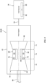
FIG. 1 is a schematic illustration of a powerplant system for an aircraft. -
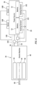
FIG. 2 is a schematic illustration of a power source configured with an electric machine, a heating system and a sensor system. -
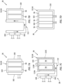
FIGS. 3A-D are schematic illustrations of various arrangements of the heating system configured with the power source. -
FIG. 4 is a schematic illustration of a single spool arrangement of the gas turbine engine configured with a fuel source. -
FIG. 5 is a schematic illustration of a multi-spool arrangement of the gas turbine engine configured with the fuel source. -
FIG. 6 is a schematic illustration of another arrangement of the power source configured with the electric machine, the heating system and the sensor system. -
FIGS. 7A-D are schematic illustrations of various additional arrangements of the heating system configured with the power source. -
FIG. 8 is a schematic illustration of a powerplant and the power source arranged within a common aircraft structure. -
FIG. 9 is a schematic illustration of the powerplant and the power source arranged within discrete aircraft structures. -
FIG. 10 is a schematic illustration of the powerplant system with the electric machine and the heat engine in a serial arrangement. -
FIG. 1 is a schematic illustration of apowerplant system 20 for an aircraft. Thispowerplant system 20 / aircraft system includes apowerplant powertrain 22, a (e.g., heat engine)fuel source 24, an (e.g., electric machine)electrical power source 26 and aheating system 28 for thepower source 26. - The
powertrain 22 includes amechanical load 30 and ahybrid powerplant 32, whichhybrid powerplant 32 includes anelectric machine 34 and aheat engine 36. Thepowertrain 22 ofFIG. 1 also includes a power transmission system 38 for transmitting mechanical power from thehybrid powerplant 32 to themechanical load 30. - The
mechanical load 30 may be configured as or otherwise include arotor 40 mechanically driven by anoutput shaft 42 and/or another torque transmission device. Themechanical load 30, for example, may be configured as a bladed propulsor rotor of a propulsor for an aircraft propulsion system. Examples of the propulsor rotor include, but are not limited to, a propeller for a propeller engine (e.g., a hybrid turboprop engine), a fan for a ducted fan engine (e.g., a hybrid turbofan engine), and a helicopter rotor (e.g., a main rotor) for a helicopter engine (e.g., a hybrid turboshaft engine). Themechanical load 30 may alternatively be configured as a generator rotor of an electrical power generator where, for example, thehybrid powerplant 32 is configured as a hybrid auxiliary power unit (APU). The present disclosure, however, is not limited to the foregoing exemplary mechanical loads nor the foregoing exemplary hybrid powerplant configurations. - The
electric machine 34 may be configurable as an electric motor and/or an electric generator. For example, during a motor mode of operation, theelectric machine 34 may operate as the electric motor to convert electricity received from thepower source 26 into mechanical power. This mechanical power may be utilized for various purposes within thehybrid powerplant 32 such as, for example, rotating themechanical load rotor 40 and/or rotating a rotatingassembly 43 within theheat engine 36 during heat engine startup. During a generator mode of operation, theelectric machine 34 may operate as the electric generator to convert mechanical power received from, for example, the heatengine rotating assembly 43 and/or themechanical load rotor 40 into electricity. This electricity may be utilized for various purposes within thehybrid powerplant 32 such as, for example, electrically powering one or more electric components of thehybrid powerplant 32 and/or charging thepower source 26. The electricity may also or alternatively be utilized for various purposes outside of thehybrid powerplant 32 such as, for example, electrically powering one or more electric components in the aircraft. - The
electric machine 34 ofFIG. 2 includes anelectric machine rotor 44 and an (e.g., annular)electric machine stator 46, where themachine stator 46 may be radially outboard of and circumscribe themachine rotor 44. Theelectric machine 34 also includes anelectric machine case 48 that at least partially or completely houses themachine rotor 44 and themachine stator 46. - The
power source 26 is electrically coupled with theelectric machine 34 through one or moreelectrical leads 50; e.g., high voltage lines. Thepower source 26 is configured to store electricity. Thepower source 26 is also configured to provide the stored electricity to theelectric machine 34 and/or receive electricity from theelectric machine 34; e.g., during recharging. Thepower source 26, for example, may be configured as or otherwise include a battery 52 (or multiple batteries 52). Referring toFIGS. 3A-D , thebattery 52 may be configured as or otherwise include a battery bank 54 with one ormore battery modules 56; e.g., battery cells. Thesemodules 56 may be arranged in a stack and electrically coupled to the electrical leads 50 in series or in parallel. - Referring to
FIG. 1 , theheat engine 36 is configured to convert chemical energy stored within fuel into mechanical power. Theheat engine 36 ofFIG. 4 , for example, is configured as or may otherwise include a gas turbine engine 58. The present disclosure, however, is not limited to such an exemplary heat engine. Theheat engine 36, for example, may alternatively be configured as or otherwise include a reciprocating piston internal combustion (IC) engine or a rotary internal combustion (IC) engine. However, for ease of description, theheat engine 36 may be described or referred to herein as the gas turbine engine 58. - The gas turbine engine 58 of
FIG. 4 includes the rotatingassembly 43, acombustor 60 and anengine case 62 housing the rotatingassembly 43 and thecombustor 60. The rotatingassembly 43 includes abladed compressor rotor 64, abladed turbine rotor 66 and ashaft 68 connecting thecompressor rotor 64 to theturbine rotor 66. Thecompressor rotor 64 is arranged in acompressor section 70 of the gas turbine engine 58. Theturbine rotor 66 is arranged within aturbine section 72 of the gas turbine engine 58. Thecombustor 60 is arranged within acombustor section 74 of the gas turbine engine 58. - The
fuel source 24 is configured to provide the fuel to the gas turbine engine 58 (the heat engine 36). Thefuel source 24 ofFIG. 4 , for example, is fluidly coupled with one ormore fuel injectors 76 of the gas turbine engine 58 through at least (or only) onefuel line 78. Thefuel source 24 is also configured to store (e.g., contain a quantity of) the fuel before, during and/or after heat engine operation. Thefuel source 24 ofFIG. 4 , for example, includes afuel reservoir 80 and afuel flow regulator 82. Thefuel flow regulator 82 may be or otherwise include a pump and/or a valve. Thisfuel flow regulator 82 is configured to direct fuel received from thefuel reservoir 80 to thefuel injectors 76 through thefuel line 78. - During operation of the gas turbine engine 58 of
FIG. 4 , air enters a gas path within the gas turbine engine 58 through an airflow inlet. The gas path extends sequentially through thecompressor section 70, thecombustor section 74 and theturbine section 72. This air is compressed by thecompressor rotor 64 and directed into acombustion chamber 84 of thecombustor 60. The fuel received by the gas turbine engine 58 from thefuel source 24 is injected into thecombustion chamber 84 by thefuel injectors 76 and mixed with the compressed air to provide a fuel-air mixture. This fuel-air mixture is ignited and combustion products thereof flow through and cause theturbine rotor 66 to rotate. The rotation of theturbine rotor 66 drives rotation of thecompressor rotor 64 and, thus, compression of the air received from the airflow inlet. The rotation of the rotatingassembly 43 also provides mechanical power for driving (e.g., rotating) themechanical load rotor 40 ofFIG. 1 . The gas turbine engine 58 of the present disclosure, however, is not limited to such an exemplary configuration. For example, referring toFIG. 5 , the gas turbine engine 58 may also include a free turbine 86 (e.g., a power turbine) that provides the mechanical power for driving themechanical load rotor 40 ofFIG. 1 . - The transmission system 38 of
FIG. 1 may be configured as or otherwise include a geartrain 88. This geartrain 88 is configured to motively couple / operatively connect theelectric machine 34 and theheat engine 36 to themechanical load 30 and itsrotor 40. An electric machine coupler 90 (e.g., a shaft), for example, rotatably couples theelectric machine 34 and its machine rotor 44 (e.g., see alsoFIG. 2 ) to afirst component 92 of the geartrain 88; e.g., a gear, a carrier, a shaft, etc. A heat engine coupler 94 (e.g., a shaft) rotatably couples theheat engine 36 and its rotating assembly 43 (e.g., see alsoFIGS. 4 and5 ) to asecond component 96 of the geartrain 88; e.g., a gear, a carrier, a shaft, etc. Theoutput shaft 42 rotatably couples themechanical load rotor 40 to athird component 98 of the geartrain 88; e.g., a gear, a carrier, a shaft, etc. Thesegeartrain components geartrain case 100 such that mechanical power may be transmitted through the transmission system 38, its geartrain 88 andgeartrain components electric machine 34 to themechanical load 30 and itsrotor 40; (2) from theheat engine 36 to themechanical load 30 and itsrotor 40; (3) from theheat engine 36 to theelectric machine 34; and/or (4) from theelectric machine 34 to theheat engine 36. - The
heating system 28 is configured heat thepower source 26 and, more particularly, its battery 52 (or batteries 52). Theheating system 28 ofFIG. 2 , for example, includes anelectric heating element 102 and a controller 104 (e.g., switch(s), a current regulator(s), etc.), where thebattery 52 is directly or indirectly thermally coupled with theelectric heating element 102. Theelectric heating element 102 may be configured as or otherwise include an electric coil and/or another heat producing electric resistor. Theelectric heating element 102 is electrically coupled with apower distribution system 106 for thehybrid powerplant 32, whichpower distribution system 106 electrically couples various electrical aircraft components together including, but not limited to, thesystem components electric heating element 102 ofFIG. 2 , for example, is electrically coupled to the electric machine 34 (e.g., when operating as the electric generator) through thecontroller 104. Thecontroller 104 may thereby selectively control (e.g., turn on, turn off or otherwise regulate) a flow of electrical power (e.g., electrical current) from the power distribution system 106 (e.g., the electric machine 34) to theelectric heating element 102. Theelectric heating element 102 may convert the received electrical power into thermal energy for heating thebattery 52. - During aircraft flight, the
power source 26 and itsbattery 52 may be subject to relatively cold ambient conditions; e.g., particularly where the aircraft is flying through cold weather and/or at a relatively high altitude. Such cold ambient conditions may cool thebattery 52 to a relatively cold temperature at which battery performance may degrade and/or thebattery 52 may begin to lose its electrical charge. Thebattery 52 may thereby not be ready for immediate use and/or optimum performance when needed, for example, to power theelectric machine 34 and/or various other aircraft electrical systems. - The
heating system 28 is configured to maintain a temperature of thebattery 52 at or above a temperature threshold. Theheating system 28, for example, may maintain a temperature of thebattery 52 within a temperature range; e.g., between a lower (e.g., minimum) temperature threshold and an upper (e.g., maximum) temperature threshold. Theheating system 28 may maintain or otherwise regulate battery temperature selectively during the aircraft flight and/or hybrid powerplant operation (e.g., when thebattery 52 is not being used, when thebattery 52 is not charging, when the aircraft is at a high altitude and/or at aircraft cruise) or throughout the aircraft flight and/or hybrid powerplant operation. - The
controller 104 may be in signal communication with a sensor system. The sensor system ofFIG. 2 includes a sensor 108 (or sensors) arranged with thepower source 26 and itsbattery 52. Thecontroller 104 may receive sensor data from thesensor 108, which the sensor data is indicative of a temperature of the environment in which thebattery 52 is stored and/or a temperature of thebattery 52. Thecontroller 104 may use this sensor data to control the flow of the electrical power to theelectric heating element 102. For example, where the temperature of thebattery 52 is at, close to or dips below its lower temperature threshold (or is predicted to be at, close to or dip below the lower temperature threshold), thecontroller 104 may direct (e.g., flow) the electrical power to theelectric heating element 102 to heat thebattery 52 until the temperature of thatbattery 52 is at, close to or rises above the upper temperature threshold (or is predicted to be at, close to or rise above the upper temperature threshold). This heated (e.g., temperature maintained)power source 26 /battery 52 may thereby remain ready for rapid (e.g., immediate) use and/or elevated (e.g., optimum) performance when needed. - The
heating system 28 may be operated when thebattery 52 is dormant. Theheating system 28, for example, may control the temperature of thebattery 52 when there is no (or very little) electrical power flowing into (e.g., charging) or out of (e.g., draining) thebattery 52. Under such operation, theheating system 28 may input all (or substantially all) of the heat energy used for regulating the battery temperature. Theheating system 28 may also or alternatively be operated when thebattery 52 is active. Theheating system 28, for example, may regulate the temperature of thebattery 52 when electrical power is flowing into (e.g., charging) or out of (e.g., draining) thebattery 52. When thebattery 52 is charging, the flow of the electrical power into thebattery 52 may contribute to the heating of thebattery 52. - In some embodiments, referring to
FIGS. 3A-C , theelectric heating element 102 may be disposed outside of thebattery 52. Theelectric heating element 102 ofFIG. 3A , for example, is disposed next to thebattery 52. More particularly, theelectric heating element 102 may be mounted on / to a side of a case 110 (e.g., a module housing) in which thebattery modules 56 are contained. Thiselectric heating element 102 is thermally coupled with any one or more or all of thebattery modules 56 through thebattery case 110. In another example, referring toFIGS. 3B and 3C , theelectric heating element 102 is thermally coupled to thebattery 52 and itsbattery modules 56 through a (e.g., heating and/or cooling)fluid circuit 112. Theelectric heating element 102, for example, may be located remote from thebattery 52. During operation, theelectric heating element 102 transfers heat energy into (e.g., heats) fluid flowing through thefluid circuit 112, where the fluid may be a liquid and/or a gas. The heated fluid subsequently transfers heat energy into (e.g., heats) any one or more or all of the battery modules 56 (A) indirectly, for example, through the battery case 110 (seeFIG. 3B ) and/or (B) directly where thefluid circuit 112 includes one ormore segments 113A-C (generally referred to as "113") within the battery case 110 (seeFIG. 3C ) and, for example, around and/or between thebattery modules 56. Thisfluid circuit 112 may also be utilized for cooling thepower source 26 and itsbattery 52 during other modes of operation; e.g., when thebattery 52 is being rapidly charged by theelectric machine 34 or anotherpower source 26. - In some embodiments, referring to
FIG. 3D , the electric heating element(s) 102 may be disposed within (e.g., integrated into) thebattery 52. Theelectric heating element 102 ofFIG. 3D , for example, is located within thebattery 52 and itsbattery case 110. Theelectric heating element 102 may be next to (e.g., on / to a side of) and thermally coupled with one or more of thebattery modules 56. Theelectric heating element 102 ofFIG. 3D , for example, is disposed laterally between an adjacent (e.g., neighboring) pair of thebattery modules 56 within thebattery 52. - In some embodiments, referring to
FIG. 2 , thepower source 26 may include a single battery 52 (without optional dashed line battery). In other embodiments, referring toFIG. 6 , thepower source 26 may include a plurality of thebatteries 52. Each of thesebatteries 52 may be configured with a respectiveelectric heating element 102 for controlling the temperature of thatrespective battery 52. - In some embodiments, referring to
FIGS. 3A-D , eachbattery 52 may be associated with a singleelectric heating element 102. In other embodiments, referring toFIGS. 7A-D , eachbattery 52 may be associated with a plurality of theelectric heating elements 102. - In some embodiments, the battery modules 56 (and optionally the electric heating element(s) 102) may be disposed within the
battery case 110 without insulation. In other embodiments, the battery modules 56 (and optionally the electric heating element(s) 102) may be disposed within thebattery case 110 with insulation. This insulation may extend about an outer periphery of the stack ofbattery modules 56. The insulation may also or alternatively extend about an outer periphery of the battery case 110 (and optionally the electric heating element(s) 102). - In some embodiments, referring to
FIG. 8 , thehybrid powerplant 32 and thepower source 26 may be arranged / contained within acommon housing 114. In other embodiments, referring toFIG. 9 , thehybrid powerplant 32 may be remotely located from thepower source 26. Thehybrid powerplant 32 ofFIG. 9 , for example, is housed within a first component /structure 116 of the aircraft; e.g., a propulsion system nacelle. Thepower source 26 ofFIG. 9 is housed within a second component /structure 118 of the aircraft; e.g., an aircraft wing or an aircraft fuselage. - In some embodiments, referring to
FIG. 1 , theelectric machine 34 and theheat engine 36 may be configured in parallel to drive themechanical load 30 and itsrotor 40 through the transmission system 38 and its geartrain 88. In other embodiments, referring toFIG. 10 , theelectric machine 34 and theheat engine 36 may be configured in series to drive themechanical load 30 and itsrotor 40. Themechanical load 30 and itsrotor 40 ofFIG. 10 , for example, is operably coupled to theelectric machine 34 serially through the transmission system 38 / the geartrain 88 and theheat engine 36. The present disclosure, however, is not limited to such an exemplary arrangement. - While various embodiments of the present disclosure have been described, it will be apparent to those of ordinary skill in the art that many more embodiments and implementations are possible within the scope of the disclosure. For example, the present disclosure as described herein includes several aspects and embodiments that include particular features. Although these features may be described individually, it is within the scope of the present disclosure that some or all of these features may be combined with any one of the aspects and remain within the scope of the disclosure. Accordingly, the present disclosure is not to be restricted except in light of the attached claims and their equivalents.
Claims (15)
- A system (20) for an aircraft, comprising:a rotor (40);a powerplant (32) configured to drive rotation of the rotor (40), the powerplant (32) including a heat engine (36) and an electric machine (34);a battery (52) electrically coupled with the electric machine (34); anda heating system (28) comprising an electric heating element (102), the heating system (28) configured to heat the battery (52) using the electric heating element (102).
- The system (20) of claim 1, wherein the heating system (28) is configured to maintain a temperature of the battery (52) at or above a threshold.
- The system (20) of claim 1 or 2, wherein the heating system (28) is configured to heat the battery (52) using the electric heating element (102) during aircraft flight.
- The system (20) of claim 1, 2 or 3, wherein the electric machine (34) is configurable as at least one of:an electric motor during a motor mode of operation, wherein, optionally, the electric machine (34) is configured to receive electrical power from the battery (52) during the motor mode of operation; andan electric generator during a generator mode of operation, wherein, optionally, the electric machine (34) is configured to provide electrical power to the battery (52) during the generator mode of operation.
- The system (20) of any preceding claim, wherein the heating system (28) is configured to receive electrical power from the electric machine (34) to electrically power the electric heating element (102).
- The system (20) of claim 1, wherein the electric heating element (102) is next to and thermally coupled with the battery (52).
- The system (20) of any of claims 1 to 5, wherein the electric heating element (102) is integrated within the battery (52), and/or wherein the battery (52) comprises a battery pack (54) with a plurality of modules (56) and the electric heating element (102) is between an adjacent pair of the plurality of modules (56).
- The system (20) of any of claims 1 to 6, wherein the electric heating element (102) is thermally coupled with the battery (52) through a fluid circuit (112).
- The system (20) of any preceding claim, whereinthe heating system (28) further comprises a second electric heating element (102); andthe heating system (28) is configured to heat the battery (52) using the electric heating element (102) and the second electric heating element (102).
- The system (20) of any preceding claim, further comprising a geartrain (88) mechanically coupling at least one of the heat engine (36) and the electric machine (34) to the rotor (40).
- The system (20) of any preceding claim, wherein the heat engine (36) comprises a gas turbine engine (58), and/or the rotor (40) comprises a propulsor rotor.
- The system (20) of any preceding claim, further comprising:an aircraft fuselage, the battery (52) arranged within the aircraft fuselage; anda propulsion system nacelle housing the powerplant (32).
- A method for an aircraft system (20), the method comprising:driving a propulsor using a hybrid powerplant (32) during aircraft flight; andmaintaining a temperature of a battery (52) at or above a threshold during the aircraft flight using an electric heating element (102).
- The method of claim 13, wherein the battery (52) is electrically coupled with an electric machine (34) within the hybrid powerplant (32).
- The method of claim 13 or 14, further comprising providing electrical power to the electric heating element (102) from an electric machine (34) within the hybrid powerplant (32).
Applications Claiming Priority (1)
| Application Number | Priority Date | Filing Date | Title |
|---|---|---|---|
| US17/733,408 US20230352760A1 (en) | 2022-04-29 | 2022-04-29 | Electrical heating system for hybrid powerplant electrical power source |
Publications (1)
| Publication Number | Publication Date |
|---|---|
| EP4269250A1 true EP4269250A1 (en) | 2023-11-01 |
Family
ID=86272215
Family Applications (1)
| Application Number | Title | Priority Date | Filing Date |
|---|---|---|---|
| EP23170431.3A Pending EP4269250A1 (en) | 2022-04-29 | 2023-04-27 | Electrical heating system for hybrid powerplant electrical power source |
Country Status (3)
| Country | Link |
|---|---|
| US (1) | US20230352760A1 (en) |
| EP (1) | EP4269250A1 (en) |
| CA (1) | CA3198124A1 (en) |
Cited By (1)
| Publication number | Priority date | Publication date | Assignee | Title |
|---|---|---|---|---|
| DE102024210862A1 (en) * | 2024-11-12 | 2026-05-13 | Volkswagen Aktiengesellschaft | Thermal management system and motor vehicle with a thermal management system |
Citations (9)
| Publication number | Priority date | Publication date | Assignee | Title |
|---|---|---|---|---|
| US20160072161A1 (en) * | 2014-09-09 | 2016-03-10 | Google Inc. | Battery pack with embedded heaters |
| US20190128570A1 (en) * | 2017-11-02 | 2019-05-02 | Rolls-Royce Plc | Thermal management system |
| JP2020510954A (en) * | 2017-01-19 | 2020-04-09 | ナショナル・リサーチ・カウンシル・オブ・カナダNational Research Council Of Canada | Apparatus and method for causing thermal runaway in a battery |
| US20200130534A1 (en) * | 2018-10-26 | 2020-04-30 | Pratt & Whitney Canada Corp. | Battery heating in hybrid electric power plant |
| US20200303788A1 (en) * | 2019-03-20 | 2020-09-24 | Hamilton Sundstrand Corporation | Thermal regulation of batteries |
| US20210143657A1 (en) * | 2019-11-07 | 2021-05-13 | Rolls-Royce Plc | Electrical Power Supply System |
| US20210143492A1 (en) * | 2019-11-13 | 2021-05-13 | Rolls-Royce Plc | Battery Thermal Regulating Unit |
| JP2022045996A (en) * | 2020-09-10 | 2022-03-23 | 愛三工業株式会社 | Helicopter |
| CN216154049U (en) * | 2021-08-31 | 2022-04-01 | 上海动力储能电池系统工程技术有限公司 | Compatible light-storage integrated power supply device for unmanned aerial vehicle and unmanned aerial vehicle |
Family Cites Families (15)
| Publication number | Priority date | Publication date | Assignee | Title |
|---|---|---|---|---|
| GB1230591A (en) * | 1967-10-14 | 1971-05-05 | ||
| US3649366A (en) * | 1970-02-19 | 1972-03-14 | Esb Inc | Storage battery and heater therefor |
| GB1544455A (en) * | 1975-06-03 | 1979-04-19 | Miyahara H | Secondary battery charger |
| US4762978A (en) * | 1986-07-22 | 1988-08-09 | Tanis Peter G | Aircraft battery assembly |
| US5281792A (en) * | 1991-08-30 | 1994-01-25 | Rj Lee Group, Inc. | Battery warmer |
| US20060016793A1 (en) * | 2004-07-23 | 2006-01-26 | Douglas Zhu | Electrical storage device heater for vehicle |
| JP5664690B2 (en) * | 2013-03-29 | 2015-02-04 | 株式会社豊田自動織機 | Battery pack |
| US9831534B2 (en) * | 2013-10-18 | 2017-11-28 | Textron Innovations Inc. | Lithium ion battery heater systems and methods |
| US11623757B2 (en) * | 2018-06-08 | 2023-04-11 | Embraer S.A. | Hybrid electric taxi system (HETS) or full electric taxi system (FETS) |
| KR102506814B1 (en) * | 2018-12-21 | 2023-03-09 | 한국전자기술연구원 | Battery heater module for cold start and battery system comprising the same |
| US11133537B2 (en) * | 2018-12-31 | 2021-09-28 | Textron Inc. | Performing temperature control on a lithium battery of a vehicle |
| WO2020180370A1 (en) * | 2019-03-01 | 2020-09-10 | United Technologies Advanced Projects Inc. | Aircraft propulsion system having hybrid-electric powerplant and combustion powerplant |
| EP3750793B1 (en) * | 2019-06-14 | 2023-04-05 | Hamilton Sundstrand Corporation | Aircraft having hybrid-electric propulsion system with electric storage located in fuselage |
| GB202008070D0 (en) * | 2020-05-29 | 2020-07-15 | Rolls Royce Plc | Aircraft electrical power distribution |
| DE102020209492A1 (en) * | 2020-07-28 | 2022-02-03 | Robert Bosch Gesellschaft mit beschränkter Haftung | Heated battery module |
-
2022
- 2022-04-29 US US17/733,408 patent/US20230352760A1/en active Pending
-
2023
- 2023-04-27 CA CA3198124A patent/CA3198124A1/en active Pending
- 2023-04-27 EP EP23170431.3A patent/EP4269250A1/en active Pending
Patent Citations (9)
| Publication number | Priority date | Publication date | Assignee | Title |
|---|---|---|---|---|
| US20160072161A1 (en) * | 2014-09-09 | 2016-03-10 | Google Inc. | Battery pack with embedded heaters |
| JP2020510954A (en) * | 2017-01-19 | 2020-04-09 | ナショナル・リサーチ・カウンシル・オブ・カナダNational Research Council Of Canada | Apparatus and method for causing thermal runaway in a battery |
| US20190128570A1 (en) * | 2017-11-02 | 2019-05-02 | Rolls-Royce Plc | Thermal management system |
| US20200130534A1 (en) * | 2018-10-26 | 2020-04-30 | Pratt & Whitney Canada Corp. | Battery heating in hybrid electric power plant |
| US20200303788A1 (en) * | 2019-03-20 | 2020-09-24 | Hamilton Sundstrand Corporation | Thermal regulation of batteries |
| US20210143657A1 (en) * | 2019-11-07 | 2021-05-13 | Rolls-Royce Plc | Electrical Power Supply System |
| US20210143492A1 (en) * | 2019-11-13 | 2021-05-13 | Rolls-Royce Plc | Battery Thermal Regulating Unit |
| JP2022045996A (en) * | 2020-09-10 | 2022-03-23 | 愛三工業株式会社 | Helicopter |
| CN216154049U (en) * | 2021-08-31 | 2022-04-01 | 上海动力储能电池系统工程技术有限公司 | Compatible light-storage integrated power supply device for unmanned aerial vehicle and unmanned aerial vehicle |
Cited By (1)
| Publication number | Priority date | Publication date | Assignee | Title |
|---|---|---|---|---|
| DE102024210862A1 (en) * | 2024-11-12 | 2026-05-13 | Volkswagen Aktiengesellschaft | Thermal management system and motor vehicle with a thermal management system |
Also Published As
| Publication number | Publication date |
|---|---|
| CA3198124A1 (en) | 2023-10-29 |
| US20230352760A1 (en) | 2023-11-02 |
Similar Documents
| Publication | Publication Date | Title |
|---|---|---|
| US10435169B2 (en) | Hybrid electric drive train for VTOL drones | |
| JP5923515B2 (en) | Power generation control method used for aircraft gas turbine and apparatus for implementing the method | |
| US11939073B2 (en) | Starting methods for hybrid-electric aircraft | |
| EP3643889A1 (en) | Battery heating in hybrid electric power plant | |
| US12145738B2 (en) | Multi-drive unit propulsion system for an aircraft | |
| EP4311777A1 (en) | Multi-drive unit powerplant for an aircraft | |
| US20240425188A1 (en) | Testing secondary power system of aircraft powerplant | |
| EP4501791A1 (en) | Containment zone for an electric machine in a hybrid powerplant for an aircraft | |
| US20230352760A1 (en) | Electrical heating system for hybrid powerplant electrical power source | |
| EP4303127A1 (en) | Hybrid-electric aircraft propulsion system and method | |
| EP4223644A1 (en) | Containment zone for an electric machine in a hybrid powerplant for an aircraft | |
| EP4567263A1 (en) | Compressed air system for aircraft | |
| US12583596B2 (en) | Aircraft propulsion system | |
| US12398678B2 (en) | Motor and motor controller thermal management features | |
| EP4506257A1 (en) | Power management between a heat engine and an electric machine for an aircraft powerplant | |
| US12163468B1 (en) | Aircraft powerplant with electric transmission(s) | |
| US20250043733A1 (en) | Hybrid turbofan engine with a planetary gearset for blending power between an electric output and variable-thrust bypass fan | |
| US12523161B1 (en) | Aircraft powerplant gearbox with selectable power coupler | |
| US12529340B2 (en) | Emergency start of a gas turbine engine | |
| US20250035043A1 (en) | Emergency start of a gas turbine engine | |
| US20260139627A1 (en) | Emergency start of a gas turbine engine |
Legal Events
| Date | Code | Title | Description |
|---|---|---|---|
| PUAI | Public reference made under article 153(3) epc to a published international application that has entered the european phase |
Free format text: ORIGINAL CODE: 0009012 |
|
| STAA | Information on the status of an ep patent application or granted ep patent |
Free format text: STATUS: THE APPLICATION HAS BEEN PUBLISHED |
|
| AK | Designated contracting states |
Kind code of ref document: A1 Designated state(s): AL AT BE BG CH CY CZ DE DK EE ES FI FR GB GR HR HU IE IS IT LI LT LU LV MC ME MK MT NL NO PL PT RO RS SE SI SK SM TR |
|
| STAA | Information on the status of an ep patent application or granted ep patent |
Free format text: STATUS: REQUEST FOR EXAMINATION WAS MADE |
|
| 17P | Request for examination filed |
Effective date: 20240501 |
|
| RBV | Designated contracting states (corrected) |
Designated state(s): AL AT BE BG CH CY CZ DE DK EE ES FI FR GB GR HR HU IE IS IT LI LT LU LV MC ME MK MT NL NO PL PT RO RS SE SI SK SM TR |
|
| STAA | Information on the status of an ep patent application or granted ep patent |
Free format text: STATUS: EXAMINATION IS IN PROGRESS |
|
| 17Q | First examination report despatched |
Effective date: 20250227 |