EP4269248A1 - Ice protection system including frequency dependent susceptor - Google Patents
Ice protection system including frequency dependent susceptor Download PDFInfo
- Publication number
- EP4269248A1 EP4269248A1 EP23170213.5A EP23170213A EP4269248A1 EP 4269248 A1 EP4269248 A1 EP 4269248A1 EP 23170213 A EP23170213 A EP 23170213A EP 4269248 A1 EP4269248 A1 EP 4269248A1
- Authority
- EP
- European Patent Office
- Prior art keywords
- frequency
- susceptor
- energy
- protection system
- absorbing mode
- Prior art date
- Legal status (The legal status is an assumption and is not a legal conclusion. Google has not performed a legal analysis and makes no representation as to the accuracy of the status listed.)
- Pending
Links
Images




Classifications
-
- B—PERFORMING OPERATIONS; TRANSPORTING
- B64—AIRCRAFT; AVIATION; COSMONAUTICS
- B64D—EQUIPMENT FOR FITTING IN OR TO AIRCRAFT; FLIGHT SUITS; PARACHUTES; ARRANGEMENT OR MOUNTING OF POWER PLANTS OR PROPULSION TRANSMISSIONS IN AIRCRAFT
- B64D15/00—De-icing or preventing icing on exterior surfaces of aircraft
- B64D15/12—De-icing or preventing icing on exterior surfaces of aircraft by electric heating
Definitions
- the present disclosure relates to de-icing systems, and more particularly, to aircraft ice protection systems for preventing or reducing the icing of an aerodynamic surface.
- Aircrafts implement ice protection system to prevent and/or remove ice accumulation on a critical surface of the aircraft such as for example, a wing, horizontal stabilizer, engine, pylons, and/or a blade to name a few surfaces.
- Aircraft ice protection systems include both electrical de-icing systems and non-electrical de-icing systems.
- Electrical de-icing systems are known to implement a wire or wire mesh structure that is embedded within the critical surface or wrapped around the critical surface.
- the non-electrical de-icing systems include pneumatic ice protection systems, for example, which use hot air to heat a targeted surface to prevent ice formation. Electrical current is then delivered through the wire or wire mesh to produce heat. The heat, if sufficient, can melt or "shed" collected ice from the critical surface and/or prevent the accretion of ice on the critical surface.
- an aircraft ice protection system includes a frequency dependent susceptor coupled to a critical surface of an aircraft, and a radio frequency (RF) energy source configured to apply RF energy to the frequency dependent susceptor.
- the aircraft ice protection system is configured to selectively operate in a susceptor absorbing mode and a water absorbing mode.
- the RF energy source delivers the RF energy having a first frequency to the frequency dependent susceptor in response to operating in the susceptor absorbing mode, and delivers the RF energy having a different second frequency to the frequency dependent susceptor in response to operating in the water absorbing mode.
- the RF energy having the first frequency attenuates the frequency dependent susceptor to emit heat therefrom, and wherein the RF energy having the second frequency is transmitted from the frequency dependent susceptor to attenuate a Faraday layer defining a layer of liquid water formed on ice present on the critical surface.
- the first frequency falls within a frequency range that includes a first attenuation frequency of a material of the frequency dependent susceptor, and wherein the second frequency falls within a second range that includes a second attenuation frequency of the liquid water.
- the first frequency is different from the second frequency.
- a controller is in signal communication with the radio frequency (RF) energy source, the controller configured to selectively invoke the susceptor absorbing mode and the water absorbing mode.
- RF radio frequency
- the controller is configured to switch from the susceptor absorbing mode to the water absorbing mode in response to determining the Faraday layer has a target characteristic.
- the controller determines a time period during which the RF energy having the first frequency is delivered to the frequency dependent susceptor, and determines the Faraday layer has the target characteristic in response to the time period exceeding a time period threshold.
- the controller determines scattering parameters of the RF energy having the first frequency and determines one or both of a transmission coefficient and a reflection coefficient of the RF energy having the first frequency, and wherein the controller determines the Faraday layer has the target characteristic in response to one or both of the transmission coefficient being less than a transmission coefficient threshold or the reflection coefficient being greater than a reflection coefficient threshold.
- At least one dielectric layer covers the critical surface.
- the frequency dependent susceptor includes a thin dielectric layer having an upper surface and an opposing lower surface, and wherein at least one of the upper and lower surfaces includes a patterned metallic structure configured to define an absorbance and transmittance response with respect to a frequency of applied RF energy.
- a method for removing ice from a critical surface of an aircraft.
- the method includes applying, by a radio frequency (RF) energy source, RF energy to a frequency dependent susceptor coupled to the critical surface; selectively operating the aircraft ice protection system in a susceptor absorbing mode and a water absorbing mode; and removing the ice from the critical surface based on the susceptor absorbing mode and a water absorbing mode.
- RF radio frequency
- the method further includes delivering, by the RF energy source, the RF energy having a first frequency to the frequency dependent susceptor in response to operating in the susceptor absorbing mode; and delivering the RF energy having a different second frequency to the frequency dependent susceptor in response to operating in the water absorbing mode.
- the method further includes attenuating the frequency dependent susceptor using the RF energy having the first frequency attenuates to emit heat therefrom; and transmitting the RF energy having the second frequency from the frequency dependent susceptor to attenuate a Faraday layer defining a layer of liquid water formed on ice present on the critical surface.
- the method further includes a feature, wherein the first frequency falls within a frequency range that includes a first attenuation frequency of a material of the frequency dependent susceptor, and wherein the second frequency falls within a second range that includes a second attenuation frequency of the liquid water.
- the method further includes a feature wherein the first frequency is different from the second frequency.
- the method further includes determining a target characteristic of the Faraday layer; detecting the Faraday layer achieves the target characteristic in response to delivering the RF energy having a first frequency during the susceptor absorbing mode; and switching from the susceptor absorbing mode to the water absorbing mode in response to detecting the Faraday layer has the target characteristic.
- the method further includes determining a time period during which the RF energy having the first frequency is delivered to the frequency dependent susceptor; and determining the Faraday layer has the target characteristic in response to the time period exceeding a time period threshold.
- the method further includes determining scattering parameters of the RF energy having the first frequency; determining one or both of a transmission coefficient and a reflection coefficient of the RF energy having the first frequency; and determining the Faraday layer has the target characteristic in response to one or both of the transmission coefficient being less than a transmission coefficient threshold or the reflection coefficient being greater than a reflection coefficient threshold.
- the method further includes a feature wherein the frequency dependent susceptor includes a thin dielectric layer having an upper surface and an opposing lower surface, and wherein at least one of the upper and lower surfaces includes a patterned metallic structure configured to define an absorbance and transmittance response with respect to a frequency of applied RF energy.
- ice does not necessarily consist of a single solid state of mass, but rather can include a quasi-liquid layer formed on the surface of the ice.
- This quasi-liquid layer is referred to as "the Faraday layer” and has been found to exist at temperatures even as low as -38 degrees Celsius (235 Kelvin). As the temperature of the solid ice portion increases, the thickness of the Faraday layer increases thereby contributing to melting and removal of ice.
- Liquid water is capable of absorbing radio frequency (RF) energy and resonates at various frequencies such as, for example, about 22 gigahertz (GHz) or about 60 GHz.
- RF radio frequency
- the amount of energy absorbed by attenuated liquid water increases exponentially as the thickness of the liquid water increases. For instance, liquid water having a thickness of about 0.01 millimeters (mm) absorbs about 0% of the attenuated energy, while liquid water having a thickness of about 1.0 mm absorbs about 16% of the attenuated energy and liquid water having a thickness of about 1.0 mm absorbs about 16% of the attenuated energy and 10.0 mm absorbs about 70% of the attenuated energy.
- the Faraday layer is extremely thin (e.g., less than about 0.01 millimeters).
- an aircraft ice protection system that includes a frequency dependent susceptor that is configured to change behavior based on the frequency of the RF energy applied thereto by a RF energy source included in the aircraft ice protection system.
- the frequency dependent susceptor allows for more efficiently heat the Faraday layer at low environmental temperatures.
- the frequency dependent susceptor therefore allows the aircraft ice protection system to selectively operate in a susceptor absorbing mode and a water absorbing mode.
- the RF energy source delivers RF energy having a first frequency to the frequency dependent susceptor. Accordingly, the frequency dependent susceptor absorbs more energy than it transmits, thereby emitting heat that increases the thickness of the Faraday layer.
- the ice protection system initiates the water absorbing mode.
- the RF energy source delivers RF energy having a different second frequency capable of fully or at least partially passing through the frequency dependent susceptor 54, while still capable of heating the liquid water of the increased Faraday layer 50.
- the second frequency of the RF energy causes the frequency dependent susceptor to transmit more RF energy than it absorbs. That is, the second frequency allows the RF energy to fully, or at least partially pass through, the frequency dependent susceptor such that a substantial amount of the RF energy is passed through.
- the second frequency of the transmitted RF energy is set such that the RF energy substantially is absorbed by the Faraday layer causing it to absorb heat and melt the underlying ice.
- the ice protection systems 12 include a frequency dependent susceptor and a radio frequency (RF) supply, each which are described in greater detail below.
- the frequency dependent susceptor includes a susceptor material which has a high absorption at one frequency but not another, thereby permitting selective absorption by the susceptor to grow the Faraday layer corresponding to ice formed thereon.
- the frequency dependent susceptor can operate at any frequency above 1 GHz so long as it is designed to have a microwave "window" to allow selective heating of the Faraday layer.
- the RF supply can be operated to deliver RF energy to the frequency dependent susceptor and the controller 14 controls the RF supply to adjust the output RF energy level and/or RF frequency.
- the ice protection systems 12 are shown disposed on the wings 16 of the aircraft 10. It should be appreciated, however, that they could additionally or alternatively be secured to other critical surfaces of the aircraft 10 including, but not limited to, other airfoils, stabilizers, engine inlets, and rotors, along with and other ice-susceptible aircraft components.
- a plurality of individual ice protection systems 12a, 12b, 12c are formed on an aircraft wing 16 according to a non-limiting embodiment.
- a wing 16 is described, it should be apricated that the ice protection systems 12a, 12b, 12c can be utilized to remove ice from other types of critical surfaces without departing from the scope of the inventive teachings.
- the wing 16 includes an upper surface 20, a lower surface 22, and a leading edge 23.
- a first ice protection system 12a is formed on the wing upper surface 20
- a second ice protection system 12b is formed on the wing leading edge 23, and a third ice protection system 12c is formed on the wing lower surface 22.
- three individual ice protection system 12a-12c are illustrated, it should be appreciated that a single ice protection system 12 can be utilized that extends continuously across the wing upper surface 20, the wing leading edge 23, and the wing lower surface 22.
- the wing 16 is further shown having a first accumulation of ice 25 covering the wing upper surface 20 and a second accumulation of ice 27 covering the leading edge 23.
- a layer of liquid-like water referred herein as a "Faraday layer.”
- a first Faraday layer 26 of liquid water is interposed between the first accumulation of ice 25 and the first ice protection system 12a, while a second Faraday layer 28 of liquid water is interposed between the second accumulation of ice 27 and the second ice protection system 12b.
- an RF energy supply 15 is illustrated in signal communication with each of the ice protection systems 12a, 12b and 12c.
- the RF energy source 15 is configured to deliver RF energy to the ice protection systems 12a, 12b and 12c.
- the controller 14 is in signal communication with the RF energy supply 15.
- the controller 14 is configured to selectively operate the RF energy source 15 according to a susceptor absorbing mode and a water absorbing mode.
- the RF energy source 15 When operating in the susceptor absorbing mode, the RF energy source 15 outputs RF energy having a first frequency set according to a material of the susceptor to allow the a frequency dependent susceptor to substantially absorb the RF energy.
- the RF energy source 15 When operating in the water absorbing mode, the RF energy source 15 outputs RF energy having a second frequency different from the first frequency to fully or at least partially pass through the frequency dependent susceptor and heat the liquid water of the increased Faraday layer.
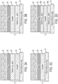
- FIGS. 3A, 3B, 3C and 3D illustrate the aircraft ice protection system 12 according to various non-limiting embodiments.
- the aircraft ice protection system 12 is interposed between a critical surface 16 (e.g., awing) and a combination of ice 52 and a Faraday layer of liquid water 50 covering the critical surface 16.
- the aircraft ice protection system 12 includes a frequency dependent susceptor 54 disposed on an upper surface of the critical surface 16 and a dielectric layer 56 disposed on an upper surface of the frequency dependent susceptor 54.
- the ice 52 covers the ice protection system 12 with the Faraday layer of liquid water 50 formed directly on an upper surface of the dielectric layer 56.
- the dielectric layer 56 can include, but is not limited to glass or fiber glass.
- the frequency dependent susceptor 54 includes a thin dielectric layer having an upper surface and an opposing lower surface. At least one of the upper surface and the lower surface includes a patterned metallic structure configured to define an absorbance and transmittance response with respect to a frequency of applied RF energy. In this manner, the frequency dependent susceptor 54 can be tuned to attenuate according to a targeted frequency of RF energy.
- the aircraft ice protection system 12 is interposed between a critical surface 16 (e.g., a wing) and a combination of ice 52 and a Faraday layer of liquid water 50 covering the critical surface 16.
- the aircraft ice protection system 12 includes a dielectric layer 56 disposed on an upper surface of the critical surface 16 and a frequency dependent susceptor 54 disposed on an upper surface of the dielectric layer 56. Accordingly, the ice 52 covers the ice protection system 12 with the Faraday layer of liquid water 50 formed directly on an upper surface of the frequency dependent susceptor 54.
- the aircraft ice protection system 12 is interposed between a critical surface 16 (e.g., a wing) and a combination of ice 52 and a Faraday layer of liquid water 50 covering the critical surface 16.
- the aircraft ice protection system 12 includes a frequency dependent susceptor 54 disposed on an upper surface of the critical surface 16, but excludes a dielectric layer. Accordingly, the ice 52 covers the ice protection system 12 with the Faraday layer of liquid water 50 formed directly on an upper surface of the frequency dependent susceptor 54.
- the aircraft ice protection system 12 is interposed between a critical surface 16 (e.g., a wing) and a combination of ice 52 and a Faraday layer of liquid water 50 covering the critical surface 16.
- the aircraft ice protection system 12 includes a frequency dependent susceptor 54 interposed between a first dielectric layer 56a and a second dielectric layer 56b.
- the first dielectric layer 56a is disposed on an upper surface of the critical surface 16.
- the ice 52 covers the ice protection system 12 with the Faraday layer of liquid water 50 formed directly on an upper surface of the s second dielectric layer 56b.
- the ice protection system 12 is illustrated selectively controlled to operate in two different operating modes according to non-limiting embodiments of the present teachings.
- the two operating modes i.e., a susceptor absorbing mode and a water absorbing mode
- the ice protection system 12 is shown operating in the susceptor absorbing mode to perform the first step.
- the controller 14 controls the RF energy source 15 to output RF energy 60 having a first frequency set to attenuate the frequency dependent susceptor 54.
- the first frequency is about 2.5 GHz.
- the frequency dependent susceptor 54 absorbs more energy than it transmits.
- the frequency dependent susceptor 54 converts the RF energy 60 output from the RF energy source 15 into thermal energy 62 (e.g., heat), which melts the ice 52 and creates a larger Faraday layer 50 (i.e., increases the thickness of the Faraday layer 50) at the surface of the ice 52.
- thermal energy 62 e.g., heat
- the ice protection system 12 is shown after switching from the susceptor absorbing mode to the water absorbing mode.
- the controller 14 controls the RF energy source 15 to output RF energy 60 having a second frequency set to fully or at least partially pass through the frequency dependent susceptor 54, while still capable of attenuating the liquid water of the increased Faraday layer 50.
- the second frequency is about 22 GHz, but it should be appreciated that other frequencies capable of allowing the RF to pass through the selected material of the frequency dependent susceptor 54 can be utilized without departing from the scope of the invention.
- the frequency dependent susceptor 54 passes the RF energy 60 therethrough and effectively transmits it to the Faraday layer 50. Accordingly, the increased thickness of the water now allows the Faraday layer 50 to effectively absorb the RF energy 60 and convert it into thermal energy 62 (e.g., heat) that continues to melt the ice 52 and leads to removing it from the critical surfaced 16.
- thermal energy 62 e.g., heat
- the controller 14 is configured to switch from the susceptor absorbing mode to the water absorbing mode in response to determining the Faraday layer 50 has reached a target characteristic or property.
- the target characteristic or property can include a target thickness (e.g., greater than or equal to 1.0 mm), or a target absorptive property.
- the controller 14 can determine a time period during which the RF energy 60 having the first frequency is delivered to the frequency dependent susceptor 54. Accordingly, the controller determines the Faraday layer 50 has reached the target characteristic or property in response to the time period exceeding a time period threshold.
- the controller 14 determines scattering parameters (often referred to as "S-parameters") of the RF energy 60 having the first frequency and determines one or both of a transmission coefficient and a reflection coefficient of the RF energy 60 having the first frequency. Accordingly, the controller 14 determines the Faraday layer 50 has reached the target characteristic or property in response to the transmission coefficient being less than a transmission coefficient threshold and/or the reflection coefficient being greater than a reflection coefficient threshold.
- the characteristic or property can include, for example, a target thickness (e.g., greater than or equal to 1.0 mm), or a target absorptive property.
- a method of removing ice from a critical surface of an aircraft begins at operation 600 and at operation 602 a susceptor absorbing mode of an ice protection system installed on the aircraft is initiated.
- an RF energy source delivers RF energy having a first frequency is delivered to a frequency dependent susceptor included in the ice protection system.
- the RF energy has a frequency (e.g., 2.5 GHz) that is set to attenuate the frequency dependent susceptor.
- the frequency dependent susceptor absorbs the RF energy having the first frequency and converts it into thermal energy.
- the thermal energy is emitted from the frequency dependent susceptor and delivered to the ice covering the critical surface such that the ice begins to melt thereby increasing the thickness of the liquid water defining the Faraday layer associated with the ice.
- a determination is made as to whether the characteristic or property of the Faraday layer reaches a target characteristic or property.
- the target specification or property can include a target thickness.
- the method proceeds to operation 612 and initiates a water absorbing mode of the ice protection system.
- the RF energy source delivers RF energy having a second frequency that allows the RF energy to fully or at least partially pass through the frequency dependent susceptor 54, while still capable of heating the liquid water of the increased Faraday layer 50.
- the RF energy has a frequency that is set to attenuate the water of the Faraday layer rather than the frequency dependent susceptor.
- the second frequency is set to about 22 GHz, but it should be appreciated that other frequencies capable of allowing the RF to pass through the selected material of the frequency dependent susceptor 54 can be utilized without departing from the scope of the invention.
- the frequency dependent susceptor passes the RF energy having the second frequency and transmits it (e.g., passes it through) to the Faraday layer defined by the increased thickness of water.
- the water of the Faraday layer absorbs the RF energy having the second frequency and converts it into thermal energy.
- the thermal energy is emitted from the Faraday layer and continues melting the ice such that it is ultimately removed from the critical surface.
- the method ends.
- the terms may include a range of ⁇ 8%, or 5%, or 2% of a given value or other percentage change as will be appreciated by those of skill in the art for the particular measurement and/or dimensions referred to herein. It should be appreciated that relative positional terms such as “forward,” “aft,” “upper,” “lower,” “above,” “below,” and the like are with reference to normal operational attitude and should not be considered otherwise limiting.
Landscapes
- Engineering & Computer Science (AREA)
- Aviation & Aerospace Engineering (AREA)
- Shielding Devices Or Components To Electric Or Magnetic Fields (AREA)
- Details Of Aerials (AREA)
Abstract
Description
- The present disclosure relates to de-icing systems, and more particularly, to aircraft ice protection systems for preventing or reducing the icing of an aerodynamic surface.
- Aircrafts implement ice protection system to prevent and/or remove ice accumulation on a critical surface of the aircraft such as for example, a wing, horizontal stabilizer, engine, pylons, and/or a blade to name a few surfaces. Aircraft ice protection systems include both electrical de-icing systems and non-electrical de-icing systems. Electrical de-icing systems are known to implement a wire or wire mesh structure that is embedded within the critical surface or wrapped around the critical surface. The non-electrical de-icing systems include pneumatic ice protection systems, for example, which use hot air to heat a targeted surface to prevent ice formation. Electrical current is then delivered through the wire or wire mesh to produce heat. The heat, if sufficient, can melt or "shed" collected ice from the critical surface and/or prevent the accretion of ice on the critical surface.
- According to a non-limiting embodiment, an aircraft ice protection system includes a frequency dependent susceptor coupled to a critical surface of an aircraft, and a radio frequency (RF) energy source configured to apply RF energy to the frequency dependent susceptor. The aircraft ice protection system is configured to selectively operate in a susceptor absorbing mode and a water absorbing mode.
- In an embodiment of the above, the RF energy source delivers the RF energy having a first frequency to the frequency dependent susceptor in response to operating in the susceptor absorbing mode, and delivers the RF energy having a different second frequency to the frequency dependent susceptor in response to operating in the water absorbing mode.
- In an embodiment of any of the above, the RF energy having the first frequency attenuates the frequency dependent susceptor to emit heat therefrom, and wherein the RF energy having the second frequency is transmitted from the frequency dependent susceptor to attenuate a Faraday layer defining a layer of liquid water formed on ice present on the critical surface.
- In an embodiment of any of the above, the first frequency falls within a frequency range that includes a first attenuation frequency of a material of the frequency dependent susceptor, and wherein the second frequency falls within a second range that includes a second attenuation frequency of the liquid water.
- In an embodiment of any of the above, the first frequency is different from the second frequency.
- In an embodiment of any of the above, a controller is in signal communication with the radio frequency (RF) energy source, the controller configured to selectively invoke the susceptor absorbing mode and the water absorbing mode.
- In an embodiment of any of the above, the controller is configured to switch from the susceptor absorbing mode to the water absorbing mode in response to determining the Faraday layer has a target characteristic.
- In an embodiment of any of the above, the controller determines a time period during which the RF energy having the first frequency is delivered to the frequency dependent susceptor, and determines the Faraday layer has the target characteristic in response to the time period exceeding a time period threshold.
- In an embodiment of any of the above, the controller determines scattering parameters of the RF energy having the first frequency and determines one or both of a transmission coefficient and a reflection coefficient of the RF energy having the first frequency, and wherein the controller determines the Faraday layer has the target characteristic in response to one or both of the transmission coefficient being less than a transmission coefficient threshold or the reflection coefficient being greater than a reflection coefficient threshold.
- In an embodiment of any of the above, at least one dielectric layer covers the critical surface.
- In an embodiment of any of the above, the frequency dependent susceptor includes a thin dielectric layer having an upper surface and an opposing lower surface, and wherein at least one of the upper and lower surfaces includes a patterned metallic structure configured to define an absorbance and transmittance response with respect to a frequency of applied RF energy.
- According to another non-limiting embodiment, a method is provided for removing ice from a critical surface of an aircraft. The method includes applying, by a radio frequency (RF) energy source, RF energy to a frequency dependent susceptor coupled to the critical surface; selectively operating the aircraft ice protection system in a susceptor absorbing mode and a water absorbing mode; and removing the ice from the critical surface based on the susceptor absorbing mode and a water absorbing mode.
- In an embodiment of the above, the method further includes delivering, by the RF energy source, the RF energy having a first frequency to the frequency dependent susceptor in response to operating in the susceptor absorbing mode; and delivering the RF energy having a different second frequency to the frequency dependent susceptor in response to operating in the water absorbing mode.
- In an embodiment of any of the above, the method further includes attenuating the frequency dependent susceptor using the RF energy having the first frequency attenuates to emit heat therefrom; and transmitting the RF energy having the second frequency from the frequency dependent susceptor to attenuate a Faraday layer defining a layer of liquid water formed on ice present on the critical surface.
- In an embodiment of any of the above, the method further includes a feature, wherein the first frequency falls within a frequency range that includes a first attenuation frequency of a material of the frequency dependent susceptor, and wherein the second frequency falls within a second range that includes a second attenuation frequency of the liquid water.
- In an embodiment of any of the above, the method further includes a feature wherein the first frequency is different from the second frequency.
- In an embodiment of any of the above, the method further includes determining a target characteristic of the Faraday layer; detecting the Faraday layer achieves the target characteristic in response to delivering the RF energy having a first frequency during the susceptor absorbing mode; and switching from the susceptor absorbing mode to the water absorbing mode in response to detecting the Faraday layer has the target characteristic.
- In an embodiment of any of the above, the method further includes determining a time period during which the RF energy having the first frequency is delivered to the frequency dependent susceptor; and determining the Faraday layer has the target characteristic in response to the time period exceeding a time period threshold.
- In an embodiment of any of the above, the method further includes determining scattering parameters of the RF energy having the first frequency; determining one or both of a transmission coefficient and a reflection coefficient of the RF energy having the first frequency; and determining the Faraday layer has the target characteristic in response to one or both of the transmission coefficient being less than a transmission coefficient threshold or the reflection coefficient being greater than a reflection coefficient threshold.
- In an embodiment of any of the above, the method further includes a feature wherein the frequency dependent susceptor includes a thin dielectric layer having an upper surface and an opposing lower surface, and wherein at least one of the upper and lower surfaces includes a patterned metallic structure configured to define an absorbance and transmittance response with respect to a frequency of applied RF energy.
- The following descriptions should not be considered limiting in any way. With reference to the accompanying drawings, like elements are numbered alike:
-
FIG. 1 depicts an aircraft implementing an ice protection system that includes a frequency dependent susceptor according to a non-limiting embodiment; -
FIG. 2 depicts a leading edge of an aircraft airfoil having formed thereon an ice protection system including a frequency dependent susceptor according to a non-limiting embodiment; -
FIG. 3A depicts an ice protection system including a frequency dependent susceptor according to a non-limiting embodiment; -
FIG. 3B depicts an ice protection system including a frequency dependent susceptor according to a non-limiting embodiment; -
FIG. 3C depicts an ice protection system including a frequency dependent susceptor according to a non-limiting embodiment; -
FIG. 3D depicts an ice protection system including a frequency dependent susceptor according to a non-limiting embodiment; -
FIG. 4 depicts an ice protection system including a frequency dependent susceptor operating in a susceptor absorbing mode according to a non-limiting embodiment; -
FIG. 5 depicts an ice protection system including a frequency dependent susceptor operating in a susceptor absorbing mode according to a non-limiting embodiment; and -
FIG. 6 is a flow diagram illustrating a method of removing ice from a critical surface of an aircraft according to a non-limiting embodiment. - A detailed description of one or more embodiments of the disclosed apparatus and method are presented herein by way of exemplification and not limitation with reference to the Figures. The diagrams depicted herein are illustrative. There can be many variations to the diagram or the operations described therein without departing from the spirit of the invention. For instance, the actions can be performed in a differing order or actions can be added, deleted or modified. Also, the term "coupled" and variations thereof describes having a communications path between two elements and does not imply a direct connection between the elements with no intervening elements/connections between them. All of these variations are considered a part of the specification.
- Turning now to an overview of the technology related to the present disclosure, research has proven that ice does not necessarily consist of a single solid state of mass, but rather can include a quasi-liquid layer formed on the surface of the ice. This quasi-liquid layer is referred to as "the Faraday layer" and has been found to exist at temperatures even as low as -38 degrees Celsius (235 Kelvin). As the temperature of the solid ice portion increases, the thickness of the Faraday layer increases thereby contributing to melting and removal of ice.
- Liquid water is capable of absorbing radio frequency (RF) energy and resonates at various frequencies such as, for example, about 22 gigahertz (GHz) or about 60 GHz. The amount of energy absorbed by attenuated liquid water increases exponentially as the thickness of the liquid water increases. For instance, liquid water having a thickness of about 0.01 millimeters (mm) absorbs about 0% of the attenuated energy, while liquid water having a thickness of about 1.0 mm absorbs about 16% of the attenuated energy and liquid water having a thickness of about 1.0 mm absorbs about 16% of the attenuated energy and 10.0 mm absorbs about 70% of the attenuated energy. At freezing temperatures the Faraday layer is extremely thin (e.g., less than about 0.01 millimeters).
- Various non-limiting embodiments of the present disclosure provides an aircraft ice protection system that includes a frequency dependent susceptor that is configured to change behavior based on the frequency of the RF energy applied thereto by a RF energy source included in the aircraft ice protection system. In this manner, the frequency dependent susceptor allows for more efficiently heat the Faraday layer at low environmental temperatures.
- The frequency dependent susceptor therefore allows the aircraft ice protection system to selectively operate in a susceptor absorbing mode and a water absorbing mode. When operating in the susceptor absorbing mode, the RF energy source delivers RF energy having a first frequency to the frequency dependent susceptor. Accordingly, the frequency dependent susceptor absorbs more energy than it transmits, thereby emitting heat that increases the thickness of the Faraday layer.
- Once the Faraday layer reaches a target characteristic or property, the ice protection system initiates the water absorbing mode. Accordingly, the RF energy source delivers RF energy having a different second frequency capable of fully or at least partially passing through the frequency
dependent susceptor 54, while still capable of heating the liquid water of the increasedFaraday layer 50. The second frequency of the RF energy causes the frequency dependent susceptor to transmit more RF energy than it absorbs. That is, the second frequency allows the RF energy to fully, or at least partially pass through, the frequency dependent susceptor such that a substantial amount of the RF energy is passed through. The second frequency of the transmitted RF energy, however, is set such that the RF energy substantially is absorbed by the Faraday layer causing it to absorb heat and melt the underlying ice. - Turning now to
FIG. 1 , anaircraft 10 is illustrated implementingice protection systems 12 and acontroller 14. Theice protection systems 12 include a frequency dependent susceptor and a radio frequency (RF) supply, each which are described in greater detail below. The frequency dependent susceptor includes a susceptor material which has a high absorption at one frequency but not another, thereby permitting selective absorption by the susceptor to grow the Faraday layer corresponding to ice formed thereon. The frequency dependent susceptor can operate at any frequency above 1 GHz so long as it is designed to have a microwave "window" to allow selective heating of the Faraday layer. Accordingly, the RF supply can be operated to deliver RF energy to the frequency dependent susceptor and thecontroller 14 controls the RF supply to adjust the output RF energy level and/or RF frequency. - In the illustrated embodiment, the
ice protection systems 12 are shown disposed on thewings 16 of theaircraft 10. It should be appreciated, however, that they could additionally or alternatively be secured to other critical surfaces of theaircraft 10 including, but not limited to, other airfoils, stabilizers, engine inlets, and rotors, along with and other ice-susceptible aircraft components. - Referring to
FIG. 2 , a plurality of individualice protection systems aircraft wing 16 according to a non-limiting embodiment. Although awing 16 is described, it should be apricated that theice protection systems - The
wing 16 includes anupper surface 20, alower surface 22, and aleading edge 23. A firstice protection system 12a is formed on the wingupper surface 20, a secondice protection system 12b is formed on thewing leading edge 23, and a thirdice protection system 12c is formed on the winglower surface 22. Although three individualice protection system 12a-12c are illustrated, it should be appreciated that a singleice protection system 12 can be utilized that extends continuously across the wingupper surface 20, thewing leading edge 23, and the winglower surface 22. - The
wing 16 is further shown having a first accumulation ofice 25 covering the wingupper surface 20 and a second accumulation ofice 27 covering the leadingedge 23. Associated with each accumulation ofice first Faraday layer 26 of liquid water is interposed between the first accumulation ofice 25 and the firstice protection system 12a, while asecond Faraday layer 28 of liquid water is interposed between the second accumulation ofice 27 and the secondice protection system 12b. - With continued reference to
FIG. 2 , anRF energy supply 15 is illustrated in signal communication with each of theice protection systems RF energy source 15 is configured to deliver RF energy to theice protection systems controller 14 is in signal communication with theRF energy supply 15. Thecontroller 14 is configured to selectively operate theRF energy source 15 according to a susceptor absorbing mode and a water absorbing mode. When operating in the susceptor absorbing mode, theRF energy source 15 outputs RF energy having a first frequency set according to a material of the susceptor to allow the a frequency dependent susceptor to substantially absorb the RF energy. When operating in the water absorbing mode, theRF energy source 15 outputs RF energy having a second frequency different from the first frequency to fully or at least partially pass through the frequency dependent susceptor and heat the liquid water of the increased Faraday layer. -
FIGS. 3A, 3B, 3C and 3D illustrate the aircraftice protection system 12 according to various non-limiting embodiments. Turning toFIG. 3A , for example, the aircraftice protection system 12 is interposed between a critical surface 16 (e.g., awing) and a combination ofice 52 and a Faraday layer ofliquid water 50 covering thecritical surface 16. The aircraftice protection system 12 includes a frequencydependent susceptor 54 disposed on an upper surface of thecritical surface 16 and adielectric layer 56 disposed on an upper surface of the frequencydependent susceptor 54. Accordingly, theice 52 covers theice protection system 12 with the Faraday layer ofliquid water 50 formed directly on an upper surface of thedielectric layer 56. In one or more non-limiting embodiments, thedielectric layer 56 can include, but is not limited to glass or fiber glass. In addition, the frequencydependent susceptor 54 includes a thin dielectric layer having an upper surface and an opposing lower surface. At least one of the upper surface and the lower surface includes a patterned metallic structure configured to define an absorbance and transmittance response with respect to a frequency of applied RF energy. In this manner, the frequencydependent susceptor 54 can be tuned to attenuate according to a targeted frequency of RF energy. - According to another non-limiting embodiment illustrated in
FIG. 3B , the aircraftice protection system 12 is interposed between a critical surface 16 (e.g., a wing) and a combination ofice 52 and a Faraday layer ofliquid water 50 covering thecritical surface 16. In this example, the aircraftice protection system 12 includes adielectric layer 56 disposed on an upper surface of thecritical surface 16 and a frequencydependent susceptor 54 disposed on an upper surface of thedielectric layer 56. Accordingly, theice 52 covers theice protection system 12 with the Faraday layer ofliquid water 50 formed directly on an upper surface of the frequencydependent susceptor 54. - According to yet another non-limiting embodiment illustrated in
FIG. 3C , the aircraftice protection system 12 is interposed between a critical surface 16 (e.g., a wing) and a combination ofice 52 and a Faraday layer ofliquid water 50 covering thecritical surface 16. In this example, the aircraftice protection system 12 includes a frequencydependent susceptor 54 disposed on an upper surface of thecritical surface 16, but excludes a dielectric layer. Accordingly, theice 52 covers theice protection system 12 with the Faraday layer ofliquid water 50 formed directly on an upper surface of the frequencydependent susceptor 54. - According to still another non-limiting embodiment illustrated in
FIG. 3D , the aircraftice protection system 12 is interposed between a critical surface 16 (e.g., a wing) and a combination ofice 52 and a Faraday layer ofliquid water 50 covering thecritical surface 16. In this example, the aircraftice protection system 12 includes a frequencydependent susceptor 54 interposed between a firstdielectric layer 56a and asecond dielectric layer 56b. The firstdielectric layer 56a is disposed on an upper surface of thecritical surface 16. Accordingly, theice 52 covers theice protection system 12 with the Faraday layer ofliquid water 50 formed directly on an upper surface of the s seconddielectric layer 56b. - With reference now to
FIGS. 4 and 5 , theice protection system 12 is illustrated selectively controlled to operate in two different operating modes according to non-limiting embodiments of the present teachings. The two operating modes (i.e., a susceptor absorbing mode and a water absorbing mode) allow theice protection system 12 to perform a two-step process to removeice 52 from acritical surface 16. - Turning first
FIG. 4 , theice protection system 12 is shown operating in the susceptor absorbing mode to perform the first step. When operating in the susceptor absorbing mode, thecontroller 14 controls theRF energy source 15 tooutput RF energy 60 having a first frequency set to attenuate the frequencydependent susceptor 54. In one or more non-limiting embodiments, the first frequency is about 2.5 GHz. As a result, the frequencydependent susceptor 54 absorbs more energy than it transmits. Accordingly, the frequencydependent susceptor 54 converts theRF energy 60 output from theRF energy source 15 into thermal energy 62 (e.g., heat), which melts theice 52 and creates a larger Faraday layer 50 (i.e., increases the thickness of the Faraday layer 50) at the surface of theice 52. - Turning to
FIG. 5 , theice protection system 12 is shown after switching from the susceptor absorbing mode to the water absorbing mode. When operating in the water absorbing mode, thecontroller 14 controls theRF energy source 15 tooutput RF energy 60 having a second frequency set to fully or at least partially pass through the frequencydependent susceptor 54, while still capable of attenuating the liquid water of the increasedFaraday layer 50. In one or more non-limiting embodiments, the second frequency is about 22 GHz, but it should be appreciated that other frequencies capable of allowing the RF to pass through the selected material of the frequencydependent susceptor 54 can be utilized without departing from the scope of the invention. Rather than absorbing theRF energy 60, the frequencydependent susceptor 54 passes theRF energy 60 therethrough and effectively transmits it to theFaraday layer 50. Accordingly, the increased thickness of the water now allows theFaraday layer 50 to effectively absorb theRF energy 60 and convert it into thermal energy 62 (e.g., heat) that continues to melt theice 52 and leads to removing it from the critical surfaced 16. - In one or more non-limiting embodiments, the
controller 14 is configured to switch from the susceptor absorbing mode to the water absorbing mode in response to determining theFaraday layer 50 has reached a target characteristic or property. The target characteristic or property can include a target thickness (e.g., greater than or equal to 1.0 mm), or a target absorptive property. For example, thecontroller 14 can determine a time period during which theRF energy 60 having the first frequency is delivered to the frequencydependent susceptor 54. Accordingly, the controller determines theFaraday layer 50 has reached the target characteristic or property in response to the time period exceeding a time period threshold. - According to another example, the
controller 14 determines scattering parameters (often referred to as "S-parameters") of theRF energy 60 having the first frequency and determines one or both of a transmission coefficient and a reflection coefficient of theRF energy 60 having the first frequency. Accordingly, thecontroller 14 determines theFaraday layer 50 has reached the target characteristic or property in response to the transmission coefficient being less than a transmission coefficient threshold and/or the reflection coefficient being greater than a reflection coefficient threshold. As described herein, the characteristic or property can include, for example, a target thickness (e.g., greater than or equal to 1.0 mm), or a target absorptive property. - With reference now to
FIG. 6 , a method of removing ice from a critical surface of an aircraft is illustrated according to a non-limiting embodiment. The method begins atoperation 600 and at operation 602 a susceptor absorbing mode of an ice protection system installed on the aircraft is initiated. Atoperation 604, an RF energy source delivers RF energy having a first frequency is delivered to a frequency dependent susceptor included in the ice protection system. According to a non-limiting embodiment, the RF energy has a frequency (e.g., 2.5 GHz) that is set to attenuate the frequency dependent susceptor. Atoperation 606, the frequency dependent susceptor absorbs the RF energy having the first frequency and converts it into thermal energy. Atoperation 608, the thermal energy is emitted from the frequency dependent susceptor and delivered to the ice covering the critical surface such that the ice begins to melt thereby increasing the thickness of the liquid water defining the Faraday layer associated with the ice. Atoperation 610, a determination is made as to whether the characteristic or property of the Faraday layer reaches a target characteristic or property. In one or more non-limiting embodiments the target specification or property can include a target thickness. When the Faraday layer has not met the target characteristic or property (e.g., is less than a target thickness), the method returns tooperation 604 and continues delivering the RF energy having the first frequency. - When, however, the Faraday layer meets the target characteristic or property (e.g., is greater than or equal to a target thickness) at
operation 610, the method proceeds tooperation 612 and initiates a water absorbing mode of the ice protection system. Atoperation 614, the RF energy source delivers RF energy having a second frequency that allows the RF energy to fully or at least partially pass through the frequencydependent susceptor 54, while still capable of heating the liquid water of the increasedFaraday layer 50. According to a non-limiting embodiment, the RF energy has a frequency that is set to attenuate the water of the Faraday layer rather than the frequency dependent susceptor. In one or more non-limiting embodiments, the second frequency is set to about 22 GHz, but it should be appreciated that other frequencies capable of allowing the RF to pass through the selected material of the frequencydependent susceptor 54 can be utilized without departing from the scope of the invention. Atoperation 616, the frequency dependent susceptor passes the RF energy having the second frequency and transmits it (e.g., passes it through) to the Faraday layer defined by the increased thickness of water. Atoperation 618, the water of the Faraday layer absorbs the RF energy having the second frequency and converts it into thermal energy. Atoperation 620, the thermal energy is emitted from the Faraday layer and continues melting the ice such that it is ultimately removed from the critical surface. Atoperation 622, the method ends. - The use of the terms "a", "an", "the", and similar references in the context of description (especially in the context of the following claims) are to be construed to cover both the singular and the plural, unless otherwise indicated herein or specifically contradicted by context. The modifier "about" used in connection with a quantity is inclusive of the stated value and has the meaning dictated by the context (e.g., it includes the degree of error associated with measurement of the particular quantity). All ranges disclosed herein are inclusive of the endpoints, and the endpoints are independently combinable with each other. As used herein, the terms "about" and "substantially" are intended to include the degree of error associated with measurement of the particular quantity based upon the equipment available at the time of filing the application. For example, the terms may include a range of ± 8%, or 5%, or 2% of a given value or other percentage change as will be appreciated by those of skill in the art for the particular measurement and/or dimensions referred to herein. It should be appreciated that relative positional terms such as "forward," "aft," "upper," "lower," "above," "below," and the like are with reference to normal operational attitude and should not be considered otherwise limiting.
- While the present disclosure has been described with reference to an exemplary embodiment or embodiments, it will be understood by those skilled in the art that various changes may be made, and equivalents may be substituted for elements thereof without departing from the scope of the present disclosure. In addition, many modifications may be made to adapt a particular situation or material to the teachings of the present disclosure without departing from the essential scope thereof. Therefore, it is intended that the present disclosure not be limited to the particular embodiment disclosed as the best mode contemplated for carrying out this present disclosure, but that the present disclosure will include all embodiments falling within the scope of the claims.
Claims (15)
- An aircraft ice protection system (12) comprising:a frequency dependent susceptor (54) coupled to a critical surface (16) of an aircraft (10);a radio frequency (RF) energy source (15) configured to apply RF energy (60) to the frequency dependent susceptor (54),wherein the aircraft ice protection system (12) is configured to selectively operate in a susceptor absorbing mode and a water absorbing mode.
- The aircraft ice protection system (12) of claim 1, wherein the RF energy source (15) delivers the RF energy (60) having a first frequency to the frequency dependent susceptor (54) in response to operating in the susceptor absorbing mode, and delivers the RF energy (60) having a different second frequency to the frequency dependent susceptor (54) in response to operating in the water absorbing mode.
- The aircraft ice protection system (12) of claim 2, wherein the RF energy (60) having the first frequency attenuates the frequency dependent susceptor (54) to emit heat therefrom, and wherein the RF energy (60) having the second frequency is transmitted from the frequency dependent susceptor (54) to attenuate a Faraday layer (50) defining a layer of liquid water formed on ice (52) present on the critical surface (16).
- The aircraft ice protection system (12) of claim 3, wherein the first frequency falls within a frequency range that includes a first attenuation frequency of a material of the frequency dependent susceptor (54), and wherein the second frequency falls within a second range that includes a second attenuation frequency of the liquid water, and, optionally, the first frequency is different from the second frequency.
- The aircraft ice protection system (12) of claim 4, further comprising a controller (14) in signal communication with the radio frequency (RF) energy source (15), the controller (14) configured to selectively invoke the susceptor absorbing mode and the water absorbing mode.
- The aircraft ice protection system (12) of claim 5, wherein the controller (14) is configured to switch from the susceptor absorbing mode to the water absorbing mode in response to determining the Faraday layer (50) has a target characteristic.
- The aircraft ice protection system (12) of claim 6, wherein:the controller (14) determines a time period during which the RF energy (60) having the first frequency is delivered to the frequency dependent susceptor (54), and determines the Faraday layer (50) has the target characteristic in response to the time period exceeding a time period threshold; and/orthe controller (14) determines scattering parameters of the RF energy (60) having the first frequency and determines one or both of a transmission coefficient and a reflection coefficient of the RF energy (60) having the first frequency, and wherein the controller (14) determines the Faraday layer (50) has the target characteristic in response to one or both of the transmission coefficient being less than a transmission coefficient threshold or the reflection coefficient being greater than a reflection coefficient threshold.
- The aircraft ice protection system (12) of any preceding claim, further comprising at least one dielectric layer (56) covering the critical surface (16).
- A method of removing ice (52) from a critical surface (16) of an aircraft (10), the method comprising:applying, by a radio frequency (RF) energy source (15), RF energy (60) to a frequency dependent susceptor (54) coupled to the critical surface (16);selectively operating the aircraft ice protection system (12) in a susceptor absorbing mode and a water absorbing mode; andremoving the ice (52) from the critical surface (16) based on the susceptor absorbing mode and a water absorbing mode.
- The method of claim 9, further comprising:delivering, by the RF energy source (15), the RF energy (60) having a first frequency to the frequency dependent susceptor (54) in response to operating in the susceptor absorbing mode; anddelivering the RF energy (60) having a different second frequency to the frequency dependent susceptor (54) in response to operating in the water absorbing mode.
- The method of claim 10, further comprising:attenuating the frequency dependent susceptor (54) using the RF energy (60) having the first frequency attenuates to emit heat therefrom; andtransmitting the RF energy (60) having the second frequency from the frequency dependent susceptor (54) to attenuate a Faraday layer (50) defining a layer of liquid water formed on ice (52) present on the critical surface (16).
- The method of claim 11, wherein the first frequency falls within a frequency range that includes a first attenuation frequency of a material of the frequency dependent susceptor (54), and wherein the second frequency falls within a second range that includes a second attenuation frequency of the liquid water, and, optionally, the first frequency is different from the second frequency.
- The method of claim 12, further comprising:determining a target characteristic of the Faraday layer (50);detecting the Faraday layer (50) achieves the target characteristic in response to delivering the RF energy (60) having a first frequency during the susceptor absorbing mode; andswitching from the susceptor absorbing mode to the water absorbing mode in response to detecting the Faraday layer (50) has the target characteristic.
- The method of claim 13, further comprising:determining a time period during which the RF energy (60) having the first frequency is delivered to the frequency dependent susceptor (54); and determining the Faraday layer (50) has the target characteristic in response to the time period exceeding a time period threshold; and/ordetermining scattering parameters of the RF energy (60) having the first frequency; determining one or both of a transmission coefficient and a reflection coefficient of the RF energy (60) having the first frequency; and determining the Faraday layer (50) has the target characteristic in response to one or both of the transmission coefficient being less than a transmission coefficient threshold or the reflection coefficient being greater than a reflection coefficient threshold.
- The aircraft ice protection system (12) or method of any preceding claim, wherein the frequency dependent susceptor (54) includes a thin dielectric layer (56) having an upper surface and an opposing lower surface, and wherein at least one of the upper and lower surfaces includes a patterned metallic structure configured to define an absorbance and transmittance response with respect to a frequency of applied RF energy (60).
Applications Claiming Priority (1)
| Application Number | Priority Date | Filing Date | Title |
|---|---|---|---|
| US17/731,926 US12037121B2 (en) | 2022-04-28 | 2022-04-28 | Ice protection system including frequency dependent susceptor |
Publications (1)
| Publication Number | Publication Date |
|---|---|
| EP4269248A1 true EP4269248A1 (en) | 2023-11-01 |
Family
ID=86272335
Family Applications (1)
| Application Number | Title | Priority Date | Filing Date |
|---|---|---|---|
| EP23170213.5A Pending EP4269248A1 (en) | 2022-04-28 | 2023-04-26 | Ice protection system including frequency dependent susceptor |
Country Status (2)
| Country | Link |
|---|---|
| US (1) | US12037121B2 (en) |
| EP (1) | EP4269248A1 (en) |
Families Citing this family (1)
| Publication number | Priority date | Publication date | Assignee | Title |
|---|---|---|---|---|
| US12384546B2 (en) * | 2023-10-02 | 2025-08-12 | The Boeing Company | Ice protection system for a truss-braced wing of an aircraft |
Citations (3)
| Publication number | Priority date | Publication date | Assignee | Title |
|---|---|---|---|---|
| FR3096658A1 (en) * | 2019-05-27 | 2020-12-04 | Safran Nacelles | Air inlet lip of an aircraft turbomachine nacelle incorporating a microwave emission defrosting device. |
| US20210129997A1 (en) * | 2019-11-05 | 2021-05-06 | Rohr, Inc. | Thermal anti-icing system with microwave system |
| US20210207491A1 (en) * | 2020-01-06 | 2021-07-08 | Rohr, Inc. | Thermal-anti-icing system with microwave system |
Family Cites Families (7)
| Publication number | Priority date | Publication date | Assignee | Title |
|---|---|---|---|---|
| FR2723761B1 (en) * | 1994-08-18 | 1996-09-20 | Snecma | TURBOREACTOR EQUIPPED WITH A DEFROST SYSTEM ON THE INPUT HOUSING |
| US5615849A (en) * | 1995-04-14 | 1997-04-01 | Salisbury; Jonathan T. | Microwave deicing and anti-icing system for aircraft |
| US7087876B2 (en) * | 1998-06-15 | 2006-08-08 | The Trustees Of Dartmouth College | High-frequency melting of interfacial ice |
| DE10016259C2 (en) * | 2000-04-03 | 2002-06-20 | Karlsruhe Forschzent | Compact millimeter wave device for defrosting and / or preventing icing |
| US9463879B2 (en) | 2014-03-03 | 2016-10-11 | The Boeing Company | Systems and methods for predicting and controlling ice formation |
| US10442523B2 (en) | 2015-08-25 | 2019-10-15 | The Boeing Company | Synergetic noise absorption and anti-icing for aircrafts |
| US11576408B2 (en) * | 2019-04-15 | 2023-02-14 | Bsh Home Appliances Corporation | Ice processing system |
-
2022
- 2022-04-28 US US17/731,926 patent/US12037121B2/en active Active
-
2023
- 2023-04-26 EP EP23170213.5A patent/EP4269248A1/en active Pending
Patent Citations (3)
| Publication number | Priority date | Publication date | Assignee | Title |
|---|---|---|---|---|
| FR3096658A1 (en) * | 2019-05-27 | 2020-12-04 | Safran Nacelles | Air inlet lip of an aircraft turbomachine nacelle incorporating a microwave emission defrosting device. |
| US20210129997A1 (en) * | 2019-11-05 | 2021-05-06 | Rohr, Inc. | Thermal anti-icing system with microwave system |
| US20210207491A1 (en) * | 2020-01-06 | 2021-07-08 | Rohr, Inc. | Thermal-anti-icing system with microwave system |
Also Published As
| Publication number | Publication date |
|---|---|
| US20230348073A1 (en) | 2023-11-02 |
| US12037121B2 (en) | 2024-07-16 |
Similar Documents
| Publication | Publication Date | Title |
|---|---|---|
| EP3704022B1 (en) | Ice protection system and controller | |
| US4365131A (en) | Microwave ice prevention system | |
| US6227492B1 (en) | Redundant ice management system for aircraft | |
| US6207940B1 (en) | Microwave de-icing system for aircrafts | |
| US7124983B2 (en) | Hybrid electrical ice protection system and method including an energy saving mode | |
| EP2163475B1 (en) | Propeller deicing system | |
| US8864078B2 (en) | Method of de-icing the leading edge of an aerodynamic surface and aircraft implementing such a method | |
| EP1284903B1 (en) | Compact millimeter wave technical system for de-icing and/or preventing the formation of ice on the outer surface of hollow or shell structures exposed to meteorological influences | |
| NO143266B (en) | PROCEDURE AND DEVICE FOR DEFINING THE SURFACE OF AN AIRCRAFT. | |
| US12037121B2 (en) | Ice protection system including frequency dependent susceptor | |
| EP3147215B1 (en) | Pulsed deicing system | |
| EP3228543A1 (en) | Ice detection system and method | |
| CA2615166A1 (en) | Energy-efficient electro-thermal ice-protection system | |
| KR102315288B1 (en) | Anti-icing or de-icing system for aircraft wing and method using the same | |
| US20100078521A1 (en) | Device for detecting and eliminating the presence of a layer of ice or liquid | |
| JP2003529897A (en) | Compact microwave technical system for deicing and / or preventing icing on the outer surface of a hollow or shell structure exposed to meteorological effects | |
| US20200023975A1 (en) | De-icing apparatus | |
| CA2822630A1 (en) | Ice protection system | |
| CN120712221A (en) | Method and corresponding system for controlling an anti-icing device in an aircraft according to an ice accretion rate | |
| US11390387B2 (en) | De-icing system and method | |
| EP4186796B1 (en) | Adjustable ice protection system parting strip | |
| CN104787344A (en) | Automatic airplane surface heating device | |
| RU2583111C1 (en) | Anti-icing system | |
| EP1873060B1 (en) | Hybrid electrical ice protection system and method including an energy saving mode | |
| CN118270241A (en) | Rotor blade deicing system and method |
Legal Events
| Date | Code | Title | Description |
|---|---|---|---|
| PUAI | Public reference made under article 153(3) epc to a published international application that has entered the european phase |
Free format text: ORIGINAL CODE: 0009012 |
|
| STAA | Information on the status of an ep patent application or granted ep patent |
Free format text: STATUS: THE APPLICATION HAS BEEN PUBLISHED |
|
| AK | Designated contracting states |
Kind code of ref document: A1 Designated state(s): AL AT BE BG CH CY CZ DE DK EE ES FI FR GB GR HR HU IE IS IT LI LT LU LV MC ME MK MT NL NO PL PT RO RS SE SI SK SM TR |
|
| STAA | Information on the status of an ep patent application or granted ep patent |
Free format text: STATUS: REQUEST FOR EXAMINATION WAS MADE |
|
| 17P | Request for examination filed |
Effective date: 20240501 |
|
| RBV | Designated contracting states (corrected) |
Designated state(s): AL AT BE BG CH CY CZ DE DK EE ES FI FR GB GR HR HU IE IS IT LI LT LU LV MC ME MK MT NL NO PL PT RO RS SE SI SK SM TR |
|
| GRAP | Despatch of communication of intention to grant a patent |
Free format text: ORIGINAL CODE: EPIDOSNIGR1 |
|
| STAA | Information on the status of an ep patent application or granted ep patent |
Free format text: STATUS: GRANT OF PATENT IS INTENDED |
|
| INTG | Intention to grant announced |
Effective date: 20250320 |
|
| GRAJ | Information related to disapproval of communication of intention to grant by the applicant or resumption of examination proceedings by the epo deleted |
Free format text: ORIGINAL CODE: EPIDOSDIGR1 |
|
| STAA | Information on the status of an ep patent application or granted ep patent |
Free format text: STATUS: REQUEST FOR EXAMINATION WAS MADE |
|
| GRAP | Despatch of communication of intention to grant a patent |
Free format text: ORIGINAL CODE: EPIDOSNIGR1 |
|
| STAA | Information on the status of an ep patent application or granted ep patent |
Free format text: STATUS: GRANT OF PATENT IS INTENDED |
|
| INTC | Intention to grant announced (deleted) | ||
| INTG | Intention to grant announced |
Effective date: 20250717 |
|
| RIN1 | Information on inventor provided before grant (corrected) |
Inventor name: KESTLER, STEVEN Inventor name: MANTESE, JOSEPH V. Inventor name: GOK, GURKAN |
|
| GRAJ | Information related to disapproval of communication of intention to grant by the applicant or resumption of examination proceedings by the epo deleted |
Free format text: ORIGINAL CODE: EPIDOSDIGR1 |
|
| STAA | Information on the status of an ep patent application or granted ep patent |
Free format text: STATUS: REQUEST FOR EXAMINATION WAS MADE |
|
| GRAP | Despatch of communication of intention to grant a patent |
Free format text: ORIGINAL CODE: EPIDOSNIGR1 |
|
| STAA | Information on the status of an ep patent application or granted ep patent |
Free format text: STATUS: GRANT OF PATENT IS INTENDED |
|
| INTC | Intention to grant announced (deleted) | ||
| INTG | Intention to grant announced |
Effective date: 20251212 |