EP4269246A1 - Trim module with thermoelectric cooler - Google Patents
Trim module with thermoelectric cooler Download PDFInfo
- Publication number
- EP4269246A1 EP4269246A1 EP23169283.1A EP23169283A EP4269246A1 EP 4269246 A1 EP4269246 A1 EP 4269246A1 EP 23169283 A EP23169283 A EP 23169283A EP 4269246 A1 EP4269246 A1 EP 4269246A1
- Authority
- EP
- European Patent Office
- Prior art keywords
- heat exchanger
- module
- fluidly coupled
- conduit
- outlet
- Prior art date
- Legal status (The legal status is an assumption and is not a legal conclusion. Google has not performed a legal analysis and makes no representation as to the accuracy of the status listed.)
- Granted
Links
Images

Classifications
-
- B—PERFORMING OPERATIONS; TRANSPORTING
- B64—AIRCRAFT; AVIATION; COSMONAUTICS
- B64D—EQUIPMENT FOR FITTING IN OR TO AIRCRAFT; FLIGHT SUITS; PARACHUTES; ARRANGEMENT OR MOUNTING OF POWER PLANTS OR PROPULSION TRANSMISSIONS IN AIRCRAFT
- B64D13/00—Arrangements or adaptations of air-treatment apparatus for aircraft crew or passengers, or freight space
- B64D13/06—Arrangements or adaptations of air-treatment apparatus for aircraft crew or passengers, or freight space the air being conditioned
-
- B—PERFORMING OPERATIONS; TRANSPORTING
- B64—AIRCRAFT; AVIATION; COSMONAUTICS
- B64D—EQUIPMENT FOR FITTING IN OR TO AIRCRAFT; FLIGHT SUITS; PARACHUTES; ARRANGEMENT OR MOUNTING OF POWER PLANTS OR PROPULSION TRANSMISSIONS IN AIRCRAFT
- B64D13/00—Arrangements or adaptations of air-treatment apparatus for aircraft crew or passengers, or freight space
- B64D13/06—Arrangements or adaptations of air-treatment apparatus for aircraft crew or passengers, or freight space the air being conditioned
- B64D13/08—Arrangements or adaptations of air-treatment apparatus for aircraft crew or passengers, or freight space the air being conditioned the air being heated or cooled
-
- F—MECHANICAL ENGINEERING; LIGHTING; HEATING; WEAPONS; BLASTING
- F25—REFRIGERATION OR COOLING; COMBINED HEATING AND REFRIGERATION SYSTEMS; HEAT PUMP SYSTEMS; MANUFACTURE OR STORAGE OF ICE; LIQUEFACTION SOLIDIFICATION OF GASES
- F25B—REFRIGERATION MACHINES, PLANTS OR SYSTEMS; COMBINED HEATING AND REFRIGERATION SYSTEMS; HEAT PUMP SYSTEMS
- F25B21/00—Machines, plants or systems, using electric or magnetic effects
- F25B21/02—Machines, plants or systems, using electric or magnetic effects using Peltier effect; using Nernst-Ettinghausen effect
-
- B—PERFORMING OPERATIONS; TRANSPORTING
- B64—AIRCRAFT; AVIATION; COSMONAUTICS
- B64D—EQUIPMENT FOR FITTING IN OR TO AIRCRAFT; FLIGHT SUITS; PARACHUTES; ARRANGEMENT OR MOUNTING OF POWER PLANTS OR PROPULSION TRANSMISSIONS IN AIRCRAFT
- B64D13/00—Arrangements or adaptations of air-treatment apparatus for aircraft crew or passengers, or freight space
- B64D13/06—Arrangements or adaptations of air-treatment apparatus for aircraft crew or passengers, or freight space the air being conditioned
- B64D2013/0603—Environmental Control Systems
- B64D2013/0655—Environmental Control Systems with zone or personal climate controls
-
- B—PERFORMING OPERATIONS; TRANSPORTING
- B64—AIRCRAFT; AVIATION; COSMONAUTICS
- B64D—EQUIPMENT FOR FITTING IN OR TO AIRCRAFT; FLIGHT SUITS; PARACHUTES; ARRANGEMENT OR MOUNTING OF POWER PLANTS OR PROPULSION TRANSMISSIONS IN AIRCRAFT
- B64D13/00—Arrangements or adaptations of air-treatment apparatus for aircraft crew or passengers, or freight space
- B64D13/06—Arrangements or adaptations of air-treatment apparatus for aircraft crew or passengers, or freight space the air being conditioned
- B64D2013/0603—Environmental Control Systems
- B64D2013/0688—Environmental Control Systems with means for recirculating cabin air
-
- F—MECHANICAL ENGINEERING; LIGHTING; HEATING; WEAPONS; BLASTING
- F25—REFRIGERATION OR COOLING; COMBINED HEATING AND REFRIGERATION SYSTEMS; HEAT PUMP SYSTEMS; MANUFACTURE OR STORAGE OF ICE; LIQUEFACTION SOLIDIFICATION OF GASES
- F25B—REFRIGERATION MACHINES, PLANTS OR SYSTEMS; COMBINED HEATING AND REFRIGERATION SYSTEMS; HEAT PUMP SYSTEMS
- F25B2321/00—Details of machines, plants or systems, using electric or magnetic effects
- F25B2321/02—Details of machines, plants or systems, using electric or magnetic effects using Peltier effects; using Nernst-Ettinghausen effects
- F25B2321/021—Control thereof
- F25B2321/0211—Control thereof of fans
-
- F—MECHANICAL ENGINEERING; LIGHTING; HEATING; WEAPONS; BLASTING
- F25—REFRIGERATION OR COOLING; COMBINED HEATING AND REFRIGERATION SYSTEMS; HEAT PUMP SYSTEMS; MANUFACTURE OR STORAGE OF ICE; LIQUEFACTION SOLIDIFICATION OF GASES
- F25B—REFRIGERATION MACHINES, PLANTS OR SYSTEMS; COMBINED HEATING AND REFRIGERATION SYSTEMS; HEAT PUMP SYSTEMS
- F25B2321/00—Details of machines, plants or systems, using electric or magnetic effects
- F25B2321/02—Details of machines, plants or systems, using electric or magnetic effects using Peltier effects; using Nernst-Ettinghausen effects
- F25B2321/025—Removal of heat
- F25B2321/0251—Removal of heat by a gas
-
- Y—GENERAL TAGGING OF NEW TECHNOLOGICAL DEVELOPMENTS; GENERAL TAGGING OF CROSS-SECTIONAL TECHNOLOGIES SPANNING OVER SEVERAL SECTIONS OF THE IPC; TECHNICAL SUBJECTS COVERED BY FORMER USPC CROSS-REFERENCE ART COLLECTIONS [XRACs] AND DIGESTS
- Y02—TECHNOLOGIES OR APPLICATIONS FOR MITIGATION OR ADAPTATION AGAINST CLIMATE CHANGE
- Y02T—CLIMATE CHANGE MITIGATION TECHNOLOGIES RELATED TO TRANSPORTATION
- Y02T50/00—Aeronautics or air transport
- Y02T50/50—On board measures aiming to increase energy efficiency
Definitions
- the embodiments related to an environmental control system (ECS) of an aircraft and more specifically to an ECS having a trim module configured with a thermoelectric cooler.
- ECS environmental control system
- An air cycle machine is the refrigeration unit of the environmental control system (ECS) used in pressurized aircraft. Normally an aircraft has two or more ACMs. Each ACM and its components are often referred to as an air conditioning pack, or AC pack. On most jetliners, the AC packs are located in the wing-to-body fairing (aerodynamic structure) between the two wings beneath the fuselage.
- the air cycle cooling process is achieved primarily by expanding compressed engine air through an ACM cooling turbine with the cooled output air from the process being used directly for cabin ventilation or for cooling electronic equipment.
- Some or all of the AC pack exhaust air can be ducted into the pressurized fuselage and is typically mixed with filtered air from the ECS's recirculation fans, and fed into a mix manifold.
- the airflow in the mix manifold is approximately half outside air and half filtered air. Air from the mix manifold is directed to overhead distribution nozzles in the various zones of the aircraft.
- Temperature in each zone is typically adjusted by adding small amounts of high temperature trim air that is tapped off the AC pack air supply and regulated to be slightly higher than the cabin pressure.
- a conventional aircraft utilizes a system of pressure regulating valves, pressure sensors, trim valves, check valves, mufflers, bulkhead shrouds, structural penetrations and structural reinforcement doublers.
- Such systems for transferring trim air to zone ducting also includes ducts, along with duct couplings, hangers and supports, and trim injectors.
- trimming air means conditioning air, i.e., trimming up means to raise temperature of an airflow and trimming down means to lower temperature of an airflow.
- a trim module of an aircraft environmental control system including: a first heat exchanger having an inlet and an outlet; a second heat exchanger having an inlet and an outlet; and a thermoelectric cooler (TEC) module thermally coupled between the first and second heat exchangers; a mix manifold conduit fluidly coupled to the inlet of the first heat exchanger; a zone supply conduit fluidly coupled to the outlet of the first heat exchanger; a cabin return conduit fluidly coupled to the inlet of the second heat exchanger; an exhaust conduit fluidly coupled to the outlet of the second heat exchanger, wherein the TEC module is configured to operate in a first mode or a second mode, depending on a temperature within the zone supply conduit and a target temperature, and wherein: in the first mode, the TEC module is configured to transfer thermal energy from the first heat exchanger to the second heat exchanger; and in the second mode the TEC module is configured to transfer thermal energy from the second heat exchanger to the first heat exchanger.
- TEC thermoelectric cooler
- the trim module includes a temperature sensor in the zone supply conduit, wherein the TEC module is configured to operate in the first mode or the second mode depending on the temperature sensed by the temperature sensor and the target temperature.
- the trim module includes an exhaust fan fluidly coupled to the outlet of the second heat exchanger and the exhaust conduit.
- the TEC module includes a plurality of thermoelectric coolers configured as a circuit.
- an environmental control system of an aircraft including: a mix manifold having an outlet; and a trim module having one or more of the above disclosed aspects, wherein the outlet of the mix manifold is fluidly coupled to the mix manifold conduit of the trim module.
- the system includes a temperature sensor in the zone supply conduit, wherein the TEC module is configured to operate in the first mode or the second mode depending on the temperature sensed by the temperature sensor and the target temperature.
- the system includes an exhaust fan fluidly coupled to the outlet of the second heat exchanger and the exhaust conduit.
- the TEC module includes a plurality of thermoelectric coolers configured as a circuit.
- the system includes an exhaust manifold fluidly coupled to the exhaust conduit of the second heat exchanger.
- the mix manifold includes an inlet; and the system includes a recirculating fan fluidly coupled to the inlet of the mix manifold.
- the system includes an air conditioning pack fluidly coupled to the inlet of the mix manifold.
- the mix manifold includes additional outlets; and the system includes additional trim modules fluidly coupled to respective ones of the additional outlets of the mix manifold, wherein each of the trim modules have a same configuration as each other.
- an aircraft including: a cabin including a zone, the zone including a zone duct; a bay; and a system having one or more of the above disclosed aspects disposed in the bay, wherein: a temperature sensor is deposed in the zone supply conduit; the zone supply conduit of the first heat exchanger is fluidly coupled to the zone duct of the zone; and an exhaust fan is fluidly coupled to the outlet of the second heat exchanger and the exhaust conduit.
- the TEC module includes a plurality of thermoelectric coolers configured as a circuit.
- thermoelectric coolers are electrically coupled in series or parallel.
- thermoelectric coolers are thermally coupled in series or parallel.
- an aircraft 100 has a cabin 110 that is divided into different zones 120, e.g., first and second zones 120A, 120B.
- a bay 130 of the aircraft 100 has an ECS (or system) 140.
- the bay 130 is typically located below the cabin 110.
- the system 140 includes a centralized mix manifold 150 that has at least one inlet 160 to receive cabin air from the cabin 110.
- the manifold includes first and second inlets 160A, 160B but these could be a single inlet.
- the at least one inlet 160 is fluidly coupled to at least one inlet duct 165.
- first and second inlet ducts 165A, 165B are fluidly coupled to the first and second inlets 160A, 160B.
- At least one recirculation fan 170 draws air from the cabin 110 to the mix manifold 150 via the at least one inlet duct 165.
- first and second recirculation fans 170A, 170B are provided which draw air from the cabin 110 into the inlets.
- Cabin return air typically flows from vents located near the intersection of the fuselage and the cabin floor. The return flow moves into a cheek area of the cargo bay from which the recirculation fans 170A, 170B and thermoelectric coolers (TECs), discussed below, draw in the return flow.
- the cabin air is mixed with conditioned bleed air that is processed through first and second AC packs 180A, 180B.
- the ECS packs 180A, 180B are typically located in outside of the aircraft pressure vessel in an unpressurized bay. As shown in FIG. 1 , the first and second AC packs 180A, 180B are fluidly coupled with the first and second inlet ducts 165A, 165B, between the first and second recirculation fans 170A, 170B and the mix manifold 150.
- the mix manifold 150 has outlets 190, e.g., first and second outlets 190A, 190B.
- the outlets 190 of the mix manifold 150 are fluidly coupled with the first and second zones 120A, 120B via zone ducts 200, e.g., first and second zone ducts 200A, 200B.
- air exiting the mix manifold 150 may need further conditioning by being heated or cooled by, e.g., 10 degrees Celsius, as a non-limiting example.
- trim modules e.g., first and second trim modules 210, 212
- each of the zone ducts 200A, 200B is fluidly coupled to one of the trim modules 210, 212.
- Each of the trim modules 210, 212 may have a same configuration as each other so that further reference will be to the trim module 210.
- the trim module 210 includes at least two heat exchangers 220, e.g., a first heat exchanger (a zone air heat exchanger) 220A and a second heat exchanger (a cabin return air heat exchanger) 220B.
- a thermoelectric cooler (TEC) module 230 is interposed and thermally coupled between the first and second heat exchangers 220A, 220B.
- the TEC modules can be Peltier devices that utilize the Peltier effect to create a heat flux at the junction of two different types of materials.
- a Peltier device (cooler, heater, or thermoelectric heat pump) is a solid-state active device which transfers heat from one side of the device to the other based on application of a voltage across the device. The direction of heat flow is based on the polarity of the voltage as will be understood by the skilled.
- the TEC module 230 is operationally coupled to the system 140, e.g., via leads 230A that receive power (e.g., supply voltage) and control signals from a system control 140A.
- power e.g., supply voltage
- voltage magnitude and polarity to the TEC module 230 will control its direction and magnitude of heat transfer, e.g., from the first heat exchanger 220A to the second heat exchanger 220B and vice versa.
- the TEC module 230 may include a plurality of TECs, 232, 234 configured as a circuit 236.
- the plurality of TECs 232, 234 may be electrically coupled in series or parallel, thermally coupled in series or parallel, or for either coupling, as a combination of series and parallel, and may be organized as a stack, to achieve a desired thermal effect, improve fault tolerances and increase heat transfer capacity.
- the heat exchangers 220A, 220B may be manufactured from aluminum.
- the trim module 210 may include various conduits 240.
- a mix manifold conduit 240A is fluidly coupled between an inlet 220A1 of the first heat exchanger 220A and, e.g., the first outlet 190A ( FIG. 1 ) of the mix manifold 150.
- a zone supply conduit 240B is fluidly coupled between an outlet 220A2 of the first heat exchanger 220A and, e.g., the first zone duct 200A ( FIG. 1 ) that is fluidly coupled to the first zone 120A.
- the heat exchanger 220B is intended to draw cabin return air from the ambient environment surrounding the mix manifold 150 into an inlet 220B1 using the exhaust fan 270 (discussed below).
- An exhaust conduit 240E is fluidly coupled between an outlet 220B2 of the second heat exchanger 220B and a low-pressure TEC exhaust (overboard) manifold 255 (or exhaust manifold, for simplicity) of the system 140.
- the trim module 210 may include a temperature sensor 260 located in the zone supply conduit 240B.
- An exhaust fan 270 may be fluidly coupled between the outlet 220B2 of the second heat exchanger 220B and the exhaust conduit 240E.
- the exhaust fan 270 may create negative pressure that draws air from bay 130 into the inlet 220B1 of the second heat exchanger 220B. This enables mixing of air from bay 130 and the cabin 110 within the second heat exchanger 220B when conditioning air from the mix manifold 150.
- the exhaust fan 270 is operationally coupled to the system 140, e.g., via leads 230B, to receive power (e.g., supply voltage) and control signals.
- the supply voltage and control signals to the exhaust fan 270 may differ from the supply voltage and control signals to the TEC module 230. That is, while the TEC module 230 may be controlled to alternatively direct heat transfer between the first and second heat exchangers 220A, 220B, the exhaust fan 270 is configured to exhaust waste air in one direction, i.e., away from the second heat exchanger 220B. The magnitude of the supply voltage to the exhaust fan 270 may be controlled to change the flow rate of air across the second heat exchanger 220B, depending on cooling or heating requirements. With the exhaust fan 270, waste air can be directed overboard from the exhaust manifold 255, or used for another purpose such as a driving a power turbine of an air cycle machine (ACM). Directing the exhaust air to the exhaust manifold 255 from the trim module 210 avoids adding unwanted heating and cooling of the aircraft cabin 130.
- ACM air cycle machine
- the TEC module 230 is configured to operate in a first mode or a second mode, depending on a temperature within the zone supply conduit 240B and a target temperature.
- the TEC module 230 In the first mode, the TEC module 230 is configured to transfer thermal energy from the first heat exchanger 220A to the second heat exchanger 220B.
- the TEC module 230 In the second mode, the TEC module 230 is configured to transfer thermal energy from the second heat exchanger 220B to the first heat exchanger 220A.
- a voltage magnitude and polarity to the TEC module 230 may be utilized to regulate the outlet temperatures of heat exchangers 220A, 220B to raise or lower the temperature of the mix manifold 150 by approximately 10 degrees Celsius, as indicated.
- the trim module 210 provides for a heating and cooling capability of a zone 120 by varying the magnitude and polarity of voltage applied to the TEC module 230.
- the magnitude of the voltage to the exhaust fan 270 may be controlled to change the flow rate of air across the second heat exchanger 220B, depending on cooling or heating requirements.
- a heating and cooling capability of the TEC module 230 enables optionally running the ECS 140 at a higher outlet temperature, which may translate into extra system capacity.
- a smaller ECS may be utilized. Locating the trim module 210 at the mix manifold 150 enables a low integration cost and weight for the trim module 210 because the system wiring and the exhaust manifold 255 are confined to the bay 130. As each trim module 210 is configured the same, there is a reduction in recurring manufacturing costs.
- the configuration enables an elimination of, e.g., diverter valves, which enables the ability to provide steady exhaust flow for other uses.
- Conventional pneumatic zone trim valves, trim injectors, mufflers, ducting, couplings and its associated mounting hardware is also eliminated.
Landscapes
- Engineering & Computer Science (AREA)
- Health & Medical Sciences (AREA)
- General Health & Medical Sciences (AREA)
- Pulmonology (AREA)
- Aviation & Aerospace Engineering (AREA)
- Physics & Mathematics (AREA)
- Mechanical Engineering (AREA)
- Thermal Sciences (AREA)
- General Engineering & Computer Science (AREA)
- Cooling Or The Like Of Electrical Apparatus (AREA)
Abstract
Description
- The embodiments related to an environmental control system (ECS) of an aircraft and more specifically to an ECS having a trim module configured with a thermoelectric cooler.
- An air cycle machine (ACM) is the refrigeration unit of the environmental control system (ECS) used in pressurized aircraft. Normally an aircraft has two or more ACMs. Each ACM and its components are often referred to as an air conditioning pack, or AC pack. On most jetliners, the AC packs are located in the wing-to-body fairing (aerodynamic structure) between the two wings beneath the fuselage.
- In the case of gas turbine aircraft, the air cycle cooling process is achieved primarily by expanding compressed engine air through an ACM cooling turbine with the cooled output air from the process being used directly for cabin ventilation or for cooling electronic equipment. Some or all of the AC pack exhaust air can be ducted into the pressurized fuselage and is typically mixed with filtered air from the ECS's recirculation fans, and fed into a mix manifold. On most modern jetliners, the airflow in the mix manifold is approximately half outside air and half filtered air. Air from the mix manifold is directed to overhead distribution nozzles in the various zones of the aircraft.
- Temperature in each zone is typically adjusted by adding small amounts of high temperature trim air that is tapped off the AC pack air supply and regulated to be slightly higher than the cabin pressure. To transfer trim air to the zone ducting from the AC pack, a conventional aircraft utilizes a system of pressure regulating valves, pressure sensors, trim valves, check valves, mufflers, bulkhead shrouds, structural penetrations and structural reinforcement doublers. Such systems for transferring trim air to zone ducting, generically referred to herein as a trim system, also includes ducts, along with duct couplings, hangers and supports, and trim injectors. As used herein, trimming air means conditioning air, i.e., trimming up means to raise temperature of an airflow and trimming down means to lower temperature of an airflow.
- Disclosed is a trim module of an aircraft environmental control system, the trim module including: a first heat exchanger having an inlet and an outlet; a second heat exchanger having an inlet and an outlet; and a thermoelectric cooler (TEC) module thermally coupled between the first and second heat exchangers; a mix manifold conduit fluidly coupled to the inlet of the first heat exchanger; a zone supply conduit fluidly coupled to the outlet of the first heat exchanger; a cabin return conduit fluidly coupled to the inlet of the second heat exchanger; an exhaust conduit fluidly coupled to the outlet of the second heat exchanger, wherein the TEC module is configured to operate in a first mode or a second mode, depending on a temperature within the zone supply conduit and a target temperature, and wherein: in the first mode, the TEC module is configured to transfer thermal energy from the first heat exchanger to the second heat exchanger; and in the second mode the TEC module is configured to transfer thermal energy from the second heat exchanger to the first heat exchanger.
- In addition to one or more of the above disclosed aspects of the trim module, or as an alternate, the trim module includes a temperature sensor in the zone supply conduit, wherein the TEC module is configured to operate in the first mode or the second mode depending on the temperature sensed by the temperature sensor and the target temperature.
- In addition to one or more of the above disclosed aspects of the trim module, or as an alternate, the trim module includes an exhaust fan fluidly coupled to the outlet of the second heat exchanger and the exhaust conduit.
- In addition to one or more of the above disclosed aspects of the trim module, or as an alternate, the TEC module includes a plurality of thermoelectric coolers configured as a circuit.
- Further disclosed is an environmental control system of an aircraft, including: a mix manifold having an outlet; and a trim module having one or more of the above disclosed aspects, wherein the outlet of the mix manifold is fluidly coupled to the mix manifold conduit of the trim module.
- In addition to one or more of the above disclosed aspects of the system, or as an alternate, the system includes a temperature sensor in the zone supply conduit, wherein the TEC module is configured to operate in the first mode or the second mode depending on the temperature sensed by the temperature sensor and the target temperature.
- In addition to one or more of the above disclosed aspects of the system, or as an alternate, the system includes an exhaust fan fluidly coupled to the outlet of the second heat exchanger and the exhaust conduit.
- In addition to one or more of the above disclosed aspects of the system, or as an alternate, the TEC module includes a plurality of thermoelectric coolers configured as a circuit.
- In addition to one or more of the above disclosed aspects of the system, or as an alternate, the system includes an exhaust manifold fluidly coupled to the exhaust conduit of the second heat exchanger.
- In addition to one or more of the above disclosed aspects of the system, or as an alternate, the mix manifold includes an inlet; and the system includes a recirculating fan fluidly coupled to the inlet of the mix manifold.
- In addition to one or more of the above disclosed aspects of the system, or as an alternate, the system includes an air conditioning pack fluidly coupled to the inlet of the mix manifold.
- In addition to one or more of the above disclosed aspects of the system, or as an alternate, the mix manifold includes additional outlets; and
the system includes additional trim modules fluidly coupled to respective ones of the additional outlets of the mix manifold, wherein each of the trim modules have a same configuration as each other. - Further disclosed is an aircraft including: a cabin including a zone, the zone including a zone duct; a bay; and a system having one or more of the above disclosed aspects disposed in the bay, wherein: a temperature sensor is deposed in the zone supply conduit; the zone supply conduit of the first heat exchanger is fluidly coupled to the zone duct of the zone; and an exhaust fan is fluidly coupled to the outlet of the second heat exchanger and the exhaust conduit.
- In addition to one or more of the above disclosed aspects of the aircraft, or as an alternate, the TEC module includes a plurality of thermoelectric coolers configured as a circuit.
- In addition to one or more of the above disclosed aspects of the aircraft, or as an alternate, the plurality of thermoelectric coolers are electrically coupled in series or parallel.
- In addition to one or more of the above disclosed aspects of the aircraft, or as an alternate, the plurality of thermoelectric coolers are thermally coupled in series or parallel.
- The following descriptions should not be considered limiting in any way. With reference to the accompanying drawings, like elements are numbered alike:
-
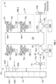
FIG. 1 shows an air distribution system of an aircraft; and -
FIG. 2 shows details of a trim module of the system shown inFIG. 1 . - A detailed description of one or more embodiments of the disclosed apparatus and method are presented herein by way of exemplification and not limitation with reference to the Figures.
- Turning to
FIG. 1 , anaircraft 100 has acabin 110 that is divided into different zones 120, e.g., first andsecond zones bay 130 of theaircraft 100 has an ECS (or system) 140. Thebay 130 is typically located below thecabin 110. - The
system 140 includes a centralizedmix manifold 150 that has at least oneinlet 160 to receive cabin air from thecabin 110. As shown by way of example, the manifold includes first andsecond inlets inlet 160 is fluidly coupled to at least oneinlet duct 165. In the example shown inFIG. 1 , in which themix manifold 150 has first andsecond inlets second inlet ducts 165A, 165B are fluidly coupled to the first andsecond inlets - At least one
recirculation fan 170 draws air from thecabin 110 to themix manifold 150 via the at least oneinlet duct 165. In the example shown inFIG. 1 , in which themix manifold 150 has first andsecond inlet ducts 165A, 165B,first andsecond recirculation fans cabin 110 into the inlets. - Cabin return air typically flows from vents located near the intersection of the fuselage and the cabin floor. The return flow moves into a cheek area of the cargo bay from which the
recirculation fans second AC packs FIG. 1 , the first andsecond AC packs second inlet ducts 165A, 165B, between the first andsecond recirculation fans mix manifold 150. Themix manifold 150 has outlets 190, e.g., first andsecond outlets mix manifold 150 are fluidly coupled with the first andsecond zones second zone ducts - To accommodate different preferences in the
zones mix manifold 150 may need further conditioning by being heated or cooled by, e.g., 10 degrees Celsius, as a non-limiting example. According to the embodiments, to provide such further conditioning, trim modules, e.g., first andsecond trim modules zone ducts trim modules trim modules trim module 210. - Turning to
FIG. 2 , details of thetrim module 210 are shown. Thetrim module 210 includes at least two heat exchangers 220, e.g., a first heat exchanger (a zone air heat exchanger) 220A and a second heat exchanger (a cabin return air heat exchanger) 220B. A thermoelectric cooler (TEC)module 230 is interposed and thermally coupled between the first andsecond heat exchangers - The
TEC module 230 is operationally coupled to thesystem 140, e.g., vialeads 230A that receive power (e.g., supply voltage) and control signals from asystem control 140A. As can be appreciated, voltage magnitude and polarity to theTEC module 230 will control its direction and magnitude of heat transfer, e.g., from thefirst heat exchanger 220A to thesecond heat exchanger 220B and vice versa. TheTEC module 230 may include a plurality of TECs, 232, 234 configured as a circuit 236. The plurality ofTECs TEC module 230, theheat exchangers - The
trim module 210 may include various conduits 240. For example, amix manifold conduit 240A is fluidly coupled between an inlet 220A1 of thefirst heat exchanger 220A and, e.g., thefirst outlet 190A (FIG. 1 ) of themix manifold 150. Azone supply conduit 240B is fluidly coupled between an outlet 220A2 of thefirst heat exchanger 220A and, e.g., thefirst zone duct 200A (FIG. 1 ) that is fluidly coupled to thefirst zone 120A. Theheat exchanger 220B is intended to draw cabin return air from the ambient environment surrounding themix manifold 150 into an inlet 220B1 using the exhaust fan 270 (discussed below). Anexhaust conduit 240E is fluidly coupled between an outlet 220B2 of thesecond heat exchanger 220B and a low-pressure TEC exhaust (overboard) manifold 255 (or exhaust manifold, for simplicity) of thesystem 140. - The
trim module 210 may include atemperature sensor 260 located in thezone supply conduit 240B. Anexhaust fan 270 may be fluidly coupled between the outlet 220B2 of thesecond heat exchanger 220B and theexhaust conduit 240E. Theexhaust fan 270 may create negative pressure that draws air frombay 130 into the inlet 220B1 of thesecond heat exchanger 220B. This enables mixing of air frombay 130 and thecabin 110 within thesecond heat exchanger 220B when conditioning air from themix manifold 150. Theexhaust fan 270 is operationally coupled to thesystem 140, e.g., via leads 230B, to receive power (e.g., supply voltage) and control signals. As can be appreciated, the supply voltage and control signals to theexhaust fan 270 may differ from the supply voltage and control signals to theTEC module 230. That is, while theTEC module 230 may be controlled to alternatively direct heat transfer between the first andsecond heat exchangers exhaust fan 270 is configured to exhaust waste air in one direction, i.e., away from thesecond heat exchanger 220B. The magnitude of the supply voltage to theexhaust fan 270 may be controlled to change the flow rate of air across thesecond heat exchanger 220B, depending on cooling or heating requirements. With theexhaust fan 270, waste air can be directed overboard from theexhaust manifold 255, or used for another purpose such as a driving a power turbine of an air cycle machine (ACM). Directing the exhaust air to theexhaust manifold 255 from thetrim module 210 avoids adding unwanted heating and cooling of theaircraft cabin 130. - The
TEC module 230 is configured to operate in a first mode or a second mode, depending on a temperature within thezone supply conduit 240B and a target temperature. In the first mode, theTEC module 230 is configured to transfer thermal energy from thefirst heat exchanger 220A to thesecond heat exchanger 220B. In the second mode, theTEC module 230 is configured to transfer thermal energy from thesecond heat exchanger 220B to thefirst heat exchanger 220A. Thus, during operation, a voltage magnitude and polarity to theTEC module 230 may be utilized to regulate the outlet temperatures of heat exchangers 220A, 220B to raise or lower the temperature of themix manifold 150 by approximately 10 degrees Celsius, as indicated. That is, thetrim module 210 provides for a heating and cooling capability of a zone 120 by varying the magnitude and polarity of voltage applied to theTEC module 230. When operating in either mode, as indicated above, the magnitude of the voltage to theexhaust fan 270 may be controlled to change the flow rate of air across thesecond heat exchanger 220B, depending on cooling or heating requirements. - With the above embodiments, a heating and cooling capability of the
TEC module 230 enables optionally running theECS 140 at a higher outlet temperature, which may translate into extra system capacity. Alternatively, a smaller ECS may be utilized. Locating thetrim module 210 at themix manifold 150 enables a low integration cost and weight for thetrim module 210 because the system wiring and theexhaust manifold 255 are confined to thebay 130. As eachtrim module 210 is configured the same, there is a reduction in recurring manufacturing costs. - In addition to the above identified benefits, the configuration enables an elimination of, e.g., diverter valves, which enables the ability to provide steady exhaust flow for other uses. Conventional pneumatic zone trim valves, trim injectors, mufflers, ducting, couplings and its associated mounting hardware is also eliminated.
- The terminology used herein is for the purpose of describing particular embodiments only and is not intended to be limiting of the present disclosure. As used herein, the singular forms "a", "an" and "the" are intended to include the plural forms as well, unless the context clearly indicates otherwise. It will be further understood that the terms "comprises" and/or "comprising," when used in this specification, specify the presence of stated features, integers, steps, operations, elements, and/or components, but do not preclude the presence or addition of one or more other features, integers, steps, operations, element components, and/or groups thereof.
- While the present disclosure has been described with reference to an exemplary embodiment or embodiments, it will be understood by those skilled in the art that various changes may be made and equivalents may be substituted for elements thereof without departing from the scope of the present disclosure. In addition, many modifications may be made to adapt a particular situation or material to the teachings of the present disclosure without departing from the essential scope thereof. Therefore, it is intended that the present disclosure not be limited to the particular embodiment disclosed as the best mode contemplated for carrying out this present disclosure, but that the present disclosure will include all embodiments falling within the scope of the claims.
Claims (15)
- A trim module (210) of an aircraft environmental control system, the trim module comprising:a first heat exchanger (220A) having an inlet and an outlet;a second heat exchanger (220B) having an inlet and an outlet; anda thermoelectric cooler, TEC, module (230) thermally coupled between the first and second heat exchangers (220A, 220B);a mix manifold conduit (240A) fluidly coupled to the inlet of the first heat exchanger;a zone supply conduit (240B) fluidly coupled to the outlet of the first heat exchanger;a cabin return conduit fluidly coupled to the inlet of the second heat exchanger;an exhaust conduit (240E) fluidly coupled to the outlet of the second heat exchanger,wherein the TEC module (230) is configured to operate in a first mode or a second mode, depending on a temperature within the zone supply conduit (240B) and a target temperature, andwherein:in the first mode, the TEC module (230) is configured to transfer thermal energy from the first heat exchanger (220A) to the second heat exchanger (220B); andin the second mode the TEC module (230) is configured to transfer thermal energy from the second heat exchanger (220B) to the first heat exchanger (220A).
- The trim module of claim 1, further comprising:
a temperature sensor (260) in the zone supply conduit (240B), wherein the TEC module (230) is configured to operate in the first mode or the second mode depending on the temperature sensed by the temperature sensor (260) and the target temperature. - The trim module of claim 2, further comprising:
an exhaust fan (270) fluidly coupled to the outlet of the second heat exchanger (220B) and the exhaust conduit (240E). - The trim module of any preceding claim, wherein:
the TEC module (230) includes a plurality of thermoelectric coolers configured as a circuit. - An environmental control system of an aircraft, comprising:a mix manifold (150) having an outlet; andthe trim module (210) of claim 1, wherein the outlet of the mix manifold (150) is fluidly coupled to the mix manifold conduit (240A) of the trim module.
- The system of claim 5, further comprising:a temperature sensor (260) in the zone supply conduit (240B),wherein the TEC module (230) is configured to operate in the first mode or the second mode depending on the temperature sensed by the temperature sensor (260) and the target temperature.
- The system of claim 6, further comprising:
an exhaust fan (270) fluidly coupled to the outlet of the second heat exchanger (220B) and the exhaust conduit. - The system of any of claims 5-7, wherein:
the TEC module (230) includes a plurality of thermoelectric coolers configured as a circuit. - The system of any of claims 5-8, further comprising:
an exhaust manifold (255) fluidly coupled to the exhaust conduit (240E) of the second heat exchanger. - The system of claim 9, wherein:the mix manifold (150) includes an inlet; andthe system includes a recirculating fan fluidly coupled to the inlet of the mix manifold (150).
- The system of claim 10, wherein:
the system includes an air conditioning pack fluidly coupled to the inlet of the mix manifold. - The system of any of claims 5-11, wherein:the mix manifold (150) includes additional outlets; andthe system includes additional trim modules fluidly coupled to respective ones of the additional outlets of the mix manifold, wherein each of the trim modules have a same configuration as each other.
- An aircraft comprising:a cabin (110) including a zone, the zone including a zone duct;a bay (130); andthe system of claim 6 disposed in the bay, wherein:a temperature sensor (260) is deposed in the zone supply conduit (240B);the zone supply conduit of the first heat exchanger is fluidly coupled to the zone duct of the zone; andan exhaust fan is fluidly coupled to the outlet of the second heat exchanger and the exhaust conduit.
- The aircraft of claim 13, wherein:
the TEC module (230) includes a plurality of thermoelectric coolers configured as a circuit. - The aircraft of claim 14, wherein:
the plurality of thermoelectric coolers are electrically coupled in series or parallel; or wherein:
the plurality of thermoelectric coolers are thermally coupled in series or parallel.
Applications Claiming Priority (1)
| Application Number | Priority Date | Filing Date | Title |
|---|---|---|---|
| US17/732,671 US12071247B2 (en) | 2022-04-29 | 2022-04-29 | Trim module with thermoelectric cooler |
Publications (2)
| Publication Number | Publication Date |
|---|---|
| EP4269246A1 true EP4269246A1 (en) | 2023-11-01 |
| EP4269246B1 EP4269246B1 (en) | 2025-03-19 |
Family
ID=86142957
Family Applications (1)
| Application Number | Title | Priority Date | Filing Date |
|---|---|---|---|
| EP23169283.1A Active EP4269246B1 (en) | 2022-04-29 | 2023-04-21 | Trim module with thermoelectric cooler |
Country Status (2)
| Country | Link |
|---|---|
| US (1) | US12071247B2 (en) |
| EP (1) | EP4269246B1 (en) |
Families Citing this family (1)
| Publication number | Priority date | Publication date | Assignee | Title |
|---|---|---|---|---|
| US11999492B2 (en) | 2022-05-19 | 2024-06-04 | Textron Innovations Inc. | Electric temperature control system for unpressurized aircraft |
Citations (6)
| Publication number | Priority date | Publication date | Assignee | Title |
|---|---|---|---|---|
| US5584183A (en) * | 1994-02-18 | 1996-12-17 | Solid State Cooling Systems | Thermoelectric heat exchanger |
| EP0730720B1 (en) * | 1993-11-22 | 2000-07-05 | Amerigon, Inc. | Variable temperature seat climate control system |
| DE102010015741A1 (en) * | 2009-04-24 | 2011-08-18 | GM Global Technology Operations LLC, ( n. d. Ges. d. Staates Delaware ), Mich. | Thermoelectric climate control |
| EP3330181A1 (en) * | 2016-11-30 | 2018-06-06 | Hamilton Sundstrand Corporation | Air distribution manifold with integral multizone thermoelectric tec trim system |
| EP3333078A1 (en) * | 2016-12-08 | 2018-06-13 | Hamilton Sundstrand Corporation | Air distribution system with recirculating zone trim tec |
| US20210318036A1 (en) * | 2020-04-13 | 2021-10-14 | The Boeing Company | Air distribution system and method including a thermocouple device |
Family Cites Families (7)
| Publication number | Priority date | Publication date | Assignee | Title |
|---|---|---|---|---|
| DE3333078A1 (en) | 1983-09-14 | 1985-03-21 | Atis Assmann GmbH, 6380 Bad Homburg | VIDEO SURVEILLANCE |
| US6530231B1 (en) * | 2000-09-22 | 2003-03-11 | Te Technology, Inc. | Thermoelectric assembly sealing member and thermoelectric assembly incorporating same |
| DE102006005037B4 (en) | 2006-02-03 | 2012-03-29 | Airbus Operations Gmbh | Air conditioning arrangement for an aircraft with several individually temperature-controllable climates |
| KR101343736B1 (en) * | 2011-11-22 | 2013-12-19 | 갑을오토텍(주) | Condensing water removing appatarus of airconditioner |
| US9783309B2 (en) * | 2013-07-16 | 2017-10-10 | The Boeing Company | Methods and device for mixing airflows in environmental control systems |
| WO2018169178A1 (en) * | 2017-03-15 | 2018-09-20 | 엘지전자 주식회사 | Refrigerator |
| US20200377216A1 (en) | 2019-05-31 | 2020-12-03 | Hamilton Sundstrand Corporation | Aircraft cabin air thermodynamic control |
-
2022
- 2022-04-29 US US17/732,671 patent/US12071247B2/en active Active
-
2023
- 2023-04-21 EP EP23169283.1A patent/EP4269246B1/en active Active
Patent Citations (6)
| Publication number | Priority date | Publication date | Assignee | Title |
|---|---|---|---|---|
| EP0730720B1 (en) * | 1993-11-22 | 2000-07-05 | Amerigon, Inc. | Variable temperature seat climate control system |
| US5584183A (en) * | 1994-02-18 | 1996-12-17 | Solid State Cooling Systems | Thermoelectric heat exchanger |
| DE102010015741A1 (en) * | 2009-04-24 | 2011-08-18 | GM Global Technology Operations LLC, ( n. d. Ges. d. Staates Delaware ), Mich. | Thermoelectric climate control |
| EP3330181A1 (en) * | 2016-11-30 | 2018-06-06 | Hamilton Sundstrand Corporation | Air distribution manifold with integral multizone thermoelectric tec trim system |
| EP3333078A1 (en) * | 2016-12-08 | 2018-06-13 | Hamilton Sundstrand Corporation | Air distribution system with recirculating zone trim tec |
| US20210318036A1 (en) * | 2020-04-13 | 2021-10-14 | The Boeing Company | Air distribution system and method including a thermocouple device |
Also Published As
| Publication number | Publication date |
|---|---|
| US20230348068A1 (en) | 2023-11-02 |
| EP4269246B1 (en) | 2025-03-19 |
| US12071247B2 (en) | 2024-08-27 |
Similar Documents
| Publication | Publication Date | Title |
|---|---|---|
| US10752365B2 (en) | Method and device for thermal control of a plurality of cabins of a vehicle | |
| CN103079956B (en) | Aircraft air-conditioning system including the kind of refrigeration cycle separated | |
| EP1979232B1 (en) | Air conditioning arrangement for an aircraft with a plurality of climate zones that may be individually temperature-controlled | |
| US4482114A (en) | Integrated thermal anti-icing and environmental control system | |
| US9561856B2 (en) | Heat exchanger, cooling system and method for operating a heat exchanger and a cooling system | |
| US10202197B2 (en) | Aircraft air conditioning system with an electrically driven ambient air compressor and method for operating such an aircraft air conditioning system | |
| EP3733518B1 (en) | Reverse bootstrap air cycle machine | |
| EP3333078B1 (en) | Air distribution system with recirculating zone trim tec | |
| US9469407B2 (en) | Fluid temperature control installation for rotorcraft, associating a system for cooling a power plant with a system for heating a cabin | |
| EP3415433B1 (en) | High efficiency electrically driven environmental control system | |
| EP3085623B1 (en) | Modular environmental air conditioning system | |
| EP3590839B1 (en) | Pressure optimized sourcing of cabin pressurization and component air cooling | |
| EP3241757A1 (en) | Fuel tank inerting systems for aircraft | |
| EP4269246B1 (en) | Trim module with thermoelectric cooler | |
| EP3330181B1 (en) | Air distribution manifold with integral multizone thermoelectric tec trim system | |
| GB2166542A (en) | Air conditioning systems for aircraft cabins | |
| US20040149427A1 (en) | Aircraft ground support air conditioning unit with cooling air flow control doors | |
| US11046441B2 (en) | Adaptive plate-fin heat exchanger | |
| US20240308669A1 (en) | Energy recovery and thermal control utilizing heat pump | |
| EP4606707A1 (en) | Environmental control systems for an aircraft having a vapor compression system with a flash liquid expander turbine | |
| US20240300549A1 (en) | Hyperloop environmental control system | |
| CN111516882B (en) | Heating and ventilation systems for aircraft cabins |
Legal Events
| Date | Code | Title | Description |
|---|---|---|---|
| PUAI | Public reference made under article 153(3) epc to a published international application that has entered the european phase |
Free format text: ORIGINAL CODE: 0009012 |
|
| STAA | Information on the status of an ep patent application or granted ep patent |
Free format text: STATUS: THE APPLICATION HAS BEEN PUBLISHED |
|
| AK | Designated contracting states |
Kind code of ref document: A1 Designated state(s): AL AT BE BG CH CY CZ DE DK EE ES FI FR GB GR HR HU IE IS IT LI LT LU LV MC ME MK MT NL NO PL PT RO RS SE SI SK SM TR |
|
| STAA | Information on the status of an ep patent application or granted ep patent |
Free format text: STATUS: REQUEST FOR EXAMINATION WAS MADE |
|
| 17P | Request for examination filed |
Effective date: 20240424 |
|
| RBV | Designated contracting states (corrected) |
Designated state(s): AL AT BE BG CH CY CZ DE DK EE ES FI FR GB GR HR HU IE IS IT LI LT LU LV MC ME MK MT NL NO PL PT RO RS SE SI SK SM TR |
|
| GRAP | Despatch of communication of intention to grant a patent |
Free format text: ORIGINAL CODE: EPIDOSNIGR1 |
|
| STAA | Information on the status of an ep patent application or granted ep patent |
Free format text: STATUS: GRANT OF PATENT IS INTENDED |
|
| INTG | Intention to grant announced |
Effective date: 20241024 |
|
| GRAS | Grant fee paid |
Free format text: ORIGINAL CODE: EPIDOSNIGR3 |
|
| GRAA | (expected) grant |
Free format text: ORIGINAL CODE: 0009210 |
|
| STAA | Information on the status of an ep patent application or granted ep patent |
Free format text: STATUS: THE PATENT HAS BEEN GRANTED |
|
| AK | Designated contracting states |
Kind code of ref document: B1 Designated state(s): AL AT BE BG CH CY CZ DE DK EE ES FI FR GB GR HR HU IE IS IT LI LT LU LV MC ME MK MT NL NO PL PT RO RS SE SI SK SM TR |
|
| REG | Reference to a national code |
Ref country code: GB Ref legal event code: FG4D |
|
| REG | Reference to a national code |
Ref country code: CH Ref legal event code: EP |
|
| REG | Reference to a national code |
Ref country code: DE Ref legal event code: R096 Ref document number: 602023002439 Country of ref document: DE |
|
| REG | Reference to a national code |
Ref country code: IE Ref legal event code: FG4D |
|
| PG25 | Lapsed in a contracting state [announced via postgrant information from national office to epo] |
Ref country code: RS Free format text: LAPSE BECAUSE OF FAILURE TO SUBMIT A TRANSLATION OF THE DESCRIPTION OR TO PAY THE FEE WITHIN THE PRESCRIBED TIME-LIMIT Effective date: 20250619 |
|
| PG25 | Lapsed in a contracting state [announced via postgrant information from national office to epo] |
Ref country code: FI Free format text: LAPSE BECAUSE OF FAILURE TO SUBMIT A TRANSLATION OF THE DESCRIPTION OR TO PAY THE FEE WITHIN THE PRESCRIBED TIME-LIMIT Effective date: 20250319 |
|
| PGFP | Annual fee paid to national office [announced via postgrant information from national office to epo] |
Ref country code: DE Payment date: 20250319 Year of fee payment: 3 |
|
| REG | Reference to a national code |
Ref country code: LT Ref legal event code: MG9D |
|
| PG25 | Lapsed in a contracting state [announced via postgrant information from national office to epo] |
Ref country code: NO Free format text: LAPSE BECAUSE OF FAILURE TO SUBMIT A TRANSLATION OF THE DESCRIPTION OR TO PAY THE FEE WITHIN THE PRESCRIBED TIME-LIMIT Effective date: 20250619 |
|
| PG25 | Lapsed in a contracting state [announced via postgrant information from national office to epo] |
Ref country code: HR Free format text: LAPSE BECAUSE OF FAILURE TO SUBMIT A TRANSLATION OF THE DESCRIPTION OR TO PAY THE FEE WITHIN THE PRESCRIBED TIME-LIMIT Effective date: 20250319 |
|
| PG25 | Lapsed in a contracting state [announced via postgrant information from national office to epo] |
Ref country code: LV Free format text: LAPSE BECAUSE OF FAILURE TO SUBMIT A TRANSLATION OF THE DESCRIPTION OR TO PAY THE FEE WITHIN THE PRESCRIBED TIME-LIMIT Effective date: 20250319 |
|
| PG25 | Lapsed in a contracting state [announced via postgrant information from national office to epo] |
Ref country code: GR Free format text: LAPSE BECAUSE OF FAILURE TO SUBMIT A TRANSLATION OF THE DESCRIPTION OR TO PAY THE FEE WITHIN THE PRESCRIBED TIME-LIMIT Effective date: 20250620 Ref country code: BG Free format text: LAPSE BECAUSE OF FAILURE TO SUBMIT A TRANSLATION OF THE DESCRIPTION OR TO PAY THE FEE WITHIN THE PRESCRIBED TIME-LIMIT Effective date: 20250319 |
|
| REG | Reference to a national code |
Ref country code: NL Ref legal event code: MP Effective date: 20250319 |
|
| REG | Reference to a national code |
Ref country code: AT Ref legal event code: MK05 Ref document number: 1776783 Country of ref document: AT Kind code of ref document: T Effective date: 20250319 |
|
| PG25 | Lapsed in a contracting state [announced via postgrant information from national office to epo] |
Ref country code: NL Free format text: LAPSE BECAUSE OF FAILURE TO SUBMIT A TRANSLATION OF THE DESCRIPTION OR TO PAY THE FEE WITHIN THE PRESCRIBED TIME-LIMIT Effective date: 20250319 |
|
| PG25 | Lapsed in a contracting state [announced via postgrant information from national office to epo] |
Ref country code: SE Free format text: LAPSE BECAUSE OF FAILURE TO SUBMIT A TRANSLATION OF THE DESCRIPTION OR TO PAY THE FEE WITHIN THE PRESCRIBED TIME-LIMIT Effective date: 20250319 |
|
| PG25 | Lapsed in a contracting state [announced via postgrant information from national office to epo] |
Ref country code: SM Free format text: LAPSE BECAUSE OF FAILURE TO SUBMIT A TRANSLATION OF THE DESCRIPTION OR TO PAY THE FEE WITHIN THE PRESCRIBED TIME-LIMIT Effective date: 20250319 |
|
| PG25 | Lapsed in a contracting state [announced via postgrant information from national office to epo] |
Ref country code: ES Free format text: LAPSE BECAUSE OF FAILURE TO SUBMIT A TRANSLATION OF THE DESCRIPTION OR TO PAY THE FEE WITHIN THE PRESCRIBED TIME-LIMIT Effective date: 20250319 Ref country code: PT Free format text: LAPSE BECAUSE OF FAILURE TO SUBMIT A TRANSLATION OF THE DESCRIPTION OR TO PAY THE FEE WITHIN THE PRESCRIBED TIME-LIMIT Effective date: 20250721 |
|
| PG25 | Lapsed in a contracting state [announced via postgrant information from national office to epo] |
Ref country code: PL Free format text: LAPSE BECAUSE OF FAILURE TO SUBMIT A TRANSLATION OF THE DESCRIPTION OR TO PAY THE FEE WITHIN THE PRESCRIBED TIME-LIMIT Effective date: 20250319 Ref country code: IT Free format text: LAPSE BECAUSE OF FAILURE TO SUBMIT A TRANSLATION OF THE DESCRIPTION OR TO PAY THE FEE WITHIN THE PRESCRIBED TIME-LIMIT Effective date: 20250319 |
|
| PG25 | Lapsed in a contracting state [announced via postgrant information from national office to epo] |
Ref country code: AT Free format text: LAPSE BECAUSE OF FAILURE TO SUBMIT A TRANSLATION OF THE DESCRIPTION OR TO PAY THE FEE WITHIN THE PRESCRIBED TIME-LIMIT Effective date: 20250319 |
|
| PG25 | Lapsed in a contracting state [announced via postgrant information from national office to epo] |
Ref country code: EE Free format text: LAPSE BECAUSE OF FAILURE TO SUBMIT A TRANSLATION OF THE DESCRIPTION OR TO PAY THE FEE WITHIN THE PRESCRIBED TIME-LIMIT Effective date: 20250319 Ref country code: CZ Free format text: LAPSE BECAUSE OF FAILURE TO SUBMIT A TRANSLATION OF THE DESCRIPTION OR TO PAY THE FEE WITHIN THE PRESCRIBED TIME-LIMIT Effective date: 20250319 |
|
| PG25 | Lapsed in a contracting state [announced via postgrant information from national office to epo] |
Ref country code: RO Free format text: LAPSE BECAUSE OF FAILURE TO SUBMIT A TRANSLATION OF THE DESCRIPTION OR TO PAY THE FEE WITHIN THE PRESCRIBED TIME-LIMIT Effective date: 20250319 |
|
| PG25 | Lapsed in a contracting state [announced via postgrant information from national office to epo] |
Ref country code: SK Free format text: LAPSE BECAUSE OF FAILURE TO SUBMIT A TRANSLATION OF THE DESCRIPTION OR TO PAY THE FEE WITHIN THE PRESCRIBED TIME-LIMIT Effective date: 20250319 |
|
| PG25 | Lapsed in a contracting state [announced via postgrant information from national office to epo] |
Ref country code: IS Free format text: LAPSE BECAUSE OF FAILURE TO SUBMIT A TRANSLATION OF THE DESCRIPTION OR TO PAY THE FEE WITHIN THE PRESCRIBED TIME-LIMIT Effective date: 20250719 |
|
| PG25 | Lapsed in a contracting state [announced via postgrant information from national office to epo] |
Ref country code: LU Free format text: LAPSE BECAUSE OF NON-PAYMENT OF DUE FEES Effective date: 20250421 |
|
| PG25 | Lapsed in a contracting state [announced via postgrant information from national office to epo] |
Ref country code: MC Free format text: LAPSE BECAUSE OF FAILURE TO SUBMIT A TRANSLATION OF THE DESCRIPTION OR TO PAY THE FEE WITHIN THE PRESCRIBED TIME-LIMIT Effective date: 20250319 |
|
| REG | Reference to a national code |
Ref country code: DE Ref legal event code: R097 Ref document number: 602023002439 Country of ref document: DE |
|
| REG | Reference to a national code |
Ref country code: BE Ref legal event code: MM Effective date: 20250430 |
|
| PG25 | Lapsed in a contracting state [announced via postgrant information from national office to epo] |
Ref country code: DK Free format text: LAPSE BECAUSE OF FAILURE TO SUBMIT A TRANSLATION OF THE DESCRIPTION OR TO PAY THE FEE WITHIN THE PRESCRIBED TIME-LIMIT Effective date: 20250319 |
|
| PG25 | Lapsed in a contracting state [announced via postgrant information from national office to epo] |
Ref country code: BE Free format text: LAPSE BECAUSE OF NON-PAYMENT OF DUE FEES Effective date: 20250430 |
|
| PLBE | No opposition filed within time limit |
Free format text: ORIGINAL CODE: 0009261 |
|
| STAA | Information on the status of an ep patent application or granted ep patent |
Free format text: STATUS: NO OPPOSITION FILED WITHIN TIME LIMIT |
|
| REG | Reference to a national code |
Ref country code: CH Ref legal event code: L10 Free format text: ST27 STATUS EVENT CODE: U-0-0-L10-L00 (AS PROVIDED BY THE NATIONAL OFFICE) Effective date: 20260128 |
|
| 26N | No opposition filed |
Effective date: 20251222 |
|
| PG25 | Lapsed in a contracting state [announced via postgrant information from national office to epo] |
Ref country code: IE Free format text: LAPSE BECAUSE OF NON-PAYMENT OF DUE FEES Effective date: 20250421 |
|
| PGFP | Annual fee paid to national office [announced via postgrant information from national office to epo] |
Ref country code: FR Payment date: 20260320 Year of fee payment: 4 |