EP4269156A1 - Adjusting and/or customising a user interface of a vehicle - Google Patents
Adjusting and/or customising a user interface of a vehicle Download PDFInfo
- Publication number
- EP4269156A1 EP4269156A1 EP22170891.0A EP22170891A EP4269156A1 EP 4269156 A1 EP4269156 A1 EP 4269156A1 EP 22170891 A EP22170891 A EP 22170891A EP 4269156 A1 EP4269156 A1 EP 4269156A1
- Authority
- EP
- European Patent Office
- Prior art keywords
- vehicle
- user interface
- data
- unit
- providing
- Prior art date
- Legal status (The legal status is an assumption and is not a legal conclusion. Google has not performed a legal analysis and makes no representation as to the accuracy of the status listed.)
- Granted
Links
Images



Classifications
-
- B—PERFORMING OPERATIONS; TRANSPORTING
- B60—VEHICLES IN GENERAL
- B60K—ARRANGEMENT OR MOUNTING OF PROPULSION UNITS OR OF TRANSMISSIONS IN VEHICLES; ARRANGEMENT OR MOUNTING OF PLURAL DIVERSE PRIME-MOVERS IN VEHICLES; AUXILIARY DRIVES FOR VEHICLES; INSTRUMENTATION OR DASHBOARDS FOR VEHICLES; ARRANGEMENTS IN CONNECTION WITH COOLING, AIR INTAKE, GAS EXHAUST OR FUEL SUPPLY OF PROPULSION UNITS IN VEHICLES
- B60K35/00—Instruments specially adapted for vehicles; Arrangement of instruments in or on vehicles
- B60K35/10—Input arrangements, i.e. from user to vehicle, associated with vehicle functions or specially adapted therefor
-
- B—PERFORMING OPERATIONS; TRANSPORTING
- B60—VEHICLES IN GENERAL
- B60K—ARRANGEMENT OR MOUNTING OF PROPULSION UNITS OR OF TRANSMISSIONS IN VEHICLES; ARRANGEMENT OR MOUNTING OF PLURAL DIVERSE PRIME-MOVERS IN VEHICLES; AUXILIARY DRIVES FOR VEHICLES; INSTRUMENTATION OR DASHBOARDS FOR VEHICLES; ARRANGEMENTS IN CONNECTION WITH COOLING, AIR INTAKE, GAS EXHAUST OR FUEL SUPPLY OF PROPULSION UNITS IN VEHICLES
- B60K2360/00—Indexing scheme associated with groups B60K35/00 or B60K37/00 relating to details of instruments or dashboards
- B60K2360/11—Instrument graphical user interfaces or menu aspects
- B60K2360/111—Instrument graphical user interfaces or menu aspects for controlling multiple devices
-
- B—PERFORMING OPERATIONS; TRANSPORTING
- B60—VEHICLES IN GENERAL
- B60K—ARRANGEMENT OR MOUNTING OF PROPULSION UNITS OR OF TRANSMISSIONS IN VEHICLES; ARRANGEMENT OR MOUNTING OF PLURAL DIVERSE PRIME-MOVERS IN VEHICLES; AUXILIARY DRIVES FOR VEHICLES; INSTRUMENTATION OR DASHBOARDS FOR VEHICLES; ARRANGEMENTS IN CONNECTION WITH COOLING, AIR INTAKE, GAS EXHAUST OR FUEL SUPPLY OF PROPULSION UNITS IN VEHICLES
- B60K2360/00—Indexing scheme associated with groups B60K35/00 or B60K37/00 relating to details of instruments or dashboards
- B60K2360/122—Instrument input devices with reconfigurable control functions, e.g. reconfigurable menus
-
- G—PHYSICS
- G06—COMPUTING OR CALCULATING; COUNTING
- G06F—ELECTRIC DIGITAL DATA PROCESSING
- G06F3/00—Input arrangements for transferring data to be processed into a form capable of being handled by the computer; Output arrangements for transferring data from processing unit to output unit, e.g. interface arrangements
- G06F3/14—Digital output to display device ; Cooperation and interconnection of the display device with other functional units
- G06F3/147—Digital output to display device ; Cooperation and interconnection of the display device with other functional units using display panels
-
- G—PHYSICS
- G09—EDUCATION; CRYPTOGRAPHY; DISPLAY; ADVERTISING; SEALS
- G09G—ARRANGEMENTS OR CIRCUITS FOR CONTROL OF INDICATING DEVICES USING STATIC MEANS TO PRESENT VARIABLE INFORMATION
- G09G2354/00—Aspects of interface with display user
-
- G—PHYSICS
- G09—EDUCATION; CRYPTOGRAPHY; DISPLAY; ADVERTISING; SEALS
- G09G—ARRANGEMENTS OR CIRCUITS FOR CONTROL OF INDICATING DEVICES USING STATIC MEANS TO PRESENT VARIABLE INFORMATION
- G09G2380/00—Specific applications
- G09G2380/10—Automotive applications
Definitions
- the present disclosure relates to a computer-implemented method for adjusting and/or customising a user interface of a vehicle, a system for adjusting and/or customising a user interface of the vehicle and a corresponding computer program element.
- user interface systems e.g. graphical user interface systems
- displays in vehicles which, for example, provide a driver with information about the vehicle and/or the state of the vehicle, these user interface systems being created for a particular application and/or for a particular vehicle.
- the user interface systems are individually tailored to the respective application with the respective functions, so that a reuse of certain functions, which are also used in other user interface systems, is generally not possible, so that an additional effort arises in the development of different user interface systems.
- adjustments and/or modifications of a function of a user interface system are also only possible with the revision of the entire user interface system, just as updating a function of a user interface system of a vehicle may only be performed as an overall update of the user interface system.
- a user interface system may negatively affect the driving safety of a vehicle and/or trigger failures in the function of the vehicle.
- responding to user experience in terms of adjusting and/or customizing a feature is also only possible by updating the entire user interface systems.
- a computer-implemented method for adjusting and/or customising a user interface of a vehicle comprising:
- the computer-implemented method may be a prototyping platform that supports complex, rapid ideation and/or implementation of user interfaces in terms of human-centric design for a road-legal test fleet.
- vehicle functions may be read and written from vehicle signals in real time to meet the specific requirements of user interfaces, e.g., different prototypes of a user interface.
- a prototype of a user interface for driving a vehicle, testing a vehicle and/or for presentation purposes for meetings may be created.
- the present disclosure is not limited to such prototyping platform.
- the prototyping platform may comprise a complete tech stack or technical package that may be modular, with each module operating independently and interchangeable to adapt to the specific needs of a prototype.
- the prototyping platform may provide a common and reusable toolset for prototyping user experience in prototypes for user interfaces, which may improve the process of creating user interfaces for vehicle regarding the needed time and resources, by having to reimplement core functionality needed for each prototype of a user interface.
- the prototyping platform may provide a common set of user-friendly tools, both in terms of hardware and software implementation, to may reduce the effort required to explore new technologies and ideas that may be tested in a vehicle, to be able to reduce development costs and improve the driver experience of a vehicle.
- the computer-implemented method may comprises: providing, by the vehicle, vehicle data, which may comprise information about vehicle parameters and providing, by the computing unit, user interface control data for the at least one user interface, which may be further based on the provided vehicle data.
- the vehicle data may be provided, for example, by a control unit of the vehicle, with the user interface accessing and/or displaying the vehicle data.
- the control data for the user interface may be provided separately to the vehicle, for example, by a system.
- the user interface control data may comprises information about a selection of vehicle parameters for displaying by the at least one user interface.
- the vehicle parameters displayed may vary depending on the application, vehicle type, user interface type, prototype of a user interface, etc.
- the vehicle data may comprises a vehicle speed of the vehicle, a vehicle gear level of the vehicle, a vehicle fuel range of the vehicle, a GPS location of the vehicle and/or further vehicle parameters.
- other data e.g., weather data, may also be used/displayed.
- Additional signals or data used and/or generated in a vehicle may also be displayed.
- the vehicle data may be provided by the vehicle, e.g. by vehicle bus systems, preferably by a Flexray bus system, Controller Area Network bus system, CAN, Local Interconnect Network bus system, LIN, and/or automotive Ethernet bus system.
- vehicle bus systems preferably by a Flexray bus system, Controller Area Network bus system, CAN, Local Interconnect Network bus system, LIN, and/or automotive Ethernet bus system.
- vehicle data of various vehicle buses used in a vehicle may be provided.
- the user interface may be configured to process web technology, in particular HTML data, CSS data and/or JavaScript data.
- the user interface may comprise one or more elements that use web technologies for enabling fast iteration, deployment and reuse.
- making a new user interface, e.g. a prototype user interface, for a vehicle may become as simple as making a website.
- the user interface or prototype user interfaces of vehicles for driving, testing, or presenting may be in the state of being displayed as a web page as in the world wide web or documents and data in a web browser or internet browser in general.
- request data e.g. a request of a driver
- the user interface control data may then be further based on the request data
- the request data which may be a vehicle parameter and/or user interface control data may be distinct from a driver's requirement for the vehicle.
- the user interface may be an augmented reality user interface of the vehicle, a head-up display interface of the vehicle and/or a cockpit display interface of the vehicle.
- this prototyping platform may provide flexibility to use existing vehicle features, integrate new technologies, and perform user testing in road environments of a vehicle.
- user interface prototypes developed with this platform may also be used in AR/VR environments or as showcase content during design reviews.
- the vehicle may be provided by means of a vehicle software model.
- the method may be performed as virtual reality model based on simulated vehicle data.
- real-time may be defined in a timeframe of 10 milliseconds [ms] to 1000 [ms], preferably between 50 [ms] and 300 [ms] and most preferably about 100 [ms].
- a further aspect of the present discourse relates to a system for adjusting and/or customising a user interface of a vehicle comprising:
- system may comprise:
- the gateway unit may be an interface to read and/or write vehicle buses.
- the message broker unit may be a central hub to pass along messages of the system, in particular the control module, on request, for example, as pub/sub architecture. Therefore, the message broker unit decouples the units of the system, in particular, the control module.
- the custom logic unit may be a middleware to enable stream signal processing.
- middleware refers to application-neutral programs that mediate between applications in such a way that the complexity of these applications and their infrastructure are hidden.
- the remote control unit may be an interface for subscribing and publishing both vehicle data and user interface data.
- the HMI unit may be user-facing elements that affords communication and interaction, e.g. output/input for the driver of the vehicle.
- a further aspect of the present discourse relates to a vehicle and/or computing unit configured to perform the herein disclosed method.
- a further aspect of the present discourse relates to a computer program element with instructions, which, when executed on a computing device of a computing environment, is configured to carry out the steps of the disclosed method in the disclosed system.
- Figure 1 shows a schematic diagram of a process of the disclosed method, whereby the method comprises the steps of providing, by the vehicle, user interface data 10 of the vehicle to a separate computing unit, comprising at least information about the visualization parameters of at least one user interface. Further, a providing, by the computing unit, user interface control data 20 for the at least one user interface based on the provided user interface data. Further, a transmitting the user interface control data 30 to the vehicle. Further, an adjusting and/or a customising, by the vehicle, the at least one user interface 40 based on the user interface control data in real time.
- Figure 2 shows a schematic illustration of an example of a system for adjusting and/or customising a user interface of a vehicle 100 comprising different units.
- a first providing unit 101 of the vehicle configured to provide user interface data of the vehicle to a separate computing unit 120, comprising at least information about the visualization parameters of at least one user interface, e.g., a cockpit user interface of the vehicle 100.
- the user interface data of the vehicle may be provided to the computing unit 120 by any wireless communication method, e.g. any wireless communication technology, like a mobile communication, a Bluetooth communication, etc.
- the user interface data of the vehicle 100 may be provided to the computing unit 120 by any wire based communication standard, for example, a smart grid communication for electric vehicles during charging the electric vehicle or by means of a wired control device.
- a second providing unit 121 of the computing unit 120 configured to provide user interface control data for the at least one user interface based on the provided user interface data.
- a transmitting unit 122 configured to transmit the user interface control data to the vehicle 100.
- the above-mentioned communication methods may be applied/used.
- An adjusting and/or customising unit 102 of the vehicle 100 configured to adjust and/or customise the at least one user interface based on the user interface control data in real time.
- a gateway unit 103 a message broker unit 104, a custom logic unit 105, a remote control unit 106 and a HMI unit 107 are provided in the shown example.
- the HMI unit 107 is configured to display the user interface.
- Figure 3 shows a schematic illustration of an example architecture of a method and a system 110, comprising a vehicle 100, a (prototype) database and/or a software (prototype) tool 110.1 of the system 110, a gateway unit 103, a message broker unit 104, a custom logic unit 105, a remote control unit 106 and a HMI unit 107.
- the (prototype) database and/or software (prototype) tool 110.1 may comprise additional devices that may be included in the user interface setup and provide, for example, a configuration of buttons and/or new buttons for a steering wheel of a vehicle.
- the (prototype) database and/or software (prototype) tool 110.1 may simulate an environment for augmented reality and/or virtual reality.
- the vehicle 100 and the database 110.1 aggregated as a first stage 111 and the gateway unit 103, the message broker unit 104, the custom logic unit 105, the remote control unit 106 and the HMI unit 107 aggregated as a second stage 112.
- the first stage 111 and the second stage 112 are configured to communicate in a bidirectional way with each other.
- the first stage 111 and/or the second stage 112 may be further configured to communication with further units/entities, e.g. server systems.
- the first stage 111 provides data to the second stage 112 and the second stage 112 process the provided data.
- data is received by the vehicle 100, whereby, the custom logic unit 105 receives a list of signals of the vehicle 100 requested by the remote control unit 106 and the HMI unit 107.
- the gateway unit 103 reads the signals from the vehicle busses, e.g. Flexray, CAN, LIN and/or automotive Ethernet, in real time. Whereby, the gateway unit 103 decodes the requested signals of the vehicle to human readable values and passes them to the custom logic unit 105.
- the custom logic unit 105 allows combining, process or simply passing through the incoming data, as needed. Further, the custom logic unit 105 publishes the data to the message broker unit 104 as requested.
- the HMI unit 107 displays the received data, for example, vehicle speed, gear, fuel range and/or GPS of the vehicle 100.
- data is received by the database 110.1, whereby the database 110.1 publish the data to the message broker unit 104.
- the custom logic unit 105 combines and/or process the data of the database 110.1, as needed. Further, the custom logic unit 105 publishes the data to the message broker unit 104.
- the HMI unit 107 displays the received data for example turn-by-turn indications and/or steering wheel button inputs.
- data is received by the remote control unit 106, whereby the remote control unit 106 publishes the data to the message broker unit 104.
- the custom logic unit 105 combines and/or processes the data of the remote control unit 106, as needed. Further, the custom logic unit 105 publishes the data to the message broker unit 104.
- the HMI unit 107 displays the received data, for example, notifications and/or user interface context changes.
- data is send to the vehicle 100, whereby received data being sent via the remote control unit 106 and/or database 110.1 from the custom logic unit 105 via the message broker unit 104 to the vehicle 100.
- a set of steering wheel buttons may be send to the vehicle, which should be pressed to activate a vehicle function.
- the request is received by the custom logic unit 105.
- the custom logic unit 105 translates the request to a vehicle readable format: a set of vehicle signals that will activate the vehicle function. This set of signals are injected into the vehicle's busses by the gateway unit 103.
- Figure 4 shows a schematic illustration of a first example of a user interface on a HMI unit 107 of a vehicle.
- the user interface comprise at least a first field 201, a second field 202, third field 203, fourth field 204 and a fifth field 205.
- the user interface shows a first field view of a speed of the vehicle comprising the actual speed and the unit of the speed.
- the user interface shows a first field view of a used gear of a transmission of the vehicle, comprising the possible gears of the transmission and a highlighting of the used gear.
- the user interface shows a first field view of navigation instructions for reaching a desired destination that comprises a distance for the next change of direction, a direction for the change of direction, and a location that will be reached next.
- the user interface shows a remaining range of the vehicle, for example, based on the remaining fuel and/or charge of a battery of the vehicle.
- the user interface shows a map of the location of the vehicle with an indication of a driving direction of the vehicle.
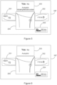
- Figure 5 shows a schematic illustration of a second example of a user interface on a HMI unit 107 similar to figure 4 .
- the user interface shows a second field view of autopilot information for the usage of the vehicle.
- the steering wheel buttons are configured or reconfigured to activate an autopilot mode of the vehicle. It is further displayed in the third field 203 that a driver may activate the autopilot by holding the steering wheel buttons, i.e. the HMI unit 107 displays a notification on the availability of a specific vehicle function, here an autopilot function of the vehicle.
- Figure 6 shows a schematic illustration of a third example of a user interface on a HMI unit 107 similar to figure 4 .
- the user interface shows an autopilot information, here that the autopilot mode of the vehicle is actually used.
- Figure 7 shows a schematic illustration of a fourth example of a user interface on a HMI unit 107 similar to figure 4 .
- the user interface shows a second field view of a speed of the vehicle comprising the speed.
- the autopilot mode is activated.
- the user interface in figure 7 does not comprise a fourth field 204.
Landscapes
- Engineering & Computer Science (AREA)
- Chemical & Material Sciences (AREA)
- Combustion & Propulsion (AREA)
- Transportation (AREA)
- Mechanical Engineering (AREA)
- User Interface Of Digital Computer (AREA)
Abstract
- providing, by the vehicle, user interface data (10) of the vehicle to a separate computing unit, comprising at least information about the visualization parameters of at least one user interface;
- providing, by the computing unit, user interface control data (20) for the at least one user interface based on the provided user interface data;
- transmitting the user interface control data (30) to the vehicle; and
- adjusting and/or customising, by the vehicle, the at least one user interface (40) based on the user interface control data in real time.
Description
- The present disclosure relates to a computer-implemented method for adjusting and/or customising a user interface of a vehicle, a system for adjusting and/or customising a user interface of the vehicle and a corresponding computer program element.
- In the prior art, user interface systems, e.g. graphical user interface systems, are known for displays in vehicles, which, for example, provide a driver with information about the vehicle and/or the state of the vehicle, these user interface systems being created for a particular application and/or for a particular vehicle. Thereby, the user interface systems are individually tailored to the respective application with the respective functions, so that a reuse of certain functions, which are also used in other user interface systems, is generally not possible, so that an additional effort arises in the development of different user interface systems. Furthermore, adjustments and/or modifications of a function of a user interface system are also only possible with the revision of the entire user interface system, just as updating a function of a user interface system of a vehicle may only be performed as an overall update of the user interface system. Moreover, a user interface system may negatively affect the driving safety of a vehicle and/or trigger failures in the function of the vehicle. In addition, responding to user experience in terms of adjusting and/or customizing a feature is also only possible by updating the entire user interface systems.
- In view of this, it is found that a further need exists to provide an improved method for adjusting and/or customising a user interface of a vehicle.
- In the view of the above, it is an object of the present disclosure to provide an improved method for adjusting and/or customising a user interface of a vehicle.
- These and other objects, which become apparent upon reading the following description, are solved by the subject matter of the independent claims. The dependent claims refer to preferred examples of the disclosure.
- According to a first aspect, a computer-implemented method for adjusting and/or customising a user interface of a vehicle is provided, comprising:
- providing, by the vehicle, user interface data of the vehicle to a separate computing unit, comprising at least information about the visualization parameters of at least one user interface;
- providing, by the computing unit, user interface control data for the at least one user interface based on the provided user interface data;
- transmitting the user interface control data to the vehicle; and
- adjusting and/or customising, by the vehicle, the at least one user interface based on the user interface control data in real time.
- In other words, the computer-implemented method may be a prototyping platform that supports complex, rapid ideation and/or implementation of user interfaces in terms of human-centric design for a road-legal test fleet. In this context, vehicle functions may be read and written from vehicle signals in real time to meet the specific requirements of user interfaces, e.g., different prototypes of a user interface. Thereby, a prototype of a user interface for driving a vehicle, testing a vehicle and/or for presentation purposes for meetings may be created. However, the present disclosure is not limited to such prototyping platform.
- The prototyping platform may comprise a complete tech stack or technical package that may be modular, with each module operating independently and interchangeable to adapt to the specific needs of a prototype.
- Therefore, the prototyping platform may provide a common and reusable toolset for prototyping user experience in prototypes for user interfaces, which may improve the process of creating user interfaces for vehicle regarding the needed time and resources, by having to reimplement core functionality needed for each prototype of a user interface. In other words, the prototyping platform may provide a common set of user-friendly tools, both in terms of hardware and software implementation, to may reduce the effort required to explore new technologies and ideas that may be tested in a vehicle, to be able to reduce development costs and improve the driver experience of a vehicle.
- In an Implementation, the computer-implemented method may comprises: providing, by the vehicle, vehicle data, which may comprise information about vehicle parameters and providing, by the computing unit, user interface control data for the at least one user interface, which may be further based on the provided vehicle data.
- The vehicle data may be provided, for example, by a control unit of the vehicle, with the user interface accessing and/or displaying the vehicle data.
- The control data for the user interface may be provided separately to the vehicle, for example, by a system.
- In an Implementation, the user interface control data may comprises information about a selection of vehicle parameters for displaying by the at least one user interface.
- The vehicle parameters displayed may vary depending on the application, vehicle type, user interface type, prototype of a user interface, etc.
- In an Implementation, the vehicle data may comprises a vehicle speed of the vehicle, a vehicle gear level of the vehicle, a vehicle fuel range of the vehicle, a GPS location of the vehicle and/or further vehicle parameters. However, other data, e.g., weather data, may also be used/displayed.
- Additional signals or data used and/or generated in a vehicle may also be displayed.
- In an implementation, the vehicle data may be provided by the vehicle, e.g. by vehicle bus systems, preferably by a Flexray bus system, Controller Area Network bus system, CAN, Local Interconnect Network bus system, LIN, and/or automotive Ethernet bus system.
- In addition, the vehicle data of various vehicle buses used in a vehicle may be provided.
- In an implementation, the user interface may be configured to process web technology, in particular HTML data, CSS data and/or JavaScript data.
- In this context, the user interface may comprise one or more elements that use web technologies for enabling fast iteration, deployment and reuse. In other words, making a new user interface, e.g. a prototype user interface, for a vehicle may become as simple as making a website.
- Thereby, the user interface or prototype user interfaces of vehicles for driving, testing, or presenting may be in the state of being displayed as a web page as in the world wide web or documents and data in a web browser or internet browser in general.
- In an implementation request data, e.g. a request of a driver, may be provided, whereby the user interface control data may then be further based on the request data.
- The request data, which may be a vehicle parameter and/or user interface control data may be distinct from a driver's requirement for the vehicle.
- In an implementation, the user interface may be an augmented reality user interface of the vehicle, a head-up display interface of the vehicle and/or a cockpit display interface of the vehicle.
- In other words, this prototyping platform may provide flexibility to use existing vehicle features, integrate new technologies, and perform user testing in road environments of a vehicle. In addition, user interface prototypes developed with this platform may also be used in AR/VR environments or as showcase content during design reviews.
- In an implementation, the vehicle may be provided by means of a vehicle software model.
- In an implementation, the method may be performed as virtual reality model based on simulated vehicle data.
- In an implementation, real-time may be defined in a timeframe of 10 milliseconds [ms] to 1000 [ms], preferably between 50 [ms] and 300 [ms] and most preferably about 100 [ms].
- A further aspect of the present discourse relates to a system for adjusting and/or customising a user interface of a vehicle comprising:
- a first providing unit of the vehicle configured to provide user interface data of the vehicle to a separate computing unit, comprising at least information about the visualization parameters of at least one user interface;
- a second providing unit of a computing unit configured to provide user interface control data for the at least one user interface based on the provided user interface data;
- a transmitting unit configured to transmit the user interface control data to the vehicle; and
- an adjusting and/or customising unit of the vehicle configured to adjust and/or customise the at least one user interface based on the user interface control data in real time.
- In an implementation, the system may comprise:
- a gateway unit;
- a message broker unit;
- a custom logic unit;
- a remote control unit; and/or
- a human machine interface (HMI) unit.
- The gateway unit may be an interface to read and/or write vehicle buses.
- The message broker unit may be a central hub to pass along messages of the system, in particular the control module, on request, for example, as pub/sub architecture. Therefore, the message broker unit decouples the units of the system, in particular, the control module.
- The custom logic unit may be a middleware to enable stream signal processing. In computer science, middleware refers to application-neutral programs that mediate between applications in such a way that the complexity of these applications and their infrastructure are hidden.
- The remote control unit may be an interface for subscribing and publishing both vehicle data and user interface data.
- The HMI unit may be user-facing elements that affords communication and interaction, e.g. output/input for the driver of the vehicle.
- A further aspect of the present discourse relates to a vehicle and/or computing unit configured to perform the herein disclosed method.
- A further aspect of the present discourse relates to a computer program element with instructions, which, when executed on a computing device of a computing environment, is configured to carry out the steps of the disclosed method in the disclosed system.
- In the following, the disclosure is described exemplarily with reference to the enclosed figures, in which:
- Figure 1
- is a schematic diagram of an example of a process of the disclosed method;
- Figure 2
- is a schematic illustration of an example of a vehicle with the disclosed system;
- Figure 3
- is a schematic illustration of an example architecture of the disclosed method and system;
- Figure 4
- is a schematic illustration of a first example of a user interface of a vehicle with the disclosed system and disclosed method;
- Figure 5
- is a schematic illustration of a second example of a user interface of a vehicle with the disclosed system and disclosed method;
- Figure 6
- is a schematic illustration of a third example of a user interface of a vehicle with the disclosed system and disclosed method; and
- Figure 7
- is a schematic illustration of a fourth example of a user interface of a vehicle with the disclosed system and disclosed method.
- Notably, the figures are merely schematic representations and serve only to illustrate examples of the present disclosure. Identical or equivalent elements are in principle provided with the same reference signs.
-
Figure 1 shows a schematic diagram of a process of the disclosed method, whereby the method comprises the steps of providing, by the vehicle,user interface data 10 of the vehicle to a separate computing unit, comprising at least information about the visualization parameters of at least one user interface. Further, a providing, by the computing unit, userinterface control data 20 for the at least one user interface based on the provided user interface data. Further, a transmitting the userinterface control data 30 to the vehicle. Further, an adjusting and/or a customising, by the vehicle, the at least oneuser interface 40 based on the user interface control data in real time. -
Figure 2 shows a schematic illustration of an example of a system for adjusting and/or customising a user interface of avehicle 100 comprising different units. - A first providing
unit 101 of the vehicle configured to provide user interface data of the vehicle to aseparate computing unit 120, comprising at least information about the visualization parameters of at least one user interface, e.g., a cockpit user interface of thevehicle 100. The user interface data of the vehicle may be provided to thecomputing unit 120 by any wireless communication method, e.g. any wireless communication technology, like a mobile communication, a Bluetooth communication, etc. In a further use case, the user interface data of thevehicle 100 may be provided to thecomputing unit 120 by any wire based communication standard, for example, a smart grid communication for electric vehicles during charging the electric vehicle or by means of a wired control device. - A second providing
unit 121 of thecomputing unit 120 configured to provide user interface control data for the at least one user interface based on the provided user interface data. - A transmitting
unit 122 configured to transmit the user interface control data to thevehicle 100. In addition, here, the above-mentioned communication methods may be applied/used. - An adjusting and/or customising
unit 102 of thevehicle 100 configured to adjust and/or customise the at least one user interface based on the user interface control data in real time. - Further, a
gateway unit 103, amessage broker unit 104, acustom logic unit 105, aremote control unit 106 and aHMI unit 107 are provided in the shown example. Whereby, theHMI unit 107 is configured to display the user interface. -
Figure 3 shows a schematic illustration of an example architecture of a method and asystem 110, comprising avehicle 100, a (prototype) database and/or a software (prototype) tool 110.1 of thesystem 110, agateway unit 103, amessage broker unit 104, acustom logic unit 105, aremote control unit 106 and aHMI unit 107. Whereby the (prototype) database and/or software (prototype) tool 110.1 may comprise additional devices that may be included in the user interface setup and provide, for example, a configuration of buttons and/or new buttons for a steering wheel of a vehicle. Furthermore, the (prototype) database and/or software (prototype) tool 110.1 may simulate an environment for augmented reality and/or virtual reality. - The
vehicle 100 and the database 110.1 aggregated as afirst stage 111 and thegateway unit 103, themessage broker unit 104, thecustom logic unit 105, theremote control unit 106 and theHMI unit 107 aggregated as asecond stage 112. Whereby thefirst stage 111 and thesecond stage 112 are configured to communicate in a bidirectional way with each other. Moreover, thefirst stage 111 and/or thesecond stage 112 may be further configured to communication with further units/entities, e.g. server systems. Further, thefirst stage 111 provides data to thesecond stage 112 and thesecond stage 112 process the provided data. - In other words, data is received by the
vehicle 100, whereby, thecustom logic unit 105 receives a list of signals of thevehicle 100 requested by theremote control unit 106 and theHMI unit 107. Thegateway unit 103 reads the signals from the vehicle busses, e.g. Flexray, CAN, LIN and/or automotive Ethernet, in real time. Whereby, thegateway unit 103 decodes the requested signals of the vehicle to human readable values and passes them to thecustom logic unit 105. Thecustom logic unit 105 allows combining, process or simply passing through the incoming data, as needed. Further, thecustom logic unit 105 publishes the data to themessage broker unit 104 as requested. TheHMI unit 107 displays the received data, for example, vehicle speed, gear, fuel range and/or GPS of thevehicle 100. - Further, data is received by the database 110.1, whereby the database 110.1 publish the data to the
message broker unit 104. Thecustom logic unit 105 combines and/or process the data of the database 110.1, as needed. Further, thecustom logic unit 105 publishes the data to themessage broker unit 104. TheHMI unit 107 displays the received data for example turn-by-turn indications and/or steering wheel button inputs. - Further, data is received by the
remote control unit 106, whereby theremote control unit 106 publishes the data to themessage broker unit 104. Thecustom logic unit 105 combines and/or processes the data of theremote control unit 106, as needed. Further, thecustom logic unit 105 publishes the data to themessage broker unit 104. TheHMI unit 107 displays the received data, for example, notifications and/or user interface context changes. - Further, data is send to the
vehicle 100, whereby received data being sent via theremote control unit 106 and/or database 110.1 from thecustom logic unit 105 via themessage broker unit 104 to thevehicle 100. - For example, a set of steering wheel buttons may be send to the vehicle, which should be pressed to activate a vehicle function. The request is received by the
custom logic unit 105. Thecustom logic unit 105 translates the request to a vehicle readable format: a set of vehicle signals that will activate the vehicle function. This set of signals are injected into the vehicle's busses by thegateway unit 103. -
Figure 4 shows a schematic illustration of a first example of a user interface on aHMI unit 107 of a vehicle. The user interface comprise at least afirst field 201, asecond field 202,third field 203,fourth field 204 and afifth field 205. - Further, in the
first field 201, the user interface shows a first field view of a speed of the vehicle comprising the actual speed and the unit of the speed. - Further, in the
second field 202, the user interface shows a first field view of a used gear of a transmission of the vehicle, comprising the possible gears of the transmission and a highlighting of the used gear. - Further, in the
third field 203, the user interface shows a first field view of navigation instructions for reaching a desired destination that comprises a distance for the next change of direction, a direction for the change of direction, and a location that will be reached next. - Further, in the
fourth field 204, the user interface shows a remaining range of the vehicle, for example, based on the remaining fuel and/or charge of a battery of the vehicle. - Further, in the
fifth field 205, the user interface shows a map of the location of the vehicle with an indication of a driving direction of the vehicle. -
Figure 5 shows a schematic illustration of a second example of a user interface on aHMI unit 107 similar tofigure 4 . Whereby, here, in thethird field 203, the user interface shows a second field view of autopilot information for the usage of the vehicle. Moreover, the steering wheel buttons are configured or reconfigured to activate an autopilot mode of the vehicle. It is further displayed in thethird field 203 that a driver may activate the autopilot by holding the steering wheel buttons, i.e. theHMI unit 107 displays a notification on the availability of a specific vehicle function, here an autopilot function of the vehicle. -
Figure 6 shows a schematic illustration of a third example of a user interface on aHMI unit 107 similar tofigure 4 . Whereby, here, the in thethird field 203, the user interface shows an autopilot information, here that the autopilot mode of the vehicle is actually used. -
Figure 7 shows a schematic illustration of a fourth example of a user interface on aHMI unit 107 similar tofigure 4 . Whereby, in thefirst field 201, the user interface shows a second field view of a speed of the vehicle comprising the speed. As well as, in thesecond field 202 that the autopilot mode is activated. - In contrast to
figure 4 , the user interface infigure 7 does not comprise afourth field 204. - Other variations to the disclosed examples can be understood and effected by those skilled in the art in practicing the claimed subject matter, from the study of the figures, the disclosure, and the appended claims. In particular, respective parts/functions of the respective example described above may also be combined with each other. In particular, the present disclosure is not limited to specific modules, vehicle functions, user interfaces, user interface areas/fields and/or communication methods. In the claims, the word "comprising" does not exclude other elements or steps and the indefinite article "a" or "an" does not exclude a plurality. The mere fact that certain measures are recited in mutually different dependent claims does not indicate that a combination of these measures cannot be used to advantage. Any reference signs in the claims should not be construed as limiting the scope of the claims.
-
- 10
- providing, by the vehicle, user interface data
- 20
- providing, by the computing unit, user interface control data
- 30
- transmitting the user interface control data
- 40
- adjusting and/or customising, by the vehicle, the at least one user interface
- 100
- vehicle
- 101
- first providing unit
- 121
- second providing unit
- 122
- transmitting unit
- 102
- adjusting and/or customising unit
- 103
- gateway unit
- 104
- message broker unit
- 105
- custom logic unit
- 106
- remote control unit
- 107
- HMI unit
- 110
- system
- 110.1
- database
- 111
- first stage
- 112
- second stage
- 201
- first field
- 202
- second field
- 203
- third field
- 204
- fourth field
- 205
- fifth field
Claims (15)
- A computer-implemented method for adjusting and/or customising a user interface of a vehicle comprising:- providing, by the vehicle, user interface data (10) of the vehicle to a separate computing unit, comprising at least information about the visualization parameters of at least one user interface;- providing, by the computing unit, user interface control data (20) for the at least one user interface based on the provided user interface data;- transmitting the user interface control data (30) to the vehicle; and- adjusting and/or customising, by the vehicle, the at least one user interface (40) based on the user interface control data in real time.
- Method according to claim 1, further comprising:
providing, by the vehicle, vehicle data comprising information about vehicle parameters and providing, by the computing unit, user interface control data for the at least one user interface further based on the provided vehicle data. - Method according to claim 2, the user interface control data comprise information about a selection of vehicle parameters for displaying by the at least one user interface.
- Method according to claim 2 or claim 3, the vehicle data comprises a vehicle speed of the vehicle, a vehicle gear level of the vehicle, a vehicle fuel range of the vehicle and/or a GPS location of the vehicle.
- Method according to one of the claims 2 to 4, the vehicle data is provided by vehicle buses, preferably by a Flexray bus system, Controller Area Network bus system, CAN, Local Interconnect Network bus system, LIN, and/or automotive Ethernet bus system.
- Method according to any one of the preceding claims, the user interface is configured to process web technology, in particular HTML data, CSS data and/or JavaScript data.
- Method according to any one of the preceding claims, further comprising:
providing a request data, e.g. of a driver, and providing user interface control data further based on the request data. - Method according to any one of the preceding claims, the user interface is an augmented reality user interface of the vehicle, a head-up display interface of the vehicle and/or a cockpit display interface of the vehicle.
- Method according to any one of the preceding claims, the vehicle is provided by means of a vehicle software model.
- Method according to any one of the preceding claims, the method is performed as virtual reality model based on simulated vehicle data.
- Method according to any one of the preceding claims, real-time is defined in a timeframe of 10 milliseconds [ms] to 1000 [ms], preferably between 50 [ms] and 300 [ms] and most preferably about 100 [ms].
- A system for adjusting and/or customising a user interface of a vehicle (100) comprising:- a first providing unit (101) of the vehicle configured to provide user interface data of the vehicle to a separate computing unit, comprising at least information about the visualization parameters of at least one user interface;- a second providing unit (121) of a computing unit configured to provide user interface control data for the at least one user interface based on the provided user interface data;- a transmitting unit (122) configured to transmit the user interface control data to the vehicle; and- an adjusting and/or customising unit (102) of the vehicle configured to adjust and/or customise the at least one user interface based on the user interface control data in real time.
- System according to claim 12 comprising:a gateway unit (103);a message broker unit (104);a custom logic unit (105);a remote control unit (106); anda HMI unit (107).
- A vehicle and/or computing unit configured to perform a method according to any one of claims 1 to 11.
- Computer program element with instructions, which, when executed on a computing device of a computing environment, is configured to carry out the steps of the method according to any one of the claims 1 to 11 in a system according to claim 12 or claim 13.
Priority Applications (1)
| Application Number | Priority Date | Filing Date | Title |
|---|---|---|---|
| EP22170891.0A EP4269156B1 (en) | 2022-04-29 | 2022-04-29 | Adjusting and/or customising a user interface of a vehicle |
Applications Claiming Priority (1)
| Application Number | Priority Date | Filing Date | Title |
|---|---|---|---|
| EP22170891.0A EP4269156B1 (en) | 2022-04-29 | 2022-04-29 | Adjusting and/or customising a user interface of a vehicle |
Publications (2)
| Publication Number | Publication Date |
|---|---|
| EP4269156A1 true EP4269156A1 (en) | 2023-11-01 |
| EP4269156B1 EP4269156B1 (en) | 2025-03-19 |
Family
ID=81454836
Family Applications (1)
| Application Number | Title | Priority Date | Filing Date |
|---|---|---|---|
| EP22170891.0A Active EP4269156B1 (en) | 2022-04-29 | 2022-04-29 | Adjusting and/or customising a user interface of a vehicle |
Country Status (1)
| Country | Link |
|---|---|
| EP (1) | EP4269156B1 (en) |
Citations (2)
| Publication number | Priority date | Publication date | Assignee | Title |
|---|---|---|---|---|
| DE102015104344A1 (en) * | 2014-03-27 | 2015-10-01 | Ford Global Technologies, Llc | SYSTEM AND METHOD FOR A VEHICLE SYSTEM HAVING A HIGH-SPEED NETWORK |
| US20210237576A1 (en) * | 2020-02-05 | 2021-08-05 | Paccar Inc | Flexible notifications via an instrument cluster |
-
2022
- 2022-04-29 EP EP22170891.0A patent/EP4269156B1/en active Active
Patent Citations (2)
| Publication number | Priority date | Publication date | Assignee | Title |
|---|---|---|---|---|
| DE102015104344A1 (en) * | 2014-03-27 | 2015-10-01 | Ford Global Technologies, Llc | SYSTEM AND METHOD FOR A VEHICLE SYSTEM HAVING A HIGH-SPEED NETWORK |
| US20210237576A1 (en) * | 2020-02-05 | 2021-08-05 | Paccar Inc | Flexible notifications via an instrument cluster |
Non-Patent Citations (1)
| Title |
|---|
| MARTELARO NIKOLAS NIKMART@STANFORD EDU ET AL: "WoZ Way Enabling Real-time Remote Interaction Prototyping & Observation in On-road Vehicles", PROCEEDINGS OF THE 2017 ACM ON CONFERENCE ON INFORMATION AND KNOWLEDGE MANAGEMENT , CIKM '17, ACM PRESS, NEW YORK, NEW YORK, USA, 25 February 2017 (2017-02-25), pages 169 - 182, XP058629839, ISBN: 978-1-4503-4918-5, DOI: 10.1145/2998181.2998293 * |
Also Published As
| Publication number | Publication date |
|---|---|
| EP4269156B1 (en) | 2025-03-19 |
Similar Documents
| Publication | Publication Date | Title |
|---|---|---|
| Sarwatt et al. | Metaverse for intelligent transportation systems (ITS): A comprehensive review of technologies, applications, implications, challenges and future directions | |
| CN113341935A (en) | Vehicle testing method, device, testing equipment, system and storage medium | |
| CN113848855A (en) | Vehicle control system test method, apparatus, device, medium, and program product | |
| US20220058314A1 (en) | Hardware In Loop Testing and Generation of Latency Profiles for Use in Simulation | |
| DE102020106528A1 (en) | DRIVING SIMULATOR | |
| CN114297827A (en) | Software combined automatic driving system simulation method | |
| US12430016B2 (en) | Adjusting and/or customising a user interface of a vehicle | |
| CN119917395A (en) | Intelligent cockpit human-computer interaction evaluation method, device, equipment and medium | |
| Krenicky et al. | Alternative Concept of the Virtual Car Display Design Reflecting Onset of the Industry 4.0 into Automotive | |
| Olaverri-Monreal | Road safety: Human factors aspects of intelligent vehicle technologies | |
| Ashayer et al. | Co-simulation in intelligent transportation systems: A survey targeting connected and autonomous vehicles | |
| EP4269156B1 (en) | Adjusting and/or customising a user interface of a vehicle | |
| CN116342773A (en) | Automatic driving information visualization method and device based on rendering engine and vehicle | |
| Ge et al. | Methodologies for evaluating and optimizing multimodal human-machine-interface of autonomous vehicles | |
| Lapoehn et al. | Concept of controlling the usage of nomadic devices in highly automated vehicles | |
| CN117055983A (en) | Adjusting and/or customizing a user interface of a vehicle | |
| Guo et al. | Influence of color and icon encoding themed HMl on trust calibration in automated vehicles | |
| Capa et al. | ROS2-based Gadgets for Motorcyclists | |
| Froehlich et al. | Evaluating realistic visualizations for safety-related in-car information systems | |
| Čulík et al. | Creating a virtual environment for practical driving tests | |
| Zhang et al. | Designing autonomous driving HMI system: Interaction need insight and design tool study | |
| Charissis et al. | Artificial intelligence rationale for autonomous vehicle agents behaviour in driving simulation environment | |
| CN117826639A (en) | V2X function simulation test method based on simulation test system | |
| Ito et al. | Immersive virtual reality environment to test interface of advanced driver assistance systems for elder driver | |
| Fröhlich et al. | Augmenting the driver's view with realtime safety-related information |
Legal Events
| Date | Code | Title | Description |
|---|---|---|---|
| PUAI | Public reference made under article 153(3) epc to a published international application that has entered the european phase |
Free format text: ORIGINAL CODE: 0009012 |
|
| STAA | Information on the status of an ep patent application or granted ep patent |
Free format text: STATUS: REQUEST FOR EXAMINATION WAS MADE |
|
| 17P | Request for examination filed |
Effective date: 20230307 |
|
| AK | Designated contracting states |
Kind code of ref document: A1 Designated state(s): AL AT BE BG CH CY CZ DE DK EE ES FI FR GB GR HR HU IE IS IT LI LT LU LV MC MK MT NL NO PL PT RO RS SE SI SK SM TR |
|
| REG | Reference to a national code |
Ref country code: DE Ref legal event code: R079 Free format text: PREVIOUS MAIN CLASS: B60K0037060000 Ipc: B60K0035100000 Ref document number: 602022011848 Country of ref document: DE |
|
| GRAP | Despatch of communication of intention to grant a patent |
Free format text: ORIGINAL CODE: EPIDOSNIGR1 |
|
| STAA | Information on the status of an ep patent application or granted ep patent |
Free format text: STATUS: GRANT OF PATENT IS INTENDED |
|
| RIC1 | Information provided on ipc code assigned before grant |
Ipc: B60K 35/10 20240101AFI20240910BHEP |
|
| INTG | Intention to grant announced |
Effective date: 20241014 |
|
| GRAS | Grant fee paid |
Free format text: ORIGINAL CODE: EPIDOSNIGR3 |
|
| GRAA | (expected) grant |
Free format text: ORIGINAL CODE: 0009210 |
|
| STAA | Information on the status of an ep patent application or granted ep patent |
Free format text: STATUS: THE PATENT HAS BEEN GRANTED |
|
| AK | Designated contracting states |
Kind code of ref document: B1 Designated state(s): AL AT BE BG CH CY CZ DE DK EE ES FI FR GB GR HR HU IE IS IT LI LT LU LV MC MK MT NL NO PL PT RO RS SE SI SK SM TR |
|
| REG | Reference to a national code |
Ref country code: GB Ref legal event code: FG4D |
|
| REG | Reference to a national code |
Ref country code: CH Ref legal event code: EP |
|
| P01 | Opt-out of the competence of the unified patent court (upc) registered |
Free format text: CASE NUMBER: APP_9182/2025 Effective date: 20250224 |
|
| REG | Reference to a national code |
Ref country code: IE Ref legal event code: FG4D |
|
| REG | Reference to a national code |
Ref country code: DE Ref legal event code: R096 Ref document number: 602022011848 Country of ref document: DE |
|
| PG25 | Lapsed in a contracting state [announced via postgrant information from national office to epo] |
Ref country code: RS Free format text: LAPSE BECAUSE OF FAILURE TO SUBMIT A TRANSLATION OF THE DESCRIPTION OR TO PAY THE FEE WITHIN THE PRESCRIBED TIME-LIMIT Effective date: 20250619 |
|
| PG25 | Lapsed in a contracting state [announced via postgrant information from national office to epo] |
Ref country code: FI Free format text: LAPSE BECAUSE OF FAILURE TO SUBMIT A TRANSLATION OF THE DESCRIPTION OR TO PAY THE FEE WITHIN THE PRESCRIBED TIME-LIMIT Effective date: 20250319 |
|
| PGFP | Annual fee paid to national office [announced via postgrant information from national office to epo] |
Ref country code: DE Payment date: 20250319 Year of fee payment: 4 |
|
| REG | Reference to a national code |
Ref country code: LT Ref legal event code: MG9D |
|
| PG25 | Lapsed in a contracting state [announced via postgrant information from national office to epo] |
Ref country code: NO Free format text: LAPSE BECAUSE OF FAILURE TO SUBMIT A TRANSLATION OF THE DESCRIPTION OR TO PAY THE FEE WITHIN THE PRESCRIBED TIME-LIMIT Effective date: 20250619 |
|
| PG25 | Lapsed in a contracting state [announced via postgrant information from national office to epo] |
Ref country code: HR Free format text: LAPSE BECAUSE OF FAILURE TO SUBMIT A TRANSLATION OF THE DESCRIPTION OR TO PAY THE FEE WITHIN THE PRESCRIBED TIME-LIMIT Effective date: 20250319 |
|
| PG25 | Lapsed in a contracting state [announced via postgrant information from national office to epo] |
Ref country code: LV Free format text: LAPSE BECAUSE OF FAILURE TO SUBMIT A TRANSLATION OF THE DESCRIPTION OR TO PAY THE FEE WITHIN THE PRESCRIBED TIME-LIMIT Effective date: 20250319 |
|
| PG25 | Lapsed in a contracting state [announced via postgrant information from national office to epo] |
Ref country code: GR Free format text: LAPSE BECAUSE OF FAILURE TO SUBMIT A TRANSLATION OF THE DESCRIPTION OR TO PAY THE FEE WITHIN THE PRESCRIBED TIME-LIMIT Effective date: 20250620 Ref country code: BG Free format text: LAPSE BECAUSE OF FAILURE TO SUBMIT A TRANSLATION OF THE DESCRIPTION OR TO PAY THE FEE WITHIN THE PRESCRIBED TIME-LIMIT Effective date: 20250319 |
|
| REG | Reference to a national code |
Ref country code: NL Ref legal event code: MP Effective date: 20250319 |
|
| REG | Reference to a national code |
Ref country code: AT Ref legal event code: MK05 Ref document number: 1776702 Country of ref document: AT Kind code of ref document: T Effective date: 20250319 |
|
| PG25 | Lapsed in a contracting state [announced via postgrant information from national office to epo] |
Ref country code: NL Free format text: LAPSE BECAUSE OF FAILURE TO SUBMIT A TRANSLATION OF THE DESCRIPTION OR TO PAY THE FEE WITHIN THE PRESCRIBED TIME-LIMIT Effective date: 20250319 |
|
| PG25 | Lapsed in a contracting state [announced via postgrant information from national office to epo] |
Ref country code: SE Free format text: LAPSE BECAUSE OF FAILURE TO SUBMIT A TRANSLATION OF THE DESCRIPTION OR TO PAY THE FEE WITHIN THE PRESCRIBED TIME-LIMIT Effective date: 20250319 |
|
| PG25 | Lapsed in a contracting state [announced via postgrant information from national office to epo] |
Ref country code: SM Free format text: LAPSE BECAUSE OF FAILURE TO SUBMIT A TRANSLATION OF THE DESCRIPTION OR TO PAY THE FEE WITHIN THE PRESCRIBED TIME-LIMIT Effective date: 20250319 |
|
| PG25 | Lapsed in a contracting state [announced via postgrant information from national office to epo] |
Ref country code: ES Free format text: LAPSE BECAUSE OF FAILURE TO SUBMIT A TRANSLATION OF THE DESCRIPTION OR TO PAY THE FEE WITHIN THE PRESCRIBED TIME-LIMIT Effective date: 20250319 Ref country code: PT Free format text: LAPSE BECAUSE OF FAILURE TO SUBMIT A TRANSLATION OF THE DESCRIPTION OR TO PAY THE FEE WITHIN THE PRESCRIBED TIME-LIMIT Effective date: 20250721 |
|
| PG25 | Lapsed in a contracting state [announced via postgrant information from national office to epo] |
Ref country code: PL Free format text: LAPSE BECAUSE OF FAILURE TO SUBMIT A TRANSLATION OF THE DESCRIPTION OR TO PAY THE FEE WITHIN THE PRESCRIBED TIME-LIMIT Effective date: 20250319 Ref country code: IT Free format text: LAPSE BECAUSE OF FAILURE TO SUBMIT A TRANSLATION OF THE DESCRIPTION OR TO PAY THE FEE WITHIN THE PRESCRIBED TIME-LIMIT Effective date: 20250319 |
|
| PG25 | Lapsed in a contracting state [announced via postgrant information from national office to epo] |
Ref country code: AT Free format text: LAPSE BECAUSE OF FAILURE TO SUBMIT A TRANSLATION OF THE DESCRIPTION OR TO PAY THE FEE WITHIN THE PRESCRIBED TIME-LIMIT Effective date: 20250319 |
|
| PG25 | Lapsed in a contracting state [announced via postgrant information from national office to epo] |
Ref country code: EE Free format text: LAPSE BECAUSE OF FAILURE TO SUBMIT A TRANSLATION OF THE DESCRIPTION OR TO PAY THE FEE WITHIN THE PRESCRIBED TIME-LIMIT Effective date: 20250319 Ref country code: CZ Free format text: LAPSE BECAUSE OF FAILURE TO SUBMIT A TRANSLATION OF THE DESCRIPTION OR TO PAY THE FEE WITHIN THE PRESCRIBED TIME-LIMIT Effective date: 20250319 |
|
| PG25 | Lapsed in a contracting state [announced via postgrant information from national office to epo] |
Ref country code: RO Free format text: LAPSE BECAUSE OF FAILURE TO SUBMIT A TRANSLATION OF THE DESCRIPTION OR TO PAY THE FEE WITHIN THE PRESCRIBED TIME-LIMIT Effective date: 20250319 |
|
| PG25 | Lapsed in a contracting state [announced via postgrant information from national office to epo] |
Ref country code: SK Free format text: LAPSE BECAUSE OF FAILURE TO SUBMIT A TRANSLATION OF THE DESCRIPTION OR TO PAY THE FEE WITHIN THE PRESCRIBED TIME-LIMIT Effective date: 20250319 |
|
| PG25 | Lapsed in a contracting state [announced via postgrant information from national office to epo] |
Ref country code: IS Free format text: LAPSE BECAUSE OF FAILURE TO SUBMIT A TRANSLATION OF THE DESCRIPTION OR TO PAY THE FEE WITHIN THE PRESCRIBED TIME-LIMIT Effective date: 20250719 |
|
| REG | Reference to a national code |
Ref country code: CH Ref legal event code: H13 Free format text: ST27 STATUS EVENT CODE: U-0-0-H10-H13 (AS PROVIDED BY THE NATIONAL OFFICE) Effective date: 20251125 |
|
| PG25 | Lapsed in a contracting state [announced via postgrant information from national office to epo] |
Ref country code: LU Free format text: LAPSE BECAUSE OF NON-PAYMENT OF DUE FEES Effective date: 20250429 |
|
| PG25 | Lapsed in a contracting state [announced via postgrant information from national office to epo] |
Ref country code: MC Free format text: LAPSE BECAUSE OF FAILURE TO SUBMIT A TRANSLATION OF THE DESCRIPTION OR TO PAY THE FEE WITHIN THE PRESCRIBED TIME-LIMIT Effective date: 20250319 |
|
| REG | Reference to a national code |
Ref country code: DE Ref legal event code: R097 Ref document number: 602022011848 Country of ref document: DE |
|
| REG | Reference to a national code |
Ref country code: BE Ref legal event code: MM Effective date: 20250430 |
|
| PG25 | Lapsed in a contracting state [announced via postgrant information from national office to epo] |
Ref country code: DK Free format text: LAPSE BECAUSE OF FAILURE TO SUBMIT A TRANSLATION OF THE DESCRIPTION OR TO PAY THE FEE WITHIN THE PRESCRIBED TIME-LIMIT Effective date: 20250319 |
|
| PG25 | Lapsed in a contracting state [announced via postgrant information from national office to epo] |
Ref country code: BE Free format text: LAPSE BECAUSE OF NON-PAYMENT OF DUE FEES Effective date: 20250430 |
|
| PG25 | Lapsed in a contracting state [announced via postgrant information from national office to epo] |
Ref country code: CH Free format text: LAPSE BECAUSE OF NON-PAYMENT OF DUE FEES Effective date: 20250430 |
|
| PLBE | No opposition filed within time limit |
Free format text: ORIGINAL CODE: 0009261 |
|
| STAA | Information on the status of an ep patent application or granted ep patent |
Free format text: STATUS: NO OPPOSITION FILED WITHIN TIME LIMIT |
|
| REG | Reference to a national code |
Ref country code: CH Ref legal event code: L10 Free format text: ST27 STATUS EVENT CODE: U-0-0-L10-L00 (AS PROVIDED BY THE NATIONAL OFFICE) Effective date: 20260128 |
|
| 26N | No opposition filed |
Effective date: 20251222 |
|
| PGFP | Annual fee paid to national office [announced via postgrant information from national office to epo] |
Ref country code: GB Payment date: 20260319 Year of fee payment: 5 |
|
| PG25 | Lapsed in a contracting state [announced via postgrant information from national office to epo] |
Ref country code: IE Free format text: LAPSE BECAUSE OF NON-PAYMENT OF DUE FEES Effective date: 20250429 |
|
| PGFP | Annual fee paid to national office [announced via postgrant information from national office to epo] |
Ref country code: FR Payment date: 20260319 Year of fee payment: 5 |