EP4269146A1 - Rotating electrical machine, electric wheel, and vehicle - Google Patents
Rotating electrical machine, electric wheel, and vehicle Download PDFInfo
- Publication number
- EP4269146A1 EP4269146A1 EP21909922.3A EP21909922A EP4269146A1 EP 4269146 A1 EP4269146 A1 EP 4269146A1 EP 21909922 A EP21909922 A EP 21909922A EP 4269146 A1 EP4269146 A1 EP 4269146A1
- Authority
- EP
- European Patent Office
- Prior art keywords
- coil
- slot
- segment coil
- segment
- disposed
- Prior art date
- Legal status (The legal status is an assumption and is not a legal conclusion. Google has not performed a legal analysis and makes no representation as to the accuracy of the status listed.)
- Pending
Links
Images









Classifications
-
- H—ELECTRICITY
- H02—GENERATION; CONVERSION OR DISTRIBUTION OF ELECTRIC POWER
- H02K—DYNAMO-ELECTRIC MACHINES
- H02K3/00—Details of windings
- H02K3/04—Windings characterised by the conductor shape, form or construction, e.g. with bar conductors
- H02K3/28—Layout of windings or of connections between windings
-
- H—ELECTRICITY
- H02—GENERATION; CONVERSION OR DISTRIBUTION OF ELECTRIC POWER
- H02K—DYNAMO-ELECTRIC MACHINES
- H02K3/00—Details of windings
- H02K3/46—Fastening of windings on the stator or rotor structure
- H02K3/50—Fastening of winding heads, equalising connectors, or connections thereto
-
- B—PERFORMING OPERATIONS; TRANSPORTING
- B21—MECHANICAL METAL-WORKING WITHOUT ESSENTIALLY REMOVING MATERIAL; PUNCHING METAL
- B21D—WORKING OR PROCESSING OF SHEET METAL OR METAL TUBES, RODS OR PROFILES WITHOUT ESSENTIALLY REMOVING MATERIAL; PUNCHING METAL
- B21D28/00—Shaping by press-cutting; Perforating
- B21D28/24—Perforating, i.e. punching holes
- B21D28/26—Perforating, i.e. punching holes in sheets or flat parts
-
- B—PERFORMING OPERATIONS; TRANSPORTING
- B60—VEHICLES IN GENERAL
- B60L—PROPULSION OF ELECTRICALLY-PROPELLED VEHICLES; SUPPLYING ELECTRIC POWER FOR AUXILIARY EQUIPMENT OF ELECTRICALLY-PROPELLED VEHICLES; ELECTRODYNAMIC BRAKE SYSTEMS FOR VEHICLES IN GENERAL; MAGNETIC SUSPENSION OR LEVITATION FOR VEHICLES; MONITORING OPERATING VARIABLES OF ELECTRICALLY-PROPELLED VEHICLES; ELECTRIC SAFETY DEVICES FOR ELECTRICALLY-PROPELLED VEHICLES
- B60L50/00—Electric propulsion with power supplied within the vehicle
- B60L50/50—Electric propulsion with power supplied within the vehicle using propulsion power supplied by batteries or fuel cells
- B60L50/51—Electric propulsion with power supplied within the vehicle using propulsion power supplied by batteries or fuel cells characterised by AC-motors
-
- H—ELECTRICITY
- H02—GENERATION; CONVERSION OR DISTRIBUTION OF ELECTRIC POWER
- H02K—DYNAMO-ELECTRIC MACHINES
- H02K15/00—Processes or apparatus specially adapted for manufacturing, assembling, maintaining or repairing of dynamo-electric machines
- H02K15/04—Processes or apparatus specially adapted for manufacturing, assembling, maintaining or repairing of dynamo-electric machines of windings prior to their mounting into the machines
- H02K15/0407—Manufacturing of windings by etching, printing or stamping the complete coils
-
- H—ELECTRICITY
- H02—GENERATION; CONVERSION OR DISTRIBUTION OF ELECTRIC POWER
- H02K—DYNAMO-ELECTRIC MACHINES
- H02K15/00—Processes or apparatus specially adapted for manufacturing, assembling, maintaining or repairing of dynamo-electric machines
- H02K15/30—Manufacture of winding connections
- H02K15/33—Connecting winding sections; Forming leads; Connecting leads to terminals
- H02K15/35—Form-wound windings
-
- B—PERFORMING OPERATIONS; TRANSPORTING
- B60—VEHICLES IN GENERAL
- B60K—ARRANGEMENT OR MOUNTING OF PROPULSION UNITS OR OF TRANSMISSIONS IN VEHICLES; ARRANGEMENT OR MOUNTING OF PLURAL DIVERSE PRIME-MOVERS IN VEHICLES; AUXILIARY DRIVES FOR VEHICLES; INSTRUMENTATION OR DASHBOARDS FOR VEHICLES; ARRANGEMENTS IN CONNECTION WITH COOLING, AIR INTAKE, GAS EXHAUST OR FUEL SUPPLY OF PROPULSION UNITS IN VEHICLES
- B60K7/00—Disposition of motor in, or adjacent to, traction wheel
- B60K2007/0092—Disposition of motor in, or adjacent to, traction wheel the motor axle being coaxial to the wheel axle
-
- B—PERFORMING OPERATIONS; TRANSPORTING
- B60—VEHICLES IN GENERAL
- B60K—ARRANGEMENT OR MOUNTING OF PROPULSION UNITS OR OF TRANSMISSIONS IN VEHICLES; ARRANGEMENT OR MOUNTING OF PLURAL DIVERSE PRIME-MOVERS IN VEHICLES; AUXILIARY DRIVES FOR VEHICLES; INSTRUMENTATION OR DASHBOARDS FOR VEHICLES; ARRANGEMENTS IN CONNECTION WITH COOLING, AIR INTAKE, GAS EXHAUST OR FUEL SUPPLY OF PROPULSION UNITS IN VEHICLES
- B60K7/00—Disposition of motor in, or adjacent to, traction wheel
- B60K7/0007—Disposition of motor in, or adjacent to, traction wheel the motor being electric
-
- B—PERFORMING OPERATIONS; TRANSPORTING
- B60—VEHICLES IN GENERAL
- B60L—PROPULSION OF ELECTRICALLY-PROPELLED VEHICLES; SUPPLYING ELECTRIC POWER FOR AUXILIARY EQUIPMENT OF ELECTRICALLY-PROPELLED VEHICLES; ELECTRODYNAMIC BRAKE SYSTEMS FOR VEHICLES IN GENERAL; MAGNETIC SUSPENSION OR LEVITATION FOR VEHICLES; MONITORING OPERATING VARIABLES OF ELECTRICALLY-PROPELLED VEHICLES; ELECTRIC SAFETY DEVICES FOR ELECTRICALLY-PROPELLED VEHICLES
- B60L2210/00—Converter types
- B60L2210/40—DC to AC converters
Definitions
- the present invention relates to a rotating electrical machine, an electric wheel, and a vehicle.
- Winding methods of a stator coil are roughly divided into distributed winding and concentrated winding.
- distributed winding is often employed.
- a rotating electrical machine having distributed winding is superior compared with a rotating electrical machine having concentrated winding in that a winding coefficient indicating the magnitude of an effective magnetic flux interlinking with a coil can be increased and a torque pulsation of the rotating electrical machine can be qualitatively reduced.
- the rotating electrical machine having concentrated winding is superior compared with the rotating electrical machine having distributed winding in that a coil axial end (hereinafter, a coil end) can be reduced, and a winding coefficient and a torque pulsation greatly differ depending on a combination of the number of magnetic poles and the number of slots.
- a coil end a coil axial end
- a winding coefficient and a torque pulsation greatly differ depending on a combination of the number of magnetic poles and the number of slots.
- the winding coefficient and the torque pulsation deteriorate compared with a rotating electrical machine having distributed winding.
- the winding coefficient and the torque pulsation can be improved to be equal to or more than those in a rotating electrical machine having distributed winding.
- PTL 1 discloses a rotating electrical machine in which stator coils are mounted on a stator core in a concentrated winding manner.
- the rotating electrical machine having concentrated winding disclosed in PTL 1 has a structure in which each turn of a stator coil wound around teeth in a square shape is configured with two conductor pieces, and the stator coils are spirally laminated by sequentially joining the conductor pieces.
- An object of the present invention is to improve the efficiency and output of a rotating electrical machine without increasing a size of the rotating electrical machine.
- a rotating electrical machine of the present invention includes a stator including a stator core having a plurality of slots and a plurality of segment coils respectively disposed in the plurality of slots of the stator core, in which the plurality of segment coils are respectively disposed in a plurality of layers arranged in a line in a radial direction in the slot, the plurality of segment coils include a first segment coil disposed in a predetermined slot and a second segment coil disposed in an adjacent slot adjacent to the predetermined slot, each of the first segment coil and the second segment coil includes a first region having a linear portion disposed in the slot and a projection protruding from one end side of the linear portion to an outside of the slot, and a second region formed to extend from the other end side of the linear portion toward one side in the circumferential direction and change in a position in the radial direction outside the slot on the other end side of the linear portion, and a second end that is a tip of the second
- one coil winding means one cycle of one winding or wave winding per tooth.
- each conductor piece is referred to as a segment coil.
- a configuration in which a coil is wound four times around one tooth is expressed as a coil including four layers.
- one set of coils means the entire coil wound around one tooth.
- a rotating electrical machine to which the present invention is applied is a variable-speed drive rotating electrical machine used for automobiles, railway vehicles, and the like will be described, but the present invention may be applied to a constant-speed drive rotating electrical machine.
- the rotating electrical machine to which the present invention is applied only needs to have a configuration of concentrated winding and fractional slots that will be described later, and the number of adjacent continuous coils per phase may be two or more, and the rotating electrical machine may be a permanent magnet synchronous machine or another rotating machine.
- a combination of the number of magnetic poles and the number of slots (hereinafter, it is referred to as a pole slot combination) may be any combination as long as the rotating electrical machine has a configuration of concentrated winding and fractional slots.
- the present invention can be applied to both a rotating electrical machine including an inner-rotation-type rotor and a rotating electrical machine including an outer-rotation-type rotor.
- a material of a stator coil of the rotating electrical machine to which the present invention is applied may be copper, aluminum, or any of other conductive materials.
- An example in which the plurality of segment coils configuring the stator coil is a single conductor (component) having a rectangular cross-sectional shape will be described, but the present invention is not limited thereto.
- the segment coils may be formed by aligning or molding a plurality of conductor wires such as round wires.
- FIG. 18 is a comparative explanatory diagram of a winding system of a rotating electrical machine.
- a winding method of a stator coil of a rotating electrical machine includes a distributed winding method in which stator coils are wound around slots and separated across a plurality of slots, and a concentrated winding method in which stator coils are spirally wound around one tooth.
- the rotating electrical machine having distributed winding is superior compared with the rotating electrical machine having concentrated winding in that a winding coefficient indicating the magnitude of an effective magnetic flux interlinked with a coil can be increased and a torque pulsation of the rotating electrical machine can be qualitatively reduced.
- the rotating electrical machine having concentrated winding is superior compared with the rotating electrical machine having distributed winding in that a coil end can be reduced, and a winding coefficient and a torque pulsation greatly differ depending on a combination of the number of magnetic poles and the number of slots.
- the winding coefficient and the torque pulsation deteriorate compared with a rotating electrical machine having distributed winding.
- the winding coefficient and the torque pulsation can be improved to be equal to or more than those in a rotating electrical machine having distributed winding.
- q is 0.5 in a 2-pole 3-slot structure.
- a rotating electrical machine in which the number of slots q per pole and per phase is smaller than 0.5 (q ⁇ 0.5) will be referred to as a rotating electrical machine having concentrated winding and fractional slots.
- the rotating electrical machine has a configuration in which the number of adjacent continuous coils X per phase is two or more (X ⁇ 2).
- the number of adjacent continuous coils X per phase is expressed by the following Equation (2) by using the number of magnetic poles P and the number of slots Ns.
- X Ns / m ⁇ Ns ⁇ P
- a configuration of the rotating electrical machine is an 8-pole 9-slot series
- three sets of U-phases are continuously disposed in the circumferential direction as illustrated in the sectional view of the lower part of FIG. 18 .
- three sets of the V-phase and the W-phase are continuously disposed.
- the present inventors have focused on a configuration in which two or more sets of in-phase coils are continuous in the circumferential direction (that is, the configuration in which the number of adjacent continuous coils X per phase shown in Equation (2) is two or more), and have found a winding structure capable of improving a space factor of the coils in the slot (a ratio of a cross-sectional area of the coils to a cross-sectional area of the slot).
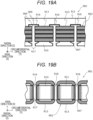
- FIG. 19A is a partial plan view of a stator coil 902 according to the related art as viewed from an axial direction
- FIG. 19B is a partial side view of the stator coil 902 according to the related art as viewed from a radial direction (slot opening 917 side).
- a stator 901 according to the related art includes a cylindrical stator core 911 and a stator coil 902 attached to the stator core 911.
- the stator 901 has a cylindrical shape
- the stator 901 is schematically illustrated in a linear shape in FIGS. 19A and 19B .
- a plurality of teeth 915 are formed in the stator core 911, and slots 916 are formed between the teeth 915.
- the stator core 911 is divided into a plurality of parts in the circumferential direction.
- the stator core 911 is configured by disposing a plurality of split cores in the circumferential direction, and a split core joint 905, which is a boundary surface between the split cores adjacent to each other, is formed between the split cores.
- An insulation material 907 is attached to the slot, and the coil 913 of concentrated winding is attached to each of the plurality of teeth 915 via the insulation material 907.
- the coil 913 is formed by spirally winding a conductive wire around the teeth 915.
- the plurality of coils 913 are connected to each other via a connection wiring (hereinafter, crossover wires) provided at the coil end.
- the stator coil 902 is formed by connecting the plurality of coils 913 via the crossover wires.
- the rotating electrical machine In a case where the rotating electrical machine is driven at a high speed and a high frequency, it is desirable to form the coil 913 with a flat copper wire (a square wire or the like) in order to reduce an AC copper loss generated in the coil.
- a flat copper wire square wire or the like
- a size of the rotating electrical machine is large since a disposition space of the crossover wires connecting the coils 913 wound around the teeth 915 are secured axially outside of the stator core 911.
- the rotating electrical machine according to the present embodiment solves the above problem on the basis of the following concept.
- a stator core having an open slot structure is excellent from the viewpoint of ease of assembling a coil to the stator core, but a stator core having a semi-closed slot structure (a structure in which teeth protrude in a circumferential direction in a gap surface) is excellent from the viewpoint of reducing a torque pulsation.
- the semi-closed slot structure is a structure in which a flange protruding in the circumferential direction is provided at the tip of the tooth, and the open slot structure is a structure in which the flange is not provided.
- a stator core has a semi-closed slot structure in a rotating electrical machine having concentrated winding
- a conductive wire is wound around a tooth by using a winding nozzle or a coil of one winding is attached to a tooth of a split core, but in this method, there is a problem that it is difficult to increase a space factor of a coil in a slot by forming a dead space as described above. Therefore, the present inventors have devised a configuration in which coils of one winding are divided into segment coils for a rotating electrical machine having concentrated winding and fractional slots in which two or more sets of in-phase coils are continuous in the circumferential direction.
- the segment coils can also be attached to a rotating electrical machine having a semi-closed slot structure, and thus a torque pulsation can be reduced.
- connection portion between segment coils In order to ensure the reliability of a connection portion between segment coils, it is necessary to dispose the connection portion between the segment coils in a portion that can be visually inspected and can be physically accessed. It is necessary to eliminate crossover wires in order to achieve space saving. Therefore, the present inventors have devised a configuration in which a connection portion between segment coils is provided at a coil end terminal such that connection work can be easily performed from the axial direction or the radial direction of a stator. The present inventors have devised a configuration in which a conventional crossover wire for connecting coils wound around each tooth can be eliminated by connecting segment coils to each other to form a wavy coil and laminating and disposing a plurality of wavy coils in a radial direction of a stator.
- an operator such as an inspector or a maintenance operator can visually inspect the connection portion between the segment coils and can physically access the connection portion.
- the cost of the rotating electrical machine can be reduced. Since the crossover wire for connecting the coils wound around each tooth can be eliminated, the rotating electrical machine can be downsized.
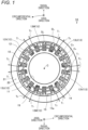
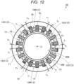
- FIG. 1 is a schematic plan view of a rotating electrical machine 1A including an outer-rotation-type rotor 20 as viewed from an axial direction.
- FIG. 1 different hatching is applied to each phase coil 13 for better understanding of dispositions of a plurality of phase coils 13 (U-phase coils 13U, V-phase coils 13V, and W-phase coils 13W).
- the rotating electrical machine 1A is an outer-rotation-type rotating electrical machine including a cylindrical stator 10 and a cylindrical rotor 20 that is disposed on a radially outer side of the stator 10 with a gap 19 interposed therebetween and is rotatably supported with respect to the stator 10.
- the rotor 20 rotates about a rotation axis C.
- a direction parallel to a rotation axis (rotation center axis) C of the rotor 20 will be referred to as an "axial direction”
- a direction orthogonal to the rotation axis C of the rotor 20 and centered on the rotation axis C of the rotor 20 will be referred to as a "radial direction”
- a direction centered on the rotation axis C of the rotor 20 will be referred to as a "circumferential direction”.
- the stator 10 and the rotor 20 have the same central axis.
- the rotor 20 includes a cylindrical rotor core 21 and a plurality of permanent magnets (not illustrated) fixed to the rotor core 21.
- the rotor core 21 is formed, for example, by laminating a plurality of magnetic steel sheets having an annular shape.
- the rotor core 21 may be formed by compression-molding a powder magnetic material such as a powder magnetic core.
- the permanent magnet is disposed in the circumferential direction of the rotor core and forms a magnetic pole in the circumferential direction.
- the magnetic pole may be formed of a single permanent magnet or may be formed of a plurality of permanent magnets.
- the stator 10 includes a cylindrical stator core 11 and a stator coil 12 attached to the stator core 11.
- the stator coil 12 includes a plurality of phase coils 13 (U-phase coils 13U, V-phase coils 13V, and W-phase coils 13W).
- the rotating electrical machine 1A operates as an electric motor that rotates the rotor 20 by supplying a three-phase alternating current to the stator coils 12 attached to the stator core 11.
- the rotating electrical machine 1A may be driven by external energy to operate as a generator and output generated power based on a three-phase alternating current. That is, the rotating electrical machine 1A may have both a function of an electric motor that generates rotational torque on the basis of electric energy and a function of a generator that generates power on the basis of mechanical energy.
- the stator core 11 includes an annular back yoke 14, a plurality of teeth 15 protruding radially outward from the back yoke 14, and a plurality of slots SL provided between the teeth 15.
- the plurality of teeth 15 and the plurality of slots SL are repeatedly formed in the circumferential direction of the stator core 11.
- the teeth 15 and the slots SL are formed in the axial direction on the outer circumferential portion of the stator core 11.
- the stator core 11 may be configured by an integrated core in which the plurality of teeth 15 and the back yoke 14 are integrally molded, or may be divided into a plurality of pieces as long as magnetic characteristics do not significantly deteriorate for the purpose of improving a material yield.
- the stator core 11 is formed, for example, by laminating a plurality of magnetic steel sheets having an annular shape.
- the stator core 11 may be formed by compression-molding a powder magnetic material such as a powder magnetic core.
- the slot SL of the stator core 11 has a semi-closed slot shape including a flange 15a in which the teeth 15 protrude in the circumferential direction in the gap surface.
- the plurality of phase coils 13 (U-phase coils 13U, V-phase coils 13V, and W-phase coils 13W) configuring the stator coil 12 are mounted in the slots SL.
- the phase coil 13 has an in-slot conductor Cs disposed inside the slot SL and a coil end (an out-of-slot conductor) Ce disposed outside the slot SL.
- Each phase coil 13 is provided with lead-out portions T1 and T2 for input and output connected to an external circuit (not illustrated) including an inverter device and the like.
- the U-phase coil 13U, the V-phase coil 13V, and the W-phase coil 13W are disposed to be shifted by 120° in terms of electrical angle in the circumferential direction of the stator 10.
- phases of input current fundamental wave components are different from each other by 120°.
- FIG. 1 illustrates the rotating electrical machine 1A having 16 poles and 18 slots as an example, as described above, a pole slot combination may be any combination as long as the rotating electrical machine has a configuration of concentrated winding and fractional slots.
- a shape and a disposition of the segment coils configuring the phase coil 13 and a connection structure between the segment coils will be described in detail with reference to the drawings, but a pole slot combination is different from that illustrated in FIG. 1 .
- FIGS. 2A to 6B A specific example of the configurations of the stator core 11 and the phase coil 13 will be described with reference to FIGS. 2A to 6B .
- the stator 10 has a cylindrical shape, the stator 10 is schematically illustrated in a linear shape in each drawing.
- Each configuration will be as appropriate described with the axial direction of the rotating electrical machine 1A as an X-axis direction, the circumferential direction of the rotating electrical machine 1A as a Y-axis direction, and the radial direction of the rotating electrical machine 1A as a Z-axis direction.
- FIG. 2A is a view of a part of the phase coil 13 disposed in a first layer L1 of the stator core 11 as viewed from one side in the axial direction (the upper side of FIG. 2B ).
- FIG. 2A is, for reference, an enlarged sectional view in a case where the phase coil 13 is disposed in each layer (L1 to L4) of the slot SL.
- FIG. 2B is a view of a part of the phase coil 13 disposed in the first layer L1 of the stator core 11 as viewed from the radial direction.
- FIG. 2C is a diagram for describing the assembly of segment coils Sc disposed in the first layer L1 of the stator core 11.
- FIG. 3 is a diagram for describing a configuration of the segment coil Sc.
- one coil winding (one cycle of wave winding) is configured by two segment coils Sc, and wave winding in a plurality of cycles is further arranged in the circumferential direction. Therefore, the same alphabetical lower case code is written at the end of the illustrated code for elements configuring the same cycle such that the wave winding can be identified for each cycle.
- an element configuring the wave winding in the first cycle is denoted by the alphabetical lowercase letter a at the end of the illustrated reference sign
- an element configuring the wave winding in the second cycle is denoted by the alphabetical lowercase latter b at the end of the illustrated reference sign.
- the stator core 11 has a plurality of slots SL (SL1, SL2, SL3..) in the circumferential direction.
- a plurality of segment coils Sc are disposed in a line of layers in the radial direction in the slot SL.
- the inside of the slot SL is divided into four conductor accommodating portions (layers).
- the conductor accommodating portions (layers) are referred to as a first layer L1, a second layer L2, a third layer L3, and a fourth layer L4 in order from the back yoke 14 side toward the tip side of the tooth 15 (the radial opening 17 side of the slot SL). That is, the plurality of segment coils Sc are disposed in each of the plurality of layers (the first layer L1 to the fourth layer L4) arranged in a line in the radial direction in the slot SL.
- an insulation material 7 such as insulation paper or an insulation resin bobbin is disposed in the slot SL to surround the plurality of segment coils Sc.
- Surfaces of metal conductors 8 of the plurality of segment coils Sc are coated with an insulation film 9 such as an epoxy resin in order to ensure insulation between the segment coils Sc adjacent in the radial direction in the slot SL.
- the plurality of segment coils Sc configuring the phase coil 13 are formed by connecting a first segment coil 110 disposed in a predetermined layer in a predetermined slot SL to a second segment coil 120 disposed in the predetermined layer in a slot (adjacent slot) SL adjacent to the predetermined slot SL.
- a shape of the segment coil Sc will be described in detail with reference to FIG. 3 before describing a method of connecting the segment coils with reference to FIGS. 2A to 2C .
- each of the first segment coil 110 and the second segment coil 120 is an L-shaped single component having a predetermined thickness t.
- the first segment coil 110 and the second segment coil 120 have a configuration in which the thickness t in the radial direction is smaller than the width in the circumferential direction or the width in the axial direction in a cross section orthogonal to an energization direction.
- a punching process of punching a conductor plate to form an L-shaped conductor piece may be adopted in a step of manufacturing the first segment coil 110 and the second segment coil 120.
- a conductor piece of which the degree of freedom in shape in the XY plane is high and which has a complicated shape can be easily formed, and thus the number of manufacturing steps of the first segment coil 110 and the second segment coil 120 can be reduced.
- the first segment coil 110 includes a first region 111 having a linear portion 811 disposed in the slot SL and a projection 810 protruding from one end side (the lower side in the drawing) of the linear portion 811 to the outside of the slot SL, and a second region 112 formed to extend from the other end side (the upper side in the drawing) of the linear portion 811 toward one side (the right side in the drawing) in the circumferential direction and change in a position in the radial direction outside the slot SL on the other end side of the linear portion 811.
- the linear portion 811 corresponds to the in-slot conductor Cs disposed inside the slot SL of the stator core 11, and the projection 810 and the second region 112 correspond to the coil end Ce disposed outside the slot SL of the stator core 11.
- the first region 111 is formed linearly to be inserted into the slot SL of the stator core 11 from the axial direction.
- the tip of the projection 810 that is, the tip of the first region 111 will be referred to as a first end 113.
- the second region 112 is formed in a stepped shape (crank shape).
- the tip of the second region 112 will be referred to as a second end 114.
- the second region 112 includes a base 812 connected to the other end side (the upper side in the drawing) of the linear portion 811, a circumferential extension 813 extending from the base 812 toward one side (the right side in the drawing) in the circumferential direction, an axial extension 814 extending from the circumferential extension 813 toward the axial outside (the upper side in the drawing) of the stator core 11, and a second end 114 connected to the axial extension 814.
- the second end 114 extends from the axial extension 814 toward one circumferential direction side (the right side in the drawing).
- the second region 112 includes the base 812 that extends from the linear portion 811 with the same plate width and extends by a predetermined length from the first region 111 to the axial outside (the upper side in the drawing), the circumferential extension 813 bent by 90° from the base 812 to one side (the right side in the drawing) in the circumferential direction and extending by a predetermined length in the circumferential direction, the axial extension 814 bent by 90° from the circumferential extension 813 to the axial outside (the upper side in the drawing) and extending by a predetermined length in the axial direction, and the second end 114 bent by 90° from the axial extension 814 to one side (the right side in the drawing) in the circumferential direction and extending by a predetermined length in the circumferential direction.
- the second region 112 has a step shape (crank shape).
- the first region 111 is located on the lower side
- the second region 112 is located on the upper side
- the first segment coil 110 has a stepped shape in which the base 812 has a first step and the axial extension 814 has a second step.
- the first region 121 is located on the upper side
- the second region 122 is located on the lower side
- the second segment coil 120 has a stepped shape in which the axial extension 824 has the first step and the base 822 has the second step.
- a plurality of bent portions (a first bent portion 815 and second a bent portion 816) for disposing the second end 114 at positions shifted radially inward with respect to the linear portion 811 are formed in the second region 112. That is, the position of the second region 112 in the radial direction continuously changes between the linear portion 811 and the second end 114 by forming the bent portion (815, 816). For example, the position of the second end 114 is shifted in the radial direction (Z-axis direction) by the thickness t of the segment coil Sc (that is, by one layer).
- the circumferential extension 813 and the axial extension 814 have an inclination angle with respect to the base 812 by forming the first bent portion 815 between the circumferential extension 813 and the base 812.
- the second end 114 has an inclination angle with respect to the axial extension 814 by forming the second bent portion 816 between the second end 114 and the axial extension 814.
- the first segment coil 110 and the second segment coil 120 are disposed such that a positional relationship between the first region 111 and the second region 112 is opposite in the axial direction, and have shapes that are mirror-symmetrical to each other.
- the second segment coil 120 includes a first region 121 having a linear portion 821 disposed in the slot SL and a protrusion 820 protruding from one end side (the upper side in the drawing) of the linear portion 821 to the outside of the slot SL, and a second region 122 formed to extend from the other end side (the lower side in the drawing) of the linear portion 821 toward one side (the right side in the drawing) in the circumferential direction and change in a position in the radial direction outside the slot SL on the other end side of the linear portion 821.
- the tip of the protrusion 820 that is, the tip of the first region 121 will be referred to as a first end 123
- the tip of the second region 122 will be referred to
- the second region 122 includes a base 822 connected to the other end side (the lower side in the drawing) of the linear portion 821, a circumferential extension 823 extending from the base 822 toward one side (the right side in the drawing) in the circumferential direction, an axial extension 824 extending from the circumferential extension 823 toward the axial outside (the lower side in the drawing) of the stator core 11, and a second end 124 connected to the axial extension 824.
- the second end 124 extends from the axial extension 824 toward one circumferential direction side (the right side in the drawing).
- the second region 122 has a configuration (transition) in which the position in the radial direction continuously changes between the linear portion 821 and the second end 124 by forming the bent portion (825, 826).
- the second end 114 of the first segment coil 110 can be disposed to overlap the first end 123 of the second segment coil 120 in the radial direction.
- the second region 112 of the first segment coil 110 and the second region 122 of the second segment coil 120 both extend in one circumferential direction.
- the first segment coil 110a, the second segment coil 120a, and the first segment coil 110b are sequentially disposed in the first layer L1 of each of the first slot SL1, the second slot SL2, and the third slot SL3.
- the second end 114a of the first segment coil 110a is disposed adjacent to the first end 123a of the second segment coil 120a in the radial direction and connected to each other.
- the second end 124a of the second segment coil 120a is disposed to be adjacent to the first end 113b of the first segment coil 110b in the radial direction and connected to each other.
- the first segment coils 110a, 110b, ..., and the second segment coils 120a, 120b, ... are alternately connected in the circumferential direction, and thus a wavy coil 31 is formed in the first layer L1.
- the wavy coil 31 has a wavy shape in which a crest portion 38 protruding in one axial direction and a valley portion 39 protruding in the other axial direction are alternately disposed at both ends of the coil end in the circumferential direction.
- the second end 114a of the first segment coil 110a is displaced by one layer in the radial direction with respect to the first region 111a outside the slot SL, overlaps the first end 123a of the second segment coil 120a in the radial direction, and is electrically and mechanically connected via a conductive portion (hereinafter, referred to as a linear conductive portion) 125a extending linearly in the circumferential direction.
- a linear conductive portion hereinafter, referred to as a linear conductive portion
- the linear conductive portion 125a corresponds to a welding line formed through electron beam welding, laser welding, or the like. Since the linear conductive portion 125a is located at the axial end of the coil end Ce, visual inspection by an operator and appearance inspection by an automatic inspection machine are facilitated. Since the linear conductive portion 125a can be physically accessed from the outside of the stator 10, it is easy for an operator to repair a connection portion, perform inspection with contact, and the like.
- conductive portion (hereinafter, referred to as a planar conductive portion) 126a having a planar shape may be provided instead of the linear conductive portion 125a.
- the planar conductive portion 126a is located at the axial end of the coil end Ce of the first segment coil 110a and the second segment coil 120a, and electrically and mechanically connects facing surfaces of the second end 114a of the first segment coil 110a and the first end 123a of the second segment coil 120a.
- planar conductive portion 126a Since the planar conductive portion 126a is located at the axial end of the coil end Ce, visual inspection by an operator and appearance inspection by an automatic inspection machine are facilitated. Since the planar conductive portion 126a can be physically accessed from the outside of the stator 10, it is easy for an operator to repair a connection portion, perform inspection with contact, and the like.
- the second end 114a of the first segment coil 110a and the first end 123a of the second segment coil 120a may be connected via both the linear conductive portion 125a and the planar conductive portion 126a.
- the reliability of the connection portion between the first segment coil 110a and the second segment coil 120a can be improved.
- the manufacturing cost of the rotating electrical machine 1A can be reduced.
- the conductive portions may include at least any one of a conductive paste, a conductive sheet, a conductive adhesive, a solder, a silver brazing material, and metal plating. Since a part or the whole of the conductive portions (the linear conductive portion 125a and the planar conductive portion 126a) is formed by these conductive members, conductivity between the first segment coil 110a and the second segment coil 120a can be improved.
- the conductivity between the first segment coil 110a and the second segment coil 120a is improved by a metal plating material.
- the planar conductive portion 126a may be formed by using a metal plating material having a relatively low melting point such as zinc or tin. In this case, in a state in which the metal plating material is disposed between the second end 114a of the first segment coil 110a and the first end 123a of the second segment coil 120a, heating treatment is performed until the metal plating material is melted.
- the metal plating material solidified due to cooling is formed as the planar conductive portion 126a, and the second end 114a and the first end 123a are electrically and mechanically connected via the metal plating material (planar conductive portion 126a).
- the first region 111 of the first segment coil 110 is inserted into the first layer L1 of the first slot SL1 from one side (the upper side in the drawing) in the axial direction, and the first end 113 and the second end 114 are disposed outside the slot SL.
- the first region 121 of the second segment coil 120 is inserted into the first layer L1 of the second slot SL2 from the other side in the axial direction (the lower side in the drawing), and the first end 123 and the second end 124 are disposed outside the slot SL.
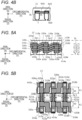
- FIG. 4A is a partial side view of a coil end of a stator according to a comparative example of Embodiment 1
- FIG. 4B is a partial plan view of the stator according to the comparative example of Embodiment 1.
- a tip surface 912Y of a second region 912 of a first segment coil 910 and a side surface 923Y of the tip of a first end 923 of a second segment coil 920 are disposed to face each other in the circumferential direction (Y direction).
- a conductive portion 925 formed through welding or the like is dotted, the contact resistance increases compared with the present embodiment, and there is a possibility that local heat is generated in the conductive portion 925.
- the position of the second region 112a in the radial direction changes (transitions) between the first region 111a and the second end 114a by forming the bent portions 815 and 816. Consequently, the segment coils 110a and 120a adjacent to each other in the circumferential direction can be connected via one or both of the linear conductive portion 125a and the planar conductive portion 126a described above. Therefore, according to the present embodiment, the contact resistance can be reduced compared with the comparative example, and local heat can be prevented from being generated in the conductive portions 125a and 126a. As a result, the rotating electrical machine 1A according to the present embodiment can improve the product reliability compared with the rotating electrical machine according to the comparative example.
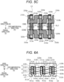
- FIG. 5A is a partial plan view of the stator 10 as viewed from the axial direction.
- FIG. 5B is a partial side view of the stator 10 as viewed from the gap 19 side.
- FIG. 5C is a view in which the segment coil Sc disposed in the fourth layer L4 is omitted in the partial side view of FIG. 5B .
- FIGS. 5A to 5C A difference from FIGS.
- each coil can be disposed without interference even in a state in which all coils are assembled, and thus a detailed structure thereof will be described below.
- the rotating electrical machine 1A in the rotating electrical machine 1A according to the present embodiment, not only the first segment coil 110 and the second segment coil 120 are alternately disposed in the first layer L1 of each slot SL arranged in the circumferential direction, but also the first segment coils 210, 310, and 410 and the second segment coils 220, 320, and 420 are similarly disposed in the second layer L2 to the fourth layer L4 of each slot SL arranged in the circumferential direction.
- the first segment coils and the second segment coils are alternately disposed in the radial direction.
- the first segment coil 110a is disposed in the first layer L1
- the second segment coil 220a is disposed in the second layer L2
- the first segment coil 310a is disposed in the third layer L3
- the second segment coil 420a is disposed in the fourth layer L4.
- the second slot SL2 adjacent to the first slot SL1 the second segment coil 120a is disposed in the first layer L1
- the first segment coil 210a is disposed in the second layer L2
- the second segment coil 320a is disposed in the third layer L3
- the first segment coil 410a is disposed in the fourth layer L4.
- a method of connecting the adjacent slots SL is similar to that in FIGS. 2A and 2B for the first layer L1 and the third layer L3.
- the first segment coil 110a of the first slot SL1 and the second segment coil 120a of the second slot SL2 are connected.
- the third layer L3 the first segment coil 310a of the first slot SL1 and the second segment coil 320a of the second slot SL2 are connected.
- the second layer L2 and the fourth layer L4 a basic connection configuration is similar to that in FIGS. 2A and 2B , but dispositions in the circumferential direction of the first segment coil and the second segment coil are exchanged.
- the second segment coil 220a is disposed in the first slot SL1, the first segment coil 210a is disposed in the second slot SL2, and both are connected to each other.
- the second segment coil 420a is disposed in the first slot SL1, the first segment coil 410a is disposed in the second slot SL2, and both are connected to each other.
- the segment coils Sc do not spatially interfere with each other at the coil end Ce.
- the coil end of the segment coil Sc is displaced in the radial direction by one layer with respect to the linear portion disposed in the slot. Therefore, for example, as illustrated in FIGS. 5A and 5B , the second end 414a of the first segment coil 410a disposed in the fourth layer L4 of the second slot SL2 is disposed on an axis of the third layer L3 of the third slot SL3.
- the axis of the layer refers to a virtual straight line parallel to the axial direction passing through the layer.
- the second region 412a of the first segment coil 410a is formed in a step shape (crank shape). Therefore, when the first segment coil 410a is assembled to the stator core 11, the second end 414a is disposed away from one axial end surface (I end surface) of the stator core 11 by a predetermined distance X1.
- the predetermined distance X1 is longer than a distance (that is, a protruding height of the base 812 from the slot SL3) X0 from one axial end surface (I end surface) of the stator core 11 to one axial end surface (upper end surface in the drawing) of the base 812.
- the second end 414a of the first segment coil 410a disposed in the fourth layer L4 of the second slot SL2 is disposed away from the axial outside of the base 812 of the second region of the first segment coil 310b disposed in the third layer L3 of the third slot SL3. That is, the first region 311b and the base 812 of the first segment coil 310b and the second end 414a of the first segment coil 410a coexist on the axis of the third layer L3 of the third slot SL3.
- the above configuration is also similar on the other axial end side (II end side) of the stator core 11.
- the second end 424a of the second segment coil 420a disposed in the fourth layer L4 of the first slot SL1 is disposed away from the axial outside of the base 812 of the second region of the second segment coil 320a disposed in the third layer L3 of the second slot SL2. That is, the first region 321a of the second segment coil 320a and the base 812, and the second end 424a of the second segment coil 420a coexist on the axis of the third layer L3 of the second slot SL2.
- the second end 414a of the first segment coil 410a disposed in a predetermined layer (for example, the fourth layer L4) of a predetermined slot (for example, the second slot SL2) is formed to extend toward one side in the circumferential direction and change in a position in the axial direction stepwise so as not to interfere with the second region of the first segment coil 310b disposed in an adjacent layer (for example, the third layer L3) of an adjacent slot (for example, the third slot SL3). Consequently, at the coil end on the I end side, the segment coils Sc can be assembled to the stator core 11 without interference between the first segment coils. In the same manner for the coil end on the II end side, the segment coils Sc can be assembled without interference between the second segment coils.
- the plurality of first segment coils have the same shape.
- the plurality of second segment coils have the same shape.
- at least two of the plurality of segment coils Sc disposed in the predetermined slot SL have the same shape.
- the first segment coil and the second segment coil have mirror-symmetrical shapes, and have the same shape before the bent portions 815, 816, 825, and 826 (see FIG. 3 ) are formed.
- the segment coils Sc can be assembled to the stator core 11 without interference between the first segment coils having the same shape.
- the segment coils Sc can be assembled to the stator core 11 without interference between the second segment coils having the same shape.
- FIGS. 6A and 6B are circuit diagrams corresponding to the configuration of the phase coil 13 in FIGS. 5A and 5B , in which FIG. 6A is a circuit diagram of the stator 10 as viewed from the axial direction, and FIG. 6B is a circuit diagram of the stator as viewed from the gap 19 side.
- a filled circle "•" in FIG. 6B schematically represents a connection portion between the first segment coil and the second segment coil, and an arrow represents a direction of a current.
- the first segment coil is indicated by a solid line
- the second segment coil is indicated by a dashed line.
- FIG. 6B also illustrates a schematic diagram for describing a disposition configuration of the wavy coils 31 and 32 in the first layer L1 and the second layer L2.
- the first segment coils 110 and the second segment coils 120 are alternately connected in the circumferential direction, and thus the wavy coils 31 in which the crest portions 38 and the valley portions 39 are alternately disposed in the circumferential direction are formed.
- the wavy coils 32, 33, and 34 in which the crest portions 38 and the valley portions 39 are alternately disposed at both ends of the coil end in the circumferential direction are formed in the second layer L2 to the fourth layer L4. That is, the wavy coils 31 to 34 are respectively formed in the plurality of layers (L1 to L4).
- the circumferential positions of the crest portion 38 and the valley portion 39 of the wavy coil 31 disposed in the first layer L1 and the circumferential positions of the crest portion 38 and the valley portion 39 of the wavy coil 32 disposed in the second layer L2 are shifted by one slot pitch.
- the circumferential positions of the crest portion 38 and the valley portion 39 of the wavy coil 33 disposed in the third layer L3 and the circumferential positions of the crest portion 38 and the valley portion 39 of the wavy coil 34 disposed in the fourth layer L4 are shifted by one slot pitch.
- connection portions between the second segment coils 120a and 320a disposed in the odd layers (L1, L3) of the second slot SL2 and the first segment coils 110a and 310a disposed in the odd layers (L1, L3) of the first slot SL1 are disposed on the I end side of the second slot SL2.
- connection portions of the first segment coils 210a and 410a disposed in the even layers (L2, L4) of the second slot SL2 is not disposed on the I end side of the second slot SL2, are bent from the second slot SL2 toward the third slot SL3 side, and are connected to the second segment coils 220b and 420b disposed in the even layers (L2, L4) of the third slot SL3 on the I end side of the third slot SL3.
- interference between the segment coils Sc on the I end side of the second slot SL2 is avoided.
- interference between the segment coils Sc on the I end side of the other slots SL is avoided.
- connection portions between the first segment coils 210a and 410a disposed in the even layers (L2, L4) of the second slot SL2 and the second segment coils 220a and 420a disposed in the even layers (L2, L4) of the first slot SL1 are disposed on the II end side of the second slot SL2.
- connection portions of the second segment coils 120a and 320a disposed in the odd layers (L1, L3) of the second slot SL2 are not disposed on the II end side of the second slot SL2, are bent from the second slot SL2 toward the third slot SL3 side, and are connected to the first segment coils 110b and 310b disposed in the odd layers (L1, L3) of the third slot SL3 on the II end side of the third slot SL3.
- interference between the segment coils Sc on the II end side of the second slot SL2 is avoided.
- the interference between the segment coils Sc on the II end side of the other slots SL is avoided.
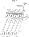
- FIG. 7 is a partial perspective view of the stator 10 having the slot SL configured with six layers.
- the slot SL of the stator 10 includes a first layer L1 to a sixth layer L6.
- connection portions between the second segment coils 120a, 320a, and 520a disposed in the odd layers (L1, L3, L5) of the second slot SL2 and the first segment coils 110a, 310a, and 510a disposed in the odd layers (L1, L3, L5) of the first slot SL1 are disposed on the I end side of the second slot SL2.
- connection portions of the first segment coils 210a, 410a, and 610a disposed in the even layers (L2, L4, L6) of the second slot SL2 are not disposed, and are bent from the second slot SL2 toward the third slot SL3 side, and are connected to the second segment coils 220b, 420b, and 620b disposed in the even layers (L2, L4, L6) of the third slot SL3 on the I end side of the third slot SL3.
- interference between the segment coils Sc on the I end side of the second slot SL2 is avoided.
- interference between the segment coils Sc on the I end side of the other slots SL is avoided.
- interference between the segment coils Sc on the II end side of each slot SL is avoided.
- the segment coils Sc do not interfere with each other at the coil end Ce, and a coil disposition of concentrated winding and fractional slots can be realized by wave winding.
- the linear portions of the segment coils Sc are disposed in a line of layers in the slot SL, and thus a space factor of the segment coils Sc in the slot SL can be increased. Therefore, according to the present embodiment, the efficiency and output of the rotating electrical machine 1A can be improved without increasing a size of the rotating electrical machine 1A.
- the first segment coil 110 can be inserted into the slot SL from one end side in the axial direction
- the second segment coil 120 can be inserted into the slot SL from the other end side in the axial direction.
- the stator core 11 having a semi-closed slot structure may be adopted. Therefore, the rotating electrical machine 1A according to the present embodiment can reduce a torque pulsation compared with a rotating electrical machine having a stator core having an open closed slot structure.
- the coil disposition of concentrated winding and fractional slot can be realized by wave winding by using the first segment coil 110 and the second segment coil 120. Consequently, it is possible to eliminate the need for a crossover wire for connecting the concentrated winding coils spirally wound around each of the teeth 15 and thus to achieve downsizing of the rotating electrical machine 1A.
- each of the first segment coil 110 and the second segment coil 120 in the radial direction is smaller than the width thereof in the circumferential direction or the axial direction in the cross section orthogonal to the energization direction.
- materials of the first segment coil 110 and the second segment coil 120 can be efficiently manufactured through a punching process from a conductor plate such as a copper plate. Therefore, according to the present embodiment, it is possible to reduce the number of manufacturing steps and the manufacturing cost.
- the first segment coil 110 and the second segment coil 120 are each an L-shaped single component. Therefore, it is possible to reduce the number of manufacturing steps and the manufacturing cost compared with a case of forming the segment coil Sc by bundling and molding a plurality of bare wires.
- a first segment coil (410a) is disposed in a predetermined layer (fourth layer L4) of a predetermined slot (second slot SL2) of the stator core 11
- a second segment coil (320a) is disposed in an adjacent layer (third layer L3) adjacent to the predetermined layer (fourth layer L4) of the predetermined slot (second slot SL2)
- a second segment coil (420b) is disposed in the predetermined layer (fourth layer L4) of an adjacent slot (third slot SL3) adjacent to the predetermined slot (second slot SL2)
- a first segment coil (310b) is disposed in an adjacent layer (third layer L3) of the adjacent slot (third slot SL3) .
- a second region (412a) of the first segment coil (410a) disposed in the predetermined layer (fourth layer L4) of the predetermined slot (second slot SL2) is formed to extend toward one side in the circumferential direction and change in a position in the axial direction such that a second end (414a) of the first segment coil (410a) does not interfere with the second region of the first segment coil (310b) disposed in the adjacent layer (third layer L3) of the adjacent slot (third slot SL3).
- the segment coils Sc can be assembled to the stator core 11 without interference between the first segment coils.
- a positioning step before welding can be easily completed by simply inserting the segment coil Sc molded in advance through a punching process on a conductor plate or the like into the slot SL of the stator core 11. Therefore, it is possible to prevent the insulation material 7 such as insulation paper and the insulation film 9 of the segment coil Sc from being damaged, and thus to prevent the occurrence of an insulation failure. Since it is not necessary to perform bending or the like on the segment coil Sc after inserting the segment coil Sc into the slot SL, it is also possible to solve the problem that welding defects occur due to variations in bending angles caused by spring back or the like.
- segment coils Sc are connected through electron beam welding or laser welding, a linear portion extending in the axial direction required for tungsten-inert gas welding (TIG welding) is unnecessary. Therefore, according to the present embodiment, sizes and weights of the stator 10 and the rotating electrical machine 1A can be reduced. According to the present embodiment, a caulking fitting for preventing positional deviation at the connection portion is also unnecessary. Therefore, since the number of components and the number of work steps can be reduced, the manufacturing cost of the rotating electrical machine 1A can be reduced.
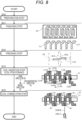
- FIG. 8 is a diagram for describing a step of manufacturing the stator 10 of the rotating electrical machine 1A.
- the method of manufacturing the stator 10 includes a preparation step S10, a punching step S11, a pressing step S12, a coil insertion step S13, and a coil connection step S14.
- a plate-like conductor plate 70 made of a conductive material such as copper or aluminum and having a predetermined thickness is prepared as a material of the segment coil Sc.
- a mold for punching the conductor plate 70 is prepared. It is preferable to employ a mold capable of forming a plurality of L-shaped conductor pieces 71 through one punching process.
- the preparation step S10 is completed, the process proceeds to a punching step S11.
- the conductor plate 70 is punched by using the mold to produce a plurality of L-shaped conductor pieces 71.
- the punching process is characterized by a high degree of freedom in two-dimensional processing of the conductor plate 70.
- the step-shaped second region 112 can be easily formed in the punching step 511.
- the thickness of the conductor plate 70 is a thickness of the segment coil Sc, that is, a radial dimension of the segment coil Sc assembled to the stator core 11.
- the conductor piece 71 formed in the punching step S11 is pressed by a mold 79.
- the bent portions 815 and 816 are formed in the conductor piece 71, and thus the first segment coil 110 is manufactured.
- the conductor piece 71 formed in the punching step S11 is pressed, and thus the second segment coil 120 having the bent portions 825 and 826 is also manufactured.
- the process proceeds to the coil insertion step S13.
- an insulation film forming process is performed prior to the coil inserting step S13.
- an insulation film 9 is formed on each segment coil Sc in advance.
- the plurality of segment coils Sc are inserted into the slots SL of the stator core 11 and positioned.
- the first segment coil 110 is inserted into the slot SL from one axial end side (the upper side in the drawing) of the stator core 11, and the second segment coil 120 is inserted into the slot SL from the other axial end side (the lower side in the drawing) of the stator core 11.
- the second end 114a of the first segment coil 110a and the first end 123a of the second segment coil 120a are disposed to overlap each other in the radial direction.
- the axial end surface of the second end 114a and the axial end surface of the first end 123a are disposed to be flush with each other, and this portion becomes a connection location Wx formed through welding.
- the second end 124a of the second segment coil 120a and the first end 113b of the first segment coil 110b are disposed to overlap each other in the radial direction.
- the axial end surface of the second end 124a and the axial end surface of the first end 113b are disposed to be flush with each other, and this portion becomes a connection location Wx formed through welding.
- the same insertion work is repeated in the circumferential direction (in the drawing, up to the work of inserting the second segment coil 120c), and when the coil insertion step S13 is completed, the process proceeds to the coil connection step S14.
- the segment coils Sc are connected to each other at the connection location Wx through, for example, laser welding.
- the insulation film 9 at the connection location Wx of the segment coil Sc is removed in advance.
- laser light 500LB is emitted from an emission unit 500LX of a laser welding machine in the axial direction toward the connection location Wx, and the emission unit 500LX is moved in the circumferential direction to form the linear conductive portions 115 and 125 (see FIG. 2B ).
- the planar conductive portion 126 (see FIG. 2B ) connecting the second end 114 of the first segment coil 110 to the first end 123 of the second segment coil 120 and the planar conductive portion 116 (see FIG.
- the method of manufacturing the rotating electrical machine 1A is a method of manufacturing the stator coil 12 by connecting the plurality of L-shaped segment coils Sc, the method including: a segment forming step (S11, S12) of forming a plurality of the first segment coils 110 and the second segment coils 120 in which one side of the L shape is the first region 111 and the other side of the L shape is the second region 112; a coil insertion step S13 of inserting the first segment coil 110 into the slot SL from one end side in the axial direction of the stator core 11 to cause the tip of the first region 111 to protrude out of the slot SL, disposing the second region 112 to extend from the first region 111 to one side in the circumferential direction, inserting the second segment coil 120 into the slot SL from the other end side in the axial direction of the stator core 11 to cause the tip of the first region 121 to protrude out of the slot SL, disposing the second region 122 to extend from the first region
- the manufacturing method since it is not necessary to form the segment coil Sc after inserting the segment coil Sc into the slot SL of the stator core 11, the number of manufacturing steps can be reduced and a manufacturing facility can be simplified. Since the connection portion between the segment coils Sc is located at the axial end of the coil end Ce of the stator coil 12, it is possible to provide the rotating electrical machine 1A that can be visually inspected and can be physically accessed. Since this manufacturing method includes the punching step S11 of punching the conductor plate 70 to form the conductor piece 71, the segment coil Sc having the coil end Ce (second region 112,122) having a complicated shape can be easily formed.
- a thickness of the segment coil Sc formed by the conductor piece 71 is uniform as a whole.
- the thickness of the in-slot conductor Cs and the thickness of the coil end Ce are substantially the same.
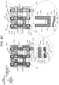
- FIG. 9A is a partial plan view of a stator 10 of Embodiment 2 as viewed from an axial direction.
- FIG. 9B is a partial side view of the stator 10 of Embodiment 2 as viewed from a gap 19 side.
- FIG. 9A is a partial plan view of a stator 10 of Embodiment 2 as viewed from an axial direction.
- FIG. 9B is a partial side view of the stator 10 of Embodiment 2 as viewed from a gap 19 side.
- FIG. 9A is a partial plan view of a stator 10 of Embodiment 2 as viewed from an axial direction.
- FIG. 9B is a partial side view of the stator 10 of Embodiment 2 as viewed from a gap 19 side.
- FIG. 9C is a partial side view of the stator 10 of Embodiment 2 as viewed from the gap 19 side, in which the segment coils 410u and 410w having lead-out portions 400u and 400w and second segment coils 420u and 420w disposed in a fourth layer L4 are omitted.
- Embodiment 2 an example of a structure in which two different types of phase coils 13 (see FIG. 1 ) in the rotating electrical machine 1A according to Embodiment 1 coexist in one slot will be described.
- the present invention also has a feature that the segment coils Sc can be disposed without interference between the phase coils 13 at the coil end Ce at which out-of-phase slots and in-phase slots are arranged in the circumferential direction, and thus a detailed structure thereof will be described.
- One cycle of wave winding of the present invention is basically disposed in the same layer. However, as described above, in order to prevent the phase coils 13 from interfering with each other, it is necessary to have a configuration in which the phase coil transitions to an adjacent layer in one cycle of wave winding in the circumferential end slot of the in-phase coil (a slot coexisting with an out-of-phase coil). A detailed structure thereof will also be described below.
- FIG. 9A illustrates a V-phase slot circumferential end SLv2, a VU-phase coexisting slot SLvu, a U-phase slot circumferential one end SLu1, a U-phase slot circumferential other end SLu2, a UW-phase coexisting slot SLuw, and a W-phase slot circumferential end SLw1 in order from the left.
- the slot SLvu is an out-of-phase slot in which two different types of phase coils 13 (the V-phase coil 13V and the U-phase coil 13U) are accommodated, and similarly, the slot SLuw is also an out-of-phase slot in which two different types of phase coils 13 (the U-phase coil 13U and the W-phase coil 13W) are accommodated.
- the slots SLv2, SLu1, SLu2, and SLw1 are in-phase slots in which only the phase coils 13 of the same type are accommodated. The same applies to FIGS. 9B and 9C .
- the letter u is added to the end of the reference sign of the U-phase segment coil
- the letter w is added to the W-phase segment coil. Since the configurations of the U-phase coil 13U, the V-phase coil 13V, and the W-phase coil 13W are similar, a disposition configuration of the U-phase coil 13U will be described as a representative.
- a linear portion 431u is disposed in the fourth layer L4 of the slot SLu2, and a linear portion 432u is disposed in the third layer L3 of the slot SLuw.
- a coupling portion 433u of the U-shaped coil 430u is disposed on the II end side of the stator core 11.
- the coupling portion 433u is provided with bent portions 835 and 836. Therefore, the coupling portion 433u extends in the circumferential direction from the linear portion 431u toward the linear portion 432u and changes in a position in the radial direction. Therefore, the linear portions 431u and 432u can be respectively disposed in the layers (the fourth layer L4 and the third layer L3) adjacent to each other in the radial direction.
- FIG. 9A A right diagram of FIG. 9A , a right diagram of FIG. 9B , and a right diagram of FIG. 9C illustrate a configuration in which the U-phase slot and the W-phase slot are arranged in the circumferential direction.
- a second end 414u of the first segment coil 410u disposed in the fourth layer L4 of a slot (not illustrated) adjacent on the left side of the slot SLu2 in the drawing is disposed on an axis of the third layer L3 of the slot SLu2 and is disposed to be adjacent to the tip of the linear portion 431u of the segment coil 430u having a U shape (hereinafter, a U-shaped coil; see FIG.
- the second end 414u of the first segment coil 410u and the tip of the linear portion 431u of the U-shaped coil 430u are electrically and mechanically connected via at least one of a linear conductive portion 435u and a planar conductive portion 436u.
- the second end 314u of the first segment coil 310u disposed in the third layer L3 of the slot SLu2 is disposed on the axis of the second layer L2 of the slot SLuw.
- the second end 314u of the first segment coil 310u is disposed to be adjacent to the tip of the linear portion 432u of the U-shaped coil 430u in the radial direction, and is electrically and mechanically connected via at least one of the linear conductive portion 335u and the planar conductive portion 336u.
- FIG. 9A and the left diagram in FIG. 9B illustrate a configuration in which the V-phase slot and the U-phase slot are arranged in the circumferential direction.
- a segment coil 340u having an I shape (hereinafter, an I-shaped coil; see FIG. 9C for the I shape, and details thereof will be described later) is disposed on the II end side of the stator core 11.
- a connection end 341u of the I-shaped coil 340u is disposed on the axis of the second layer L2 of the slot SLu1, and a connection end 342u is disposed on the axis of the third layer L3 of the slot SLvu.
- connection end 341u is disposed to be adjacent to the first end 313u of the first segment coil 310u disposed in the third layer L3 of the slot SLu1 in the radial direction, and is electrically and mechanically connected to the first end 313u via at least one of the linear conductive portion 315u and the planar conductive portion 316u.
- the connection end 342u is disposed to be adjacent to the first end 213u of the first segment coil 210u disposed in the second layer L2 of the slot SLvu in the radial direction, and is electrically and mechanically connected to the first end 213u via at least one of the linear conductive portion 215u and the planar conductive portion 216u.
- the segment coil 410u disposed in the fourth layer L4 of the slot SLvu and the segment coil 110u disposed in the first layer L1 of the slot SLu1 have the same configuration as that the first segment coil, but are provided with lead-out portions 400u and 100u extending in the axial direction from the linear portion.
- the lead-out portions 400u and 100u are connected to an external circuit (not illustrated) including an inverter device or the like via a wiring (not illustrated).
- the U-shaped coil 430u is a conductive member having a U shape, and is manufactured similarly to the first segment coil and the second segment coil, by punching the conductor plate 70 to manufacture a U-shaped conductor piece, and pressing the conductor piece.
- the U-shaped coil 430u includes a pair of linear portions 431u and 432u inserted into the slots SL adjacent in the circumferential direction, and a coupling portion 433u that couples ends of the pair of linear portions 431u and 432u.
- the pair of linear portions 431u and 432u are formed to be parallel to each other, and the coupling portion 433u is formed to be orthogonal to the pair of linear portions 431u and 432u.
- the first bent portion 835 and the second bent portion 836 are formed such that radial positions of the pair of linear portions 431u and 432u are shifted by about one layer in a state in which the pair of linear portions 431u and 432u are inserted into the slots SL.
- An inclined portion 834 inclined with respect to the pair of linear portions 431u and 432u is formed between the first bent portion 835 and the second bent portion 836.
- the I-shaped coil 340u is a conductive member having an I shape (rectangular shape), and is manufactured similarly to the first segment coil and the second segment coil, by punching the conductor plate 70 to manufacture an I-shaped conductor piece, and pressing the conductor piece.
- the I-shaped coil 340u has a connection end 341u connected to the first end 313u of one first segment coil 310u and a connection end 342u connected to the first end 213u of the other first segment coil 210u, of the pair of first segment coils inserted into the slots SL adjacent in the circumferential direction.
- the pair of connection ends 341u and 342u are formed to be parallel to each other.
- the first bent portion 845 and the second bent portion 846 are formed such that radial positions of the pair of connection ends 341u and 342u are shifted by about one layer.
- An inclined portion 844 inclined with respect to the pair of connection ends 341u and 342u is formed between the first bent portion 845 and the second bent portion 846.
- the overall shape of the U-phase coil 13U configured with the plurality of segment coils is as follows.
- the U-phase coil 13U extends in a wave shape (the left diagram in FIG. 9B ) toward one side in the circumferential direction (the right side in the drawing) with the lead-out portion 400u as a start end, and is folded back to the other side in the circumferential direction (the left side in the drawing) while positionally changing (transitioning) from the fourth layer L4 to the third layer L3 due to the U-shaped coil 430u (the right diagram in FIG. 9C ).
- the U-phase coil 13U extends in a wave shape toward the other side in the circumferential direction (the left side in the drawing), and is folded back to one side in the circumferential direction (the right side in the drawing) while positionally changing (transitioning) from the third layer L3 to the second layer L2 due to the I-shaped coil 340u (the left diagram in FIG. 9C ).
- the U-phase coil 13U extends in a wave shape toward one side in the circumferential direction (the right side in the drawing), and is folded back to the other side in the circumferential direction (the left side in the drawing) while positionally changing (transitioning) from the second layer L2 to the first layer L1 due to the U-shaped coil 230u.
- the U-phase coil 13U extends in a wave shape toward the other side in the circumferential direction (the left side in the drawing), and terminates at the lead-out portion 100u.
- a current flowing into the U-phase coil 13U from the lead-out portion 400u located in the U-phase fourth layer L4 flows toward one side in the circumferential direction (the right side in the drawing) through the segment coil (410u, 420u) of the fourth layer L4 as indicated by a solid arrow in the left diagram in FIG. 9B .
- the current flows to the first segment coil 310u of the third layer L3 through the segment coil 410u of the fourth layer L4 and the U-shaped coil 430u, and is folded back to the other side (the left side in the drawing) in the circumferential direction.
- the current flows toward the other side in the circumferential direction through the segment coil (310u, 320u) of the third layer L3 (the left side in the drawing).
- the current flows to the first segment coil 210u disposed in the second layer L2 through the segment coil 310u of the third layer L3 and the I-shaped coil 340u, and is folded back to one side in the circumferential direction (the right side in the drawing).
- the current flows toward one side in the circumferential direction (the right side in the drawing) through the segment coil (210u, 220u) disposed in the second layer L2. Subsequently, the current flows to the first segment coil 110u of the first layer L1 through the U-shaped coil 230u illustrated in the right diagram in FIG. 9A , and is folded back to the other side in the circumferential direction (the left side in the drawing). The current flowing toward the other circumferential direction (the left side in the drawing) through the segment coil (110u, 120u) of the first layer L1 flows to an external circuit through the lead-out portion 100u of the segment coil 110u.
- the U-phase coil 13U is configured by connecting the wavy coils 31 to 34 of the respective layers (L1 to L4) via the U- shaped coils 430u and 230u and the I-shaped coil 340u.
- the V-phase coil 13V and the W-phase coil 13W have the same configuration.
- FIGS. 10A and 10B are circuit diagrams corresponding to the configuration of the phase coil 13 in FIGS. 9A and 9B .
- FIG. 10A is a circuit diagram of the stator 10 as viewed from the axial direction
- FIG. 10B is a circuit diagram of the stator 10 as viewed from the gap 19 side.
- a filled circle "•" in FIG. 10B schematically represents a connection portion of the segment coil Sc, and an arrow represents a direction of a current.
- the first segment coil is indicated by a solid line
- the second segment coil, the U-shaped coil, and the I-shaped coil are indicated by dashed lines.
- the U-shaped coils 230u and 430u are provided to configure a folded portion on one end side in the circumferential direction of the U-phase coil 13U, and the I-shaped coil 340u is provided to configure a folded portion on the other end side in the circumferential direction of the U-phase coil 13U.
- the W-phase first segment coil 410w is disposed in the fourth layer L4
- the linear portion 432u of the U-phase U-shaped coil 430u is disposed in the third layer L3
- the W-phase first segment coil 210w is disposed in the second layer L2
- the linear portion 232u of the U-phase U-shaped coil 230u is disposed in the first layer L1.
- Embodiment 2 it is possible to prevent the phase coils 13 from interfering with each other at a position where the out-of-phase coils are arranged in the radial direction in the rotating electrical machine 1A having the concentrated winding-fractional slot configuration.
- both ends of the U-shaped coil are connected to the respective second ends of the pair of first segment coils through laser welding or the like outside the slot SL, and both ends of the I-shaped coil are connected to the respective first ends of the pair of first segment coils outside the slot SL, so that the phase coil 13 is formed. That is, according to the present embodiment, it is possible to extremely easily dispose the segment coils Sc and connect the segment coils Sc to each other.
- FIG. 11 is a schematic sectional view of an in-wheel type electric wheel 1000 according to Embodiment 3 of the present invention.
- the electric wheel 1000 includes the outer-rotation-type rotating electrical machine 1A described in the above Embodiments 1 and 2 inside a wheel 1020.
- the rotor 20 of the rotating electrical machine 1A is connected to a rotor frame 1030.
- the rotor frame 1030 is connected to the wheel 1020 via a connection member 1040.
- a tire 1010 is fitted to the wheel 1020.
- the wheel 1020 and the rotor 20 are rotatably supported at a shaft 1060.
- the wheel 1020 or the rotor frame 1030 is connected to the shaft 1060 via a bearing 1050.
- the stator 10 of the rotating electrical machine 1A is fixedly supported at the shaft 1060 by a support member (not illustrated), and an electric circuit unit 770 is also mounted on the support member.
- the electric circuit unit 770 supplies electric power to the stator 10 to rotate the rotor 20. Rotation of the rotor 20 is transmitted to the wheel 1020 via the rotor frame 1030 and the connection member 1040. The wheel 1020 is rotated about the shaft 1060.
- the electric wheel 1000 directly drives the wheel 1020 with the rotating electrical machine 1A without using a gear.
- a conventional electric wheel that transmits torque of a rotating electrical machine to a wheel via a gear components such as a bearing are required to support the gear, and thus there is room for improvement in terms of the number of components.
- the conventional electric wheel has a problem that gear wear and noise are large.
- the rotating electrical machine 1A is directly connected to the wheel 1020 without using a gear.
- the number of bearings can be reduced.
- the gearless configuration enables reduction in size and weight of the electric wheel 1000. Consequently, since a so-called unsprung load is reduced, drivability and steerability of the electric wheel 1000 are improved.
- FIG. 12 is a schematic plan view of a rotating electrical machine 1B including an inner-rotation-type rotor 20B as viewed from the axial direction.
- the rotating electrical machine 1B includes a cylindrical stator 10B and a cylindrical rotor 20B disposed inside the stator 10B.
- a disposition relationship between the stator 10B and the rotor 20B is opposite to that of the outer-rotation-type rotating electrical machine 1A described in Embodiment 1, but a configuration of the segment coil Sc is similar to that in Embodiments 1 and 2, and thus the description thereof will be omitted.
- FIG. 13 is a schematic plan view of a vehicle 1600 according to Embodiment 5.
- the vehicle 1600 according to Embodiment 5 is equipped with the inner-rotation-type rotating electrical machine 1B described in Embodiment 4.
- the vehicle 1600 includes the inner-rotation-type rotating electrical machine 1B described in Embodiment 4, a battery 1650, and a power conversion device 1660 that converts DC power of the battery 1650 into AC power and supplies the AC power to the rotating electrical machine 1B.
- the rotating electrical machine 1B is fixedly supported at a vehicle body frame 1640 by a support member 1610.
- the rotor 20B of the rotating electrical machine 1B is directly connected to an axle 1630.
- the torque of the rotating electrical machine 1B is transmitted to vehicle wheels 1620 via the axle 1630 without using gears, and the vehicle wheels 1620 are driven.
- the rotating electrical machine 1B mounted on the vehicle 1600 achieves high efficiency and high output, the vehicle can be directly driven. Therefore, according to Embodiment 5, it is possible to achieve the effect associated with the gearless configuration, similarly to Embodiment 3. Since the size of the rotating electrical machine 1B can be reduced, it is possible to reduce the size and weight of the vehicle 1600 by a synergistic effect with the gearless configuration.
- FIG. 14 is a diagram illustrating a state in which a first segment coil 110 according to Modification Example 1 is inserted into a slot.
- a protrusion 61 protruding outward is formed on both side parts of the linear portion 811 in the circumferential direction.
- the protrusion 61 is also formed in the second segment coil 120.
- a recess 62 into which the protrusion 61 of the segment coil Sc is fitted is formed in the slot SL.
- the segment coil Sc when the segment coil Sc is inserted to a predetermined position in the slot SL, the protrusion 61 and the recess 62 are fitted into each other, and the segment coil Sc is positioned. Therefore, according to Modification Example 1, the segment coil Sc can be easily positioned with respect to the slot SL. Since the position of the segment coil Sc is held by fitting the protrusion 61 and the recess 62, a jig for fixing the segment coil Sc at the time of welding work is unnecessary. Therefore, according to Modification Example 1, it is possible to reduce the number of steps in the coil insertion step S13 and the coil connection step S14.
- the recess 62 may be provided in the insulation material 7.
- the recess 62 may be omitted. In this case, since the protrusion 61 comes into contact with the inner surface of the slot SL, the segment coil Sc is prevented from falling off from the slot SL, and thus the segment coil Sc can be held at any position.
- FIG. 14 is a diagram of the first segment coil 110 as viewed from the axial direction.
- an example in which two bent portions are provided in the first segment coil 110 has been described, but the present invention is not limited thereto. Three or more bent portions may be provided.
- an inclined portion 818 is formed between the base 812 and the circumferential extension 813.
- an inclined portion 819 is formed between the axial extension 814 and the second end 114.
- the bent portions are respectively formed between the base 812 and the inclined portion 818, between the inclined portion 818 and the circumferential extension 813, between the axial extension 814 and the inclined portion 819, and between the inclined portion 819 and the second end 114.
- the pair of inclined portions 818 and 819 are formed in parallel to each other.
- the base 812, the circumferential extension 813, the axial extension 814, and the second end 114 are disposed in parallel.
- the second end 114 is disposed at a position shifted in the radial direction by about one layer with respect to the base 812.
- the second segment coil 120 may have the same configuration. That is, positions of the second regions 112 and 122 of the first segment coil 110 and the second segment coil 120 according to Modification Example 2 in the radial direction change stepwise between the linear portions 811 and 821 and the second ends 114 and 124 by forming the plurality of bent portions (four in the present Modification Example).
- the present invention is not limited thereto.
- the segment coil may have any shape that can avoid interference with an adjacent segment coil outside the slot SL.
- modification examples of the segment coil will be described by exemplifying the first segment coil 210a disposed in the second layer L2 of the first slot SL1 and the first segment coil 110b disposed in the first layer L1 of the second slot SL2.
- a second region 212a may be provided to be inclined with respect to a first region 211a.
- the second region 212a extends not only in the circumferential direction from the linear portion 811 but also in the axial direction, and separates a second end 214a from the end surface of the stator core 11.
- a distance Xa between the axial inner end surface of the second end 214a and the axial end surface of the stator core 11 a distance Xb between the axial outer end surface of the second region 112b of the adjacent first segment coil 110b and the axial end surface of the stator core 11 is configured to satisfy the relationship of Xa > Xb.
- a space in which the second region 112b of the adjacent first segment coil 110b can be disposed is secured between the second end 214a of the first segment coil 210a and the stator core 11.
- the segment coil Sc may be formed such that a lateral width (a length of the wide portion) Ls of the in-slot conductor Cs (that is, the linear portion 811) disposed inside the slot SL and a lateral width (a length of the wide portion) Le of the coil end Ce (for example, the second region 212a) disposed outside the slot SL are the same or different in the cross section orthogonal to the energization direction.
- the coil end Ce can be made compact by setting Ls > Le, and a size of the rotating electrical machine 1A can be suppressed from increasing.
- the segment coil may be formed such that a lateral width of the second region is different from a lateral width of the linear portion.
- FIG. 15B is a diagram illustrating a shape of the first segment coil 210a according to Modification Example 3-2.
- the second region 212a is provided to be inclined with respect to the first region 211a.
- a serrated uneven portion 828 is formed in the second region 212a.
- the uneven portion 828 a plurality of protruding portions are formed at intervals, and thus depression portions are formed between the protruding portions.
- FIG. 15C is a diagram illustrating a shape of the first segment coil 210a according to Modification Example 3-3.
- the second region 212a is provided to be inclined in the circumferential direction with respect to the first region 211a.
- a pleated uneven portion 829 is formed in the second region 212a.
- the uneven portion 829 a plurality of protruding portions are formed at intervals, and thus depression portions are formed between the protruding portions.
- a position where the first segment coil and the second segment coil are connected via the conductive portion is not limited to the above embodiment.
- the linear conductive portion 127 is formed along the circumferential side portion of the first end 123 of the second segment coil 120.
- the linear conductive portion 127 connects the side portion of the first end 123 of the second segment coil 120 to the wide surface of the second end 114 of the first segment coil 110 facing in the radial direction.
- the linear conductive portion 127 is formed, for example, by applying a laser or an electron beam from the radial direction.
- the first end 123 of the second segment coil 120 is formed such that the lateral width becomes narrower toward the tip thereof, and a plurality of linear conductive portions 125, 127, and 128 are formed along the outer circumferential portions (both sides in the circumferential direction and the tip in the axial direction) of the first end 123.
- the linear conductive portions 125, 127, and 128 connect the outer circumferential portion of the first end 123 of the second segment coil 120 to the wide surface of the second end 114 of the first segment coil 110 facing in the radial direction.
- the linear conductive portions 125, 127, and 128 are formed, for example, by applying a laser or an electron beam from the radial direction.
- a position where the first segment coil and the second segment coil are connected may be appropriately set.
- the second region 112 may be formed to extend from the linear portion 811 toward one side in the circumferential direction and change in a position in the radial direction.
- An example in which the second region 112 of the segment coil 110 is formed in a step shape (crank shape) by punching has been described, but the present invention is not limited thereto.
- the second region 112 may be formed to extend from the linear portion 811 toward one side in the circumferential direction and change in a position in the axial direction.
- a first segment coil 110Y illustrated in FIG. 17 is formed such that the second region 112 extends from the linear portion 811 toward one side in the circumferential direction and changes in a position in the radial direction and the axial direction by bending a rectangular plate-shaped material.
- Modification Example 5 similarly to the above embodiment, when the first segment coil 110Y is assembled to the stator core 11, it is possible to prevent the adjacent first segment coils from interfering with each other outside the slot SL.
- the punching step (S11) and the pressing step (S12) are separately performed has been described, but the present invention is not limited thereto.
- the punching step (S11) and the pressing step (S12) can be performed as one step by using a mold on which a punching process and a pressing process can be simultaneously performed. As a result, the number of manufacturing steps of the segment coil can be reduced.
- Embodiment 5 an example in which the vehicle wheels 1620 are directly driven by the rotating electrical machine 1B has been described, but the present invention is not limited thereto.
- the present invention can also be applied to the vehicle 1600 in which gears are provided between the rotating electrical machine 1B and the vehicle wheels 1620.
- the rotating electrical machines 1A and 1B include the phase coils 13 of the U phase, the V phase, and the W phase
- the present invention is not limited thereto.
- the present invention may be applied to a rotating electrical machine including two or more phase coils (for example, 5-phase coils) having at least different phases.
Landscapes
- Engineering & Computer Science (AREA)
- Power Engineering (AREA)
- Mechanical Engineering (AREA)
- Manufacturing & Machinery (AREA)
- Life Sciences & Earth Sciences (AREA)
- Sustainable Development (AREA)
- Sustainable Energy (AREA)
- Transportation (AREA)
- Windings For Motors And Generators (AREA)
- Arrangement Or Mounting Of Propulsion Units For Vehicles (AREA)
- Insulation, Fastening Of Motor, Generator Windings (AREA)
Abstract
Description
- The present invention relates to a rotating electrical machine, an electric wheel, and a vehicle.
- In recent years, in order to increase the output of a rotating electrical machine, a method of increasing torque by applying a large current to a coil has been adopted. In this method, it is important to suppress a Joule loss (hereinafter, copper loss) generated in a coil by increasing a cross-sectional area of the coil without increasing a size of a rotating electrical machine. For example, in a rotating electrical machine used for driving an automobile or the like, a square wire is used to improve a space factor of a coil in a slot of a stator, and thus it is possible to reduce a copper loss and improve efficiency of the rotating electrical machine.
- Winding methods of a stator coil are roughly divided into distributed winding and concentrated winding. In a rotating electrical machine using a square wire as a stator coil, distributed winding is often employed. A rotating electrical machine having distributed winding is superior compared with a rotating electrical machine having concentrated winding in that a winding coefficient indicating the magnitude of an effective magnetic flux interlinking with a coil can be increased and a torque pulsation of the rotating electrical machine can be qualitatively reduced.
- The rotating electrical machine having concentrated winding is superior compared with the rotating electrical machine having distributed winding in that a coil axial end (hereinafter, a coil end) can be reduced, and a winding coefficient and a torque pulsation greatly differ depending on a combination of the number of magnetic poles and the number of slots. For example, in a rotating electrical machine having concentrated winding in which the number of magnetic poles: the number of slots is 2:3 series, the winding coefficient and the torque pulsation deteriorate compared with a rotating electrical machine having distributed winding. In contrast, in a rotating electrical machine having concentrated winding in which the number of magnetic poles: the number of slots is 8:9 series, the winding coefficient and the torque pulsation can be improved to be equal to or more than those in a rotating electrical machine having distributed winding.
-
PTL 1 discloses a rotating electrical machine in which stator coils are mounted on a stator core in a concentrated winding manner. The rotating electrical machine having concentrated winding disclosed inPTL 1 has a structure in which each turn of a stator coil wound around teeth in a square shape is configured with two conductor pieces, and the stator coils are spirally laminated by sequentially joining the conductor pieces. - PTL 1:
JP 4300716 B - However, in the technique disclosed in
PTL 1, since a coil is wound around one tooth in a square shape, a dead space is formed between circumferentially adjacent conductors in a slot (seeFIG. 1 of PTL 1). As the dead space becomes larger, the space factor of the coil in the slot decreases. Therefore, in the technique disclosed inPTL 1, it is difficult to improve the efficiency and output of the rotating electrical machine without increasing the size of the rotating electrical machine, and thus there is room for improvement in this respect. - An object of the present invention is to improve the efficiency and output of a rotating electrical machine without increasing a size of the rotating electrical machine.
- The present invention includes various embodiments, and as an example thereof, a rotating electrical machine of the present invention includes a stator including a stator core having a plurality of slots and a plurality of segment coils respectively disposed in the plurality of slots of the stator core, in which the plurality of segment coils are respectively disposed in a plurality of layers arranged in a line in a radial direction in the slot, the plurality of segment coils include a first segment coil disposed in a predetermined slot and a second segment coil disposed in an adjacent slot adjacent to the predetermined slot, each of the first segment coil and the second segment coil includes a first region having a linear portion disposed in the slot and a projection protruding from one end side of the linear portion to an outside of the slot, and a second region formed to extend from the other end side of the linear portion toward one side in the circumferential direction and change in a position in the radial direction outside the slot on the other end side of the linear portion, and a second end that is a tip of the second region of the first segment coil is disposed to be adjacent to a first end that is a tip of the first region of the second segment coil disposed in the same layer as a layer of the first segment coil in the radial direction, and is connected to the first end of the second segment coil.
- According to the present invention, it is possible to improve the efficiency and output of the rotating electrical machine without increasing the size of the rotating electrical machine.
-
- [
FIG. 1] FIG. 1 is a schematic plan view of a rotating electrical machine including an outer-rotation-type rotor according toEmbodiment 1 as viewed from an axial direction. - [
FIG. 2A] FIG. 2A is a view of a part of a phase coil disposed in a first layer of a stator core ofEmbodiment 1 as viewed from one side in an axial direction. - [
FIG. 2B] FIG. 2B is a view of a part of the phase coil disposed in the first layer of the stator core ofEmbodiment 1 as viewed from a radial direction. - [
FIG. 2C] FIG. 2C is a view for describing the assembly of the segment coil disposed in the first layer of the stator core ofEmbodiment 1. - [
FIG. 3] FIG. 3 is a diagram for describing a configuration of a segment coil. - [
FIG. 4A] FIG. 4A is a partial side view of a coil end of a stator according to a comparative example ofEmbodiment 1. - [
FIG. 4B] FIG. 4B is a partial plan view of a stator according to the comparative example ofEmbodiment 1. - [
FIG. 5A] FIG. 5A is a partial plan view of the stator ofEmbodiment 1 as viewed from the axial direction. - [
FIG. 5B] FIG. 5B is a partial side view of the stator ofEmbodiment 1 as viewed from a gap side. - [
FIG. 5C] FIG. 5C is a partial side view of the stator ofEmbodiment 1 as viewed from the gap side, in which a segment coil disposed in a fourth layer is omitted. - [
FIG. 6A] FIG. 6A is a circuit diagram corresponding to a configuration of a phase coil inFIG. 5A , and is a circuit diagram of the stator as viewed from the axial direction. - [
FIG. 6B] FIG. 6B is a circuit diagram corresponding to a configuration of a phase coil inFIG. 5B , and is a circuit diagram of the stator as viewed from the gap side. - [
FIG. 7] FIG. 7 is a partial perspective view of a stator having a slot including six layers. - [
FIG. 8] FIG. 8 is a diagram for describing a step of manufacturing a stator of a rotating electrical machine. - [
FIG. 9A] FIG. 9A is a partial plan view of a stator ofEmbodiment 2 as viewed from an axial direction. - [
FIG. 9B] FIG. 9B is a partial side view of the stator ofEmbodiment 2 as viewed from a gap side. - [
FIG. 9C] FIG. 9C is a partial side view of the stator ofEmbodiment 2 as viewed from the gap side, in which a segment coil having a lead-out portion and a second segment coil disposed in a fourth layer are omitted. - [
FIG. 10A] FIG. 10A is a circuit diagram corresponding to a configuration of a phase coil inFIG. 9A , and is a circuit diagram of the stator as viewed from the axial direction. - [
FIG. 10B] FIG. 10B is a circuit diagram corresponding to a configuration of a phase coil inFIG. 9B , and is a circuit diagram of the stator as viewed from the gap side. - [
FIG. 11] FIG. 11 is a schematic sectional view of an in-wheel type electric wheel according toEmbodiment 3. - [
FIG. 12] FIG. 12 is a schematic plan view of a rotating electrical machine having an inner-rotation-type rotor according to Embodiment 4 as viewed from an axial direction. - [
FIG. 13] FIG. 13 is a schematic plan view of a vehicle according to Embodiment 5. - [
FIG. 14] FIG. 14 is a view illustrating a state in which a first segment coil according to Modification Example 1 is inserted into a slot. - [
FIG. 15A] FIG. 15A is a view illustrating a shape of a first segment coil according to Modification Example 3-1. - [
FIG. 15B] FIG. 15B is a view illustrating a shape of a first segment coil according to Modification Example 3-2. - [
FIG. 15C] FIG. 15C is a view illustrating a shape of a first segment coil according to Modification Example 3-3. - [
FIG. 16A] FIG. 16A is a view illustrating a modification example of a connection position between a first segment coil and a second segment coil. - [
FIG. 16B] FIG. 16B is a view illustrating another modification example of the connection position between the first segment coil and the second segment coil. - [
FIG. 17] FIG. 17 is a view illustrating a shape of a first segment coil according to Modification Example 5. - [
FIG. 18] FIG. 18 is a comparative explanatory diagram of a winding method of a rotating electrical machine. - [
FIG. 19A] FIG. 19A is a partial plan view of a stator coil according to the related art as viewed from an axial direction. - [
FIG. 19B] FIG. 19B is a partial side view of the stator coil according to the related art as viewed from the radial direction. - Embodiments of the present invention will be described with reference to the drawings. In the following description, the same constituents are denoted by the same symbols. Functions of the constituents denoted by the same symbol are basically the same. In the present specification, "one coil winding" means one cycle of one winding or wave winding per tooth. In a case where a coil of one winding is configured with a plurality of conductor pieces, each conductor piece is referred to as a segment coil. A configuration in which a coil is wound four times around one tooth is expressed as a coil including four layers. In the present specification, "one set of coils" means the entire coil wound around one tooth.
- Hereinafter, an example in which a rotating electrical machine to which the present invention is applied is a variable-speed drive rotating electrical machine used for automobiles, railway vehicles, and the like will be described, but the present invention may be applied to a constant-speed drive rotating electrical machine. The rotating electrical machine to which the present invention is applied only needs to have a configuration of concentrated winding and fractional slots that will be described later, and the number of adjacent continuous coils per phase may be two or more, and the rotating electrical machine may be a permanent magnet synchronous machine or another rotating machine. A combination of the number of magnetic poles and the number of slots (hereinafter, it is referred to as a pole slot combination) may be any combination as long as the rotating electrical machine has a configuration of concentrated winding and fractional slots. The present invention can be applied to both a rotating electrical machine including an inner-rotation-type rotor and a rotating electrical machine including an outer-rotation-type rotor. A material of a stator coil of the rotating electrical machine to which the present invention is applied may be copper, aluminum, or any of other conductive materials. An example in which the plurality of segment coils configuring the stator coil is a single conductor (component) having a rectangular cross-sectional shape will be described, but the present invention is not limited thereto. For example, the segment coils may be formed by aligning or molding a plurality of conductor wires such as round wires.
- A winding method of a rotating electrical machine according to the present embodiment will be described in comparison with the related art.
FIG. 18 is a comparative explanatory diagram of a winding system of a rotating electrical machine. As illustrated inFIG. 18 , a winding method of a stator coil of a rotating electrical machine includes a distributed winding method in which stator coils are wound around slots and separated across a plurality of slots, and a concentrated winding method in which stator coils are spirally wound around one tooth. - As described above, the rotating electrical machine having distributed winding is superior compared with the rotating electrical machine having concentrated winding in that a winding coefficient indicating the magnitude of an effective magnetic flux interlinked with a coil can be increased and a torque pulsation of the rotating electrical machine can be qualitatively reduced. The rotating electrical machine having concentrated winding is superior compared with the rotating electrical machine having distributed winding in that a coil end can be reduced, and a winding coefficient and a torque pulsation greatly differ depending on a combination of the number of magnetic poles and the number of slots. For example, in a rotating electrical machine having concentrated winding in which the number of magnetic poles: the number of slots is 2:3 series, the winding coefficient and the torque pulsation deteriorate compared with a rotating electrical machine having distributed winding. In contrast, in a rotating electrical machine having concentrated winding in which the number of magnetic poles: the number of slots is 8:9 series, the winding coefficient and the torque pulsation can be improved to be equal to or more than those in a rotating electrical machine having distributed winding.
- The definition of the rotating electrical machine having concentrated winding and fractional slots will be described below by using the number of slots q per pole and per phase. In the rotating electrical machine having the number of phases m, when the number of magnetic poles is denoted by P and the number of slots is denoted by Ns, the number of slots q per pole and per phase is expressed by the following Equation (1).

- In concentrated winding with the number of phases m = 3, q is 0.5 in a 2-pole 3-slot structure. In the present embodiment, a rotating electrical machine in which the number of slots q per pole and per phase is smaller than 0.5 (q < 0.5) will be referred to as a rotating electrical machine having concentrated winding and fractional slots.
- The rotating electrical machine according to the present embodiment has a configuration in which the number of adjacent continuous coils X per phase is two or more (X ≥ 2). The number of adjacent continuous coils X per phase is expressed by the following Equation (2) by using the number of magnetic poles P and the number of slots Ns.

- In a case where the rotating electrical machine has, for example, an 8-pole 9-slot structure, X = 3 is obtained from Equation (2), and it can be seen that U-phase coils are continuously disposed on three teeth adjacent to each other. The same applies to a V phase and a W phase. As described above, in the rotating electrical machine having the concentrated winding and the fractional slots, it can be seen that the in-phase coils are continuously disposed on adjacent teeth in most of combinations of the pole slot combinations.
- For example, in a case where a configuration of the rotating electrical machine is an 8-pole 9-slot series, three sets of U-phases are continuously disposed in the circumferential direction as illustrated in the sectional view of the lower part of
FIG. 18 . Similarly, three sets of the V-phase and the W-phase are continuously disposed. The present inventors have focused on a configuration in which two or more sets of in-phase coils are continuous in the circumferential direction (that is, the configuration in which the number of adjacent continuous coils X per phase shown in Equation (2) is two or more), and have found a winding structure capable of improving a space factor of the coils in the slot (a ratio of a cross-sectional area of the coils to a cross-sectional area of the slot). - With reference to
FIGS. 19A and 19B , a configuration and a problem of concentrated winding of the related art will be described.FIG. 19A is a partial plan view of astator coil 902 according to the related art as viewed from an axial direction, andFIG. 19B is a partial side view of thestator coil 902 according to the related art as viewed from a radial direction (slot opening 917 side). As illustrated inFIGS. 19A and 19B , astator 901 according to the related art includes acylindrical stator core 911 and astator coil 902 attached to thestator core 911. Although thestator 901 has a cylindrical shape, thestator 901 is schematically illustrated in a linear shape inFIGS. 19A and 19B . - A plurality of
teeth 915 are formed in thestator core 911, andslots 916 are formed between theteeth 915. Thestator core 911 is divided into a plurality of parts in the circumferential direction. In other words, thestator core 911 is configured by disposing a plurality of split cores in the circumferential direction, and asplit core joint 905, which is a boundary surface between the split cores adjacent to each other, is formed between the split cores. Aninsulation material 907 is attached to the slot, and thecoil 913 of concentrated winding is attached to each of the plurality ofteeth 915 via theinsulation material 907. Thecoil 913 is formed by spirally winding a conductive wire around theteeth 915. The plurality ofcoils 913 are connected to each other via a connection wiring (hereinafter, crossover wires) provided at the coil end. Thestator coil 902 is formed by connecting the plurality ofcoils 913 via the crossover wires. - As a method of winding conductive wires around the
teeth 915 according to concentrated winding, there is a method of sequentially winding conductive wires from a winding nozzle (not illustrated) around theteeth 915. In this method, in order to secure a spatial movable space of the winding nozzle, an unnecessarydead space 904 is formed in the slot 916 (seeFIG. 19A ). As a method of manufacturing thestator 901 in which thedead space 904 is made as small as possible, there is also a method of manufacturing thestator 901 by winding conductive wires around a split core obtained by dividing thestator core 911 for eachtooth 915 according to concentrated winding and assembling a plurality of split cores around which the conductive wires are wound. However, in this method, at the time of assembling the split cores, thecoils 913 come into contact with each other and are rubbed, and an insulation film of thecoil 913 is damaged, which may cause dielectric breakdown. Thus, in the method of manufacturing thestator 901 by assembling the divided cores, it is necessary to secure a space for the purpose of avoiding contact between the divided cores, and this space is thedead space 904. As described above, in the rotating electrical machine having concentrated winding according to the related art, since thedead space 904 is formed, there is a limit to an increase (that is, an increase in a conductor cross-sectional area) in a space factor of thecoil 913 in theslot 916. In thestator 901 manufactured according to the split core method, there is also a problem that magnetic characteristics deteriorate due to the formation of the core joint 905, and output of the rotating electrical machine is lowered. - In a case where the rotating electrical machine is driven at a high speed and a high frequency, it is desirable to form the
coil 913 with a flat copper wire (a square wire or the like) in order to reduce an AC copper loss generated in the coil. However, in a case where thecoil 913 is formed by using the winding nozzle, it is difficult to wind a flat copper wire (square wire or the like) around theteeth 915, and there is also a problem that it is difficult to reduce the AC copper loss. In the rotating electrical machine having concentrated winding according to the related art, there is also a problem that a size of the rotating electrical machine is large since a disposition space of the crossover wires connecting thecoils 913 wound around theteeth 915 are secured axially outside of thestator core 911. - In contrast, the rotating electrical machine according to the present embodiment solves the above problem on the basis of the following concept.
- Although it is desired to use a flat copper wire for the stator coil from the viewpoint of reducing the AC copper loss, there is a problem that it takes time and effort to form a coil end having a complicated shape and moldability is low. In a case of molding a copper wire inserted into a slot of a stator core, it is difficult to reduce the number of manufacturing steps and manufacturing cost of a rotating electrical machine. Therefore, the present inventors have devised a method of punching a coil from a conductor plate such as a copper plate. In this method, since the degree of freedom of a shape of a coil in two dimensions is high, a coil having a coil end having a complicated shape can be easily formed. Since it is not necessary to mold a part of the coil after punching work or after the coil is attached to the stator core, it is possible to reduce the number of manufacturing steps of the rotating electrical machine and simplify manufacturing equipment for the rotating electrical machine. As a result, the manufacturing cost of the rotating electrical machine can be reduced.
- A stator core having an open slot structure is excellent from the viewpoint of ease of assembling a coil to the stator core, but a stator core having a semi-closed slot structure (a structure in which teeth protrude in a circumferential direction in a gap surface) is excellent from the viewpoint of reducing a torque pulsation. The semi-closed slot structure is a structure in which a flange protruding in the circumferential direction is provided at the tip of the tooth, and the open slot structure is a structure in which the flange is not provided. In a case where a stator core has a semi-closed slot structure in a rotating electrical machine having concentrated winding, conventionally, a conductive wire is wound around a tooth by using a winding nozzle or a coil of one winding is attached to a tooth of a split core, but in this method, there is a problem that it is difficult to increase a space factor of a coil in a slot by forming a dead space as described above. Therefore, the present inventors have devised a configuration in which coils of one winding are divided into segment coils for a rotating electrical machine having concentrated winding and fractional slots in which two or more sets of in-phase coils are continuous in the circumferential direction. As a result, a space factor of the coil in the slot can be increased compared with the related art, and high efficiency and high output of the rotating electrical machine can be achieved without increasing a size of the rotating electrical machine. By dividing the segment coils, the segment coils can also be attached to a rotating electrical machine having a semi-closed slot structure, and thus a torque pulsation can be reduced.
- In order to ensure the reliability of a connection portion between segment coils, it is necessary to dispose the connection portion between the segment coils in a portion that can be visually inspected and can be physically accessed. It is necessary to eliminate crossover wires in order to achieve space saving. Therefore, the present inventors have devised a configuration in which a connection portion between segment coils is provided at a coil end terminal such that connection work can be easily performed from the axial direction or the radial direction of a stator. The present inventors have devised a configuration in which a conventional crossover wire for connecting coils wound around each tooth can be eliminated by connecting segment coils to each other to form a wavy coil and laminating and disposing a plurality of wavy coils in a radial direction of a stator. As a result, an operator such as an inspector or a maintenance operator can visually inspect the connection portion between the segment coils and can physically access the connection portion. As a result, the cost of the rotating electrical machine can be reduced. Since the crossover wire for connecting the coils wound around each tooth can be eliminated, the rotating electrical machine can be downsized.
- An example of a configuration of a rotating electrical machine will be described with reference to
FIG. 1. FIG. 1 is a schematic plan view of a rotatingelectrical machine 1A including an outer-rotation-type rotor 20 as viewed from an axial direction. InFIG. 1 , different hatching is applied to eachphase coil 13 for better understanding of dispositions of a plurality of phase coils 13 (U-phase coils 13U, V-phase coils 13V, and W-phase coils 13W). - As illustrated in
FIG. 1 , the rotatingelectrical machine 1A is an outer-rotation-type rotating electrical machine including acylindrical stator 10 and acylindrical rotor 20 that is disposed on a radially outer side of thestator 10 with agap 19 interposed therebetween and is rotatably supported with respect to thestator 10. Therotor 20 rotates about a rotation axis C. - In the following description, a direction parallel to a rotation axis (rotation center axis) C of the
rotor 20 will be referred to as an "axial direction", a direction orthogonal to the rotation axis C of therotor 20 and centered on the rotation axis C of therotor 20 will be referred to as a "radial direction", and a direction centered on the rotation axis C of therotor 20 will be referred to as a "circumferential direction". - The
stator 10 and therotor 20 have the same central axis. Therotor 20 includes acylindrical rotor core 21 and a plurality of permanent magnets (not illustrated) fixed to therotor core 21. Therotor core 21 is formed, for example, by laminating a plurality of magnetic steel sheets having an annular shape. Therotor core 21 may be formed by compression-molding a powder magnetic material such as a powder magnetic core. The permanent magnet is disposed in the circumferential direction of the rotor core and forms a magnetic pole in the circumferential direction. The magnetic pole may be formed of a single permanent magnet or may be formed of a plurality of permanent magnets. - The
stator 10 includes acylindrical stator core 11 and astator coil 12 attached to thestator core 11. Thestator coil 12 includes a plurality of phase coils 13 (U-phase coils 13U, V-phase coils 13V, and W-phase coils 13W). The rotatingelectrical machine 1A operates as an electric motor that rotates therotor 20 by supplying a three-phase alternating current to the stator coils 12 attached to thestator core 11. The rotatingelectrical machine 1A may be driven by external energy to operate as a generator and output generated power based on a three-phase alternating current. That is, the rotatingelectrical machine 1A may have both a function of an electric motor that generates rotational torque on the basis of electric energy and a function of a generator that generates power on the basis of mechanical energy. - The
stator core 11 includes anannular back yoke 14, a plurality ofteeth 15 protruding radially outward from theback yoke 14, and a plurality of slots SL provided between theteeth 15. The plurality ofteeth 15 and the plurality of slots SL are repeatedly formed in the circumferential direction of thestator core 11. Theteeth 15 and the slots SL are formed in the axial direction on the outer circumferential portion of thestator core 11. Thestator core 11 may be configured by an integrated core in which the plurality ofteeth 15 and theback yoke 14 are integrally molded, or may be divided into a plurality of pieces as long as magnetic characteristics do not significantly deteriorate for the purpose of improving a material yield. Thestator core 11 is formed, for example, by laminating a plurality of magnetic steel sheets having an annular shape. Thestator core 11 may be formed by compression-molding a powder magnetic material such as a powder magnetic core. - The slot SL of the
stator core 11 has a semi-closed slot shape including aflange 15a in which theteeth 15 protrude in the circumferential direction in the gap surface. - The plurality of phase coils 13 (U-phase coils 13U, V-
phase coils 13V, and W-phase coils 13W) configuring thestator coil 12 are mounted in the slots SL. Thephase coil 13 has an in-slot conductor Cs disposed inside the slot SL and a coil end (an out-of-slot conductor) Ce disposed outside the slot SL. Eachphase coil 13 is provided with lead-out portions T1 and T2 for input and output connected to an external circuit (not illustrated) including an inverter device and the like. - The
U-phase coil 13U, the V-phase coil 13V, and the W-phase coil 13W are disposed to be shifted by 120° in terms of electrical angle in the circumferential direction of thestator 10. In eachphase coil 13, phases of input current fundamental wave components are different from each other by 120°. When a three-phase alternating current is supplied to thestator coil 12 to generate a rotating magnetic field in thestator 10, the rotating magnetic field acts on a magnetic pole (not illustrated) of therotor 20 to generate torque, and thus therotor 20 rotates. - Although
FIG. 1 illustrates the rotatingelectrical machine 1A having 16 poles and 18 slots as an example, as described above, a pole slot combination may be any combination as long as the rotating electrical machine has a configuration of concentrated winding and fractional slots. Hereinafter, a shape and a disposition of the segment coils configuring thephase coil 13 and a connection structure between the segment coils will be described in detail with reference to the drawings, but a pole slot combination is different from that illustrated inFIG. 1 . - A specific example of the configurations of the
stator core 11 and thephase coil 13 will be described with reference toFIGS. 2A to 6B . Although thestator 10 has a cylindrical shape, thestator 10 is schematically illustrated in a linear shape in each drawing. Each configuration will be as appropriate described with the axial direction of the rotatingelectrical machine 1A as an X-axis direction, the circumferential direction of the rotatingelectrical machine 1A as a Y-axis direction, and the radial direction of the rotatingelectrical machine 1A as a Z-axis direction.FIG. 2A is a view of a part of thephase coil 13 disposed in a first layer L1 of thestator core 11 as viewed from one side in the axial direction (the upper side ofFIG. 2B ). In the lower diagram ofFIG. 2A , since a part of thecoil 13 is disposed on the back side of thestator core 11, it is indicated by a hidden line (dotted line).FIG. 2A is, for reference, an enlarged sectional view in a case where thephase coil 13 is disposed in each layer (L1 to L4) of the slot SL.FIG. 2B is a view of a part of thephase coil 13 disposed in the first layer L1 of thestator core 11 as viewed from the radial direction.FIG. 2C is a diagram for describing the assembly of segment coils Sc disposed in the first layer L1 of thestator core 11.FIG. 3 is a diagram for describing a configuration of the segment coil Sc. InFIGS. 2A to 2C , one coil winding (one cycle of wave winding) is configured by two segment coils Sc, and wave winding in a plurality of cycles is further arranged in the circumferential direction. Therefore, the same alphabetical lower case code is written at the end of the illustrated code for elements configuring the same cycle such that the wave winding can be identified for each cycle. For example, in a case where two cycles of wave winding are arranged in the circumferential direction, an element configuring the wave winding in the first cycle is denoted by the alphabetical lowercase letter a at the end of the illustrated reference sign, and an element configuring the wave winding in the second cycle is denoted by the alphabetical lowercase latter b at the end of the illustrated reference sign. The same applies to the third and subsequent cycles. The same applies to the reference signs inFIG. 3 and subsequent drawings. - As illustrated in
FIG. 2A , thestator core 11 has a plurality of slots SL (SL1, SL2, SL3..) in the circumferential direction. As illustrated in the partially enlarged view ofFIG. 2A , a plurality of segment coils Sc are disposed in a line of layers in the radial direction in the slot SL. In the present embodiment, the inside of the slot SL is divided into four conductor accommodating portions (layers). The conductor accommodating portions (layers) are referred to as a first layer L1, a second layer L2, a third layer L3, and a fourth layer L4 in order from theback yoke 14 side toward the tip side of the tooth 15 (theradial opening 17 side of the slot SL). That is, the plurality of segment coils Sc are disposed in each of the plurality of layers (the first layer L1 to the fourth layer L4) arranged in a line in the radial direction in the slot SL. - In order to ensure insulation between the segment coil Sc and the
stator core 11, aninsulation material 7 such as insulation paper or an insulation resin bobbin is disposed in the slot SL to surround the plurality of segment coils Sc. Surfaces ofmetal conductors 8 of the plurality of segment coils Sc are coated with aninsulation film 9 such as an epoxy resin in order to ensure insulation between the segment coils Sc adjacent in the radial direction in the slot SL. - The plurality of segment coils Sc configuring the
phase coil 13 are formed by connecting afirst segment coil 110 disposed in a predetermined layer in a predetermined slot SL to asecond segment coil 120 disposed in the predetermined layer in a slot (adjacent slot) SL adjacent to the predetermined slot SL. - A shape of the segment coil Sc will be described in detail with reference to
FIG. 3 before describing a method of connecting the segment coils with reference toFIGS. 2A to 2C . - As illustrated in
FIG. 3 , each of thefirst segment coil 110 and thesecond segment coil 120 is an L-shaped single component having a predetermined thickness t. Thefirst segment coil 110 and thesecond segment coil 120 have a configuration in which the thickness t in the radial direction is smaller than the width in the circumferential direction or the width in the axial direction in a cross section orthogonal to an energization direction. Thus, as will be described later, a punching process of punching a conductor plate to form an L-shaped conductor piece may be adopted in a step of manufacturing thefirst segment coil 110 and thesecond segment coil 120. In the punching process, a conductor piece of which the degree of freedom in shape in the XY plane is high and which has a complicated shape can be easily formed, and thus the number of manufacturing steps of thefirst segment coil 110 and thesecond segment coil 120 can be reduced. - Since the
first segment coil 110 and thesecond segment coil 120 have mirror-symmetrical shapes and have similar configurations, a configuration of thefirst segment coil 110 will be described as a representative. Thefirst segment coil 110 includes afirst region 111 having alinear portion 811 disposed in the slot SL and aprojection 810 protruding from one end side (the lower side in the drawing) of thelinear portion 811 to the outside of the slot SL, and asecond region 112 formed to extend from the other end side (the upper side in the drawing) of thelinear portion 811 toward one side (the right side in the drawing) in the circumferential direction and change in a position in the radial direction outside the slot SL on the other end side of thelinear portion 811. - The
linear portion 811 corresponds to the in-slot conductor Cs disposed inside the slot SL of thestator core 11, and theprojection 810 and thesecond region 112 correspond to the coil end Ce disposed outside the slot SL of thestator core 11. - The
first region 111 is formed linearly to be inserted into the slot SL of thestator core 11 from the axial direction. Hereinafter, the tip of theprojection 810, that is, the tip of thefirst region 111 will be referred to as afirst end 113. Thesecond region 112 is formed in a stepped shape (crank shape). Hereinafter, the tip of thesecond region 112 will be referred to as asecond end 114. - The
second region 112 includes a base 812 connected to the other end side (the upper side in the drawing) of thelinear portion 811, acircumferential extension 813 extending from the base 812 toward one side (the right side in the drawing) in the circumferential direction, anaxial extension 814 extending from thecircumferential extension 813 toward the axial outside (the upper side in the drawing) of thestator core 11, and asecond end 114 connected to theaxial extension 814. Thesecond end 114 extends from theaxial extension 814 toward one circumferential direction side (the right side in the drawing). - In other words, the
second region 112 includes the base 812 that extends from thelinear portion 811 with the same plate width and extends by a predetermined length from thefirst region 111 to the axial outside (the upper side in the drawing), thecircumferential extension 813 bent by 90° from the base 812 to one side (the right side in the drawing) in the circumferential direction and extending by a predetermined length in the circumferential direction, theaxial extension 814 bent by 90° from thecircumferential extension 813 to the axial outside (the upper side in the drawing) and extending by a predetermined length in the axial direction, and thesecond end 114 bent by 90° from theaxial extension 814 to one side (the right side in the drawing) in the circumferential direction and extending by a predetermined length in the circumferential direction. As a result, thesecond region 112 has a step shape (crank shape). - A difference between the
first segment coil 110 and thesecond segment coil 120 will be described with reference toFIG. 3 . Thefirst region 111 is located on the lower side, thesecond region 112 is located on the upper side, and thus thefirst segment coil 110 has a stepped shape in which thebase 812 has a first step and theaxial extension 814 has a second step. On the other hand, thefirst region 121 is located on the upper side, thesecond region 122 is located on the lower side, and thus thesecond segment coil 120 has a stepped shape in which theaxial extension 824 has the first step and thebase 822 has the second step. - A plurality of bent portions (a first
bent portion 815 and second a bent portion 816) for disposing thesecond end 114 at positions shifted radially inward with respect to thelinear portion 811 are formed in thesecond region 112. That is, the position of thesecond region 112 in the radial direction continuously changes between thelinear portion 811 and thesecond end 114 by forming the bent portion (815, 816). For example, the position of thesecond end 114 is shifted in the radial direction (Z-axis direction) by the thickness t of the segment coil Sc (that is, by one layer). Thecircumferential extension 813 and theaxial extension 814 have an inclination angle with respect to thebase 812 by forming the firstbent portion 815 between thecircumferential extension 813 and thebase 812. Thesecond end 114 has an inclination angle with respect to theaxial extension 814 by forming the secondbent portion 816 between thesecond end 114 and theaxial extension 814. - The
first segment coil 110 and thesecond segment coil 120 are disposed such that a positional relationship between thefirst region 111 and thesecond region 112 is opposite in the axial direction, and have shapes that are mirror-symmetrical to each other. Similarly to thefirst segment coil 110, thesecond segment coil 120 includes afirst region 121 having alinear portion 821 disposed in the slot SL and aprotrusion 820 protruding from one end side (the upper side in the drawing) of thelinear portion 821 to the outside of the slot SL, and asecond region 122 formed to extend from the other end side (the lower side in the drawing) of thelinear portion 821 toward one side (the right side in the drawing) in the circumferential direction and change in a position in the radial direction outside the slot SL on the other end side of thelinear portion 821. Hereinafter, the tip of theprotrusion 820, that is, the tip of thefirst region 121 will be referred to as afirst end 123, and the tip of thesecond region 122 will be referred to as asecond end 124. - The
second region 122 includes a base 822 connected to the other end side (the lower side in the drawing) of thelinear portion 821, acircumferential extension 823 extending from the base 822 toward one side (the right side in the drawing) in the circumferential direction, anaxial extension 824 extending from thecircumferential extension 823 toward the axial outside (the lower side in the drawing) of thestator core 11, and asecond end 124 connected to theaxial extension 824. Thesecond end 124 extends from theaxial extension 824 toward one circumferential direction side (the right side in the drawing). Thesecond region 122 has a configuration (transition) in which the position in the radial direction continuously changes between thelinear portion 821 and thesecond end 124 by forming the bent portion (825, 826). - With such a configuration, the
second end 114 of thefirst segment coil 110 can be disposed to overlap thefirst end 123 of thesecond segment coil 120 in the radial direction. Thesecond region 112 of thefirst segment coil 110 and thesecond region 122 of thesecond segment coil 120 both extend in one circumferential direction. Thus, when thefirst segment coil 110 and thesecond segment coil 120 are alternately connected in the first layer L1, a wavy coil is formed as illustrated inFIG. 2B . - Hereinafter, a method of connecting the segment coils will be described in detail with reference to
FIGS. 2A to 2C . - As illustrated in
FIGS. 2A and2B , thefirst segment coil 110a, thesecond segment coil 120a, and thefirst segment coil 110b are sequentially disposed in the first layer L1 of each of the first slot SL1, the second slot SL2, and the third slot SL3. On one axial end side (I end side) of thestator core 11, thesecond end 114a of thefirst segment coil 110a is disposed adjacent to thefirst end 123a of thesecond segment coil 120a in the radial direction and connected to each other. On the other axial end side (II end side) of thestator core 11, thesecond end 124a of thesecond segment coil 120a is disposed to be adjacent to thefirst end 113b of thefirst segment coil 110b in the radial direction and connected to each other. - As illustrated in
FIG. 2B , in the first layer L1, thefirst segment coils second segment coils wavy coil 31 is formed in the first layer L1. Thewavy coil 31 has a wavy shape in which acrest portion 38 protruding in one axial direction and avalley portion 39 protruding in the other axial direction are alternately disposed at both ends of the coil end in the circumferential direction. - As described above, by alternately connecting the
first segment coil 110 and thesecond segment coil 120 in the circumferential direction, it is possible to realize a configuration in which two or more sets of in-phase coils are continuous in the circumferential direction in the rotatingelectrical machine 1A having concentrated winding and fractional slots. - As illustrated in
FIGS. 2A and2B , thesecond end 114a of thefirst segment coil 110a is displaced by one layer in the radial direction with respect to thefirst region 111a outside the slot SL, overlaps thefirst end 123a of thesecond segment coil 120a in the radial direction, and is electrically and mechanically connected via a conductive portion (hereinafter, referred to as a linear conductive portion) 125a extending linearly in the circumferential direction. - The linear
conductive portion 125a corresponds to a welding line formed through electron beam welding, laser welding, or the like. Since the linearconductive portion 125a is located at the axial end of the coil end Ce, visual inspection by an operator and appearance inspection by an automatic inspection machine are facilitated. Since the linearconductive portion 125a can be physically accessed from the outside of thestator 10, it is easy for an operator to repair a connection portion, perform inspection with contact, and the like. - As the conductive portion, conductive portion (hereinafter, referred to as a planar conductive portion) 126a having a planar shape may be provided instead of the linear
conductive portion 125a. The planarconductive portion 126a is located at the axial end of the coil end Ce of thefirst segment coil 110a and thesecond segment coil 120a, and electrically and mechanically connects facing surfaces of thesecond end 114a of thefirst segment coil 110a and thefirst end 123a of thesecond segment coil 120a. - Since the planar
conductive portion 126a is located at the axial end of the coil end Ce, visual inspection by an operator and appearance inspection by an automatic inspection machine are facilitated. Since the planarconductive portion 126a can be physically accessed from the outside of thestator 10, it is easy for an operator to repair a connection portion, perform inspection with contact, and the like. - The
second end 114a of thefirst segment coil 110a and thefirst end 123a of thesecond segment coil 120a may be connected via both the linearconductive portion 125a and the planarconductive portion 126a. As a result, the reliability of the connection portion between thefirst segment coil 110a and thesecond segment coil 120a can be improved. In a configuration in which thesecond end 114a of thefirst segment coil 110a and thefirst end 123a of thesecond segment coil 120a are connected via one of the linearconductive portion 125a and the planarconductive portion 126a, the manufacturing cost of the rotatingelectrical machine 1A can be reduced. - The conductive portions (the linear
conductive portion 125a and the planarconductive portion 126a) may include at least any one of a conductive paste, a conductive sheet, a conductive adhesive, a solder, a silver brazing material, and metal plating. Since a part or the whole of the conductive portions (the linearconductive portion 125a and the planarconductive portion 126a) is formed by these conductive members, conductivity between thefirst segment coil 110a and thesecond segment coil 120a can be improved. - For example, in a case where a metal plating process has been performed on at least one of the
second end 114a of thefirst segment coil 110a and thefirst end 123a of thesecond segment coil 120a, the conductivity between thefirst segment coil 110a and thesecond segment coil 120a is improved by a metal plating material. The planarconductive portion 126a may be formed by using a metal plating material having a relatively low melting point such as zinc or tin. In this case, in a state in which the metal plating material is disposed between thesecond end 114a of thefirst segment coil 110a and thefirst end 123a of thesecond segment coil 120a, heating treatment is performed until the metal plating material is melted. As a result, the metal plating material solidified due to cooling is formed as the planarconductive portion 126a, and thesecond end 114a and thefirst end 123a are electrically and mechanically connected via the metal plating material (planarconductive portion 126a). - Since a configuration of a connection portion between the
second end 124a of thesecond segment coil 120a and thefirst end 113b of thefirst segment coil 110b is also the same, the description thereof is herein omitted. - As illustrated in
FIG. 2C , thefirst region 111 of thefirst segment coil 110 is inserted into the first layer L1 of the first slot SL1 from one side (the upper side in the drawing) in the axial direction, and thefirst end 113 and thesecond end 114 are disposed outside the slot SL. Thefirst region 121 of thesecond segment coil 120 is inserted into the first layer L1 of the second slot SL2 from the other side in the axial direction (the lower side in the drawing), and thefirst end 123 and thesecond end 124 are disposed outside the slot SL. - Here, an example in which the
bent portions present Embodiment 1 with reference toFIGS. 4A and4B .FIG. 4A is a partial side view of a coil end of a stator according to a comparative example ofEmbodiment 1, andFIG. 4B is a partial plan view of the stator according to the comparative example ofEmbodiment 1. As illustrated inFIGS. 4A and4B , in this comparative example, atip surface 912Y of asecond region 912 of afirst segment coil 910 and aside surface 923Y of the tip of afirst end 923 of asecond segment coil 920 are disposed to face each other in the circumferential direction (Y direction). In the comparative example, since aconductive portion 925 formed through welding or the like is dotted, the contact resistance increases compared with the present embodiment, and there is a possibility that local heat is generated in theconductive portion 925. - In contrast, in the present embodiment, as illustrated in
FIG. 2B , the position of thesecond region 112a in the radial direction changes (transitions) between thefirst region 111a and thesecond end 114a by forming thebent portions conductive portion 125a and the planarconductive portion 126a described above. Therefore, according to the present embodiment, the contact resistance can be reduced compared with the comparative example, and local heat can be prevented from being generated in theconductive portions electrical machine 1A according to the present embodiment can improve the product reliability compared with the rotating electrical machine according to the comparative example. - Next, the segment coil Sc disposed in each layer (L1 to L4) of the slot SL will be described with reference to
FIGS. 5A to 5C .FIG. 5A is a partial plan view of thestator 10 as viewed from the axial direction.FIG. 5B is a partial side view of thestator 10 as viewed from thegap 19 side.FIG. 5C is a view in which the segment coil Sc disposed in the fourth layer L4 is omitted in the partial side view ofFIG. 5B . A difference fromFIGS. 2A and2B is that, in addition to thefirst layer coils second layer coils third layer coils fourth layer coils - As illustrated in
FIGS. 5A to 5C , in the rotatingelectrical machine 1A according to the present embodiment, not only thefirst segment coil 110 and thesecond segment coil 120 are alternately disposed in the first layer L1 of each slot SL arranged in the circumferential direction, but also the first segment coils 210, 310, and 410 and the second segment coils 220, 320, and 420 are similarly disposed in the second layer L2 to the fourth layer L4 of each slot SL arranged in the circumferential direction. - In each slot SL, the first segment coils and the second segment coils are alternately disposed in the radial direction. For example, in the first slot SL1, the
first segment coil 110a is disposed in the first layer L1, thesecond segment coil 220a is disposed in the second layer L2, thefirst segment coil 310a is disposed in the third layer L3, and thesecond segment coil 420a is disposed in the fourth layer L4. In the second slot SL2 adjacent to the first slot SL1, thesecond segment coil 120a is disposed in the first layer L1, thefirst segment coil 210a is disposed in the second layer L2, thesecond segment coil 320a is disposed in the third layer L3, and thefirst segment coil 410a is disposed in the fourth layer L4. - A method of connecting the adjacent slots SL is similar to that in
FIGS. 2A and2B for the first layer L1 and the third layer L3. In the first layer L1, thefirst segment coil 110a of the first slot SL1 and thesecond segment coil 120a of the second slot SL2 are connected. In the third layer L3, thefirst segment coil 310a of the first slot SL1 and thesecond segment coil 320a of the second slot SL2 are connected. On the other hand, regarding the second layer L2 and the fourth layer L4, a basic connection configuration is similar to that inFIGS. 2A and2B , but dispositions in the circumferential direction of the first segment coil and the second segment coil are exchanged. That is, in the second layer L2, thesecond segment coil 220a is disposed in the first slot SL1, thefirst segment coil 210a is disposed in the second slot SL2, and both are connected to each other. In the fourth layer L4, thesecond segment coil 420a is disposed in the first slot SL1, thefirst segment coil 410a is disposed in the second slot SL2, and both are connected to each other. - With the above configuration, in the rotating
electrical machine 1A according to the present embodiment, when thephase coil 13 is assembled by using the plurality of segment coils Sc, the segment coils Sc do not spatially interfere with each other at the coil end Ce. As described with reference toFIG. 2 , the coil end of the segment coil Sc is displaced in the radial direction by one layer with respect to the linear portion disposed in the slot. Therefore, for example, as illustrated inFIGS. 5A and 5B , thesecond end 414a of thefirst segment coil 410a disposed in the fourth layer L4 of the second slot SL2 is disposed on an axis of the third layer L3 of the third slot SL3. The axis of the layer refers to a virtual straight line parallel to the axial direction passing through the layer. - As illustrated in
FIG. 5B , for example, thesecond region 412a of thefirst segment coil 410a is formed in a step shape (crank shape). Therefore, when thefirst segment coil 410a is assembled to thestator core 11, thesecond end 414a is disposed away from one axial end surface (I end surface) of thestator core 11 by a predetermined distance X1. The predetermined distance X1 is longer than a distance (that is, a protruding height of the base 812 from the slot SL3) X0 from one axial end surface (I end surface) of thestator core 11 to one axial end surface (upper end surface in the drawing) of thebase 812. - Therefore, the
second end 414a of thefirst segment coil 410a disposed in the fourth layer L4 of the second slot SL2 is disposed away from the axial outside of thebase 812 of the second region of thefirst segment coil 310b disposed in the third layer L3 of the third slot SL3. That is, thefirst region 311b and thebase 812 of thefirst segment coil 310b and thesecond end 414a of thefirst segment coil 410a coexist on the axis of the third layer L3 of the third slot SL3. - The above configuration is also similar on the other axial end side (II end side) of the
stator core 11. For example, as illustrated inFIG. 5B , thesecond end 424a of thesecond segment coil 420a disposed in the fourth layer L4 of the first slot SL1 is disposed away from the axial outside of thebase 812 of the second region of thesecond segment coil 320a disposed in the third layer L3 of the second slot SL2. That is, thefirst region 321a of thesecond segment coil 320a and thebase 812, and thesecond end 424a of thesecond segment coil 420a coexist on the axis of the third layer L3 of the second slot SL2. - As described above, in the present embodiment, the
second end 414a of thefirst segment coil 410a disposed in a predetermined layer (for example, the fourth layer L4) of a predetermined slot (for example, the second slot SL2) is formed to extend toward one side in the circumferential direction and change in a position in the axial direction stepwise so as not to interfere with the second region of thefirst segment coil 310b disposed in an adjacent layer (for example, the third layer L3) of an adjacent slot (for example, the third slot SL3). Consequently, at the coil end on the I end side, the segment coils Sc can be assembled to thestator core 11 without interference between the first segment coils. In the same manner for the coil end on the II end side, the segment coils Sc can be assembled without interference between the second segment coils. - The plurality of first segment coils have the same shape. The plurality of second segment coils have the same shape. As described above, in the present embodiment, at least two of the plurality of segment coils Sc disposed in the predetermined slot SL have the same shape. As a result, the number of manufacturing steps can be reduced compared with a case where each of the plurality of first segment coils has a different shape or each of the plurality of second segment coils has a different shape. The first segment coil and the second segment coil have mirror-symmetrical shapes, and have the same shape before the
bent portions FIG. 3 ) are formed. As a result, it is possible to reduce the number of molds and the number of processing steps used for punching the conductor plate included in the manufacturing steps of the segment coil Sc. - As illustrated in
FIG. 5C , even in a case where the third layer L3 is focused on, at the coil end on the I end side, the segment coils Sc can be assembled to thestator core 11 without interference between the first segment coils having the same shape. In the same manner for the coil end on the II end side, the segment coils Sc can be assembled to thestator core 11 without interference between the second segment coils having the same shape. -
FIGS. 6A and6B are circuit diagrams corresponding to the configuration of thephase coil 13 inFIGS. 5A and 5B , in whichFIG. 6A is a circuit diagram of thestator 10 as viewed from the axial direction, andFIG. 6B is a circuit diagram of the stator as viewed from thegap 19 side. A filled circle "•" inFIG. 6B schematically represents a connection portion between the first segment coil and the second segment coil, and an arrow represents a direction of a current. InFIGS. 6A and6B , the first segment coil is indicated by a solid line, and the second segment coil is indicated by a dashed line.FIG. 6B also illustrates a schematic diagram for describing a disposition configuration of thewavy coils - As illustrated in
FIG. 6B , in the first layer L1 of the plurality of slots SL arranged in the circumferential direction, the first segment coils 110 and the second segment coils 120 are alternately connected in the circumferential direction, and thus thewavy coils 31 in which thecrest portions 38 and thevalley portions 39 are alternately disposed in the circumferential direction are formed. Similarly, thewavy coils crest portions 38 and thevalley portions 39 are alternately disposed at both ends of the coil end in the circumferential direction are formed in the second layer L2 to the fourth layer L4. That is, thewavy coils 31 to 34 are respectively formed in the plurality of layers (L1 to L4). Here, the circumferential positions of thecrest portion 38 and thevalley portion 39 of thewavy coil 31 disposed in the first layer L1 and the circumferential positions of thecrest portion 38 and thevalley portion 39 of thewavy coil 32 disposed in the second layer L2 are shifted by one slot pitch. The circumferential positions of thecrest portion 38 and thevalley portion 39 of thewavy coil 33 disposed in the third layer L3 and the circumferential positions of thecrest portion 38 and thevalley portion 39 of thewavy coil 34 disposed in the fourth layer L4 are shifted by one slot pitch. The circumferential positions of thecrest portion 38 and thevalley portion 39 of thewavy coil 31 of the first layer L1 and thewavy coil 33 of the third layer L3 coincide with each other, and the circumferential positions of thecrest portion 38 and thevalley portion 39 of thewavy coil 32 of the second layer L2 and thewavy coil 34 of the fourth layer L4 coincide with each other. That is, in thestator 10 according to the present embodiment, thecrest portions 38 and thevalley portions 39 of the plurality ofwavy coils - As a result, currents in the same direction concentrate on and flow through the plurality of segment coils Sc disposed around one
tooth 15. For example, as illustrated inFIG. 6B , a clockwise current flows around theteeth 15 between the first slot SL1 and the second slot SL2, and a counterclockwise current flows around theteeth 15 between the second slot SL2 and the third slot SL3. That is, as illustrated inFIGS. 6A and6B , currents in the same direction (a direction from the II end side to the I end side) flow through the four linear portions disposed in the first slot SL1. Currents in the same direction (a direction from the I end side to the II end side) flow through the four linear portions disposed in the second slot SL2. As described above, in the rotatingelectrical machine 1A according to the present embodiment, a current distribution of concentrated winding and fractional slots is formed. - As illustrated in
FIG. 6B , for example, the connection portions between the second segment coils 120a and 320a disposed in the odd layers (L1, L3) of the second slot SL2 and thefirst segment coils first segment coils - For example, the connection portions between the
first segment coils - Next, a
stator 10 of another form will be described with reference toFIG. 7. FIG. 7 is a partial perspective view of thestator 10 having the slot SL configured with six layers. The slot SL of thestator 10 includes a first layer L1 to a sixth layer L6. As illustrated inFIG. 7 , for example, connection portions between thesecond segment coils first segment coils first segment coils - According to the above-described embodiment, the following operational effects are achieved. Examples of a predetermined slot, a slot adjacent to the predetermined slot, a predetermined layer, and a layer adjacent to the predetermined layer are written in parentheses.
-
- (1) The rotating
electrical machine 1A includes thestator 10 having thestator core 11 having the plurality of slots SL and the plurality of segment coils Sc disposed in the plurality of slots SL of thestator core 11. The plurality of segment coils Sc are respectively disposed in a plurality of layers arranged in a line in the radial direction in the slot SL. The plurality of segment coils Sc include thefirst segment coil 110 disposed in a predetermined slot (first slot SL1) and thesecond segment coil 120 disposed in an adjacent slot (second slot SL2) adjacent to the predetermined slot (first slot SL1). Thefirst segment coil 110 and thesecond segment coil 120 respectively include thelinear portions second regions FIGS. 2A and2B , thesecond end 114, which is the tip of thesecond region 112 of thefirst segment coil 110 disposed in the predetermined slot (first slot SL1), is disposed to be adjacent to thefirst end 123 of thesecond segment coil 120 disposed in the same layer (first layer L1) as thefirst segment coil 110 in the adjacent slot (second slot SL2) in the radial direction, and is connected to thefirst end 123 of thesecond segment coil 120. - According to such a configuration, even in a state which the segment coils Sc are assembled to the
stator core 11, the segment coils Sc do not interfere with each other at the coil end Ce, and a coil disposition of concentrated winding and fractional slots can be realized by wave winding. Thus, the linear portions of the segment coils Sc are disposed in a line of layers in the slot SL, and thus a space factor of the segment coils Sc in the slot SL can be increased. Therefore, according to the present embodiment, the efficiency and output of the rotatingelectrical machine 1A can be improved without increasing a size of the rotatingelectrical machine 1A. - (2) According to the above configuration, the
first segment coil 110 can be inserted into the slot SL from one end side in the axial direction, and thesecond segment coil 120 can be inserted into the slot SL from the other end side in the axial direction. Thus, in the rotatingelectrical machine 1A according to the present embodiment, thestator core 11 having a semi-closed slot structure may be adopted. Therefore, the rotatingelectrical machine 1A according to the present embodiment can reduce a torque pulsation compared with a rotating electrical machine having a stator core having an open closed slot structure. - (3) In the above configuration, since the
first segment coil 110 and thesecond segment coil 120 are connected outside the slot SL, it is possible to visually inspect the connection portion between the segment coils Sc and to physically access the connection portion. - (4) In the above configuration, the coil disposition of concentrated winding and fractional slot can be realized by wave winding by using the
first segment coil 110 and thesecond segment coil 120. Consequently, it is possible to eliminate the need for a crossover wire for connecting the concentrated winding coils spirally wound around each of theteeth 15 and thus to achieve downsizing of the rotatingelectrical machine 1A. - (5) The thickness of each of the
first segment coil 110 and thesecond segment coil 120 in the radial direction is smaller than the width thereof in the circumferential direction or the axial direction in the cross section orthogonal to the energization direction. Thus, materials of thefirst segment coil 110 and thesecond segment coil 120 can be efficiently manufactured through a punching process from a conductor plate such as a copper plate. Therefore, according to the present embodiment, it is possible to reduce the number of manufacturing steps and the manufacturing cost. - (6) The
first segment coil 110 and thesecond segment coil 120 are each an L-shaped single component. Therefore, it is possible to reduce the number of manufacturing steps and the manufacturing cost compared with a case of forming the segment coil Sc by bundling and molding a plurality of bare wires. - (7) As illustrated in
FIG. 5B , in the rotatingelectrical machine 1A, a first segment coil (410a) is disposed in a predetermined layer (fourth layer L4) of a predetermined slot (second slot SL2) of thestator core 11, a second segment coil (320a) is disposed in an adjacent layer (third layer L3) adjacent to the predetermined layer (fourth layer L4) of the predetermined slot (second slot SL2), a second segment coil (420b) is disposed in the predetermined layer (fourth layer L4) of an adjacent slot (third slot SL3) adjacent to the predetermined slot (second slot SL2), and a first segment coil (310b) is disposed in an adjacent layer (third layer L3) of the adjacent slot (third slot SL3) . A second region (412a) of the first segment coil (410a) disposed in the predetermined layer (fourth layer L4) of the predetermined slot (second slot SL2) is formed to extend toward one side in the circumferential direction and change in a position in the axial direction such that a second end (414a) of the first segment coil (410a) does not interfere with the second region of the first segment coil (310b) disposed in the adjacent layer (third layer L3) of the adjacent slot (third slot SL3). Thus, the segment coils Sc can be assembled to thestator core 11 without interference between the first segment coils. - As described above, according to the present embodiment, significant performance improvement can be achieved in the rotating
electrical machine 1A having the concentrated winding and fractional slot structure. According to the present embodiment, it is possible to simultaneously achieve improvement in space factor, reduction in AC copper loss, reduction in cogging torque, elimination of crossover wires at the coil end, reduction in processing and molding cost of thestator coil 12, and improvement in electrical and mechanical reliability of a coil connection portion. - A positioning step before welding can be easily completed by simply inserting the segment coil Sc molded in advance through a punching process on a conductor plate or the like into the slot SL of the
stator core 11. Therefore, it is possible to prevent theinsulation material 7 such as insulation paper and theinsulation film 9 of the segment coil Sc from being damaged, and thus to prevent the occurrence of an insulation failure. Since it is not necessary to perform bending or the like on the segment coil Sc after inserting the segment coil Sc into the slot SL, it is also possible to solve the problem that welding defects occur due to variations in bending angles caused by spring back or the like. - Since the segment coils Sc are connected through electron beam welding or laser welding, a linear portion extending in the axial direction required for tungsten-inert gas welding (TIG welding) is unnecessary. Therefore, according to the present embodiment, sizes and weights of the
stator 10 and the rotatingelectrical machine 1A can be reduced. According to the present embodiment, a caulking fitting for preventing positional deviation at the connection portion is also unnecessary. Therefore, since the number of components and the number of work steps can be reduced, the manufacturing cost of the rotatingelectrical machine 1A can be reduced. - Next, an example of a method of manufacturing the
stator 10 will be described with reference toFIG. 8. FIG. 8 is a diagram for describing a step of manufacturing thestator 10 of the rotatingelectrical machine 1A. The method of manufacturing thestator 10 includes a preparation step S10, a punching step S11, a pressing step S12, a coil insertion step S13, and a coil connection step S14. In the preparation step S10, a plate-like conductor plate 70 made of a conductive material such as copper or aluminum and having a predetermined thickness is prepared as a material of the segment coil Sc. In the preparation step S10, a mold for punching theconductor plate 70 is prepared. It is preferable to employ a mold capable of forming a plurality of L-shapedconductor pieces 71 through one punching process. When the preparation step S10 is completed, the process proceeds to a punching step S11. - In the punching step S11, the
conductor plate 70 is punched by using the mold to produce a plurality of L-shapedconductor pieces 71. The punching process is characterized by a high degree of freedom in two-dimensional processing of theconductor plate 70. In the present embodiment, the step-shapedsecond region 112 can be easily formed in the punching step 511. The thickness of theconductor plate 70 is a thickness of the segment coil Sc, that is, a radial dimension of the segment coil Sc assembled to thestator core 11. When the punching step S11 is completed, the process proceeds to the pressing step S12. - In the pressing step S12, the
conductor piece 71 formed in the punching step S11 is pressed by amold 79. As a result, thebent portions conductor piece 71, and thus thefirst segment coil 110 is manufactured. Although not illustrated, in the pressing step S12, theconductor piece 71 formed in the punching step S11 is pressed, and thus thesecond segment coil 120 having thebent portions - Although not illustrated, an insulation film forming process is performed prior to the coil inserting step S13. In the insulation film forming process, an
insulation film 9 is formed on each segment coil Sc in advance. - In the coil insertion step S13, the plurality of segment coils Sc are inserted into the slots SL of the
stator core 11 and positioned. Thefirst segment coil 110 is inserted into the slot SL from one axial end side (the upper side in the drawing) of thestator core 11, and thesecond segment coil 120 is inserted into the slot SL from the other axial end side (the lower side in the drawing) of thestator core 11. Thesecond end 114a of thefirst segment coil 110a and thefirst end 123a of thesecond segment coil 120a are disposed to overlap each other in the radial direction. The axial end surface of thesecond end 114a and the axial end surface of thefirst end 123a are disposed to be flush with each other, and this portion becomes a connection location Wx formed through welding. Similarly, thesecond end 124a of thesecond segment coil 120a and thefirst end 113b of thefirst segment coil 110b are disposed to overlap each other in the radial direction. The axial end surface of thesecond end 124a and the axial end surface of thefirst end 113b are disposed to be flush with each other, and this portion becomes a connection location Wx formed through welding. The same insertion work is repeated in the circumferential direction (in the drawing, up to the work of inserting thesecond segment coil 120c), and when the coil insertion step S13 is completed, the process proceeds to the coil connection step S14. - In the coil connecting step S14, the segment coils Sc are connected to each other at the connection location Wx through, for example, laser welding. The
insulation film 9 at the connection location Wx of the segment coil Sc is removed in advance. In step S14, laser light 500LB is emitted from an emission unit 500LX of a laser welding machine in the axial direction toward the connection location Wx, and the emission unit 500LX is moved in the circumferential direction to form the linear conductive portions 115 and 125 (seeFIG. 2B ). If necessary, the planar conductive portion 126 (seeFIG. 2B ) connecting thesecond end 114 of thefirst segment coil 110 to thefirst end 123 of thesecond segment coil 120 and the planar conductive portion 116 (seeFIG. 2B ) connecting thesecond end 124 of thesecond segment coil 120 to thefirst end 113 of thefirst segment coil 110 may be formed. When the connection of the plurality of segment coils Sc is completed by the conductive portions (the linear conductive portion and the planar conductive portion), thephase coil 13 is formed. Thereafter, work of forming an insulation film on the connection portion between the segment coils Sc is performed to complete thestator 10. Thestator 10 and therotor 20 are supported by a support member (not illustrated), and thus the rotatingelectrical machine 1A is completed. - As described above, the method of manufacturing the rotating electrical machine 1A according to the present embodiment is a method of manufacturing the stator coil 12 by connecting the plurality of L-shaped segment coils Sc, the method including: a segment forming step (S11, S12) of forming a plurality of the first segment coils 110 and the second segment coils 120 in which one side of the L shape is the first region 111 and the other side of the L shape is the second region 112; a coil insertion step S13 of inserting the first segment coil 110 into the slot SL from one end side in the axial direction of the stator core 11 to cause the tip of the first region 111 to protrude out of the slot SL, disposing the second region 112 to extend from the first region 111 to one side in the circumferential direction, inserting the second segment coil 120 into the slot SL from the other end side in the axial direction of the stator core 11 to cause the tip of the first region 121 to protrude out of the slot SL, disposing the second region 122 to extend from the first region 121 to one side in the circumferential direction, and inserting the plurality of segment coils Sc into the slot SL to respectively dispose the first regions 111 and 121 of the plurality of segment coils Sc in a plurality of layers disposed in a line in the radial direction in the slot SL; and a coil connection step S14 of connecting the second end (114a) of one segment coil (for example, the first segment coil 110) and the first end (123a) of the other segment coil (for example, the second segment coil 120) outside the slot SL in two segment coils Sc disposed in the same layer (for example, the first layer L1) of two adjacent slots SL.
- According to such a manufacturing method, since it is not necessary to form the segment coil Sc after inserting the segment coil Sc into the slot SL of the
stator core 11, the number of manufacturing steps can be reduced and a manufacturing facility can be simplified. Since the connection portion between the segment coils Sc is located at the axial end of the coil end Ce of thestator coil 12, it is possible to provide the rotatingelectrical machine 1A that can be visually inspected and can be physically accessed. Since this manufacturing method includes the punching step S11 of punching theconductor plate 70 to form theconductor piece 71, the segment coil Sc having the coil end Ce (second region 112,122) having a complicated shape can be easily formed. - In this manufacturing method, since the
conductor piece 71 is formed by punching theconductor plate 70 having a predetermined thickness, a thickness of the segment coil Sc formed by theconductor piece 71 is uniform as a whole. For example, the thickness of the in-slot conductor Cs and the thickness of the coil end Ce are substantially the same. As described above, by forming the segment coil Sc to be uniform in thickness as a whole, it is possible to prevent the electric resistance of the segment coil Sc from locally increasing. -
Embodiment 2 of the present invention will be described with reference toFIGS. 9A to 10B . In the drawings, the same or similar parts as those inEmbodiment 1 are denoted by the same reference signs, and differences will be mainly described.FIG. 9A is a partial plan view of astator 10 ofEmbodiment 2 as viewed from an axial direction.FIG. 9B is a partial side view of thestator 10 ofEmbodiment 2 as viewed from agap 19 side.FIG. 9C is a partial side view of thestator 10 ofEmbodiment 2 as viewed from thegap 19 side, in which the segment coils 410u and 410w having lead-outportions - In
Embodiment 2, an example of a structure in which two different types of phase coils 13 (seeFIG. 1 ) in the rotatingelectrical machine 1A according toEmbodiment 1 coexist in one slot will be described. The present invention also has a feature that the segment coils Sc can be disposed without interference between the phase coils 13 at the coil end Ce at which out-of-phase slots and in-phase slots are arranged in the circumferential direction, and thus a detailed structure thereof will be described. - One cycle of wave winding of the present invention is basically disposed in the same layer. However, as described above, in order to prevent the phase coils 13 from interfering with each other, it is necessary to have a configuration in which the phase coil transitions to an adjacent layer in one cycle of wave winding in the circumferential end slot of the in-phase coil (a slot coexisting with an out-of-phase coil). A detailed structure thereof will also be described below.
-
FIG. 9A illustrates a V-phase slot circumferential end SLv2, a VU-phase coexisting slot SLvu, a U-phase slot circumferential one end SLu1, a U-phase slot circumferential other end SLu2, a UW-phase coexisting slot SLuw, and a W-phase slot circumferential end SLw1 in order from the left. The slot SLvu is an out-of-phase slot in which two different types of phase coils 13 (the V-phase coil 13V and theU-phase coil 13U) are accommodated, and similarly, the slot SLuw is also an out-of-phase slot in which two different types of phase coils 13 (theU-phase coil 13U and the W-phase coil 13W) are accommodated. The slots SLv2, SLu1, SLu2, and SLw1 are in-phase slots in which only the phase coils 13 of the same type are accommodated. The same applies toFIGS. 9B and9C . - Hereinafter, the letter u is added to the end of the reference sign of the U-phase segment coil, and the letter w is added to the W-phase segment coil. Since the configurations of the
U-phase coil 13U, the V-phase coil 13V, and the W-phase coil 13W are similar, a disposition configuration of theU-phase coil 13U will be described as a representative. - As illustrated in
FIGS. 9A to 9C , in the U-phaseU-shaped coil 430u, alinear portion 431u is disposed in the fourth layer L4 of the slot SLu2, and alinear portion 432u is disposed in the third layer L3 of the slot SLuw. Acoupling portion 433u of theU-shaped coil 430u is disposed on the II end side of thestator core 11. Thecoupling portion 433u is provided withbent portions coupling portion 433u extends in the circumferential direction from thelinear portion 431u toward thelinear portion 432u and changes in a position in the radial direction. Therefore, thelinear portions - A right diagram of
FIG. 9A , a right diagram ofFIG. 9B , and a right diagram ofFIG. 9C illustrate a configuration in which the U-phase slot and the W-phase slot are arranged in the circumferential direction. On the I end side of thestator core 11, asecond end 414u of thefirst segment coil 410u disposed in the fourth layer L4 of a slot (not illustrated) adjacent on the left side of the slot SLu2 in the drawing is disposed on an axis of the third layer L3 of the slot SLu2 and is disposed to be adjacent to the tip of thelinear portion 431u of thesegment coil 430u having a U shape (hereinafter, a U-shaped coil; seeFIG. 9C for U-shape, and details thereof will be described later) in the radial direction. Thesecond end 414u of thefirst segment coil 410u and the tip of thelinear portion 431u of theU-shaped coil 430u are electrically and mechanically connected via at least one of a linearconductive portion 435u and a planarconductive portion 436u. - On the I end side of the
stator core 11, thesecond end 314u of thefirst segment coil 310u disposed in the third layer L3 of the slot SLu2 is disposed on the axis of the second layer L2 of the slot SLuw. Thesecond end 314u of thefirst segment coil 310u is disposed to be adjacent to the tip of thelinear portion 432u of theU-shaped coil 430u in the radial direction, and is electrically and mechanically connected via at least one of the linearconductive portion 335u and the planarconductive portion 336u. - Since a disposition configuration of the
U-shaped coil 430u transitioning from the fourth layer L4 to the third layer L3 described above and a disposition configuration of theU-shaped coil 230u transitioning from the second layer L2 to the first layer L1 are similar, the description of the disposition configuration of theU-shaped coil 230u will be omitted. - On the other hand, the left diagram in
FIG. 9A and the left diagram inFIG. 9B illustrate a configuration in which the V-phase slot and the U-phase slot are arranged in the circumferential direction. Asegment coil 340u having an I shape (hereinafter, an I-shaped coil; seeFIG. 9C for the I shape, and details thereof will be described later) is disposed on the II end side of thestator core 11. Aconnection end 341u of the I-shapedcoil 340u is disposed on the axis of the second layer L2 of the slot SLu1, and aconnection end 342u is disposed on the axis of the third layer L3 of the slot SLvu. Theconnection end 341u is disposed to be adjacent to thefirst end 313u of thefirst segment coil 310u disposed in the third layer L3 of the slot SLu1 in the radial direction, and is electrically and mechanically connected to thefirst end 313u via at least one of the linearconductive portion 315u and the planarconductive portion 316u. Theconnection end 342u is disposed to be adjacent to thefirst end 213u of thefirst segment coil 210u disposed in the second layer L2 of the slot SLvu in the radial direction, and is electrically and mechanically connected to thefirst end 213u via at least one of the linearconductive portion 215u and the planarconductive portion 216u. - As illustrated in
FIGS. 9A and9B , thesegment coil 410u disposed in the fourth layer L4 of the slot SLvu and thesegment coil 110u disposed in the first layer L1 of the slot SLu1 have the same configuration as that the first segment coil, but are provided with lead-outportions portions - Here, configurations of the
U-shaped coil 430u and the I-shapedcoil 340u will be described in detail. As illustrated inFIG. 9C , theU-shaped coil 430u is a conductive member having a U shape, and is manufactured similarly to the first segment coil and the second segment coil, by punching theconductor plate 70 to manufacture a U-shaped conductor piece, and pressing the conductor piece. TheU-shaped coil 430u includes a pair oflinear portions coupling portion 433u that couples ends of the pair oflinear portions linear portions coupling portion 433u is formed to be orthogonal to the pair oflinear portions coupling portion 433u, the firstbent portion 835 and the secondbent portion 836 are formed such that radial positions of the pair oflinear portions linear portions inclined portion 834 inclined with respect to the pair oflinear portions bent portion 835 and the secondbent portion 836. - The I-shaped
coil 340u is a conductive member having an I shape (rectangular shape), and is manufactured similarly to the first segment coil and the second segment coil, by punching theconductor plate 70 to manufacture an I-shaped conductor piece, and pressing the conductor piece. The I-shapedcoil 340u has aconnection end 341u connected to thefirst end 313u of onefirst segment coil 310u and aconnection end 342u connected to thefirst end 213u of the otherfirst segment coil 210u, of the pair of first segment coils inserted into the slots SL adjacent in the circumferential direction. The pair of connection ends 341u and 342u are formed to be parallel to each other. In the I-shapedcoil 340u, the firstbent portion 845 and the secondbent portion 846 are formed such that radial positions of the pair of connection ends 341u and 342u are shifted by about one layer. Aninclined portion 844 inclined with respect to the pair of connection ends 341u and 342u is formed between the firstbent portion 845 and the secondbent portion 846. - As described above, the overall shape of the
U-phase coil 13U configured with the plurality of segment coils is as follows. In the fourth layer L4, theU-phase coil 13U extends in a wave shape (the left diagram inFIG. 9B ) toward one side in the circumferential direction (the right side in the drawing) with the lead-outportion 400u as a start end, and is folded back to the other side in the circumferential direction (the left side in the drawing) while positionally changing (transitioning) from the fourth layer L4 to the third layer L3 due to theU-shaped coil 430u (the right diagram inFIG. 9C ). In the third layer L3, theU-phase coil 13U extends in a wave shape toward the other side in the circumferential direction (the left side in the drawing), and is folded back to one side in the circumferential direction (the right side in the drawing) while positionally changing (transitioning) from the third layer L3 to the second layer L2 due to the I-shapedcoil 340u (the left diagram inFIG. 9C ). In the second layer L2, theU-phase coil 13U extends in a wave shape toward one side in the circumferential direction (the right side in the drawing), and is folded back to the other side in the circumferential direction (the left side in the drawing) while positionally changing (transitioning) from the second layer L2 to the first layer L1 due to theU-shaped coil 230u. In the first layer L1, theU-phase coil 13U extends in a wave shape toward the other side in the circumferential direction (the left side in the drawing), and terminates at the lead-outportion 100u. - Therefore, a current flowing into the
U-phase coil 13U from the lead-outportion 400u located in the U-phase fourth layer L4 flows toward one side in the circumferential direction (the right side in the drawing) through the segment coil (410u, 420u) of the fourth layer L4 as indicated by a solid arrow in the left diagram inFIG. 9B . Subsequently, as indicated by a solid arrow in the right diagram inFIG. 9C , the current flows to thefirst segment coil 310u of the third layer L3 through thesegment coil 410u of the fourth layer L4 and theU-shaped coil 430u, and is folded back to the other side (the left side in the drawing) in the circumferential direction. Subsequently, as indicated by a solid arrow in the right diagram inFIG. 9C , the current flows toward the other side in the circumferential direction through the segment coil (310u, 320u) of the third layer L3 (the left side in the drawing). Subsequently, as indicated by a solid arrow in the left diagram inFIG. 9C , the current flows to thefirst segment coil 210u disposed in the second layer L2 through thesegment coil 310u of the third layer L3 and the I-shapedcoil 340u, and is folded back to one side in the circumferential direction (the right side in the drawing). Subsequently, as indicated by a solid arrow in the left diagram inFIG. 9C , the current flows toward one side in the circumferential direction (the right side in the drawing) through the segment coil (210u, 220u) disposed in the second layer L2. Subsequently, the current flows to thefirst segment coil 110u of the first layer L1 through theU-shaped coil 230u illustrated in the right diagram inFIG. 9A , and is folded back to the other side in the circumferential direction (the left side in the drawing). The current flowing toward the other circumferential direction (the left side in the drawing) through the segment coil (110u, 120u) of the first layer L1 flows to an external circuit through the lead-outportion 100u of thesegment coil 110u. - As described above, the
U-phase coil 13U is configured by connecting thewavy coils 31 to 34 of the respective layers (L1 to L4) via the U- shapedcoils coil 340u. The V-phase coil 13V and the W-phase coil 13W have the same configuration. -
FIGS. 10A and10B are circuit diagrams corresponding to the configuration of thephase coil 13 inFIGS. 9A and9B .FIG. 10A is a circuit diagram of thestator 10 as viewed from the axial direction, andFIG. 10B is a circuit diagram of thestator 10 as viewed from thegap 19 side. A filled circle "•" inFIG. 10B schematically represents a connection portion of the segment coil Sc, and an arrow represents a direction of a current. InFIGS. 10A and10B , the first segment coil is indicated by a solid line, and the second segment coil, the U-shaped coil, and the I-shaped coil are indicated by dashed lines. - As illustrated in
FIGS. 10A and10B , in the present embodiment, theU-shaped coils U-phase coil 13U, and the I-shapedcoil 340u is provided to configure a folded portion on the other end side in the circumferential direction of theU-phase coil 13U. - In the slot SLuw that is an out-of-phase slot, the W-phase
first segment coil 410w is disposed in the fourth layer L4, thelinear portion 432u of the U-phaseU-shaped coil 430u is disposed in the third layer L3, the W-phasefirst segment coil 210w is disposed in the second layer L2, and thelinear portion 232u of the U-phaseU-shaped coil 230u is disposed in the first layer L1. - Currents in the same direction respectively flow through the
linear portions U-shaped coils teeth 15 disposed between the out-of-phase slot (slot SLuw) and the in-phase slot (slot SLu2). Currents in the same direction flow through the linear portions of thefirst regions teeth 15 disposed between the out-of-phase slot (slot SLuw) and the in-phase slot (slot SLw1). That is, according to the present embodiment, it is possible to form a current distribution of concentrated winding and fractional slots. - As described above, according to
Embodiment 2, it is possible to prevent the phase coils 13 from interfering with each other at a position where the out-of-phase coils are arranged in the radial direction in the rotatingelectrical machine 1A having the concentrated winding-fractional slot configuration. InEmbodiment 2, both ends of the U-shaped coil are connected to the respective second ends of the pair of first segment coils through laser welding or the like outside the slot SL, and both ends of the I-shaped coil are connected to the respective first ends of the pair of first segment coils outside the slot SL, so that thephase coil 13 is formed. That is, according to the present embodiment, it is possible to extremely easily dispose the segment coils Sc and connect the segment coils Sc to each other. -
FIG. 11 is a schematic sectional view of an in-wheel typeelectric wheel 1000 according toEmbodiment 3 of the present invention. Theelectric wheel 1000 includes the outer-rotation-type rotatingelectrical machine 1A described in the above Embodiments 1 and 2 inside awheel 1020. Therotor 20 of the rotatingelectrical machine 1A is connected to arotor frame 1030. Therotor frame 1030 is connected to thewheel 1020 via aconnection member 1040. Atire 1010 is fitted to thewheel 1020. Thewheel 1020 and therotor 20 are rotatably supported at ashaft 1060. Thewheel 1020 or therotor frame 1030 is connected to theshaft 1060 via abearing 1050. - On the other hand, the
stator 10 of the rotatingelectrical machine 1A is fixedly supported at theshaft 1060 by a support member (not illustrated), and anelectric circuit unit 770 is also mounted on the support member. Theelectric circuit unit 770 supplies electric power to thestator 10 to rotate therotor 20. Rotation of therotor 20 is transmitted to thewheel 1020 via therotor frame 1030 and theconnection member 1040. Thewheel 1020 is rotated about theshaft 1060. - By applying the rotating
electrical machine 1A described in the above Embodiments 1 and 2 in which high efficiency and high output are realized without causing an increase in the size to theelectric wheel 1000, it is possible to provide the highly efficient and highly reliableelectric wheel 1000 without causing an increase in the size and manufacturing cost of theelectric wheel 1000. - The
electric wheel 1000 directly drives thewheel 1020 with the rotatingelectrical machine 1A without using a gear. In a conventional electric wheel that transmits torque of a rotating electrical machine to a wheel via a gear, components such as a bearing are required to support the gear, and thus there is room for improvement in terms of the number of components. The conventional electric wheel has a problem that gear wear and noise are large. - In contrast, in the
electric wheel 1000 including the rotatingelectrical machine 1A described inEmbodiments electrical machine 1A is directly connected to thewheel 1020 without using a gear. This eliminates the need for maintenance in consideration of gear wear and also eliminates noise generated from the gear. The number of bearings can be reduced. As a result, the risk of wear of the bearing can be reduced, and an amount of maintenance work for grease replacement or the like of the bearing can also be reduced. The gearless configuration enables reduction in size and weight of theelectric wheel 1000. Consequently, since a so-called unsprung load is reduced, drivability and steerability of theelectric wheel 1000 are improved. - In
Embodiments 1 to 3 described above, the rotatingelectrical machine 1A including the outer rotor has been described, but the present invention is not limited thereto. The present invention may be applied to a rotating electrical machine having an inner-rotation-type rotor.FIG. 12 is a schematic plan view of a rotatingelectrical machine 1B including an inner-rotation-type rotor 20B as viewed from the axial direction. The rotatingelectrical machine 1B includes acylindrical stator 10B and acylindrical rotor 20B disposed inside thestator 10B. In the configuration of the rotatingelectrical machine 1B, a disposition relationship between thestator 10B and therotor 20B is opposite to that of the outer-rotation-type rotatingelectrical machine 1A described inEmbodiment 1, but a configuration of the segment coil Sc is similar to that inEmbodiments - A
vehicle 1600 according to Embodiment 5 of the present invention will be described with reference toFIG. 13. FIG. 13 is a schematic plan view of avehicle 1600 according to Embodiment 5. Thevehicle 1600 according to Embodiment 5 is equipped with the inner-rotation-type rotatingelectrical machine 1B described in Embodiment 4. Thevehicle 1600 includes the inner-rotation-type rotatingelectrical machine 1B described in Embodiment 4, abattery 1650, and apower conversion device 1660 that converts DC power of thebattery 1650 into AC power and supplies the AC power to the rotatingelectrical machine 1B. The rotatingelectrical machine 1B is fixedly supported at avehicle body frame 1640 by asupport member 1610. Therotor 20B of the rotatingelectrical machine 1B is directly connected to anaxle 1630. The torque of the rotatingelectrical machine 1B is transmitted tovehicle wheels 1620 via theaxle 1630 without using gears, and thevehicle wheels 1620 are driven. - Since the rotating
electrical machine 1B mounted on thevehicle 1600 achieves high efficiency and high output, the vehicle can be directly driven. Therefore, according to Embodiment 5, it is possible to achieve the effect associated with the gearless configuration, similarly toEmbodiment 3. Since the size of the rotatingelectrical machine 1B can be reduced, it is possible to reduce the size and weight of thevehicle 1600 by a synergistic effect with the gearless configuration. - The following modification examples are also within the scope of the present invention, and it is also possible to combine configurations described in the modification examples with the configuration described in the above-described embodiments, combine configurations described in the above different embodiments, or combine configurations described in the following different modification examples.
- A segment coil Sc according to Modification Example 1 of the present embodiment will be described with reference to
FIG. 14. FIG. 14 is a diagram illustrating a state in which afirst segment coil 110 according to Modification Example 1 is inserted into a slot. As illustrated inFIG. 14 , in thefirst segment coil 110 according to Modification Example 1, aprotrusion 61 protruding outward (in the circumferential direction) is formed on both side parts of thelinear portion 811 in the circumferential direction. Although not illustrated, theprotrusion 61 is also formed in thesecond segment coil 120. In the slot SL, arecess 62 into which theprotrusion 61 of the segment coil Sc is fitted is formed. - As a result, when the segment coil Sc is inserted to a predetermined position in the slot SL, the
protrusion 61 and therecess 62 are fitted into each other, and the segment coil Sc is positioned. Therefore, according to Modification Example 1, the segment coil Sc can be easily positioned with respect to the slot SL. Since the position of the segment coil Sc is held by fitting theprotrusion 61 and therecess 62, a jig for fixing the segment coil Sc at the time of welding work is unnecessary. Therefore, according to Modification Example 1, it is possible to reduce the number of steps in the coil insertion step S13 and the coil connection step S14. Therecess 62 may be provided in theinsulation material 7. - The
recess 62 may be omitted. In this case, since theprotrusion 61 comes into contact with the inner surface of the slot SL, the segment coil Sc is prevented from falling off from the slot SL, and thus the segment coil Sc can be held at any position. - A segment coil Sc according to Modification Example 2 of the present embodiment will be described with reference to
FIG. 14. FIG. 14 is a diagram of thefirst segment coil 110 as viewed from the axial direction. In the above embodiment, an example in which two bent portions are provided in thefirst segment coil 110 has been described, but the present invention is not limited thereto. Three or more bent portions may be provided. In thefirst segment coil 110 illustrated inFIG. 14 , aninclined portion 818 is formed between the base 812 and thecircumferential extension 813. In thefirst segment coil 110, aninclined portion 819 is formed between theaxial extension 814 and thesecond end 114. That is, in Modification Example 2, the bent portions are respectively formed between the base 812 and theinclined portion 818, between theinclined portion 818 and thecircumferential extension 813, between theaxial extension 814 and theinclined portion 819, and between theinclined portion 819 and thesecond end 114. - The pair of
inclined portions base 812, thecircumferential extension 813, theaxial extension 814, and thesecond end 114 are disposed in parallel. Thesecond end 114 is disposed at a position shifted in the radial direction by about one layer with respect to thebase 812. Thesecond segment coil 120 may have the same configuration. That is, positions of thesecond regions first segment coil 110 and thesecond segment coil 120 according to Modification Example 2 in the radial direction change stepwise between thelinear portions - In the above embodiment, an example in which the second region of the segment coil has a stepwise shape when viewed from the radial direction has been described, but the present invention is not limited thereto. The segment coil may have any shape that can avoid interference with an adjacent segment coil outside the slot SL. Hereinafter, modification examples of the segment coil will be described by exemplifying the
first segment coil 210a disposed in the second layer L2 of the first slot SL1 and thefirst segment coil 110b disposed in the first layer L1 of the second slot SL2. - As illustrated in
FIG. 15A , in thefirst segment coil 210a, asecond region 212a may be provided to be inclined with respect to afirst region 211a. Thesecond region 212a extends not only in the circumferential direction from thelinear portion 811 but also in the axial direction, and separates asecond end 214a from the end surface of thestator core 11. In Modification Example 3-1, with respect to a distance Xa between the axial inner end surface of thesecond end 214a and the axial end surface of thestator core 11, a distance Xb between the axial outer end surface of thesecond region 112b of the adjacentfirst segment coil 110b and the axial end surface of thestator core 11 is configured to satisfy the relationship of Xa > Xb. As a result, a space in which thesecond region 112b of the adjacentfirst segment coil 110b can be disposed is secured between thesecond end 214a of thefirst segment coil 210a and thestator core 11. - The segment coil Sc may be formed such that a lateral width (a length of the wide portion) Ls of the in-slot conductor Cs (that is, the linear portion 811) disposed inside the slot SL and a lateral width (a length of the wide portion) Le of the coil end Ce (for example, the
second region 212a) disposed outside the slot SL are the same or different in the cross section orthogonal to the energization direction. In a case where a disposition space of the coil end Ce is limited, the coil end Ce can be made compact by setting Ls > Le, and a size of the rotatingelectrical machine 1A can be suppressed from increasing. On the other hand, in a case where there is a margin in the disposition space of the coil end Ce, by setting Ls < Le, the coil sectional area of the coil end Ce increases, and thus it is possible to reduce heat generation due to the winding resistance and the copper loss. Similarly in the above embodiment, the segment coil may be formed such that a lateral width of the second region is different from a lateral width of the linear portion. -
FIG. 15B is a diagram illustrating a shape of thefirst segment coil 210a according to Modification Example 3-2. In thefirst segment coil 210a according to Modification Example 3-2, similarly to Modification Example 3-1, thesecond region 212a is provided to be inclined with respect to thefirst region 211a. - A serrated
uneven portion 828 is formed in thesecond region 212a. In theuneven portion 828, a plurality of protruding portions are formed at intervals, and thus depression portions are formed between the protruding portions. As a result, since a heat dissipation area of thesecond region 212a configuring the coil end Ce of thesegment coil 210a is enlarged, the cooling performance of thesegment coil 210a is improved. -
FIG. 15C is a diagram illustrating a shape of thefirst segment coil 210a according to Modification Example 3-3. In thefirst segment coil 210a according to Modification Example 3-3, similarly to Modification Example 3-1, thesecond region 212a is provided to be inclined in the circumferential direction with respect to thefirst region 211a. - A pleated
uneven portion 829 is formed in thesecond region 212a. In theuneven portion 829, a plurality of protruding portions are formed at intervals, and thus depression portions are formed between the protruding portions. As a result, since a heat dissipation area of thesecond region 212a configuring the coil end Ce of thesegment coil 210a is enlarged, the cooling performance of thesegment coil 210a is improved. - A position where the first segment coil and the second segment coil are connected via the conductive portion (the linear conductive portion or the planar conductive portion) is not limited to the above embodiment.
- In the example illustrated in
FIG. 16A , the linearconductive portion 127 is formed along the circumferential side portion of thefirst end 123 of thesecond segment coil 120. The linearconductive portion 127 connects the side portion of thefirst end 123 of thesecond segment coil 120 to the wide surface of thesecond end 114 of thefirst segment coil 110 facing in the radial direction. The linearconductive portion 127 is formed, for example, by applying a laser or an electron beam from the radial direction. - In the example illustrated in
FIG. 16B , thefirst end 123 of thesecond segment coil 120 is formed such that the lateral width becomes narrower toward the tip thereof, and a plurality of linearconductive portions first end 123. The linearconductive portions first end 123 of thesecond segment coil 120 to the wide surface of thesecond end 114 of thefirst segment coil 110 facing in the radial direction. The linearconductive portions - As described above, a position where the first segment coil and the second segment coil are connected may be appropriately set.
- In the above embodiment, an example in which the
bent portions second region 112 of thesegment coil 110 through a pressing process has been described, but the present invention is not limited thereto. Thesecond region 112 may be formed to extend from thelinear portion 811 toward one side in the circumferential direction and change in a position in the radial direction. An example in which thesecond region 112 of thesegment coil 110 is formed in a step shape (crank shape) by punching has been described, but the present invention is not limited thereto. Thesecond region 112 may be formed to extend from thelinear portion 811 toward one side in the circumferential direction and change in a position in the axial direction. - A
first segment coil 110Y illustrated inFIG. 17 is formed such that thesecond region 112 extends from thelinear portion 811 toward one side in the circumferential direction and changes in a position in the radial direction and the axial direction by bending a rectangular plate-shaped material. According to Modification Example 5, similarly to the above embodiment, when thefirst segment coil 110Y is assembled to thestator core 11, it is possible to prevent the adjacent first segment coils from interfering with each other outside the slot SL. - In the above embodiment, an example in which the punching step (S11) and the pressing step (S12) are separately performed has been described, but the present invention is not limited thereto. In the method of manufacturing the segment coil, the punching step (S11) and the pressing step (S12) can be performed as one step by using a mold on which a punching process and a pressing process can be simultaneously performed. As a result, the number of manufacturing steps of the segment coil can be reduced.
- In Embodiment 5, an example in which the
vehicle wheels 1620 are directly driven by the rotatingelectrical machine 1B has been described, but the present invention is not limited thereto. The present invention can also be applied to thevehicle 1600 in which gears are provided between the rotatingelectrical machine 1B and thevehicle wheels 1620. - In the above embodiment, an example in which the rotating
electrical machines - In the above embodiment, an example in which the rotating
electrical machines - Although the embodiments of the present invention have been described above, the above embodiments merely show a part of the application example of the present invention, and the technical scope of the present invention is not intended to be limited to specific configurations of the above embodiments.
-
- 10, 10B stator
- 11 stator core
- 12 stator coil
- 13 phase coil
- 15 tooth
- 15a flange
- 19 gap (void)
- 20, 20B rotor
- 31, 32, 33, 34 wavy coil
- 38 crest portion
- 39 valley portion
- 115, 125 linear conductive portion (conductive portion)
- 116, 126 planar conductive portion (conductive portion)
- 61 protrusion
- 1A, 1B rotating electrical machine
- 110 first layer first segment coil
- 111 first region
- 811 linear portion
- 810 projection
- 113 first end
- 112 second region
- 812 base
- 813 circumferential extension
- 814 axial extension
- 114 second end
- 815, 816 bent portion
- 120 first layer second segment coil
- 121 first region
- 821 linear portion
- 820 projection
- 123 first end
- 122 second region
- 822 base
- 823 circumferential extension
- 824 axial extension
- 124 second end
- 825, 826 bent portion
- 230, 430 U-shaped coil (segment coil)
- 340 I-shaped coil (segment coil)
- 100, 400 lead-out portion
- 210 second layer first segment coil
- 212 second region
- 214 second end
- 310 third layer first segment coil
- 312 second region
- 314 second end
- 828 protruding portion
- 410 fourth layer first segment coil
- 412 second region
- 414 second end
- 829 protruding portion
- 1000 electric wheel
- 1020 wheel
- 1600 vehicle
- 1620 vehicle wheel
- 1650 battery
- 1660 power conversion device
- Ce coil end (out-of-slot conductor)
- Cs in-slot conductor
- Le lateral width
- Sc segment coil
- SL slot
Claims (15)
- A rotating electrical machine comprising:a stator including a stator core having a plurality of slots anda plurality of segment coils respectively disposed in the plurality of slots of the stator core, whereinthe plurality of segment coils are respectively disposed in a plurality of layers arranged in a line in a radial direction in the slot,the plurality of segment coils include a first segment coil disposed in a predetermined slot and a second segment coil disposed in an adjacent slot adjacent to the predetermined slot,each of the first segment coil and the second segment coil includes:a first region having a linear portion disposed in the slot and a projection protruding from one end side of the linear portion to an outside of the slot, anda second region formed to extend from another end side of the linear portion toward one side in the circumferential direction and change in a position in the radial direction outside the slot on the other end side of the linear portion, anda second end that is a tip of the second region of the first segment coil is disposed to be adjacent to a first end that is a tip of the first region of the second segment coil disposed in a same layer as a layer of the first segment coil in the radial direction, and is connected to the first end of the second segment coil.
- The rotating electrical machine according to claim 1, wherein the first segment coil and the second segment coil are each an L-shaped single component.
- The rotating electrical machine according to claim 1, wherein in the first segment coil and the second segment coil, a thickness in the radial direction is smaller than a width in the circumferential direction or an axial direction in a cross section orthogonal to an energization direction.
- The rotating electrical machine according to claim 1, wherein in the first segment coil and the second segment coil, a width of a portion disposed in the slot is different from a width of a coil end disposed outside the slot in a cross section orthogonal to an energization direction.
- The rotating electrical machine according to claim 1, further comprising a conductive portion that connects the second end of the first segment coil to the first end of the second segment coil, wherein the conductive portion is at least one ofa linear conductive portion located at axial ends of the first segment coil and the second segment coil and linearly extending in the circumferential direction, anda planar conductive portion located at axial ends of the first segment coil and the second segment coil and connecting facing surfaces of the second end of the first segment coil and the first end of the second segment coil to each other.
- The rotating electrical machine according to claim 5, wherein the conductive portion includes at least any one of a conductive paste, a conductive sheet, a conductive adhesive, and metal plating.
- The rotating electrical machine according to claim 1, wherein at least two of the plurality of segment coils disposed in the predetermined slot have a same shape.
- The rotating electrical machine according to claim 1, wherein a protrusion protruding in the circumferential direction is formed in the linear portion of the segment coil.
- The rotating electrical machine according to claim 1, wherein a plurality of protruding portions are formed in the second region of the segment coil.
- The rotating electrical machine according to claim 1, wherein the second region of the segment coil changes in a position in the radial direction between the linear portion and the second end due to a bent portion being formed.
- The rotating electrical machine according to claim 1, whereinthe first segment coil and the second segment coil are alternately connected in the circumferential direction for each of the plurality of layers to form a wavy coil in which a crest portion protruding in one axial direction and a valley portion protruding in another axial direction are alternately disposed in the circumferential direction at both ends of the coil end, andcrest portions and valley portions of a plurality of the wavy coils are alternately disposed in the radial direction.
- The rotating electrical machine according to claim 1, wherein the slot has a semi-closed slot shape.
- The rotating electrical machine according to claim 1, whereinthe first segment coil is disposed in a predetermined layer of the predetermined slot,the second segment coil is disposed in an adjacent layer adjacent to the predetermined layer of the predetermined slot,the second segment coil is disposed in the predetermined layer of the adjacent slot,the first segment coil is disposed in the adjacent layer of the adjacent slot, andthe second region of the first segment coil disposed in the predetermined layer of the predetermined slot is formed to extend toward one side in the circumferential direction and change in a position in the axial direction to cause the second end of the first segment coil to be disposed on an axial outside of the second region of the first segment coil disposed in the adjacent layer of the adjacent slot.
- An electric wheel comprising the rotating electrical machine according to claim 1, wherein the rotating electrical machine is directly connected to a wheel without using a gear.
- A vehicle comprising:the rotating electrical machine according to claim 1;a battery; anda power conversion device that converts DC power of the battery into AC power and supplies the AC power to the rotating electrical machine, wherein torque of the rotating electrical machine is transmitted to vehicle wheels.
Applications Claiming Priority (2)
| Application Number | Priority Date | Filing Date | Title |
|---|---|---|---|
| JP2020212594A JP6953608B1 (en) | 2020-12-22 | 2020-12-22 | Rotating machines, electric wheels and vehicles |
| PCT/JP2021/038839 WO2022137765A1 (en) | 2020-12-22 | 2021-10-20 | Rotating electrical machine, electric wheel, and vehicle |
Publications (2)
| Publication Number | Publication Date |
|---|---|
| EP4269146A1 true EP4269146A1 (en) | 2023-11-01 |
| EP4269146A4 EP4269146A4 (en) | 2024-11-27 |
Family
ID=78119278
Family Applications (1)
| Application Number | Title | Priority Date | Filing Date |
|---|---|---|---|
| EP21909922.3A Pending EP4269146A4 (en) | 2020-12-22 | 2021-10-20 | ROTATING ELECTRIC MACHINE, ELECTRIC WHEEL, AND VEHICLE |
Country Status (5)
| Country | Link |
|---|---|
| US (1) | US12537407B2 (en) |
| EP (1) | EP4269146A4 (en) |
| JP (1) | JP6953608B1 (en) |
| CN (1) | CN116710306A (en) |
| WO (1) | WO2022137765A1 (en) |
Families Citing this family (5)
| Publication number | Priority date | Publication date | Assignee | Title |
|---|---|---|---|---|
| US12009714B2 (en) * | 2019-12-02 | 2024-06-11 | Mitsubishi Electric Corporation | Rotating electric machine stator and rotating electric machine |
| JP6893274B1 (en) * | 2020-07-03 | 2021-06-23 | Dmg森精機株式会社 | motor |
| JP7513450B2 (en) * | 2020-07-20 | 2024-07-09 | 日立Astemo株式会社 | Rotating electric machine and method for manufacturing the same |
| CN117288998B (en) * | 2023-11-27 | 2024-01-23 | 常州市昌隆电机股份有限公司 | Comprehensive detection device and detection method for production of woodworking motor coils |
| CN117680544B (en) * | 2024-01-30 | 2024-04-16 | 山东凯莱电气设备有限公司 | Copper busbar apparatus for producing with combination formula production line |
Family Cites Families (18)
| Publication number | Priority date | Publication date | Assignee | Title |
|---|---|---|---|---|
| JP2001037131A (en) * | 1999-07-15 | 2001-02-09 | Mitsubishi Electric Corp | AC generator for vehicles |
| JP6614067B2 (en) * | 2016-08-24 | 2019-12-04 | 株式会社デンソー | Rotating electric machine stator |
| JP2001178052A (en) * | 1999-12-13 | 2001-06-29 | Meidensha Corp | Method for manufacturing rotor coil of rotating electric machine |
| JP2001178053A (en) * | 1999-12-16 | 2001-06-29 | Hitachi Ltd | Rotating electric machine stator |
| ATE264560T1 (en) * | 2000-06-08 | 2004-04-15 | Isad Electronic Sys Gmbh & Co | WINDING FOR ELECTRICAL MACHINES AND METHOD FOR PRODUCING IT FROM MOLDED PARTS |
| EP1366557B1 (en) * | 2001-03-09 | 2009-12-02 | TEMIC Automotive Electric Motors GmbH | Winding structure for an electrical machine and method for producing the same |
| JP4300716B2 (en) | 2001-06-04 | 2009-07-22 | 株式会社デンソー | Rotating electric machine having a plate-like conductor |
| JP2010279228A (en) * | 2009-06-01 | 2010-12-09 | Toyota Motor Corp | Stator and rotating electric machine |
| JP2011135733A (en) * | 2009-12-25 | 2011-07-07 | Aisin Seiki Co Ltd | Rotating electric machine |
| JPWO2011102150A1 (en) | 2010-02-18 | 2013-06-17 | アイシン・エィ・ダブリュ株式会社 | Armature for rotating electrical machine |
| JP2012029441A (en) * | 2010-07-22 | 2012-02-09 | Aisin Aw Co Ltd | Armature for rotary electric machine |
| JP2012029443A (en) | 2010-07-22 | 2012-02-09 | Aisin Aw Co Ltd | Armature for rotary electric machine and segment conductor |
| WO2015133301A1 (en) * | 2014-03-07 | 2015-09-11 | 国立大学法人 東京大学 | In-wheel motor system |
| CN106663975B (en) | 2014-08-07 | 2020-03-27 | 日立汽车系统株式会社 | Stator for rotating electrical machine, and rotating electrical machine provided with same |
| JP2016187245A (en) * | 2015-03-27 | 2016-10-27 | 本田技研工業株式会社 | Manufacturing method of stator and stator |
| DE102015208553A1 (en) * | 2015-05-07 | 2016-11-10 | Wobben Properties Gmbh | Rotor of a gearless wind turbine |
| GB2569975B (en) * | 2018-01-05 | 2022-08-31 | Rolls Royce Plc | Electrical machine |
| US10965178B2 (en) * | 2018-11-28 | 2021-03-30 | Ford Global Technologies, Llc | Hairpin winding electric machine |
-
2020
- 2020-12-22 JP JP2020212594A patent/JP6953608B1/en active Active
-
2021
- 2021-10-20 CN CN202180082654.1A patent/CN116710306A/en active Pending
- 2021-10-20 WO PCT/JP2021/038839 patent/WO2022137765A1/en not_active Ceased
- 2021-10-20 EP EP21909922.3A patent/EP4269146A4/en active Pending
- 2021-10-20 US US18/039,772 patent/US12537407B2/en active Active
Also Published As
| Publication number | Publication date |
|---|---|
| JP6953608B1 (en) | 2021-10-27 |
| WO2022137765A1 (en) | 2022-06-30 |
| CN116710306A (en) | 2023-09-05 |
| JP2022098919A (en) | 2022-07-04 |
| US12537407B2 (en) | 2026-01-27 |
| EP4269146A4 (en) | 2024-11-27 |
| US20240039355A1 (en) | 2024-02-01 |
Similar Documents
| Publication | Publication Date | Title |
|---|---|---|
| EP4269146A1 (en) | Rotating electrical machine, electric wheel, and vehicle | |
| CN109075647B (en) | Rotary motor | |
| US8384263B2 (en) | Rotating electrical machine having a compact stator | |
| USRE46265E1 (en) | Rotating electric apparatus and method for connecting stator coils thereof | |
| CN103733481B (en) | The manufacture method of electric rotating machine and electric rotating machine | |
| JP5214064B2 (en) | Inverter integrated drive module | |
| US10063117B2 (en) | Dynamo-electric machine with stator having trapezoid shape segmented coil | |
| US20100001609A1 (en) | Rotating electric machine | |
| US8294325B2 (en) | Stator core for dynamo-electric machine and manufacturing method therefor | |
| US10547223B2 (en) | Stator coil, stator, electromagnetic device, and method of manufacturing stator coil | |
| JP5235634B2 (en) | Manufacturing method of rotating electrical machine | |
| CN110086280B (en) | Stator and rotating electrical machine provided with the same | |
| US8659201B2 (en) | Stator for electric rotating machine | |
| JP7289362B2 (en) | Rotating electric machine | |
| CN114846728A (en) | Coil, stator provided with same, and motor | |
| JP2011151875A (en) | Stator of synchronous rotating machine | |
| WO2011104763A1 (en) | Rotary machine | |
| JP4713219B2 (en) | Stator assembly method | |
| US20150372551A1 (en) | Structure of stator | |
| US12431753B2 (en) | Rotating electric machine and method for manufacturing rotating electric machine | |
| JP7649940B2 (en) | Molded coil, stator and rotating electric machine | |
| JP2020182300A (en) | Terminal connection structure of rotating machine | |
| JP2013165587A (en) | Bus bar module for rotary electric machine and rotary electric machine | |
| JP5105144B2 (en) | Motor and armature manufacturing method | |
| JP2024125748A (en) | Armature and manufacturing method thereof |
Legal Events
| Date | Code | Title | Description |
|---|---|---|---|
| STAA | Information on the status of an ep patent application or granted ep patent |
Free format text: STATUS: THE INTERNATIONAL PUBLICATION HAS BEEN MADE |
|
| PUAI | Public reference made under article 153(3) epc to a published international application that has entered the european phase |
Free format text: ORIGINAL CODE: 0009012 |
|
| STAA | Information on the status of an ep patent application or granted ep patent |
Free format text: STATUS: REQUEST FOR EXAMINATION WAS MADE |
|
| 17P | Request for examination filed |
Effective date: 20230515 |
|
| AK | Designated contracting states |
Kind code of ref document: A1 Designated state(s): AL AT BE BG CH CY CZ DE DK EE ES FI FR GB GR HR HU IE IS IT LI LT LU LV MC MK MT NL NO PL PT RO RS SE SI SK SM TR |
|
| DAV | Request for validation of the european patent (deleted) | ||
| DAX | Request for extension of the european patent (deleted) | ||
| A4 | Supplementary search report drawn up and despatched |
Effective date: 20241025 |
|
| RIC1 | Information provided on ipc code assigned before grant |
Ipc: B60K 1/00 20060101ALI20241021BHEP Ipc: H02K 3/50 20060101ALI20241021BHEP Ipc: H02K 3/04 20060101ALI20241021BHEP Ipc: B60K 7/00 20060101AFI20241021BHEP |