EP4269022A1 - Ceramic ball material, ceramic ball manufacturing method using same, and ceramic ball - Google Patents
Ceramic ball material, ceramic ball manufacturing method using same, and ceramic ball Download PDFInfo
- Publication number
- EP4269022A1 EP4269022A1 EP21910722.4A EP21910722A EP4269022A1 EP 4269022 A1 EP4269022 A1 EP 4269022A1 EP 21910722 A EP21910722 A EP 21910722A EP 4269022 A1 EP4269022 A1 EP 4269022A1
- Authority
- EP
- European Patent Office
- Prior art keywords
- band
- shaped portion
- ceramic ball
- ball material
- ceramic
- Prior art date
- Legal status (The legal status is an assumption and is not a legal conclusion. Google has not performed a legal analysis and makes no representation as to the accuracy of the status listed.)
- Granted
Links
Images


Classifications
-
- F—MECHANICAL ENGINEERING; LIGHTING; HEATING; WEAPONS; BLASTING
- F16—ENGINEERING ELEMENTS AND UNITS; GENERAL MEASURES FOR PRODUCING AND MAINTAINING EFFECTIVE FUNCTIONING OF MACHINES OR INSTALLATIONS; THERMAL INSULATION IN GENERAL
- F16C—SHAFTS; FLEXIBLE SHAFTS; ELEMENTS OR CRANKSHAFT MECHANISMS; ROTARY BODIES OTHER THAN GEARING ELEMENTS; BEARINGS
- F16C33/00—Parts of bearings; Special methods for making bearings or parts thereof
- F16C33/30—Parts of ball or roller bearings
- F16C33/32—Balls
-
- C—CHEMISTRY; METALLURGY
- C04—CEMENTS; CONCRETE; ARTIFICIAL STONE; CERAMICS; REFRACTORIES
- C04B—LIME, MAGNESIA; SLAG; CEMENTS; COMPOSITIONS THEREOF, e.g. MORTARS, CONCRETE OR LIKE BUILDING MATERIALS; ARTIFICIAL STONE; CERAMICS; REFRACTORIES; TREATMENT OF NATURAL STONE
- C04B41/00—After-treatment of mortars, concrete, artificial stone or ceramics; Treatment of natural stone
- C04B41/80—After-treatment of mortars, concrete, artificial stone or ceramics; Treatment of natural stone of only ceramics
- C04B41/91—After-treatment of mortars, concrete, artificial stone or ceramics; Treatment of natural stone of only ceramics involving the removal of part of the materials of the treated articles, e.g. etching
-
- C—CHEMISTRY; METALLURGY
- C04—CEMENTS; CONCRETE; ARTIFICIAL STONE; CERAMICS; REFRACTORIES
- C04B—LIME, MAGNESIA; SLAG; CEMENTS; COMPOSITIONS THEREOF, e.g. MORTARS, CONCRETE OR LIKE BUILDING MATERIALS; ARTIFICIAL STONE; CERAMICS; REFRACTORIES; TREATMENT OF NATURAL STONE
- C04B35/00—Shaped ceramic products characterised by their composition; Ceramics compositions; Processing powders of inorganic compounds preparatory to the manufacturing of ceramic products
- C04B35/01—Shaped ceramic products characterised by their composition; Ceramics compositions; Processing powders of inorganic compounds preparatory to the manufacturing of ceramic products based on oxide ceramics
- C04B35/10—Shaped ceramic products characterised by their composition; Ceramics compositions; Processing powders of inorganic compounds preparatory to the manufacturing of ceramic products based on oxide ceramics based on aluminium oxide
-
- B—PERFORMING OPERATIONS; TRANSPORTING
- B28—WORKING CEMENT, CLAY, OR STONE
- B28B—SHAPING CLAY OR OTHER CERAMIC COMPOSITIONS; SHAPING SLAG; SHAPING MIXTURES CONTAINING CEMENTITIOUS MATERIAL, e.g. PLASTER
- B28B3/00—Producing shaped articles from the material by using presses; Presses specially adapted therefor
- B28B3/003—Pressing by means acting upon the material via flexible mould wall parts, e.g. by means of inflatable cores, isostatic presses
-
- B—PERFORMING OPERATIONS; TRANSPORTING
- B28—WORKING CEMENT, CLAY, OR STONE
- B28B—SHAPING CLAY OR OTHER CERAMIC COMPOSITIONS; SHAPING SLAG; SHAPING MIXTURES CONTAINING CEMENTITIOUS MATERIAL, e.g. PLASTER
- B28B3/00—Producing shaped articles from the material by using presses; Presses specially adapted therefor
- B28B3/02—Producing shaped articles from the material by using presses; Presses specially adapted therefor wherein a ram exerts pressure on the material in a moulding space; Ram heads of special form
-
- B—PERFORMING OPERATIONS; TRANSPORTING
- B28—WORKING CEMENT, CLAY, OR STONE
- B28B—SHAPING CLAY OR OTHER CERAMIC COMPOSITIONS; SHAPING SLAG; SHAPING MIXTURES CONTAINING CEMENTITIOUS MATERIAL, e.g. PLASTER
- B28B3/00—Producing shaped articles from the material by using presses; Presses specially adapted therefor
- B28B3/02—Producing shaped articles from the material by using presses; Presses specially adapted therefor wherein a ram exerts pressure on the material in a moulding space; Ram heads of special form
- B28B3/025—Hot pressing, e.g. of ceramic materials
-
- B—PERFORMING OPERATIONS; TRANSPORTING
- B28—WORKING CEMENT, CLAY, OR STONE
- B28B—SHAPING CLAY OR OTHER CERAMIC COMPOSITIONS; SHAPING SLAG; SHAPING MIXTURES CONTAINING CEMENTITIOUS MATERIAL, e.g. PLASTER
- B28B3/00—Producing shaped articles from the material by using presses; Presses specially adapted therefor
- B28B3/02—Producing shaped articles from the material by using presses; Presses specially adapted therefor wherein a ram exerts pressure on the material in a moulding space; Ram heads of special form
- B28B3/08—Producing shaped articles from the material by using presses; Presses specially adapted therefor wherein a ram exerts pressure on the material in a moulding space; Ram heads of special form with two or more rams per mould
-
- C—CHEMISTRY; METALLURGY
- C04—CEMENTS; CONCRETE; ARTIFICIAL STONE; CERAMICS; REFRACTORIES
- C04B—LIME, MAGNESIA; SLAG; CEMENTS; COMPOSITIONS THEREOF, e.g. MORTARS, CONCRETE OR LIKE BUILDING MATERIALS; ARTIFICIAL STONE; CERAMICS; REFRACTORIES; TREATMENT OF NATURAL STONE
- C04B35/00—Shaped ceramic products characterised by their composition; Ceramics compositions; Processing powders of inorganic compounds preparatory to the manufacturing of ceramic products
- C04B35/01—Shaped ceramic products characterised by their composition; Ceramics compositions; Processing powders of inorganic compounds preparatory to the manufacturing of ceramic products based on oxide ceramics
- C04B35/10—Shaped ceramic products characterised by their composition; Ceramics compositions; Processing powders of inorganic compounds preparatory to the manufacturing of ceramic products based on oxide ceramics based on aluminium oxide
- C04B35/111—Fine ceramics
-
- C—CHEMISTRY; METALLURGY
- C04—CEMENTS; CONCRETE; ARTIFICIAL STONE; CERAMICS; REFRACTORIES
- C04B—LIME, MAGNESIA; SLAG; CEMENTS; COMPOSITIONS THEREOF, e.g. MORTARS, CONCRETE OR LIKE BUILDING MATERIALS; ARTIFICIAL STONE; CERAMICS; REFRACTORIES; TREATMENT OF NATURAL STONE
- C04B35/00—Shaped ceramic products characterised by their composition; Ceramics compositions; Processing powders of inorganic compounds preparatory to the manufacturing of ceramic products
- C04B35/01—Shaped ceramic products characterised by their composition; Ceramics compositions; Processing powders of inorganic compounds preparatory to the manufacturing of ceramic products based on oxide ceramics
- C04B35/16—Shaped ceramic products characterised by their composition; Ceramics compositions; Processing powders of inorganic compounds preparatory to the manufacturing of ceramic products based on oxide ceramics based on silicates other than clay
- C04B35/18—Shaped ceramic products characterised by their composition; Ceramics compositions; Processing powders of inorganic compounds preparatory to the manufacturing of ceramic products based on oxide ceramics based on silicates other than clay rich in aluminium oxide
-
- C—CHEMISTRY; METALLURGY
- C04—CEMENTS; CONCRETE; ARTIFICIAL STONE; CERAMICS; REFRACTORIES
- C04B—LIME, MAGNESIA; SLAG; CEMENTS; COMPOSITIONS THEREOF, e.g. MORTARS, CONCRETE OR LIKE BUILDING MATERIALS; ARTIFICIAL STONE; CERAMICS; REFRACTORIES; TREATMENT OF NATURAL STONE
- C04B35/00—Shaped ceramic products characterised by their composition; Ceramics compositions; Processing powders of inorganic compounds preparatory to the manufacturing of ceramic products
- C04B35/01—Shaped ceramic products characterised by their composition; Ceramics compositions; Processing powders of inorganic compounds preparatory to the manufacturing of ceramic products based on oxide ceramics
- C04B35/48—Shaped ceramic products characterised by their composition; Ceramics compositions; Processing powders of inorganic compounds preparatory to the manufacturing of ceramic products based on oxide ceramics based on zirconium or hafnium oxides, zirconates, zircon or hafnates
-
- C—CHEMISTRY; METALLURGY
- C04—CEMENTS; CONCRETE; ARTIFICIAL STONE; CERAMICS; REFRACTORIES
- C04B—LIME, MAGNESIA; SLAG; CEMENTS; COMPOSITIONS THEREOF, e.g. MORTARS, CONCRETE OR LIKE BUILDING MATERIALS; ARTIFICIAL STONE; CERAMICS; REFRACTORIES; TREATMENT OF NATURAL STONE
- C04B35/00—Shaped ceramic products characterised by their composition; Ceramics compositions; Processing powders of inorganic compounds preparatory to the manufacturing of ceramic products
- C04B35/515—Shaped ceramic products characterised by their composition; Ceramics compositions; Processing powders of inorganic compounds preparatory to the manufacturing of ceramic products based on non-oxide ceramics
- C04B35/58—Shaped ceramic products characterised by their composition; Ceramics compositions; Processing powders of inorganic compounds preparatory to the manufacturing of ceramic products based on non-oxide ceramics based on borides, nitrides, i.e. nitrides, oxynitrides, carbonitrides or oxycarbonitrides or silicides
- C04B35/583—Shaped ceramic products characterised by their composition; Ceramics compositions; Processing powders of inorganic compounds preparatory to the manufacturing of ceramic products based on non-oxide ceramics based on borides, nitrides, i.e. nitrides, oxynitrides, carbonitrides or oxycarbonitrides or silicides based on boron nitride
-
- C—CHEMISTRY; METALLURGY
- C04—CEMENTS; CONCRETE; ARTIFICIAL STONE; CERAMICS; REFRACTORIES
- C04B—LIME, MAGNESIA; SLAG; CEMENTS; COMPOSITIONS THEREOF, e.g. MORTARS, CONCRETE OR LIKE BUILDING MATERIALS; ARTIFICIAL STONE; CERAMICS; REFRACTORIES; TREATMENT OF NATURAL STONE
- C04B35/00—Shaped ceramic products characterised by their composition; Ceramics compositions; Processing powders of inorganic compounds preparatory to the manufacturing of ceramic products
- C04B35/515—Shaped ceramic products characterised by their composition; Ceramics compositions; Processing powders of inorganic compounds preparatory to the manufacturing of ceramic products based on non-oxide ceramics
- C04B35/58—Shaped ceramic products characterised by their composition; Ceramics compositions; Processing powders of inorganic compounds preparatory to the manufacturing of ceramic products based on non-oxide ceramics based on borides, nitrides, i.e. nitrides, oxynitrides, carbonitrides or oxycarbonitrides or silicides
- C04B35/584—Shaped ceramic products characterised by their composition; Ceramics compositions; Processing powders of inorganic compounds preparatory to the manufacturing of ceramic products based on non-oxide ceramics based on borides, nitrides, i.e. nitrides, oxynitrides, carbonitrides or oxycarbonitrides or silicides based on silicon nitride
-
- C—CHEMISTRY; METALLURGY
- C04—CEMENTS; CONCRETE; ARTIFICIAL STONE; CERAMICS; REFRACTORIES
- C04B—LIME, MAGNESIA; SLAG; CEMENTS; COMPOSITIONS THEREOF, e.g. MORTARS, CONCRETE OR LIKE BUILDING MATERIALS; ARTIFICIAL STONE; CERAMICS; REFRACTORIES; TREATMENT OF NATURAL STONE
- C04B35/00—Shaped ceramic products characterised by their composition; Ceramics compositions; Processing powders of inorganic compounds preparatory to the manufacturing of ceramic products
- C04B35/622—Forming processes; Processing powders of inorganic compounds preparatory to the manufacturing of ceramic products
-
- C—CHEMISTRY; METALLURGY
- C04—CEMENTS; CONCRETE; ARTIFICIAL STONE; CERAMICS; REFRACTORIES
- C04B—LIME, MAGNESIA; SLAG; CEMENTS; COMPOSITIONS THEREOF, e.g. MORTARS, CONCRETE OR LIKE BUILDING MATERIALS; ARTIFICIAL STONE; CERAMICS; REFRACTORIES; TREATMENT OF NATURAL STONE
- C04B35/00—Shaped ceramic products characterised by their composition; Ceramics compositions; Processing powders of inorganic compounds preparatory to the manufacturing of ceramic products
- C04B35/622—Forming processes; Processing powders of inorganic compounds preparatory to the manufacturing of ceramic products
- C04B35/626—Preparing or treating the powders individually or as batches ; preparing or treating macroscopic reinforcing agents for ceramic products, e.g. fibres; mechanical aspects section B
- C04B35/62605—Treating the starting powders individually or as mixtures
- C04B35/6261—Milling
-
- C—CHEMISTRY; METALLURGY
- C04—CEMENTS; CONCRETE; ARTIFICIAL STONE; CERAMICS; REFRACTORIES
- C04B—LIME, MAGNESIA; SLAG; CEMENTS; COMPOSITIONS THEREOF, e.g. MORTARS, CONCRETE OR LIKE BUILDING MATERIALS; ARTIFICIAL STONE; CERAMICS; REFRACTORIES; TREATMENT OF NATURAL STONE
- C04B35/00—Shaped ceramic products characterised by their composition; Ceramics compositions; Processing powders of inorganic compounds preparatory to the manufacturing of ceramic products
- C04B35/622—Forming processes; Processing powders of inorganic compounds preparatory to the manufacturing of ceramic products
- C04B35/64—Burning or sintering processes
- C04B35/645—Pressure sintering
-
- C—CHEMISTRY; METALLURGY
- C04—CEMENTS; CONCRETE; ARTIFICIAL STONE; CERAMICS; REFRACTORIES
- C04B—LIME, MAGNESIA; SLAG; CEMENTS; COMPOSITIONS THEREOF, e.g. MORTARS, CONCRETE OR LIKE BUILDING MATERIALS; ARTIFICIAL STONE; CERAMICS; REFRACTORIES; TREATMENT OF NATURAL STONE
- C04B41/00—After-treatment of mortars, concrete, artificial stone or ceramics; Treatment of natural stone
- C04B41/009—After-treatment of mortars, concrete, artificial stone or ceramics; Treatment of natural stone characterised by the material treated
-
- C—CHEMISTRY; METALLURGY
- C04—CEMENTS; CONCRETE; ARTIFICIAL STONE; CERAMICS; REFRACTORIES
- C04B—LIME, MAGNESIA; SLAG; CEMENTS; COMPOSITIONS THEREOF, e.g. MORTARS, CONCRETE OR LIKE BUILDING MATERIALS; ARTIFICIAL STONE; CERAMICS; REFRACTORIES; TREATMENT OF NATURAL STONE
- C04B41/00—After-treatment of mortars, concrete, artificial stone or ceramics; Treatment of natural stone
- C04B41/53—After-treatment of mortars, concrete, artificial stone or ceramics; Treatment of natural stone involving the removal of at least part of the materials of the treated article, e.g. etching, drying of hardened concrete
-
- F—MECHANICAL ENGINEERING; LIGHTING; HEATING; WEAPONS; BLASTING
- F16—ENGINEERING ELEMENTS AND UNITS; GENERAL MEASURES FOR PRODUCING AND MAINTAINING EFFECTIVE FUNCTIONING OF MACHINES OR INSTALLATIONS; THERMAL INSULATION IN GENERAL
- F16C—SHAFTS; FLEXIBLE SHAFTS; ELEMENTS OR CRANKSHAFT MECHANISMS; ROTARY BODIES OTHER THAN GEARING ELEMENTS; BEARINGS
- F16C19/00—Bearings with rolling contact, for exclusively rotary movement
- F16C19/02—Bearings with rolling contact, for exclusively rotary movement with bearing balls essentially of the same size in one or more circular rows
-
- B—PERFORMING OPERATIONS; TRANSPORTING
- B30—PRESSES
- B30B—PRESSES IN GENERAL
- B30B11/00—Presses specially adapted for forming shaped articles from material in particulate or plastic state, e.g. briquetting presses, tabletting presses
- B30B11/02—Presses specially adapted for forming shaped articles from material in particulate or plastic state, e.g. briquetting presses, tabletting presses using a ram exerting pressure on the material in a moulding space
-
- B—PERFORMING OPERATIONS; TRANSPORTING
- B30—PRESSES
- B30B—PRESSES IN GENERAL
- B30B15/00—Details of, or accessories for, presses; Auxiliary measures in connection with pressing
- B30B15/02—Dies; Inserts therefor; Mounting thereof; Moulds
- B30B15/022—Moulds for compacting material in powder, granular of pasta form
-
- C—CHEMISTRY; METALLURGY
- C04—CEMENTS; CONCRETE; ARTIFICIAL STONE; CERAMICS; REFRACTORIES
- C04B—LIME, MAGNESIA; SLAG; CEMENTS; COMPOSITIONS THEREOF, e.g. MORTARS, CONCRETE OR LIKE BUILDING MATERIALS; ARTIFICIAL STONE; CERAMICS; REFRACTORIES; TREATMENT OF NATURAL STONE
- C04B2235/00—Aspects relating to ceramic starting mixtures or sintered ceramic products
- C04B2235/65—Aspects relating to heat treatments of ceramic bodies such as green ceramics or pre-sintered ceramics, e.g. burning, sintering or melting processes
- C04B2235/656—Aspects relating to heat treatments of ceramic bodies such as green ceramics or pre-sintered ceramics, e.g. burning, sintering or melting processes characterised by specific heating conditions during heat treatment
-
- C—CHEMISTRY; METALLURGY
- C04—CEMENTS; CONCRETE; ARTIFICIAL STONE; CERAMICS; REFRACTORIES
- C04B—LIME, MAGNESIA; SLAG; CEMENTS; COMPOSITIONS THEREOF, e.g. MORTARS, CONCRETE OR LIKE BUILDING MATERIALS; ARTIFICIAL STONE; CERAMICS; REFRACTORIES; TREATMENT OF NATURAL STONE
- C04B2235/00—Aspects relating to ceramic starting mixtures or sintered ceramic products
- C04B2235/65—Aspects relating to heat treatments of ceramic bodies such as green ceramics or pre-sintered ceramics, e.g. burning, sintering or melting processes
- C04B2235/656—Aspects relating to heat treatments of ceramic bodies such as green ceramics or pre-sintered ceramics, e.g. burning, sintering or melting processes characterised by specific heating conditions during heat treatment
- C04B2235/6567—Treatment time
-
- C—CHEMISTRY; METALLURGY
- C04—CEMENTS; CONCRETE; ARTIFICIAL STONE; CERAMICS; REFRACTORIES
- C04B—LIME, MAGNESIA; SLAG; CEMENTS; COMPOSITIONS THEREOF, e.g. MORTARS, CONCRETE OR LIKE BUILDING MATERIALS; ARTIFICIAL STONE; CERAMICS; REFRACTORIES; TREATMENT OF NATURAL STONE
- C04B2235/00—Aspects relating to ceramic starting mixtures or sintered ceramic products
- C04B2235/70—Aspects relating to sintered or melt-casted ceramic products
- C04B2235/94—Products characterised by their shape
-
- C—CHEMISTRY; METALLURGY
- C04—CEMENTS; CONCRETE; ARTIFICIAL STONE; CERAMICS; REFRACTORIES
- C04B—LIME, MAGNESIA; SLAG; CEMENTS; COMPOSITIONS THEREOF, e.g. MORTARS, CONCRETE OR LIKE BUILDING MATERIALS; ARTIFICIAL STONE; CERAMICS; REFRACTORIES; TREATMENT OF NATURAL STONE
- C04B2235/00—Aspects relating to ceramic starting mixtures or sintered ceramic products
- C04B2235/70—Aspects relating to sintered or melt-casted ceramic products
- C04B2235/95—Products characterised by their size, e.g. microceramics
-
- C—CHEMISTRY; METALLURGY
- C04—CEMENTS; CONCRETE; ARTIFICIAL STONE; CERAMICS; REFRACTORIES
- C04B—LIME, MAGNESIA; SLAG; CEMENTS; COMPOSITIONS THEREOF, e.g. MORTARS, CONCRETE OR LIKE BUILDING MATERIALS; ARTIFICIAL STONE; CERAMICS; REFRACTORIES; TREATMENT OF NATURAL STONE
- C04B2235/00—Aspects relating to ceramic starting mixtures or sintered ceramic products
- C04B2235/70—Aspects relating to sintered or melt-casted ceramic products
- C04B2235/96—Properties of ceramic products, e.g. mechanical properties such as strength, toughness, wear resistance
-
- C—CHEMISTRY; METALLURGY
- C04—CEMENTS; CONCRETE; ARTIFICIAL STONE; CERAMICS; REFRACTORIES
- C04B—LIME, MAGNESIA; SLAG; CEMENTS; COMPOSITIONS THEREOF, e.g. MORTARS, CONCRETE OR LIKE BUILDING MATERIALS; ARTIFICIAL STONE; CERAMICS; REFRACTORIES; TREATMENT OF NATURAL STONE
- C04B2235/00—Aspects relating to ceramic starting mixtures or sintered ceramic products
- C04B2235/70—Aspects relating to sintered or melt-casted ceramic products
- C04B2235/96—Properties of ceramic products, e.g. mechanical properties such as strength, toughness, wear resistance
- C04B2235/963—Surface properties, e.g. surface roughness
-
- C—CHEMISTRY; METALLURGY
- C04—CEMENTS; CONCRETE; ARTIFICIAL STONE; CERAMICS; REFRACTORIES
- C04B—LIME, MAGNESIA; SLAG; CEMENTS; COMPOSITIONS THEREOF, e.g. MORTARS, CONCRETE OR LIKE BUILDING MATERIALS; ARTIFICIAL STONE; CERAMICS; REFRACTORIES; TREATMENT OF NATURAL STONE
- C04B35/00—Shaped ceramic products characterised by their composition; Ceramics compositions; Processing powders of inorganic compounds preparatory to the manufacturing of ceramic products
- C04B35/622—Forming processes; Processing powders of inorganic compounds preparatory to the manufacturing of ceramic products
- C04B35/64—Burning or sintering processes
- C04B35/645—Pressure sintering
- C04B35/6455—Hot isostatic pressing
-
- F—MECHANICAL ENGINEERING; LIGHTING; HEATING; WEAPONS; BLASTING
- F16—ENGINEERING ELEMENTS AND UNITS; GENERAL MEASURES FOR PRODUCING AND MAINTAINING EFFECTIVE FUNCTIONING OF MACHINES OR INSTALLATIONS; THERMAL INSULATION IN GENERAL
- F16C—SHAFTS; FLEXIBLE SHAFTS; ELEMENTS OR CRANKSHAFT MECHANISMS; ROTARY BODIES OTHER THAN GEARING ELEMENTS; BEARINGS
- F16C2206/00—Materials with ceramics, cermets, hard carbon or similar non-metallic hard materials as main constituents
- F16C2206/40—Ceramics, e.g. carbides, nitrides, oxides, borides of a metal
-
- F—MECHANICAL ENGINEERING; LIGHTING; HEATING; WEAPONS; BLASTING
- F16—ENGINEERING ELEMENTS AND UNITS; GENERAL MEASURES FOR PRODUCING AND MAINTAINING EFFECTIVE FUNCTIONING OF MACHINES OR INSTALLATIONS; THERMAL INSULATION IN GENERAL
- F16C—SHAFTS; FLEXIBLE SHAFTS; ELEMENTS OR CRANKSHAFT MECHANISMS; ROTARY BODIES OTHER THAN GEARING ELEMENTS; BEARINGS
- F16C2206/00—Materials with ceramics, cermets, hard carbon or similar non-metallic hard materials as main constituents
- F16C2206/40—Ceramics, e.g. carbides, nitrides, oxides, borides of a metal
- F16C2206/42—Ceramics, e.g. carbides, nitrides, oxides, borides of a metal based on ceramic oxides
- F16C2206/44—Ceramics, e.g. carbides, nitrides, oxides, borides of a metal based on ceramic oxides based on aluminium oxide (Al2O3)
-
- F—MECHANICAL ENGINEERING; LIGHTING; HEATING; WEAPONS; BLASTING
- F16—ENGINEERING ELEMENTS AND UNITS; GENERAL MEASURES FOR PRODUCING AND MAINTAINING EFFECTIVE FUNCTIONING OF MACHINES OR INSTALLATIONS; THERMAL INSULATION IN GENERAL
- F16C—SHAFTS; FLEXIBLE SHAFTS; ELEMENTS OR CRANKSHAFT MECHANISMS; ROTARY BODIES OTHER THAN GEARING ELEMENTS; BEARINGS
- F16C2206/00—Materials with ceramics, cermets, hard carbon or similar non-metallic hard materials as main constituents
- F16C2206/40—Ceramics, e.g. carbides, nitrides, oxides, borides of a metal
- F16C2206/42—Ceramics, e.g. carbides, nitrides, oxides, borides of a metal based on ceramic oxides
- F16C2206/48—Ceramics, e.g. carbides, nitrides, oxides, borides of a metal based on ceramic oxides based on zirconia (ZrO2)
-
- F—MECHANICAL ENGINEERING; LIGHTING; HEATING; WEAPONS; BLASTING
- F16—ENGINEERING ELEMENTS AND UNITS; GENERAL MEASURES FOR PRODUCING AND MAINTAINING EFFECTIVE FUNCTIONING OF MACHINES OR INSTALLATIONS; THERMAL INSULATION IN GENERAL
- F16C—SHAFTS; FLEXIBLE SHAFTS; ELEMENTS OR CRANKSHAFT MECHANISMS; ROTARY BODIES OTHER THAN GEARING ELEMENTS; BEARINGS
- F16C2206/00—Materials with ceramics, cermets, hard carbon or similar non-metallic hard materials as main constituents
- F16C2206/40—Ceramics, e.g. carbides, nitrides, oxides, borides of a metal
- F16C2206/58—Ceramics, e.g. carbides, nitrides, oxides, borides of a metal based on ceramic nitrides
-
- F—MECHANICAL ENGINEERING; LIGHTING; HEATING; WEAPONS; BLASTING
- F16—ENGINEERING ELEMENTS AND UNITS; GENERAL MEASURES FOR PRODUCING AND MAINTAINING EFFECTIVE FUNCTIONING OF MACHINES OR INSTALLATIONS; THERMAL INSULATION IN GENERAL
- F16C—SHAFTS; FLEXIBLE SHAFTS; ELEMENTS OR CRANKSHAFT MECHANISMS; ROTARY BODIES OTHER THAN GEARING ELEMENTS; BEARINGS
- F16C2206/00—Materials with ceramics, cermets, hard carbon or similar non-metallic hard materials as main constituents
- F16C2206/40—Ceramics, e.g. carbides, nitrides, oxides, borides of a metal
- F16C2206/58—Ceramics, e.g. carbides, nitrides, oxides, borides of a metal based on ceramic nitrides
- F16C2206/60—Silicon nitride (Si3N4)l
-
- F—MECHANICAL ENGINEERING; LIGHTING; HEATING; WEAPONS; BLASTING
- F16—ENGINEERING ELEMENTS AND UNITS; GENERAL MEASURES FOR PRODUCING AND MAINTAINING EFFECTIVE FUNCTIONING OF MACHINES OR INSTALLATIONS; THERMAL INSULATION IN GENERAL
- F16C—SHAFTS; FLEXIBLE SHAFTS; ELEMENTS OR CRANKSHAFT MECHANISMS; ROTARY BODIES OTHER THAN GEARING ELEMENTS; BEARINGS
- F16C2220/00—Shaping
- F16C2220/20—Shaping by sintering pulverised material, e.g. powder metallurgy
-
- F—MECHANICAL ENGINEERING; LIGHTING; HEATING; WEAPONS; BLASTING
- F16—ENGINEERING ELEMENTS AND UNITS; GENERAL MEASURES FOR PRODUCING AND MAINTAINING EFFECTIVE FUNCTIONING OF MACHINES OR INSTALLATIONS; THERMAL INSULATION IN GENERAL
- F16C—SHAFTS; FLEXIBLE SHAFTS; ELEMENTS OR CRANKSHAFT MECHANISMS; ROTARY BODIES OTHER THAN GEARING ELEMENTS; BEARINGS
- F16C2223/00—Surface treatments; Hardening; Coating
- F16C2223/02—Mechanical treatment, e.g. finishing
- F16C2223/06—Mechanical treatment, e.g. finishing polishing
-
- F—MECHANICAL ENGINEERING; LIGHTING; HEATING; WEAPONS; BLASTING
- F16—ENGINEERING ELEMENTS AND UNITS; GENERAL MEASURES FOR PRODUCING AND MAINTAINING EFFECTIVE FUNCTIONING OF MACHINES OR INSTALLATIONS; THERMAL INSULATION IN GENERAL
- F16C—SHAFTS; FLEXIBLE SHAFTS; ELEMENTS OR CRANKSHAFT MECHANISMS; ROTARY BODIES OTHER THAN GEARING ELEMENTS; BEARINGS
- F16C33/00—Parts of bearings; Special methods for making bearings or parts thereof
- F16C33/30—Parts of ball or roller bearings
- F16C33/303—Parts of ball or roller bearings of hybrid bearings, e.g. rolling bearings with steel races and ceramic rolling elements
Definitions
- Embodiments discussed later relate to a ceramic ball material, a method for manufacturing a ceramic ball, and a ceramic ball.
- bearing balls which are made of materials such as aluminum oxide, silicon nitride, and zirconium oxide.
- Patent Document 1 Japanese Patent Laid-Open No. H06-48813
- Patent Document 2 Japanese Patent No. 2764589
- Patent Document 3 discloses a bearing ball made of zirconium oxide material.
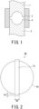
- Press molding is generally a method of inserting powder into a cavity between an upper die 1 and a lower die 2, as shown in FIG. 1 , then applying pressure thereto. During the press molding, there must be a gap between a tip 3 of the upper die 1 and a tip 4 of the lower die 2 to protect the dies. As a result, a spherical portion and a band-shaped portion are formed in the green compact.
- Patent Document 4 discloses a bearing ball material including a spherical portion and a band-shaped portion.
- reference character 5A denotes a ceramic ball material
- 6A denotes a spherical portion
- 7A denotes a band-shaped portion
- WA denotes the width of the band-shaped portion 7A
- HA denotes the height of the band-shaped portion 7A.
- a ceramic ball material 5A with a spherical portion 6A and a band-shaped portion 7A shown in FIG. 2 is polished to form a ceramic ball.
- the ceramic ball material 5A with the spherical portion 6A and the band-shaped portion 7A is sometimes referred to as a preliminary ball.
- the ceramic ball material 5A is polished to a mirror finish with a surface roughness Ra of 0.1 ⁇ m or less. The mirror finishing involves machining using surface plate.
- ceramic materials have excellent wear resistance but are prone to chipping when strong impacts are applied thereto because the materials are brittle. Curved surfaces easily release impact, while corners are prone to chipping due to impact. Therefore, when machining using surface plate is performed on the ceramic ball material 5A with the band-shaped portion 7A, both shoulders, which are the corners of the band-shaped portion 7A, selectively contact a surface plate, causing chipping.
- the present invention solves such problems and provides a ceramic ball material that suppresses damage to ceramic materials during machining using surface plate.
- a ceramic ball material according to the present embodiment includes a spherical portion, and a band-shaped portion formed over a circumference of a surface of the spherical portion.
- the band-shaped portion has a width in a range of 0.5 mm or more and 4.0 mm or less, both shoulders of which are provided with an R section having a radius of curvature of 0.02 mm or more.
- the ceramic ball material includes a spherical portion and a band-shaped portion formed over the circumference of the surface of the spherical portion.
- the band-shaped portion has a width in the range of 0.5 mm or more and 4.0 mm or less, both shoulders of which are provided with an R section having a radius of curvature of 0.02 mm or more.
- FIG. 3 is a schematic view of a ceramic ball material according to an embodiment.
- reference numeral 5 denotes the ceramic ball material according to the embodiment
- 6 denotes the spherical portion
- 7 denotes the band-shaped portion
- 8 denotes the R section
- 9 denotes the side periphery
- 10 denotes the outer periphery.
- Reference character r1 denotes the diameter of the outer periphery 10 of the band-shaped portion 7
- r2 denotes the diameter of the spherical portion 6.
- the diameter r2 of the spherical portion 6 is the length of a line segment passing through the center of the spherical portion 6 in the direction perpendicular to a plane formed by the circumference of the band-shaped portion 7.
- Reference character W denotes the width of the band-shaped portion 7
- H denotes the height of the band-shaped portion 7.
- the width W of the band-shaped portion 7 is sometimes simply referred to as "width W”.
- the height H of the band-shaped portion 7 is sometimes simply referred to as "height H”.
- FIG. 3 the sizes of the height H and width W of the band-shaped portion 7 with respect to the spherical portion 6 are illustrated for the purpose of description.
- the ceramic ball material 5 includes the spherical portion 6 and the band-shaped portion 7.
- the band-shaped portion 7 is formed over the circumference of the surface of the spherical portion 6.
- the circumference of the surface of the spherical portion 6 may be any one of multiple circumferences of the surface of the spherical portion 6.
- the surface of the spherical portion 6 being a quadric surface is sufficient. Therefore, the spherical portion 6 may be a true sphere or an ellipsoid.
- the band-shaped portion 7 is provided on the circumference of the spherical portion 6.
- the width W of the band-shaped portion 7 is, for example, the largest width of the band-shaped portion 7 but may be the average of widths at multiple positions.
- the height H of the band-shaped portion 7 is, for example, the maximum height of the band-shaped portion 7 but may be an average of heights at multiple positions.
- the width W of the band-shaped portion 7 is in the range of 0.5 mm or more and 4.0 mm or less. When the width W is in this range, damage to the die can be suppressed. In addition, the sphericity of the ceramic ball material 5 can be increased. As the sphericity of the ceramic ball material 5 increases, the machining time during the polishing process can be shortened.
- the sphericity of the ceramic ball material 5 decreases. As the sphericity decreases, the percentage of the spherical portion 6 decreases. As the sphericity of the ceramic ball material 5 decreases, a machining allowance during the polishing process increases, resulting in a longer machining process time.
- the width W is preferably 0.5 mm or more and 4 mm or less, and more preferably 0.8 mm or more and 3.5 mm or less.
- the band-shaped portion 7 comprises both shoulders extending over the circumference of the band-shaped portion 7, a side periphery 9 extending in the circumferential direction of the band-shaped portion 7, and an outer periphery 10 extending over the circumference of the band-shaped portion 7.
- Both shoulders of the band-shaped portion 7 are provided with an R section 8 having a radius of curvature of 0.02 mm or more.
- the R section 8 is present on both shoulders of the band-shaped portion 7.
- the R section is a rounded shape.
- Both shoulders of the band-shaped portion 7 are provided with the R section 8 having a radius of curvature of 0.02 mm or more, whereby surface contact with the grinding stone for polishing can be achieved.
- the contact with the grinding stone is a point contact.
- the angular shape refers to a shape in which both shoulders are at an angle of 90° or less in the cross-section of the band-shaped portion 7.
- the R section preferably has a radius of curvature of 0.02 mm or more, and more preferably 0.2 mm or more.
- the shape measurement is performed using an optical three-dimensional shape measuring device, Keyence VR-5000, with its analysis software.
- the measuring device may be one having a function equivalent thereto.
- a measurement area is an area where the height H of the band-shaped portion 7 is 1/4 or more and the entire width W is included.
- the screen is set at a magnification so as to include the measurement area.
- FIG. 4 shows an example of the R section 8 in the band-shaped portion 7.
- reference numerical 6 denotes the spherical portion
- 7 denotes the band-shaped portion
- 8 denotes the R section.
- FIG. 4 is a side view including a part of the band-shaped portion 7 that protrudes from the spherical portion 6.
- the method of measuring the radius of curvature of the R section 8 using the optical three-dimensional shape measuring device is described.
- the concept of the method of measuring the radius of curvature is described.
- the measurement itself is automatically calculated using the analysis software provided in the three-dimensional shape measuring device.
- the measurement of the radius of curvature of the R section 8 is performed using the function for measuring the radius of curvature of the three-dimensional shape measuring device by calculation using an imaginary circle C1 obtained by selecting three points p1, p2, and p3 in the R section 8 on one side.
- the point p1 is a boundary point between the side periphery 9 of the band-shaped portion 7 and the R section 8
- the point p3 is a boundary point between the R section 8 and the outer periphery 10 of the band-shaped portion 7
- the point p2 is a point between the point p1 and the point p3.
- the calculation result is taken as the radius of curvature of the R section 8.
- the radius of curvature of the R section 8 on the opposite side is calculated using an imaginary circle C2 obtained by selecting three points p4, p5, and p6.
- the point p6 is a boundary point between the side periphery 9 of the band-shaped portion 7 and the R section 8
- the point p4 is a boundary point between the R section 8 and the outer periphery 10 of the band-shaped portion 7
- the point p5 is a point between the point p6 and the point p4.
- the average of the calculation result of both shoulders is taken as the radius of curvature of the R section 8.
- the imaginary circles C1 and C2 may be ellipses as long as they pass through the respective points. In this regard, automatic calculation using the analysis software is preferred.
- Measuring again means reselecting the points p1 to p6, especially the points p2 and p5 in between, in the same field of view. In this case, some of the points p1 to p6 may be selected from the previous measurement point. Note that the method of selecting the points p1 to p6 is based on the preceding paragraph.
- the concave shape of the outer periphery 10 means that, in the band-shaped portion 7 along the circumference, the outer periphery 10 is more concave continuously along the circumference than both shoulders.
- the three-dimensional shape measuring device is also used to measure the radius of curvature of the concave shape of the outer periphery 10.
- the concept of the method of measuring the radius of curvature is described. The measurement of the radius of curvature of the concave shape itself is automatically performed by calculation using the analysis software provided in the three-dimensional shape measuring device.
- FIG. 5 shows an example of the concave shape of the band-shaped portion 7.
- FIG. 5 is a side view including a part of the band-shaped portion 7 that protrudes from the spherical portion 6.
- three points p7, p8, and p9 on the outer periphery 10 of the band-shaped portion 7 are selected to measure the curvature.
- three points p7, p8, and p9 are selected again to measure the curvature.
- FIG. 6 is a side view including a part of the band-shaped portion 7 that protrudes from the spherical portion 6.
- an imaginary circle C4 is first drawn at a position behind the band-shaped portion 7 that coincides with the spherical portion 6.
- extended imaginary lines L1 and L2 are drawn along the side periphery 9 of the band-shaped portion 7, and intersections between the extended imaginary lines L1 and L2 and the spherical portion 6 are defined as points p10 and p11, respectively.
- the points with the maximum height are extracted at both shoulders of the band-shaped portion 7 in the highest point extraction area and are defined as points p12 and p13.
- the shortest distances H1 and H2 from the points p12 and p13 are measured with respect to the line segment L3 connecting the points p10 and p11, respectively, and the average is defined as the height H of the band-shaped portion 7 (shown in FIG. 3 ).
- the shortest distances of the points p10 and p11 are each measured and defined as the width W of the band-shaped portion 7 (shown in FIG. 3 ).
- the diameters r1 and r2 are illustrated in FIG. 3 .
- the diameter r1 is the length extended from the center of the outer periphery 10 of the band-shaped portion 7 (the center between side peripheries 9 at both ends) toward the center of the outer periphery 10 on the opposite side, i.e., the diameter of the outer periphery 10.
- the diameter r1 is the diameter between the concave shape and the concave shape on the opposite side.
- the diameter r2 of the spherical portion 6 is, for example, the diameter of the spherical portion 6 that passes through the center of the spherical portion 6 in the direction orthogonal to the plane formed by the circumference of the band-shaped portion 7.
- the measurement of the diameters r1 and r2 is performed using a non-contact image dimension measuring device, Keyence IM-7000, or a device having a function equivalent thereto.
- the non-contact image dimension measuring device projects light onto an object from directly above to measure the dimension from its shadow.
- the measurement method is described below.
- the ceramic ball material 5 is placed on the stage. At this time, the ceramic ball material 5 is placed such that one of the radial directions of the band-shaped portion 7 is horizontally in the projection direction. When the band-shaped portion 7 is at an angle of 5° or more from the projection direction, the concave portion of the outer periphery 10 of the band-shaped portion 7 becomes invisible.
- the diameter r1 can be evaluated by setting up and measuring a measurement area so that the distance between the centers of the concave shape of the outer periphery 10 of the band-shaped portion 7 on the diagonal can be measured.
- the diameter r2 of the spherical portion 6 is measured as the length of a line segment passing through the center of the spherical portion 6 in the direction perpendicular to a plane formed by the circumference of the band-shaped portion 7.
- the outer periphery 10 of the band-shaped portion 7 is preferably flat or concave.
- the outer periphery 10 of the band-shaped portion 7 is preferably concave in shape.
- the concave shape indicates that the outer periphery 10 of the band-shaped portion 7 is concave with respect to both shoulders at both ends. If the outer periphery 10 is flat or concave, the R section 8 is easily formed on both shoulders of the band-shaped portion 7. On the other hand, if the outer periphery 10 of the band-shaped portion 7 is convex, the protrusion of that portion is likely to cause brittle fracture due to contact during machining using surface plate.
- the concave shape of the outer periphery 10 of the band-shaped portion 7 has a radius of curvature of 5 mm or more.
- the band-shaped portion 7 is ground.
- the upper limit of the radius of curvature of the concave shape of the outer periphery 10 of the band-shaped portion 7 is not particularly limited but is preferably 30 mm or less. If the radius of curvature of the concave shape becomes too large, it may be difficult to control the radius of curvature of the R section 8.
- the concave shape of the outer periphery 10 of the band-shaped portion 7 may contain minute irregularities on its surface.
- the convex portion (protrusion) is shown on the outer periphery 10 in Figs. 4 to 6 , the convex portion is not an essential configuration.
- the height of the convex position is lower than that of both shoulders.
- the concave shape of the outer periphery 10 of the band-shaped portion 7 preferably has a ratio of the radius of curvature/the width W of the band-shaped portion of 10 or less.
- the concave shape of the outer periphery 10 of the band-shaped portion 7 has a ratio of the radius of curvature/the width W of the band-shaped portion of more than 10, the curvature of the concave shape may be too large to control the radius of curvature of both shoulders of the band-shaped portion 7.
- the height H of the band-shaped portion 7 is preferably 2.5% or less with respect to the diameter r1 of the band-shaped portion 7, where (height H of band-shaped portion 7/ diameter r1 of band-shaped portion) ⁇ 100 ⁇ 2.5 is satisfied.
- the band-shaped portion 7 is removed by polishing.
- the height H of the band-shaped portion 7 becomes larger than the diameter r1 by 2.5%, the load of polishing increases. Furthermore, brittle fracture due to contact during machining using surface plate is likely to occur.
- the lower limit of the height H of the band-shaped portion 7 is preferably 0.1% or more with respect to the diameter r1 of the band-shaped portion 7.
- the height H of the band-shaped portion 7 is too small, densification around the band-shaped portion 7 may become difficult. For this reason, it is preferred that 0.1 ⁇ (the height H of the band-shaped portion 7/the diameter r1 of the band-shaped portion) ⁇ 100 ⁇ 2.5 is satisfied.
- the spherical portion 6 preferably has a diameter r2 of 0.5 mm or more. It is also preferred that the spherical portion 6 has an arbitrary diameter in the range of 8 mm or more and 70 mm or less, and the height H of the band-shaped portion is 1% or less of the diameter r2 of the spherical portion, which is indicated by (the height H of the band-shaped portion 7/the diameter r2 of the spherical portion 6) ⁇ 100 ⁇ 1.
- the ratio (r1/r2) of the diameter r1 of the band-shaped portion 7 to the diameter r2 of the spherical portion 6 is preferably in the range of 0.9 ⁇ r1/r2 ⁇ 1.1.
- the spherical portion 6 has an arbitrary diameter r2 of less than 0.5 mm, it becomes difficult to control the radius of curvature of the R section 8. For this reason, it is further preferred that the spherical portion 6 has a diameter r2 of 8 mm or more and 70 mm or less.
- 0.9 ⁇ r1/r2 ⁇ 1.1 indicates that the diameter r1 of the band-shaped portion 7 and the diameter r2 of the spherical portion 6 are approximated to each other.
- the ceramic ball material 5 preferably contains one or more of aluminum oxide (Al 2 O 3 ), silicon nitride (Si 3 N 4 ), boron nitride (BN), and zirconium oxide (ZrO 2 ) in an amount of 85% by mass or more.
- the ceramic ball material 5 is made of a ceramic sintered compact.
- the content in the ceramic sintered compact is 85% by mass or more of one or more of aluminum oxide, silicon nitride, boron nitride, and zirconium oxide.
- the ceramic sintered compact may contain 15% by mass or less of substances other than those mentioned above.
- the ceramic ball material 5 preferably contains 85 % by mass or more of silicon nitride.
- the aluminum oxide sintered compact, silicon nitride sintered compact, boron nitride sintered compact, zirconium oxide sintered compact, and Alusil sintered compact are used as bearing balls.
- the Alusil sintered compact is a sintered compact in which aluminum oxide and zirconium oxide are mixed.
- bearing balls made of silicon nitride sintered compact have the best wear resistance.
- aluminum oxide, zirconium oxide, and Alusil have a Vickers hardness of about 1,200 to 1,700 but a low fracture toughness value of about 3 to 6 MPa ⁇ m 1/2 .
- the silicon nitride sintered compact has a Vickers hardness of 1,400 to 1,800 and a high fracture toughness value of 5 to 10 MPa ⁇ m 1/2 .
- the silicon nitride sintered compact has both high toughness and Vickers hardness, which makes it excellent in wear resistance.
- the silicon nitride sintered compact has a structure mainly composed of ⁇ -type silicon nitride crystal particles.
- the ⁇ -type silicon nitride crystal particles have long and narrow shapes, in which a high toughness value is achieved by complex-intertwining of long and narrow crystal particles.
- the silicon nitride sintered compact has an aspect that the polishing efficiency is very poor due to its high mechanical strength, the polishing efficiency can be improved even in the ceramic ball material 5 made of a ceramic sintered compact with high strength such as silicon nitride sintered compact by providing the band-shaped portion 7 with an R section, as mentioned above.
- the manufacturing method is not particularly limited as long as the ceramic ball material 5 according to the embodiment satisfies the above configuration, but the following manufacturing method is a method for efficiently manufacturing the ceramic ball material 5.
- the method for manufacturing the ceramic ball material 5 is described with the case of using a silicon nitride sintered compact as an example.
- a sintering aid, additive, solvent, binder, and the like are added in appropriate quantities to silicon nitride as a raw material, then mixed, crushed, and granulated with a spray dryer. Through this process, the granulated powder is prepared as the raw material powder.
- the silicon nitride powder is preferably 85 % by mass or more.
- the additive is a plasticizer.
- the solvent is water or an organic solvent. Examples of the organic solvent include alcohol, ketone, and benzene.
- the binder is an organic substance.
- the amount of the binder added is in the range of 3 to 20 parts by mass when the total of the silicon nitride powder and the sintering aid powder is 100 parts by mass.
- press molding is performed using the granulated powder, examples of which include a molding method using the upper die 1 and the lower die 2 of the press molding apparatus shown in FIG. 1 .
- the spherical shape inside the upper die 1 and the lower die 2 becomes the spherical portion 6 of the ceramic ball material 5.
- the shape of the tip 3 of the upper die 1 and the tip 4 of the lower die 2 at the time of press molding and the amount of powder filled it is possible to adjust the width W and height H of the band-shaped portion 7 of the ceramic ball material 5.
- the diameter r1 and the diameter r2 can be adjusted.
- press molding is performed by setting the distance between the tip 3 of the upper die 1 and the tip 4 of the lower die 2 during the molding to 0.5 mm or more and 4 mm and then filling the gap with the granulated powder, whereby the width W of the band-shaped portion 7 can be controlled in the range of 0.5 mm or more and 4 mm or less.
- the green compact obtained by press molding has a spherical portion and a band-shaped portion.
- the spherical portion and band-shaped portion of the green compact correspond to the spherical portion 6 and band-shaped portion 7 of the above-mentioned ceramic ball material 5, respectively.
- Reference numeral r1-1 denotes the diameter of the band-shaped portion of the green compact
- r2-1 denotes the diameter of the spherical portion.
- the method of measuring the diameter r1-1 and diameter 2-1 of the green compact is the same as the method of measuring the diameters r1 and r2 of the above-mentioned ceramic ball material 5.
- 0.85 ⁇ (r1-1)/(r2-1) ⁇ 1.05 is satisfied.
- a sintered compact obtained through a sintering process discussed later can be made to satisfy 0.9 ⁇ r1/r2 ⁇ 1.1, which takes into account the shrinkage of the green compact due to the sintering process.
- isostatic pressing it is possible to uniformly apply compression to the granulated powder in the green compact, thereby making it possible to reduce the remaining crushed granulated powder in the green compact. By reducing the remaining crushed granulated powder, it is possible to control the shrinkage rate in the sintering process.
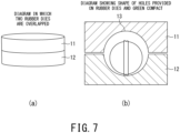
- FIG. 7 shows an example of a disk-shaped rubber die.
- reference numerals 11 and 12 denote disk-shaped rubber dies
- 13 denotes a space.
- FIG. 7(a) is a side view of a state in which the disk-shaped rubber dies 11 and 12 are overlapped.
- FIG. 7(b) is a cross-sectional view showing an example in which a green compact is placed in the space 13 within the disk-shaped rubber dies 11 and 12.
- the disk-shaped rubber dies 11 and 12 have hemispherical holes on both surfaces that are larger than the diameter r1 of the green compact by about 1% or more and 35% or less.
- the green compact is sealed in the space 13 surrounded by the rubber dies.
- a hydrostatic pressure higher than the pressure at the time of forming is applied to the rubber dies, thereby making it possible to uniformly apply compression to the green compact. This process can reduce the remaining crushed granulated powder.
- the rubber dies 11 and 12 be placed so that the band-shaped portion 7 of the green compact is perpendicular to the cylindrical direction of the rubber dies as shown in FIG. 7 .
- the rubber die 11 and the rubber die 12 to be used preferably have a Shore hardness Hs of 30 or more and 50 or less. With the hardness of the rubber dies in this range, the rubber dies can have a deformability that allows uniform contact between the surface of the green compact and the rubber dies. The rubber dies also have good durability.
- the R section 8 having a radius of curvature of 0.02 mm or more can be formed on both shoulders of the band-shaped portion 7 in the green compact.
- By adjusting the size ratio of the diameter r1-1 of the green compact to the space 13 it is possible to adjust the radius of curvature of the concave shape of the outer periphery 10 in the band-shaped portion 7 of the green compact and the height H of the band-shaped portion 7.
- a degreasing process is performed to degrease the green compact, in which the green compact is heated at a temperature equal to or higher than the decomposition temperature of organic components such as binder to evaporate the organic components.
- the degreasing process may be performed in a nitrogen atmosphere or an air atmosphere. Through the degreasing process, a degreased compact can be obtained.
- a sintering process is performed to sinter the degreased compact.
- the sintering process is preferably performed at a temperature of 1,600 degrees Celsius or more and 2,000 degrees Celsius or less in a nitrogen atmosphere.
- the sintered compact obtained by the sintering process may be subjected to a hot isostatic pressing (HIP) treatment. Through this step, the ceramic ball material 5 can be obtained.
- the ceramic ball material 5 is a ceramic sintered compact having a theoretical density of 98% or more.
- a method of polishing a completed ceramic ball material 5 may be applied. However, this method is not desirable because an additional polishing step is required. The manufacturing method described above is desirable.
- a ceramic ball can be manufactured by polishing the ceramic ball material 5.
- a typical polishing process for balls is a machining process using surface plate.
- the ceramic ball material 5 is inserted into a cavity between parallel upper and lower surface plates. By the movement of the polishing surface plates, the ceramic ball material 5 is processed into a perfect spherical shape.
- the surface roughness of bearing balls is specified in ASTM F2094.
- bearing balls are graded according to ASTM F2094 and polished to a surface roughness Ra according to that grade. As the grade increases, some bearing balls are polished to a mirror finish with a surface roughness Ra of 0.01 ⁇ m or less.
- ASTM refers to standards published by ASTM International, formerly known as American Society for Testing and Materials (ASTM).
- the ceramic ball material 5 according to the embodiment includes the R section 8 having a radius of curvature of 0.02 mm or more at both shoulders of the band-shaped portion 7.
- the R section 8 having a radius of curvature of 0.02 mm or more at both shoulders of the band-shaped portion 7.
- Sintering aids, additives, solvents, and binders were added to the raw ceramic powder, then mixed, crushed, and granulated with a spray dryer.
- Examples 1 to 3, 5, and 6 were silicon nitride sintered bodies
- Example 4 was an aluminum oxide sintered compact
- Example 7 was an Alusil sintered compact.
- the silicon nitride sintered bodies contained silicon nitride in an amount of 85% by mass or more.
- the aluminum oxide sintered compact contained aluminum oxide in an amount of 85% by mass or more.
- the Alusil sintered compact contained aluminum oxide and zirconium oxide in a total of 85 % by mass or more.
- the main component and a sintering aid were each 100 parts by mass, the amount of binder added was in the range of 3 to 20 parts by mass.
- press molding was performed using the granulated powder, which is die forming using the upper and lower dies of a press molding apparatus shown in FIG. 1 .
- the die forming was followed by isostatic pressing, which involved the use of a disk-shaped rubber die with a Shore hardness Hs of 30 or more and 50 or less.
- the isostatic pressing was performed with the disk-shaped rubber dies 11 and 12 having hemispherical holes on both surfaces that were larger than the diameter r1 of the green compact by 1% or more and 35% or less.
- the band-shaped portion of the green compact was placed perpendicular to the cylindrical direction of the rubber dies. In this state, a hydrostatic pressure higher than the pressure at the time of forming was applied in the process of isostatic pressing.
- a sintering process was performed at 1,600 to 2,000 degrees Celsius in a nitrogen atmosphere, and at atmospheric pressure, followed by HIP treatment at 1,600 to 2,000 degrees Celsius in a nitrogen atmosphere, and at a pressure of 200 MPa.
- Comparative Examples were prepared by adding 3 parts by mass of binder when the main component and the sintering aid were each 100 parts by mass. Isostatic pressing was not performed after the molding process.
- Example 1 is a ceramic ball material 5 for ceramic balls to be formed into 3/8 inches (9.525 mm) after the polishing process.
- Examples 2 and 4 are each a ceramic ball material 5 for ceramic balls of 5/16 inches (7.9375 mm).
- Examples 3 and 5 to 7 are each a ceramic ball material 5 for ceramic balls of 7/8 inches (22.225 mm).
- Comparative Examples 2 and 3 are each a ceramic ball material for ceramic balls of 5/16 inches (7.9375 mm), as in Examples 2 and 4.
- Comparative Example 1 is a ceramic ball material for ceramic balls of 7/8 inches (22.225 mm), as in Examples 3 and 5 to 7.
- the ceramic ball materials 5 of Examples 1 to 7 and ceramic ball materials of Comparative Examples 1 to 3 can all be used as bearing balls.
- Comparative Examples 1 and 3 each have the width W of the band-shaped portion outside the range.
- the band-shaped portion includes both shoulders having the radius of curvature of the R section outside the range.
- both shoulders of the band-shaped portion have an acute angle of less than 90°.
- the ceramic ball materials 5 of Examples and ceramic ball materials of Comparative Examples were evaluated with respect to polishing efficiency. The evaluation was conducted by examining how many batches the surface grinding stone could withstand when each ceramic ball material is machined using a #180 surface grinding stone and one batch is defined according to the size of the ceramic ball materials. The polishing process was performed so that the ceramic balls each had a surface roughness Ra of 0.01 ⁇ m.
- the rate of occurrence of defects such as chipping of the ceramic ball materials during the polishing process was also examined.
- the defect rate was calculated by visually inspecting one batch, and the rate of chipping was expressed as the percentage of material chipping defects (%), which was rounded off to two decimal places.
- Diameter variation a deviation of the diameter of the intended polished ceramic balls, was also examined.
- the diameter variation was defined as the difference between the minimum and maximum diameters when the entire circumference of the sphere was measured.
- the diameter variation was defined as the average of the results of measuring 10 ceramic balls arbitrarily selected in one batch. The results are shown in Table 2.
- Example 1 10,000 15 0.0 0.08
- Example 2 15,000 15 0.0 0.12
- Example 3 1,000 15 0.0 0.20
- Example 4 15,000 15 0.6 0.13
- Example 5 1,000 15 0.0 0.21
- Example 6 1,000 15 0.0 0.22
- the durability of the grindstone was improved in the ceramic ball material 5 according to Examples.
- the rate of defects of the ceramic ball materials 5 according to Examples declined.
- the deviation from the target diameter was also reduced in the ceramic ball material 5 according to Examples. Therefore, it is clear that the ceramic ball material 5 according to Examples has good polishing efficiency.
- the ceramic ball material 5 helps suppress damage to the ceramic material during machining using surface plate.
Landscapes
- Engineering & Computer Science (AREA)
- Chemical & Material Sciences (AREA)
- Ceramic Engineering (AREA)
- Manufacturing & Machinery (AREA)
- Materials Engineering (AREA)
- Structural Engineering (AREA)
- Organic Chemistry (AREA)
- Mechanical Engineering (AREA)
- General Engineering & Computer Science (AREA)
- Inorganic Chemistry (AREA)
- Composite Materials (AREA)
- Rolling Contact Bearings (AREA)
- Compositions Of Oxide Ceramics (AREA)
- Grinding And Polishing Of Tertiary Curved Surfaces And Surfaces With Complex Shapes (AREA)
- Finish Polishing, Edge Sharpening, And Grinding By Specific Grinding Devices (AREA)
- Ceramic Products (AREA)
- Press-Shaping Or Shaping Using Conveyers (AREA)
Abstract
Description
- Embodiments discussed later relate to a ceramic ball material, a method for manufacturing a ceramic ball, and a ceramic ball.
- Various ceramic materials have properties such as high hardness, insulation, and wear resistance. In particular, fine ceramics with enhanced purity and uniform particle size exhibit properties applicable in various fields of, for example, capacitors, actuator materials, and refractories. Products that take advantage of the wear resistance and insulation mentioned above are bearing balls, which are made of materials such as aluminum oxide, silicon nitride, and zirconium oxide. For example,
Japanese Patent Laid-Open No. H06-48813 Japanese Patent No. 2764589 Japanese Patent Laid-Open No. S60-18620 - In the process of manufacturing these materials for bearing balls, a method of sintering a green compact is employed. Press molding using dies is adopted as the molding method. Press molding is generally a method of inserting powder into a cavity between an upper die 1 and a
lower die 2, as shown inFIG. 1 , then applying pressure thereto. During the press molding, there must be a gap between atip 3 of the upper die 1 and atip 4 of thelower die 2 to protect the dies. As a result, a spherical portion and a band-shaped portion are formed in the green compact. For example,Japanese Patent No. 4761613 FIG. 2 shows a conventional ceramic ball material. InFIG. 2 ,reference character 5A denotes a ceramic ball material, 6A denotes a spherical portion, 7A denotes a band-shaped portion, WA denotes the width of the band-shaped portion 7A, and HA denotes the height of the band-shaped portion 7A. -
- Patent Document 1:
Japanese Patent Laid-Open No. H06-48813 - Patent Document 2:
Japanese Patent No. 2764589 - Patent Document 3:
Japanese Patent Laid-Open No. S60-18620 - Patent Document 4:
Japanese Patent No. 4761613 - A
ceramic ball material 5A with aspherical portion 6A and a band-shaped portion 7A shown inFIG. 2 is polished to form a ceramic ball. Theceramic ball material 5A with thespherical portion 6A and the band-shaped portion 7A is sometimes referred to as a preliminary ball. For example, theceramic ball material 5A is polished to a mirror finish with a surface roughness Ra of 0.1 µm or less. The mirror finishing involves machining using surface plate. - In general, ceramic materials have excellent wear resistance but are prone to chipping when strong impacts are applied thereto because the materials are brittle. Curved surfaces easily release impact, while corners are prone to chipping due to impact. Therefore, when machining using surface plate is performed on the
ceramic ball material 5A with the band-shaped portion 7A, both shoulders, which are the corners of the band-shaped portion 7A, selectively contact a surface plate, causing chipping. - The present invention solves such problems and provides a ceramic ball material that suppresses damage to ceramic materials during machining using surface plate.
- A ceramic ball material according to the present embodiment includes a spherical portion, and a band-shaped portion formed over a circumference of a surface of the spherical portion. The band-shaped portion has a width in a range of 0.5 mm or more and 4.0 mm or less, both shoulders of which are provided with an R section having a radius of curvature of 0.02 mm or more.
-
- [
FIG. 1] FIG. 1 is a cross-sectional view showing an example of a general die press molding apparatus. - [
FIG. 2] FIG. 2 is an external view showing an example of a conventional ceramic ball material. - [
FIG. 3] FIG. 3 is an external view showing an example of the ceramic ball material according to the embodiment. - [
FIG. 4] FIG. 4 is an external view showing an example of a band-shaped portion. - [
FIG. 5] FIG. 5 is an external view showing another example of the band-shaped portion. - [
FIG. 6] FIG. 6 is an external view showing the other example of the band-shaped portion. - [
FIG. 7] FIG. 7 is a diagram showing an example of die press molding for molding the ceramic ball material according to the embodiment. - Hereinafter, embodiments of a ceramic ball material, a method for manufacturing a ceramic ball, and a ceramic ball are described in detail with reference to the drawings.
- The ceramic ball material according to an embodiment includes a spherical portion and a band-shaped portion formed over the circumference of the surface of the spherical portion. The band-shaped portion has a width in the range of 0.5 mm or more and 4.0 mm or less, both shoulders of which are provided with an R section having a radius of curvature of 0.02 mm or more.
-
FIG. 3 is a schematic view of a ceramic ball material according to an embodiment. InFIG. 3 ,reference numeral 5 denotes the ceramic ball material according to the embodiment, 6 denotes the spherical portion, 7 denotes the band-shaped portion, 8 denotes the R section, 9 denotes the side periphery, and 10 denotes the outer periphery. Reference character r1 denotes the diameter of theouter periphery 10 of the band-shaped portion 7, and r2 denotes the diameter of thespherical portion 6. For example, the diameter r2 of thespherical portion 6 is the length of a line segment passing through the center of thespherical portion 6 in the direction perpendicular to a plane formed by the circumference of the band-shaped portion 7. Reference character W denotes the width of the band-shaped portion 7, and H denotes the height of the band-shaped portion 7. The width W of the band-shaped portion 7 is sometimes simply referred to as "width W". The height H of the band-shaped portion 7 is sometimes simply referred to as "height H". InFIG. 3 , the sizes of the height H and width W of the band-shaped portion 7 with respect to thespherical portion 6 are illustrated for the purpose of description. - The
ceramic ball material 5 includes thespherical portion 6 and the band-shaped portion 7. The band-shaped portion 7 is formed over the circumference of the surface of thespherical portion 6. The circumference of the surface of thespherical portion 6 may be any one of multiple circumferences of the surface of thespherical portion 6. The surface of thespherical portion 6 being a quadric surface is sufficient. Therefore, thespherical portion 6 may be a true sphere or an ellipsoid. The band-shaped portion 7 is provided on the circumference of thespherical portion 6. The width W of the band-shaped portion 7 is, for example, the largest width of the band-shaped portion 7 but may be the average of widths at multiple positions. The height H of the band-shaped portion 7 is, for example, the maximum height of the band-shaped portion 7 but may be an average of heights at multiple positions. - The width W of the band-
shaped portion 7 is in the range of 0.5 mm or more and 4.0 mm or less. When the width W is in this range, damage to the die can be suppressed. In addition, the sphericity of theceramic ball material 5 can be increased. As the sphericity of theceramic ball material 5 increases, the machining time during the polishing process can be shortened. - When the width W is less than 0.5 mm, compression forces on the
tip 3 of the upper die 1 andtip 4 of thelower die 2 shown inFIG. 1 become very large, which may cause damage to the dies. Further, density heterogeneity may occur around the band-shaped portion of the resulting sintered compact. If the density is uneven, the sintered compact is prone to defects, which may adversely affect the wear resistance. - When the width W exceeds 4.0 mm, the sphericity of the
ceramic ball material 5 decreases. As the sphericity decreases, the percentage of thespherical portion 6 decreases. As the sphericity of theceramic ball material 5 decreases, a machining allowance during the polishing process increases, resulting in a longer machining process time. - Thus, the width W is preferably 0.5 mm or more and 4 mm or less, and more preferably 0.8 mm or more and 3.5 mm or less.
- The band-shaped
portion 7 comprises both shoulders extending over the circumference of the band-shapedportion 7, aside periphery 9 extending in the circumferential direction of the band-shapedportion 7, and anouter periphery 10 extending over the circumference of the band-shapedportion 7. Both shoulders of the band-shapedportion 7 are provided with anR section 8 having a radius of curvature of 0.02 mm or more. TheR section 8 is present on both shoulders of the band-shapedportion 7. The R section is a rounded shape. Both shoulders of the band-shapedportion 7 are provided with theR section 8 having a radius of curvature of 0.02 mm or more, whereby surface contact with the grinding stone for polishing can be achieved. When theR section 8 has a radius of curvature of less than 0.02 mm or an angular shape, the contact with the grinding stone is a point contact. The angular shape refers to a shape in which both shoulders are at an angle of 90° or less in the cross-section of the band-shapedportion 7. When it comes to point contact, brittle fracture is likely to occur in contact between theceramic ball material 5 and the grinding stone. In particular, brittle fracture is more likely to occur in contact with the surface plate during machining using surface plate. Thus, the R section preferably has a radius of curvature of 0.02 mm or more, and more preferably 0.2 mm or more. - Here, a method of measuring the radius of curvature of the
R section 8 of the band-shapedportion 7 in theceramic ball material 5 is described. - The shape measurement is performed using an optical three-dimensional shape measuring device, Keyence VR-5000, with its analysis software. The measuring device may be one having a function equivalent thereto.
- A measurement area is an area where the height H of the band-shaped
portion 7 is 1/4 or more and the entire width W is included. The screen is set at a magnification so as to include the measurement area.FIG. 4 shows an example of theR section 8 in the band-shapedportion 7. InFIG. 4 , reference numerical 6 denotes the spherical portion, 7 denotes the band-shaped portion, and 8 denotes the R section.FIG. 4 is a side view including a part of the band-shapedportion 7 that protrudes from thespherical portion 6. - The method of measuring the radius of curvature of the
R section 8 using the optical three-dimensional shape measuring device is described. Hereinafter, the concept of the method of measuring the radius of curvature is described. The measurement itself is automatically calculated using the analysis software provided in the three-dimensional shape measuring device. - The measurement of the radius of curvature of the
R section 8 is performed using the function for measuring the radius of curvature of the three-dimensional shape measuring device by calculation using an imaginary circle C1 obtained by selecting three points p1, p2, and p3 in theR section 8 on one side. In this case, the point p1 is a boundary point between theside periphery 9 of the band-shapedportion 7 and theR section 8; the point p3 is a boundary point between theR section 8 and theouter periphery 10 of the band-shapedportion 7; and the point p2 is a point between the point p1 and the point p3. The calculation result is taken as the radius of curvature of theR section 8. Similarly, the radius of curvature of theR section 8 on the opposite side is calculated using an imaginary circle C2 obtained by selecting three points p4, p5, and p6. In this case, the point p6 is a boundary point between theside periphery 9 of the band-shapedportion 7 and theR section 8; the point p4 is a boundary point between theR section 8 and theouter periphery 10 of the band-shapedportion 7; and the point p5 is a point between the point p6 and the point p4. The average of the calculation result of both shoulders is taken as the radius of curvature of theR section 8. The imaginary circles C1 and C2 may be ellipses as long as they pass through the respective points. In this regard, automatic calculation using the analysis software is preferred. - When the imaginary circles C1 and C2 both do not pass through the points p1 to p6, it is determined that the radius of curvature cannot be measured accurately. Similarly, if there exist points separated by 10 µm or more when an actual curve formed by points p1 to p6 is compared with the curve along the relevant points formed by the imaginary circles C1 and C2, it is determined that the radius of curvature cannot be measured accurately. When it is determined that the radius of curvature cannot be measured accurately as described above, points p1 to p6, especially points p2 and p5 in-between, are selected again to measure the radius of curvature. Measuring again means reselecting the points p1 to p6, especially the points p2 and p5 in between, in the same field of view. In this case, some of the points p1 to p6 may be selected from the previous measurement point. Note that the method of selecting the points p1 to p6 is based on the preceding paragraph.
- In addition, a method of measuring the radius of curvature of the concave shape of the
outer periphery 10 sandwiched between the shoulder portions of the band-shapedportion 7, which will be discussed later, is also described. Here, the concave shape of theouter periphery 10 means that, in the band-shapedportion 7 along the circumference, theouter periphery 10 is more concave continuously along the circumference than both shoulders. The three-dimensional shape measuring device is also used to measure the radius of curvature of the concave shape of theouter periphery 10. Hereinafter, the concept of the method of measuring the radius of curvature is described. The measurement of the radius of curvature of the concave shape itself is automatically performed by calculation using the analysis software provided in the three-dimensional shape measuring device. -
FIG. 5 shows an example of the concave shape of the band-shapedportion 7.FIG. 5 is a side view including a part of the band-shapedportion 7 that protrudes from thespherical portion 6. As shown inFIG. 5 , three points p7, p8, and p9 on theouter periphery 10 of the band-shapedportion 7 are selected to measure the curvature. At this point, if there exist points separated by 10 µm or more when an actual curve formed by the points p7 to p9 is compared with a curve along the relevant points p7 to p9 on an imaginary circle C3, it is determined that the radius of curvature cannot be measured accurately. In this case, three points p7, p8, and p9 are selected again to measure the curvature. - The case of measuring the height H of the band-shaped
portion 7 is also described.FIG. 6 is a side view including a part of the band-shapedportion 7 that protrudes from thespherical portion 6. As shown inFIG. 6 , an imaginary circle C4 is first drawn at a position behind the band-shapedportion 7 that coincides with thespherical portion 6. Next, extended imaginary lines L1 and L2 are drawn along theside periphery 9 of the band-shapedportion 7, and intersections between the extended imaginary lines L1 and L2 and thespherical portion 6 are defined as points p10 and p11, respectively. If there exist points separated by 5 µm or more when theside periphery 9 of the band-shapedportion 7 and the extended imaginary lines L1 and L2 are compared, it is determined that the extended imaginary lines have not been drawn accurately, so the lines are redrawn. The points with the maximum height are extracted at both shoulders of the band-shapedportion 7 in the highest point extraction area and are defined as points p12 and p13. The shortest distances H1 and H2 from the points p12 and p13 are measured with respect to the line segment L3 connecting the points p10 and p11, respectively, and the average is defined as the height H of the band-shaped portion 7 (shown inFIG. 3 ). The shortest distances of the points p10 and p11 are each measured and defined as the width W of the band-shaped portion 7 (shown inFIG. 3 ). - In addition, a method of measuring the diameter r1 of the band-shaped
portion 7 and the diameter r2 of thespherical portion 6, which will be discussed later, is described. The diameters r1 and r2 are illustrated inFIG. 3 . The diameter r1 is the length extended from the center of theouter periphery 10 of the band-shaped portion 7 (the center betweenside peripheries 9 at both ends) toward the center of theouter periphery 10 on the opposite side, i.e., the diameter of theouter periphery 10. When theouter periphery 10 of the band-shapedportion 7 has a concave shape, the diameter r1 is the diameter between the concave shape and the concave shape on the opposite side. The diameter r2 of thespherical portion 6 is, for example, the diameter of thespherical portion 6 that passes through the center of thespherical portion 6 in the direction orthogonal to the plane formed by the circumference of the band-shapedportion 7. - The measurement of the diameters r1 and r2 is performed using a non-contact image dimension measuring device, Keyence IM-7000, or a device having a function equivalent thereto. The non-contact image dimension measuring device projects light onto an object from directly above to measure the dimension from its shadow. The measurement method is described below. The
ceramic ball material 5 is placed on the stage. At this time, theceramic ball material 5 is placed such that one of the radial directions of the band-shapedportion 7 is horizontally in the projection direction. When the band-shapedportion 7 is at an angle of 5° or more from the projection direction, the concave portion of theouter periphery 10 of the band-shapedportion 7 becomes invisible. The diameter r1 can be evaluated by setting up and measuring a measurement area so that the distance between the centers of the concave shape of theouter periphery 10 of the band-shapedportion 7 on the diagonal can be measured. The diameter r2 of thespherical portion 6 is measured as the length of a line segment passing through the center of thespherical portion 6 in the direction perpendicular to a plane formed by the circumference of the band-shapedportion 7. - The
outer periphery 10 of the band-shapedportion 7 is preferably flat or concave. Theouter periphery 10 of the band-shapedportion 7 is preferably concave in shape. The concave shape indicates that theouter periphery 10 of the band-shapedportion 7 is concave with respect to both shoulders at both ends. If theouter periphery 10 is flat or concave, theR section 8 is easily formed on both shoulders of the band-shapedportion 7. On the other hand, if theouter periphery 10 of the band-shapedportion 7 is convex, the protrusion of that portion is likely to cause brittle fracture due to contact during machining using surface plate. - The concave shape of the
outer periphery 10 of the band-shapedportion 7 has a radius of curvature of 5 mm or more. When theceramic ball material 5 is polished into a ceramic ball, the band-shapedportion 7 is ground. By increasing the radius of curvature of the concave shape of theouter periphery 10, the volume of the band-shapedportion 7 to be ground can be reduced, thereby making it possible to reduce the polishing allowance. The upper limit of the radius of curvature of the concave shape of theouter periphery 10 of the band-shapedportion 7 is not particularly limited but is preferably 30 mm or less. If the radius of curvature of the concave shape becomes too large, it may be difficult to control the radius of curvature of theR section 8. The concave shape of theouter periphery 10 of the band-shapedportion 7 may contain minute irregularities on its surface. Although the convex portion (protrusion) is shown on theouter periphery 10 inFigs. 4 to 6 , the convex portion is not an essential configuration. In addition, when the convex portion (protrusion) is present on theouter periphery 10, the height of the convex position is lower than that of both shoulders. - The concave shape of the
outer periphery 10 of the band-shapedportion 7 preferably has a ratio of the radius of curvature/the width W of the band-shaped portion of 10 or less. When the concave shape of theouter periphery 10 of the band-shapedportion 7 has a ratio of the radius of curvature/the width W of the band-shaped portion of more than 10, the curvature of the concave shape may be too large to control the radius of curvature of both shoulders of the band-shapedportion 7. - The height H of the band-shaped
portion 7 is preferably 2.5% or less with respect to the diameter r1 of the band-shapedportion 7, where (height H of band-shapedportion 7/ diameter r1 of band-shaped portion) × 100 ≤ 2.5 is satisfied. As mentioned above, the band-shapedportion 7 is removed by polishing. When the height H of the band-shapedportion 7 becomes larger than the diameter r1 by 2.5%, the load of polishing increases. Furthermore, brittle fracture due to contact during machining using surface plate is likely to occur. Note that the lower limit of the height H of the band-shapedportion 7 is preferably 0.1% or more with respect to the diameter r1 of the band-shapedportion 7. If the height H of the band-shapedportion 7 is too small, densification around the band-shapedportion 7 may become difficult. For this reason, it is preferred that 0.1 ≤ (the height H of the band-shapedportion 7/the diameter r1 of the band-shaped portion) × 100 ≤ 2.5 is satisfied. - The
spherical portion 6 preferably has a diameter r2 of 0.5 mm or more. It is also preferred that thespherical portion 6 has an arbitrary diameter in the range of 8 mm or more and 70 mm or less, and the height H of the band-shaped portion is 1% or less of the diameter r2 of the spherical portion, which is indicated by (the height H of the band-shapedportion 7/the diameter r2 of the spherical portion 6) × 100 ≤ 1. - In addition, the ratio (r1/r2) of the diameter r1 of the band-shaped
portion 7 to the diameter r2 of thespherical portion 6 is preferably in the range of 0.9 ≤ r1/r2 ≤ 1.1. - When the
spherical portion 6 has an arbitrary diameter r2 of less than 0.5 mm, it becomes difficult to control the radius of curvature of theR section 8. For this reason, it is further preferred that thespherical portion 6 has a diameter r2 of 8 mm or more and 70 mm or less. - Moreover, 0.9 ≤ r1/r2 ≤ 1.1 indicates that the diameter r1 of the band-shaped
portion 7 and the diameter r2 of thespherical portion 6 are approximated to each other. Thus, it is possible to suppress stress concentration by making the initial contact with the surface plate for machining uniform so as to suppress damage during machining. - The
ceramic ball material 5 preferably contains one or more of aluminum oxide (Al2O3), silicon nitride (Si3N4), boron nitride (BN), and zirconium oxide (ZrO2) in an amount of 85% by mass or more. Theceramic ball material 5 is made of a ceramic sintered compact. The content in the ceramic sintered compact is 85% by mass or more of one or more of aluminum oxide, silicon nitride, boron nitride, and zirconium oxide. In other words, the ceramic sintered compact may contain 15% by mass or less of substances other than those mentioned above. Theceramic ball material 5 preferably contains 85 % by mass or more of silicon nitride. - For example, the aluminum oxide sintered compact, silicon nitride sintered compact, boron nitride sintered compact, zirconium oxide sintered compact, and Alusil sintered compact are used as bearing balls. The Alusil sintered compact is a sintered compact in which aluminum oxide and zirconium oxide are mixed. Among them, bearing balls made of silicon nitride sintered compact have the best wear resistance. For instance, aluminum oxide, zirconium oxide, and Alusil have a Vickers hardness of about 1,200 to 1,700 but a low fracture toughness value of about 3 to 6 MPa·m1/2. On the other hand, the silicon nitride sintered compact has a Vickers hardness of 1,400 to 1,800 and a high fracture toughness value of 5 to 10 MPa·m1/2. The silicon nitride sintered compact has both high toughness and Vickers hardness, which makes it excellent in wear resistance. The silicon nitride sintered compact has a structure mainly composed of β-type silicon nitride crystal particles. The β-type silicon nitride crystal particles have long and narrow shapes, in which a high toughness value is achieved by complex-intertwining of long and narrow crystal particles. Although the silicon nitride sintered compact has an aspect that the polishing efficiency is very poor due to its high mechanical strength, the polishing efficiency can be improved even in the
ceramic ball material 5 made of a ceramic sintered compact with high strength such as silicon nitride sintered compact by providing the band-shapedportion 7 with an R section, as mentioned above. - Next, a method for manufacturing the
ceramic ball material 5 is described. The manufacturing method is not particularly limited as long as theceramic ball material 5 according to the embodiment satisfies the above configuration, but the following manufacturing method is a method for efficiently manufacturing theceramic ball material 5. The method for manufacturing theceramic ball material 5 is described with the case of using a silicon nitride sintered compact as an example. - First, a sintering aid, additive, solvent, binder, and the like are added in appropriate quantities to silicon nitride as a raw material, then mixed, crushed, and granulated with a spray dryer. Through this process, the granulated powder is prepared as the raw material powder. When the total of the silicon nitride powder and the sintering aid powder is 100% by mass, the silicon nitride powder is preferably 85 % by mass or more. The additive is a plasticizer. The solvent is water or an organic solvent. Examples of the organic solvent include alcohol, ketone, and benzene. The binder is an organic substance. The amount of the binder added is in the range of 3 to 20 parts by mass when the total of the silicon nitride powder and the sintering aid powder is 100 parts by mass. By adjusting the amount of the binder, it becomes easy to impart a concave shape to the
outer periphery 10 of the band-shapedportion 7 in a process discussed later. - Next, press molding is performed using the granulated powder, examples of which include a molding method using the upper die 1 and the
lower die 2 of the press molding apparatus shown inFIG. 1 . The spherical shape inside the upper die 1 and thelower die 2 becomes thespherical portion 6 of theceramic ball material 5. By adjusting the shape of thetip 3 of the upper die 1 and thetip 4 of thelower die 2 at the time of press molding and the amount of powder filled, it is possible to adjust the width W and height H of the band-shapedportion 7 of theceramic ball material 5. Similarly, the diameter r1 and the diameter r2 can be adjusted. For example, press molding is performed by setting the distance between thetip 3 of the upper die 1 and thetip 4 of thelower die 2 during the molding to 0.5 mm or more and 4 mm and then filling the gap with the granulated powder, whereby the width W of the band-shapedportion 7 can be controlled in the range of 0.5 mm or more and 4 mm or less. - The green compact obtained by press molding has a spherical portion and a band-shaped portion. The spherical portion and band-shaped portion of the green compact correspond to the
spherical portion 6 and band-shapedportion 7 of the above-mentionedceramic ball material 5, respectively. Reference numeral r1-1 denotes the diameter of the band-shaped portion of the green compact, and r2-1 denotes the diameter of the spherical portion. The method of measuring the diameter r1-1 and diameter 2-1 of the green compact is the same as the method of measuring the diameters r1 and r2 of the above-mentionedceramic ball material 5. In the stage of the green compact, it is preferred that 0.85 ≤ (r1-1)/(r2-1) ≤ 1.05 is satisfied. Within this range, a sintered compact obtained through a sintering process discussed later can be made to satisfy 0.9 ≤ r1/r2 ≤ 1.1, which takes into account the shrinkage of the green compact due to the sintering process. - In addition, it is also preferable to perform isostatic pressing on the green compact. Through isostatic pressing, it is possible to uniformly apply compression to the granulated powder in the green compact, thereby making it possible to reduce the remaining crushed granulated powder in the green compact. By reducing the remaining crushed granulated powder, it is possible to control the shrinkage rate in the sintering process.
- The isostatic pressing method using rubber dies is described as an example of isostatic pressing.
FIG. 7 shows an example of a disk-shaped rubber die. InFIG. 7 ,reference numerals FIG. 7(a) is a side view of a state in which the disk-shaped rubber dies 11 and 12 are overlapped.FIG. 7(b) is a cross-sectional view showing an example in which a green compact is placed in thespace 13 within the disk-shaped rubber dies 11 and 12. - The disk-shaped rubber dies 11 and 12 have hemispherical holes on both surfaces that are larger than the diameter r1 of the green compact by about 1% or more and 35% or less. By placing the green compact in the holes and overlapping the rubber dies, the green compact is sealed in the
space 13 surrounded by the rubber dies. A hydrostatic pressure higher than the pressure at the time of forming is applied to the rubber dies, thereby making it possible to uniformly apply compression to the green compact. This process can reduce the remaining crushed granulated powder. It is preferred that the rubber dies 11 and 12 be placed so that the band-shapedportion 7 of the green compact is perpendicular to the cylindrical direction of the rubber dies as shown inFIG. 7 . The rubber die 11 and the rubber die 12 to be used preferably have a Shore hardness Hs of 30 or more and 50 or less. With the hardness of the rubber dies in this range, the rubber dies can have a deformability that allows uniform contact between the surface of the green compact and the rubber dies. The rubber dies also have good durability. Through this process, theR section 8 having a radius of curvature of 0.02 mm or more can be formed on both shoulders of the band-shapedportion 7 in the green compact. By adjusting the size ratio of the diameter r1-1 of the green compact to thespace 13, it is possible to adjust the radius of curvature of the concave shape of theouter periphery 10 in the band-shapedportion 7 of the green compact and the height H of the band-shapedportion 7. - Subsequently, a degreasing process is performed to degrease the green compact, in which the green compact is heated at a temperature equal to or higher than the decomposition temperature of organic components such as binder to evaporate the organic components. The degreasing process may be performed in a nitrogen atmosphere or an air atmosphere. Through the degreasing process, a degreased compact can be obtained.
- Next, a sintering process is performed to sinter the degreased compact. The sintering process is preferably performed at a temperature of 1,600 degrees Celsius or more and 2,000 degrees Celsius or less in a nitrogen atmosphere. The pressure during sintering is preferably in the range of atmospheric pressure or more and 300 MPa or less. Note that the atmospheric pressure is 0.10133 MPa (= 1 atm). The sintered compact obtained by the sintering process may be subjected to a hot isostatic pressing (HIP) treatment. Through this step, the
ceramic ball material 5 can be obtained. Theceramic ball material 5 is a ceramic sintered compact having a theoretical density of 98% or more. - With respect to the adjustment of the radius of curvature of the
R section 8 of both shoulders in the band-shapedportion 7, a method of polishing a completedceramic ball material 5 may be applied. However, this method is not desirable because an additional polishing step is required. The manufacturing method described above is desirable. - A ceramic ball can be manufactured by polishing the
ceramic ball material 5. A typical polishing process for balls is a machining process using surface plate. For example, theceramic ball material 5 is inserted into a cavity between parallel upper and lower surface plates. By the movement of the polishing surface plates, theceramic ball material 5 is processed into a perfect spherical shape. The surface roughness of bearing balls is specified in ASTM F2094. Depending on the application, bearing balls are graded according to ASTM F2094 and polished to a surface roughness Ra according to that grade. As the grade increases, some bearing balls are polished to a mirror finish with a surface roughness Ra of 0.01 µm or less. Note that ASTM refers to standards published by ASTM International, formerly known as American Society for Testing and Materials (ASTM). - The
ceramic ball material 5 according to the embodiment includes theR section 8 having a radius of curvature of 0.02 mm or more at both shoulders of the band-shapedportion 7. As a result, surface contact with a grinding stone of, for example, a lapping plate can be achieved, thereby preventing theceramic ball material 5 from being damaged in the polishing process. In addition, the durability of the lapping plate can be improved. By controlling the shape and the like of the band-shapedportion 7, it is possible to improve the workability while reducing the polishing allowance. - Sintering aids, additives, solvents, and binders were added to the raw ceramic powder, then mixed, crushed, and granulated with a spray dryer. Examples 1 to 3, 5, and 6 were silicon nitride sintered bodies, Example 4 was an aluminum oxide sintered compact, and Example 7 was an Alusil sintered compact. The silicon nitride sintered bodies contained silicon nitride in an amount of 85% by mass or more. The aluminum oxide sintered compact contained aluminum oxide in an amount of 85% by mass or more. In addition, the Alusil sintered compact contained aluminum oxide and zirconium oxide in a total of 85 % by mass or more. When the main component and a sintering aid were each 100 parts by mass, the amount of binder added was in the range of 3 to 20 parts by mass.
- Next, press molding was performed using the granulated powder, which is die forming using the upper and lower dies of a press molding apparatus shown in
FIG. 1 . The die forming was followed by isostatic pressing, which involved the use of a disk-shaped rubber die with a Shore hardness Hs of 30 or more and 50 or less. The isostatic pressing was performed with the disk-shaped rubber dies 11 and 12 having hemispherical holes on both surfaces that were larger than the diameter r1 of the green compact by 1% or more and 35% or less. The band-shaped portion of the green compact was placed perpendicular to the cylindrical direction of the rubber dies. In this state, a hydrostatic pressure higher than the pressure at the time of forming was applied in the process of isostatic pressing. - Next, a sintering process was performed at 1,600 to 2,000 degrees Celsius in a nitrogen atmosphere, and at atmospheric pressure, followed by HIP treatment at 1,600 to 2,000 degrees Celsius in a nitrogen atmosphere, and at a pressure of 200 MPa.
- Through this process, ceramic ball materials according to Examples were produced. Comparative Examples were prepared by adding 3 parts by mass of binder when the main component and the sintering aid were each 100 parts by mass. Isostatic pressing was not performed after the molding process.
- The shape of the
ceramic ball materials 5 according to Examples and the shape of ceramic ball materials according to Comparative Examples were each measured by methods as described above. Note that H/r1 (%) means (H/r1) × 100 (%). The results are shown in Table 1.[Table 1] Ceramic Ball Material Type of Ceramic Sintered Compact Band-Shaped Portion Width W [mm] Heigh -t H [mm] H/r1 [%] Radius of Curvature of R Section [mm] Radius of Curvature of Outer Periphery [mm] Example 1 Si3N4 1.5 0.1 1.0 0.30 10 Example 2 Si3N4 0.8 0.12 1.4 0.10 7 Example 3 Si3N4 3.0 0.20 0.9 0.30 25 Example 4 Al2O3 3.5 0.15 1.7 0.05 0 Example 5 Si3N4 3.2 0.18 0.7 0.25 18 Example 6 Si3N4 3.5 0.55 2.3 0.35 20 Example 7 Alusil 2.5 0.12 0.5 0.08 10 Comparative Example 1 Si3N4 6.0 0.2 0.9 0.10 20 Comparative Example 2 Al2O3 1.0 0.1 1.1 - (sharp angle) 7 Comparative Example 3 Al2O3 0.3 0.3 3.4 0.08 4 Ceramic Ball Material Diameter After Polishing [inch] Diameter r1 [mm] Diameter r2 [mm] r1/r2 Example 1 10.3 10.5 0.98 3/8" Example 2 9.0 9.2 0.98 5/16" Example 3 23.8 23.8 1.00 7/8" Example 4 8.7 9.5 0.92 5/16" Example 5 24.5 23.6 1.05 7/8" Example 6 23.7 23.2 1.02 7/8" Example 7 24.2 24.0 1.01 7/8" Comparative Example 1 24.1 23.0 1.05 7/8" Comparative Example 2 8.5 9.6 0.89 5/16" Comparative Example 3 9.0 8.9 1.01 5/16" - Example 1 is a
ceramic ball material 5 for ceramic balls to be formed into 3/8 inches (9.525 mm) after the polishing process. Examples 2 and 4 are each aceramic ball material 5 for ceramic balls of 5/16 inches (7.9375 mm). Examples 3 and 5 to 7 are each aceramic ball material 5 for ceramic balls of 7/8 inches (22.225 mm). Comparative Examples 2 and 3 are each a ceramic ball material for ceramic balls of 5/16 inches (7.9375 mm), as in Examples 2 and 4. Comparative Example 1 is a ceramic ball material for ceramic balls of 7/8 inches (22.225 mm), as in Examples 3 and 5 to 7. Theceramic ball materials 5 of Examples 1 to 7 and ceramic ball materials of Comparative Examples 1 to 3 can all be used as bearing balls. - Comparative Examples 1 and 3 each have the width W of the band-shaped portion outside the range. In Comparative Example 2, the band-shaped portion includes both shoulders having the radius of curvature of the R section outside the range. In Comparative Example 2, both shoulders of the band-shaped portion have an acute angle of less than 90°.
- The
ceramic ball materials 5 of Examples and ceramic ball materials of Comparative Examples were evaluated with respect to polishing efficiency. The evaluation was conducted by examining how many batches the surface grinding stone could withstand when each ceramic ball material is machined using a #180 surface grinding stone and one batch is defined according to the size of the ceramic ball materials. The polishing process was performed so that the ceramic balls each had a surface roughness Ra of 0.01 µm. - The rate of occurrence of defects such as chipping of the ceramic ball materials during the polishing process was also examined. The defect rate was calculated by visually inspecting one batch, and the rate of chipping was expressed as the percentage of material chipping defects (%), which was rounded off to two decimal places.
- Diameter variation, a deviation of the diameter of the intended polished ceramic balls, was also examined. The diameter variation was defined as the difference between the minimum and maximum diameters when the entire circumference of the sphere was measured. The diameter variation was defined as the average of the results of measuring 10 ceramic balls arbitrarily selected in one batch. The results are shown in Table 2.
[Table 2] The Number Processed [The Number /1 Batch] Endurance Times of Grindstone [Times] Percentage of Material Chipping Defects [%] Deviation of Diameter [µm] Example 1 10,000 15 0.0 0.08 Example 2 15,000 15 0.0 0.12 Example 3 1,000 15 0.0 0.20 Example 4 15,000 15 0.6 0.13 Example 5 1,000 15 0.0 0.21 Example 6 1,000 15 0.0 0.22 Example 7 1,000 15 0.0 0.23 Comparative Example 1 1,000 5 1.0 0.40 Comparative Example 2 15, 000 3 8.0 0.28 Comparative Example 3 15,000 3 1.2 0.13 - As can be seen from Table 2, the durability of the grindstone was improved in the
ceramic ball material 5 according to Examples. The rate of defects of theceramic ball materials 5 according to Examples declined. The deviation from the target diameter was also reduced in theceramic ball material 5 according to Examples. Therefore, it is clear that theceramic ball material 5 according to Examples has good polishing efficiency. - As described above, the
ceramic ball material 5 helps suppress damage to the ceramic material during machining using surface plate. - While certain embodiments have been described, these embodiments have been presented by way of example only, and are not intended to limit the scope of the inventions. Indeed, the novel methods and systems described herein may be embodied in a variety of other forms; furthermore, various omissions, substitutions and changes in the form of the methods and systems described herein may be made without departing from the spirit of the inventions. The accompanying claims and their equivalents are intended to cover such forms or modifications as would fall within the scope and spirit of the inventions.
Claims (11)
- A ceramic ball material, comprising:a spherical portion; anda band-shaped portion formed over a circumference of a surface of the spherical portion,wherein the band-shaped portion has a width in a range of 0.5 mm or more and 4.0 mm or less, both shoulders of which are provided with an R section having a radius of curvature of 0.02 mm or more.
- The ceramic ball material according to claim 1, wherein an outer periphery of the band-shaped portion is flat or concave.
- The ceramic ball material according to claim 1 or 2, wherein an outer periphery of the band-shaped portion is concave with respect to both shoulders, the concave outer periphery having a radius of curvature of 5 mm or more.
- The ceramic ball material according to any one of claims 1 to 3, wherein a height of the band-shaped portion is 2.5% or less of an arbitrary diameter of the band-shaped portion.
- The ceramic ball material according to any one of claims 1 to 4, wherein the spherical portion has an arbitrary diameter of 0.5 mm or more.
- The ceramic ball material according to any one of claims 1 to 5, wherein the spherical portion has an arbitrary diameter in a range of 8 mm or more and 70 mm or less, and a height of the band-shaped portion is 1% or less of the diameter of the spherical portion.
- The ceramic ball material according to any one of claims 1 to 6, wherein a diametral ratio between an outer periphery of the band-shaped portion and the spherical portion is 0.9 or more and 1.1 or less.
- The ceramic ball material according to any one of claims 1 to 7, wherein the ceramic ball material comprises any one of aluminum oxide, silicon nitride, boron nitride, and zirconium oxide in an amount of 85% by mass or more.
- The ceramic ball material according to any one of claims 1 to 8, wherein the ceramic ball material is a ceramic sintered compact comprising 85% by mass or more of silicon nitride.
- A method for manufacturing a ceramic ball, comprising polishing the ceramic ball material according to any one of claims 1 to 9.
- A ceramic ball obtained by polishing the ceramic ball material according to any one of claims 1 to 9.
Applications Claiming Priority (2)
| Application Number | Priority Date | Filing Date | Title |
|---|---|---|---|
| JP2020214951 | 2020-12-24 | ||
| PCT/JP2021/047068 WO2022138579A1 (en) | 2020-12-24 | 2021-12-20 | Ceramic ball material, ceramic ball manufacturing method using same, and ceramic ball |
Publications (4)
| Publication Number | Publication Date |
|---|---|
| EP4269022A1 true EP4269022A1 (en) | 2023-11-01 |
| EP4269022A4 EP4269022A4 (en) | 2024-10-30 |
| EP4269022B1 EP4269022B1 (en) | 2025-07-30 |
| EP4269022C0 EP4269022C0 (en) | 2025-07-30 |
Family
ID=82157942
Family Applications (1)
| Application Number | Title | Priority Date | Filing Date |
|---|---|---|---|
| EP21910722.4A Active EP4269022B1 (en) | 2020-12-24 | 2021-12-20 | Ceramic ball material, ceramic ball manufacturing method using same, and ceramic ball |
Country Status (5)
| Country | Link |
|---|---|
| US (1) | US12624727B2 (en) |
| EP (1) | EP4269022B1 (en) |
| JP (1) | JP7584543B2 (en) |
| CN (2) | CN120554096A (en) |
| WO (1) | WO2022138579A1 (en) |
Families Citing this family (6)
| Publication number | Priority date | Publication date | Assignee | Title |
|---|---|---|---|---|
| WO2023054611A1 (en) * | 2021-09-29 | 2023-04-06 | 株式会社 東芝 | Material for ceramic ball, ceramic ball, and production method therefor |
| EP4501887A4 (en) * | 2022-03-28 | 2026-02-25 | Niterra Mat Co Ltd | MATERIAL FOR CERAMIC BALL, METHOD FOR PRODUCE A CERAMIC BALL WITH IT AND CERAMIC BALL |
| CN119487310A (en) * | 2022-07-06 | 2025-02-18 | 株式会社东芝 | Ceramic ball raw material, ceramic molded body processing device and ceramic molded body processing method |
| WO2024117112A1 (en) * | 2022-11-28 | 2024-06-06 | 株式会社 東芝 | Material for ceramic ball, method for producing ceramic ball using same, and ceramic ball |
| CN120513224A (en) * | 2023-01-13 | 2025-08-19 | 株式会社东芝 | Method for producing raw material for ceramic balls and method for producing ceramic balls |
| CN118107042B (en) * | 2024-04-14 | 2024-10-11 | 江苏汇浦新材科技有限公司 | A method for preparing silicon nitride ceramic ball |
Family Cites Families (17)
| Publication number | Priority date | Publication date | Assignee | Title |
|---|---|---|---|---|
| JPS6018620A (en) | 1984-04-27 | 1985-01-30 | Toray Ind Inc | Ball for bearing use |
| JPH02129056A (en) * | 1988-11-07 | 1990-05-17 | Toyota Motor Corp | Production of spherical ceramics |
| JP2764589B2 (en) | 1988-11-21 | 1998-06-11 | 日本特殊陶業株式会社 | Silicon nitride based sintered body for bearing |
| JPH02214606A (en) * | 1989-02-15 | 1990-08-27 | Toshiba Corp | Manufacture of spherical body |
| JPH0648813A (en) | 1992-07-28 | 1994-02-22 | Toshiba Corp | Ceramic rolling element |
| JPH06229422A (en) * | 1993-01-29 | 1994-08-16 | Ntn Corp | Manufacture of ceramic rolling bearing member |
| JP3529451B2 (en) * | 1994-10-12 | 2004-05-24 | 光洋精工株式会社 | Cam follower device |
| JP2000337386A (en) * | 1999-05-31 | 2000-12-05 | Kyocera Corp | Material for ceramic rolling element, method of manufacturing the same, and rolling element using the same |
| US6485830B1 (en) * | 1999-09-30 | 2002-11-26 | Kabushiki Kaisha Toshiba | Material for ceramic ball and method of manufacturing ceramic ball |
| JP4761613B2 (en) * | 1999-09-30 | 2011-08-31 | 株式会社東芝 | Manufacturing method of ceramic balls |
| JP3853197B2 (en) * | 2001-10-31 | 2006-12-06 | 日本特殊陶業株式会社 | Ceramic ball base ball and method for manufacturing the same |
| CN101486145B (en) * | 2009-01-16 | 2011-08-17 | 北京中材人工晶体有限公司 | Method for processing ceramic bearing ball |
| JP5578429B2 (en) | 2009-09-30 | 2014-08-27 | 日立金属株式会社 | Ceramic ball base ball, ceramic ball base ball mold and method for manufacturing ceramic ball base ball |
| JP6100556B2 (en) * | 2012-02-28 | 2017-03-22 | 京セラ株式会社 | Ceramic ball |
| WO2023054611A1 (en) * | 2021-09-29 | 2023-04-06 | 株式会社 東芝 | Material for ceramic ball, ceramic ball, and production method therefor |
| EP4501887A4 (en) * | 2022-03-28 | 2026-02-25 | Niterra Mat Co Ltd | MATERIAL FOR CERAMIC BALL, METHOD FOR PRODUCE A CERAMIC BALL WITH IT AND CERAMIC BALL |
| WO2024117112A1 (en) * | 2022-11-28 | 2024-06-06 | 株式会社 東芝 | Material for ceramic ball, method for producing ceramic ball using same, and ceramic ball |
-
2021
- 2021-12-20 EP EP21910722.4A patent/EP4269022B1/en active Active
- 2021-12-20 CN CN202510829882.0A patent/CN120554096A/en active Pending
- 2021-12-20 WO PCT/JP2021/047068 patent/WO2022138579A1/en not_active Ceased
- 2021-12-20 JP JP2022571460A patent/JP7584543B2/en active Active
- 2021-12-20 CN CN202180086527.9A patent/CN116669900A/en active Pending
-
2023
- 2023-06-23 US US18/213,444 patent/US12624727B2/en active Active
Also Published As
| Publication number | Publication date |
|---|---|
| JP7584543B2 (en) | 2024-11-15 |
| JP2025010236A (en) | 2025-01-20 |
| US12624727B2 (en) | 2026-05-12 |
| EP4269022A4 (en) | 2024-10-30 |
| CN120554096A (en) | 2025-08-29 |
| CN116669900A (en) | 2023-08-29 |
| JPWO2022138579A1 (en) | 2022-06-30 |
| US20230332644A1 (en) | 2023-10-19 |
| EP4269022B1 (en) | 2025-07-30 |
| EP4269022C0 (en) | 2025-07-30 |
| WO2022138579A1 (en) | 2022-06-30 |
Similar Documents
| Publication | Publication Date | Title |
|---|---|---|
| US12624727B2 (en) | Ceramic ball material comprising a band-portion over surface of a spherical portion, and method for manufacturing ceramic ball | |
| US20250074831A1 (en) | Ceramic ball material, method for manufacturing ceramic ball using same, and ceramic ball | |
| US12624728B2 (en) | Ceramic ball material, method for manufacturing ceramic ball using same, and ceramic ball | |
| US20240199495A1 (en) | Ceramic ball material, ceramic ball, and method for manufacturing same | |
| EP2540688B1 (en) | Silicon carbide sintered body and sliding component using the same, and protective body | |
| JP7771188B2 (en) | Rubber mold for cold isostatic pressing, method for manufacturing ceramic ball material, and method for manufacturing ceramic ball | |
| US20250066257A1 (en) | Ceramic ball material, method for manufacturing ceramic ball using same, and ceramic ball | |
| JP7862083B2 (en) | Material for ceramic balls, method for manufacturing ceramic balls using the same, and ceramic balls | |
| EP4553330A1 (en) | Material for ceramic ball, device for processing ceramic formed body, and method for processing ceramic formed body | |
| US20100227754A1 (en) | Sintered and doped yttrium oxide product | |
| WO2023210268A1 (en) | Zirconia media, bearing ball, and manufacturing method thereof | |
| Lores et al. | Exploring The Impact Of Cost-Effective Surface Treatments On The Roughness and Geometry Of FFF Sintered Parts | |
| JP2025088309A (en) | Silicon nitride media and its manufacturing method | |
| Bukvic et al. | Effect of green machining on distortion and surface finishing in advanced ceramic | |
| Sablina et al. | Investigation of the strain inhomogeneity in ZrO |
Legal Events
| Date | Code | Title | Description |
|---|---|---|---|
| STAA | Information on the status of an ep patent application or granted ep patent |
Free format text: STATUS: THE INTERNATIONAL PUBLICATION HAS BEEN MADE |
|
| PUAI | Public reference made under article 153(3) epc to a published international application that has entered the european phase |
Free format text: ORIGINAL CODE: 0009012 |
|
| STAA | Information on the status of an ep patent application or granted ep patent |
Free format text: STATUS: REQUEST FOR EXAMINATION WAS MADE |
|
| 17P | Request for examination filed |
Effective date: 20230622 |
|
| AK | Designated contracting states |
Kind code of ref document: A1 Designated state(s): AL AT BE BG CH CY CZ DE DK EE ES FI FR GB GR HR HU IE IS IT LI LT LU LV MC MK MT NL NO PL PT RO RS SE SI SK SM TR |
|
| DAV | Request for validation of the european patent (deleted) | ||
| DAX | Request for extension of the european patent (deleted) | ||
| REG | Reference to a national code |
Ipc: F16C0033300000 Ref country code: DE Ref legal event code: R079 Ref document number: 602021035354 Country of ref document: DE Free format text: PREVIOUS MAIN CLASS: B24B0011000000 Ipc: F16C0033300000 |
|
| A4 | Supplementary search report drawn up and despatched |
Effective date: 20241001 |
|
| RIC1 | Information provided on ipc code assigned before grant |
Ipc: F16C 33/30 20060101AFI20240925BHEP |
|
| GRAP | Despatch of communication of intention to grant a patent |
Free format text: ORIGINAL CODE: EPIDOSNIGR1 |
|
| STAA | Information on the status of an ep patent application or granted ep patent |
Free format text: STATUS: GRANT OF PATENT IS INTENDED |
|
| INTG | Intention to grant announced |
Effective date: 20250502 |
|
| GRAS | Grant fee paid |
Free format text: ORIGINAL CODE: EPIDOSNIGR3 |
|
| GRAA | (expected) grant |
Free format text: ORIGINAL CODE: 0009210 |
|
| STAA | Information on the status of an ep patent application or granted ep patent |
Free format text: STATUS: THE PATENT HAS BEEN GRANTED |
|
| AK | Designated contracting states |
Kind code of ref document: B1 Designated state(s): AL AT BE BG CH CY CZ DE DK EE ES FI FR GB GR HR HU IE IS IT LI LT LU LV MC MK MT NL NO PL PT RO RS SE SI SK SM TR |
|
| REG | Reference to a national code |
Ref country code: GB Ref legal event code: FG4D |
|
| REG | Reference to a national code |
Ref country code: CH Ref legal event code: EP |
|
| REG | Reference to a national code |
Ref country code: IE Ref legal event code: FG4D |
|
| U01 | Request for unitary effect filed |
Effective date: 20250730 |
|
| U07 | Unitary effect registered |
Designated state(s): AT BE BG DE DK EE FI FR IT LT LU LV MT NL PT RO SE SI Effective date: 20250805 |
|
| U20 | Renewal fee for the european patent with unitary effect paid |
Year of fee payment: 5 Effective date: 20251110 |
|
| REG | Reference to a national code |
Ref country code: CH Ref legal event code: W10 Free format text: ST27 STATUS EVENT CODE: U-0-0-W10-W00 (AS PROVIDED BY THE NATIONAL OFFICE) Effective date: 20251224 |
|
| PG25 | Lapsed in a contracting state [announced via postgrant information from national office to epo] |
Ref country code: IS Free format text: LAPSE BECAUSE OF FAILURE TO SUBMIT A TRANSLATION OF THE DESCRIPTION OR TO PAY THE FEE WITHIN THE PRESCRIBED TIME-LIMIT Effective date: 20251130 |
|
| PG25 | Lapsed in a contracting state [announced via postgrant information from national office to epo] |
Ref country code: NO Free format text: LAPSE BECAUSE OF FAILURE TO SUBMIT A TRANSLATION OF THE DESCRIPTION OR TO PAY THE FEE WITHIN THE PRESCRIBED TIME-LIMIT Effective date: 20251030 |
|
| PG25 | Lapsed in a contracting state [announced via postgrant information from national office to epo] |
Ref country code: HR Free format text: LAPSE BECAUSE OF FAILURE TO SUBMIT A TRANSLATION OF THE DESCRIPTION OR TO PAY THE FEE WITHIN THE PRESCRIBED TIME-LIMIT Effective date: 20250730 |
|
| PG25 | Lapsed in a contracting state [announced via postgrant information from national office to epo] |
Ref country code: GR Free format text: LAPSE BECAUSE OF FAILURE TO SUBMIT A TRANSLATION OF THE DESCRIPTION OR TO PAY THE FEE WITHIN THE PRESCRIBED TIME-LIMIT Effective date: 20251031 |
|
| RAP2 | Party data changed (patent owner data changed or rights of a patent transferred) |
Owner name: NITERRA MATERIALS CO., LTD. |
|
| U1K | Transfer of rights of the unitary patent after the registration of the unitary effect |
Owner name: NITERRA MATERIALS CO., LTD.; JP |
|
| PG25 | Lapsed in a contracting state [announced via postgrant information from national office to epo] |
Ref country code: PL Free format text: LAPSE BECAUSE OF FAILURE TO SUBMIT A TRANSLATION OF THE DESCRIPTION OR TO PAY THE FEE WITHIN THE PRESCRIBED TIME-LIMIT Effective date: 20250730 |
|
| PG25 | Lapsed in a contracting state [announced via postgrant information from national office to epo] |
Ref country code: RS Free format text: LAPSE BECAUSE OF FAILURE TO SUBMIT A TRANSLATION OF THE DESCRIPTION OR TO PAY THE FEE WITHIN THE PRESCRIBED TIME-LIMIT Effective date: 20251030 |
|
| PG25 | Lapsed in a contracting state [announced via postgrant information from national office to epo] |
Ref country code: ES Free format text: LAPSE BECAUSE OF FAILURE TO SUBMIT A TRANSLATION OF THE DESCRIPTION OR TO PAY THE FEE WITHIN THE PRESCRIBED TIME-LIMIT Effective date: 20250730 |
|
| PG25 | Lapsed in a contracting state [announced via postgrant information from national office to epo] |
Ref country code: SM Free format text: LAPSE BECAUSE OF FAILURE TO SUBMIT A TRANSLATION OF THE DESCRIPTION OR TO PAY THE FEE WITHIN THE PRESCRIBED TIME-LIMIT Effective date: 20250730 |
|
| PG25 | Lapsed in a contracting state [announced via postgrant information from national office to epo] |
Ref country code: CZ Free format text: LAPSE BECAUSE OF FAILURE TO SUBMIT A TRANSLATION OF THE DESCRIPTION OR TO PAY THE FEE WITHIN THE PRESCRIBED TIME-LIMIT Effective date: 20250730 |
|
| PG25 | Lapsed in a contracting state [announced via postgrant information from national office to epo] |
Ref country code: SK Free format text: LAPSE BECAUSE OF FAILURE TO SUBMIT A TRANSLATION OF THE DESCRIPTION OR TO PAY THE FEE WITHIN THE PRESCRIBED TIME-LIMIT Effective date: 20250730 |