EP4268988A1 - Vehicle center pillar member and method for manufacturing same - Google Patents
Vehicle center pillar member and method for manufacturing same Download PDFInfo
- Publication number
- EP4268988A1 EP4268988A1 EP21910949.3A EP21910949A EP4268988A1 EP 4268988 A1 EP4268988 A1 EP 4268988A1 EP 21910949 A EP21910949 A EP 21910949A EP 4268988 A1 EP4268988 A1 EP 4268988A1
- Authority
- EP
- European Patent Office
- Prior art keywords
- center pillar
- blank material
- tailored blank
- joining line
- top plate
- Prior art date
- Legal status (The legal status is an assumption and is not a legal conclusion. Google has not performed a legal analysis and makes no representation as to the accuracy of the status listed.)
- Pending
Links
- 238000000034 method Methods 0.000 title claims description 12
- 238000004519 manufacturing process Methods 0.000 title claims description 4
- 238000005304 joining Methods 0.000 claims abstract description 116
- 239000000463 material Substances 0.000 claims abstract description 79
- 238000000465 moulding Methods 0.000 claims abstract description 51
- 238000003825 pressing Methods 0.000 claims abstract description 35
- 229910000831 Steel Inorganic materials 0.000 description 10
- 239000010959 steel Substances 0.000 description 10
- 230000008569 process Effects 0.000 description 6
- 230000008859 change Effects 0.000 description 2
- 238000005336 cracking Methods 0.000 description 2
- 230000000694 effects Effects 0.000 description 2
- 238000003466 welding Methods 0.000 description 2
- XAGFODPZIPBFFR-UHFFFAOYSA-N aluminium Chemical compound [Al] XAGFODPZIPBFFR-UHFFFAOYSA-N 0.000 description 1
- 229910052782 aluminium Inorganic materials 0.000 description 1
- 230000004048 modification Effects 0.000 description 1
- 238000012986 modification Methods 0.000 description 1
- 230000000452 restraining effect Effects 0.000 description 1
- 238000006467 substitution reaction Methods 0.000 description 1
Images



Classifications
-
- B—PERFORMING OPERATIONS; TRANSPORTING
- B21—MECHANICAL METAL-WORKING WITHOUT ESSENTIALLY REMOVING MATERIAL; PUNCHING METAL
- B21D—WORKING OR PROCESSING OF SHEET METAL OR METAL TUBES, RODS OR PROFILES WITHOUT ESSENTIALLY REMOVING MATERIAL; PUNCHING METAL
- B21D53/00—Making other particular articles
- B21D53/88—Making other particular articles other parts for vehicles, e.g. cowlings, mudguards
-
- B—PERFORMING OPERATIONS; TRANSPORTING
- B21—MECHANICAL METAL-WORKING WITHOUT ESSENTIALLY REMOVING MATERIAL; PUNCHING METAL
- B21D—WORKING OR PROCESSING OF SHEET METAL OR METAL TUBES, RODS OR PROFILES WITHOUT ESSENTIALLY REMOVING MATERIAL; PUNCHING METAL
- B21D22/00—Shaping without cutting, by stamping, spinning, or deep-drawing
- B21D22/20—Deep-drawing
- B21D22/22—Deep-drawing with devices for holding the edge of the blanks
-
- B—PERFORMING OPERATIONS; TRANSPORTING
- B21—MECHANICAL METAL-WORKING WITHOUT ESSENTIALLY REMOVING MATERIAL; PUNCHING METAL
- B21D—WORKING OR PROCESSING OF SHEET METAL OR METAL TUBES, RODS OR PROFILES WITHOUT ESSENTIALLY REMOVING MATERIAL; PUNCHING METAL
- B21D35/00—Combined processes according to or processes combined with methods covered by groups B21D1/00 - B21D31/00
- B21D35/002—Processes combined with methods covered by groups B21D1/00 - B21D31/00
- B21D35/005—Processes combined with methods covered by groups B21D1/00 - B21D31/00 characterized by the material of the blank or the workpiece
- B21D35/006—Blanks having varying thickness, e.g. tailored blanks
-
- B—PERFORMING OPERATIONS; TRANSPORTING
- B62—LAND VEHICLES FOR TRAVELLING OTHERWISE THAN ON RAILS
- B62D—MOTOR VEHICLES; TRAILERS
- B62D25/00—Superstructure or monocoque structure sub-units; Parts or details thereof not otherwise provided for
- B62D25/04—Door pillars ; windshield pillars
Definitions
- Embodiments disclosed in this application relate to a vehicle center pillar member and a method for manufacturing the same.
- the embodiments relate to a technique of forming a vehicle center pillar member having a hat-shaped cross-section by press molding using a tailored blank material.
- a vehicle such as an automobile is provided with a center pillar (commonly known as a B pillar) as a structural member on a side of a vehicle body.
- the center pillar is disposed on the side of the vehicle body with its longitudinal direction being a vehicle height direction.
- the center pillar includes an outer member and an inner member, and the outer member has a hat-shaped cross-section perpendicular to the longitudinal direction.
- the hat-shaped cross-section has a central top plate portion and vertical wall portions on both sides of the central top plate portion.
- the vertical wall portion is a member provided in the width direction of the vehicle.
- a boundary between the top plate portion and the vertical wall portion is bent to form a ridge line in the longitudinal direction.
- the distance between the two ridge lines formed on the both sides, that is, the width of the top plate portion normally varies in the longitudinal direction. The width usually widens from top to bottom.
- the vehicle center pillar member is usually made of steel plate and formed by pressing. Then, in order to reduce the weight of the center pillar member, by using a tailored blank material formed by joining a plurality of steel plate members, a plate thickness of the steel plate is increased only in a portion where strength is required, or a steel plate with high tensile strength is used (see JP-A-2018-122733 ).
- the tailored blank material is formed by joining a plurality of members by welding or the like, a joining line is formed between adjacent members to be joined.
- the center pillar member having the hat-shaped cross-section is press-molded using the tailored blank material, the vertical wall portion is also processed by being applied with a pressing load.
- a relative arrangement of a pressing direction and a direction of the joining line of the tailored blank material is not considered at all, and the directions do not match in reality.
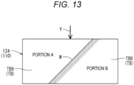
- Fig. 13 illustrates a joining line W of a tailored blank material TB in a vertical wall portion 124 of a center pillar outer member 110 of the related art and a pressing direction Y As illustrated in Fig. 13 , in the case of the related art, the pressing direction Y is different from the direction of the joining line W of the tailored blank material TB.
- the thickness of the steel plate in the A portion TB9 having a high material strength is difficult to change in the pressing direction Y during press molding, and the thickness of the steel plate in the B portion TB8 having a low material strength tends to change in the pressing direction Y during press molding.
- the one with a higher material strength does not move and the one with a lower material strength moves, the one with the lower material strength is pulled in the pressing direction Y, and a crack may occur at the joining line W between the A portion TB9 and the B portion TB8.
- a vehicle center pillar member formed to have a hat-shaped cross-section by press-molding a tailored blank material formed by joining a plurality of members in a longitudinal direction along at least one joining line, the vehicle center pillar member including a top plate portion and vertical wall portions on both sides of the top plate portion, in which the at least one joining line of the tailored blank material in the vertical wall portions is in the same direction as a pressing direction during press molding.
- the at least one joining line is bent in such a shape that members on both sides forming the tailored blank material are fitted together in a concave-convex manner in the top plate portion.
- the at least one joining line extends linearly from joining lines formed on the vertical wall portions on the both sides to the top plate portion and is connected to form one corner in the top plate portion.
- the at least one joining line extends linearly from the vertical wall portions on the both sides to the top plate portion, and is connected via an arc-shaped portion in the top plate portion.
- the at least one joining line extends linearly from the vertical wall portions on the both sides to the top plate portion, and is connected via another linear portion in the top plate portion, to form two corners at both ends of the linear portion.
- a lower door hinge mounting portion, a joining portion to a side sill of a vehicle body, and a widened region between the lower door hinge mounting portion and the joining portion are included, and one of the at least one joining line is located in the widened region.
- the vehicle center pillar member is molded by forming the tailored blank material so that the at least one joining line in the vertical wall portion is in the same direction as the pressing direction, and by pressing the tailored blank material in the pressing direction.
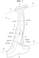
- Fig. 1 illustrates a perspective view of a center pillar provided on a side of a vehicle body of a passenger car as one embodiment.
- the center pillar is normally configured as a closed cross-section structural member from an outer member and an inner member, but Fig. 1 illustrates only a center pillar outer member 10.
- the center pillar outer member 10 is arranged in such a manner that its longitudinal direction is a height direction of a vehicle (an up and down direction as viewed in Fig. 1 ), and includes mounting portions 12 and 14 at upper and lower ends and a middle beam portion 16.
- the mounting portion 12 at the upper end is joined to a roof 18 and the mounting portion 14 at the lower end is joined to a side sill 20.
- the mounting portions 12 and 14 at the upper and lower ends are formed in T-shapes in order to increase a joining area with the roof 18 and the side sill 20, and are formed into a complicated shape by drawing or the like.
- the middle beam portion 16 has a relatively simple shape.
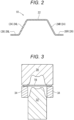
- Fig. 2 schematically illustrates a basic shape of a cross-section of the center pillar outer member 10 taken along a line II-II in Fig. 1 .
- the center pillar outer member 10 is formed to have a hat-shaped cross-section.
- the hat-shaped cross-section is generally formed by a central top plate portion 22, vertical wall portions 24 located on both sides of the top plate portion 22, and flange portions 26 located on both sides of the vertical wall portions 24.
- the vertical wall portions 24 include a vertical wall portion 24L on a vehicle front side (left side as viewed in Fig.
- ridge lines 27 are formed at boundaries between the top plate portion 22 and the vertical wall portions 24, and a width between ridge lines 27L and 27R on the left and right varies in the longitudinal direction. For example, a width of the beam portion 16 widens from top to bottom.
- the top plate portion 22 in the middle beam portion 16 is, at two upper and lower positions, provided with door hinge mounting portions 28U and 28D for mounting hinges (not illustrated) of a rear door provided on the rear side (right side as viewed in Fig. 2 ) of the center pillar outer member 10.
- the center pillar outer member 10 illustrated in Fig. 1 is formed by press molding from a tailored blank material TB formed by joining a plurality of members in the longitudinal direction, but in Fig. 1 , a joining line forming the tailored blank material TB is omitted.
- Figs. 3 to 5 illustrate a press molding process of the center pillar outer member 10.
- Fig. 3 illustrates a point in time when an upper blade 30 descending from a top dead center and a blank holder 34 come into contact with the tailored blank material TB.
- Fig. 4 illustrates a state in the middle of molding.
- Fig. 5 illustrates a state after molding (of a bottom dead center).
- the press molding process performs drawing, and the movable upper blade 30 is moved toward a lower punch 32 to draw the tailored blank material TB, to mold the center pillar outer member 10 having the hat-shaped cross-section illustrated in Fig. 1 .
- a direction in which the movable upper blade 30 is moved is a pressing direction during press molding.
- a state before molding (of the top dead center) illustrated in Fig. 3 is a state before molding in which the tailored blank material TB is sandwiched between the upper blade 30 and the blank holder 34 and set above the punch 32. Note that the upper blade 30 and the blank holder 34 move downward integrally from this state.
- the state in the middle of molding illustrated in Fig. 4 illustrates the state in the middle of molding in which the upper blade 30 is moved downward from the state in Fig. 3 , and an upper surface of the punch 32 pushes up a central portion of the tailored blank material TB for draw forming. Note that a position of the tailored blank material TB indicated by a broken line in Fig. 4 indicates a position of the tailored blank material TB before molding as illustrated in Fig. 3 .
- the state after molding (of the bottom dead center) illustrated in Fig 5 illustrates a state in which molding of the center pillar outer member 10 having the hat-shaped cross-section is completed with the upper blade 30 moved to the bottom dead center of the press molding.
- the position of the tailored blank material TB indicated by the broken lines in Fig. 5 indicates the position of the tailored blank material TB before molding as illustrated in Fig. 3 , as in the case of Fig. 4 .
- the upper blade 30 in the press molding of the present embodiment may be called an upper die, and similarly, the punch 32 and the blank holder 34 may be called a lower die.
- Fig. 6 illustrates a side view as seen from a lateral direction of the vehicle
- Fig. 7 illustrates a view as seen from an arrow VII in Fig. 6
- solid lines indicate the center pillar outer member 10 after press molding
- two-dot chain lines indicate a state of the tailored blank material TB before press molding. Therefore, the state of the tailored blank material TB indicated by the two-dot chain lines becomes the center pillar outer member 10 indicated by the solid lines by press molding.
- the tailored blank material TB is formed in an elongated shape by joining three plate members in the longitudinal direction.
- These three plate members include an upper member TB1, a central member TB2 and a lower member TB3, the upper member TB1 and the central member TB2 are integrally joined at a first joining line 36, and the central member TB2 and the lower member TB3 are integrally joined at a second joining line 38.
- This integral joining is usually performed by welding (tailored welded blank).
- the upper member TB1 is a portion corresponding to the mounting portion 12 at the upper end described above, and the lower member TB3 a portion corresponding to the mounting portion 14 at the lower end.
- the central member TB2 is a stronger member than the upper member TB1 and the lower member TB3.
- the first joining line 36 is formed between the mounting portion 12 at the upper end and the beam portion 16
- the second joining line 38 is formed between the beam portion 16 and the mounting portion 14 at the lower end.
- the second joining line 38 is formed between the door hinge mounting portion 28D for mounting a lower hinge of the rear door and a joining portion to the side sill 20 (see Fig. 1 ).
- combinations of tailored blank materials TB to be joined include, for example: a combination of members having the same strength, one having a thick plate thickness and the other having a thin plate thickness; a combination of members having the same plate thickness but different strengths; and a combination of members having different thicknesses and strengths.
- the material is generally a combination of steel plates, but there is also a combination of steel and a different material such as aluminum.
- the shapes of the joining lines 36 and 38 of the tailored blank material TB are formed such that portions L1, L2, R1, and R2 passing through the vertical wall portions 24L and 24R after molding are in the same direction as the pressing direction Y during molding as illustrated in Fig. 7 .
- a portion of the first joining line 36 formed on the vertical wall portion 24L on the vehicle front side (left side as viewed in Fig. 6 ) is denoted by a reference numeral L1
- a portion formed on the vertical wall portion 24R on the vehicle rear side (right side) is denoted by a reference numeral R1.
- a portion of the second joining line 38 formed on the vertical wall portion 24L on the vehicle front side left side as viewed in Fig.
- a portion formed on the vertical wall portion 24R on the vehicle rear side (right side) is denoted by a reference numeral R2.
- the right side portion R2 of the second joining line 38 which should not be visible from a viewing direction in Fig. 7 (the arrow VII in Fig. 6 ), is also indicated by a solid line.
- the pressing direction is indicated by an arrow Y Therefore, the pressing direction Y and the portions L1 and L2 formed on the left vertical wall portion 24L described above of the joining lines 36 and 38 are in the same direction.
- the pressing direction Y and the portions R1 and R2 of the joining lines 36 and 38 formed on the right vertical wall portion 24R described above are also in the same direction.
- the pressing direction Y is set in consideration of springback of the center pillar outer member 10 after press molding.
- the pressing direction Y is set so that an amount of springback between an upper portion (the L1 side) and a lower portion (the L2 side) of the center pillar outer member 10 is within a range of 5% to 10% in the pressing direction Y depending on a tensile strength of the steel plate.
- the reason why the portions L1 and L2 formed on the left vertical wall portion 24L and the portions R1 and R2 formed on the right vertical wall portion 24R of the joining lines 36 and 38 are set in the same direction as the pressing direction Y is that in the press molding process described above, it is taken into consideration that a pressing load of the drawing acts on the vertical wall portions 24L and 24R in particular.
- press molding after the tailored blank material TB is set as illustrated in Fig. 3 , the drawing is performed as illustrated in Figs. 4 and 5 to form the center pillar outer member 10 indicated by the solid lines. Then, during the drawing, the directions of the portions L1, L2, R1, and R2 formed on the vertical wall portions 24L and 24R of the joining lines 36 and 38 are the same as the pressing direction Y as illustrated in Fig. 7 .
- the joining lines 36 and 38 are joining lines for joining a plurality of plate members TB1, TB2, and TB3 constituting the tailored blank material TB, and the second joining line 38 of them is a line for joining the beam portion 16 and the mounting portion 14 at the lower end.
- the second joining line 38 is formed in a widened region between the door hinge mounting portion 28D for mounting the lower hinge of the rear door and the joining portion to the side sill 20 (see Fig. 1 ) of the vehicle body.
- the second joining line 38 is formed by extending the portions L2 and R2 formed on the vertical wall portions 24L and 24R on both sides of the center pillar outer member 10 to the top plate portion 22 and connecting them to each other at the top plate portion 22.
- a lower edge of the beam portion 16 is convex, and an upper edge of the mounting portion 14 at the lower end is concave, so that they are joined in a concave-convex fitting 52 in the longitudinal direction.
- the second joining line 38 in the configuration of the tailored blank material TB, can be extended straight directly from the portions L2 and R2 formed on the vertical wall portions 24L and 24R to the top plate portion 22 and be connected to an arc 40 at the top plate portion 22.
- a form of the concave-convex fitting 52 of the second joining line 38 is the arc 40 in this manner, it is possible to avoid stress concentration on the second joining line 38 of the top plate portion 22 during press molding of the center pillar outer member 10 or when the vehicle is subjected to a side impact.
- the second joining line 38 has extension portions 50 and 51 linearly extending from the portions L2 and R2 formed on the vertical wall portions 24L and 24R to the top plate portion 22, where the extension portions 50 and 51 can be connected to each other via another linear portion 42.
- corners 44 and 46 are formed at intersections (both ends of the linear portion 42) between the linear portion 42 and the extension portions 50 and 51 described above.
- the yield can be improved.
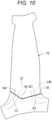
- the second joining line 38 can be extended straight directly from the portions L2 and R2 formed on the vertical wall portions 24L and 24R to the top plate portion 22 and formed with a corner 48 at one point.
- the second joining line 38 drawn by the two-dot chain lines in Fig. 6 is a virtual representation of the second joining line 38 of the tailored blank material TB in Fig. 10 .
- the second joining line 38 has such a simple shape, it is easy to form the second joining line 38.
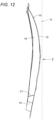
- Figs. 11 and 12 illustrate a center pillar outer member 110 of the related art.
- Fig. 11 corresponds to Fig. 6 of the embodiment described above
- Fig. 12 corresponds to Fig. 7 .
- a general joining line 138 of the related art is formed linearly in the configuration of the tailored blank material TB. Therefore, during press molding, as illustrated in Fig. 12 , directions of portions L3 and R3 located on the vertical wall portions 24L and 24R of the joining line 138 are different from that of the pressing direction Y during molding.
- the portions L1, L2, R1, and R2 formed on the vertical wall portions 24L and 24R of the joining lines 36 and 38 are formed to be in the same direction as the pressing direction Y during molding. This can avoid or reduce occurrence of a crack in the first joining line 36 and the second joining line 38.
- the lower portion of the center pillar outer member 10 where the second joining line 38 is formed is the widened region between the door hinge mounting portion 28D for mounting the lower hinge of the rear door and the joining portion to the side sill 20 of the vehicle body.
- the form of the joining line in the top plate portion 22 is not limited to the forms illustrated in Figs. 8 to 10 , and may be another form.
- center pillar outer member described above can also be applied to a center pillar inner member.
- At least one joining line of the tailored blank material in the vertical wall portions is in the same direction as the pressing direction during press molding.
- the at least one joining line is bent in such a shape that members on both sides forming the tailored blank material are fitted together in a concave-convex manner in the top plate portion.
- combination in the width direction is performed with high accuracy.
- the at least one joining line extends linearly from joining lines formed on the vertical wall portions on the both sides to the top plate portion and connected to form one corner in the top plate portion. According to this configuration, since the joining line has a simple form, it is easy to form the joining line.
- the at least one joining line extends linearly from the vertical wall portions on the both sides to the top plate portion, and is connected via an arc-shaped portion in the top plate portion. According to this configuration, it is possible to avoid stress concentration during press molding of the center pillar member or when the vehicle is subjected to a side impact (at the time of side impact).
- the at least one joining line extends linearly from the vertical wall portions on the both sides to the top plate portion, and is connected via another linear portion in the top plate portion, to form two corners at both ends of the linear portion. According to this configuration, it is possible to reduce the length in the longitudinal direction of one member of the tailored blank material to be combined to form the center pillar member compared to a configuration of being connected at the one corner or the arc-shaped portion described above. Thus, the yield can be improved.
- the center pillar member has a lower door hinge mounting portion, the joining portion to the side sill of the vehicle body, and the widened region between the lower door hinge mounting portion and the joining portion, and one of the at least one joining line is located in the widened region of the center pillar member. Since the joining line formed on the vertical wall portion of the widened region is particularly susceptible to cracking during press molding, an effect of restraining the cracking is significant.
Landscapes
- Engineering & Computer Science (AREA)
- Mechanical Engineering (AREA)
- Chemical & Material Sciences (AREA)
- Combustion & Propulsion (AREA)
- Transportation (AREA)
- Body Structure For Vehicles (AREA)
- Shaping Metal By Deep-Drawing, Or The Like (AREA)
Abstract
Description
- Embodiments disclosed in this application relate to a vehicle center pillar member and a method for manufacturing the same. In particular, the embodiments relate to a technique of forming a vehicle center pillar member having a hat-shaped cross-section by press molding using a tailored blank material.
- A vehicle such as an automobile is provided with a center pillar (commonly known as a B pillar) as a structural member on a side of a vehicle body. The center pillar is disposed on the side of the vehicle body with its longitudinal direction being a vehicle height direction. Normally, the center pillar includes an outer member and an inner member, and the outer member has a hat-shaped cross-section perpendicular to the longitudinal direction. The hat-shaped cross-section has a central top plate portion and vertical wall portions on both sides of the central top plate portion. The vertical wall portion is a member provided in the width direction of the vehicle. A boundary between the top plate portion and the vertical wall portion is bent to form a ridge line in the longitudinal direction. The distance between the two ridge lines formed on the both sides, that is, the width of the top plate portion normally varies in the longitudinal direction. The width usually widens from top to bottom.
- The vehicle center pillar member is usually made of steel plate and formed by pressing. Then, in order to reduce the weight of the center pillar member, by using a tailored blank material formed by joining a plurality of steel plate members, a plate thickness of the steel plate is increased only in a portion where strength is required, or a steel plate with high tensile strength is used (see
JP-A-2018-122733 - By the way, since the tailored blank material is formed by joining a plurality of members by welding or the like, a joining line is formed between adjacent members to be joined. When the center pillar member having the hat-shaped cross-section is press-molded using the tailored blank material, the vertical wall portion is also processed by being applied with a pressing load. Conventionally, a relative arrangement of a pressing direction and a direction of the joining line of the tailored blank material is not considered at all, and the directions do not match in reality.
-
Fig. 13 illustrates a joining line W of a tailored blank material TB in avertical wall portion 124 of a center pillarouter member 110 of the related art and a pressing direction Y As illustrated inFig. 13 , in the case of the related art, the pressing direction Y is different from the direction of the joining line W of the tailored blank material TB. - Since the steel plate members on both sides of the joining line W of the tailored blank material TB have different tensile strengths and plate thicknesses, when the pressing direction Y and a forming direction of the joining line W are different as illustrated in
Fig. 13 , there is a possibility that a crack occurs along the joining line W during press molding due to a difference in strength between the both sides of the joining line W. InFig. 13 , when a material strength of an A portion TB9 is high and a material strength of a B portion TB8 is low in the tailored blank material TB, an area where a crack may occur due to the difference in strength is indicated by hatched lines. - Specifically, the thickness of the steel plate in the A portion TB9 having a high material strength is difficult to change in the pressing direction Y during press molding, and the thickness of the steel plate in the B portion TB8 having a low material strength tends to change in the pressing direction Y during press molding. When there is a difference in material strength between the A portion TB9 and the B portion TB8 at the joining line W in this way, since the one with a higher material strength does not move and the one with a lower material strength moves, the one with the lower material strength is pulled in the pressing direction Y, and a crack may occur at the joining line W between the A portion TB9 and the B portion TB8.
- Therefore, it is desired to avoid or restrain the crack from occurring from the joining line of the vertical wall portion when press-molding the center pillar member having the hat-shaped cross-section using the tailored blank material.
- According to one embodiment, a vehicle center pillar member formed to have a hat-shaped cross-section by press-molding a tailored blank material formed by joining a plurality of members in a longitudinal direction along at least one joining line, the vehicle center pillar member including a top plate portion and vertical wall portions on both sides of the top plate portion, in which the at least one joining line of the tailored blank material in the vertical wall portions is in the same direction as a pressing direction during press molding.
- According to the embodiment, in a configuration of the tailored blank material, the at least one joining line is bent in such a shape that members on both sides forming the tailored blank material are fitted together in a concave-convex manner in the top plate portion.
- According to the embodiment, in the configuration of the tailored blank material, the at least one joining line extends linearly from joining lines formed on the vertical wall portions on the both sides to the top plate portion and is connected to form one corner in the top plate portion.
- According to the embodiment, in the configuration of the tailored blank material, the at least one joining line extends linearly from the vertical wall portions on the both sides to the top plate portion, and is connected via an arc-shaped portion in the top plate portion.
- According to the embodiment, in the configuration of the tailored blank material, the at least one joining line extends linearly from the vertical wall portions on the both sides to the top plate portion, and is connected via another linear portion in the top plate portion, to form two corners at both ends of the linear portion.
- According to the embodiment, a lower door hinge mounting portion, a joining portion to a side sill of a vehicle body, and a widened region between the lower door hinge mounting portion and the joining portion are included, and one of the at least one joining line is located in the widened region.
- According to another embodiment, in a method for manufacturing the aforementioned vehicle center pillar member, the vehicle center pillar member is molded by forming the tailored blank material so that the at least one joining line in the vertical wall portion is in the same direction as the pressing direction, and by pressing the tailored blank material in the pressing direction.
-
-
Fig. 1 is a perspective view illustrating an external configuration of a center pillar outer member as one embodiment; -
Fig. 2 is a cross-sectional view schematically illustrating a basic configuration of a cross-section of the center pillar outer member taken along a line II-II inFig. 1 ; -
Fig. 3 is a view illustrating a point in time when an upper blade descending from a top dead center and a blank holder come into contact with a tailored blank material in a press molding process of the center pillar outer member; -
Fig. 4 is a view illustrating a state in the middle of molding in the press molding process of the center pillar outer member; -
Fig. 5 is a view illustrating a state after molding (of a bottom dead center) in the press molding process of the center pillar outer member; -
Fig. 6 is a side view of the center pillar outer member as seen from a side of a vehicle; -
Fig. 7 is a view of the center pillar outer member as seen from an arrow VII inFig. 6 ; -
Fig. 8 is a view illustrating a second joining line formed in the tailored blank material as one embodiment; -
Fig. 9 is a view illustrating the second joining line as another embodiment; -
Fig. 10 is a view illustrating the second joining line as still another embodiment; -
Fig. 11 is a side view of a center pillar outer member of the related art as seen from the side of the vehicle and corresponding toFig. 6 ; -
Fig. 12 is a view of the center pillar outer member as seen from an arrow XII inFig. 11 ; and -
Fig. 13 is a view illustrating a joining line of the tailored blank material in a vertical wall portion of the related art and a pressing direction during molding. - Hereinafter, various embodiments will be described with reference to the drawings. Note that directions such as up and down, front and rear, left and right in the description using the drawings indicate directions in the drawings. However, directions indicated individually are according to the individual indication. In addition, when there are corresponding component parts on the left and right, and referring to the left and right parts individually, L is added to the left part and R is added to the right part at an end of reference numerals indicating the parts.
-
Fig. 1 illustrates a perspective view of a center pillar provided on a side of a vehicle body of a passenger car as one embodiment. Specifically, the center pillar is normally configured as a closed cross-section structural member from an outer member and an inner member, butFig. 1 illustrates only a center pillarouter member 10. The center pillarouter member 10 is arranged in such a manner that its longitudinal direction is a height direction of a vehicle (an up and down direction as viewed inFig. 1 ), and includes mountingportions middle beam portion 16. Themounting portion 12 at the upper end is joined to aroof 18 and themounting portion 14 at the lower end is joined to aside sill 20. Note that in general, themounting portions roof 18 and theside sill 20, and are formed into a complicated shape by drawing or the like. Themiddle beam portion 16 has a relatively simple shape. -
Fig. 2 schematically illustrates a basic shape of a cross-section of the center pillarouter member 10 taken along a line II-II inFig. 1 . The center pillarouter member 10 is formed to have a hat-shaped cross-section. The hat-shaped cross-section is generally formed by a centraltop plate portion 22,vertical wall portions 24 located on both sides of thetop plate portion 22, andflange portions 26 located on both sides of thevertical wall portions 24. Note that thevertical wall portions 24 include avertical wall portion 24L on a vehicle front side (left side as viewed inFig. 2 ) and avertical wall portion 24R on a vehicle rear side (right side), and theflange portions 26 also include aflange portion 26L on the left side and aflange portion 26R on the right side. As illustrated inFig. 1 ,ridge lines 27 are formed at boundaries between thetop plate portion 22 and thevertical wall portions 24, and a width betweenridge lines beam portion 16 widens from top to bottom. - As illustrated in
Fig. 1 , thetop plate portion 22 in themiddle beam portion 16 is, at two upper and lower positions, provided with doorhinge mounting portions Fig. 2 ) of the center pillarouter member 10. Note that the center pillarouter member 10 illustrated inFig. 1 is formed by press molding from a tailored blank material TB formed by joining a plurality of members in the longitudinal direction, but inFig. 1 , a joining line forming the tailored blank material TB is omitted. -
Figs. 3 to 5 illustrate a press molding process of the center pillarouter member 10.Fig. 3 illustrates a point in time when anupper blade 30 descending from a top dead center and ablank holder 34 come into contact with the tailored blank material TB.Fig. 4 illustrates a state in the middle of molding.Fig. 5 illustrates a state after molding (of a bottom dead center). Specifically, the press molding process performs drawing, and the movableupper blade 30 is moved toward alower punch 32 to draw the tailored blank material TB, to mold the center pillarouter member 10 having the hat-shaped cross-section illustrated inFig. 1 . Note that a direction in which the movableupper blade 30 is moved is a pressing direction during press molding. - A state before molding (of the top dead center) illustrated in
Fig. 3 is a state before molding in which the tailored blank material TB is sandwiched between theupper blade 30 and theblank holder 34 and set above thepunch 32. Note that theupper blade 30 and theblank holder 34 move downward integrally from this state. - The state in the middle of molding illustrated in
Fig. 4 illustrates the state in the middle of molding in which theupper blade 30 is moved downward from the state inFig. 3 , and an upper surface of thepunch 32 pushes up a central portion of the tailored blank material TB for draw forming. Note that a position of the tailored blank material TB indicated by a broken line inFig. 4 indicates a position of the tailored blank material TB before molding as illustrated inFig. 3 . - The state after molding (of the bottom dead center) illustrated in
Fig 5 illustrates a state in which molding of the center pillarouter member 10 having the hat-shaped cross-section is completed with theupper blade 30 moved to the bottom dead center of the press molding. Note that the position of the tailored blank material TB indicated by the broken lines inFig. 5 indicates the position of the tailored blank material TB before molding as illustrated inFig. 3 , as in the case ofFig. 4 . Note that theupper blade 30 in the press molding of the present embodiment may be called an upper die, and similarly, thepunch 32 and theblank holder 34 may be called a lower die. - Next, a detailed configuration of the center pillar
outer member 10 will be described with reference toFigs. 6 and7 .Fig. 6 illustrates a side view as seen from a lateral direction of the vehicle, andFig. 7 illustrates a view as seen from an arrow VII inFig. 6 . Note that inFigs. 6 and7 , solid lines indicate the center pillarouter member 10 after press molding, and two-dot chain lines indicate a state of the tailored blank material TB before press molding. Therefore, the state of the tailored blank material TB indicated by the two-dot chain lines becomes the center pillarouter member 10 indicated by the solid lines by press molding. - As indicated by the two-dot chain lines in
Fig. 6 , the tailored blank material TB is formed in an elongated shape by joining three plate members in the longitudinal direction. These three plate members include an upper member TB1, a central member TB2 and a lower member TB3, the upper member TB1 and the central member TB2 are integrally joined at a first joiningline 36, and the central member TB2 and the lower member TB3 are integrally joined at a second joiningline 38. This integral joining is usually performed by welding (tailored welded blank). Note that the upper member TB1 is a portion corresponding to the mountingportion 12 at the upper end described above, and the lower member TB3 a portion corresponding to the mountingportion 14 at the lower end. Generally, the central member TB2 is a stronger member than the upper member TB1 and the lower member TB3. - In the present embodiment, the first joining
line 36 is formed between the mountingportion 12 at the upper end and thebeam portion 16, and the second joiningline 38 is formed between thebeam portion 16 and the mountingportion 14 at the lower end. Specifically, the second joiningline 38 is formed between the doorhinge mounting portion 28D for mounting a lower hinge of the rear door and a joining portion to the side sill 20 (seeFig. 1 ). Note that combinations of tailored blank materials TB to be joined include, for example: a combination of members having the same strength, one having a thick plate thickness and the other having a thin plate thickness; a combination of members having the same plate thickness but different strengths; and a combination of members having different thicknesses and strengths. The material is generally a combination of steel plates, but there is also a combination of steel and a different material such as aluminum. - The shapes of the joining
lines vertical wall portions Fig. 7 . InFig. 7 , a portion of the first joiningline 36 formed on thevertical wall portion 24L on the vehicle front side (left side as viewed inFig. 6 ) is denoted by a reference numeral L1, and a portion formed on thevertical wall portion 24R on the vehicle rear side (right side) is denoted by a reference numeral R1. Similarly, a portion of the second joiningline 38 formed on thevertical wall portion 24L on the vehicle front side (left side as viewed inFig. 6 ) is denoted by a reference numeral L2, and a portion formed on thevertical wall portion 24R on the vehicle rear side (right side) is denoted by a reference numeral R2. Note that inFig. 7 , for convenience of understanding, the right side portion R2 of the second joiningline 38, which should not be visible from a viewing direction inFig. 7 (the arrow VII inFig. 6 ), is also indicated by a solid line. Further, inFig. 7 , the pressing direction is indicated by an arrow Y Therefore, the pressing direction Y and the portions L1 and L2 formed on the leftvertical wall portion 24L described above of the joininglines lines vertical wall portion 24R described above are also in the same direction. - As one embodiment, the pressing direction Y is set in consideration of springback of the center pillar
outer member 10 after press molding. For example, the pressing direction Y is set so that an amount of springback between an upper portion (the L1 side) and a lower portion (the L2 side) of the center pillarouter member 10 is within a range of 5% to 10% in the pressing direction Y depending on a tensile strength of the steel plate. - The reason why the portions L1 and L2 formed on the left
vertical wall portion 24L and the portions R1 and R2 formed on the rightvertical wall portion 24R of the joininglines vertical wall portions Fig. 3 , the drawing is performed as illustrated inFigs. 4 and 5 to form the center pillarouter member 10 indicated by the solid lines. Then, during the drawing, the directions of the portions L1, L2, R1, and R2 formed on thevertical wall portions lines Fig. 7 . - Next, the position and shape of the second joining
line 38 set at the lower portion of the tailored blank material TB forming the center pillarouter member 10 in the above embodiment will be described. As illustrated inFig. 6 , the joininglines line 38 of them is a line for joining thebeam portion 16 and the mountingportion 14 at the lower end. The second joiningline 38 is formed in a widened region between the doorhinge mounting portion 28D for mounting the lower hinge of the rear door and the joining portion to the side sill 20 (seeFig. 1 ) of the vehicle body. - In the configuration of the tailored blank material TB, the second joining
line 38 is formed by extending the portions L2 and R2 formed on thevertical wall portions outer member 10 to thetop plate portion 22 and connecting them to each other at thetop plate portion 22. In thetop plate portion 22, a lower edge of thebeam portion 16 is convex, and an upper edge of the mountingportion 14 at the lower end is concave, so that they are joined in a concave-convex fitting 52 in the longitudinal direction. - As illustrated in
Fig. 8 , as one embodiment, in the configuration of the tailored blank material TB, the second joiningline 38 can be extended straight directly from the portions L2 and R2 formed on thevertical wall portions top plate portion 22 and be connected to anarc 40 at thetop plate portion 22. When a form of the concave-convex fitting 52 of the second joiningline 38 is thearc 40 in this manner, it is possible to avoid stress concentration on the second joiningline 38 of thetop plate portion 22 during press molding of the center pillarouter member 10 or when the vehicle is subjected to a side impact. - As illustrated in
Fig. 9 , as another embodiment, in the configuration of the tailored blank material TB, the second joiningline 38 hasextension portions vertical wall portions top plate portion 22, where theextension portions linear portion 42. Thus,corners linear portion 42 and theextension portions outer member 10 compared to the cases of the above-described embodiment 1 and a below-described embodiment 3. Thus, the yield can be improved. - As illustrated in
Fig. 10 , as still another embodiment, in the configuration of the tailored blank material TB, the second joiningline 38 can be extended straight directly from the portions L2 and R2 formed on thevertical wall portions top plate portion 22 and formed with acorner 48 at one point. Note that the second joiningline 38 drawn by the two-dot chain lines inFig. 6 is a virtual representation of the second joiningline 38 of the tailored blank material TB inFig. 10 . When the second joiningline 38 has such a simple shape, it is easy to form the second joiningline 38. -
Figs. 11 and12 illustrate a center pillarouter member 110 of the related art.Fig. 11 corresponds toFig. 6 of the embodiment described above, andFig. 12 corresponds toFig. 7 . As can be seen fromFig. 11 , a general joiningline 138 of the related art is formed linearly in the configuration of the tailored blank material TB. Therefore, during press molding, as illustrated inFig. 12 , directions of portions L3 and R3 located on thevertical wall portions line 138 are different from that of the pressing direction Y during molding. When the portions L3 and R3 located on thevertical wall portions line 138 are in directions different from the pressing direction Y, as described at the beginning of this specification, there is a possibility that a crack occurs along the joiningline 138 due to a difference in strength between both sides of the portions L3 and R3. - In contrast, according to the embodiments described above, as illustrated in
Fig. 7 , the portions L1, L2, R1, and R2 formed on thevertical wall portions lines line 36 and the second joiningline 38. - In particular, in the above embodiments, the lower portion of the center pillar
outer member 10 where the second joiningline 38 is formed is the widened region between the doorhinge mounting portion 28D for mounting the lower hinge of the rear door and the joining portion to theside sill 20 of the vehicle body. When the joining line is formed in such a region, since a crack is likely to occur along the joining line, an effect of aligning the direction of the joining line with the pressing direction is significant. - In the above embodiments, there are three members constituting the tailored blank material TB, and there are two joining lines between them, but the present invention is not limited to this.
- Further, the form of the joining line in the
top plate portion 22 is not limited to the forms illustrated inFigs. 8 to 10 , and may be another form. - Further, as another embodiment, features of the center pillar outer member described above can also be applied to a center pillar inner member.
- Finally, advantages of the above embodiments will be added.
- In the above embodiments, at least one joining line of the tailored blank material in the vertical wall portions is in the same direction as the pressing direction during press molding. Thus, even if there is a difference in strength between adjacent portions of the tailored blank material, a tensile stress generated at the joining line during press molding is small, so that occurrence of a crack from the joining line of the vertical wall portion of the center pillar member can be avoided or reduced.
- In some embodiments, in the configuration of the tailored blank material, the at least one joining line is bent in such a shape that members on both sides forming the tailored blank material are fitted together in a concave-convex manner in the top plate portion. Thus, combination in the width direction is performed with high accuracy.
- In some embodiments, in the configuration of the tailored blank material, the at least one joining line extends linearly from joining lines formed on the vertical wall portions on the both sides to the top plate portion and connected to form one corner in the top plate portion. According to this configuration, since the joining line has a simple form, it is easy to form the joining line.
- In some embodiments, in the configuration of the tailored blank material, the at least one joining line extends linearly from the vertical wall portions on the both sides to the top plate portion, and is connected via an arc-shaped portion in the top plate portion. According to this configuration, it is possible to avoid stress concentration during press molding of the center pillar member or when the vehicle is subjected to a side impact (at the time of side impact).
- In some embodiments, in the configuration of the tailored blank material, the at least one joining line extends linearly from the vertical wall portions on the both sides to the top plate portion, and is connected via another linear portion in the top plate portion, to form two corners at both ends of the linear portion. According to this configuration, it is possible to reduce the length in the longitudinal direction of one member of the tailored blank material to be combined to form the center pillar member compared to a configuration of being connected at the one corner or the arc-shaped portion described above. Thus, the yield can be improved.
- In some embodiments, the center pillar member has a lower door hinge mounting portion, the joining portion to the side sill of the vehicle body, and the widened region between the lower door hinge mounting portion and the joining portion, and one of the at least one joining line is located in the widened region of the center pillar member. Since the joining line formed on the vertical wall portion of the widened region is particularly susceptible to cracking during press molding, an effect of restraining the cracking is significant.
- Although specific embodiments have been described above, the present technique is not limited to those embodiments, and various modifications, substitutions, and improvements can be made by those skilled in the art.
Claims (7)
- A vehicle center pillar member formed to have a hat-shaped cross-section by press-molding a tailored blank material formed by joining a plurality of members in a longitudinal direction along at least one joining line,the vehicle center pillar member comprising a top plate portion and vertical wall portions on both sides of the top plate portion, whereinthe at least one joining line of the tailored blank material in the vertical wall portions is in the same direction as a pressing direction during press molding.
- The vehicle center pillar member according to claim 1, wherein in a configuration of the tailored blank material, the at least one joining line is bent in such a shape that members on both sides forming the tailored blank material are fitted together in a concave-convex manner in the top plate portion.
- The vehicle center pillar member according to claim 2, wherein in the configuration of the tailored blank material, the at least one joining line extends linearly from joining lines formed on the vertical wall portions on the both sides to the top plate portion and is connected to form one corner in the top plate portion.
- The vehicle center pillar member according to claim 2, wherein in the configuration of the tailored blank material, the at least one joining line extends linearly from the vertical wall portions on the both sides to the top plate portion, and is connected via an arc-shaped portion in the top plate portion.
- The vehicle center pillar member according to claim 2, wherein in the configuration of the tailored blank material, the at least one joining line extends linearly from the vertical wall portions on the both sides to the top plate portion, and is connected via another linear portion in the top plate portion, to form two corners at both ends of the linear portion.
- The vehicle center pillar member according to any one of claims 1 to 5, comprising a lower door hinge mounting portion, a joining portion to a side sill of a vehicle body, and a widened region between the lower door hinge mounting portion and the joining portion, wherein
one of the at least one joining line is located in the widened region. - A method for manufacturing the vehicle center pillar member according to any one of claims 1 to 6, comprising molding the vehicle center pillar member by forming the tailored blank material so that the at least one joining line in the vertical wall portion is in the same direction as the pressing direction, and by pressing the tailored blank material in the pressing direction.
Applications Claiming Priority (2)
| Application Number | Priority Date | Filing Date | Title |
|---|---|---|---|
| JP2020217162A JP7346377B2 (en) | 2020-12-25 | 2020-12-25 | Center pillar components for vehicles and their manufacturing method |
| PCT/JP2021/047844 WO2022138810A1 (en) | 2020-12-25 | 2021-12-23 | Vehicle center pillar member and method for manufacturing same |
Publications (2)
| Publication Number | Publication Date |
|---|---|
| EP4268988A1 true EP4268988A1 (en) | 2023-11-01 |
| EP4268988A4 EP4268988A4 (en) | 2024-11-20 |
Family
ID=82158745
Family Applications (1)
| Application Number | Title | Priority Date | Filing Date |
|---|---|---|---|
| EP21910949.3A Pending EP4268988A4 (en) | 2020-12-25 | 2021-12-23 | Vehicle center pillar member and method for manufacturing same |
Country Status (5)
| Country | Link |
|---|---|
| US (1) | US12508644B2 (en) |
| EP (1) | EP4268988A4 (en) |
| JP (1) | JP7346377B2 (en) |
| CN (1) | CN116547087A (en) |
| WO (1) | WO2022138810A1 (en) |
Families Citing this family (1)
| Publication number | Priority date | Publication date | Assignee | Title |
|---|---|---|---|---|
| CN122029096A (en) * | 2023-10-18 | 2026-05-12 | 日本制铁株式会社 | Impact absorbing member and vehicle body |
Family Cites Families (10)
| Publication number | Priority date | Publication date | Assignee | Title |
|---|---|---|---|---|
| JP2703857B2 (en) * | 1993-01-22 | 1998-01-26 | 本田技研工業株式会社 | Collective blank members |
| JP3419362B2 (en) * | 1999-10-05 | 2003-06-23 | 日産自動車株式会社 | Body superstructure, method of assembling body superstructure |
| JP5416498B2 (en) * | 2009-07-23 | 2014-02-12 | 本田技研工業株式会社 | Method and apparatus for forming tailored blank plate |
| DE102010036450B9 (en) * | 2010-07-16 | 2020-09-03 | Thyssenkrupp Steel Europe Ag | B-pillar reinforcement of a motor vehicle |
| JP2012148332A (en) * | 2011-01-21 | 2012-08-09 | Unipres Corp | Method of manufacturing tailored blank material |
| DE102011078032A1 (en) * | 2011-06-24 | 2012-12-27 | Aleris Aluminum Koblenz Gmbh | Vehicle component and method for its production |
| JP6049146B2 (en) | 2014-09-24 | 2016-12-21 | 富士重工業株式会社 | Body frame structure |
| JP6679510B2 (en) | 2017-02-01 | 2020-04-15 | 豊田鉄工株式会社 | Pillar components for vehicles |
| JP6704870B2 (en) * | 2017-03-14 | 2020-06-03 | 豊田鉄工株式会社 | Bumper reinforcement |
| JP2020203508A (en) | 2019-06-14 | 2020-12-24 | マツダ株式会社 | Vehicle body side part structure |
-
2020
- 2020-12-25 JP JP2020217162A patent/JP7346377B2/en active Active
-
2021
- 2021-12-23 CN CN202180080808.3A patent/CN116547087A/en active Pending
- 2021-12-23 US US18/258,291 patent/US12508644B2/en active Active
- 2021-12-23 WO PCT/JP2021/047844 patent/WO2022138810A1/en not_active Ceased
- 2021-12-23 EP EP21910949.3A patent/EP4268988A4/en active Pending
Also Published As
| Publication number | Publication date |
|---|---|
| US20240051012A1 (en) | 2024-02-15 |
| EP4268988A4 (en) | 2024-11-20 |
| CN116547087A (en) | 2023-08-04 |
| JP2022102435A (en) | 2022-07-07 |
| JP7346377B2 (en) | 2023-09-19 |
| WO2022138810A1 (en) | 2022-06-30 |
| US12508644B2 (en) | 2025-12-30 |
Similar Documents
| Publication | Publication Date | Title |
|---|---|---|
| CN105102309B (en) | Automobile body lateral-portion structure | |
| CN109969264B (en) | Method for manufacturing vehicle body member and vehicle body member | |
| CN112703130B (en) | Bumper beam with steel reinforcements | |
| EP2823928B1 (en) | Coupling structure | |
| EP3501684B1 (en) | Automobile-body press-formed component and manufacturing method therefor | |
| US11020785B2 (en) | Method and apparatus for manufacturing press component | |
| RU2654403C2 (en) | Stamping-formed product, automobile construction element, including the product, method of manufacturing and device for manufacturing of the stamping-formed product | |
| CN109774792B (en) | Vehicle frame structure | |
| CN112839748B (en) | Reinforcing member for structural member for vehicle | |
| CN107074292A (en) | Method for producing a three-dimensional vehicle door frame interior reinforcement element, method for producing a vehicle door frame, and method for producing a vehicle reinforcement structure | |
| WO2016171229A1 (en) | Method for producing press-molded product, press-molded product, and pressing device | |
| JP7163270B2 (en) | center pillar reinforcement | |
| EP1911619A2 (en) | Door panel structure and method of producing the same | |
| US12508644B2 (en) | Vehicle center pillar member and method for manufacturing same | |
| EP3611058B1 (en) | Structural member for automobiles | |
| JP7399905B2 (en) | Press molds and press molded products | |
| JP4932688B2 (en) | Roof reinforcement for automobile bodies | |
| JP4785493B2 (en) | Collision reinforcing material for vehicle and manufacturing method thereof | |
| EP3932750B1 (en) | Structural member for vehicle | |
| CN112437704B (en) | Reinforcement member for structural parts for vehicles and method of manufacturing the same | |
| KR101914846B1 (en) | Automobile skeleton component and front pillar lower provided with same | |
| CN115379982A (en) | Strength member for vehicle |
Legal Events
| Date | Code | Title | Description |
|---|---|---|---|
| STAA | Information on the status of an ep patent application or granted ep patent |
Free format text: STATUS: THE INTERNATIONAL PUBLICATION HAS BEEN MADE |
|
| PUAI | Public reference made under article 153(3) epc to a published international application that has entered the european phase |
Free format text: ORIGINAL CODE: 0009012 |
|
| STAA | Information on the status of an ep patent application or granted ep patent |
Free format text: STATUS: REQUEST FOR EXAMINATION WAS MADE |
|
| 17P | Request for examination filed |
Effective date: 20230705 |
|
| AK | Designated contracting states |
Kind code of ref document: A1 Designated state(s): AL AT BE BG CH CY CZ DE DK EE ES FI FR GB GR HR HU IE IS IT LI LT LU LV MC MK MT NL NO PL PT RO RS SE SI SK SM TR |
|
| DAV | Request for validation of the european patent (deleted) | ||
| DAX | Request for extension of the european patent (deleted) | ||
| REG | Reference to a national code |
Ref country code: DE Ref legal event code: R079 Free format text: PREVIOUS MAIN CLASS: B21D0022200000 Ipc: B62D0025040000 |
|
| A4 | Supplementary search report drawn up and despatched |
Effective date: 20241018 |
|
| RIC1 | Information provided on ipc code assigned before grant |
Ipc: B62D 25/04 20060101AFI20241014BHEP |