EP4268938A1 - Electroswing carbon dioxide recovery system - Google Patents
Electroswing carbon dioxide recovery system Download PDFInfo
- Publication number
- EP4268938A1 EP4268938A1 EP23167930.9A EP23167930A EP4268938A1 EP 4268938 A1 EP4268938 A1 EP 4268938A1 EP 23167930 A EP23167930 A EP 23167930A EP 4268938 A1 EP4268938 A1 EP 4268938A1
- Authority
- EP
- European Patent Office
- Prior art keywords
- carbon dioxide
- recovery
- adsorption
- amount
- mode
- Prior art date
- Legal status (The legal status is an assumption and is not a legal conclusion. Google has not performed a legal analysis and makes no representation as to the accuracy of the status listed.)
- Pending
Links
Images



Classifications
-
- B—PERFORMING OPERATIONS; TRANSPORTING
- B01—PHYSICAL OR CHEMICAL PROCESSES OR APPARATUS IN GENERAL
- B01D—SEPARATION
- B01D53/00—Separation of gases or vapours; Recovering vapours of volatile solvents from gases; Chemical or biological purification of waste gases, e.g. engine exhaust gases, smoke, fumes, flue gases, aerosols
- B01D53/32—Separation of gases or vapours; Recovering vapours of volatile solvents from gases; Chemical or biological purification of waste gases, e.g. engine exhaust gases, smoke, fumes, flue gases, aerosols by electrical effects other than those provided for in group B01D61/00
- B01D53/326—Separation of gases or vapours; Recovering vapours of volatile solvents from gases; Chemical or biological purification of waste gases, e.g. engine exhaust gases, smoke, fumes, flue gases, aerosols by electrical effects other than those provided for in group B01D61/00 in electrochemical cells
-
- B—PERFORMING OPERATIONS; TRANSPORTING
- B01—PHYSICAL OR CHEMICAL PROCESSES OR APPARATUS IN GENERAL
- B01D—SEPARATION
- B01D53/00—Separation of gases or vapours; Recovering vapours of volatile solvents from gases; Chemical or biological purification of waste gases, e.g. engine exhaust gases, smoke, fumes, flue gases, aerosols
- B01D53/32—Separation of gases or vapours; Recovering vapours of volatile solvents from gases; Chemical or biological purification of waste gases, e.g. engine exhaust gases, smoke, fumes, flue gases, aerosols by electrical effects other than those provided for in group B01D61/00
-
- B—PERFORMING OPERATIONS; TRANSPORTING
- B01—PHYSICAL OR CHEMICAL PROCESSES OR APPARATUS IN GENERAL
- B01D—SEPARATION
- B01D53/00—Separation of gases or vapours; Recovering vapours of volatile solvents from gases; Chemical or biological purification of waste gases, e.g. engine exhaust gases, smoke, fumes, flue gases, aerosols
- B01D53/02—Separation of gases or vapours; Recovering vapours of volatile solvents from gases; Chemical or biological purification of waste gases, e.g. engine exhaust gases, smoke, fumes, flue gases, aerosols by adsorption, e.g. preparative gas chromatography
- B01D53/04—Separation of gases or vapours; Recovering vapours of volatile solvents from gases; Chemical or biological purification of waste gases, e.g. engine exhaust gases, smoke, fumes, flue gases, aerosols by adsorption, e.g. preparative gas chromatography with stationary adsorbents
-
- B—PERFORMING OPERATIONS; TRANSPORTING
- B01—PHYSICAL OR CHEMICAL PROCESSES OR APPARATUS IN GENERAL
- B01D—SEPARATION
- B01D53/00—Separation of gases or vapours; Recovering vapours of volatile solvents from gases; Chemical or biological purification of waste gases, e.g. engine exhaust gases, smoke, fumes, flue gases, aerosols
- B01D53/14—Separation of gases or vapours; Recovering vapours of volatile solvents from gases; Chemical or biological purification of waste gases, e.g. engine exhaust gases, smoke, fumes, flue gases, aerosols by absorption
- B01D53/1425—Regeneration of liquid absorbents
-
- B—PERFORMING OPERATIONS; TRANSPORTING
- B01—PHYSICAL OR CHEMICAL PROCESSES OR APPARATUS IN GENERAL
- B01D—SEPARATION
- B01D53/00—Separation of gases or vapours; Recovering vapours of volatile solvents from gases; Chemical or biological purification of waste gases, e.g. engine exhaust gases, smoke, fumes, flue gases, aerosols
- B01D53/14—Separation of gases or vapours; Recovering vapours of volatile solvents from gases; Chemical or biological purification of waste gases, e.g. engine exhaust gases, smoke, fumes, flue gases, aerosols by absorption
- B01D53/1456—Removing acid components
- B01D53/1475—Removing carbon dioxide
-
- B—PERFORMING OPERATIONS; TRANSPORTING
- B01—PHYSICAL OR CHEMICAL PROCESSES OR APPARATUS IN GENERAL
- B01D—SEPARATION
- B01D53/00—Separation of gases or vapours; Recovering vapours of volatile solvents from gases; Chemical or biological purification of waste gases, e.g. engine exhaust gases, smoke, fumes, flue gases, aerosols
- B01D53/34—Chemical or biological purification of waste gases
- B01D53/346—Controlling the process
-
- B—PERFORMING OPERATIONS; TRANSPORTING
- B01—PHYSICAL OR CHEMICAL PROCESSES OR APPARATUS IN GENERAL
- B01D—SEPARATION
- B01D53/00—Separation of gases or vapours; Recovering vapours of volatile solvents from gases; Chemical or biological purification of waste gases, e.g. engine exhaust gases, smoke, fumes, flue gases, aerosols
- B01D53/34—Chemical or biological purification of waste gases
- B01D53/46—Removing components of defined structure
- B01D53/62—Carbon oxides
-
- B—PERFORMING OPERATIONS; TRANSPORTING
- B01—PHYSICAL OR CHEMICAL PROCESSES OR APPARATUS IN GENERAL
- B01D—SEPARATION
- B01D2256/00—Main component in the product gas stream after treatment
- B01D2256/22—Carbon dioxide
-
- B—PERFORMING OPERATIONS; TRANSPORTING
- B01—PHYSICAL OR CHEMICAL PROCESSES OR APPARATUS IN GENERAL
- B01D—SEPARATION
- B01D2257/00—Components to be removed
- B01D2257/50—Carbon oxides
- B01D2257/504—Carbon dioxide
-
- Y—GENERAL TAGGING OF NEW TECHNOLOGICAL DEVELOPMENTS; GENERAL TAGGING OF CROSS-SECTIONAL TECHNOLOGIES SPANNING OVER SEVERAL SECTIONS OF THE IPC; TECHNICAL SUBJECTS COVERED BY FORMER USPC CROSS-REFERENCE ART COLLECTIONS [XRACs] AND DIGESTS
- Y02—TECHNOLOGIES OR APPLICATIONS FOR MITIGATION OR ADAPTATION AGAINST CLIMATE CHANGE
- Y02C—CAPTURE, STORAGE, SEQUESTRATION OR DISPOSAL OF GREENHOUSE GASES [GHG]
- Y02C20/00—Capture or disposal of greenhouse gases
- Y02C20/40—Capture or disposal of greenhouse gases of CO2
-
- Y—GENERAL TAGGING OF NEW TECHNOLOGICAL DEVELOPMENTS; GENERAL TAGGING OF CROSS-SECTIONAL TECHNOLOGIES SPANNING OVER SEVERAL SECTIONS OF THE IPC; TECHNICAL SUBJECTS COVERED BY FORMER USPC CROSS-REFERENCE ART COLLECTIONS [XRACs] AND DIGESTS
- Y02—TECHNOLOGIES OR APPLICATIONS FOR MITIGATION OR ADAPTATION AGAINST CLIMATE CHANGE
- Y02P—CLIMATE CHANGE MITIGATION TECHNOLOGIES IN THE PRODUCTION OR PROCESSING OF GOODS
- Y02P20/00—Technologies relating to chemical industry
- Y02P20/151—Reduction of greenhouse gas [GHG] emissions, e.g. CO2
Definitions
- the present disclosure relates to a carbon dioxide recovery system that recovers carbon dioxide from a mixed gas containing carbon dioxide.
- Patent Literature 1 JP 2018-533470 A has proposed a gas separation system that separates carbon dioxide from a mixed gas containing carbon dioxide by an electrochemical reaction.
- the mixed gas containing carbon dioxide is introduced into a housing in which an electrochemical cell is disposed.
- an electroactive material provided on the negative electrode is reduced. Therefore, the electroactive material on the negative electrode is bonded to carbon dioxide, and the carbon dioxide is separated from the mixed gas.
- the electroactive material on the negative electrode is oxidized. As a result, carbon dioxide is released from the electroactive material on the negative electrode.
- an adsorption potential is applied to the electrochemical cell in order to cause the electrochemical cell to adsorb carbon dioxide.
- an application time period of the adsorption potential for obtaining a target adsorption amount may be appropriately controlled with an adsorption amount that can be adsorbed by the electrochemical cell as the target adsorption amount.
- the adsorption amount that can be adsorbed can be grasped, for example, by detecting the concentration of carbon dioxide in the atmosphere.
- the present disclosure has been made in view of the above points, and an object thereof is to provide a carbon dioxide recovery system capable of grasping an adsorption amount of carbon dioxide that can be adsorbed by an electrochemical cell.
- a carbon dioxide recovery system recovers carbon dioxide from a mixed gas containing carbon dioxide by an electrochemical reaction.
- the carbon dioxide recovery system includes a carbon dioxide recovery tank, a recovery device, a sensor and a controller.
- the carbon dioxide recovery tank stores recovered carbon dioxide.
- the recovery device includes a housing into which the mixed gas is supplied, and an electrochemical cell housed in the housing.
- the electrochemical cell includes a working electrode having an adsorbent capable of adsorbing carbon dioxide, and a counter electrode paired with the working electrode.
- the sensor detects a recovery amount that is an amount of carbon dioxide recovered in the recovery device and sent to the carbon dioxide recovery tank.
- the controller executes an adsorption mode in which carbon dioxide is adsorbed and a recovery mode in which carbon dioxide is recovered.
- the controller is configured to apply a first potential between the working electrode and the counter electrode only for an adsorption time period in the adsorption mode such that the adsorbent adsorbs carbon dioxide.
- the adsorption time period corresponds to a target adsorption amount that is an amount of carbon dioxide that can be adsorbed by the adsorbent.
- the controller is configured to apply a second potential between the working electrode and the counter electrode only for a recovery time period in the recovery mode such that the carbon dioxide adsorbed by the adsorbent is desorbed.
- the controller is configured to acquire the target adsorption amount as a correlation value correlated with the recovery amount that is a detection result of the sensor.
- the carbon dioxide recovery system includes the controller that detects, through the sensor, the recovery amount of the carbon dioxide recovered in the recovery device and sent to the carbon dioxide recovery tank. Then, the controller acquires the detected recovery amount, and acquires the target adsorption amount as the correlation value correlated with the detected recovery amount. Therefore, the carbon dioxide recovery system can grasp the target adsorption amount of carbon dioxide by the electrochemical cell.
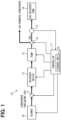
- FIG. 1 shows a configuration of a carbon dioxide recovery system 10 according to the present embodiment.
- the carbon dioxide recovery system 10 shown in FIG. 1 includes a channel open/close valve 11, a recovery device 12, a pump 13, a channel switching valve 14, a sensor 15, a CO 2 recovery tank 16, a controller 17, and a blower 19.
- An open-closed state of the channel open/close valve 11 is controlled by the controller 17.
- a mixed gas containing carbon dioxide can be introduced into the recovery device 12 through a channel pipe communicating the outside (atmosphere) and the inside of the recovery device 12.
- the channel open/close valve 11 is closed, the channel pipe communicating the outside and the inside of the recovery device 12 is blocked, and the recovery device 12 is sealed from the outside.
- the blower 19 is driven by the controller 17 when the channel open/close valve 11 is opened, and sends the mixed gas containing carbon dioxide into the recovery device 12 through the channel pipe communicating the outside and the inside of the recovery device 12.
- the blower 19 may be omitted.
- the pump 13 may also serve as the blower 19. That is, when the channel open/close valve 11 is opened, the pump 13 may be driven such that the mixed gas containing carbon dioxide is drawn into the recovery device 12 from the outside through the channel pipe.
- the recovery device 12 includes an electrochemical cell disposed inside a housing made of, for example, a metal.
- the electrochemical cell can adsorb carbon dioxide by an electrochemical reaction to separate the carbon dioxide from the mixed gas, and desorb the adsorbed carbon dioxide to accumulate the desorbed carbon dioxide in the CO 2 recovery tank 16 by the pump 13.
- the recovery device 12 has two openings. One of the openings is an introduction port for introducing the mixed gas containing carbon dioxide into the housing of the recovery device 12 from the outside.
- the other of the openings is a discharge port for discharging the mixed gas from which the carbon dioxide has been removed or the carbon dioxide desorbed from the electrochemical cell.
- the above channel pipe communicating the outside and the inside of the recovery device 12 is connected to the introduction port, and a channel pipe provided with the pump 13 is connected to the discharge port. Note that the inside of the recovery device 12 is the same as the inside of the housing.
- a plurality of electrochemical cells are stacked and disposed in the housing of the recovery device 12.
- the stacking direction of the plurality of electrochemical cells is a direction orthogonal to the flow direction of the mixed gas.
- Each electrochemical cell is formed in a plate shape, and is disposed such that a plate surface intersects with the stacking direction of the cells.
- a predetermined gap is provided between the adjacent electrochemical cells. The gap provided between the adjacent electrochemical cells serves as a gas channel through which the mixed gas flows.
- Each electrochemical cell is configured by stacking, for example, a working electrode current collecting layer, a working electrode, a separator, a counter electrode, a counter electrode current collecting layer, and the like in the described order.
- the working electrode is a negative electrode
- the counter electrode paired with the working electrode is a positive electrode.
- electrons can be provided to the working electrode so that a carbon dioxide adsorbent of the working electrode is caused to adsorb carbon dioxide, or electrons can be released from the working electrode so that the carbon dioxide adsorbent is caused to desorb the adsorbed carbon dioxide.
- the carbon dioxide adsorbent corresponds to an adsorbent.
- the working electrode current collecting layer is made of a porous conductive material having pores through which the mixed gas containing carbon dioxide can pass.
- the working electrode current collecting layer only needs to have gas permeability and conductivity, and as a material for forming the working electrode current collecting layer, for example, a metal material or a carbonaceous material can be used.
- the working electrode is formed of a material obtained by mixing the carbon dioxide adsorbent, a conductive substance, a binder, and the like.
- the carbon dioxide adsorbent has a property of adsorbing carbon dioxide by receiving electrons and desorbing the adsorbed carbon dioxide by releasing electrons.
- As the carbon dioxide adsorbent for example, polyanthraquinone can be used.
- the conductive substance forms a conductive path to the carbon dioxide adsorbent.
- a carbon material such as a carbon nanotube, carbon black, or graphene, can be used.
- the binder is for holding the carbon dioxide adsorbent and the conductive substance.
- a conductive resin can be used.
- a fluororesin such as polytetrafluoroethylene (PTFE) or polyvinylidene fluoride (PVDF), or the like can be used.
- PTFE polytetrafluoroethylene
- PVDF polyvinylidene fluoride
- the counter electrode is formed of a material obtained by mixing an electroactive auxiliary material, a conductive substance, a binder, and the like. Since the conductive substance and the binder of the counter electrode are similar to the conductive substance and the binder of the working electrode, description thereof is omitted.
- the electroactive auxiliary material of the counter electrode is made of a material having an active substance serving as an electron donor.
- the electroactive auxiliary material of the counter electrode is an auxiliary electroactive species that exchanges electrons with the carbon dioxide adsorbent of the working electrode.
- the electroactive auxiliary material for example, a metal complex capable of exchanging electrons by changing the valence of a metal ion can be used.
- the counter electrode current collecting layer is formed of a conductive material such as a metal material or a carbonaceous material.
- the separator is disposed between the working electrode and the counter electrode to separate the working electrode and the counter electrode.
- the separator is an insulating ion permeable membrane that prevents physical contact between the working electrode and the counter electrode to suppress an electrical short circuit, and causes ions to pass therethrough.
- a cellulose membrane, a polymer, a composite material of a polymer and a ceramic, or the like can be used.
- an electrolyte is provided across the working electrode and the counter electrode.
- an ionic liquid can be used as the electrolyte.
- the ionic liquid is a liquid salt that is non-volatile under normal temperature and pressure.
- the pump 13 sucks the residual mixed gas left in the recovery device 12 from the recovery device 12 and discharges the mixed gas to the outside (i.e., scavenges the residual mixed gas in the recovery device 12). And, when the carbon dioxide adsorbed by the carbon dioxide adsorbent is desorbed, the pump 13 sucks the desorbed carbon dioxide from the recovery device 12 and discharges the carbon dioxide toward the CO 2 recovery tank 16.
- the channel open/close valve 11 blocks the channel pipe communicating the outside and the inside of the recovery device 12. Therefore, the scavenging of the residual mixed gas in the recovery device 12 is performed by evacuation by the pump 13.
- the subsequent discharge of the carbon dioxide to the CO 2 recovery tank 16 is also performed in a state closer to a vacuum than the atmosphere.
- the channel switching valve 14 is a three-way valve that switches the channel for a gas flowing through the pipe on the downstream side of the pump 13. Switching the channel of the channel switching valve 14 is controlled by the controller 17. Specifically, when the mixed gas containing carbon dioxide is introduced into the recovery device 12 and when the residual mixed gas in the recovery device 12 is scavenged by the pump 13, the controller 17 controls the channel switching valve 14 such that the pipe on the downstream side of the pump 13 communicates with the outside (atmosphere). As a result, the mixed gas from which the carbon dioxide has been removed and the residual mixed gas in the recovery device 12 are released to the outside.
- the controller 17 controls the channel open/close valve 11 such that the pipe on the downstream side of the pump 13 communicates with the CO 2 recovery tank 16 side.
- the carbon dioxide recovered by the recovery device 12 can be accumulated in the CO 2 recovery tank 16.
- the sensor 15 detects the carbon dioxide concentration and the flow rate of the gas flowing through the pipe connected to the CO 2 recovery tank 16 at predetermined time intervals.
- the controller 17 can calculate (detect), from the carbon dioxide concentration and the flow rate detected by the sensor 15, the recovery amount of the carbon dioxide recovered in the CO 2 recovery tank 16. This carbon dioxide recovery amount corresponds to a detection result through the sensor.
- the carbon dioxide recovery amount may be calculated by the sensor 15. In this case, the sensor 15 outputs the carbon dioxide recovery amount to the controller 17.
- the carbon dioxide recovery amount can also be said to be a carbon dioxide monitor value.
- the carbon dioxide recovery amount corresponds to a recovery amount.
- the controller 17 includes a known microcomputer including a CPU, a ROM, a RAM, and the like, and peripheral devices thereof.
- the peripheral devices include a storage unit 18 having a storage medium.
- the storage unit 18 stores adsorption amount change map data and recovery amount change map data.
- the adsorption amount change map data corresponds to adsorption-amount change data.
- the recovery amount change map data corresponds to recovery-amount change data.
- an adsorption time period is associated with a target carbon dioxide adsorption amount, as shown in FIG. 5 .
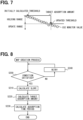
- a change in the carbon dioxide recovery amount is associated with the target carbon dioxide adsorption amount, as shown in FIGS. 6 and 7 .
- the target carbon dioxide adsorption amount is also referred to as a maximum adsorption amount.
- the adsorption time period is also referred to as an adsorption mode execution time period.
- the adsorption amount change map data and the recovery amount change map data will be described in detail later.
- the controller 17 performs various arithmetic processing on the basis of a control program stored in the storage medium such as a ROM, and controls operations of various control target devices such as the channel open/close valve 11, the recovery device 12, the pump 13, the channel switching valve 14, and the blower 19.
- the controller 17 of the present embodiment controls the operations of the various control target devices such that, in the carbon dioxide recovery system 10, a series of control sequences for carbon dioxide recovery, including at least an adsorption mode and a desorption/recovery mode, is executed.
- the control sequences may include a scavenging mode in addition to the above.
- the desorption/recovery mode indicates that a desorption mode and a recovery mode are defined as one mode.
- FIG. 2 is a flowchart showing a process performed in the controller 17 to execute the control sequences.
- FIG. 3 is a time chart showing operation of each unit when the process shown in the flowchart of FIG. 2 is performed.
- FIGS. 4 are explanatory views for explaining the adsorption mode, the scavenging mode, and the desorption/recovery mode included in the series of control sequences.
- the controller 17 first starts, in a step S100, the adsorption mode that is the first operation mode of the series of control sequences.
- the channel open/close valve 11 is opened such that the mixed gas containing carbon dioxide can be introduced into the recovery device 12, as shown in FIG. 3 .
- the blower 19 is driven such that more mixed gas is introduced into the recovery device 12.
- the pump 13 also serves as the blower 19
- the pump 13 is driven to suck the mixed gas, so that the mixed gas is drawn into the recovery device 12 from the outside.
- the pump 13 is driven only to suck the mixed gas from the outside, so that the energy required for the suction is less than that required for pump drive for the evacuation in the scavenging mode or the desorption/recovery mode to be described later.
- an adsorption potential (corresponding to a first potential), at which the carbon dioxide adsorbent of the working electrode can adsorb carbon dioxide, is applied between the working electrode and the counter electrode of the electrochemical cell of the recovery device 12, as shown in FIG. 3 .
- the channel switching valve 14 is controlled such that the pipe on the downstream side of the pump 13 communicates with the outside, as shown in FIG. 3 .
- the mixed gas (atmospheric gas) containing carbon dioxide passes through the channel open/close valve 11 and enters the recovery device 12 in the adsorption mode, as shown by a dotted arrow in FIG. 4A .
- the carbon dioxide in the mixed gas that has entered the recovery device 12 is adsorbed by the plurality of the electrochemical cells, whereby carbon dioxide is removed from the mixed gas.
- the mixed gas, from which the carbon dioxide has been removed, passes through the pump 13, is guided to a channel pipe leading toward the outside at the channel switching valve 14, and is discharged to the outside through the channel pipe.
- the controller 17 determines whether the adsorption mode execution time period has elapsed.
- the adsorption mode execution time period is not constant but changes for the reasons: for estimating, in the later-described map creation process, a maximum adsorption amount of the electrochemical cell and a maximum adsorption amount time period that is the adsorption mode execution time period to obtain the maximum adsorption amount; for optimizing the carbon dioxide recovery amount and consumed energy if the carbon dioxide adsorption performance of the electrochemical cell changes due to environmental changes or deterioration over time; and for others.
- This changing adsorption mode execution time period is set by the controller 17.
- the maximum adsorption amount is used as the target carbon dioxide adsorption amount. Therefore, the maximum adsorption amount is also referred to as the target carbon dioxide adsorption amount in the following description.
- the maximum adsorption amount corresponds to the target adsorption amount.
- the process proceeds to a step S120.
- the determination processing in the step S110 is repeatedly executed until the adsorption mode execution time period elapses.
- adsorption mode end processing is executed. Specifically, the controller 17 closes the channel open/close valve 11 to block the mixed gas that will flow into the recovery device 12 from the outside. In the case where the blower 19 is provided, the controller 17 stops the driving of the blower 19. The controller 17 also resets a count value of a counter that counts the adsorption mode execution time period, and the like.
- the controller 17 applies the adsorption potential during the execution of the adsorption mode in which carbon dioxide is adsorbed, so that the carbon dioxide adsorbent adsorbs carbon dioxide.
- the controller 17 applies the adsorption potential only during the adsorption mode execution time period corresponding to the target carbon dioxide adsorption amount.
- the adsorption mode execution time period can be obtained from the adsorption amount change map data.
- the target carbon dioxide adsorption amount can be obtained from the recovery amount change map data.
- the controller 17 acquires, from the recovery amount change map data, the target carbon dioxide adsorption amount associated with the carbon dioxide recovery amount detected through the sensor 15. As shown in FIG. 7 , the target carbon dioxide adsorption amount in the recovery amount change map data is a correlation value correlated with the carbon dioxide recovery amount detected through the sensor 15. Therefore, it can be said that the controller 17 acquires, as the target carbon dioxide adsorption amount, a correlation value correlated with the carbon dioxide recovery amount detected through the sensor 15.
- the controller 17 acquires the adsorption mode execution time period associated with the target carbon dioxide adsorption amount from the adsorption amount change map data.
- the adsorption mode execution time period is 80 [s].
- the target carbon dioxide adsorption amount is updated according to the carbon dioxide recovery amount detected through the sensor 15. As shown in FIG. 5 , the adsorption mode execution time period changes every time the target carbon dioxide adsorption amount is updated.
- the target carbon dioxide adsorption amount may be stored in the storage unit 18 or the like as an initially calculated threshold value or an updated threshold value.
- a step S130 the controller 17 starts the scavenging mode that is the second operation mode of the series of control sequences.
- the channel open/close valve 11 remains closed, as shown in FIG. 3 .
- the adsorption potential applied between the working electrode and the counter electrode of the electrochemical cell of the recovery device 12 is maintained as it is.
- the communication between the pipe on the downstream side of the pump 13 and the outside by the channel switching valve 14 is also maintained.
- the scavenging mode driving of the pump 13 is started as shown in FIG. 3 .
- the channel open/close valve 11 is closed, so that the recovery device 12 is in a sealed state on the upstream side of the pump 13.
- the pump 13 is driven in this state, the residual mixed gas left in the sealed recovery device 12, from which the carbon dioxide has been removed, is sucked from the inside of the recovery device 12 and discharged to the outside.
- the residual mixed gas in the recovery device 12 can be scavenged.
- the adsorption potential is applied.
- the recovery device 12 on the upstream side of the pump 13 is sealed, the scavenging of the residual mixed gas in the recovery device 12 is performed by evacuation by the pump 13. Therefore, for example, in the case where the pump 13 also serves as the blower 19, the driving of the pump 13 is continued, but the drive output thereof is made higher than that in an intake mode by the start of the scavenging mode.
- the electrochemical cell of the recovery device 12, the pump 13, and the channel switching valve 14 in the scavenging mode, the residual mixed gas in the recovery device 12, from which the carbon dioxide has been removed, passes through the pump 13, is guided to the channel pipe leading toward the outside at the channel switching valve 14, and is discharged to the outside through the channel pipe, as shown by a dotted arrow in FIG. 4B .
- the controller 17 determines whether a scavenging mode execution time period has elapsed.
- the scavenging mode execution time period is predetermined to a time period sufficient to scavenge the residual mixed gas in the recovery device 12.
- the process proceeds to a step S150.
- the determination processing in the step S140 is repeatedly executed until the scavenging mode execution time period elapses.
- step S150 scavenging mode end processing is executed. Specifically, the controller 17 resets a count value of a counter that counts the scavenging mode execution time period, and the like.
- a step S160 the controller 17 starts the desorption/recovery mode that is the third operation mode of the series of control sequences.
- the channel open/close valve 11 is maintained in a closed state, as shown in FIG. 3 .
- the pump 13 sucks the carbon dioxide desorbed from the electrochemical cell in a state closer to a vacuum than the atmosphere, so that the driving by the drive output equivalent to that in the scavenging mode is continued.
- a desorption potential (corresponding to a second potential), at which the carbon dioxide adsorbed by the carbon dioxide adsorbent of the working electrode can be desorbed by releasing electrons from the working electrode, is applied between the working electrode and the counter electrode of the electrochemical cell of the recovery device 12. Furthermore, in the desorption/recovery mode, the channel switching valve 14 is controlled to cause the pipe on the downstream side of the pump 13 to communicate with the CO 2 recovery tank 16, as shown in FIG. 3 .
- the controller 17 can calculate the recovery amount of the carbon dioxide recovered in the CO 2 recovery tank 16 by executing the series of control sequences.
- concentration of the carbon dioxide flowing through the channel pipe toward the CO 2 recovery tank 16 is usually close to 100%. Therefore, a sensor 15 capable of detecting a flow rate of carbon dioxide may be used.
- the desorption/recovery mode instead of simultaneous performing of the desorption/recovery of the carbon dioxide, priority may be given to the desorption of the carbon dioxide from the electrochemical cell, and after a predetermined time period has elapsed from the desorption of the carbon dioxide, the recovery of the desorbed carbon dioxide may be started. That is, by separating the desorption mode and the recovery mode and delaying the execution start time of the recovery mode from the execution start time of the desorption mode, the execution time period of the recovery mode may be shortened from the execution time period of the desorption mode. In this case, the driving of the pump 13 is temporarily stopped at the start of the desorption mode.
- the desorption potential is applied between the working electrode and the counter electrode of the electrochemical cell to desorb carbon dioxide from the carbon dioxide adsorbent of the working electrode.
- the recovery mode is started and the pump 13 is driven again.
- the pump 13 only needs to be driven in the recovery mode, so that the pump 13 can be efficiently driven.
- the desorption potential is applied between the working electrode and the counter electrode of the electrochemical cell, and the desorption of the carbon dioxide from the electrochemical cell is continued.
- a desorption/recovery mode execution time period or a recovery mode execution time period (hereinafter, it is described as a recovery mode execution time period) has elapsed.
- the recovery mode execution time period is not constant but changes for the reasons: for optimizing the carbon dioxide recovery amount and consumed energy if the carbon dioxide adsorption performance of the electrochemical cell changes due to environmental changes or deterioration over time; and for others.
- the changing recovery mode execution time period is set by the controller 17.
- step S170 When it is determined in the determination processing in the step S170 that the set recovery mode execution time period has elapsed, the process proceeds to step a S180. On the other hand, when it is determined that the set recovery mode execution time period has not elapsed, the determination processing in the step S170 is repeatedly executed until the recovery mode execution time period elapses. As described above, the controller 17 applies the desorption potential during the execution of the recovery mode in which carbon dioxide is recovered, so that the carbon dioxide adsorbed by the carbon dioxide adsorbent is desorbed. Then, the controller 17 applies the desorption potential only during the recovery mode execution time period corresponding to the target carbon dioxide adsorption amount. The recovery mode execution time period corresponds to a recovery time period.
- step S180 recovery mode end processing is executed.
- the controller 17 opens the channel open/close valve 11 to cause the recovery device 12 to communicate with the outside.
- the controller 17 stops the application of the desorption potential to the electrochemical cell.
- the controller 17 stops the driving of the pump 13.
- the controller 17 switches the channel switching valve 14 to cause the pipe on the downstream side of the pump 13 to communicate with the outside.
- the controller 17 also resets a count value of a counter that counts the recovery mode execution time period, and the like.
- the carbon dioxide adsorption performance of the electrochemical cell changes due to deterioration over time or the like.
- an upper limit amount that the electrochemical cell can adsorb carbon dioxide cannot be directly detected. Therefore, it cannot be denied the possibility that the execution of the adsorption mode may be continued even though the carbon dioxide adsorption amount of the electrochemical cell reaches the upper limit, or the execution of the recovery mode may be continued even though the recovery of the carbon dioxide desorbed from the electrochemical cell is substantially finished.
- the adsorption mode is always executed for a time period sufficient to adsorb the upper limit amount of carbon dioxide that can be adsorbed by the electrochemical cell and the recovery mode is executed for a time period sufficient to recover all the carbon dioxide adsorbed by the electrochemical cell in order to maximize the recovery amount of carbon dioxide, there is the possibility that, in the carbon dioxide recovery system 10, excessive energy may be consumed with respect to the recovery amount of carbon dioxide.
- the carbon dioxide recovery system 10 has a configuration in which the adsorption amount change map data and the recovery amount change map data are stored in the storage unit 18 of the controller 17.
- the controller 17 When performing the map creation process, the controller 17 causes multiple times of the adsorption mode to be executed at different adsorption mode execution time periods (elapsed time periods), and detects, through the sensor 15, the carbon dioxide recovery amounts in multiple times of the recovery mode executed corresponding to each adsorption mode.
- FIG. 3 shows an example in which three times of adsorption mode are executed at different adsorption mode execution time periods. The number of times of execution of the multiple times of the adsorption mode may be two.
- the execution time period of the first adsorption mode is set to be relatively short such that the carbon dioxide adsorption amount of the electrochemical cell does not reach the upper limit value. Therefore, the carbon dioxide recovery amount, detected when the recovery mode corresponding to the first adsorption mode is executed, is an amount less than the upper limit value of the carbon dioxide adsorption amount of the electrochemical cell.
- the execution time period of the second adsorption mode is set to be relatively long such that the carbon dioxide adsorption amount of the electrochemical cell reaches substantially the upper limit value. Therefore, the carbon dioxide recovery amount, detected when the recovery mode corresponding to the second adsorption mode is executed, is an amount substantially equal to the upper limit value of the carbon dioxide adsorption amount of the electrochemical cell.
- the execution time period of the third adsorption mode is set to be the longest such that, even after the carbon dioxide adsorption amount of the electrochemical cell reaches the upper limit value, the adsorption mode is executed for a certain period of time. Therefore, the carbon dioxide recovery amount, detected when the recovery mode corresponding to the third adsorption mode is executed, is an amount equal to the upper limit value of the carbon dioxide adsorption amount of the electrochemical cell.
- a maximum adsorption amount of the electrochemical cell and a maximum adsorption amount time period which is an adsorption mode execution time period to obtain the maximum adsorption amount.
- a map creation determination condition it is determined whether a map creation determination condition is satisfied.
- the map creation determination condition is satisfied when the carbon dioxide recovery amounts in the three recovery modes can be plotted for a single piece of the adsorption amount change map data, and a non-plotted maximum value of the carbon dioxide recovery amount exists on the same straight line.
- the same straight line may include a tolerance.
- step S240 retry is performed.
- the controller 17 causes the adsorption mode to be executed again, and detects, through the sensor 15, the carbon dioxide recovery amount in the recovery mode executed corresponding to the adsorption mode. At this time, the controller 17 sets the execution time period of the adsorption mode to be longer than the last time (third time).
- the controller 17 performs S200 using the carbon dioxide recovery amount obtained in the retry.
- the controller 17 repeatedly executes the steps S200 and S240 until YES is determined in the step S200.
- the controller 17 adopts, in a step S220, the carbon dioxide recovery amount at the time of the retry as the target carbon dioxide adsorption amount.
- FIG. 9A is a graph showing, based on the carbon dioxide recovery amount detected when the recovery mode corresponding to the first adsorption mode is executed, the carbon dioxide adsorption amount of the electrochemical cell and the execution time period of the first adsorption mode.
- the carbon dioxide adsorption amount of the electrochemical cell can be regarded as equal to the detected carbon dioxide recovery amount.
- the execution time period of the first adsorption mode is set to be relatively short such that the carbon dioxide adsorption amount of the electrochemical cell does not reach the upper limit value.
- an increasing gradient line can be determined, as shown in FIG. 9A .
- FIG. 9B is a graph showing, based on the carbon dioxide recovery amount detected when the recovery mode corresponding to each of the second and third adsorption modes is executed, the carbon dioxide adsorption amount of the each electrochemical cell and the execution time period of each of the second and third adsorption modes.
- the execution time period of the second adsorption mode is set to be relatively long such that the carbon dioxide adsorption amount of the electrochemical cell reaches substantially the upper limit value
- the execution time period of the third adsorption mode is set to be the longest such that, even after the carbon dioxide adsorption amount of the electrochemical cell reaches the upper limit value, the adsorption mode is executed for a certain period of time. Therefore, based on the carbon dioxide adsorption amount of the electrochemical cell when each of the second and third adsorption modes is executed, an upper limit line of the carbon dioxide adsorption amount of the electrochemical cell can be determined, as shown in FIG. 9B .
- the carbon dioxide adsorption amount corresponding to the upper limit line is the target carbon dioxide adsorption amount that is the maximum adsorption amount that can be adsorbed.
- the upper limit line of the carbon dioxide adsorption amount of the electrochemical cell may be determined based on the carbon dioxide adsorption amount of the electrochemical cell that can be obtained through the execution of one time of the adsorption mode and the recovery mode corresponding to the one time of the adsorption mode.
- the adsorption time period which is the maximum adsorption amount time period that is the adsorption mode execution time period corresponding to the maximum adsorption amount, can be determined from the intersection between the increasing gradient line in FIG. 9A and the upper limit line in FIG. 9B , as shown in FIG. 9C .
- the controller 17 creates, based on the carbon dioxide recovery amounts that are the detection results in the multiple times of the recovery mode, the adsorption-amount change data by estimating the maximum adsorption amount of the electrochemical cell as the target carbon dioxide adsorption amount and estimating the adsorption time period corresponding to the maximum adsorption amount. Then, the controller 17 stores the created adsorption amount change map data in the storage unit 18. In the adsorption amount change map data, the target carbon dioxide adsorption amount and the adsorption time period are updated due to deterioration over time or the like of the electrochemical cell.
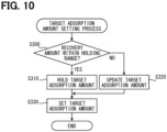
- the controller 17 executes the flowchart of FIG. 10 to determine whether the target carbon dioxide adsorption amount is maintained to the current value or updated.
- the recovery amount change map data a different target carbon dioxide adsorption amount is associated every number of cycles of multiple times of the control sequences, as shown in FIGS. 6 and 7 .
- the target carbon dioxide adsorption amount is updated every 10 cycles.
- the carbon dioxide recovery amount (carbon dioxide monitor value) detected through the sensor 15 is associated with the target carbon dioxide adsorption amount.
- the initially calculated threshold value is an initial target carbon dioxide adsorption amount adopted from the first cycle to the 10th cycle.
- the updated threshold value is an updated target carbon dioxide adsorption amount.
- the updated threshold value is a target carbon dioxide adsorption amount assumed due to deterioration over time or the like of the electrochemical cell. Therefore, the updated threshold value is a value smaller than the initially calculated threshold value. In addition, the updated threshold value becomes a smaller value as the number of the cycles increases.
- adsorption amount holding ranges are between the initially calculated threshold value and the updated threshold value and between the updated threshold value and the next updated threshold value.
- the adsorption amount holding range is a range where the current target carbon dioxide adsorption amount is held.
- a range out of the adsorption amount holding range is an adsorption amount update range.
- the adsorption amount update range is a range where the target carbon dioxide adsorption amount is updated from the current value.
- a step S300 it is determined whether the recovery amount is within the adsorption amount holding range.
- the controller 17 determines whether the carbon dioxide monitor value as the recovery amount is within the adsorption amount holding range. When the controller 17 determines that the carbon dioxide monitor value is within the adsorption amount holding range, the process proceeds to a step S310. When the controller 17 determines that the carbon dioxide monitor value is not within the adsorption amount holding range, the process proceeds to a step S320.
- the target carbon dioxide adsorption amount is held.
- the controller 17 holds the current target carbon dioxide adsorption amount. In the case of the carbon dioxide monitor value indicated by dot hatching in FIG. 7 , the controller 17 holds the current target carbon dioxide adsorption amount.
- the target carbon dioxide adsorption amount is updated.
- the controller 17 updates the current target carbon dioxide adsorption amount to a new target carbon dioxide adsorption amount. In the case of the carbon dioxide monitor value indicated by diagonal hatching in FIG. 7 , the controller 17 updates the target carbon dioxide adsorption amount.
- a target carbon dioxide adsorption amount is set.
- the controller 17 sets the current target carbon dioxide adsorption amount or the updated target carbon dioxide adsorption amount as the target carbon dioxide adsorption amount when the adsorption mode execution time period is set. As described above, the controller 17 sets the target carbon dioxide adsorption amount from the carbon dioxide recovery amount.
- the carbon dioxide recovery system 10 includes the controller 17 that detects, through the sensor 15, the recovery amount of the carbon dioxide recovered from the recovery device 12 to the CO 2 recovery tank 16. Then, the controller 17 acquires, as the target carbon dioxide adsorption amount, a correlation value correlated with the carbon dioxide recovery amount as a detection result through the sensor 15. Therefore, the carbon dioxide recovery system 10 can grasp the target carbon dioxide adsorption amount.
- the controller 17 causes multiple times of the adsorption mode to be executed, and grasps the target carbon dioxide adsorption amount using the adsorption amount change map data created using the carbon dioxide recovery amounts detected through the sensor 15 in multiple times of the recovery mode executed corresponding to each adsorption mode. Then, the controller 17 applies the adsorption potential only during the adsorption mode execution time period obtained from the adsorption amount change map data. Therefore, the controller 17 can apply the adsorption potential only for a time period required to obtain the maximum adsorption amount. In other words, the controller 17 can suppress application of the adsorption potential for a time period longer than the time period required to obtain the maximum adsorption amount. Therefore, the controller 17 can appropriately control the application time period of the adsorption potential to obtain the maximum adsorption amount.
- controller 17 Since the controller 17 updates the adsorption amount change map data according to the carbon dioxide recovery amount detected through the sensor 15, it is possible to grasp the optimum target carbon dioxide adsorption amount and appropriately control the application time period of the adsorption potential even if the electrochemical cell deteriorates over time.
- the adsorption mode execution time period is not limited to that obtained from the adsorption amount change map data.
- the adsorption mode execution time period can also be obtained by calculating a predetermined relational expression.
- the controller 17 may obtain the adsorption mode execution time period by multiplying the carbon dioxide recovery amount [g] detected through the sensor 15 by a carbon dioxide adsorption coefficient [s/g].
- the carbon dioxide adsorption coefficient is a coefficient indicated by a time period required for the carbon dioxide adsorbent to adsorb a predetermined amount of carbon dioxide. That is, the carbon dioxide adsorption coefficient is defined as a time period required to adsorb 1 [g] of carbon dioxide.
- the carbon dioxide adsorption coefficient [s/g] is adsorption time period [s]/carbon dioxide adsorption amount [g].
- the first modification can achieve the same effects as those of the above embodiment.
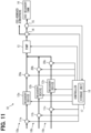
- the carbon dioxide recovery system 10 may include a plurality of recovery devices 12a to 12c, and the plurality of recovery devices 12a to 12c may be connected in parallel for the CO 2 recovery tank 16. That is, the carbon dioxide recovery system 10 may include a plurality of subsystems 10a to 10c. Each of the subsystems 10a to 10c includes one of the recovery devices 12a to 12c.
- the subsystem 10a includes a channel open/close valve 11a and a switching valve 20a in addition to the recovery device 12a.
- the subsystem 10b includes a channel open/close valve 11b and a switching valve 20b in addition to the recovery device 12b.
- the subsystem 10c includes a channel open/close valve 11c and a switching valve 20c in addition to the recovery device 12c. Note that, here, an example including the three subsystems 10a to 10c is adopted as an example. However, the carbon dioxide recovery system 10 may include two subsystems or four or more subsystems.
- the controller 17 can execute an individual mode (i.e. individual recovery mode) in which carbon dioxide is recovered individually from the electrochemical cell of each of the plurality of recovery devices 12a to 12c and execute a simultaneous mode (i.e. simultaneous recovery mode) in which carbon dioxide is recovered simultaneously from the respective electrochemical cells of at least two or more of the recovery devices.
- an individual mode i.e. individual recovery mode
- a simultaneous mode i.e. simultaneous recovery mode
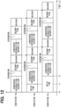
- the controller 17 causes a series of control sequences, including the adsorption mode and the recovery mode targeting each electrochemical cell of each of the recovery devices 12a to 12c, to be started at different times, as shown in FIG. 12 .
- a timing to is defined, for example, as a start timing of the carbon dioxide recovery system 10.
- the controller 17 starts the control sequences in the subsystem 10a at the timing t0.
- the controller 17 starts the control sequences in the subsystem 10b at a timing t1 when a predetermined time period has elapsed from the timing t0.
- the controller 17 starts the control sequences in the subsystem 10c at a timing t2 when a predetermined time period has elapsed from the timing t1.
- a delay time period occurs during which each of the subsystems 10a to 10c does not execute the control sequences.
- the period between the timing to and the timing t1 is the delay time period.
- the period between the timing to and the timing t2 is the delay time period.
- the delay time period corresponds to a period during which the control sequences are not executed. Therefore, the controller 17 causes, during the delay time period, the adsorption mode and the recovery mode for estimating the maximum adsorption amount to be executed.
- the carbon dioxide recovery system 10 can effectively utilize the delay time period.
- each adsorption mode may be performed in the different subsystems 10a to 10c during the map creating process.
- the controller 17 causes a series of the control sequences, including the adsorption mode and the recovery mode targeting each electrochemical cell of each of the recovery devices 12a to 12c, to be started at the same time.
- the control sequences are started simultaneously, for example, at the timing t0. Therefore, no delay time period occurs in the simultaneous mode.
- controller 17 may switch between the individual mode and the simultaneous mode according to a situation.
- the controller 17 switches the mode for the purpose of shortening the creation time period of the adsorption amount change map data, or the like.
- Examples of the situation include: an initial operation of the carbon dioxide recovery system 10 (at the time of installation of equipment); a periodic state transition, from a dormant state to an operating state, of the carbon dioxide recovery system 10; periodic maintenance; return from a failure of the carbon dioxide recovery system 10; return from an external environmental abnormality of the carbon dioxide recovery system 10; and the like.
- periodic maintenance the following situations are considered in which: no electrochemical cell is replaced; some electrochemical cells are replaced; and all electrochemical cells are replaced.
- the external environmental abnormality is a power failure or the like.
- the controller 17 executes the individual mode at the time of the installation of equipment and at the time of the return from a failure, and executes the simultaneous mode at the time of the state transition from a dormant state to an operating state and at the time of the return from the external environmental abnormality. In addition, the controller 17 executes the simultaneous mode when no electrochemical cell is replaced and when some electrochemical cells are replaced, and executes the individual mode when all electrochemical cells are replaced.
- the controller 17 may use common adsorption amount change map data for the subsystems 10a to 10c.
- the controller 17 may use individual adsorption amount change map data for each of the subsystems 10a to 10c.
- the carbon dioxide recovery system 10 may be configured to be able to execute only one of the individual mode and the simultaneous mode.
Landscapes
- Chemical & Material Sciences (AREA)
- Engineering & Computer Science (AREA)
- Analytical Chemistry (AREA)
- General Chemical & Material Sciences (AREA)
- Oil, Petroleum & Natural Gas (AREA)
- Chemical Kinetics & Catalysis (AREA)
- Health & Medical Sciences (AREA)
- Biomedical Technology (AREA)
- Environmental & Geological Engineering (AREA)
- Electrochemistry (AREA)
- Electrolytic Production Of Non-Metals, Compounds, Apparatuses Therefor (AREA)
- Treating Waste Gases (AREA)
- Carbon And Carbon Compounds (AREA)
Abstract
Description
- The present disclosure relates to a carbon dioxide recovery system that recovers carbon dioxide from a mixed gas containing carbon dioxide.
- Patent Literature 1 (
JP 2018-533470 A - In a carbon dioxide recovery system using an electrochemical cell, an adsorption potential is applied to the electrochemical cell in order to cause the electrochemical cell to adsorb carbon dioxide. In addition, in the carbon dioxide recovery system, in order to reduce an energy loss during adsorption, an application time period of the adsorption potential for obtaining a target adsorption amount may be appropriately controlled with an adsorption amount that can be adsorbed by the electrochemical cell as the target adsorption amount.
- In order to appropriately control the application time period of the adsorption potential, it is necessary to grasp the adsorption amount that can be adsorbed by the electrochemical cell. The adsorption amount that can be adsorbed can be grasped, for example, by detecting the concentration of carbon dioxide in the atmosphere. However, it has been difficult to grasp the adsorption amount for reasons such as a relatively low concentration of carbon dioxide in the atmosphere.
- The present disclosure has been made in view of the above points, and an object thereof is to provide a carbon dioxide recovery system capable of grasping an adsorption amount of carbon dioxide that can be adsorbed by an electrochemical cell.
- According to an aspect of the present disclosure, a carbon dioxide recovery system recovers carbon dioxide from a mixed gas containing carbon dioxide by an electrochemical reaction. The carbon dioxide recovery system includes a carbon dioxide recovery tank, a recovery device, a sensor and a controller. The carbon dioxide recovery tank stores recovered carbon dioxide. The recovery device includes a housing into which the mixed gas is supplied, and an electrochemical cell housed in the housing. The electrochemical cell includes a working electrode having an adsorbent capable of adsorbing carbon dioxide, and a counter electrode paired with the working electrode. The sensor detects a recovery amount that is an amount of carbon dioxide recovered in the recovery device and sent to the carbon dioxide recovery tank. The controller executes an adsorption mode in which carbon dioxide is adsorbed and a recovery mode in which carbon dioxide is recovered. The controller is configured to apply a first potential between the working electrode and the counter electrode only for an adsorption time period in the adsorption mode such that the adsorbent adsorbs carbon dioxide. The adsorption time period corresponds to a target adsorption amount that is an amount of carbon dioxide that can be adsorbed by the adsorbent. The controller is configured to apply a second potential between the working electrode and the counter electrode only for a recovery time period in the recovery mode such that the carbon dioxide adsorbed by the adsorbent is desorbed. The controller is configured to acquire the target adsorption amount as a correlation value correlated with the recovery amount that is a detection result of the sensor.
- As described above, the carbon dioxide recovery system according to the present disclosure includes the controller that detects, through the sensor, the recovery amount of the carbon dioxide recovered in the recovery device and sent to the carbon dioxide recovery tank. Then, the controller acquires the detected recovery amount, and acquires the target adsorption amount as the correlation value correlated with the detected recovery amount. Therefore, the carbon dioxide recovery system can grasp the target adsorption amount of carbon dioxide by the electrochemical cell.
-
-
FIG. 1 is a view showing a configuration of a carbon dioxide recovery system according to an embodiment. -
FIG. 2 is a flowchart showing a process in a controller to execute a series of control sequences for carbon dioxide recovery. -
FIG. 3 is a time chart showing operation of each unit when the process shown in the flowchart ofFIG. 2 is performed. -
FIG. 4A is an explanatory view for explaining an adsorption mode included in a series of control sequences. -
FIG. 4B is an explanatory view for explaining a scavenging mode included in the series of control sequences. -
FIG. 4C is an explanatory view for explaining a desorption/recovery mode included in the series of control sequences. -
FIG. 5 is a graph showing an example of adsorption amount change map data. -
FIG. 6 is a graph showing an example of recovery amount change map data. -
FIG. 7 is an enlarged graph of a portion VII inFIG. 6 . -
FIG. 8 is a flowchart showing a map creation process for creating the adsorption amount change map data. -
FIG. 9A is an explanatory graph for determining an increasing gradient line in estimation of a maximum adsorption amount of an electrochemical cell and a maximum adsorption amount time period. -
FIG. 9B is an explanatory graph for determining an upper limit line of an carbon dioxide adsorption amount in the estimation. -
FIG. 9C is an explanatory graph for determining an intersection between the increasing gradient line and the upper limit line in the estimation. -
FIG. 10 is a flowchart showing a setting process for a target carbon dioxide adsorption amount. -
FIG. 11 is a view showing a configuration of a carbon dioxide recovery system according to a modification. -
FIG. 12 is a time chart showing control sequences of the carbon dioxide recovery system according to the modification. - Hereinafter, multiple embodiments for implementing the present disclosure will be described referring to drawings. In the respective embodiments, a part that corresponds to a matter described in a preceding embodiment may be assigned the same reference numeral, and redundant explanation for the part may be omitted. When only a part of a configuration is described in an embodiment, another preceding embodiment may be applied to the other parts of the configuration. The parts may be combined even if it is not explicitly described that the parts can be combined. The embodiments may be partially combined even if it is not explicitly described that the embodiments can be combined, provided there is no harm in the combination.
- Hereinafter, a carbon dioxide recovery system according to an embodiment of the present disclosure will be described in detail with reference to the drawings. In the drawings, the same or equivalent portions are denoted by the same reference numerals. The carbon dioxide recovery system according to the present embodiment recovers carbon dioxide from a mixed gas (e.g., atmospheric gas) containing carbon dioxide. The mixed gas from which the carbon dioxide has been removed is discharged to the outside (atmosphere).
FIG. 1 shows a configuration of a carbondioxide recovery system 10 according to the present embodiment. - The carbon
dioxide recovery system 10 shown inFIG. 1 includes a channel open/close valve 11, arecovery device 12, apump 13, achannel switching valve 14, asensor 15, a CO2 recovery tank 16, acontroller 17, and ablower 19. - An open-closed state of the channel open/
close valve 11 is controlled by thecontroller 17. When the channel open/close valve 11 is opened, a mixed gas containing carbon dioxide can be introduced into therecovery device 12 through a channel pipe communicating the outside (atmosphere) and the inside of therecovery device 12. On the other hand, when the channel open/close valve 11 is closed, the channel pipe communicating the outside and the inside of therecovery device 12 is blocked, and therecovery device 12 is sealed from the outside. - The
blower 19 is driven by thecontroller 17 when the channel open/close valve 11 is opened, and sends the mixed gas containing carbon dioxide into therecovery device 12 through the channel pipe communicating the outside and the inside of therecovery device 12. However, theblower 19 may be omitted. Alternatively, thepump 13 may also serve as theblower 19. That is, when the channel open/close valve 11 is opened, thepump 13 may be driven such that the mixed gas containing carbon dioxide is drawn into therecovery device 12 from the outside through the channel pipe. - The
recovery device 12 includes an electrochemical cell disposed inside a housing made of, for example, a metal. The electrochemical cell can adsorb carbon dioxide by an electrochemical reaction to separate the carbon dioxide from the mixed gas, and desorb the adsorbed carbon dioxide to accumulate the desorbed carbon dioxide in the CO2 recovery tank 16 by thepump 13. Therecovery device 12 has two openings. One of the openings is an introduction port for introducing the mixed gas containing carbon dioxide into the housing of therecovery device 12 from the outside. The other of the openings is a discharge port for discharging the mixed gas from which the carbon dioxide has been removed or the carbon dioxide desorbed from the electrochemical cell. The above channel pipe communicating the outside and the inside of therecovery device 12 is connected to the introduction port, and a channel pipe provided with thepump 13 is connected to the discharge port. Note that the inside of therecovery device 12 is the same as the inside of the housing. - A plurality of electrochemical cells are stacked and disposed in the housing of the
recovery device 12. The stacking direction of the plurality of electrochemical cells is a direction orthogonal to the flow direction of the mixed gas. Each electrochemical cell is formed in a plate shape, and is disposed such that a plate surface intersects with the stacking direction of the cells. A predetermined gap is provided between the adjacent electrochemical cells. The gap provided between the adjacent electrochemical cells serves as a gas channel through which the mixed gas flows. - Each electrochemical cell is configured by stacking, for example, a working electrode current collecting layer, a working electrode, a separator, a counter electrode, a counter electrode current collecting layer, and the like in the described order. The working electrode is a negative electrode, and the counter electrode paired with the working electrode is a positive electrode. By changing a potential difference to be applied between the working electrode and the counter electrode, electrons can be provided to the working electrode so that a carbon dioxide adsorbent of the working electrode is caused to adsorb carbon dioxide, or electrons can be released from the working electrode so that the carbon dioxide adsorbent is caused to desorb the adsorbed carbon dioxide. The carbon dioxide adsorbent corresponds to an adsorbent.
- The working electrode current collecting layer is made of a porous conductive material having pores through which the mixed gas containing carbon dioxide can pass. The working electrode current collecting layer only needs to have gas permeability and conductivity, and as a material for forming the working electrode current collecting layer, for example, a metal material or a carbonaceous material can be used.
- The working electrode is formed of a material obtained by mixing the carbon dioxide adsorbent, a conductive substance, a binder, and the like. The carbon dioxide adsorbent has a property of adsorbing carbon dioxide by receiving electrons and desorbing the adsorbed carbon dioxide by releasing electrons. As the carbon dioxide adsorbent, for example, polyanthraquinone can be used. The conductive substance forms a conductive path to the carbon dioxide adsorbent. As the conductive substance, for example, a carbon material, such as a carbon nanotube, carbon black, or graphene, can be used. The binder is for holding the carbon dioxide adsorbent and the conductive substance. As the binder, for example, a conductive resin can be used. As the conductive resin, for example, an epoxy resin containing Ag or the like as a conductive filler, a fluororesin such as polytetrafluoroethylene (PTFE) or polyvinylidene fluoride (PVDF), or the like can be used.
- The counter electrode is formed of a material obtained by mixing an electroactive auxiliary material, a conductive substance, a binder, and the like. Since the conductive substance and the binder of the counter electrode are similar to the conductive substance and the binder of the working electrode, description thereof is omitted. The electroactive auxiliary material of the counter electrode is made of a material having an active substance serving as an electron donor. The electroactive auxiliary material of the counter electrode is an auxiliary electroactive species that exchanges electrons with the carbon dioxide adsorbent of the working electrode. As the electroactive auxiliary material, for example, a metal complex capable of exchanging electrons by changing the valence of a metal ion can be used. Examples of such a metal complex include cyclopentadienyl metal complexes such as ferrocene, nickelocene, and cobaltocene, porphyrin metal complexes, and the like. These metal complexes may be polymers or monomers. Similarly to the working electrode current collecting layer, the counter electrode current collecting layer is formed of a conductive material such as a metal material or a carbonaceous material.
- The separator is disposed between the working electrode and the counter electrode to separate the working electrode and the counter electrode. The separator is an insulating ion permeable membrane that prevents physical contact between the working electrode and the counter electrode to suppress an electrical short circuit, and causes ions to pass therethrough. As the separator, a cellulose membrane, a polymer, a composite material of a polymer and a ceramic, or the like can be used.
- In the electrochemical cell, an electrolyte is provided across the working electrode and the counter electrode. As the electrolyte, for example, an ionic liquid can be used. The ionic liquid is a liquid salt that is non-volatile under normal temperature and pressure.
- The
pump 13 sucks the residual mixed gas left in therecovery device 12 from therecovery device 12 and discharges the mixed gas to the outside (i.e., scavenges the residual mixed gas in the recovery device 12). And, when the carbon dioxide adsorbed by the carbon dioxide adsorbent is desorbed, thepump 13 sucks the desorbed carbon dioxide from therecovery device 12 and discharges the carbon dioxide toward the CO2 recovery tank 16. When thepump 13 scavenges the residual mixed gas in therecovery device 12, the channel open/close valve 11 blocks the channel pipe communicating the outside and the inside of therecovery device 12. Therefore, the scavenging of the residual mixed gas in therecovery device 12 is performed by evacuation by thepump 13. In addition, the subsequent discharge of the carbon dioxide to the CO2 recovery tank 16 is also performed in a state closer to a vacuum than the atmosphere. - The
channel switching valve 14 is a three-way valve that switches the channel for a gas flowing through the pipe on the downstream side of thepump 13. Switching the channel of thechannel switching valve 14 is controlled by thecontroller 17. Specifically, when the mixed gas containing carbon dioxide is introduced into therecovery device 12 and when the residual mixed gas in therecovery device 12 is scavenged by thepump 13, thecontroller 17 controls thechannel switching valve 14 such that the pipe on the downstream side of thepump 13 communicates with the outside (atmosphere). As a result, the mixed gas from which the carbon dioxide has been removed and the residual mixed gas in therecovery device 12 are released to the outside. On the other hand, when the carbon dioxide adsorbent desorbs the adsorbed carbon dioxide and when thepump 13 sucks the desorbed carbon dioxide from therecovery device 12 and discharges the carbon dioxide, thecontroller 17 controls the channel open/close valve 11 such that the pipe on the downstream side of thepump 13 communicates with the CO2 recovery tank 16 side. As a result, the carbon dioxide recovered by therecovery device 12 can be accumulated in the CO2 recovery tank 16. - The
sensor 15 detects the carbon dioxide concentration and the flow rate of the gas flowing through the pipe connected to the CO2 recovery tank 16 at predetermined time intervals. Thecontroller 17 can calculate (detect), from the carbon dioxide concentration and the flow rate detected by thesensor 15, the recovery amount of the carbon dioxide recovered in the CO2 recovery tank 16. This carbon dioxide recovery amount corresponds to a detection result through the sensor. The carbon dioxide recovery amount may be calculated by thesensor 15. In this case, thesensor 15 outputs the carbon dioxide recovery amount to thecontroller 17. The carbon dioxide recovery amount can also be said to be a carbon dioxide monitor value. The carbon dioxide recovery amount corresponds to a recovery amount. - The
controller 17 includes a known microcomputer including a CPU, a ROM, a RAM, and the like, and peripheral devices thereof. The peripheral devices include astorage unit 18 having a storage medium. Thestorage unit 18 stores adsorption amount change map data and recovery amount change map data. The adsorption amount change map data corresponds to adsorption-amount change data. The recovery amount change map data corresponds to recovery-amount change data. In the adsorption amount change map data, an adsorption time period is associated with a target carbon dioxide adsorption amount, as shown inFIG. 5 . In the recovery amount change map data, a change in the carbon dioxide recovery amount is associated with the target carbon dioxide adsorption amount, as shown inFIGS. 6 and7 . The target carbon dioxide adsorption amount is also referred to as a maximum adsorption amount. The adsorption time period is also referred to as an adsorption mode execution time period. The adsorption amount change map data and the recovery amount change map data will be described in detail later. - The
controller 17 performs various arithmetic processing on the basis of a control program stored in the storage medium such as a ROM, and controls operations of various control target devices such as the channel open/close valve 11, therecovery device 12, thepump 13, thechannel switching valve 14, and theblower 19. Thecontroller 17 of the present embodiment controls the operations of the various control target devices such that, in the carbondioxide recovery system 10, a series of control sequences for carbon dioxide recovery, including at least an adsorption mode and a desorption/recovery mode, is executed. Note that the control sequences may include a scavenging mode in addition to the above. The desorption/recovery mode indicates that a desorption mode and a recovery mode are defined as one mode. - Hereinafter, the series of control sequences for carbon dioxide recovery, including at least an adsorption mode, a scavenging mode, and a desorption/recovery mode, that is executed in the carbon
dioxide recovery system 10 will be described.FIG. 2 is a flowchart showing a process performed in thecontroller 17 to execute the control sequences.FIG. 3 is a time chart showing operation of each unit when the process shown in the flowchart ofFIG. 2 is performed.FIGS. 4 are explanatory views for explaining the adsorption mode, the scavenging mode, and the desorption/recovery mode included in the series of control sequences. - As shown in the flowchart of
FIG. 2 , thecontroller 17 first starts, in a step S100, the adsorption mode that is the first operation mode of the series of control sequences. In this adsorption mode, the channel open/close valve 11 is opened such that the mixed gas containing carbon dioxide can be introduced into therecovery device 12, as shown inFIG. 3 . In a case where theblower 19 is provided, theblower 19 is driven such that more mixed gas is introduced into therecovery device 12. In a case where thepump 13 also serves as theblower 19, thepump 13 is driven to suck the mixed gas, so that the mixed gas is drawn into therecovery device 12 from the outside. In this case, thepump 13 is driven only to suck the mixed gas from the outside, so that the energy required for the suction is less than that required for pump drive for the evacuation in the scavenging mode or the desorption/recovery mode to be described later. - In the adsorption mode, an adsorption potential (corresponding to a first potential), at which the carbon dioxide adsorbent of the working electrode can adsorb carbon dioxide, is applied between the working electrode and the counter electrode of the electrochemical cell of the
recovery device 12, as shown inFIG. 3 . Furthermore, in the adsorption mode, thechannel switching valve 14 is controlled such that the pipe on the downstream side of thepump 13 communicates with the outside, as shown inFIG. 3 . - By such control of the channel open/
close valve 11, the electrochemical cell of therecovery device 12, thechannel switching valve 14, and the like, the mixed gas (atmospheric gas) containing carbon dioxide passes through the channel open/close valve 11 and enters therecovery device 12 in the adsorption mode, as shown by a dotted arrow inFIG. 4A . The carbon dioxide in the mixed gas that has entered therecovery device 12 is adsorbed by the plurality of the electrochemical cells, whereby carbon dioxide is removed from the mixed gas. The mixed gas, from which the carbon dioxide has been removed, passes through thepump 13, is guided to a channel pipe leading toward the outside at thechannel switching valve 14, and is discharged to the outside through the channel pipe. - In a step S110 in the flowchart of
FIG. 2 , thecontroller 17 determines whether the adsorption mode execution time period has elapsed. The adsorption mode execution time period is not constant but changes for the reasons: for estimating, in the later-described map creation process, a maximum adsorption amount of the electrochemical cell and a maximum adsorption amount time period that is the adsorption mode execution time period to obtain the maximum adsorption amount; for optimizing the carbon dioxide recovery amount and consumed energy if the carbon dioxide adsorption performance of the electrochemical cell changes due to environmental changes or deterioration over time; and for others. This changing adsorption mode execution time period is set by thecontroller 17. In the step S110, it is determined whether the set adsorption mode execution time period has elapsed. In the present embodiment, the maximum adsorption amount is used as the target carbon dioxide adsorption amount. Therefore, the maximum adsorption amount is also referred to as the target carbon dioxide adsorption amount in the following description. The maximum adsorption amount corresponds to the target adsorption amount. - When it is determined in the determination processing in the step S110 that the set adsorption mode execution time period has elapsed, the process proceeds to a step S120. On the other hand, when it is determined that the set adsorption mode execution time period has not elapsed, the determination processing in the step S110 is repeatedly executed until the adsorption mode execution time period elapses.
- In the step S120, adsorption mode end processing is executed. Specifically, the
controller 17 closes the channel open/close valve 11 to block the mixed gas that will flow into therecovery device 12 from the outside. In the case where theblower 19 is provided, thecontroller 17 stops the driving of theblower 19. Thecontroller 17 also resets a count value of a counter that counts the adsorption mode execution time period, and the like. - As described above, the
controller 17 applies the adsorption potential during the execution of the adsorption mode in which carbon dioxide is adsorbed, so that the carbon dioxide adsorbent adsorbs carbon dioxide. Thecontroller 17 applies the adsorption potential only during the adsorption mode execution time period corresponding to the target carbon dioxide adsorption amount. - The adsorption mode execution time period can be obtained from the adsorption amount change map data. The target carbon dioxide adsorption amount can be obtained from the recovery amount change map data. The
controller 17 acquires, from the recovery amount change map data, the target carbon dioxide adsorption amount associated with the carbon dioxide recovery amount detected through thesensor 15. As shown inFIG. 7 , the target carbon dioxide adsorption amount in the recovery amount change map data is a correlation value correlated with the carbon dioxide recovery amount detected through thesensor 15. Therefore, it can be said that thecontroller 17 acquires, as the target carbon dioxide adsorption amount, a correlation value correlated with the carbon dioxide recovery amount detected through thesensor 15. - Then, the
controller 17 acquires the adsorption mode execution time period associated with the target carbon dioxide adsorption amount from the adsorption amount change map data. In the example ofFIG. 5 , when the target carbon dioxide adsorption amount is set, for example, to 80 [g], the adsorption mode execution time period is 80 [s]. - As shown in
FIG. 6 , the target carbon dioxide adsorption amount is updated according to the carbon dioxide recovery amount detected through thesensor 15. As shown inFIG. 5 , the adsorption mode execution time period changes every time the target carbon dioxide adsorption amount is updated. The target carbon dioxide adsorption amount may be stored in thestorage unit 18 or the like as an initially calculated threshold value or an updated threshold value. - In a step S130, the
controller 17 starts the scavenging mode that is the second operation mode of the series of control sequences. In this scavenging mode, the channel open/close valve 11 remains closed, as shown inFIG. 3 . The adsorption potential applied between the working electrode and the counter electrode of the electrochemical cell of therecovery device 12 is maintained as it is. The communication between the pipe on the downstream side of thepump 13 and the outside by thechannel switching valve 14 is also maintained. - In the scavenging mode, driving of the
pump 13 is started as shown inFIG. 3 . As described above, the channel open/close valve 11 is closed, so that therecovery device 12 is in a sealed state on the upstream side of thepump 13. When thepump 13 is driven in this state, the residual mixed gas left in the sealedrecovery device 12, from which the carbon dioxide has been removed, is sucked from the inside of therecovery device 12 and discharged to the outside. As a result, the residual mixed gas in therecovery device 12 can be scavenged. In the scavenging mode, the adsorption potential is applied. - Since the
recovery device 12 on the upstream side of thepump 13 is sealed, the scavenging of the residual mixed gas in therecovery device 12 is performed by evacuation by thepump 13. Therefore, for example, in the case where thepump 13 also serves as theblower 19, the driving of thepump 13 is continued, but the drive output thereof is made higher than that in an intake mode by the start of the scavenging mode. - By such control of the channel open/
close valve 11, the electrochemical cell of therecovery device 12, thepump 13, and thechannel switching valve 14 in the scavenging mode, the residual mixed gas in therecovery device 12, from which the carbon dioxide has been removed, passes through thepump 13, is guided to the channel pipe leading toward the outside at thechannel switching valve 14, and is discharged to the outside through the channel pipe, as shown by a dotted arrow inFIG. 4B . - In a step S140 in the flowchart of
FIG. 2 , thecontroller 17 determines whether a scavenging mode execution time period has elapsed. The scavenging mode execution time period is predetermined to a time period sufficient to scavenge the residual mixed gas in therecovery device 12. - When it is determined in the determination processing in the step S140 that the predetermined scavenging mode execution time period has elapsed, the process proceeds to a step S150. On the other hand, when it is determined that the set scavenging mode execution time period has not elapsed, the determination processing in the step S140 is repeatedly executed until the scavenging mode execution time period elapses.
- In the step S150, scavenging mode end processing is executed. Specifically, the
controller 17 resets a count value of a counter that counts the scavenging mode execution time period, and the like. - In a step S160, the
controller 17 starts the desorption/recovery mode that is the third operation mode of the series of control sequences. In this desorption/recovery mode, the channel open/close valve 11 is maintained in a closed state, as shown inFIG. 3 . In addition, thepump 13 sucks the carbon dioxide desorbed from the electrochemical cell in a state closer to a vacuum than the atmosphere, so that the driving by the drive output equivalent to that in the scavenging mode is continued. - On the other hand, a desorption potential (corresponding to a second potential), at which the carbon dioxide adsorbed by the carbon dioxide adsorbent of the working electrode can be desorbed by releasing electrons from the working electrode, is applied between the working electrode and the counter electrode of the electrochemical cell of the
recovery device 12. Furthermore, in the desorption/recovery mode, thechannel switching valve 14 is controlled to cause the pipe on the downstream side of thepump 13 to communicate with the CO2 recovery tank 16, as shown inFIG. 3 . - By such control of the channel open/
close valve 11, the electrochemical cell of therecovery device 12, thepump 13, and thechannel switching valve 14 in the desorption/recovery mode, the carbon dioxide desorbed from the electrochemical cell passes through thepump 13, is guided to a channel pipe leading toward the CO2 recovery tank 16 at thechannel switching valve 14, and is accumulated in the CO2 recovery tank 16 through the channel pipe, as shown by a dotted arrow inFIG. 4C . At this time, the concentration and flow rate of the carbon dioxide flowing through the channel pipe toward the CO2 recovery tank 16 are detected by thesensor 15. Based on the detection results by thesensor 15, thecontroller 17 can calculate the recovery amount of the carbon dioxide recovered in the CO2 recovery tank 16 by executing the series of control sequences. The concentration of the carbon dioxide flowing through the channel pipe toward the CO2 recovery tank 16 is usually close to 100%. Therefore, asensor 15 capable of detecting a flow rate of carbon dioxide may be used. - In the desorption/recovery mode, instead of simultaneous performing of the desorption/recovery of the carbon dioxide, priority may be given to the desorption of the carbon dioxide from the electrochemical cell, and after a predetermined time period has elapsed from the desorption of the carbon dioxide, the recovery of the desorbed carbon dioxide may be started. That is, by separating the desorption mode and the recovery mode and delaying the execution start time of the recovery mode from the execution start time of the desorption mode, the execution time period of the recovery mode may be shortened from the execution time period of the desorption mode. In this case, the driving of the
pump 13 is temporarily stopped at the start of the desorption mode. Then, while thepump 13 is stopped, the desorption potential is applied between the working electrode and the counter electrode of the electrochemical cell to desorb carbon dioxide from the carbon dioxide adsorbent of the working electrode. In a state where a predetermined time period has elapsed from the start of the desorption mode and the desorption of the carbon dioxide has progressed to some extent, the recovery mode is started and thepump 13 is driven again. As a result, thepump 13 only needs to be driven in the recovery mode, so that thepump 13 can be efficiently driven. However, even in the recovery mode in which thepump 13 is driven, the desorption potential is applied between the working electrode and the counter electrode of the electrochemical cell, and the desorption of the carbon dioxide from the electrochemical cell is continued. - In a step S170 in the flowchart of
FIG. 2 , thecontroller 17 determines whether a desorption/recovery mode execution time period or a recovery mode execution time period (hereinafter, it is described as a recovery mode execution time period) has elapsed. The recovery mode execution time period is not constant but changes for the reasons: for optimizing the carbon dioxide recovery amount and consumed energy if the carbon dioxide adsorption performance of the electrochemical cell changes due to environmental changes or deterioration over time; and for others. The changing recovery mode execution time period is set by thecontroller 17. In the step S170, it is determined whether the set recovery mode execution time period has elapsed. - When it is determined in the determination processing in the step S170 that the set recovery mode execution time period has elapsed, the process proceeds to step a S180. On the other hand, when it is determined that the set recovery mode execution time period has not elapsed, the determination processing in the step S170 is repeatedly executed until the recovery mode execution time period elapses. As described above, the
controller 17 applies the desorption potential during the execution of the recovery mode in which carbon dioxide is recovered, so that the carbon dioxide adsorbed by the carbon dioxide adsorbent is desorbed. Then, thecontroller 17 applies the desorption potential only during the recovery mode execution time period corresponding to the target carbon dioxide adsorption amount. The recovery mode execution time period corresponds to a recovery time period. - In the step S180, recovery mode end processing is executed. Specifically, the
controller 17 opens the channel open/close valve 11 to cause therecovery device 12 to communicate with the outside. Thecontroller 17 stops the application of the desorption potential to the electrochemical cell. Thecontroller 17 stops the driving of thepump 13. Thecontroller 17 switches thechannel switching valve 14 to cause the pipe on the downstream side of thepump 13 to communicate with the outside. Furthermore, thecontroller 17 also resets a count value of a counter that counts the recovery mode execution time period, and the like. - Here, it is considered that the carbon dioxide adsorption performance of the electrochemical cell changes due to deterioration over time or the like. However, an upper limit amount that the electrochemical cell can adsorb carbon dioxide cannot be directly detected. Therefore, it cannot be denied the possibility that the execution of the adsorption mode may be continued even though the carbon dioxide adsorption amount of the electrochemical cell reaches the upper limit, or the execution of the recovery mode may be continued even though the recovery of the carbon dioxide desorbed from the electrochemical cell is substantially finished.
- As described above, for example, if the adsorption mode is always executed for a time period sufficient to adsorb the upper limit amount of carbon dioxide that can be adsorbed by the electrochemical cell and the recovery mode is executed for a time period sufficient to recover all the carbon dioxide adsorbed by the electrochemical cell in order to maximize the recovery amount of carbon dioxide, there is the possibility that, in the carbon
dioxide recovery system 10, excessive energy may be consumed with respect to the recovery amount of carbon dioxide. - Therefore, the carbon
dioxide recovery system 10 according to the present embodiment has a configuration in which the adsorption amount change map data and the recovery amount change map data are stored in thestorage unit 18 of thecontroller 17. - Hereinafter, the adsorption amount change map data and the recovery amount change map data will be described in detail. First, a map creation process of creating the adsorption amount change map data will be described based on the flowchart of
FIG. 8 . - When performing the map creation process, the
controller 17 causes multiple times of the adsorption mode to be executed at different adsorption mode execution time periods (elapsed time periods), and detects, through thesensor 15, the carbon dioxide recovery amounts in multiple times of the recovery mode executed corresponding to each adsorption mode. For example,FIG. 3 shows an example in which three times of adsorption mode are executed at different adsorption mode execution time periods. The number of times of execution of the multiple times of the adsorption mode may be two. - In
FIG. 3 , the execution time period of the first adsorption mode is set to be relatively short such that the carbon dioxide adsorption amount of the electrochemical cell does not reach the upper limit value. Therefore, the carbon dioxide recovery amount, detected when the recovery mode corresponding to the first adsorption mode is executed, is an amount less than the upper limit value of the carbon dioxide adsorption amount of the electrochemical cell. - The execution time period of the second adsorption mode is set to be relatively long such that the carbon dioxide adsorption amount of the electrochemical cell reaches substantially the upper limit value. Therefore, the carbon dioxide recovery amount, detected when the recovery mode corresponding to the second adsorption mode is executed, is an amount substantially equal to the upper limit value of the carbon dioxide adsorption amount of the electrochemical cell.
- The execution time period of the third adsorption mode is set to be the longest such that, even after the carbon dioxide adsorption amount of the electrochemical cell reaches the upper limit value, the adsorption mode is executed for a certain period of time. Therefore, the carbon dioxide recovery amount, detected when the recovery mode corresponding to the third adsorption mode is executed, is an amount equal to the upper limit value of the carbon dioxide adsorption amount of the electrochemical cell.
- Based on the sensor detection results during the execution of the multiple times of the adsorption mode and the multiple times of the recovery mode corresponding to the each adsorption mode, a maximum adsorption amount of the electrochemical cell and a maximum adsorption amount time period, which is an adsorption mode execution time period to obtain the maximum adsorption amount, are estimated. A specific example of a method for estimating the maximum adsorption amount of the electrochemical cell and the maximum adsorption amount time period will be described with reference to
FIGS. 9A, 9B, and 9C . - In a step S200, it is determined whether a map creation determination condition is satisfied. The map creation determination condition is satisfied when the carbon dioxide recovery amounts in the three recovery modes can be plotted for a single piece of the adsorption amount change map data, and a non-plotted maximum value of the carbon dioxide recovery amount exists on the same straight line. The same straight line may include a tolerance. When the
controller 17 determines that the map creation determination condition is satisfied, the process proceeds to a step S210. When thecontroller 17 determines that the map creation determination condition is not satisfied, the process proceeds to a step S240. - In the step S240, retry is performed. The
controller 17 causes the adsorption mode to be executed again, and detects, through thesensor 15, the carbon dioxide recovery amount in the recovery mode executed corresponding to the adsorption mode. At this time, thecontroller 17 sets the execution time period of the adsorption mode to be longer than the last time (third time). - Then, the
controller 17 performs S200 using the carbon dioxide recovery amount obtained in the retry. Thecontroller 17 repeatedly executes the steps S200 and S240 until YES is determined in the step S200. When the step S240 is executed, thecontroller 17 adopts, in a step S220, the carbon dioxide recovery amount at the time of the retry as the target carbon dioxide adsorption amount. - In the step S210, a slope is calculated.
FIG. 9A is a graph showing, based on the carbon dioxide recovery amount detected when the recovery mode corresponding to the first adsorption mode is executed, the carbon dioxide adsorption amount of the electrochemical cell and the execution time period of the first adsorption mode. The carbon dioxide adsorption amount of the electrochemical cell can be regarded as equal to the detected carbon dioxide recovery amount. As described above, the execution time period of the first adsorption mode is set to be relatively short such that the carbon dioxide adsorption amount of the electrochemical cell does not reach the upper limit value. Therefore, by assuming, based on the carbon dioxide adsorption amount of the electrochemical cell when the first adsorption mode is executed, that as the execution time period of the adsorption mode becomes longer, the carbon dioxide adsorption amount also linearly increases, an increasing gradient line (slope) can be determined, as shown inFIG. 9A . - In the step S220, the target carbon dioxide adsorption amount is calculated.
FIG. 9B is a graph showing, based on the carbon dioxide recovery amount detected when the recovery mode corresponding to each of the second and third adsorption modes is executed, the carbon dioxide adsorption amount of the each electrochemical cell and the execution time period of each of the second and third adsorption modes. As described above, the execution time period of the second adsorption mode is set to be relatively long such that the carbon dioxide adsorption amount of the electrochemical cell reaches substantially the upper limit value, and the execution time period of the third adsorption mode is set to be the longest such that, even after the carbon dioxide adsorption amount of the electrochemical cell reaches the upper limit value, the adsorption mode is executed for a certain period of time. Therefore, based on the carbon dioxide adsorption amount of the electrochemical cell when each of the second and third adsorption modes is executed, an upper limit line of the carbon dioxide adsorption amount of the electrochemical cell can be determined, as shown inFIG. 9B . The carbon dioxide adsorption amount corresponding to the upper limit line is the target carbon dioxide adsorption amount that is the maximum adsorption amount that can be adsorbed. - The upper limit line of the carbon dioxide adsorption amount of the electrochemical cell may be determined based on the carbon dioxide adsorption amount of the electrochemical cell that can be obtained through the execution of one time of the adsorption mode and the recovery mode corresponding to the one time of the adsorption mode.
- In a step S230, the adsorption time period, which is the maximum adsorption amount time period that is the adsorption mode execution time period corresponding to the maximum adsorption amount, can be determined from the intersection between the increasing gradient line in
FIG. 9A and the upper limit line inFIG. 9B , as shown inFIG. 9C . - As described above, the
controller 17 creates, based on the carbon dioxide recovery amounts that are the detection results in the multiple times of the recovery mode, the adsorption-amount change data by estimating the maximum adsorption amount of the electrochemical cell as the target carbon dioxide adsorption amount and estimating the adsorption time period corresponding to the maximum adsorption amount. Then, thecontroller 17 stores the created adsorption amount change map data in thestorage unit 18. In the adsorption amount change map data, the target carbon dioxide adsorption amount and the adsorption time period are updated due to deterioration over time or the like of the electrochemical cell. - Next, a setting process for the target carbon dioxide adsorption amount in the recovery amount change map data will be described based on the flowchart of
FIG. 10 . Thecontroller 17 executes the flowchart ofFIG. 10 to determine whether the target carbon dioxide adsorption amount is maintained to the current value or updated. - In the recovery amount change map data, a different target carbon dioxide adsorption amount is associated every number of cycles of multiple times of the control sequences, as shown in
FIGS. 6 and7 . Here, an example is adopted in which the target carbon dioxide adsorption amount is updated every 10 cycles. In the recovery amount change map data, the carbon dioxide recovery amount (carbon dioxide monitor value) detected through thesensor 15 is associated with the target carbon dioxide adsorption amount. - The initially calculated threshold value is an initial target carbon dioxide adsorption amount adopted from the first cycle to the 10th cycle. The updated threshold value is an updated target carbon dioxide adsorption amount. The updated threshold value is a target carbon dioxide adsorption amount assumed due to deterioration over time or the like of the electrochemical cell. Therefore, the updated threshold value is a value smaller than the initially calculated threshold value. In addition, the updated threshold value becomes a smaller value as the number of the cycles increases.
- In addition, adsorption amount holding ranges are between the initially calculated threshold value and the updated threshold value and between the updated threshold value and the next updated threshold value. The adsorption amount holding range is a range where the current target carbon dioxide adsorption amount is held. On the other hand, a range out of the adsorption amount holding range is an adsorption amount update range. The adsorption amount update range is a range where the target carbon dioxide adsorption amount is updated from the current value.
- In a step S300, it is determined whether the recovery amount is within the adsorption amount holding range. The
controller 17 determines whether the carbon dioxide monitor value as the recovery amount is within the adsorption amount holding range. When thecontroller 17 determines that the carbon dioxide monitor value is within the adsorption amount holding range, the process proceeds to a step S310. When thecontroller 17 determines that the carbon dioxide monitor value is not within the adsorption amount holding range, the process proceeds to a step S320. - In the step S310, the target carbon dioxide adsorption amount is held. The
controller 17 holds the current target carbon dioxide adsorption amount. In the case of the carbon dioxide monitor value indicated by dot hatching inFIG. 7 , thecontroller 17 holds the current target carbon dioxide adsorption amount. - In the step S320, the target carbon dioxide adsorption amount is updated. The
controller 17 updates the current target carbon dioxide adsorption amount to a new target carbon dioxide adsorption amount. In the case of the carbon dioxide monitor value indicated by diagonal hatching inFIG. 7 , thecontroller 17 updates the target carbon dioxide adsorption amount. - In a step S330, a target carbon dioxide adsorption amount is set. The
controller 17 sets the current target carbon dioxide adsorption amount or the updated target carbon dioxide adsorption amount as the target carbon dioxide adsorption amount when the adsorption mode execution time period is set. As described above, thecontroller 17 sets the target carbon dioxide adsorption amount from the carbon dioxide recovery amount. - As described above, the carbon
dioxide recovery system 10 includes thecontroller 17 that detects, through thesensor 15, the recovery amount of the carbon dioxide recovered from therecovery device 12 to the CO2 recovery tank 16. Then, thecontroller 17 acquires, as the target carbon dioxide adsorption amount, a correlation value correlated with the carbon dioxide recovery amount as a detection result through thesensor 15. Therefore, the carbondioxide recovery system 10 can grasp the target carbon dioxide adsorption amount. - In addition, the
controller 17 causes multiple times of the adsorption mode to be executed, and grasps the target carbon dioxide adsorption amount using the adsorption amount change map data created using the carbon dioxide recovery amounts detected through thesensor 15 in multiple times of the recovery mode executed corresponding to each adsorption mode. Then, thecontroller 17 applies the adsorption potential only during the adsorption mode execution time period obtained from the adsorption amount change map data. Therefore, thecontroller 17 can apply the adsorption potential only for a time period required to obtain the maximum adsorption amount. In other words, thecontroller 17 can suppress application of the adsorption potential for a time period longer than the time period required to obtain the maximum adsorption amount. Therefore, thecontroller 17 can appropriately control the application time period of the adsorption potential to obtain the maximum adsorption amount. - Since the
controller 17 updates the adsorption amount change map data according to the carbon dioxide recovery amount detected through thesensor 15, it is possible to grasp the optimum target carbon dioxide adsorption amount and appropriately control the application time period of the adsorption potential even if the electrochemical cell deteriorates over time. - Although the preferred embodiments of the present disclosure have been described above, the present disclosure is not limited to the above embodiments at all, and various modifications can be made without departing from the gist of the present disclosure. For example, the configuration of the above embodiment may be modified as follows.
- The adsorption mode execution time period is not limited to that obtained from the adsorption amount change map data. The adsorption mode execution time period can also be obtained by calculating a predetermined relational expression. The
controller 17 may obtain the adsorption mode execution time period by multiplying the carbon dioxide recovery amount [g] detected through thesensor 15 by a carbon dioxide adsorption coefficient [s/g]. - The carbon dioxide adsorption coefficient is a coefficient indicated by a time period required for the carbon dioxide adsorbent to adsorb a predetermined amount of carbon dioxide. That is, the carbon dioxide adsorption coefficient is defined as a time period required to adsorb 1 [g] of carbon dioxide. The carbon dioxide adsorption coefficient [s/g] is adsorption time period [s]/carbon dioxide adsorption amount [g]. The first modification can achieve the same effects as those of the above embodiment.
- As shown in
FIG. 11 , the carbondioxide recovery system 10 may include a plurality ofrecovery devices 12a to 12c, and the plurality ofrecovery devices 12a to 12c may be connected in parallel for the CO2 recovery tank 16. That is, the carbondioxide recovery system 10 may include a plurality ofsubsystems 10a to 10c. Each of thesubsystems 10a to 10c includes one of therecovery devices 12a to 12c. - The
subsystem 10a includes a channel open/close valve 11a and a switchingvalve 20a in addition to therecovery device 12a. Thesubsystem 10b includes a channel open/close valve 11b and a switchingvalve 20b in addition to therecovery device 12b. Thesubsystem 10c includes a channel open/close valve 11c and a switchingvalve 20c in addition to therecovery device 12c. Note that, here, an example including the threesubsystems 10a to 10c is adopted as an example. However, the carbondioxide recovery system 10 may include two subsystems or four or more subsystems. - The
controller 17 can execute an individual mode (i.e. individual recovery mode) in which carbon dioxide is recovered individually from the electrochemical cell of each of the plurality ofrecovery devices 12a to 12c and execute a simultaneous mode (i.e. simultaneous recovery mode) in which carbon dioxide is recovered simultaneously from the respective electrochemical cells of at least two or more of the recovery devices. - In the individual mode, the
controller 17 causes a series of control sequences, including the adsorption mode and the recovery mode targeting each electrochemical cell of each of therecovery devices 12a to 12c, to be started at different times, as shown inFIG. 12 . A timing to is defined, for example, as a start timing of the carbondioxide recovery system 10. Thecontroller 17 starts the control sequences in thesubsystem 10a at the timing t0. Thecontroller 17 starts the control sequences in thesubsystem 10b at a timing t1 when a predetermined time period has elapsed from the timing t0. Thecontroller 17 starts the control sequences in thesubsystem 10c at a timing t2 when a predetermined time period has elapsed from the timing t1. - Therefore, in the individual mode, a delay time period occurs during which each of the
subsystems 10a to 10c does not execute the control sequences. In thesubsystem 10b, the period between the timing to and the timing t1 is the delay time period. In thesubsystem 10c, the period between the timing to and the timing t2 is the delay time period. The delay time period corresponds to a period during which the control sequences are not executed. Therefore, thecontroller 17 causes, during the delay time period, the adsorption mode and the recovery mode for estimating the maximum adsorption amount to be executed. As a result, the carbondioxide recovery system 10 can effectively utilize the delay time period. In the individual mode, each adsorption mode may be performed in thedifferent subsystems 10a to 10c during the map creating process. - On the other hand, in the simultaneous mode, the
controller 17 causes a series of the control sequences, including the adsorption mode and the recovery mode targeting each electrochemical cell of each of therecovery devices 12a to 12c, to be started at the same time. In thesubsystems 10a to 10c, the control sequences are started simultaneously, for example, at the timing t0. Therefore, no delay time period occurs in the simultaneous mode. - In addition, the
controller 17 may switch between the individual mode and the simultaneous mode according to a situation. Thecontroller 17 switches the mode for the purpose of shortening the creation time period of the adsorption amount change map data, or the like. - Examples of the situation include: an initial operation of the carbon dioxide recovery system 10 (at the time of installation of equipment); a periodic state transition, from a dormant state to an operating state, of the carbon
dioxide recovery system 10; periodic maintenance; return from a failure of the carbondioxide recovery system 10; return from an external environmental abnormality of the carbondioxide recovery system 10; and the like. Furthermore, in the periodic maintenance, the following situations are considered in which: no electrochemical cell is replaced; some electrochemical cells are replaced; and all electrochemical cells are replaced. The external environmental abnormality is a power failure or the like. - The
controller 17 executes the individual mode at the time of the installation of equipment and at the time of the return from a failure, and executes the simultaneous mode at the time of the state transition from a dormant state to an operating state and at the time of the return from the external environmental abnormality. In addition, thecontroller 17 executes the simultaneous mode when no electrochemical cell is replaced and when some electrochemical cells are replaced, and executes the individual mode when all electrochemical cells are replaced. - Furthermore, in the individual mode, the
controller 17 may use common adsorption amount change map data for thesubsystems 10a to 10c. On the other hand, in the simultaneous mode, thecontroller 17 may use individual adsorption amount change map data for each of thesubsystems 10a to 10c. - The carbon
dioxide recovery system 10 may be configured to be able to execute only one of the individual mode and the simultaneous mode. - Although the present disclosure has been described in accordance with the embodiments, it is understood that the present disclosure is not limited to the embodiments and structures. The present disclosure also includes various modifications and variations within the scope of equivalents. In addition, although various combinations and modes are shown in the present disclosure, other combinations and modes including only one element, more elements, or less elements are also included in the scope and idea of the present disclosure.
- While the present disclosure has been described with reference to embodiments thereof, it is to be understood that the disclosure is not limited to the embodiments and constructions. To the contrary, the present disclosure is intended to cover various modification and equivalent arrangements. In addition, while the various elements are shown in various combinations and configurations, which are exemplary, other combinations and configurations, including more, less or only a single element, are also within the spirit and scope of the present disclosure.
Claims (7)
- A carbon dioxide recovery system that recovers carbon dioxide from a mixed gas containing carbon dioxide by an electrochemical reaction, the system comprising:a carbon dioxide recovery tank (16) configured to store recovered carbon dioxide;a recovery device (12) including a housing into which the mixed gas is supplied, and an electrochemical cell housed in the housing, the electrochemical cell including a working electrode having an adsorbent capable of adsorbing carbon dioxide, and a counter electrode paired with the working electrode;a sensor (15) configured to detect a recovery amount that is an amount of carbon dioxide recovered in the recovery device and sent to the carbon dioxide recovery tank; anda controller (17) configured to execute an adsorption mode in which carbon dioxide is adsorbed and a recovery mode in which carbon dioxide is recovered, whereinthe controller is configured toapply a first potential between the working electrode and the counter electrode only for an adsorption time period in the adsorption mode such that the adsorbent adsorbs carbon dioxide, the adsorption time period corresponding to a target adsorption amount that is an amount of carbon dioxide that can be adsorbed by the adsorbent, andapply a second potential between the working electrode and the counter electrode only for a recovery time period in the recovery mode such that the carbon dioxide adsorbed by the adsorbent is desorbed, andthe controller is configured to acquire the target adsorption amount as a correlation value correlated with the recovery amount that is a detection result of the sensor.
- The carbon dioxide recovery system according to claim 1, further comprising a storage unit (18) that stores adsorption-amount change data indicating association between the target adsorption amount and the adsorption time period, and recovery-amount change data indicating association between a change in the recovery amount and the target adsorption amount, wherein
the controller is configured toacquire the target adsorption amount from the recovery-amount change data as the correlation value associated with the recovery amount that is the detection result, andacquire the adsorption time period from the adsorption-amount change data based on the acquired target adsorption amount. - The carbon dioxide recovery system according to claim 2, whereinthe adsorption mode is one of adsorption modes executed by the controller at different times,the recovery mode is one of recovery modes executed by the controller and corresponding, respectively, to the adsorption modes, andthe controller is configured toacquire detection results in the recovery modes, andcreate the adsorption-amount change data based on the detection results by estimating a maximum adsorption amount of the electrochemical cell as the target adsorption amount and estimating the adsorption time period corresponding to the maximum adsorption amount.
- The carbon dioxide recovery system according to any one of claims 1 to 3, whereinthe recovery device is one of recovery devices,the recovery devices are connected in parallel to the carbon dioxide recovery tank, andthe controller is configured to executean individual mode in which carbon dioxide is recovered individually in each of the recovery devices, anda simultaneous mode in which carbon dioxide is recovered simultaneously in at least two or more of the recovery devices.
- The carbon dioxide recovery system according to claim 3, whereinthe recovery device is one of recovery devices,the recovery devices are connected in parallel to the carbon dioxide recovery tank, andthe controller is configured toexecute an individual mode in which carbon dioxide is recovered individually in each of the recovery devices by starting a control sequence individually in each of the recovery devices at different times, the control sequence including execution of the adsorption mode and execution of the recovery mode, andexecute the adsorption modes and the recovery modes for estimating the maximum adsorption amount in a period during which the control sequence is not executed.
- The carbon dioxide recovery system according to claim 1, wherein the controller is configured to acquire the adsorption time period by multiplying the recovery amount as the detection result by a coefficient that is a time period required for the adsorbent to adsorb a predetermined amount of carbon dioxide.
- The carbon dioxide recovery system according to any one of claims 1 to 3, wherein the controller is configured to execute a scavenging mode in which a residual mixed gas in the housing is released to an outside of the housing in a state where the first potential is applied after execution of the adsorption mode and before execution of the recovery mode.
Applications Claiming Priority (1)
| Application Number | Priority Date | Filing Date | Title |
|---|---|---|---|
| JP2022071907A JP7806605B2 (en) | 2022-04-25 | 2022-04-25 | Carbon dioxide capture system |
Publications (1)
| Publication Number | Publication Date |
|---|---|
| EP4268938A1 true EP4268938A1 (en) | 2023-11-01 |
Family
ID=86051818
Family Applications (1)
| Application Number | Title | Priority Date | Filing Date |
|---|---|---|---|
| EP23167930.9A Pending EP4268938A1 (en) | 2022-04-25 | 2023-04-14 | Electroswing carbon dioxide recovery system |
Country Status (3)
| Country | Link |
|---|---|
| US (1) | US20230338894A1 (en) |
| EP (1) | EP4268938A1 (en) |
| JP (1) | JP7806605B2 (en) |
Citations (7)
| Publication number | Priority date | Publication date | Assignee | Title |
|---|---|---|---|---|
| US20170113182A1 (en) * | 2015-10-27 | 2017-04-27 | Massachusetts Institute Of Technology | Electrochemical process for gas separation |
| US20180085703A1 (en) * | 2016-09-23 | 2018-03-29 | Lehigh University | Gas separation apparatus and methods using same |
| WO2019136374A1 (en) * | 2018-01-05 | 2019-07-11 | President And Fellows Of Harvard College | Proton coupled electrochemical co2 capture system |
| US20210062351A1 (en) * | 2019-08-28 | 2021-03-04 | Massachusetts Institute Of Technology | Electrochemically mediated gas capture, including from low concentration streams |
| US20210387139A1 (en) * | 2020-06-11 | 2021-12-16 | Verdox, Inc. | Electroswing adsorption cell with patterned electrodes for separation of gas components |
| WO2022024937A1 (en) * | 2020-07-29 | 2022-02-03 | 株式会社日立製作所 | Gas separation device and gas system |
| US20220118401A1 (en) * | 2020-10-20 | 2022-04-21 | Denso Corporation | Carbon dioxide recovery system and working electrode |
Family Cites Families (5)
| Publication number | Priority date | Publication date | Assignee | Title |
|---|---|---|---|---|
| FR2584307B1 (en) * | 1985-07-08 | 1989-10-20 | Air Liquide | PROCESS FOR TREATING A GASEOUS MIXTURE BY ADSORPTION |
| CN103170227B (en) | 2013-04-09 | 2014-08-13 | 浙江大学 | Device and method for producing carbon dioxide in fermentation process of electrically migrated and recovered food |
| JP2015036128A (en) | 2013-08-12 | 2015-02-23 | 住友化学株式会社 | Acidic gas adsorption/desorption device |
| US10744457B2 (en) | 2017-07-25 | 2020-08-18 | Hamilton Sundstrand Corporation | Electrochemical separator |
| JP7173088B2 (en) | 2020-04-28 | 2022-11-16 | 株式会社豊田中央研究所 | Adsorption tower control device, gas separation device, adsorption tower control method, and computer program |
-
2022
- 2022-04-25 JP JP2022071907A patent/JP7806605B2/en active Active
-
2023
- 2023-04-05 US US18/295,941 patent/US20230338894A1/en active Pending
- 2023-04-14 EP EP23167930.9A patent/EP4268938A1/en active Pending
Patent Citations (8)
| Publication number | Priority date | Publication date | Assignee | Title |
|---|---|---|---|---|
| US20170113182A1 (en) * | 2015-10-27 | 2017-04-27 | Massachusetts Institute Of Technology | Electrochemical process for gas separation |
| JP2018533470A (en) | 2015-10-27 | 2018-11-15 | マサチューセッツ インスティテュート オブ テクノロジー | Electrochemical process for gas separation |
| US20180085703A1 (en) * | 2016-09-23 | 2018-03-29 | Lehigh University | Gas separation apparatus and methods using same |
| WO2019136374A1 (en) * | 2018-01-05 | 2019-07-11 | President And Fellows Of Harvard College | Proton coupled electrochemical co2 capture system |
| US20210062351A1 (en) * | 2019-08-28 | 2021-03-04 | Massachusetts Institute Of Technology | Electrochemically mediated gas capture, including from low concentration streams |
| US20210387139A1 (en) * | 2020-06-11 | 2021-12-16 | Verdox, Inc. | Electroswing adsorption cell with patterned electrodes for separation of gas components |
| WO2022024937A1 (en) * | 2020-07-29 | 2022-02-03 | 株式会社日立製作所 | Gas separation device and gas system |
| US20220118401A1 (en) * | 2020-10-20 | 2022-04-21 | Denso Corporation | Carbon dioxide recovery system and working electrode |
Non-Patent Citations (7)
| Title |
|---|
| CASEBOLT RILEIGH ET AL: "Pulse check: Potential opportunities in pulsed electrochemical CO2 reduction", JOULE, vol. 5, no. 8, 1 August 2021 (2021-08-01), pages 1987 - 2026, XP093075067, ISSN: 2542-4351, DOI: 10.1016/j.joule.2021.05.014 * |
| HEMMATIFAR ALI ET AL: "Electrochemically Mediated Direct CO 2 Capture by a Stackable Bipolar Cell", CHEMSUSCHEM, vol. 15, no. 6, 15 February 2022 (2022-02-15), DE, XP093075033, ISSN: 1864-5631, Retrieved from the Internet <URL:https://onlinelibrary.wiley.com/doi/full-xml/10.1002/cssc.202102533> DOI: 10.1002/cssc.202102533 * |
| JIN SHIJIAN ET AL: "Low energy carbon capture via electrochemically induced pH swing with electrochemical rebalancing", NATURE COMMUNICATIONS, vol. 13, no. 1, 19 April 2022 (2022-04-19), XP093040284, Retrieved from the Internet <URL:https://www.nature.com/articles/s41467-022-29791-7> DOI: 10.1038/s41467-022-29791-7 * |
| JIN SONG ET AL: "Advances and Challenges for the Electrochemical Reduction of CO 2 to CO: From Fundamentals to Industrialization", ANGEWANDTE CHEMIE INTERNATIONAL EDITION, 5 May 2021 (2021-05-05), Hoboken, USA, XP055833047, ISSN: 1433-7851, Retrieved from the Internet <URL:https://onlinelibrary.wiley.com/doi/full-xml/10.1002/anie.202101818> DOI: 10.1002/anie.202101818 * |
| JOSEPH H. RHEINHARDT ET AL: "Electrochemical Capture and Release of Carbon Dioxide", ACS ENERGY LETTERS, vol. 2, no. 2, 1 February 2017 (2017-02-01), American Chemical Society, pages 454 - 461, XP055500887, ISSN: 2380-8195, DOI: 10.1021/acsenergylett.6b00608 * |
| SHAW RYAN A ET AL: "Electrochemical CO2 capture thermodynamics", INTERNATIONAL JOURNAL OF GREENHOUSE GAS CONTROL, ELSEVIER, AMSTERDAM, NL, vol. 95, 8 January 2020 (2020-01-08), XP086121242, ISSN: 1750-5836, [retrieved on 20200108], DOI: 10.1016/J.IJGGC.2019.102878 * |
| VOSKIAN SAHAG ET AL: "Faradaic electro-swing reactive adsorption for CO 2 capture", ENERGY & ENVIRONMENTAL SCIENCE, vol. 12, no. 12, 4 December 2019 (2019-12-04), Cambridge, pages 3530 - 3547, XP055941462, ISSN: 1754-5692, Retrieved from the Internet <URL:https://pubs.rsc.org/en/content/articlepdf/2019/ee/c9ee02412c> DOI: 10.1039/C9EE02412C * |
Also Published As
| Publication number | Publication date |
|---|---|
| US20230338894A1 (en) | 2023-10-26 |
| JP2023161481A (en) | 2023-11-07 |
| JP7806605B2 (en) | 2026-01-27 |
Similar Documents
| Publication | Publication Date | Title |
|---|---|---|
| US12528047B2 (en) | Carbon dioxide recovery system | |
| CN102612778B (en) | Judge method and its device, the method for the state of the monocell amount of moisture of control fuel cell and its device and the fuel cell system of the state of the monocell amount of moisture of fuel cell | |
| US20220118401A1 (en) | Carbon dioxide recovery system and working electrode | |
| US20240033681A1 (en) | Carbon dioxide recovery system | |
| CN101330154A (en) | Comprehensive method for triggering anode bleed events in a fuel cell system | |
| JP2012227008A (en) | Fuel cell system and method for controlling the same | |
| US20240216859A1 (en) | Gas recovery system | |
| CN102034994A (en) | Stack operation method aimed at cell reversal prevention | |
| EP4268938A1 (en) | Electroswing carbon dioxide recovery system | |
| KR20200052706A (en) | Metal air battery and operation method of the metal air battery | |
| JP2023161226A (en) | Carbon dioxide recovery system | |
| JP4928109B2 (en) | Fuel cell system and scavenging process switching method in the system | |
| KR102771618B1 (en) | Metal-air battery | |
| US20240001294A1 (en) | Carbon dioxide recovery system | |
| JP7826825B2 (en) | Carbon dioxide capture system | |
| US20240322201A1 (en) | Electrochemical cell | |
| JP2024013357A (en) | Carbon dioxide recovery system | |
| US12472457B2 (en) | Gas recovery system and method of manufacturing electrode film | |
| JP2024016732A (en) | carbon dioxide capture system | |
| JP2024013358A (en) | Carbon dioxide capture system and electrochemical cell reuse system | |
| EP4324548A1 (en) | Carbon dioxide recovery system | |
| JP2024000844A (en) | carbon dioxide capture system | |
| JP4686958B2 (en) | Fuel cell system | |
| JP2024012240A (en) | carbon dioxide capture system | |
| KR20080046025A (en) | Operating fluid discharge device of fuel cell stack and its control method |
Legal Events
| Date | Code | Title | Description |
|---|---|---|---|
| PUAI | Public reference made under article 153(3) epc to a published international application that has entered the european phase |
Free format text: ORIGINAL CODE: 0009012 |
|
| STAA | Information on the status of an ep patent application or granted ep patent |
Free format text: STATUS: THE APPLICATION HAS BEEN PUBLISHED |
|
| AK | Designated contracting states |
Kind code of ref document: A1 Designated state(s): AL AT BE BG CH CY CZ DE DK EE ES FI FR GB GR HR HU IE IS IT LI LT LU LV MC ME MK MT NL NO PL PT RO RS SE SI SK SM TR |
|
| STAA | Information on the status of an ep patent application or granted ep patent |
Free format text: STATUS: REQUEST FOR EXAMINATION WAS MADE |
|
| 17P | Request for examination filed |
Effective date: 20240423 |
|
| RBV | Designated contracting states (corrected) |
Designated state(s): AL AT BE BG CH CY CZ DE DK EE ES FI FR GB GR HR HU IE IS IT LI LT LU LV MC ME MK MT NL NO PL PT RO RS SE SI SK SM TR |