EP4268928A2 - Mid-pressure water collector (mpwc) with helical flow channel and radial scuppers - Google Patents
Mid-pressure water collector (mpwc) with helical flow channel and radial scuppers Download PDFInfo
- Publication number
- EP4268928A2 EP4268928A2 EP23169556.0A EP23169556A EP4268928A2 EP 4268928 A2 EP4268928 A2 EP 4268928A2 EP 23169556 A EP23169556 A EP 23169556A EP 4268928 A2 EP4268928 A2 EP 4268928A2
- Authority
- EP
- European Patent Office
- Prior art keywords
- helical channel
- scupper
- annular
- settling chamber
- defining
- Prior art date
- Legal status (The legal status is an assumption and is not a legal conclusion. Google has not performed a legal analysis and makes no representation as to the accuracy of the status listed.)
- Granted
Links
Images



Classifications
-
- B—PERFORMING OPERATIONS; TRANSPORTING
- B01—PHYSICAL OR CHEMICAL PROCESSES OR APPARATUS IN GENERAL
- B01D—SEPARATION
- B01D45/00—Separating dispersed particles from gases or vapours by gravity, inertia, or centrifugal forces
- B01D45/12—Separating dispersed particles from gases or vapours by gravity, inertia, or centrifugal forces by centrifugal forces
- B01D45/16—Separating dispersed particles from gases or vapours by gravity, inertia, or centrifugal forces by centrifugal forces generated by the winding course of the gas stream, the centrifugal forces being generated solely or partly by mechanical means, e.g. fixed swirl vanes
-
- B—PERFORMING OPERATIONS; TRANSPORTING
- B01—PHYSICAL OR CHEMICAL PROCESSES OR APPARATUS IN GENERAL
- B01D—SEPARATION
- B01D53/00—Separation of gases or vapours; Recovering vapours of volatile solvents from gases; Chemical or biological purification of waste gases, e.g. engine exhaust gases, smoke, fumes, flue gases, aerosols
- B01D53/26—Drying gases or vapours
- B01D53/265—Drying gases or vapours by refrigeration (condensation)
-
- B—PERFORMING OPERATIONS; TRANSPORTING
- B64—AIRCRAFT; AVIATION; COSMONAUTICS
- B64D—EQUIPMENT FOR FITTING IN OR TO AIRCRAFT; FLIGHT SUITS; PARACHUTES; ARRANGEMENT OR MOUNTING OF POWER PLANTS OR PROPULSION TRANSMISSIONS IN AIRCRAFT
- B64D13/00—Arrangements or adaptations of air-treatment apparatus for aircraft crew or passengers, or freight space
- B64D13/06—Arrangements or adaptations of air-treatment apparatus for aircraft crew or passengers, or freight space the air being conditioned
-
- B—PERFORMING OPERATIONS; TRANSPORTING
- B64—AIRCRAFT; AVIATION; COSMONAUTICS
- B64D—EQUIPMENT FOR FITTING IN OR TO AIRCRAFT; FLIGHT SUITS; PARACHUTES; ARRANGEMENT OR MOUNTING OF POWER PLANTS OR PROPULSION TRANSMISSIONS IN AIRCRAFT
- B64D13/00—Arrangements or adaptations of air-treatment apparatus for aircraft crew or passengers, or freight space
- B64D13/06—Arrangements or adaptations of air-treatment apparatus for aircraft crew or passengers, or freight space the air being conditioned
- B64D2013/0603—Environmental Control Systems
- B64D2013/0666—Environmental Control Systems with means for preventing icing within the ECS components
Definitions
- the following description relates to water collection in an environmental control system (ECS) of an aircraft and, more specifically, to an MPWC with a helical flow channel and radial scuppers.
- ECS environmental control system
- condensation typically forms resulting in moisture being entrained within the airflow.
- This moisture which is commonly droplets of water, is generally removed by a water collector. If the moisture is not removed from the airflow, the moisture may freeze causing a build-up of ice on one or more components of the ECS.
- the ice can lead to imbalance due to non-uniform ice shedding, thereby reducing system reliability and efficiency.
- a moisture resulting from a build-up of ice can also lead to corrosion of system components.
- a water extractor includes a helical channel, a toroidal body encompassing the helical channel and defining an exhaust plenum beyond the helical channel and comprising a first outlet, an outer body defining a settling chamber about the toroidal body and including a second outlet and a drain and a scupper disposed to direct moisture, which is separated from a medium flowing through the helical channel, from the helical channel and into the settling chamber.
- the medium is flowable from the helical channel into the exhaust plenum and then sequentially through the first and second outlets to pressurize collected moisture flow from the settling chamber and through the drain.
- the helical channel includes one, two or more revolutions in the toroidal body.
- the helical channel has one of an annular cross-section, a polygonal cross-section and a cross-section of varying shape.
- the scupper includes a scupper gap forming body along an outer wall of the helical channel.
- the scupper gap forming body includes a chamfered scupper lip.
- the scupper is an insert that is insertable into the toroidal body.
- the scupper is disposed to direct downwardly flowing moisture from the helical channel and into the settling chamber.
- canted secondary scuppers are disposed to direct moisture, which is separated from the medium, from the exhaust plenum to the settling chamber.
- a fin arrangement prevents moisture egress through the second outlet.
- a water extractor includes a helical channel, a toroidal body encompassing the helical channel and defining an exhaust plenum beyond the helical channel and comprising a first outlet, an outer body defining a settling chamber about the toroidal body and including a second outlet and a drain and an insert.
- the insert is insertable into the toroidal body, and includes an annular scupper disposed to direct moisture, which is separated from a medium flowing through the helical channel, from the helical channel and into the settling chamber.
- the medium is flowable from the helical channel into the exhaust plenum and then sequentially through the first and second outlets to pressurize collected moisture flow from the settling chamber and through the drain.
- the helical channel includes one, two or more revolutions in the toroidal body.
- the helical channel has one of an annular cross-section, a polygonal cross-section and a cross-section of varying shape.
- the annular scupper is angled normally with respect to the helical channel.
- the annular scupper is disposed to direct downwardly flowing moisture from the helical channel and into the settling chamber.
- the annular scupper includes a flange defining an opening communicative with the settling chamber, leading and trailing sides supported on the flange, the leading side defining a leading side aperture and the trailing side defining a trailing side aperture and an annular body, which is supported in the trailing side aperture by the trailing side and which extends beyond the leading side to form a gap with the leading side in the leading side aperture, the gap being communicative with the opening.
- canted secondary scuppers are disposed to direct moisture, which is separated from the medium, from the exhaust plenum to the settling chamber.
- a fin arrangement prevents moisture egress through the second outlet.
- an annular scupper includes a flange defining an opening, a leading side supported on the flange and defining a leading side aperture, a trailing side supported on the flange and defining a trailing side aperture and an annular body, which is supported in the trailing side aperture by the trailing side and which extends beyond the leading side to form a gap with the leading side in the leading side aperture, the gap being communicative with the opening.
- the gap is recessed from a leading edge of the annular body.
- leading and trailing sides taper together with increasing distance from the flange.
- an MPWC with a helical flow channel and radial scuppers is provided with helical revolutions for the helical flow channel.
- the MPWC centrifuges water droplets and/or fog coming out of an ACM turbine and directs coalesced free moisture into radial scuppers that are connected to a downstream settling chamber where the free moisture is collected and removed from the system.
- FIG. 1 a schematic diagram of an example of a portion 22, also referred to as a "pack,” of an ECS 20 is shown. It is to be understood that, although the ECS 20 is described with reference to an aircraft, alternative applications are also within the scope of this disclosure.
- Each pack 22 includes a RAM air circuit 30 including a shell or duct 32 within which one or more heat exchangers are located.
- the shell 32 can receive and direct a medium A1, such as ram air for example, through a portion of the ECS 20.
- the one or more heat exchangers are devices built for efficient heat transfer from one medium to another. Examples of the type of heat exchangers that may be used, include, but are not limited to, double pipe, shell and tube, plate, plate and shell, adiabatic shell, plate fin, pillow plate and fluid heat exchangers.
- the one or more heat exchangers arranged within the shell 32 may be referred to as ram heat exchangers and can include a primary heat exchanger 34 and a secondary heat exchanger 36.
- ram air such as outside air for example, acts as a heat sink to cool one or more mediums.
- the pack 22 additionally includes at least one compressing device 40.
- Each compressing device 40 includes a compressor 42, a turbine 44 and a fan 46, all of which are operably coupled to one another via a shaft 48.
- the fan 46, the compressor 42 and the turbine 44 cooperatively define an air cycle machine (ACM).
- the compressor 42 is a mechanical device that raises a pressure of a medium and can be driven by another mechanical device (e.g., a motor or a medium via a turbine). Examples of compressor types include centrifugal, diagonal or mixed-flow, axial-flow, reciprocating, ionic liquid piston, rotary screw, rotary vane, scroll, diaphragm, air bubble, etc.
- the turbine 44 is a mechanical device that expands and extracts work from a medium (also referred to as extracting energy).
- the turbine 44 drives the compressor 42 and the fan 46 via the shaft 48.
- the fan 46 is a mechanical device that can force via push or pull methods the medium A1 (e.g., ram air) through the shell 32 and across the primary heat exchanger 34 and the secondary heat exchanger 36 at a variable rate to control temperatures.
- the pack 22 is supplied with a medium A2, such as air bled from a gas turbine engine of the aircraft for example.
- a medium A2 such as air bled from a gas turbine engine of the aircraft for example.
- the ECS 20 may include any number of packs 22 configured to supply conditioned air to various heat loads of the aircraft.
- the medium A2 is input to the primary heat exchanger 34 such that the medium A2 is in a heat exchange relationship with another medium A1, such as ram or ambient air for example.
- the resulting cooler air is communicated through a passage 50 to the compressor 42 of the compressing device 40. Within the compressor, the medium A2 is compressed to a high pressure.
- Compressed medium A2 exits the compressor 42 through a passage 52 and is provided to the secondary heat exchanger 36 where the second medium A2 is further cooled by heat exchange with the first medium A1.
- Compressed, cooled air having water vapor entrained therein exits from the secondary heat exchanger 36 and flows through a duct 56 to a condensing heat exchanger 58.
- the condensing heat exchanger 58 is configured to further cool the second medium A2 and water is separated from the cooled second medium A2 via a water extractor 60.
- Dehumidified air exits the water extractor 60 and is provided, through a passage 62, to the turbine 44.
- the bleed air A2 is expanded and water vapor in the air is further condensed through the turbine 44 of the ACM 40.
- the cooled second medium A2 flows through a passage 64 back to the condensing heat exchanger 58, where the air is heated to a relatively warmed temperature, and is then supplied to the one or more air loads (illustrated schematically at 66) of the aircraft, such as to the cabin for example.
- the pack 22 illustrated and described herein is intended as an example only, and that any ECS 20 including a water extractor 60 is within the scope of the disclosure.
- the ECS 20 may be configured such that the water extractor 60 is arranged directly downstream from an outlet of the turbine 44.
- the water contained within the airflow provided to the water extractor 60 is a fine mist or fog.
- the water extractor 60 includes a helical channel 110, a toroidal body 120, an outer body 130 and a scupper 140.
- the helical channel 110 includes an inlet 111, an outlet 112 and a helical section 113 fluidly interposed between the inlet 111 and the outlet 112.
- a medium, such as an airstream enters the helical channel 110 via the inlet 111 and passes through the helical section 113 before exiting the helical channel 110 via the outlet 112.
- the moisture, such as water is removed from the medium by centrifugal forces and generally flows along a radially outer side of the helical section 113 whereas the air flows through the middle and along a radially interior side of the helical section 113.
- the toroidal body 120 is elongate along longitudinal axis B1 and includes toroidal section 121, a first outlet 122 and a tapered section 123 axially interposed between the toroidal section 121 and the first outlet 122.
- the toroidal section 121 encompasses at least the helical section 113 and the outlet 112 of the helical channel 110.
- the toroidal section 121 and the tapered section 123 cooperatively define an exhaust plenum 125 beyond the outlet 112 such that, as the medium exits the helical channel 110 via the outlet 112, the medium enters into the exhaust plenum 125.
- the tapered section 123 is tapered inwardly with decreasing distance toward the first outlet 122 along the longitudinal axis B1 to urge the medium to flow from the exhaust plenum 125 and toward and through the first outlet 122.
- the helical section 113 of the helical channel 110 can include one, two or more helix revolutions in the toroidal section 121 of the toroidal body 120. These one, two or more helix revolutions provide the helical section 113 with sufficient helical or circumferential length to allow for a desired amount of moisture separation from the medium.
- the helical section 113 of the helical channel 110 has one of an annular or circular cross-section 301 (see FIGS. 3A and 3B ), a polygonal or rectangular cross-section 401 (see FIG. 4 ) and a cross-section of varying shape, such as a case in which the helical section 113 has a circular cross section that becomes increasingly annular with decreasing distance toward the first outlet 122 along the longitudinal axis B 1.
- the outer body 130 includes a cylindrical section 131, a second outlet 132, a tapered section 133 axially interposed between the cylindrical section 131 and the second outlet 132 and a drain 134.
- the cylindrical section 131 is disposed about the tapered section 123 and about respective proximal portions of the toroidal section 121 and the first outlet 122.
- the second outlet 132 is disposed adjacent to and about the first outlet 122 along the longitudinal axis B1 to form a narrow channel about the first outlet 122.
- the tapered section 133 is tapered inwardly with decreasing distance toward the second outlet 132 along the longitudinal axis B1.
- the cylindrical section 131 and the tapered section 133 cooperatively define a settling chamber 135 about the tapered section 123 and about respective proximal portions of the toroidal section 121 and the first outlet 122.
- the drain 134 is disposed and configured to allow for moisture that collects in the settling chamber 135 to drain out of the settling chamber 135.
- At least the outer body 130 can also include a fin arrangement 136 to prevent moisture egress through the second outlet 132 (i.e., through the narrow channel defined about the first outlet 122).
- the fin arrangement 136 can be provided as a fin that extends from the second outlet 132 and toward the cylindrical section 131 while tapering away from a proximal portion of the tapered section 133. Moisture that collects in the setting chamber 135 that migrates along the tapered section 133 toward the second outlet 132 is prevented from exiting through the second outlet 132 by the fin arrangement 136.
- the fin arrangement 136' can also be provided on the first outlet 122 of the toroidal body 120 as shown in FIG. 3B .
- the fin arrangement 136' can be provided as a fin that extends from the first outlet 122 and toward the toroidal section 121 while tapering away from a proximal portion of the first outlet 122. Moisture that collects in the setting chamber 135 that migrates along the tapered section 123 and/or the tubular member leading to the first outlet 122 toward the first outlet 122 is prevented from exiting through the second outlet 132 by the fin arrangement 136'.
- the scupper 140 is disposed to direct moisture, which is separated from the medium flowing through the helical channel 110, from the helical channel 110 and into the settling chamber 135. As such, with the medium being flowable from the helical channel 110 into the exhaust plenum 125 and then sequentially through the first outlet 122 and the second outlet 132, the medium effectively urges (i.e., pressurizes or entrains) a flow of the collected moisture from the settling chamber 135 and through the drain 134.
- the water extractor 60 can further include secondary scuppers 150.
- the secondary scuppers 150 can be provided as one, two or more than two secondary scuppers 150 that are disposed and configured to direct moisture, which is separated from the medium flowing through the helical channel 110 and the outlet 112 into the exhaust plenum 125, from the exhaust plenum 125 to the settling chamber 135.
- the secondary scuppers 150 can be canted at an angle ⁇ (see FIG. 4 ) and can be provided along the toroidal section 121 within the exhaust plenum 125 to direct moisture that is not captured by the scupper 140 into the settling chamber 135.
- Each secondary scupper 150 includes a lip 151 disposed along an elongate opening in the toroidal section 121.
- While numbers of the secondary scuppers 150 can vary, it is to be understood that the number may be limited (e.g., to two secondary scuppers 150) to avoid diverting an excess of the medium from the exhaust plenum 125 to the settling chamber 135.
- the scupper 140 and the secondary scuppers 150 can be placed at various circumferential positions about the longitudinal axis B1, the scupper 140 can in some cases be placed at about the 3:00 position as shown in FIG. 4 with the secondary scuppers 150 at about 6:00 and 9:00. In these positions, moisture separation effects provided by the scupper 140 and the secondary scuppers 150 can be maximized.
- the scupper 140 placed at the 3:00 position, the scupper 140 is disposed to direct downwardly flowing moisture from the radially outer wall of the helical section 113 of the helical channel 110 and into the settling chamber 135.
- an attitude of the aircraft can alter an attitude of the scupper 140 and the secondary cuppers 150 in a manner that could momentarily limit their effectiveness in moisture separation. It is to be further understood, however, that these are transient conditions and that, during normal operations of the aircraft/vehicle, the scupper 140 and the secondary scuppers 150 will be positioned at their respective 3:00, 6:00 and 9:00 positions.
- the scupper 140 includes a scupper gap forming body 141 that is disposable along at least an outer wall of the helical section 113 of the helical channel 110.
- the scupper gap forming body 141 can be provided with an annular scupper element (see FIG. 5 ) or a semi-annular scupper element (see FIG. 6 ). In either case, the scupper gap forming body 141 can include a chamfered scupper lip 142 (see FIG. 7 ), which is angled to encourage moisture flow out of the helical section 113 of the helical channel 110.
- the scupper 140 can be generally provided as an insert (see FIG. 5 ) that is insertable into the toroidal body 120.
- the water extractor 60 can include the helical channel 110, the toroidal body 120, the outer body 130 generally as described above with reference to FIGS. 2-5 as well as an insert 801.
- the insert 801 is insertable into the toroidal body 120 through slot 802 and, as described above, is provided as an annular scupper 803 (see FIG. 9 ) or as a semi-annular scupper (see FIG. 6 ) that is disposed to direct moisture, which is separated from a medium flowing through the helical channel 110, from the helical channel 110 and into the settling chamber 135.
- the annular scupper 803 includes a flange 910 by which the annular scupper 803 is securable to the toroidal body 120.
- the flange 910 is formed to define an opening 911, which is communicative with the settling chamber 135 (see FIGS. 3A , 3B and 4 ).
- the annular scupper 803 further includes a leading side 920, which faces toward incoming medium flow in the helical section 113 of the helical channel 110, a trailing side 930, which faces away from the incoming medium flow in the helical section 113, and an annular body 940.
- Both the leading side 920 and the trailing side 930 are supported on the flange 910 and taper together with increasing distance from the flange 910.
- the leading side 920 is formed to define a leading side aperture 921 and the trailing side 930 is formed to define a trailing side aperture 931.
- the annular body 940 is supported in the trailing side aperture 931 by edges of the trailing side 930 at the trailing side aperture 931 and extends axially forwardly beyond the leading side 920. In this way, the annular body 940 form a gap 941 with the edges of the leading side 920 in the leading side aperture 921.
- the gap 941 can be recessed from a leading edge 942 of the annular body 940 and is fluidly communicative with the opening 911 formed by the flange 910.
- the moisture passes the leading edge 942 of the annular body 940 and enters the annular scupper 803 through the gap 941.
- the moisture continues moving through the annular scupper 803 and exits via the opening 911 of the flange 910 into the settling chamber 135.
- the semi-annular scupper has a similar construction as the annular scupper 803 of FIGS. 8 and 9 except that, where the gap 941 of the annular scupper 803 is a continuous annulus, the corresponding gap 941' in the semi-annular scupper is a continuous semi-annulus.
- a MPWC with the helical flow channel and the radial scuppers that provides for a compact method to centrifuge and coalesce water droplets and/or fog for collection and removal from an ECS.
- the MPWC with the helical flow channel and the radial scuppers can also minimizing or eliminating a need for a condenser in an ECS.
- chamfered radial scuppers can be provided in-line with centrifugal flow to maximize free water capture and a circumferential drain channel can enable optimized placement or connection of radial scuppers to a settling chamber.
Landscapes
- Chemical & Material Sciences (AREA)
- Chemical Kinetics & Catalysis (AREA)
- Engineering & Computer Science (AREA)
- Thermal Sciences (AREA)
- Aviation & Aerospace Engineering (AREA)
- Physics & Mathematics (AREA)
- Health & Medical Sciences (AREA)
- Pulmonology (AREA)
- Analytical Chemistry (AREA)
- General Chemical & Material Sciences (AREA)
- Oil, Petroleum & Natural Gas (AREA)
- General Health & Medical Sciences (AREA)
- Separating Particles In Gases By Inertia (AREA)
- Cyclones (AREA)
Abstract
Description
- The following description relates to water collection in an environmental control system (ECS) of an aircraft and, more specifically, to an MPWC with a helical flow channel and radial scuppers.
- As a humid airflow is cooled within a component of an ECS of an aircraft, condensation typically forms resulting in moisture being entrained within the airflow. This moisture, which is commonly droplets of water, is generally removed by a water collector. If the moisture is not removed from the airflow, the moisture may freeze causing a build-up of ice on one or more components of the ECS. The ice can lead to imbalance due to non-uniform ice shedding, thereby reducing system reliability and efficiency. A moisture resulting from a build-up of ice can also lead to corrosion of system components.
- According to an aspect of the disclosure, a water extractor is provided and includes a helical channel, a toroidal body encompassing the helical channel and defining an exhaust plenum beyond the helical channel and comprising a first outlet, an outer body defining a settling chamber about the toroidal body and including a second outlet and a drain and a scupper disposed to direct moisture, which is separated from a medium flowing through the helical channel, from the helical channel and into the settling chamber. The medium is flowable from the helical channel into the exhaust plenum and then sequentially through the first and second outlets to pressurize collected moisture flow from the settling chamber and through the drain.
- In accordance with additional or alternative embodiments, the helical channel includes one, two or more revolutions in the toroidal body.
- In accordance with additional or alternative embodiments, the helical channel has one of an annular cross-section, a polygonal cross-section and a cross-section of varying shape.
- In accordance with additional or alternative embodiments, the scupper includes a scupper gap forming body along an outer wall of the helical channel.
- In accordance with additional or alternative embodiments, the scupper gap forming body includes a chamfered scupper lip.
- In accordance with additional or alternative embodiments, the scupper is an insert that is insertable into the toroidal body.
- In accordance with additional or alternative embodiments, the scupper is disposed to direct downwardly flowing moisture from the helical channel and into the settling chamber.
- In accordance with additional or alternative embodiments, canted secondary scuppers are disposed to direct moisture, which is separated from the medium, from the exhaust plenum to the settling chamber.
- In accordance with additional or alternative embodiments, a fin arrangement prevents moisture egress through the second outlet.
- According to an aspect of the disclosure, a water extractor is provided and includes a helical channel, a toroidal body encompassing the helical channel and defining an exhaust plenum beyond the helical channel and comprising a first outlet, an outer body defining a settling chamber about the toroidal body and including a second outlet and a drain and an insert. The insert is insertable into the toroidal body, and includes an annular scupper disposed to direct moisture, which is separated from a medium flowing through the helical channel, from the helical channel and into the settling chamber. The medium is flowable from the helical channel into the exhaust plenum and then sequentially through the first and second outlets to pressurize collected moisture flow from the settling chamber and through the drain.
- In accordance with additional or alternative embodiments, the helical channel includes one, two or more revolutions in the toroidal body.
- In accordance with additional or alternative embodiments, the helical channel has one of an annular cross-section, a polygonal cross-section and a cross-section of varying shape.
- In accordance with additional or alternative embodiments, the annular scupper is angled normally with respect to the helical channel.
- In accordance with additional or alternative embodiments, the annular scupper is disposed to direct downwardly flowing moisture from the helical channel and into the settling chamber.
- In accordance with additional or alternative embodiments, the annular scupper includes a flange defining an opening communicative with the settling chamber, leading and trailing sides supported on the flange, the leading side defining a leading side aperture and the trailing side defining a trailing side aperture and an annular body, which is supported in the trailing side aperture by the trailing side and which extends beyond the leading side to form a gap with the leading side in the leading side aperture, the gap being communicative with the opening.
- In accordance with additional or alternative embodiments, canted secondary scuppers are disposed to direct moisture, which is separated from the medium, from the exhaust plenum to the settling chamber.
- In accordance with additional or alternative embodiments, a fin arrangement prevents moisture egress through the second outlet.
- According to an aspect of the disclosure, an annular scupper is provided and includes a flange defining an opening, a leading side supported on the flange and defining a leading side aperture, a trailing side supported on the flange and defining a trailing side aperture and an annular body, which is supported in the trailing side aperture by the trailing side and which extends beyond the leading side to form a gap with the leading side in the leading side aperture, the gap being communicative with the opening.
- In accordance with additional or alternative embodiments, the gap is recessed from a leading edge of the annular body.
- In accordance with additional or alternative embodiments, the leading and trailing sides taper together with increasing distance from the flange.
- These and other advantages and features will become more apparent from the following description taken in conjunction with the drawings.
- The subject matter, which is regarded as the disclosure, is particularly pointed out and distinctly claimed in the claims at the conclusion of the specification. The foregoing and other features and advantages of the disclosure are apparent from the following detailed description taken in conjunction with the accompanying drawings in which:
-
FIG. 1 is a schematic diagram of an example of an ECS of a vehicle in accordance with embodiments; -
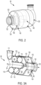
FIG. 2 is a perspective view of an exterior of a water extractor of the ECS ofFIG. 1 in accordance with embodiments; -
FIG. 3A is a cutaway perspective view of an interior of the water extractor of the ECS ofFIG. 1 in accordance with embodiments; -
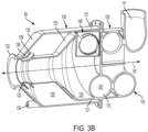
FIG. 3B is a cutaway perspective view of an interior of the water extractor of the ECS ofFIG. 1 in accordance with embodiments -
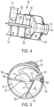
FIG. 4 is a cutaway perspective view of an interior of the water extractor of the ECS ofFIG. 1 in accordance with alternative embodiments; -
FIG. 5 is a perspective view of a scupper and secondary scuppers of a water extractor in accordance with embodiments; -
FIG. 6 is a cutaway perspective view of a semi-annular scupper in accordance with embodiments; -
FIG. 7 is an enlarged perspective view of a chamfered lip of the semi-annular scupper ofFIG. 6 in accordance with embodiments; -
FIG. 8 is a side view of a water extractor and an insert provided as an annular scupper in accordance with embodiments; and -
FIG. 9 is a perspective view of the insert ofFIG. 8 in accordance with embodiments. - These and other advantages and features will become more apparent from the following description taken in conjunction with the drawings.
- As will be described below, an MPWC with a helical flow channel and radial scuppers is provided with helical revolutions for the helical flow channel. The MPWC centrifuges water droplets and/or fog coming out of an ACM turbine and directs coalesced free moisture into radial scuppers that are connected to a downstream settling chamber where the free moisture is collected and removed from the system.
- With reference to
FIG. 1 , a schematic diagram of an example of aportion 22, also referred to as a "pack," of anECS 20 is shown. It is to be understood that, although theECS 20 is described with reference to an aircraft, alternative applications are also within the scope of this disclosure. - Each
pack 22 includes aRAM air circuit 30 including a shell orduct 32 within which one or more heat exchangers are located. Theshell 32 can receive and direct a medium A1, such as ram air for example, through a portion of theECS 20. The one or more heat exchangers are devices built for efficient heat transfer from one medium to another. Examples of the type of heat exchangers that may be used, include, but are not limited to, double pipe, shell and tube, plate, plate and shell, adiabatic shell, plate fin, pillow plate and fluid heat exchangers. - The one or more heat exchangers arranged within the
shell 32 may be referred to as ram heat exchangers and can include aprimary heat exchanger 34 and asecondary heat exchanger 36. Within theprimary heat exchanger 34 and thesecondary heat exchanger 36, ram air, such as outside air for example, acts as a heat sink to cool one or more mediums. - The
pack 22 additionally includes at least one compressing device 40. Each compressing device 40 includes acompressor 42, a turbine 44 and afan 46, all of which are operably coupled to one another via ashaft 48. Thefan 46, thecompressor 42 and the turbine 44 cooperatively define an air cycle machine (ACM). Thecompressor 42 is a mechanical device that raises a pressure of a medium and can be driven by another mechanical device (e.g., a motor or a medium via a turbine). Examples of compressor types include centrifugal, diagonal or mixed-flow, axial-flow, reciprocating, ionic liquid piston, rotary screw, rotary vane, scroll, diaphragm, air bubble, etc. - The turbine 44 is a mechanical device that expands and extracts work from a medium (also referred to as extracting energy). In the compressing device 40, the turbine 44 drives the
compressor 42 and thefan 46 via theshaft 48. Thefan 46 is a mechanical device that can force via push or pull methods the medium A1 (e.g., ram air) through theshell 32 and across theprimary heat exchanger 34 and thesecondary heat exchanger 36 at a variable rate to control temperatures. - In operation, the
pack 22 is supplied with a medium A2, such as air bled from a gas turbine engine of the aircraft for example. It should be understood that theECS 20 may include any number ofpacks 22 configured to supply conditioned air to various heat loads of the aircraft. The medium A2 is input to theprimary heat exchanger 34 such that the medium A2 is in a heat exchange relationship with another medium A1, such as ram or ambient air for example. After the bleed air A2 is cooled in theprimary heat exchanger 34, the resulting cooler air is communicated through apassage 50 to thecompressor 42 of the compressing device 40. Within the compressor, the medium A2 is compressed to a high pressure. - Compressed medium A2 exits the
compressor 42 through apassage 52 and is provided to thesecondary heat exchanger 36 where the second medium A2 is further cooled by heat exchange with the first medium A1. Compressed, cooled air having water vapor entrained therein exits from thesecondary heat exchanger 36 and flows through aduct 56 to a condensing heat exchanger 58. The condensing heat exchanger 58 is configured to further cool the second medium A2 and water is separated from the cooled second medium A2 via awater extractor 60. Dehumidified air exits thewater extractor 60 and is provided, through apassage 62, to the turbine 44. The bleed air A2 is expanded and water vapor in the air is further condensed through the turbine 44 of the ACM 40. The cooled second medium A2 flows through a passage 64 back to the condensing heat exchanger 58, where the air is heated to a relatively warmed temperature, and is then supplied to the one or more air loads (illustrated schematically at 66) of the aircraft, such as to the cabin for example. - It should be understood that the
pack 22 illustrated and described herein is intended as an example only, and that anyECS 20 including awater extractor 60 is within the scope of the disclosure. In an embodiment, theECS 20 may be configured such that thewater extractor 60 is arranged directly downstream from an outlet of the turbine 44. In such embodiments, the water contained within the airflow provided to thewater extractor 60 is a fine mist or fog. - With reference to
FIGS. 2-5 , thewater extractor 60 ofFIG. 1 will now be described in greater detail. - As shown in
FIGS. 2, 3A and3B in particular, thewater extractor 60 includes ahelical channel 110, atoroidal body 120, anouter body 130 and ascupper 140. - The
helical channel 110 includes aninlet 111, anoutlet 112 and ahelical section 113 fluidly interposed between theinlet 111 and theoutlet 112. A medium, such as an airstream enters thehelical channel 110 via theinlet 111 and passes through thehelical section 113 before exiting thehelical channel 110 via theoutlet 112. Within thehelical section 113, the moisture, such as water, is removed from the medium by centrifugal forces and generally flows along a radially outer side of thehelical section 113 whereas the air flows through the middle and along a radially interior side of thehelical section 113. - The
toroidal body 120 is elongate along longitudinal axis B1 and includestoroidal section 121, afirst outlet 122 and atapered section 123 axially interposed between thetoroidal section 121 and thefirst outlet 122. Thetoroidal section 121 encompasses at least thehelical section 113 and theoutlet 112 of thehelical channel 110. Thetoroidal section 121 and the taperedsection 123 cooperatively define anexhaust plenum 125 beyond theoutlet 112 such that, as the medium exits thehelical channel 110 via theoutlet 112, the medium enters into theexhaust plenum 125. The taperedsection 123 is tapered inwardly with decreasing distance toward thefirst outlet 122 along the longitudinal axis B1 to urge the medium to flow from theexhaust plenum 125 and toward and through thefirst outlet 122. - In accordance with embodiments, the
helical section 113 of thehelical channel 110 can include one, two or more helix revolutions in thetoroidal section 121 of thetoroidal body 120. These one, two or more helix revolutions provide thehelical section 113 with sufficient helical or circumferential length to allow for a desired amount of moisture separation from the medium. - In accordance with further embodiments and as shown in
FIGS. 3A ,3B and4 , thehelical section 113 of thehelical channel 110 has one of an annular or circular cross-section 301 (seeFIGS. 3A and3B ), a polygonal or rectangular cross-section 401 (seeFIG. 4 ) and a cross-section of varying shape, such as a case in which thehelical section 113 has a circular cross section that becomes increasingly annular with decreasing distance toward thefirst outlet 122 along thelongitudinal axis B 1. - The
outer body 130 includes acylindrical section 131, asecond outlet 132, atapered section 133 axially interposed between thecylindrical section 131 and thesecond outlet 132 and adrain 134. Thecylindrical section 131 is disposed about the taperedsection 123 and about respective proximal portions of thetoroidal section 121 and thefirst outlet 122. Thesecond outlet 132 is disposed adjacent to and about thefirst outlet 122 along the longitudinal axis B1 to form a narrow channel about thefirst outlet 122. The taperedsection 133 is tapered inwardly with decreasing distance toward thesecond outlet 132 along the longitudinal axis B1. Thecylindrical section 131 and the taperedsection 133 cooperatively define a settlingchamber 135 about the taperedsection 123 and about respective proximal portions of thetoroidal section 121 and thefirst outlet 122. Thedrain 134 is disposed and configured to allow for moisture that collects in the settlingchamber 135 to drain out of the settlingchamber 135. - At least the
outer body 130 can also include afin arrangement 136 to prevent moisture egress through the second outlet 132 (i.e., through the narrow channel defined about the first outlet 122). Thefin arrangement 136 can be provided as a fin that extends from thesecond outlet 132 and toward thecylindrical section 131 while tapering away from a proximal portion of the taperedsection 133. Moisture that collects in thesetting chamber 135 that migrates along the taperedsection 133 toward thesecond outlet 132 is prevented from exiting through thesecond outlet 132 by thefin arrangement 136. In some cases, the fin arrangement 136' can also be provided on thefirst outlet 122 of thetoroidal body 120 as shown inFIG. 3B . In these or other cases, the fin arrangement 136' can be provided as a fin that extends from thefirst outlet 122 and toward thetoroidal section 121 while tapering away from a proximal portion of thefirst outlet 122. Moisture that collects in thesetting chamber 135 that migrates along the taperedsection 123 and/or the tubular member leading to thefirst outlet 122 toward thefirst outlet 122 is prevented from exiting through thesecond outlet 132 by the fin arrangement 136'. - The
scupper 140 is disposed to direct moisture, which is separated from the medium flowing through thehelical channel 110, from thehelical channel 110 and into the settlingchamber 135. As such, with the medium being flowable from thehelical channel 110 into theexhaust plenum 125 and then sequentially through thefirst outlet 122 and thesecond outlet 132, the medium effectively urges (i.e., pressurizes or entrains) a flow of the collected moisture from the settlingchamber 135 and through thedrain 134. - In accordance with further embodiments and as shown in
FIGS. 3A ,3B ,4 and 5 , thewater extractor 60 can further includesecondary scuppers 150. Thesecondary scuppers 150 can be provided as one, two or more than twosecondary scuppers 150 that are disposed and configured to direct moisture, which is separated from the medium flowing through thehelical channel 110 and theoutlet 112 into theexhaust plenum 125, from theexhaust plenum 125 to the settlingchamber 135. Thesecondary scuppers 150 can be canted at an angle α (seeFIG. 4 ) and can be provided along thetoroidal section 121 within theexhaust plenum 125 to direct moisture that is not captured by thescupper 140 into the settlingchamber 135. Eachsecondary scupper 150 includes alip 151 disposed along an elongate opening in thetoroidal section 121. - While numbers of the
secondary scuppers 150 can vary, it is to be understood that the number may be limited (e.g., to two secondary scuppers 150) to avoid diverting an excess of the medium from theexhaust plenum 125 to the settlingchamber 135. - In addition, although the
scupper 140 and thesecondary scuppers 150 can be placed at various circumferential positions about the longitudinal axis B1, thescupper 140 can in some cases be placed at about the 3:00 position as shown inFIG. 4 with thesecondary scuppers 150 at about 6:00 and 9:00. In these positions, moisture separation effects provided by thescupper 140 and thesecondary scuppers 150 can be maximized. For example, with thescupper 140 placed at the 3:00 position, thescupper 140 is disposed to direct downwardly flowing moisture from the radially outer wall of thehelical section 113 of thehelical channel 110 and into the settlingchamber 135. - It is to be understood that in cases in which the
water extractor 60 is deployed in an aircraft or another vehicle, an attitude of the aircraft can alter an attitude of thescupper 140 and thesecondary cuppers 150 in a manner that could momentarily limit their effectiveness in moisture separation. It is to be further understood, however, that these are transient conditions and that, during normal operations of the aircraft/vehicle, thescupper 140 and thesecondary scuppers 150 will be positioned at their respective 3:00, 6:00 and 9:00 positions. - With continued reference to
FIG. 5 and with additional reference toFIGS. 6 and 7 , thescupper 140 includes a scuppergap forming body 141 that is disposable along at least an outer wall of thehelical section 113 of thehelical channel 110. The scuppergap forming body 141 can be provided with an annular scupper element (seeFIG. 5 ) or a semi-annular scupper element (seeFIG. 6 ). In either case, the scuppergap forming body 141 can include a chamfered scupper lip 142 (seeFIG. 7 ), which is angled to encourage moisture flow out of thehelical section 113 of thehelical channel 110. - The
scupper 140 can be generally provided as an insert (seeFIG. 5 ) that is insertable into thetoroidal body 120. - With reference to
FIGS. 8 and 9 , thewater extractor 60 can include thehelical channel 110, thetoroidal body 120, theouter body 130 generally as described above with reference toFIGS. 2-5 as well as aninsert 801. Theinsert 801 is insertable into thetoroidal body 120 throughslot 802 and, as described above, is provided as an annular scupper 803 (seeFIG. 9 ) or as a semi-annular scupper (seeFIG. 6 ) that is disposed to direct moisture, which is separated from a medium flowing through thehelical channel 110, from thehelical channel 110 and into the settlingchamber 135. - As shown in
FIG. 9 , theannular scupper 803 includes aflange 910 by which theannular scupper 803 is securable to thetoroidal body 120. Theflange 910 is formed to define anopening 911, which is communicative with the settling chamber 135 (seeFIGS. 3A ,3B and4 ). Theannular scupper 803 further includes aleading side 920, which faces toward incoming medium flow in thehelical section 113 of thehelical channel 110, a trailingside 930, which faces away from the incoming medium flow in thehelical section 113, and anannular body 940. Both the leadingside 920 and the trailingside 930 are supported on theflange 910 and taper together with increasing distance from theflange 910. The leadingside 920 is formed to define aleading side aperture 921 and the trailingside 930 is formed to define a trailingside aperture 931. Theannular body 940 is supported in the trailingside aperture 931 by edges of the trailingside 930 at the trailingside aperture 931 and extends axially forwardly beyond the leadingside 920. In this way, theannular body 940 form agap 941 with the edges of the leadingside 920 in the leadingside aperture 921. Thegap 941 can be recessed from a leading edge 942 of theannular body 940 and is fluidly communicative with theopening 911 formed by theflange 910. - As moisture separated from the medium flowing through the
helical channel 110 moves along the wall of thehelical section 113 of thehelical channel 110, the moisture passes the leading edge 942 of theannular body 940 and enters theannular scupper 803 through thegap 941. The moisture continues moving through theannular scupper 803 and exits via theopening 911 of theflange 910 into the settlingchamber 135. - It is to be understood that, where the
insert 801 is provided as the semi-annular scupper (seeFIG. 6 ), the semi-annular scupper has a similar construction as theannular scupper 803 ofFIGS. 8 and 9 except that, where thegap 941 of theannular scupper 803 is a continuous annulus, the corresponding gap 941' in the semi-annular scupper is a continuous semi-annulus. - Technical effects and benefits of the present disclosure are the provision of a MPWC with the helical flow channel and the radial scuppers that provides for a compact method to centrifuge and coalesce water droplets and/or fog for collection and removal from an ECS. The MPWC with the helical flow channel and the radial scuppers can also minimizing or eliminating a need for a condenser in an ECS. In addition, chamfered radial scuppers can be provided in-line with centrifugal flow to maximize free water capture and a circumferential drain channel can enable optimized placement or connection of radial scuppers to a settling chamber.
- The scope of protection is defined by the appended claims.
Claims (15)
- A water extractor, comprising:a helical channel (110);a toroidal body (120) encompassing the helical channel and defining an exhaust plenum (125) beyond the helical channel and comprising a first outlet (122);an outer body (130) defining a settling chamber (135) about the toroidal body and comprising a second outlet (132) and a drain (134); anda scupper (140) disposed to direct moisture, which is separated from a medium flowing through the helical channel, from the helical channel and into the settling chamber,the medium being flowable from the helical channel into the exhaust plenum and then sequentially through the first and second outlets to pressurize collected moisture flow from the settling chamber and through the drain.
- The water extractor according to claim 1, wherein the helical channel (110) comprises one, two or more revolutions in the toroidal body (120); and/or wherein the helical channel (110) has one of an annular cross-section, a polygonal cross-section and a cross-section of varying shape.
- The water extractor according to claim 1 or 2, wherein the scupper (140) comprises a scupper gap forming body (141) along an outer wall of the helical channel (110); and optionally wherein the scupper gap forming body comprises a chamfered scupper lip (142).
- The water extractor according to any preceding claim, wherein the scupper (140) is an insert that is insertable into the toroidal body (120).
- The water extractor according to any preceding claim, wherein the scupper (140) is disposed to direct downwardly flowing moisture from the helical channel (110) and into the settling chamber (135); and/or further comprising canted secondary scuppers (150) disposed to direct moisture, which is separated from the medium, from the exhaust plenum (125) to the settling chamber (135).
- The water extractor according to any preceding claim, further comprising a fin arrangement (136) to prevent moisture egress through the second outlet (132).
- A water extractor, comprising:a helical channel (110);a toroidal body (120) encompassing the helical channel and defining an exhaust plenum (125) beyond the helical channel and comprising a first outlet (122);an outer body (130) defining a settling chamber (135) about the toroidal body (120) and comprising a second outlet (132) and a drain (134); andan insert (801), which is insertable into the toroidal body, and which comprises an annular scupper (803) disposed to direct moisture, which is separated from a medium flowing through the helical channel, from the helical channel and into the settling chamber,the medium being flowable from the helical channel into the exhaust plenum and then sequentially through the first and second outlets to pressurize collected moisture flow from the settling chamber and through the drain.
- The water extractor according to claim 7, wherein the helical channel (110) comprises one, two or more revolutions in the toroidal body (120).
- The water extractor according to claim 7 or 8, wherein the helical channel (110) has one of an annular cross-section, a polygonal cross-section and a cross-section of varying shape.
- The water extractor according to claim 7, 8 or 9, wherein the annular scupper (803) is angled normally with respect to the helical channel (110); and/or wherein the annular scupper (803) is disposed to direct downwardly flowing moisture from the helical channel (110) and into the settling chamber (135).
- The water extractor according to any of claims 7 to 10, wherein the annular scupper (803) comprises:a flange (910) defining an opening (911) communicative with the settling chamber (135);leading and trailing sides (920, 930) supported on the flange, the leading side (920) defining a leading side aperture (921) and the trailing side (930) defining a trailing side aperture (931); andan annular body (940), which is supported in the trailing side aperture by the trailing side and which extends beyond the leading side to form a gap (941) with the leading side in the leading side aperture, the gap being communicative with the opening.
- The water extractor according to any of claims 7 to 11, further comprising canted secondary scuppers (150) disposed to direct moisture, which is separated from the medium, from the exhaust plenum to the settling chamber (135); and/or further comprising a fin arrangement (136) to prevent moisture egress through the second outlet (132).
- An annular scupper (803), comprising:a flange (910) defining an opening (911);a leading side (920) supported on the flange and defining a leading side aperture (921);a trailing side (930) supported on the flange and defining a trailing side aperture (931); andan annular body (940), which is supported in the trailing side aperture by the trailing side and which extends beyond the leading side to form a gap (941) with the leading side in the leading side aperture, the gap being communicative with the opening.
- The annular scupper according to claim 13, wherein the gap (941) is recessed from a leading edge (920) of the annular body (940).
- The annular scupper according to claim 13 or 14, wherein the leading and trailing sides (920, 930) taper together with increasing distance from the flange (910).
Applications Claiming Priority (1)
| Application Number | Priority Date | Filing Date | Title |
|---|---|---|---|
| US17/733,477 US12036498B2 (en) | 2022-04-29 | 2022-04-29 | Mid-pressure water collector (MPWC) with helical flow channel and radial scuppers |
Publications (4)
| Publication Number | Publication Date |
|---|---|
| EP4268928A2 true EP4268928A2 (en) | 2023-11-01 |
| EP4268928A3 EP4268928A3 (en) | 2023-11-08 |
| EP4268928B1 EP4268928B1 (en) | 2025-11-05 |
| EP4268928B8 EP4268928B8 (en) | 2025-12-10 |
Family
ID=86185373
Family Applications (1)
| Application Number | Title | Priority Date | Filing Date |
|---|---|---|---|
| EP23169556.0A Active EP4268928B8 (en) | 2022-04-29 | 2023-04-24 | Mid-pressure water collector (mpwc) with helical flow channel and radial scuppers |
Country Status (2)
| Country | Link |
|---|---|
| US (2) | US12036498B2 (en) |
| EP (1) | EP4268928B8 (en) |
Family Cites Families (37)
| Publication number | Priority date | Publication date | Assignee | Title |
|---|---|---|---|---|
| US1306003A (en) * | 1919-06-10 | Separator | ||
| US948062A (en) * | 1907-08-17 | 1910-02-01 | Cambria Steel Company | Gas-cleaning apparatus. |
| US1387748A (en) * | 1921-02-24 | 1921-08-16 | Anti Corrosion Engineering Com | Apparatus for removing gases from water |
| US1799684A (en) * | 1929-03-27 | 1931-04-07 | Gilbert Harry | Air compressor |
| US1958577A (en) * | 1930-06-12 | 1934-05-15 | Glarence F Hirshfeld | Apparatus for dust separation |
| US2015076A (en) * | 1933-04-25 | 1935-09-24 | Lavigne Jean Loumiet Et | Centrifugal separator |
| US2193460A (en) * | 1936-03-10 | 1940-03-12 | Lavigne Jean Loumiet Et | Separator |
| US2705053A (en) * | 1953-05-14 | 1955-03-29 | Doak Aircraft Co Inc | Oil degasification |
| US2889044A (en) * | 1955-05-23 | 1959-06-02 | Paul O Tobeler | Device to separate minerals by specific weight |
| US3603569A (en) * | 1969-12-29 | 1971-09-07 | Kaiser Aluminum & Chemical | Kiln preheat and drying section |
| US3706383A (en) * | 1970-05-21 | 1972-12-19 | James R Palma | Fluid separator |
| US3951813A (en) * | 1973-07-02 | 1976-04-20 | Palma James R | Fluid separator or mixer |
| US3875061A (en) * | 1973-08-27 | 1975-04-01 | James R Palma | Centrifugal separator with field effect separation |
| US4179273A (en) * | 1978-10-27 | 1979-12-18 | Grumman Aerospace Corporation | Dual scavenging separator |
| US4681610A (en) * | 1986-02-13 | 1987-07-21 | United Technologies Corporation | High performance water collector |
| AUPP624298A0 (en) * | 1998-09-30 | 1998-10-22 | Alcos Technologies Pty Ltd | Cyclonic evaporator |
| US6981995B2 (en) * | 2001-05-25 | 2006-01-03 | Lombana Jorge L | Separator for fluids and solids |
| DE60333599D1 (en) * | 2003-05-16 | 2010-09-09 | Haimo Technologies Inc | ADJUSTABLE GAS LIQUID CENTRIFUGAL SEPARATOR AND SEPARATION METHOD |
| DE102004036568A1 (en) * | 2004-07-28 | 2006-02-16 | Liebherr-Aerospace Lindenberg Gmbh | Water separator for air conditioners |
| US7279022B2 (en) * | 2005-01-24 | 2007-10-09 | Industrial Widget Works Company | Spiraltrap: devices and methods for the trapping particulate matter in exhaust and of other pollutants |
| US7708146B2 (en) * | 2007-11-14 | 2010-05-04 | Jan Kruyer | Hydrocyclone and associated methods |
| US8875535B2 (en) * | 2009-12-02 | 2014-11-04 | Hamilton Sundstrand Corporation | Compact condenser module including a tortuous path for removing water droplets from air |
| SG11201408506VA (en) * | 2012-07-06 | 2015-03-30 | Practical Analyzer Solutions Pte Ltd | Centrifugal cyclone separator |
| US9610525B2 (en) * | 2015-03-27 | 2017-04-04 | The Boeing Company | Centrifugal air separators |
| KR101824115B1 (en) | 2016-02-26 | 2018-02-01 | 삼성중공업 주식회사 | Scupper with stopper for living quarter |
| GB2549461A (en) | 2016-04-12 | 2017-10-25 | Omnidex Ltd | Moisture extraction assembly |
| DE102016109380B3 (en) | 2016-05-20 | 2017-09-21 | Esta Apparatebau Gmbh & Co. Kg | Suction unit with a housing enclosing a process space |
| US10265651B2 (en) | 2016-11-14 | 2019-04-23 | Hamilton Sundstrand Corporation | Compact water extractor |
| US10322621B2 (en) * | 2017-02-15 | 2019-06-18 | Hamilton Sundstrand Corporation | Inertial particle separator for air cycle machine |
| US10526090B2 (en) * | 2017-06-08 | 2020-01-07 | Hamilton Sundstrand Corporation | Tangential entry water separator for aircraft ECS |
| US10744437B2 (en) * | 2017-07-10 | 2020-08-18 | Hamilton Sunstrand Corporation | Vented dynamic pressure recovery module for aircraft ECS |
| US10633099B2 (en) * | 2018-03-12 | 2020-04-28 | Hamilton Sundstrand Corporation | Non-horizontal water extractor |
| US11090592B2 (en) * | 2018-06-22 | 2021-08-17 | Hamilton Sundstrand Corporation | High pressure water collector with radial diffuser |
| US10765982B2 (en) | 2018-06-26 | 2020-09-08 | Hamilton Sundstrand Corporation | Helical water collector |
| US11154804B2 (en) | 2018-12-07 | 2021-10-26 | Hamilton Sundstrand Corporation | Water extractors and methods of making water extractors |
| WO2021224650A1 (en) * | 2020-05-06 | 2021-11-11 | Kulakovskij Kirill | Method and device for separating particles from a fluid |
| US12065251B2 (en) * | 2021-06-29 | 2024-08-20 | Hamilton Sundstrand Corporation | Centrifugal water collector with conical water scupper |
-
2022
- 2022-04-29 US US17/733,477 patent/US12036498B2/en active Active
-
2023
- 2023-04-24 EP EP23169556.0A patent/EP4268928B8/en active Active
-
2024
- 2024-07-12 US US18/771,467 patent/US20240359123A1/en active Pending
Also Published As
| Publication number | Publication date |
|---|---|
| EP4268928B8 (en) | 2025-12-10 |
| EP4268928B1 (en) | 2025-11-05 |
| EP4268928A3 (en) | 2023-11-08 |
| US20230347270A1 (en) | 2023-11-02 |
| US12036498B2 (en) | 2024-07-16 |
| US20240359123A1 (en) | 2024-10-31 |
Similar Documents
| Publication | Publication Date | Title |
|---|---|---|
| EP3489142B1 (en) | Aircraft environmental control system with series bleed air turbines | |
| EP3945023B1 (en) | Aircraft environmental control system | |
| EP3514065B1 (en) | Aircraft environmental control system | |
| EP3412354B1 (en) | Tangential entry water separator for aircraft ecs | |
| EP3480113A1 (en) | Regenerative system ecoecs | |
| EP3354573A1 (en) | Environmental control system in an integrated pack arrangement with one bleed/outflow heat exchanger | |
| EP3427812B1 (en) | Water extractor for environmental control system of an aircraft | |
| EP4467454A2 (en) | All electric ecs with cabin outflow cooled motor drives | |
| EP3944888B1 (en) | High-pressure annular water collector with axial swirl vanes for an air cycle environmental control system | |
| CN108357681B (en) | Advanced environmental control system in integrated sub-packaging arrangement with two bleed/outflow heat exchangers | |
| EP3945029B1 (en) | Aircraft environmental control system | |
| US20240359800A1 (en) | Centrifugal water collector with conical water scupper | |
| EP4316988B1 (en) | Mid-pressure water separation for environmental control system | |
| EP3677508A1 (en) | Concentric turbine condensing cycle | |
| EP4001117A2 (en) | Environmental control system for supersonic commercial aircraft | |
| US20170045243A1 (en) | Water extractor device using scuppers | |
| EP4268928B1 (en) | Mid-pressure water collector (mpwc) with helical flow channel and radial scuppers | |
| EP4331991A1 (en) | Environmental control system with low inlet pressure | |
| EP4282761B1 (en) | Vapor compression system for aerospace applications | |
| EP4506254A1 (en) | Drain system for ecs water collection | |
| EP4269245A1 (en) | Environmental control system and vapor control system water separation overlap |
Legal Events
| Date | Code | Title | Description |
|---|---|---|---|
| PUAI | Public reference made under article 153(3) epc to a published international application that has entered the european phase |
Free format text: ORIGINAL CODE: 0009012 |
|
| STAA | Information on the status of an ep patent application or granted ep patent |
Free format text: STATUS: THE APPLICATION HAS BEEN PUBLISHED |
|
| PUAL | Search report despatched |
Free format text: ORIGINAL CODE: 0009013 |
|
| AK | Designated contracting states |
Kind code of ref document: A2 Designated state(s): AL AT BE BG CH CY CZ DE DK EE ES FI FR GB GR HR HU IE IS IT LI LT LU LV MC ME MK MT NL NO PL PT RO RS SE SI SK SM TR |
|
| AK | Designated contracting states |
Kind code of ref document: A3 Designated state(s): AL AT BE BG CH CY CZ DE DK EE ES FI FR GB GR HR HU IE IS IT LI LT LU LV MC ME MK MT NL NO PL PT RO RS SE SI SK SM TR |
|
| RIC1 | Information provided on ipc code assigned before grant |
Ipc: B01D 45/16 20060101AFI20231002BHEP |
|
| STAA | Information on the status of an ep patent application or granted ep patent |
Free format text: STATUS: REQUEST FOR EXAMINATION WAS MADE |
|
| 17P | Request for examination filed |
Effective date: 20240507 |
|
| RBV | Designated contracting states (corrected) |
Designated state(s): AL AT BE BG CH CY CZ DE DK EE ES FI FR GB GR HR HU IE IS IT LI LT LU LV MC ME MK MT NL NO PL PT RO RS SE SI SK SM TR |
|
| GRAP | Despatch of communication of intention to grant a patent |
Free format text: ORIGINAL CODE: EPIDOSNIGR1 |
|
| STAA | Information on the status of an ep patent application or granted ep patent |
Free format text: STATUS: GRANT OF PATENT IS INTENDED |
|
| INTG | Intention to grant announced |
Effective date: 20250602 |
|
| GRAS | Grant fee paid |
Free format text: ORIGINAL CODE: EPIDOSNIGR3 |
|
| GRAA | (expected) grant |
Free format text: ORIGINAL CODE: 0009210 |
|
| STAA | Information on the status of an ep patent application or granted ep patent |
Free format text: STATUS: THE PATENT HAS BEEN GRANTED |
|
| AK | Designated contracting states |
Kind code of ref document: B1 Designated state(s): AL AT BE BG CH CY CZ DE DK EE ES FI FR GB GR HR HU IE IS IT LI LT LU LV MC ME MK MT NL NO PL PT RO RS SE SI SK SM TR |
|
| REG | Reference to a national code |
Ref country code: CH Ref legal event code: F10 Free format text: ST27 STATUS EVENT CODE: U-0-0-F10-F00 (AS PROVIDED BY THE NATIONAL OFFICE) Effective date: 20251105 Ref country code: GB Ref legal event code: FG4D |
|
| REG | Reference to a national code |
Ref country code: CH Ref legal event code: Q17 Free format text: ST27 STATUS EVENT CODE: U-0-0-Q10-Q17 (AS PROVIDED BY THE NATIONAL OFFICE) Effective date: 20251112 |
|
| REG | Reference to a national code |
Ref country code: DE Ref legal event code: R096 Ref document number: 602023008186 Country of ref document: DE |
|
| REG | Reference to a national code |
Ref country code: IE Ref legal event code: FG4D |
|
| REG | Reference to a national code |
Ref country code: NL Ref legal event code: MP Effective date: 20251105 |
|
| PG25 | Lapsed in a contracting state [announced via postgrant information from national office to epo] |
Ref country code: ES Free format text: LAPSE BECAUSE OF FAILURE TO SUBMIT A TRANSLATION OF THE DESCRIPTION OR TO PAY THE FEE WITHIN THE PRESCRIBED TIME-LIMIT Effective date: 20251105 |
|
| REG | Reference to a national code |
Ref country code: LT Ref legal event code: MG9D |
|
| PG25 | Lapsed in a contracting state [announced via postgrant information from national office to epo] |
Ref country code: NO Free format text: LAPSE BECAUSE OF FAILURE TO SUBMIT A TRANSLATION OF THE DESCRIPTION OR TO PAY THE FEE WITHIN THE PRESCRIBED TIME-LIMIT Effective date: 20260205 |
|
| PG25 | Lapsed in a contracting state [announced via postgrant information from national office to epo] |
Ref country code: FI Free format text: LAPSE BECAUSE OF FAILURE TO SUBMIT A TRANSLATION OF THE DESCRIPTION OR TO PAY THE FEE WITHIN THE PRESCRIBED TIME-LIMIT Effective date: 20251105 Ref country code: HR Free format text: LAPSE BECAUSE OF FAILURE TO SUBMIT A TRANSLATION OF THE DESCRIPTION OR TO PAY THE FEE WITHIN THE PRESCRIBED TIME-LIMIT Effective date: 20251105 Ref country code: AT Free format text: LAPSE BECAUSE OF FAILURE TO SUBMIT A TRANSLATION OF THE DESCRIPTION OR TO PAY THE FEE WITHIN THE PRESCRIBED TIME-LIMIT Effective date: 20251105 |
|
| REG | Reference to a national code |
Ref country code: AT Ref legal event code: MK05 Ref document number: 1853764 Country of ref document: AT Kind code of ref document: T Effective date: 20251105 |
|
| PG25 | Lapsed in a contracting state [announced via postgrant information from national office to epo] |
Ref country code: NL Free format text: LAPSE BECAUSE OF FAILURE TO SUBMIT A TRANSLATION OF THE DESCRIPTION OR TO PAY THE FEE WITHIN THE PRESCRIBED TIME-LIMIT Effective date: 20251105 |
|
| PG25 | Lapsed in a contracting state [announced via postgrant information from national office to epo] |
Ref country code: RS Free format text: LAPSE BECAUSE OF FAILURE TO SUBMIT A TRANSLATION OF THE DESCRIPTION OR TO PAY THE FEE WITHIN THE PRESCRIBED TIME-LIMIT Effective date: 20260205 |
|
| PG25 | Lapsed in a contracting state [announced via postgrant information from national office to epo] |
Ref country code: IS Free format text: LAPSE BECAUSE OF FAILURE TO SUBMIT A TRANSLATION OF THE DESCRIPTION OR TO PAY THE FEE WITHIN THE PRESCRIBED TIME-LIMIT Effective date: 20260305 |
|
| PGFP | Annual fee paid to national office [announced via postgrant information from national office to epo] |
Ref country code: FR Payment date: 20260320 Year of fee payment: 4 |
|
| PG25 | Lapsed in a contracting state [announced via postgrant information from national office to epo] |
Ref country code: PT Free format text: LAPSE BECAUSE OF FAILURE TO SUBMIT A TRANSLATION OF THE DESCRIPTION OR TO PAY THE FEE WITHIN THE PRESCRIBED TIME-LIMIT Effective date: 20260305 |
|
| PG25 | Lapsed in a contracting state [announced via postgrant information from national office to epo] |
Ref country code: PL Free format text: LAPSE BECAUSE OF FAILURE TO SUBMIT A TRANSLATION OF THE DESCRIPTION OR TO PAY THE FEE WITHIN THE PRESCRIBED TIME-LIMIT Effective date: 20251105 |
|
| PG25 | Lapsed in a contracting state [announced via postgrant information from national office to epo] |
Ref country code: LV Free format text: LAPSE BECAUSE OF FAILURE TO SUBMIT A TRANSLATION OF THE DESCRIPTION OR TO PAY THE FEE WITHIN THE PRESCRIBED TIME-LIMIT Effective date: 20251105 |
|
| PG25 | Lapsed in a contracting state [announced via postgrant information from national office to epo] |
Ref country code: BG Free format text: LAPSE BECAUSE OF FAILURE TO SUBMIT A TRANSLATION OF THE DESCRIPTION OR TO PAY THE FEE WITHIN THE PRESCRIBED TIME-LIMIT Effective date: 20251105 |