EP4268745A1 - Plasma ablasion system and plasma guide wire - Google Patents
Plasma ablasion system and plasma guide wire Download PDFInfo
- Publication number
- EP4268745A1 EP4268745A1 EP21910439.5A EP21910439A EP4268745A1 EP 4268745 A1 EP4268745 A1 EP 4268745A1 EP 21910439 A EP21910439 A EP 21910439A EP 4268745 A1 EP4268745 A1 EP 4268745A1
- Authority
- EP
- European Patent Office
- Prior art keywords
- electrode
- guide wire
- plasma
- distal end
- catheter
- Prior art date
- Legal status (The legal status is an assumption and is not a legal conclusion. Google has not performed a legal analysis and makes no representation as to the accuracy of the status listed.)
- Pending
Links
- 238000002679 ablation Methods 0.000 claims abstract description 88
- 230000002787 reinforcement Effects 0.000 claims description 14
- 238000012360 testing method Methods 0.000 description 56
- 238000010586 diagram Methods 0.000 description 30
- 238000000034 method Methods 0.000 description 25
- 210000001519 tissue Anatomy 0.000 description 22
- 230000000694 effects Effects 0.000 description 17
- 238000011156 evaluation Methods 0.000 description 16
- 230000002093 peripheral effect Effects 0.000 description 12
- 210000004204 blood vessel Anatomy 0.000 description 8
- 238000012986 modification Methods 0.000 description 8
- 230000004048 modification Effects 0.000 description 8
- -1 polyethylene Polymers 0.000 description 8
- 238000004804 winding Methods 0.000 description 8
- 239000003550 marker Substances 0.000 description 7
- 239000000463 material Substances 0.000 description 7
- 239000002504 physiological saline solution Substances 0.000 description 6
- 230000003902 lesion Effects 0.000 description 5
- 229920005989 resin Polymers 0.000 description 5
- 239000011347 resin Substances 0.000 description 5
- 239000000523 sample Substances 0.000 description 5
- 229910000831 Steel Inorganic materials 0.000 description 4
- 229910045601 alloy Inorganic materials 0.000 description 4
- 239000000956 alloy Substances 0.000 description 4
- 210000001124 body fluid Anatomy 0.000 description 4
- 239000010839 body fluid Substances 0.000 description 4
- 239000004020 conductor Substances 0.000 description 4
- 238000005520 cutting process Methods 0.000 description 4
- 239000005038 ethylene vinyl acetate Substances 0.000 description 4
- 238000002474 experimental method Methods 0.000 description 4
- 210000004907 gland Anatomy 0.000 description 4
- PCHJSUWPFVWCPO-UHFFFAOYSA-N gold Chemical compound [Au] PCHJSUWPFVWCPO-UHFFFAOYSA-N 0.000 description 4
- 229910052737 gold Inorganic materials 0.000 description 4
- 239000010931 gold Substances 0.000 description 4
- 229910001000 nickel titanium Inorganic materials 0.000 description 4
- BASFCYQUMIYNBI-UHFFFAOYSA-N platinum Chemical compound [Pt] BASFCYQUMIYNBI-UHFFFAOYSA-N 0.000 description 4
- 229920001200 poly(ethylene-vinyl acetate) Polymers 0.000 description 4
- 239000010935 stainless steel Substances 0.000 description 4
- 229910001220 stainless steel Inorganic materials 0.000 description 4
- 239000010959 steel Substances 0.000 description 4
- 239000000126 substance Substances 0.000 description 4
- JOYRKODLDBILNP-UHFFFAOYSA-N Ethyl urethane Chemical compound CCOC(N)=O JOYRKODLDBILNP-UHFFFAOYSA-N 0.000 description 3
- 238000011298 ablation treatment Methods 0.000 description 3
- 230000006793 arrhythmia Effects 0.000 description 3
- 206010003119 arrhythmia Diseases 0.000 description 3
- 229920001577 copolymer Polymers 0.000 description 3
- 230000002500 effect on skin Effects 0.000 description 3
- 229920002635 polyurethane Polymers 0.000 description 3
- 239000004814 polyurethane Substances 0.000 description 3
- 230000007704 transition Effects 0.000 description 3
- 238000003466 welding Methods 0.000 description 3
- 208000031481 Pathologic Constriction Diseases 0.000 description 2
- 239000004952 Polyamide Substances 0.000 description 2
- 239000004698 Polyethylene Substances 0.000 description 2
- 239000004743 Polypropylene Substances 0.000 description 2
- BQCADISMDOOEFD-UHFFFAOYSA-N Silver Chemical compound [Ag] BQCADISMDOOEFD-UHFFFAOYSA-N 0.000 description 2
- 210000003445 biliary tract Anatomy 0.000 description 2
- VNTLIPZTSJSULJ-UHFFFAOYSA-N chromium molybdenum Chemical compound [Cr].[Mo] VNTLIPZTSJSULJ-UHFFFAOYSA-N 0.000 description 2
- OGSYQYXYGXIQFH-UHFFFAOYSA-N chromium molybdenum nickel Chemical compound [Cr].[Ni].[Mo] OGSYQYXYGXIQFH-UHFFFAOYSA-N 0.000 description 2
- 230000001684 chronic effect Effects 0.000 description 2
- 229920001971 elastomer Polymers 0.000 description 2
- 239000000806 elastomer Substances 0.000 description 2
- 230000005611 electricity Effects 0.000 description 2
- 210000004392 genitalia Anatomy 0.000 description 2
- 239000011810 insulating material Substances 0.000 description 2
- 229920000126 latex Polymers 0.000 description 2
- 239000007788 liquid Substances 0.000 description 2
- 210000002751 lymph Anatomy 0.000 description 2
- 238000004519 manufacturing process Methods 0.000 description 2
- 238000000691 measurement method Methods 0.000 description 2
- 210000004798 organs belonging to the digestive system Anatomy 0.000 description 2
- 229920013653 perfluoroalkoxyethylene Polymers 0.000 description 2
- 229910052697 platinum Inorganic materials 0.000 description 2
- 229920002647 polyamide Polymers 0.000 description 2
- 229920000728 polyester Polymers 0.000 description 2
- 229920000573 polyethylene Polymers 0.000 description 2
- 229920000139 polyethylene terephthalate Polymers 0.000 description 2
- 239000005020 polyethylene terephthalate Substances 0.000 description 2
- 229920000098 polyolefin Polymers 0.000 description 2
- 229920006124 polyolefin elastomer Polymers 0.000 description 2
- 229920001155 polypropylene Polymers 0.000 description 2
- 229920003225 polyurethane elastomer Polymers 0.000 description 2
- 229920000915 polyvinyl chloride Polymers 0.000 description 2
- 239000004800 polyvinyl chloride Substances 0.000 description 2
- 210000002345 respiratory system Anatomy 0.000 description 2
- 230000003248 secreting effect Effects 0.000 description 2
- 230000035939 shock Effects 0.000 description 2
- 229920002379 silicone rubber Polymers 0.000 description 2
- 239000004945 silicone rubber Substances 0.000 description 2
- 229910052709 silver Inorganic materials 0.000 description 2
- 239000004332 silver Substances 0.000 description 2
- 230000036262 stenosis Effects 0.000 description 2
- 208000037804 stenosis Diseases 0.000 description 2
- 229920005992 thermoplastic resin Polymers 0.000 description 2
- WFKWXMTUELFFGS-UHFFFAOYSA-N tungsten Chemical compound [W] WFKWXMTUELFFGS-UHFFFAOYSA-N 0.000 description 2
- 229910052721 tungsten Inorganic materials 0.000 description 2
- 239000010937 tungsten Substances 0.000 description 2
- 210000001635 urinary tract Anatomy 0.000 description 2
- 229910015363 Au—Sn Inorganic materials 0.000 description 1
- PYVHTIWHNXTVPF-UHFFFAOYSA-N F.F.F.F.C=C Chemical compound F.F.F.F.C=C PYVHTIWHNXTVPF-UHFFFAOYSA-N 0.000 description 1
- 239000004696 Poly ether ether ketone Substances 0.000 description 1
- 239000004962 Polyamide-imide Substances 0.000 description 1
- 239000004695 Polyether sulfone Substances 0.000 description 1
- 239000004697 Polyetherimide Substances 0.000 description 1
- 239000004642 Polyimide Substances 0.000 description 1
- 229910020836 Sn-Ag Inorganic materials 0.000 description 1
- 229910020988 Sn—Ag Inorganic materials 0.000 description 1
- HCHKCACWOHOZIP-UHFFFAOYSA-N Zinc Chemical compound [Zn] HCHKCACWOHOZIP-UHFFFAOYSA-N 0.000 description 1
- 230000002159 abnormal effect Effects 0.000 description 1
- 230000001154 acute effect Effects 0.000 description 1
- 239000000853 adhesive Substances 0.000 description 1
- 230000001070 adhesive effect Effects 0.000 description 1
- 238000010009 beating Methods 0.000 description 1
- 230000017531 blood circulation Effects 0.000 description 1
- 238000009835 boiling Methods 0.000 description 1
- 239000007767 bonding agent Substances 0.000 description 1
- 238000005219 brazing Methods 0.000 description 1
- 238000004590 computer program Methods 0.000 description 1
- 230000003247 decreasing effect Effects 0.000 description 1
- 238000006073 displacement reaction Methods 0.000 description 1
- 229920006351 engineering plastic Polymers 0.000 description 1
- 229920006332 epoxy adhesive Polymers 0.000 description 1
- 210000003746 feather Anatomy 0.000 description 1
- 238000002594 fluoroscopy Methods 0.000 description 1
- 230000002209 hydrophobic effect Effects 0.000 description 1
- 238000003384 imaging method Methods 0.000 description 1
- 238000002595 magnetic resonance imaging Methods 0.000 description 1
- 238000005259 measurement Methods 0.000 description 1
- 238000002844 melting Methods 0.000 description 1
- 230000008018 melting Effects 0.000 description 1
- 229910052751 metal Inorganic materials 0.000 description 1
- 239000002184 metal Substances 0.000 description 1
- 230000000149 penetrating effect Effects 0.000 description 1
- 229920002492 poly(sulfone) Polymers 0.000 description 1
- 229920002312 polyamide-imide Polymers 0.000 description 1
- 229920006393 polyether sulfone Polymers 0.000 description 1
- 229920002530 polyetherether ketone Polymers 0.000 description 1
- 229920001601 polyetherimide Polymers 0.000 description 1
- 229920001721 polyimide Polymers 0.000 description 1
- 230000003014 reinforcing effect Effects 0.000 description 1
- 230000033764 rhythmic process Effects 0.000 description 1
- 229910000679 solder Inorganic materials 0.000 description 1
- 239000000243 solution Substances 0.000 description 1
- 238000003325 tomography Methods 0.000 description 1
- 238000011282 treatment Methods 0.000 description 1
- 238000012285 ultrasound imaging Methods 0.000 description 1
- 229910052725 zinc Inorganic materials 0.000 description 1
- 239000011701 zinc Substances 0.000 description 1
Images







Classifications
-
- A—HUMAN NECESSITIES
- A61—MEDICAL OR VETERINARY SCIENCE; HYGIENE
- A61B—DIAGNOSIS; SURGERY; IDENTIFICATION
- A61B18/00—Surgical instruments, devices or methods for transferring non-mechanical forms of energy to or from the body
- A61B18/04—Surgical instruments, devices or methods for transferring non-mechanical forms of energy to or from the body by heating
- A61B18/042—Surgical instruments, devices or methods for transferring non-mechanical forms of energy to or from the body by heating using additional gas becoming plasma
-
- A—HUMAN NECESSITIES
- A61—MEDICAL OR VETERINARY SCIENCE; HYGIENE
- A61B—DIAGNOSIS; SURGERY; IDENTIFICATION
- A61B18/00—Surgical instruments, devices or methods for transferring non-mechanical forms of energy to or from the body
- A61B18/04—Surgical instruments, devices or methods for transferring non-mechanical forms of energy to or from the body by heating
- A61B18/12—Surgical instruments, devices or methods for transferring non-mechanical forms of energy to or from the body by heating by passing a current through the tissue to be heated, e.g. high-frequency current
- A61B18/14—Probes or electrodes therefor
- A61B18/1492—Probes or electrodes therefor having a flexible, catheter-like structure, e.g. for heart ablation
-
- A—HUMAN NECESSITIES
- A61—MEDICAL OR VETERINARY SCIENCE; HYGIENE
- A61B—DIAGNOSIS; SURGERY; IDENTIFICATION
- A61B18/00—Surgical instruments, devices or methods for transferring non-mechanical forms of energy to or from the body
- A61B18/04—Surgical instruments, devices or methods for transferring non-mechanical forms of energy to or from the body by heating
- A61B18/12—Surgical instruments, devices or methods for transferring non-mechanical forms of energy to or from the body by heating by passing a current through the tissue to be heated, e.g. high-frequency current
- A61B18/1206—Generators therefor
-
- A—HUMAN NECESSITIES
- A61—MEDICAL OR VETERINARY SCIENCE; HYGIENE
- A61B—DIAGNOSIS; SURGERY; IDENTIFICATION
- A61B18/00—Surgical instruments, devices or methods for transferring non-mechanical forms of energy to or from the body
- A61B2018/00053—Mechanical features of the instrument of device
- A61B2018/00059—Material properties
- A61B2018/00071—Electrical conductivity
- A61B2018/00083—Electrical conductivity low, i.e. electrically insulating
-
- A—HUMAN NECESSITIES
- A61—MEDICAL OR VETERINARY SCIENCE; HYGIENE
- A61B—DIAGNOSIS; SURGERY; IDENTIFICATION
- A61B18/00—Surgical instruments, devices or methods for transferring non-mechanical forms of energy to or from the body
- A61B2018/00571—Surgical instruments, devices or methods for transferring non-mechanical forms of energy to or from the body for achieving a particular surgical effect
- A61B2018/00577—Ablation
-
- A—HUMAN NECESSITIES
- A61—MEDICAL OR VETERINARY SCIENCE; HYGIENE
- A61B—DIAGNOSIS; SURGERY; IDENTIFICATION
- A61B18/00—Surgical instruments, devices or methods for transferring non-mechanical forms of energy to or from the body
- A61B2018/00571—Surgical instruments, devices or methods for transferring non-mechanical forms of energy to or from the body for achieving a particular surgical effect
- A61B2018/00577—Ablation
- A61B2018/00583—Coblation, i.e. ablation using a cold plasma
-
- A—HUMAN NECESSITIES
- A61—MEDICAL OR VETERINARY SCIENCE; HYGIENE
- A61B—DIAGNOSIS; SURGERY; IDENTIFICATION
- A61B18/00—Surgical instruments, devices or methods for transferring non-mechanical forms of energy to or from the body
- A61B18/04—Surgical instruments, devices or methods for transferring non-mechanical forms of energy to or from the body by heating
- A61B18/12—Surgical instruments, devices or methods for transferring non-mechanical forms of energy to or from the body by heating by passing a current through the tissue to be heated, e.g. high-frequency current
- A61B18/14—Probes or electrodes therefor
- A61B2018/1405—Electrodes having a specific shape
- A61B2018/144—Wire
Definitions
- the present invention relates to a plasma ablation system and a plasma guide wire.
- Patent Literatures 1 to 5 disclose devices and systems that can be used in such ablation treatments, in which a living body tissue (a part causing arrhythmia) is excised by using a plasma stream.
- This problem is common to general devices or systems for ablation treatment because the device can not only be inserted in a blood vessel system, but also an organism lumen such as a lymph gland system, a biliary tract system, a urinary tract system, a respiratory tract system, a digestive organ system, a secretory gland, and a genital organ.
- an organism lumen such as a lymph gland system, a biliary tract system, a urinary tract system, a respiratory tract system, a digestive organ system, a secretory gland, and a genital organ.
- the present invention has been made in order to solve at least a part of the above-described problem, and an object of the present invention is to improve safety in the plasma ablation system.
- the present invention has been made in order to solve at least a part of the above-described problem and can be embodied as the following aspects.
- the plasma guide wire since the plasma guide wire has the preshaped distal end portion, an angle between the distal end portion of the plasma guide wire and a living body tissue can be increased compared to a case without preshaping. As a result, a depth of a hole formed on the living body tissue by ablation can be within a desirable range.
- the present invention can be embodied in various manners, such as a plasma guide wire, an RF generator, a plasma ablation system equipped with a plasma guide wire and an RF generator, a method for manufacturing these devices and systems, a method for controlling an RF generator in outputting a high frequency electric power to these devices and systems, and a computer program.
- Fig. 1 is a schematic diagram illustrating an overall configuration of a plasma ablation system 100.
- the plasma ablation system 100 is used for the purpose of opening a chronic total occlusion (CTO), and treating mild to moderate stenosis, significant stenosis, arrhythmia, or the like by ablating a living body tissue.
- the plasma ablation system 100 includes a plasma guide wire 1, a catheter 2, and an RF generator 3.
- the plasma ablation system 100 will be explained below in a case of using the plasma ablation system 100 for the purpose of opening a CTO in a blood vessel as an example, but the plasma ablation system 100 can be used so as to be inserted into not only a blood vessel system, but also an organism lumen such as a lymph gland system, a biliary tract system, a urinary tract system, a respiratory tract system, a digestive organ system, a secretory gland, and a genital organ.
- an organism lumen such as a lymph gland system, a biliary tract system, a urinary tract system, a respiratory tract system, a digestive organ system, a secretory gland, and a genital organ.
- an axis that passes through centers of the plasma guide wire 1 and the catheter 2 in the plasma ablation system 100 is represented by an axis line O (dot and dash line).
- the axis line O coincides with each of the axes that pass through the center of the plasma guide wire 1 excluding a part of the distal end side and the center of the catheter 2.
- the axis line O may be inconsistent with each central axis of the plasma guide wire 1 and the catheter 2.
- Fig. 1 illustrates X-, Y-, and Z-axes orthogonal to each other.
- the X-axis corresponds to a longitudinal direction of the plasma guide wire 1 and the catheter 2
- the Y-axis corresponds to a height direction of the plasma guide wire 1 and the catheter 2
- the Z-axis corresponds to a width direction of the plasma guide wire 1 and the catheter 2.
- the left side (- X-axis direction) in Fig. 1 is referred to as a "distal end side" of the plasma guide wire 1, the catheter 2, and each constitution component
- the right side (+ X-axis direction) in Fig. 1 is referred to as a "proximal end side" of the plasma guide wire 1, the catheter 2, and each constitution component.
- distal end One end of the both ends in the longitudinal direction (X-axis direction) which is positioned on the distal end side is referred to as a "distal end", and the other end positioned on the proximal end side is referred to as a "proximal end”.
- proximal end The distal end and the vicinity thereof are referred to as a “distal end portion”, and the proximal end and the vicinity thereof are referred to as a "proximal end portion”.
- the distal end side is inserted into an inside of a living body, and the proximal end side is operated by an operator such as a surgeon.
- the plasma guide wire 1 has an elongated external shape and includes a conductive first electrode 11 formed on the distal end portion. The detailed configuration of the plasma guide wire 1 is described below. As illustrated in Fig. 1 , the plasma guide wire 1 is used so as to be inserted through a lumen 21L ( Fig. 2 ) of the catheter 2.
- the catheter 2 has an elongated external shape and has a conductive second electrode 23 formed on the distal end side and the lumen 21L through which the plasma guide wire 1 is inserted.
- the catheter 2 according to the first embodiment includes a shaft portion 21, a distal tip 22, the second electrode 23, a proximal end-side electrode 24, and a cable 25.
- the second electrode 23 and the proximal end-side electrode 24 are hatched with shaded lines to distinguish them from other members.
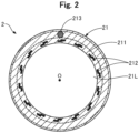
- Fig. 2 is an explanatory diagram illustrating a transverse sectional configuration of the catheter 2 taken along line A-A in Fig. 1 .
- the shaft portion 21 includes a main body portion 211, a reinforcement portion 212, and a connection portion 213.
- the main body portion 211 is a member that constitutes a thick wall portion of the catheter 2 and also insulates between the reinforcement portion 212 and the connection portion 213.
- the main body portion 211 has an almost hollow-cylindrical shape with openings on both ends.
- An inner cavity of the main body portion 211 functionally serves as the lumen 21L through which the plasma guide wire 1 is inserted.
- the opening on the proximal end side of the main body portion 211 is also referred to as "proximal end opening 21b".
- An outer diameter and a length of the main body portion 211 can be arbitrarily determined.
- At least one of an outer peripheral surface and an inner peripheral surface of the main body portion 211 may be coated with a hydrophilic or hydrophobic resin. In this case, each of the outer and inner peripheral surfaces of the main body portion 211 may be coated with different types of resins or a same resin.
- the reinforcement portion 212 is a member for reinforcing the main body portion 211.
- the reinforcement portion 212 has a mesh shape and is made of conductive strands woven into a mesh.
- the reinforcement portion 212 is embedded more inside relative to the connection portion 213 in the main body portion 211. This reinforcement portion 212 makes it possible to suppress deflection of the catheter 2 to improve the shape retainability of the catheter 2.
- the catheter 2 may be configured without the reinforcement portion 212.
- connection portion 213 is conductive and electrically connects the second electrode 23 with the proximal end-side electrode 24.
- the connection portion 213 has a coil shape and is made of conductive strands spirally wound along a circumferential direction of the shaft portion 21.
- the connection portion 213 is embedded more outside relative to the reinforcement portion 212 in the main body portion 211.
- the distal end portion of the connection portion 213 is electrically connected to the second electrode 23.
- the proximal end portion of the connection portion 213 is electrically connected to the proximal end-side electrode 24.
- the second electrode 23, the proximal end-side electrode 24, and the connection portion 213 constitute one conductor in the catheter 2.
- the connection portion 213 may be a single-thread coil formed by winding one strand in a single-thread pattern, a multi-thread coil formed by winding a plurality of strands in a multi-thread pattern, a single-thread twisted wire coil formed by winding, in a single-thread pattern, a twisted wire composed of a plurality of strands twisted together, or a multi-thread twisted wire coil formed by winding, in a multi-thread pattern, a plurality of twisted wires composed of a plurality of strands twisted together.
- the distal tip 22 is disposed on the most distal end side of the catheter 2 (i.e. the distal end portion of the catheter 2).
- the distal tip 22 has an external shape whose diameter is gradually reduced from the proximal end side to the distal end side in order to facilitate advancement of the catheter 2 inside the blood vessel.
- the distal tip 22 has a through-hole penetrating through the distal tip 22 in the direction of the axis line O. This through-hole communicates with the lumen 21L of the shaft portion 21.
- the opening on the distal end side of the through-hole in the distal tip 22 is also referred to as "distal end opening 21a".
- An outer diameter and a length of the distal tip 22 can be arbitrarily determined.
- the second electrode 23 is conductive and discharges electricity together with the first electrode 11 of the plasma guide wire 1.
- the second electrode 23 is an annular member arranged to surround the outer peripheral surface of the shaft portion 21 on the distal end of the shaft portion 21.
- the proximal end-side electrode 24 is conductive and is electrically connected to a first terminal 31 of the RF generator 3 via the cable 25.
- the proximal end-side electrode 24 is an annular member arranged to surround the outer peripheral surface of the shaft portion 21 on a part of the proximal end side of the shaft portion 21. Lengths of the second electrode 23 and the proximal end-side electrode 24 can be arbitrarily determined.
- the cable 25 is a conductive electric wire. The cable 25 is connected to the proximal end-side electrode 24.
- the main body portion 211 may be made of any insulating material, e.g. a polyolefin such as polyethylene, polypropylene, and ethylene-propylene copolymer, a polyester such as polyethylene terephthalate, a thermoplastic resin such as polyvinyl chloride, ethylene-vinyl acetate copolymer, crosslinked ethylene-vinyl acetate copolymer, and polyurethane, a polyamide elastomer, a polyolefin elastomer, a polyurethane elastomer, a silicone rubber, and a latex rubber.
- the distal tip 22 is flexible and can be made of e.g. a resin material such as polyurethane and polyurethane elastomer.
- Each of the reinforcement portion 212, the connection portion 213, the second electrode 23, and the proximal end-side electrode 24 may be made of any material as long as it is conductive.
- the material include a stainless steel such as SUS316 and SUS304, a nickel-titanium alloy, an alloy containing gold, platinum, or tungsten, which are X-ray opaque materials, and the like.
- the reinforcement portion 212, the connection portion 213, the second electrode 23, and the proximal end-side electrode 24 may be made of the same material or of different materials.
- Fig. 3 is an explanatory diagram illustrating a cross-sectional configuration of the plasma guide wire 1.
- the plasma guide wire 1 according to the first embodiment includes the first electrode 11, a core shaft 14, a coil body 15, a covering portion 17, a distal end marker 122, a connector 18 ( Fig. 1 ), and a cable 19 ( Fig. 1 ).
- the first electrode 11 is conductive and discharges electricity together with the second electrode 23 of the catheter 2.
- the first electrode 11 is disposed on the most distal end side of the plasma guide wire 1 (i.e. the distal end portion of the plasma guide wire 1).
- the first electrode 11 has an external shape with a diameter gradually reduced from the proximal end side to the distal end side in order to facilitate advancement of the plasma guide wire 1 inside the blood vessel.
- the first electrode 11 fixes each distal end of the core shaft 14, the covering portion 17, and the coil body 15.
- the first electrode 11 is joined to each distal end of the core shaft 14 and the coil body 15 by laser welding or the like.
- the core shaft 14 is a conductive member constituting the central axis of the plasma guide wire 1.
- the core shaft 14 has an elongated external shape extending in a longitudinal direction of the plasma guide wire 1.
- the core shaft 14 includes a small diameter portion 141, a first tapered portion 142, a second tapered portion 143, and a large diameter portion 144 in this order from the distal end to the proximal end.
- the small diameter portion 141 is a part where an outer diameter of the core shaft 14 is smallest, and has an almost columnar shape with an outer diameter substantially constant from the distal end to the proximal end.
- the first tapered portion 142 is disposed between the small diameter portion 141 and the second tapered portion 143, and has an external shape with a diameter gradually reduced from the proximal end side to the distal end side.
- the second tapered portion 143 is disposed between the first tapered portion 142 and the large diameter portion 144, and has an external shape with an outer diameter gradually reduced from the proximal end side to the distal end side at a taper angle different from that of the first tapered portion 142.
- the large diameter portion 144 is a part where the outer diameter of the core shaft 14 is largest, and has an almost columnar shape with a substantially constant outer diameter from the distal end to the proximal end.
- the cable 19 ( Fig. 1 ) is electrically connected to the proximal end portion of the large diameter portion 144.
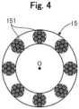
- Fig. 4 is an explanatory diagram illustrating a transverse sectional configuration of the coil body 15 taken along line B-B in Fig. 2 .
- the coil body 15 is conductive and arranged to surround a part of the distal end side of the core shaft 14.
- the coil body 15 is arranged to surround each of the whole of the small diameter portion 141 and a part of the distal end-side of the first tapered portion 142.
- the coil body 15 is a multi-thread twisted wire coil formed by winding, in a multi-thread pattern, a plurality of twisted wires 151 composed of a plurality of strands twisted together.
- the coil body 15 may be a single-thread coil formed by winding one strand in a single-thread pattern, or a multi-thread coil formed by winding a plurality of strands in a multi-thread pattern, or a single-thread twisted wire coil formed by winding, in a single-thread pattern, a twisted wire composed of a plurality of strands twisted together.
- the distal end of the coil body 15 is fixed together with the distal end of the core shaft 14 by the first electrode 11.
- the proximal end of the coil body 15 is fixed together with a part of the core shaft 14 (specifically, the first tapered portion 142) by a fixation portion 152.
- the fixation portion 152 is a member that fixes the coil body 15 and the core shaft 14.
- the fixation portion 152 can be formed by brazing with a hard braze such as silver braze and gold braze.
- the fixation portion 152 may be formed by welding the coil body 15 with the core shaft 14 by laser welding or the like.
- the covering portion 17 is a member that insulates the coil body 15 and a part or the whole of the core shaft 14 from the outside.
- the covering portion 17 is insulating and is arranged to cover the outer peripheral surface of the coil body 15 and the outer peripheral surface of the core shaft 14 located on a more proximal end side relative to the coil body 15.
- the covering portion 17 has an almost columnar shape with an outer diameter substantially constant from the distal end to the proximal end.
- the distal end of the covering portion 17 is fixed together with the distal end of the core shaft 14 by the first electrode 11.
- the proximal end portion of the covering portion 17 is joined with the proximal end portion of the core shaft 14.
- the covering portion 17 and the core shaft 14 can be joined using any bonding agent, for example, a metal solder such as silver braze, gold braze, zinc, Sn-Ag alloy, Au-Sn alloy, or an adhesive such as an epoxy adhesive.
- a gap may be formed between the covering portion 17 and the core shaft 14.
- the covering portion 17 may have an almost hollow-cylindrical shape with an outer diameter substantially constant from the distal end to the proximal end. No gap may be formed between the covering portion 17 and the core shaft 14 such that the inner peripheral surface of the covering portion 17 and the outer peripheral surface of the core shaft 14 are in contact with each other.
- the distal end marker 122 is insulating and colored in any color, and functionally serves as a marker for indicating the position of the first electrode 11.
- the distal end marker 122 is an annular member arranged to surround the outer peripheral surface of the covering portion 17 on the distal end portion of the covering portion 17.
- the connector 18 is located on the most proximal end side of the plasma guide wire 1, and is used by an operator to grasp the plasma guide wire 1.
- the cable 19 electrically connected to the core shaft 14 extends from the connector 18.
- the cable 19 is a conductive electric wire.
- the plasma guide wire 1 has a distal end load of 0.3 gf or higher and 20.0 gf or lower.
- the distal end load means the maximum force applied to a lesion when the guide wire is pressed against the lesion.
- the distal end load of the plasma guide wire 1 can be defined as a weight measured when the distal end of the plasma guide wire 1 is pressed against a precision scale.
- the first electrode 11 may be made of any conductive material, such as a chromium-molybdenum steel, a nickel-chromium-molybdenum steel, a stainless steel such as SUS304, and a nickel-titanium alloy.
- the first electrode 11 may be formed by melting the distal end portion of the core shaft 14 by laser or the like. In this case, the first electrode 11 is formed as a part of the distal end of the core shaft 14 (in other words, a part of the distal end of the core shaft 14 functionally serves as the first electrode 11).
- the core shaft 14 may be made of any conductive material, such as a chromium-molybdenum steel, a nickel-chromium-molybdenum steel, a stainless steel such as SUS304, and a nickel-titanium alloy.
- the coil body 15 may be made of any conductive material, such as a stainless steel such as SUS304, a nickel-titanium alloy, and an alloy containing gold, platinum, or tungsten, which are X-ray opaque materials.
- the covering portion 17 and the distal end marker 122 may be made of any insulating material, such as a copolymer of ethylene tetrafluoride and perfluoroalkoxy ethylene (PFA), a polyolefin such as polyethylene, polypropylene, and ethylene-propylene copolymer, a polyester such as polyethylene terephthalate, a thermoplastic resin such as polyvinyl chloride, ethylene-vinyl acetate copolymer, crosslinked ethylene-vinyl acetate copolymer, and polyurethane, a polyamide elastomer, a polyolefin elastomer, a silicone rubber, a latex rubber, and a super engineering plastic such as polyetheretherketone, polyetherimide, polyamideimide, polysulfone, polyimide, polyethersulfone.
- PFA perfluoroalkoxy ethylene
- a polyolefin such as polyethylene, polypropylene, and
- the RF generator 3 is a device that outputs a high frequency electric power between the first terminal 31 and a second terminal 32.
- the first terminal 31 is electrically connected to the catheter 2 via a first cable 33 and a first cable connector 34.
- the second terminal 32 is electrically connected to the plasma guide wire 1 via a second cable 35 and a second cable connector 36.
- the first cable 33 and the second cable 35 are conductive electric wires.
- the first cable connector 34 and the second cable connector 36 are connection terminals for physically and electrically connecting cables to each other.
- the high frequency electric power output from the first terminal 31 is transmitted to the second electrode 23 through the first cable 33, the first cable connector 34, the cable 25, the proximal end-side electrode 24, and the connection portion 213.
- the high frequency electric power output from the second terminal 32 is transmitted to the first electrode 11 through the second cable 35, the second cable connector 36, the cable 19, and the core shaft 14.
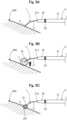
- Figs. 5A to 5C are explanatory diagrams illustrating a manner of ablation.
- Fig. 5A illustrates a state in which the plasma guide wire 1 and the catheter 2 are delivered to the vicinity of the CTO 200.
- Fig. 5B illustrates a state in which ablation is not correctly performed.
- Fig. 5C illustrates a state in which ablation is correctly performed.
- the operator delivers the catheter 2 to the vicinity of the CTO 200, and then outputs the high frequency electric power from the RF generator 3 in a state in which the first electrode 11 of the plasma guide wire 1 is protruded from the distal end opening 21a of the catheter 2 and positioned in the vicinity of the CTO 200. Then, the potential difference between the first electrode 11 of the plasma guide wire 1 and the second electrode 23 of the catheter 2 causes a streamer corona discharge between the first electrode 11 and the second electrode 23. This streamer corona discharge makes it possible to ablate the CTO 200 (living body tissue) in the vicinity of the first electrode 11 of the plasma guide wire 1.
- the plasma guide wire 1 In ablation using the plasma stream, energy emitted from the first electrode 11 excites the environment surrounding the living body tissue, so that plasma and vapor are generated, and the energy causes the living body tissue to evaporate. Thereby, during the ablation, a vapor layer accompanied by a shock wave or cavitation (bubbles generated by a pressure difference in a liquid) is generated around the electrode, causing the surrounding substances to vibrate.
- the plasma guide wire 1 according to the first embodiment has a distal end load of 0.3 gf or higher and 20.0 gf or lower and is flexible. Thus, when a conventional high frequency electric power is output from the RF generator 3, the distal end portion of the plasma guide wire 1 bounces due to the vibration caused by a vapor layer VL as illustrated in Fig. 5B , and therefore the CTO 200 cannot be correctly ablated.
- the high frequency electric power output from the RF generator 3 is set to the following discharge condition a1 or discharge condition a2.
- the discharge condition a2 is more preferable than the discharge condition a1.
- the size of the vapor layer VL can be made smaller than before, and an output power sufficient for ablation can be obtained.
- a hole 201 can be formed in the CTO 200.
- Fig. 6 is an explanatory diagram illustrating pulse modulation in the RF generator 3.
- Fig. 6 illustrates an example of a case where a pulse with a pulse width pa of 2 ⁇ s and a pulse interval pi modulated to 14 ⁇ s is defined as one pulse, which is repeated n times (n is a natural number).
- an alternating current (AC) pulse as illustrated in Fig. 6 is used.
- AC alternating current
- the following description explains a reason why it is preferable to adopt the discharge electric power and the duty ratio (pa/(pa+pi) ⁇ 100) in the aforementioned discharge conditions a1 and a2 in the RF generator 3 according to the first embodiment.
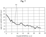
- Fig. 7 is a graph presenting a result of a test on the size of the vapor layer.
- the discharge conditions of the RF generator 3 were set to discharge conditions b1 to b3 below.
- Figs. 8A, 8B , 9A, and 9B are explanatory diagrams illustrating a method of a test on the ablation effect.
- Fig. 8A illustrates a state of the plasma guide wire 1 before ablation.
- Fig. 8B illustrates a state of the plasma guide wire 1 after ablation.
- Fig. 9A is a diagram illustrating a hole 302 formed on an alternative model 300 viewed from above.
- Fig. 9B is a cross-sectional view of the hole 302 formed on the alternative model 300.
- the alternative model 300 of a living body tissue made of a urethane sponge and physiological saline simulating a body fluid are prepared.
- the alternative model 300 is immersed in physiological saline.
- the first electrode 11 is brought into contact with a surface 301 of the alternative model 300 while the distal end side of the plasma guide wire 1 is protruded from the distal end opening 21a of the catheter 2.
- an angle ⁇ between the central axis O of the catheter 2 and the surface 301 of the alternative model 300 is set to 10 degrees.
- a straight-line distance L1 between the first electrode 11 of the plasma guide wire 1 and the second electrode 23 of the catheter 2 is set to 10 mm.
- the distal end side of the plasma guide wire 1 is preshaped.
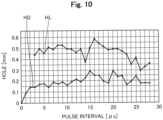
- a high frequency electric power was output from the RF generator 3 while varying the pulse interval pi, and each hole 302 formed on the alternative model 300 was examined. Specifically, for each of a plurality of holes 302 formed on the alternative model 300, a diameter HL and a depth HD of the hole 302 were measured. As illustrated in Fig. 9A , as the diameter HL of the hole 302, a length of a part where the diameter of the hole 302 formed on the surface 301 was largest was measured. As illustrated in Fig. 9B , as the depth HD of the hole 302, a length from the surface 301 on a part where the depth of the hole 302 was largest was measured.
- Fig. 10 is a graph presenting a result of a test on the ablation effect.
- a transition of the diameter HL of the hole 302 as measured by the method described in Figs. 8A, 8B , 9A, and 9B is represented by a dashed line
- a transition of the depth HD of the hole 302 is represented by a solid line.
- the ordinate represents the measured value (mm) of the hole 302
- the abscissa represents the value ( ⁇ s) of the pulse interval pi.
- Fig. 10 shows that, when the pulse interval pi is within a range of 13 ⁇ s or more and 25 ⁇ s or less, the diameter HL and the depth HD of the hole 302 are relatively larger than those at the other pulse intervals.
- Fig. 11A, 11B, and 11C are explanatory diagrams illustrating a method of an evaluation test on an effectiveness of catching the guide wire.
- Fig. 11A illustrates a state of ablation.
- Fig. 11B illustrates a state in which the distal end portion of the plasma guide wire 1 is caught by the hole 302 formed by ablation.
- Fig. 11C illustrates a state in which the distal end portion of the plasma guide wire 1 is not caught by the hole 302 formed by ablation.
- the plasma guide wire 1 inserted into the blood vessel may be affected by the blood flow, fine vibration of hands, or the like and therefore move on the distal end portion as illustrated in Figs 11B and 11C .
- the distal end portion of the plasma guide wire 1 is caught by the hole 302, displacement of the distal end portion is suppressed to facilitate opening of the CTO 200.
- the distal end portion of the plasma guide wire 1 is not caught by the hole 302, the distal end portion is displaced, and it takes labor and time to open the CTO 200.
- the hole 302 formed by ablation has a size and depth enough to catch the distal end portion of the plasma guide wire 1 as illustrated in Fig. 11B .
- Fig. 12 is a graph presenting a result of the evaluation test on the effectiveness of catching the guide wire.
- Fig. 12 presents a result of the effectiveness evaluation for each pulse interval pi, in which a case where the distal end portion of the plasma guide wire 1 was caught is rated as "A", or a case where the distal end portion of the plasma guide wire 1 was not caught is rated as "B".
- Fig. 12 shows that, when the pulse interval pi is within a range of 3 ⁇ s or more and 25 ⁇ s or less, the guide wire 1 is caught to facilitate the opening of the CTO 200 even if the angle between the catheter 2 and the alternative model 300 is shallow, e.g. the angle ⁇ is 10 degrees.
- Fig. 13 is an explanatory diagram presenting a range of a pulse interval based on the results of the test on the ablation effect and of the evaluation test on the effectiveness of catching the guide wire.
- the result of the evaluation test on the effectiveness of catching the guide wire shows that the effect can be obtained when the pulse interval pi is within a range of 3 ⁇ s or more and 25 ⁇ s or less ( Fig. 13 : within the dashed line box).
- the effectiveness is particularly high.
- the duty ratio is determined by dividing the pulse width pa by the total of the pulse width pa and the pulse interval pi and multiplying this quotient by 100 (pa/(pa+pi) ⁇ 100). Consequently, it can be seen that, under the discharge condition for the RF generator 3, the effect can be obtained when the duty ratio is 7.4% or higher and 40.0% or lower ( Fig. 13 : within the dashed line box, discharge condition a1). Also, it is found that, under the discharge condition for the RF generator 3, the effectiveness is particularly high when the duty ratio is 9.1% or higher and 13.0% or lower ( Fig. 13 : within the solid line box, discharge condition a2).
- Figs. 14A and 14B are explanatory diagrams presenting a result of a test on a discharge electric power.
- c1 and c2 described below were determined while varying the "discharge voltage" of the discharge condition b1 to 400 V, 600 V, 800 V, 1000 V, and 1200 V.
- the discharge conditions b2 and b3 were set as described above (b2: 2 ⁇ s, b3: 200) and the pulse interval pi was set to 14 ⁇ s.
- Fig. 14A presents a result of a test on the c1.
- Fig. 14A presents the size (mm) of the vapor layer VL for each voltage (V).
- the level of the voltage is proportional to the size of the vapor layer VL.
- the size of the vapor layer VL where the pulse interval pi is within a range that provides effectiveness is 0.75 mm or larger and 2.16 mm or smaller.
- the test result in Fig. 14A shows that, regarding the discharge voltage where the VL size is within the above range (range of the size of the vapor layer VL where the pulse interval pi is within the range that provides effectiveness), 400 V is too low, 800 V is too high, and 600 V is appropriate.
- Fig. 14B presents a result of a test on the c2.
- a curve indicating a relationship between the level of the resistance load and the electric power value is drawn for each voltage (V).
- the ordinate represents the electric power value (W) determined by the test on the c2
- the abscissa represents the level (ohms) of the resistance load of the resistor used in the test on the c2.
- Resistances of living body tissues and body fluids are generally 1000 ohms or lower.
- the discharge voltage is suitably higher than 400 V and lower than 800 V, and therefore around 600 V.
- the discharge electric power is preferably 50 W or higher and 100 W or lower.
- the results of each test described in Figs. 7A to 14B show that, in the plasma ablation system 100 according to the first embodiment including the plasma guide wire 1 more flexible than conventional devices, the high frequency electric power output from the RF generator 3 is set to the discharge condition a1 or discharge condition a2 described above, so that the ablation effect can be obtained while suppressing bouncing on the distal end portion of the plasma guide wire 1.
- the plasma ablation system 100 includes the plasma guide wire 1 including the conductive first electrode 11 formed on the distal end portion, and the catheter 2 including the conductive second electrode 23 formed on the distal end side.
- the CTO 200 living body tissue
- the RF generator 3 outputs a high frequency electric power that is 50 W or higher and 100 W or lower during discharge and pulse-modulated so as to have a duty ratio of 7.4% or higher and 40.0% or lower (discharge condition a1).
- the vapor layer VL generated around the first electrode 11 during ablation can be minimized to suppress flip-up on the distal end portion of the guide wire 1 accompanying vibration of the surrounding substances.
- safety can be improved in the plasma ablation system 100.
- the RF generator 3 may output a high frequency electric power pulse-modulated so as to have a duty ratio of 9.1% or higher and 13.0% or lower (discharge condition a2). Thereby, the size and the depth of the hole formed by ablation can be made larger, while minimizing the vapor layer VL during ablation to suppress the flip-up on the distal end portion of the plasma guide wire 1.
- the plasma guide wire 1 since the plasma guide wire 1 according to the first embodiment includes the conductive coil body 15 arranged to surround a part of the distal end side of the core shaft 14, the skin effect on the distal end side of the core shaft 14 can be reduced, and the distal end side of the core shaft 14 can be made thinner than the proximal end side. Since the plasma guide wire 1 includes the insulating covering portion 17 arranged to cover the outer periphery of the coil body 15, safety can be improved. As a result, the distal end side of the plasma guide wire 1 can be made more flexible, and safety of the plasma ablation system 100 can be improved.
- the plasma guide wire 1 according to the first embodiment has a distal end load of 0.3 gf or higher and 20.0 gf or lower, the distal end portion of the plasma guide wire 1 can be made flexible to improve safety. As a result, according to the first embodiment, the plasma guide wire 1 suitable for ablation using plasma stream can be provided.
- the catheter 2 includes the connection portion 213 that electrically connects the second electrode 23 formed on the distal end side with the proximal end-side electrode 24 formed on the proximal end side and is embedded in the main body portion 211 (thicker wall portion) of the catheter 2.
- the connection portion 213 that electrically connects the second electrode 23 formed on the distal end side with the proximal end-side electrode 24 formed on the proximal end side and is embedded in the main body portion 211 (thicker wall portion) of the catheter 2.
- Fig. 15 is an explanatory diagram illustrating a cross-sectional configuration of a plasma guide wire 1A according to the second embodiment.
- the plasma ablation system 100 according to the second embodiment includes the plasma guide wire 1A illustrated in Fig. 15 instead of the plasma guide wire 1 described in the first embodiment.
- the plasma guide wire 1A does not include the coil body 15 and the fixation portion 152 described in the first embodiment.
- the configuration of the plasma guide wire 1A can be variously modified, and the coil body 15 may be omitted.
- the plasma ablation system 100 including this plasma guide wire 1A according to the second embodiment can exhibit a similar effect to the first embodiment. Since the plasma guide wire 1A according to the second embodiment does not have the coil body 15, the distal end side of the plasma guide wire 1A can be made thinner and the number of components constituting the plasma guide wire 1A can be decreased to reduce the number of steps and the cost for manufacturing the plasma guide wire 1A.
- Fig. 16 is an explanatory diagram illustrating a method of a test on the interelectrode distance L1.
- the alternative model 300 of the living body tissue made of a urethane sponge and physiological saline simulating a body fluid are prepared, and the alternative model 300 is immersed in physiological saline.
- the first electrode 11 is brought into contact with the surface 301 of the alternative model 300 while the distal end side of the plasma guide wire 1 is protruded from the distal end opening 21a of the catheter 2.
- the first electrode 11 is brought into contact with the surface 301 such that a pushing depth D1 of the first electrode 11 against the surface 301 of the sample 300 is 1 mm.
- the pushing depth D1 means a difference in height between the surface 301 in the vicinity of the end portion of the alternative model 300 to which no force is applied from the first electrode 11 and the surface 301 of a part of the alternative model 300 which the first electrode 11 is in contact with, as illustrated in Fig. 16 .
- an angle between the central axis O of the catheter 2 and the surface 301 of the alternative model 300 was set to 10 degrees, and the distal end side of the plasma guide wire 1 was preshaped.
- the distal end load of the plasma guide wire 1 was set to 3.5 gf.
- a return electrode 41 of a return wire 4 was used instead of the second electrode 23 of the catheter 2.
- the plasma guide wire 1 according to the second embodiment is flexible with a distal end load of 0.3 gf or higher and 20.0 gf or lower, as described above.
- a supporting force (improved rigidity) applied by the catheter 2 may affect the evaluation result.
- the evaluation was conducted using the return electrode 41 of the return wire 4 instead of the second electrode 23 of the catheter 2.
- the conductive return electrode 41 is disposed on a distal end portion of a conductive coil body 42.
- a proximal end side of the coil body 42 is covered with a covering portion 43 made of an insulating resin.
- the evaluation was performed assuming that a straight-line distance L1a between the first electrode 11 of the plasma guide wire 1 and the return electrode 41 of the return wire 4 is the same as the straight-line distance L1 between the first electrode 11 of the plasma guide wire 1 and the second electrode 23 of the catheter 2 (i.e. the interelectrode distance L1).
- each of the holes 302 formed on the alternative model 300 was examined by outputting a high frequency electric power of 200 pulses 60 times from the RF generator 3 while varying the straight-line distance L1a between the first electrode 11 and the return electrode 41, under the aforementioned discharge conditions b1 to b3.
- Figs. 17A and 17B are diagrams illustrating a method for measuring the depth HD of the hole 302.
- Fig. 17A illustrates the alternative model 300 having the hole 302.
- Fig. 17B illustrates a state that the alternative model 300 is cut.
- the depth HD of the hole 302 is measured as follows. First, as illustrated in Fig. 17A , the alternative model 300 having the hole 302 is cut along the longitudinal direction of the hole 302 using a cutter 5. Subsequently, a crosssection of one of a cut piece 300a or 300b of the alternative model 300 is photographed using a digital microscope to obtain a cross-sectional image. The obtained cross-sectional image is analyzed using a well-known image processing software (e.g. imaged) to measure the depth HD of the hole 302.
- a well-known image processing software e.g. imaged
- the hole 302 formed in the alternative model 300 by ablation is not necessarily formed most deeply in a direction perpendicular to the surface 301 of the alternative model 300, but may be formed most deeply in a direction inclined to the surface 301 of the alternative model 300.
- the above measurement method makes it possible to accurately measure depths HD not only of the hole 302 perpendicular to the surface 301 of the alternative model 300 but also of the hole 302 inclined to the surface 301 of the alternative model 300.
- Fig. 18 is a graph presenting a result of the test on the interelectrode distance L1.
- the ordinate represents the depth (mm) of the hole 302
- the abscissa represents the interelectrode distance L1a (i.e. interelectrode distance L1).
- the bar RA in Fig. 18 represents a range of a standard deviation in the measurement result of the test performed multiple times (three times in this test) under the same condition
- the point CE represents a central point of the range of the standard deviation.
- the result in Fig. 18 shows that the interelectrode distance L1 of 10 mm or larger and 30 mm or smaller makes it possible to increase the depth HD of the hole 302.
- a preferable depth HD can be obtained for the hoe 302, when the interelectrode distance L1 is 10 mm or larger and 50 mm or smaller, which is a range used in routine procedures. From the test result presented in Fig. 18 , it is easy to predict that the depth HD of the hole 302 can be made deeper even when the interelectrode distance L1 is smaller than 10 mm.
- the distal tip 22 having a length of about several millimeters in the direction of the central axis O is disposed on the more distal end side relative to the second electrode 23.
- the interelectrode distance L1 is smaller than 10 mm, in light of the actual procedure in which ablation must be performed while recognizing that the first electrode 11 of the plasma guide wire 1 is definitely protruded from the distal tip 22 of the catheter 2 under X-ray fluoroscopy with poor visibility.
- both, rather than one, of the plasma guide wire 1 and the catheter 2 are advanced during ablation with plasma, and therefore it is difficult to assume that ablation is performed with the interelectrode distance L1 of longer than 50 mm.
- Fig. 19 is an explanatory diagram illustrating a method of a test on the electrode angle ⁇ .
- the alternative model 300 of the living body tissue made of an urethane sponge and physiological saline simulating a body fluid are prepared, and the alternative model 300 is immersed in physiological saline.
- the first electrode 11 is brought into contact with the surface 301 of the alternative model 300 such that the pushing depth D1 is 1 mm while the distal end side of the plasma guide wire 1 is protruded from the distal end opening 21a of the catheter 2.
- the plasma guide wire 1 with a distal end load of 3.5 gf was used, the straight-line distance L1 (interelectrode distance L1) between the first electrode 11 of the plasma guide wire 1 and the second electrode 23 of the catheter 2 was set to 10 mm, and the distal end side of the plasma guide wire 1 was preshaped such that the angle between the distal end side and the surface 301 was 45 degrees.
- a preshaped angle ⁇ 1 is an angle between the central axis O of the catheter 2 and the central axis O1 of the distal end portion of the plasma guide wire 1, as illustrated in Fig. 19 .
- each hole formed on the alternative model 300 was examined by outputting a high frequency electric power of 200 pulses 60 times from the RF generator 3 while varying the angle ⁇ (electrode angle ⁇ ) between the central axis O of the catheter 2 and the surface 301 of the alternative model 300 under the aforementioned discharge conditions b1 to b3.
- the angle ⁇ electrode angle ⁇
- the method described in Figs. 17A and 17B was used.
- Fig. 20 is a graph illustrating a result of the test on the electrode angle ⁇ .
- the ordinate represents the depth (mm) of the hole and the abscissa represents the electrode angle ⁇ .
- results obtained from three tests under the same condition are each plotted with black circles.
- the result in Fig. 20 shows that the larger the electrode angle ⁇ is, the larger the depth of the hole is, but a preferable hole depth can be obtained when the ⁇ is 10 degrees or larger and 50 degrees or smaller, which is a range of the electrode angle ⁇ used in routine procedures. It is difficult to assume that the electrode angle ⁇ is set to smaller than 10 degrees, considering that the plasma guide wire 1 and the catheter 2 are used in a blood vessel. Also, it is difficult to assume that the electrode angle ⁇ is set to larger than 50 degrees, considering that the distal end of the plasma guide wire 1 is generally preshaped.
- the results of the tests in Figs. 16 to 18 showed that, in the range of the interelectrode distance L1 used in routine procedures, a preferable effect could be obtained by setting the discharge condition for the RF generator 3 to the discharge condition a1 or the discharge condition a2 described in the first embodiment.
- the straight-line distance L1 (interelectrode distance L1) between the first electrode 11 of the plasma guide wire 1 and the second electrode 23 of the catheter 2 is set to 10 mm or longer and 50 mm or shorter, the depth of the hole formed in the living body tissue by ablation using the plasma guide wire 1 can be within a desirable range.
- the angle ⁇ 2 between the distal end portion of the plasma guide wire 1 and the living body tissue refers to an acute angle between the central axis O1 of the distal end portion of the plasma guide wire 1 and the surface of the living body tissue (in the example of Fig. 19 , the surface 301 of the alternative model 300), as illustrated in Fig. 19 .
- the configuration of the plasma ablation system 100 can be modified in various ways.
- other devices may be used instead of the catheter 2, such as a pad having an electrode corresponding to the second electrode, and a guide wire having an electrode corresponding to the second electrode.
- the plasma ablation system 100 may be composed of other input/output devices (e.g. foot switch, input/output touch panel, operating lever, operating button) and the like, not illustrated.
- the plasma ablation system 100 may comprise other examination devices (e.g. computerized tomography (CT) device, magnetic resonance imaging (MRI) device, X-ray imaging device, ultrasound imaging device, etc.) not illustrated.
- CT computerized tomography
- MRI magnetic resonance imaging
- X-ray imaging device X-ray imaging device
- ultrasound imaging device etc.
- the configuration of the plasma guide wire 1 can be modified in various ways.
- the distal end load of the plasma guide wire 1 may be lower than 0.3 gf and higher than 20.0 gf.
- the configuration of the core shaft 14 described above is merely an example, and at least a part of the small diameter portion 141, the first tapered portion 142, and the second tapered portion 143 may be omitted.
- the shape of the first electrode 11 can be changed arbitrarily and can be any shape such as an arrowhead shape, a spherical shape, a columnar shape, and a polygonal columnar shape.
- the distal end marker 122 and the proximal end-side electrode 24 may be omitted.
- Fig. 1 illustrates, as the catheter 2, a so-called OTW type (over-the-wire type) catheter having openings on the distal and proximal ends of the shaft portion 21.
- the catheter 2 may be a so-called Rx type (rapid exchange type) catheter having a port (opening) for rapidly inserting and removing devices such as a delivery guide wire and the plasma guide wire 1.
- the port can be a through-hole that communicates between the outside and the inside of the lumen 21L at any position between the distal end and the proximal end of the shaft portion 21.
- the catheter 2 may be configured as a multi-lumen catheter including a plurality of lumens.
- the configurations of the plasma guide wires 1 and 1A and the catheter 2 according to the first and second embodiments, and the configurations of the plasma guide wires 1 and 1A and the catheter 2 according to the modification examples 1 to 3 may be combined as appropriate.
Landscapes
- Health & Medical Sciences (AREA)
- Surgery (AREA)
- Engineering & Computer Science (AREA)
- Life Sciences & Earth Sciences (AREA)
- Biomedical Technology (AREA)
- Molecular Biology (AREA)
- Nuclear Medicine, Radiotherapy & Molecular Imaging (AREA)
- Plasma & Fusion (AREA)
- Physics & Mathematics (AREA)
- Heart & Thoracic Surgery (AREA)
- Medical Informatics (AREA)
- Otolaryngology (AREA)
- Animal Behavior & Ethology (AREA)
- General Health & Medical Sciences (AREA)
- Public Health (AREA)
- Veterinary Medicine (AREA)
- Cardiology (AREA)
- Surgical Instruments (AREA)
- Media Introduction/Drainage Providing Device (AREA)
Abstract
Description
- The present invention relates to a plasma ablation system and a plasma guide wire.
- In recent years, ablation treatments have become known as treatment methods for arrhythmias or the like that cause an abnormal beating rhythm of the heart. For example,
Patent Literatures 1 to 5 disclose devices and systems that can be used in such ablation treatments, in which a living body tissue (a part causing arrhythmia) is excised by using a plasma stream. - In the ablation using the plasma stream, energy emitted from an electrode is absorbed by a living body tissue, and the living body tissue reaching a temperature above a boiling point is ejected as vapor or plasma. It is known that, for that reason, a vapor layer accompanied by a shock wave or cavitation (bubbles generated by a pressure difference in a liquid) is generated around the electrode, causing the surrounding substances to vibrate during ablation. In this regard, in the devices and systems described in
Patent Literatures 1 to 5, an electrode that emits energy is disposed on a highly rigid member such as a puncture device, a probe, a cutting electrode, and a conductive blade, so that a configuration is obtained that can withstand vibration during ablation. -
- Patent Literature 1:
US Patent No. 9179932 - Patent Literature 2:
JP 2006-517843 W - Patent Literature 3:
US Patent No. 6135998 - Patent Literature 4:
US Patent No. 6780178 - Patent Literature 5:
JP 2018-524132 W - Incidentally, in case of chronic total occlusion (CTO), an inside of a vessel may be occluded by a lesion. In such a case, it is needed to ablate the lesion to facilitate opening of the CTO. However, in the devices and systems described in
Patent Literatures 1 to 5, the rigidities of members (puncture device, probe, cutting electrode, conductive blade, etc.) equipped with an electrode are higher than that of a guide wire. Thus, there has been a problem that it is undesirable to push the puncture device or the like described inPatent Documents 1 to 5 forward to a lesion in a complicatedly curved blood vessel, from the viewpoint of safety. This problem is common to general devices or systems for ablation treatment because the device can not only be inserted in a blood vessel system, but also an organism lumen such as a lymph gland system, a biliary tract system, a urinary tract system, a respiratory tract system, a digestive organ system, a secretory gland, and a genital organ. - The present invention has been made in order to solve at least a part of the above-described problem, and an object of the present invention is to improve safety in the plasma ablation system.
- The present invention has been made in order to solve at least a part of the above-described problem and can be embodied as the following aspects.
- (1) An aspect of the present invention provides a plasma ablation system. The plasma ablation system includes a plasma guide wire having an elongated external shape and including a conductive first electrode formed on a distal end portion, a catheter having an elongated external shape and including a conductive second electrode formed on a distal end side and a lumen through which the plasma guide wire is inserted, and a radio frequency (RF) generator electrically connected to each of the plasma guide wire and the catheter to output a high frequency electric power to the first electrode and the second electrode, in which the plasma guide wire can ablate a living body tissue by discharge between the first electrode and the second electrode, and the RF generator outputs the high frequency electric power that is 50 W or higher and 100 W or lower during discharge and is pulse-modulated so as to have a duty ratio of 7.4% or higher and 40.0% or lower.
According to this configuration, the plasma ablation system includes the plasma guide wire having the conductive first electrode formed on the distal end portion, and the catheter having the conductive second electrode formed on the distal end side. Thus, as a result of outputting the high frequency electric power to the first electrode and the second electrode while the plasma guide wire is inserted through the catheter, the living body tissue can be ablated using an energy emitted by the discharge between the first electrode and the second electrode. The RF generator outputs the high frequency electric power that is 50 W or higher and 100 W or lower during discharge and is pulse-modulated so as to have a duty ratio of 7.4% or higher and 40.0% or lower. Thus, for example, even when the first electrode is disposed on a guide wire more flexible (lower rigidity) than conventional configurations of a puncture device, a probe, a cutting electrode, a conductive blade, and the like, the vapor layer generated around the first electrode during ablation can be minimized to suppress bouncing on the distal end portion of the plasma guide wire accompanying vibration of the surrounding substances. As a result, this configuration makes it possible to improve safety in the plasma ablation system. - (2) The plasma ablation system according to the above aspect may be configured such that the RF generator outputs the high frequency electric power pulse-modulated so as to have a duty ratio of 9.1% or higher and 13.0% or lower.
According to this configuration, the RF generator outputs the high frequency electric power pulse-modulated so as to have a duty ratio of 9.1% or higher and 13.0% or lower. Thereby, a size and a depth of a hole formed by ablation can be made larger, while minimizing the vapor layer during ablation to suppress bouncing on the distal end portion of the plasma guide wire. - (3) The plasma ablation system according to the above aspects may be configured such that the plasma guide wire has a distal end load of 0.3 gf or higher and 20.0 gf or lower.
According to this configuration, since the plasma guide wire has a distal end load of 0.3 gf or higher and 20.0 gf or lower, the distal end portion of the plasma guide wire can be made flexible to improve safety. - (4) The plasma ablation system according to the above aspects may be configured such that the plasma guide wire includes, in addition to the first electrode, a conductive core shaft having an elongated external shape, a conductive coil body arranged to surround a part of the distal end side of the core shaft, and an insulating covering portion arranged to cover an outer periphery of the coil body, in which the first electrode fixes the distal end of each of the core shaft, the coil body, and the covering portion.
According to this configuration, since the plasma guide wire includes the conductive coil body arranged to surround a part of the distal end side of the core shaft, a skin effect on the distal end side of the core shaft can be reduced, and the distal end side of the core shaft can be made thinner than the proximal end side. Since the plasma guide wire includes the insulating covering portion arranged to cover the outer periphery of the coil body, safety can be improved. As a result, the distal end side of the plasma guide wire can be made more flexible, and safety of the plasma ablation system can be improved. - (5) The plasma ablation system according to the above aspects may be configured such that the catheter includes, in addition to the second electrode, a conductive proximal end-side electrode formed on the proximal end side of the catheter and electrically connected to the RF generator, and a conductive connection portion that electrically connects the second electrode with the proximal end-side electrode and is embedded in a thick wall portion of the catheter.
According to this configuration, the catheter includes the connection portion that electrically connects the second electrode formed on the distal end side with the proximal end-side electrode formed on the proximal end side, and is embedded in the thick wall portion of the catheter. Thereby, it is possible to prevent obstruction of the operation due to the connection portion entangled with the outer peripheral surface of the catheter, and obstruction of the operation due to the connection portion entangled with the plasma guide wire inserted through the catheter, compared to a case where the connection portion is exposed to the outside or inside of the catheter. As a result, the operability of the plasma ablation system can be improved. - (6) The plasma ablation system according to the above aspects may be configured such that the catheter further includes a mesh-shaped reinforcement portion made of mesh-woven strands and embedded in the thick wall portion of the catheter.
According to this configuration, since the catheter further includes a mesh-shaped reinforcement portion made of mesh-woven strand, deflection of the catheter can be prevented to improve shape retainability of the catheter. - (7) The plasma ablation system according to the above aspects may be configured such that a straight-line distance between the first electrode of the plasma guide wire and the second electrode of the catheter is 10 mm or longer and 50 mm or shorter.
According to this configuration, since the straight-line distance between the first electrode of the plasma guide wire and the second electrode of the catheter is 10 mm or longer and 50 mm or shorter, the depth of the hole formed in the living body tissue by ablation can be within a desirable range. - (8) According to an aspect of the present invention, a plasma guide wire is provided. This plasma guide wire includes a conductive core shaft having an elongated external shape, a conductive coil body arranged to surround a part of a distal end side of the core shaft, an insulating covering portion arranged to cover an outer periphery of the coil body, and a conductive first electrode that fixes each distal end of the core shaft, the coil body, and the covering portion, in which the plasma guide wire has a distal end load of 0.3 gf or higher and 20.0 gf or lower.
According to this configuration, since, in the plasma guide wire, the skin effect on the distal end side of the core shaft can be reduced by the conductive coil body, the distal end side of the core shaft can be made thinner than the proximal end side, and the distal end side of the plasma guide wire can be made flexible. Also, safety can be improved by the insulating covering portion arranged to cover the outer periphery of the coil body. As a result, this configuration makes it possible to provide a plasma guide wire suitable for ablation using a plasma stream. - (9) The plasma guide wire according to the above aspect may be configured such that the plasma guide wire has a preshaped distal end portion.
- According to this configuration, since the plasma guide wire has the preshaped distal end portion, an angle between the distal end portion of the plasma guide wire and a living body tissue can be increased compared to a case without preshaping. As a result, a depth of a hole formed on the living body tissue by ablation can be within a desirable range.
- The present invention can be embodied in various manners, such as a plasma guide wire, an RF generator, a plasma ablation system equipped with a plasma guide wire and an RF generator, a method for manufacturing these devices and systems, a method for controlling an RF generator in outputting a high frequency electric power to these devices and systems, and a computer program.
-
-
Fig. 1 is a schematic diagram illustrating an overall configuration of a plasma ablation system. -
Fig. 2 is an explanatory diagram illustrating a transverse sectional configuration of a catheter taken along line A-A inFig. 1 . -
Fig. 3 is an explanatory diagram illustrating a cross-sectional configuration of a plasma guide wire. -
Fig. 4 is an explanatory diagram illustrating a transverse sectional configuration of a coil body taken along line B-B inFig. 2 . -
Figs. 5A to 5C are explanatory diagrams illustrating a manner of ablation. -
Fig. 6 is an explanatory diagram illustrating pulse modulation in an RF generator. -
Fig. 7 is a graph presenting a result of a test on a size of a vapor layer. -
Figs. 8A and 8B are explanatory diagrams illustrating a method of a test on an ablation effect. -
Figs. 9A and 9B are explanatory diagrams illustrating the method of the test on the ablation effect. -
Fig. 10 is a graph presenting a result of the test on the ablation effect. -
Figs. 11A to 11C are explanatory diagrams illustrating a method of an evaluation test on an effectiveness of catching the guide wire. -
Fig. 12 is a graph presenting a result of the evaluation test on the effectiveness of catching the guide wire. -
Fig. 13 is an explanatory diagram presenting a range of a pulse interval based on the results of the test on the ablation effect and the evaluation test on the effectiveness of catching the guide wire. -
Figs. 14A and 14B are explanatory diagrams presenting a result of a test on a discharge electric power. -
Fig. 15 is an explanatory diagram illustrating a cross-sectional configuration of a plasma guide wire according to the second embodiment. -
Fig. 16 is an explanatory diagram illustrating a method of a test on an interelectrode distance. -
Figs. 17A and 17B are diagrams illustrating a method for measuring a depth of a hole. -
Fig. 18 is a graph presenting a result of the test on the interelectrode distance. -
Fig. 19 is an explanatory diagram illustrating a method of a test on an electrode angle. -
Fig. 20 is a graph presenting a result of the test on the electrode angle. -
Fig. 1 is a schematic diagram illustrating an overall configuration of aplasma ablation system 100. Theplasma ablation system 100 is used for the purpose of opening a chronic total occlusion (CTO), and treating mild to moderate stenosis, significant stenosis, arrhythmia, or the like by ablating a living body tissue. Theplasma ablation system 100 includes aplasma guide wire 1, acatheter 2, and anRF generator 3. Theplasma ablation system 100 will be explained below in a case of using theplasma ablation system 100 for the purpose of opening a CTO in a blood vessel as an example, but theplasma ablation system 100 can be used so as to be inserted into not only a blood vessel system, but also an organism lumen such as a lymph gland system, a biliary tract system, a urinary tract system, a respiratory tract system, a digestive organ system, a secretory gland, and a genital organ. - In
Fig. 1 , an axis that passes through centers of theplasma guide wire 1 and thecatheter 2 in theplasma ablation system 100 is represented by an axis line O (dot and dash line). In the example ofFig. 1 , the axis line O coincides with each of the axes that pass through the center of theplasma guide wire 1 excluding a part of the distal end side and the center of thecatheter 2. However, the axis line O may be inconsistent with each central axis of theplasma guide wire 1 and thecatheter 2.Fig. 1 illustrates X-, Y-, and Z-axes orthogonal to each other. The X-axis corresponds to a longitudinal direction of theplasma guide wire 1 and thecatheter 2, the Y-axis corresponds to a height direction of theplasma guide wire 1 and thecatheter 2, and the Z-axis corresponds to a width direction of theplasma guide wire 1 and thecatheter 2. Hereinafter, the left side (- X-axis direction) inFig. 1 is referred to as a "distal end side" of theplasma guide wire 1, thecatheter 2, and each constitution component, and the right side (+ X-axis direction) inFig. 1 is referred to as a "proximal end side" of theplasma guide wire 1, thecatheter 2, and each constitution component. One end of the both ends in the longitudinal direction (X-axis direction) which is positioned on the distal end side is referred to as a "distal end", and the other end positioned on the proximal end side is referred to as a "proximal end". The distal end and the vicinity thereof are referred to as a "distal end portion", and the proximal end and the vicinity thereof are referred to as a "proximal end portion". The distal end side is inserted into an inside of a living body, and the proximal end side is operated by an operator such as a surgeon. These points are also true for figures followingFig. 1 . - The
plasma guide wire 1 has an elongated external shape and includes a conductivefirst electrode 11 formed on the distal end portion. The detailed configuration of theplasma guide wire 1 is described below. As illustrated inFig. 1 , theplasma guide wire 1 is used so as to be inserted through alumen 21L (Fig. 2 ) of thecatheter 2. - The
catheter 2 has an elongated external shape and has a conductivesecond electrode 23 formed on the distal end side and thelumen 21L through which theplasma guide wire 1 is inserted. As illustrated inFig. 1 , thecatheter 2 according to the first embodiment includes ashaft portion 21, adistal tip 22, thesecond electrode 23, a proximal end-side electrode 24, and acable 25. InFig. 1 , thesecond electrode 23 and the proximal end-side electrode 24 are hatched with shaded lines to distinguish them from other members. -
Fig. 2 is an explanatory diagram illustrating a transverse sectional configuration of thecatheter 2 taken along line A-A inFig. 1 . As illustrated inFig. 2 , theshaft portion 21 includes amain body portion 211, areinforcement portion 212, and aconnection portion 213. - The
main body portion 211 is a member that constitutes a thick wall portion of thecatheter 2 and also insulates between thereinforcement portion 212 and theconnection portion 213. Themain body portion 211 has an almost hollow-cylindrical shape with openings on both ends. An inner cavity of themain body portion 211 functionally serves as thelumen 21L through which theplasma guide wire 1 is inserted. Hereinafter, the opening on the proximal end side of themain body portion 211 is also referred to as "proximal end opening 21b". An outer diameter and a length of themain body portion 211 can be arbitrarily determined. At least one of an outer peripheral surface and an inner peripheral surface of themain body portion 211 may be coated with a hydrophilic or hydrophobic resin. In this case, each of the outer and inner peripheral surfaces of themain body portion 211 may be coated with different types of resins or a same resin. - The
reinforcement portion 212 is a member for reinforcing themain body portion 211. Thereinforcement portion 212 has a mesh shape and is made of conductive strands woven into a mesh. Thereinforcement portion 212 is embedded more inside relative to theconnection portion 213 in themain body portion 211. Thisreinforcement portion 212 makes it possible to suppress deflection of thecatheter 2 to improve the shape retainability of thecatheter 2. Thecatheter 2 may be configured without thereinforcement portion 212. - The
connection portion 213 is conductive and electrically connects thesecond electrode 23 with the proximal end-side electrode 24. Theconnection portion 213 has a coil shape and is made of conductive strands spirally wound along a circumferential direction of theshaft portion 21. Theconnection portion 213 is embedded more outside relative to thereinforcement portion 212 in themain body portion 211. The distal end portion of theconnection portion 213 is electrically connected to thesecond electrode 23. The proximal end portion of theconnection portion 213 is electrically connected to the proximal end-side electrode 24. In other words, thesecond electrode 23, the proximal end-side electrode 24, and theconnection portion 213 constitute one conductor in thecatheter 2. Theconnection portion 213 may be a single-thread coil formed by winding one strand in a single-thread pattern, a multi-thread coil formed by winding a plurality of strands in a multi-thread pattern, a single-thread twisted wire coil formed by winding, in a single-thread pattern, a twisted wire composed of a plurality of strands twisted together, or a multi-thread twisted wire coil formed by winding, in a multi-thread pattern, a plurality of twisted wires composed of a plurality of strands twisted together. - The
distal tip 22 is disposed on the most distal end side of the catheter 2 (i.e. the distal end portion of the catheter 2). Thedistal tip 22 has an external shape whose diameter is gradually reduced from the proximal end side to the distal end side in order to facilitate advancement of thecatheter 2 inside the blood vessel. Thedistal tip 22 has a through-hole penetrating through thedistal tip 22 in the direction of the axis line O. This through-hole communicates with thelumen 21L of theshaft portion 21. Hereinafter, the opening on the distal end side of the through-hole in thedistal tip 22 is also referred to as "distal end opening 21a". An outer diameter and a length of thedistal tip 22 can be arbitrarily determined. - The
second electrode 23 is conductive and discharges electricity together with thefirst electrode 11 of theplasma guide wire 1. Thesecond electrode 23 is an annular member arranged to surround the outer peripheral surface of theshaft portion 21 on the distal end of theshaft portion 21. The proximal end-side electrode 24 is conductive and is electrically connected to afirst terminal 31 of theRF generator 3 via thecable 25. The proximal end-side electrode 24 is an annular member arranged to surround the outer peripheral surface of theshaft portion 21 on a part of the proximal end side of theshaft portion 21. Lengths of thesecond electrode 23 and the proximal end-side electrode 24 can be arbitrarily determined. Thecable 25 is a conductive electric wire. Thecable 25 is connected to the proximal end-side electrode 24. - The
main body portion 211 may be made of any insulating material, e.g. a polyolefin such as polyethylene, polypropylene, and ethylene-propylene copolymer, a polyester such as polyethylene terephthalate, a thermoplastic resin such as polyvinyl chloride, ethylene-vinyl acetate copolymer, crosslinked ethylene-vinyl acetate copolymer, and polyurethane, a polyamide elastomer, a polyolefin elastomer, a polyurethane elastomer, a silicone rubber, and a latex rubber. Preferably, thedistal tip 22 is flexible and can be made of e.g. a resin material such as polyurethane and polyurethane elastomer. - Each of the
reinforcement portion 212, theconnection portion 213, thesecond electrode 23, and the proximal end-side electrode 24 may be made of any material as long as it is conductive. Examples of the material include a stainless steel such as SUS316 and SUS304, a nickel-titanium alloy, an alloy containing gold, platinum, or tungsten, which are X-ray opaque materials, and the like. Thereinforcement portion 212, theconnection portion 213, thesecond electrode 23, and the proximal end-side electrode 24 may be made of the same material or of different materials. -
Fig. 3 is an explanatory diagram illustrating a cross-sectional configuration of theplasma guide wire 1. As illustrated inFigs. 1 and3 , theplasma guide wire 1 according to the first embodiment includes thefirst electrode 11, acore shaft 14, acoil body 15, a coveringportion 17, adistal end marker 122, a connector 18 (Fig. 1 ), and a cable 19 (Fig. 1 ). - The
first electrode 11 is conductive and discharges electricity together with thesecond electrode 23 of thecatheter 2. Thefirst electrode 11 is disposed on the most distal end side of the plasma guide wire 1 (i.e. the distal end portion of the plasma guide wire 1). Thefirst electrode 11 has an external shape with a diameter gradually reduced from the proximal end side to the distal end side in order to facilitate advancement of theplasma guide wire 1 inside the blood vessel. Thefirst electrode 11 fixes each distal end of thecore shaft 14, the coveringportion 17, and thecoil body 15. Thefirst electrode 11 is joined to each distal end of thecore shaft 14 and thecoil body 15 by laser welding or the like. - The
core shaft 14 is a conductive member constituting the central axis of theplasma guide wire 1. Thecore shaft 14 has an elongated external shape extending in a longitudinal direction of theplasma guide wire 1. Thecore shaft 14 includes asmall diameter portion 141, a firsttapered portion 142, a secondtapered portion 143, and alarge diameter portion 144 in this order from the distal end to the proximal end. Thesmall diameter portion 141 is a part where an outer diameter of thecore shaft 14 is smallest, and has an almost columnar shape with an outer diameter substantially constant from the distal end to the proximal end. The firsttapered portion 142 is disposed between thesmall diameter portion 141 and the secondtapered portion 143, and has an external shape with a diameter gradually reduced from the proximal end side to the distal end side. The secondtapered portion 143 is disposed between the firsttapered portion 142 and thelarge diameter portion 144, and has an external shape with an outer diameter gradually reduced from the proximal end side to the distal end side at a taper angle different from that of the firsttapered portion 142. Thelarge diameter portion 144 is a part where the outer diameter of thecore shaft 14 is largest, and has an almost columnar shape with a substantially constant outer diameter from the distal end to the proximal end. The cable 19 (Fig. 1 ) is electrically connected to the proximal end portion of thelarge diameter portion 144. -
Fig. 4 is an explanatory diagram illustrating a transverse sectional configuration of thecoil body 15 taken along line B-B inFig. 2 . Thecoil body 15 is conductive and arranged to surround a part of the distal end side of thecore shaft 14. In an example ofFig. 3 , thecoil body 15 is arranged to surround each of the whole of thesmall diameter portion 141 and a part of the distal end-side of the firsttapered portion 142. As illustrated inFig. 4 , thecoil body 15 is a multi-thread twisted wire coil formed by winding, in a multi-thread pattern, a plurality oftwisted wires 151 composed of a plurality of strands twisted together. However, thecoil body 15 may be a single-thread coil formed by winding one strand in a single-thread pattern, or a multi-thread coil formed by winding a plurality of strands in a multi-thread pattern, or a single-thread twisted wire coil formed by winding, in a single-thread pattern, a twisted wire composed of a plurality of strands twisted together. - The distal end of the
coil body 15 is fixed together with the distal end of thecore shaft 14 by thefirst electrode 11. The proximal end of thecoil body 15 is fixed together with a part of the core shaft 14 (specifically, the first tapered portion 142) by afixation portion 152. Thefixation portion 152 is a member that fixes thecoil body 15 and thecore shaft 14. Thefixation portion 152 can be formed by brazing with a hard braze such as silver braze and gold braze. Thefixation portion 152 may be formed by welding thecoil body 15 with thecore shaft 14 by laser welding or the like. - The covering
portion 17 is a member that insulates thecoil body 15 and a part or the whole of thecore shaft 14 from the outside. The coveringportion 17 is insulating and is arranged to cover the outer peripheral surface of thecoil body 15 and the outer peripheral surface of thecore shaft 14 located on a more proximal end side relative to thecoil body 15. The coveringportion 17 has an almost columnar shape with an outer diameter substantially constant from the distal end to the proximal end. The distal end of the coveringportion 17 is fixed together with the distal end of thecore shaft 14 by thefirst electrode 11. The proximal end portion of the coveringportion 17 is joined with the proximal end portion of thecore shaft 14. The coveringportion 17 and thecore shaft 14 can be joined using any bonding agent, for example, a metal solder such as silver braze, gold braze, zinc, Sn-Ag alloy, Au-Sn alloy, or an adhesive such as an epoxy adhesive. As illustrated inFig. 3 , a gap may be formed between the coveringportion 17 and thecore shaft 14. Thus, the coveringportion 17 may have an almost hollow-cylindrical shape with an outer diameter substantially constant from the distal end to the proximal end. No gap may be formed between the coveringportion 17 and thecore shaft 14 such that the inner peripheral surface of the coveringportion 17 and the outer peripheral surface of thecore shaft 14 are in contact with each other. - The
distal end marker 122 is insulating and colored in any color, and functionally serves as a marker for indicating the position of thefirst electrode 11. Thedistal end marker 122 is an annular member arranged to surround the outer peripheral surface of the coveringportion 17 on the distal end portion of the coveringportion 17. - As illustrated in
Fig. 1 , theconnector 18 is located on the most proximal end side of theplasma guide wire 1, and is used by an operator to grasp theplasma guide wire 1. Thecable 19 electrically connected to thecore shaft 14 extends from theconnector 18. Thecable 19 is a conductive electric wire. - Herein, the
plasma guide wire 1 according to the first embodiment has a distal end load of 0.3 gf or higher and 20.0 gf or lower. The distal end load means the maximum force applied to a lesion when the guide wire is pressed against the lesion. The distal end load of theplasma guide wire 1 can be defined as a weight measured when the distal end of theplasma guide wire 1 is pressed against a precision scale. - The
first electrode 11 may be made of any conductive material, such as a chromium-molybdenum steel, a nickel-chromium-molybdenum steel, a stainless steel such as SUS304, and a nickel-titanium alloy. Thefirst electrode 11 may be formed by melting the distal end portion of thecore shaft 14 by laser or the like. In this case, thefirst electrode 11 is formed as a part of the distal end of the core shaft 14 (in other words, a part of the distal end of thecore shaft 14 functionally serves as the first electrode 11). - The
core shaft 14 may be made of any conductive material, such as a chromium-molybdenum steel, a nickel-chromium-molybdenum steel, a stainless steel such as SUS304, and a nickel-titanium alloy. Thecoil body 15 may be made of any conductive material, such as a stainless steel such as SUS304, a nickel-titanium alloy, and an alloy containing gold, platinum, or tungsten, which are X-ray opaque materials. - The covering
portion 17 and thedistal end marker 122 may be made of any insulating material, such as a copolymer of ethylene tetrafluoride and perfluoroalkoxy ethylene (PFA), a polyolefin such as polyethylene, polypropylene, and ethylene-propylene copolymer, a polyester such as polyethylene terephthalate, a thermoplastic resin such as polyvinyl chloride, ethylene-vinyl acetate copolymer, crosslinked ethylene-vinyl acetate copolymer, and polyurethane, a polyamide elastomer, a polyolefin elastomer, a silicone rubber, a latex rubber, and a super engineering plastic such as polyetheretherketone, polyetherimide, polyamideimide, polysulfone, polyimide, polyethersulfone. - See
Fig. 1 again. The configuration will be further explained. TheRF generator 3 is a device that outputs a high frequency electric power between thefirst terminal 31 and asecond terminal 32. Thefirst terminal 31 is electrically connected to thecatheter 2 via afirst cable 33 and afirst cable connector 34. Thesecond terminal 32 is electrically connected to theplasma guide wire 1 via asecond cable 35 and asecond cable connector 36. Thefirst cable 33 and thesecond cable 35 are conductive electric wires. Thefirst cable connector 34 and thesecond cable connector 36 are connection terminals for physically and electrically connecting cables to each other. - Thereby, the high frequency electric power output from the
first terminal 31 is transmitted to thesecond electrode 23 through thefirst cable 33, thefirst cable connector 34, thecable 25, the proximal end-side electrode 24, and theconnection portion 213. Similarly, the high frequency electric power output from thesecond terminal 32 is transmitted to thefirst electrode 11 through thesecond cable 35, thesecond cable connector 36, thecable 19, and thecore shaft 14. -
Figs. 5A to 5C are explanatory diagrams illustrating a manner of ablation.Fig. 5A illustrates a state in which theplasma guide wire 1 and thecatheter 2 are delivered to the vicinity of theCTO 200.Fig. 5B illustrates a state in which ablation is not correctly performed.Fig. 5C illustrates a state in which ablation is correctly performed. - First, as illustrated in
Fig. 5A , the operator delivers thecatheter 2 to the vicinity of theCTO 200, and then outputs the high frequency electric power from theRF generator 3 in a state in which thefirst electrode 11 of theplasma guide wire 1 is protruded from the distal end opening 21a of thecatheter 2 and positioned in the vicinity of theCTO 200. Then, the potential difference between thefirst electrode 11 of theplasma guide wire 1 and thesecond electrode 23 of thecatheter 2 causes a streamer corona discharge between thefirst electrode 11 and thesecond electrode 23. This streamer corona discharge makes it possible to ablate the CTO 200 (living body tissue) in the vicinity of thefirst electrode 11 of theplasma guide wire 1. - In ablation using the plasma stream, energy emitted from the
first electrode 11 excites the environment surrounding the living body tissue, so that plasma and vapor are generated, and the energy causes the living body tissue to evaporate. Thereby, during the ablation, a vapor layer accompanied by a shock wave or cavitation (bubbles generated by a pressure difference in a liquid) is generated around the electrode, causing the surrounding substances to vibrate. As mentioned above, theplasma guide wire 1 according to the first embodiment has a distal end load of 0.3 gf or higher and 20.0 gf or lower and is flexible. Thus, when a conventional high frequency electric power is output from theRF generator 3, the distal end portion of theplasma guide wire 1 bounces due to the vibration caused by a vapor layer VL as illustrated inFig. 5B , and therefore theCTO 200 cannot be correctly ablated. - Thus, in the
plasma ablation system 100 according to the first embodiment, the high frequency electric power output from theRF generator 3 is set to the following discharge condition a1 or discharge condition a2. The discharge condition a2 is more preferable than the discharge condition a1. - (a1) A high frequency electric power that is 50 W or higher and 100 W or lower during discharge and is pulse-modulated so as to have a duty ratio of 7.4% or higher and 40.0% or lower.
- (a2) A high frequency electric power that is 50 W or higher and 100 W or lower during discharge and is pulse-modulated so as to have a duty ratio of 9.1% or higher and 13.0% or lower.
- In such a manner, as illustrated in
Fig. 5C , the size of the vapor layer VL can be made smaller than before, and an output power sufficient for ablation can be obtained. As a result, as illustrated inFig. 5C , bouncing of the distal end portion of theplasma guide wire 1 can be suppressed, and ahole 201 can be formed in theCTO 200. -
Fig. 6 is an explanatory diagram illustrating pulse modulation in theRF generator 3.Fig. 6 illustrates an example of a case where a pulse with a pulse width pa of 2 µs and a pulse interval pi modulated to 14 µs is defined as one pulse, which is repeated n times (n is a natural number). For theRF generator 3 according to the first embodiment, an alternating current (AC) pulse as illustrated inFig. 6 is used. The following description explains a reason why it is preferable to adopt the discharge electric power and the duty ratio (pa/(pa+pi)×100) in the aforementioned discharge conditions a1 and a2 in theRF generator 3 according to the first embodiment. -
Fig. 7 is a graph presenting a result of a test on the size of the vapor layer. In this test, the discharge conditions of theRF generator 3 were set to discharge conditions b1 to b3 below. - (b1) Discharge voltage: 700 V
- (b2) Pulse width pa: 2 µs
- (b3) Number of pulses: 200
- When the pulse interval pi was changed under the discharge conditions b1 to b3, a state of the
first electrode 11 of theplasma guide wire 1 was photographed by a high-speed camera, and the size of the vapor layer VL was measured. As the size of the vapor layer VL, a length of a part where the diameter of the vapor layer VL was largest was measured. InFig. 7 , the value of the pulse interval pi (µs) is on the abscissa, and the value of the vapor layer size (mm) is on the ordinate.Fig. 7 shows that the longer the pulse interval pi is, the smaller the size of the vapor layer VL is, as can be seen from a transition R1 of the vapor layer size. -
Figs. 8A, 8B ,9A, and 9B are explanatory diagrams illustrating a method of a test on the ablation effect.Fig. 8A illustrates a state of theplasma guide wire 1 before ablation.Fig. 8B illustrates a state of theplasma guide wire 1 after ablation.Fig. 9A is a diagram illustrating ahole 302 formed on analternative model 300 viewed from above.Fig. 9B is a cross-sectional view of thehole 302 formed on thealternative model 300. - First, the
alternative model 300 of a living body tissue made of a urethane sponge and physiological saline simulating a body fluid are prepared. Thealternative model 300 is immersed in physiological saline. Then, as illustrated inFig. 8A , thefirst electrode 11 is brought into contact with asurface 301 of thealternative model 300 while the distal end side of theplasma guide wire 1 is protruded from the distal end opening 21a of thecatheter 2. In this experiment, an angle θ between the central axis O of thecatheter 2 and thesurface 301 of thealternative model 300 is set to 10 degrees. A straight-line distance L1 between thefirst electrode 11 of theplasma guide wire 1 and thesecond electrode 23 of thecatheter 2 is set to 10 mm. In the example of the figure, the distal end side of theplasma guide wire 1 is preshaped. - In this state, under the aforementioned discharge conditions b1 to b3, a high frequency electric power was output from the
RF generator 3 while varying the pulse interval pi, and eachhole 302 formed on thealternative model 300 was examined. Specifically, for each of a plurality ofholes 302 formed on thealternative model 300, a diameter HL and a depth HD of thehole 302 were measured. As illustrated inFig. 9A , as the diameter HL of thehole 302, a length of a part where the diameter of thehole 302 formed on thesurface 301 was largest was measured. As illustrated inFig. 9B , as the depth HD of thehole 302, a length from thesurface 301 on a part where the depth of thehole 302 was largest was measured. -
Fig. 10 is a graph presenting a result of a test on the ablation effect. InFig. 10 , a transition of the diameter HL of thehole 302 as measured by the method described inFigs. 8A, 8B ,9A, and 9B is represented by a dashed line, and a transition of the depth HD of thehole 302 is represented by a solid line. InFig. 10 , the ordinate represents the measured value (mm) of thehole 302, and the abscissa represents the value (µs) of the pulse interval pi.Fig. 10 shows that, when the pulse interval pi is within a range of 13 µs or more and 25 µs or less, the diameter HL and the depth HD of thehole 302 are relatively larger than those at the other pulse intervals. -
Fig. 11A, 11B, and 11C are explanatory diagrams illustrating a method of an evaluation test on an effectiveness of catching the guide wire.Fig. 11A illustrates a state of ablation.Fig. 11B illustrates a state in which the distal end portion of theplasma guide wire 1 is caught by thehole 302 formed by ablation.Fig. 11C illustrates a state in which the distal end portion of theplasma guide wire 1 is not caught by thehole 302 formed by ablation. - First, under the same conditions as described in
Figs. 8A, 8B ,9A, and 9B (specifically, angle θ: 10 degrees, distance L1: 10 mm, discharge conditions b1 to b3), a high frequency electric power was output from theRF generator 3 while varying the pulse interval pi, and thealternative model 300 was ablated. Then, as illustrated inFigs 11B and 11C , theplasma guide wire 1 was moved from side to side to evaluate whether the distal end portion of theplasma guide wire 1 was caught by thehole 302 formed on thealternative model 300. Herein, theplasma guide wire 1 inserted into the blood vessel may be affected by the blood flow, fine vibration of hands, or the like and therefore move on the distal end portion as illustrated inFigs 11B and 11C . In such a case, if the distal end portion of theplasma guide wire 1 is caught by thehole 302, displacement of the distal end portion is suppressed to facilitate opening of theCTO 200. On the other hand, if the distal end portion of theplasma guide wire 1 is not caught by thehole 302, the distal end portion is displaced, and it takes labor and time to open theCTO 200. Thus, it is preferable that thehole 302 formed by ablation has a size and depth enough to catch the distal end portion of theplasma guide wire 1 as illustrated inFig. 11B . -
Fig. 12 is a graph presenting a result of the evaluation test on the effectiveness of catching the guide wire.Fig. 12 presents a result of the effectiveness evaluation for each pulse interval pi, in which a case where the distal end portion of theplasma guide wire 1 was caught is rated as "A", or a case where the distal end portion of theplasma guide wire 1 was not caught is rated as "B".Fig. 12 shows that, when the pulse interval pi is within a range of 3 µs or more and 25 µs or less, theguide wire 1 is caught to facilitate the opening of theCTO 200 even if the angle between thecatheter 2 and thealternative model 300 is shallow, e.g. the angle θ is 10 degrees. -
Fig. 13 is an explanatory diagram presenting a range of a pulse interval based on the results of the test on the ablation effect and of the evaluation test on the effectiveness of catching the guide wire. The result of the evaluation test on the effectiveness of catching the guide wire shows that the effect can be obtained when the pulse interval pi is within a range of 3 µs or more and 25 µs or less (Fig. 13 : within the dashed line box). Furthermore, from a balance between the diameter HL and the depth HD of thehole 302 formed by ablation, it is found that when the pulse interval pi is within a range of 13 µs or more and 20 µs or less (Fig. 13 : within the solid line box), the effectiveness is particularly high. Herein, the duty ratio is determined by dividing the pulse width pa by the total of the pulse width pa and the pulse interval pi and multiplying this quotient by 100 (pa/(pa+pi)×100). Consequently, it can be seen that, under the discharge condition for theRF generator 3, the effect can be obtained when the duty ratio is 7.4% or higher and 40.0% or lower (Fig. 13 : within the dashed line box, discharge condition a1). Also, it is found that, under the discharge condition for theRF generator 3, the effectiveness is particularly high when the duty ratio is 9.1% or higher and 13.0% or lower (Fig. 13 : within the solid line box, discharge condition a2). -
Figs. 14A and 14B are explanatory diagrams presenting a result of a test on a discharge electric power. In this test, c1 and c2 described below were determined while varying the "discharge voltage" of the discharge condition b1 to 400 V, 600 V, 800 V, 1000 V, and 1200 V. In this process, the discharge conditions b2 and b3 were set as described above (b2: 2 µs, b3: 200) and the pulse interval pi was set to 14 µs. - (c1) Size of the vapor layer VL to be formed. As the size of the vapor layer VL, a length of a part where the diameter of the vapor layer VL is largest in an image of the
first electrode 11 photographed by a high-speed camera was measured. - (c2) Electric power value in varying a resistance load from 20 ohms to 5000 ohms. Each of the electric power values was determined by measuring a current flowing between the
first electrode 11 and thesecond electrode 23 when a high frequency electric power was output from theRF generator 3 while a resistor (resistor of 20 ohms to 5000 ohms) was connected to between thefirst electrode 11 of theplasma guide wire 1 and thesecond electrode 23 of thecatheter 2. -
Fig. 14A presents a result of a test on the c1.Fig. 14A presents the size (mm) of the vapor layer VL for each voltage (V). As presented inFig. 14A , the level of the voltage is proportional to the size of the vapor layer VL. Herein, based on the range of the pulse interval pi (3 µs or more and 25 µs or less) that provides the effectiveness examined inFig. 13 and the result of the test on the size of the vapor layer inFig. 7 , the size of the vapor layer VL where the pulse interval pi is within a range that provides effectiveness is 0.75 mm or larger and 2.16 mm or smaller. The test result inFig. 14A shows that, regarding the discharge voltage where the VL size is within the above range (range of the size of the vapor layer VL where the pulse interval pi is within the range that provides effectiveness), 400 V is too low, 800 V is too high, and 600 V is appropriate. -
Fig. 14B presents a result of a test on the c2. InFig. 14B , a curve indicating a relationship between the level of the resistance load and the electric power value is drawn for each voltage (V). InFig. 14B , the ordinate represents the electric power value (W) determined by the test on the c2, and the abscissa represents the level (ohms) of the resistance load of the resistor used in the test on the c2. Resistances of living body tissues and body fluids are generally 1000 ohms or lower. From the result of the examination inFig. 14A , the discharge voltage is suitably higher than 400 V and lower than 800 V, and therefore around 600 V. Thus, inFig. 14B , referring to the curve (solid line) of 600 V discharge voltage where the resistance load is within a range of 1000 ohms or lower, it can be seen that the discharge electric power is preferably 50 W or higher and 100 W or lower. - As described above, the results of each test described in Figs. 7A to 14B show that, in the
plasma ablation system 100 according to the first embodiment including theplasma guide wire 1 more flexible than conventional devices, the high frequency electric power output from theRF generator 3 is set to the discharge condition a1 or discharge condition a2 described above, so that the ablation effect can be obtained while suppressing bouncing on the distal end portion of theplasma guide wire 1. - As described above, the
plasma ablation system 100 according to the first embodiment includes theplasma guide wire 1 including the conductivefirst electrode 11 formed on the distal end portion, and thecatheter 2 including the conductivesecond electrode 23 formed on the distal end side. Thus, as a result of outputting the high frequency electric power to thefirst electrode 11 and thesecond electrode 23 while theplasma guide wire 1 is inserted through thecatheter 2, the CTO 200 (living body tissue) can be ablated using an energy emitted by the discharge between thefirst electrode 11 and thesecond electrode 23. TheRF generator 3 outputs a high frequency electric power that is 50 W or higher and 100 W or lower during discharge and pulse-modulated so as to have a duty ratio of 7.4% or higher and 40.0% or lower (discharge condition a1). Thus, for example, even when thefirst electrode 11 is disposed on theguide wire 1 more flexible (lower rigidity) than conventional configurations of a puncture device, a probe, a cutting electrode, a conductive blade, and the like, the vapor layer VL generated around thefirst electrode 11 during ablation can be minimized to suppress flip-up on the distal end portion of theguide wire 1 accompanying vibration of the surrounding substances. As a result, according to the first embodiment, safety can be improved in theplasma ablation system 100. - The
RF generator 3 may output a high frequency electric power pulse-modulated so as to have a duty ratio of 9.1% or higher and 13.0% or lower (discharge condition a2). Thereby, the size and the depth of the hole formed by ablation can be made larger, while minimizing the vapor layer VL during ablation to suppress the flip-up on the distal end portion of theplasma guide wire 1. - Since the
plasma guide wire 1 according to the first embodiment includes theconductive coil body 15 arranged to surround a part of the distal end side of thecore shaft 14, the skin effect on the distal end side of thecore shaft 14 can be reduced, and the distal end side of thecore shaft 14 can be made thinner than the proximal end side. Since theplasma guide wire 1 includes the insulating coveringportion 17 arranged to cover the outer periphery of thecoil body 15, safety can be improved. As a result, the distal end side of theplasma guide wire 1 can be made more flexible, and safety of theplasma ablation system 100 can be improved. - Furthermore, since the
plasma guide wire 1 according to the first embodiment has a distal end load of 0.3 gf or higher and 20.0 gf or lower, the distal end portion of theplasma guide wire 1 can be made flexible to improve safety. As a result, according to the first embodiment, theplasma guide wire 1 suitable for ablation using plasma stream can be provided. - Furthermore, the
catheter 2 according to the first embodiment includes theconnection portion 213 that electrically connects thesecond electrode 23 formed on the distal end side with the proximal end-side electrode 24 formed on the proximal end side and is embedded in the main body portion 211 (thicker wall portion) of thecatheter 2. Thereby, it is possible to prevent obstruction of the operation due to theconnection portion 213 entangled with the outer peripheral surface of thecatheter 2 and prevent obstruction of the operation due to theconnection portion 213 entangled with theplasma guide wire 1 inside thecatheter 2, compared to a case where theconnection portion 213 is exposed to the outside or inside of thecatheter 2. As a result, the operability of theplasma ablation system 100 can be improved. -
Fig. 15 is an explanatory diagram illustrating a cross-sectional configuration of a plasma guide wire 1A according to the second embodiment. Theplasma ablation system 100 according to the second embodiment includes the plasma guide wire 1A illustrated inFig. 15 instead of theplasma guide wire 1 described in the first embodiment. The plasma guide wire 1A does not include thecoil body 15 and thefixation portion 152 described in the first embodiment. - Thus, the configuration of the plasma guide wire 1A can be variously modified, and the
coil body 15 may be omitted. Also, theplasma ablation system 100 including this plasma guide wire 1A according to the second embodiment can exhibit a similar effect to the first embodiment. Since the plasma guide wire 1A according to the second embodiment does not have the coil body
15, the distal end side of the plasma guide wire 1A can be made thinner and the number of components constituting the plasma guide wire 1A can be decreased to reduce the number of steps and the cost for manufacturing the plasma guide wire 1A. - In the first embodiment, tests on the ablation effect were performed in
Figs 8A to 10 , and evaluation tests on the effectiveness of catching the guide wire were performed inFigs. 11A to 12 . InFig. 13 , the range of the pulse interval based on the results of these tests inFigs. 8A to 12 was explained. Herein, for convenience, in the tests ofFigs. 8A to 10 (tests on the ablation effect) and the tests ofFigs 11A to 12 (evaluation tests on effectiveness of catching the guide wire), the following conditions d1 and d2 were fixed as "distance L1: 10 mm, angle θ: 10 degrees". These conditions d1 and d2 will be evaluated below. - (d1) straight-line distance L1 between the
first electrode 11 of theplasma guide wire 1 and thesecond electrode 23 of the catheter 2 (hereinafter also referred to as "interelectrode distance L1"). - (d2) Angle θ between the central axis O of the
catheter 2 and thesurface 301 of the alternative model 300 (hereinafter also referred to as "electrode angle θ"). -
Fig. 16 is an explanatory diagram illustrating a method of a test on the interelectrode distance L1. First, thealternative model 300 of the living body tissue made of a urethane sponge and physiological saline simulating a body fluid are prepared, and thealternative model 300 is immersed in physiological saline. Then, as illustrated inFig. 16 , thefirst electrode 11 is brought into contact with thesurface 301 of thealternative model 300 while the distal end side of theplasma guide wire 1 is protruded from the distal end opening 21a of thecatheter 2. In this process, thefirst electrode 11 is brought into contact with thesurface 301 such that a pushing depth D1 of thefirst electrode 11 against thesurface 301 of thesample 300 is 1 mm. The pushing depth D1 means a difference in height between thesurface 301 in the vicinity of the end portion of thealternative model 300 to which no force is applied from thefirst electrode 11 and thesurface 301 of a part of thealternative model 300 which thefirst electrode 11 is in contact with, as illustrated inFig. 16 . Also in this experiment, an angle between the central axis O of thecatheter 2 and thesurface 301 of the alternative model 300 (electrode angle θ) was set to 10 degrees, and the distal end side of theplasma guide wire 1 was preshaped. The distal end load of theplasma guide wire 1 was set to 3.5 gf. - In this experiment, a
return electrode 41 of a return wire 4 was used instead of thesecond electrode 23 of thecatheter 2. Theplasma guide wire 1 according to the second embodiment is flexible with a distal end load of 0.3 gf or higher and 20.0 gf or lower, as described above. Thus, if the distance L1 between thefirst electrode 11 and thesecond electrode 23 illustrated inFig. 16 is directly changed for evaluation, a supporting force (improved rigidity) applied by thecatheter 2 may affect the evaluation result. Thus, in this test, the evaluation was conducted using thereturn electrode 41 of the return wire 4 instead of thesecond electrode 23 of thecatheter 2. - In the return wire 4, the
conductive return electrode 41 is disposed on a distal end portion of aconductive coil body 42. A proximal end side of thecoil body 42 is covered with a coveringportion 43 made of an insulating resin. In this test, the evaluation was performed assuming that a straight-line distance L1a between thefirst electrode 11 of theplasma guide wire 1 and thereturn electrode 41 of the return wire 4 is the same as the straight-line distance L1 between thefirst electrode 11 of theplasma guide wire 1 and thesecond electrode 23 of the catheter 2 (i.e. the interelectrode distance L1). Specifically, each of theholes 302 formed on thealternative model 300 was examined by outputting a high frequency electric power of 200pulses 60 times from theRF generator 3 while varying the straight-line distance L1a between thefirst electrode 11 and thereturn electrode 41, under the aforementioned discharge conditions b1 to b3. -
Figs. 17A and 17B are diagrams illustrating a method for measuring the depth HD of thehole 302.Fig. 17A illustrates thealternative model 300 having thehole 302.Fig. 17B illustrates a state that thealternative model 300 is cut. The depth HD of thehole 302 is measured as follows. First, as illustrated inFig. 17A , thealternative model 300 having thehole 302 is cut along the longitudinal direction of thehole 302 using acutter 5. Subsequently, a crosssection of one of acut piece alternative model 300 is photographed using a digital microscope to obtain a cross-sectional image. The obtained cross-sectional image is analyzed using a well-known image processing software (e.g. imaged) to measure the depth HD of thehole 302. Thehole 302 formed in thealternative model 300 by ablation is not necessarily formed most deeply in a direction perpendicular to thesurface 301 of thealternative model 300, but may be formed most deeply in a direction inclined to thesurface 301 of thealternative model 300. The above measurement method makes it possible to accurately measure depths HD not only of thehole 302 perpendicular to thesurface 301 of thealternative model 300 but also of thehole 302 inclined to thesurface 301 of thealternative model 300. - Note that, the tests in
Figs. 8A to 10 (test on the ablation effect) and the tests inFig. 11A to 12 (evaluation test on the catching effectiveness) were conducted in the same conditions, in which the pushing depth D1 was 1 mm, theplasma guide wire 1 with the distal end load of 3.5 gf was used, the high frequency electric power of 200 pulses wasoutput 60 times from theRF generator 3, and the same measurement method for the depth HD of thehole 302 was used. -
Fig. 18 is a graph presenting a result of the test on the interelectrode distance L1. InFig. 18 , the ordinate represents the depth (mm) of thehole 302, and the abscissa represents the interelectrode distance L1a (i.e. interelectrode distance L1). The bar RA inFig. 18 represents a range of a standard deviation in the measurement result of the test performed multiple times (three times in this test) under the same condition, and the point CE represents a central point of the range of the standard deviation. The result inFig. 18 shows that the interelectrode distance L1 of 10 mm or larger and 30 mm or smaller makes it possible to increase the depth HD of thehole 302. It can also be seen that a preferable depth HD can be obtained for thehoe 302, when the interelectrode distance L1 is 10 mm or larger and 50 mm or smaller, which is a range used in routine procedures. From the test result presented inFig. 18 , it is easy to predict that the depth HD of thehole 302 can be made deeper even when the interelectrode distance L1 is smaller than 10 mm. However, in thecatheter 2 according to the second embodiment, thedistal tip 22 having a length of about several millimeters in the direction of the central axis O is disposed on the more distal end side relative to thesecond electrode 23. Thus, it is difficult to assume that the interelectrode distance L1 is smaller than 10 mm, in light of the actual procedure in which ablation must be performed while recognizing that thefirst electrode 11 of theplasma guide wire 1 is definitely protruded from thedistal tip 22 of thecatheter 2 under X-ray fluoroscopy with poor visibility. On the other hand, in the actual procedure, both, rather than one, of theplasma guide wire 1 and thecatheter 2 are advanced during ablation with plasma, and therefore it is difficult to assume that ablation is performed with the interelectrode distance L1 of longer than 50 mm. -
Fig. 19 is an explanatory diagram illustrating a method of a test on the electrode angle θ. First, thealternative model 300 of the living body tissue made of an urethane sponge and physiological saline simulating a body fluid are prepared, and thealternative model 300 is immersed in physiological saline. Then, as illustrated inFig. 19 , thefirst electrode 11 is brought into contact with thesurface 301 of thealternative model 300 such that the pushing depth D1 is 1 mm while the distal end side of theplasma guide wire 1 is protruded from the distal end opening 21a of thecatheter 2. In this experiment, theplasma guide wire 1 with a distal end load of 3.5 gf was used, the straight-line distance L1 (interelectrode distance L1) between thefirst electrode 11 of theplasma guide wire 1 and thesecond electrode 23 of thecatheter 2 was set to 10 mm, and the distal end side of theplasma guide wire 1 was preshaped such that the angle between the distal end side and thesurface 301 was 45 degrees. A preshaped angle θ1 is an angle between the central axis O of thecatheter 2 and the central axis O1 of the distal end portion of theplasma guide wire 1, as illustrated inFig. 19 . - In this state, each hole formed on the
alternative model 300 was examined by outputting a high frequency electric power of 200pulses 60 times from theRF generator 3 while varying the angle θ (electrode angle θ) between the central axis O of thecatheter 2 and thesurface 301 of thealternative model 300 under the aforementioned discharge conditions b1 to b3. As a method for measuring the depth of the hole, the method described inFigs. 17A and 17B was used. -
Fig. 20 is a graph illustrating a result of the test on the electrode angle θ. InFig. 20 , the ordinate represents the depth (mm) of the hole and the abscissa represents the electrode angle θ. InFig. 20 , results obtained from three tests under the same condition are each plotted with black circles. The result inFig. 20 shows that the larger the electrode angle θ is, the larger the depth of the hole is, but a preferable hole depth can be obtained when the θ is 10 degrees or larger and 50 degrees or smaller, which is a range of the electrode angle θ used in routine procedures. It is difficult to assume that the electrode angle θ is set to smaller than 10 degrees, considering that theplasma guide wire 1 and thecatheter 2 are used in a blood vessel. Also, it is difficult to assume that the electrode angle θ is set to larger than 50 degrees, considering that the distal end of theplasma guide wire 1 is generally preshaped. - As described above, the results of the tests in
Figs. 16 to 18 (tests on the interelectrode distance L1) showed that, in the range of the interelectrode distance L1 used in routine procedures, a preferable effect could be obtained by setting the discharge condition for theRF generator 3 to the discharge condition a1 or the discharge condition a2 described in the first embodiment. Specifically, when the straight-line distance L1 (interelectrode distance L1) between thefirst electrode 11 of theplasma guide wire 1 and thesecond electrode 23 of thecatheter 2 is set to 10 mm or longer and 50 mm or shorter, the depth of the hole formed in the living body tissue by ablation using theplasma guide wire 1 can be within a desirable range. - The results of the tests in
Figs. 19 and20 (tests on the electrode angle θ) showed that, in the range of the electrode angle θ used in routine procedures, a desirable effect could be obtained by setting the discharge condition for theRF generator 3 to the discharge condition a1 or the discharge condition a2 described in the first embodiment. Herein, as described above, since theplasma guide wire 1 according to the first and second embodiments has the preshaped distal end portion, an angle θ2 between the distal end portion of theplasma guide wire 1 and the living body tissue (in the example ofFig. 19 , the alternative model 300) can be increased compared to a case without preshaping, and therefore the same effect as obtained by increasing the electrode angle θ can be obtained. As a result, a depth of a hole formed on the living body tissue by ablation can be within a desirable range. The angle θ2 between the distal end portion of theplasma guide wire 1 and the living body tissue refers to an acute angle between the central axis O1 of the distal end portion of theplasma guide wire 1 and the surface of the living body tissue (in the example ofFig. 19 , thesurface 301 of the alternative model 300), as illustrated inFig. 19 . - The present invention is not limited to the embodiments described above and can be carried out in various aspects without departing from the spirit thereof, and the following modifications are also possible, for example.
- In each of the first and second embodiments, an example of the configuration of the
plasma ablation system 100 was described. However, the configuration of theplasma ablation system 100 can be modified in various ways. For example, other devices may be used instead of thecatheter 2, such as a pad having an electrode corresponding to the second electrode, and a guide wire having an electrode corresponding to the second electrode. For example, theplasma ablation system 100 may be composed of other input/output devices (e.g. foot switch, input/output touch panel, operating lever, operating button) and the like, not illustrated. For example, theplasma ablation system 100 may comprise other examination devices (e.g. computerized tomography (CT) device, magnetic resonance imaging (MRI) device, X-ray imaging device, ultrasound imaging device, etc.) not illustrated. - An example of each configuration of the
plasma guide wires 1 and 1A was described in the first and second embodiments above. However, the configuration of theplasma guide wire 1 can be modified in various ways. For example, the distal end load of theplasma guide wire 1 may be lower than 0.3 gf and higher than 20.0 gf. For example, the configuration of thecore shaft 14 described above is merely an example, and at least a part of thesmall diameter portion 141, the firsttapered portion 142, and the secondtapered portion 143 may be omitted. For example, the shape of thefirst electrode 11 can be changed arbitrarily and can be any shape such as an arrowhead shape, a spherical shape, a columnar shape, and a polygonal columnar shape. For example, thedistal end marker 122 and the proximal end-side electrode 24 may be omitted. - In the first and second embodiments, an example of the configuration of the
catheter 2 was described. However, the configuration of thecatheter 2 can be modified in various ways. For example,Fig. 1 illustrates, as thecatheter 2, a so-called OTW type (over-the-wire type) catheter having openings on the distal and proximal ends of theshaft portion 21. However, thecatheter 2 may be a so-called Rx type (rapid exchange type) catheter having a port (opening) for rapidly inserting and removing devices such as a delivery guide wire and theplasma guide wire 1. In this case, the port can be a through-hole that communicates between the outside and the inside of thelumen 21L at any position between the distal end and the proximal end of theshaft portion 21. Thecatheter 2 may be configured as a multi-lumen catheter including a plurality of lumens. - The configurations of the
plasma guide wires 1 and 1A and thecatheter 2 according to the first and second embodiments, and the configurations of theplasma guide wires 1 and 1A and thecatheter 2 according to the modification examples 1 to 3 may be combined as appropriate. - Hereinbefore, the aspects of the present invention have been described on the basis of the embodiments and modification examples, however, the embodiments of the aforementioned aspects are intended to facilitate understanding of the aspects and are not intended to limit the aspects. The aspects of the present invention can be changed or modified without departing from the spirit thereof and the scope of claims, and also encompass equivalents thereof. In addition, the aspects can be omitted as appropriate, unless technical features of the aspects are described as essential in the present specification.
-
- 1, 1A. Plasma guide wire
- 2. Catheter
- 3. RF generator
- 4. Return wire
- 5. Feather cutter
- 11. First electrode
- 14. Core shaft
- 15. Coil body
- 17. Covering portion
- 18. Connector
- 19. Cable
- 21. Shaft portion
- 21L. Lumen
- 22. Distal tip
- 23. Second electrode
- 24. Proximal end-side electrode
- 25. Cable
- 31. First terminal
- 32. Second terminal
- 33. First cable
- 34. First cable connector
- 35. Second cable
- 36. Second cable connector
- 41. Return electrode
- 42. Coil body
- 43. Covering portion
- 100. Plasma ablation system
- 122. Distal end marker
- 123. Covering layer
- 141. Small diameter portion
- 142. First tapered portion
- 143. Second tapered portion
- 144. Large diameter portion
- 151. Twisted wire
- 152. Fixation portion
- 200. CTO
- 201. Hole
- 211. Main body portion
- 212. Reinforcement portion
- 213. Connection portion
- 300. Alternative model
- 301. Surface
- 302. Hole
Claims (9)
- A plasma ablation system comprising:a plasma guide wire having an elongated external shape and comprising a conductive first electrode formed on a distal end portion;a catheter having an elongated external shape and comprising a conductive second electrode formed on a distal end side and a lumen through which the plasma guide wire is inserted; anda radio frequency (RF) generator electrically connected to each of the plasma guide wire and the catheter to output a high frequency electric power to the first electrode and the second electrode, whereinthe plasma guide wire can ablate a living body tissue by discharge between the first electrode and the second electrode, andthe RF generator outputs the high frequency electric power that is 50 W or higher and 100 W or lower during discharge and pulse-modulated so as to have a duty ratio of 7.4% or higher and 40.0% or lower.
- The plasma ablation system according to claim 1, wherein
the RF generator outputs the high frequency electric power pulse-modulated so as to have a duty ratio of 9.1% or higher and 13.0% or lower. - The plasma ablation system according to claim 1 or 2, wherein
the plasma guide wire has a distal end load of 0.3 gf or higher and 20.0 gf or lower. - The plasma ablation system according to any one of claims 1 to 3, whereinthe plasma guide wire includes, in addition to the first electrode,a conductive core shaft having an elongated external shape,a conductive coil body arranged to surround a part of a distal end side of the core shaft, andan insulative covering portion arranged to cover an outer periphery of the coil body, whereinthe first electrode fixes each distal end of the core shaft, the coil body, and the covering portion.
- The plasma ablation system according to any one of claims 1 to 4, whereinthe catheter includes, in addition to the second electrode,a conductive proximal end-side electrode formed on a proximal end side of the catheter and electrically connected to the RF generator, anda conductive connection portion that electrically connects the second electrode with the proximal end-side electrode and is embedded in a thicker wall portion of the catheter.
- The plasma ablation system according to claim 5, wherein
the catheter further comprises a mesh-shaped reinforcement portion made of mesh-woven strands and embedded in the thicker wall portion of the catheter. - The plasma ablation system according to any one of claims 1 to 6, wherein
a straight-line distance between the first electrode of the plasma guide wire and the second electrode of the catheter is 10 mm or longer and 50 mm or shorter. - A plasma guide wire comprising:a conductive core shaft having an elongated external shape;a conductive coil body arranged to surround a part of a distal end side of the core shaft;an insulative covering portion arranged to cover an outer periphery of the coil body; anda conductive first electrode that fixes each distal end of the core shaft, the coil body, and the covering portion, whereinthe plasma guide wire has a distal end load of 0.3 gf or higher and 20.0 gf or lower.
- The plasma guide wire according to claim 8, having a preshaped distal end portion.
Applications Claiming Priority (2)
| Application Number | Priority Date | Filing Date | Title |
|---|---|---|---|
| JP2020216726 | 2020-12-25 | ||
| PCT/JP2021/045862 WO2022138290A1 (en) | 2020-12-25 | 2021-12-13 | Plasma ablasion system and plasma guide wire |
Publications (2)
| Publication Number | Publication Date |
|---|---|
| EP4268745A1 true EP4268745A1 (en) | 2023-11-01 |
| EP4268745A4 EP4268745A4 (en) | 2025-02-26 |
Family
ID=82157937
Family Applications (1)
| Application Number | Title | Priority Date | Filing Date |
|---|---|---|---|
| EP21910439.5A Pending EP4268745A4 (en) | 2020-12-25 | 2021-12-13 | PLASMA ABLATION SYSTEM AND PLASMA GUIDE WIRE |
Country Status (5)
| Country | Link |
|---|---|
| US (1) | US20230329781A1 (en) |
| EP (1) | EP4268745A4 (en) |
| JP (1) | JP7578723B2 (en) |
| CN (1) | CN116648280A (en) |
| WO (1) | WO2022138290A1 (en) |
Families Citing this family (2)
| Publication number | Priority date | Publication date | Assignee | Title |
|---|---|---|---|---|
| WO2024116321A1 (en) * | 2022-11-30 | 2024-06-06 | 朝日インテック株式会社 | Guide wire and medical system |
| CN121129425A (en) * | 2025-11-17 | 2025-12-16 | 吉林大学第一医院 | A flexible radiofrequency ablation electrode for anal fistula |
Family Cites Families (12)
| Publication number | Priority date | Publication date | Assignee | Title |
|---|---|---|---|---|
| US5098431A (en) * | 1989-04-13 | 1992-03-24 | Everest Medical Corporation | RF ablation catheter |
| US5716389A (en) * | 1995-11-13 | 1998-02-10 | Walinsky; Paul | Cardiac ablation catheter arrangement with movable guidewire |
| US6135998A (en) | 1999-03-16 | 2000-10-24 | Board Of Trustees Of The Leland Stanford Junior University | Method and apparatus for pulsed plasma-mediated electrosurgery in liquid media |
| US6780178B2 (en) | 2002-05-03 | 2004-08-24 | The Board Of Trustees Of The Leland Stanford Junior University | Method and apparatus for plasma-mediated thermo-electrical ablation |
| US9179932B2 (en) | 2007-01-02 | 2015-11-10 | Baylis Medical Company Inc. | Cardiac electrosurgery |
| US9649143B2 (en) * | 2009-09-23 | 2017-05-16 | Bovie Medical Corporation | Electrosurgical system to generate a pulsed plasma stream and method thereof |
| KR20130056617A (en) * | 2011-11-22 | 2013-05-30 | 유앤아이 주식회사 | Rf electrod device for ablation of a needless body tissue |
| JP7560936B2 (en) * | 2015-02-18 | 2024-10-03 | レトロバスキュラー インコーポレイテッド | Radiofrequency guidewire with controlled plasma generation and method of use thereof |
| CN105496549A (en) | 2015-10-29 | 2016-04-20 | 绵阳立德电子股份有限公司 | RF (radio frequency) generator and method for generating RF energy by using same |
| CN111918690B (en) * | 2018-03-29 | 2023-02-28 | 朝日英达科株式会社 | Catheter and reopening catheter system |
| WO2020246037A1 (en) | 2019-06-07 | 2020-12-10 | 朝日インテック株式会社 | Guidewire |
| CN111643176A (en) * | 2020-04-14 | 2020-09-11 | 珠海市司迈科技有限公司 | Radio frequency ablation electrode for otitis media minimally invasive surgery and using method thereof |
-
2021
- 2021-12-13 CN CN202180086084.3A patent/CN116648280A/en active Pending
- 2021-12-13 WO PCT/JP2021/045862 patent/WO2022138290A1/en not_active Ceased
- 2021-12-13 EP EP21910439.5A patent/EP4268745A4/en active Pending
- 2021-12-13 JP JP2022572175A patent/JP7578723B2/en active Active
-
2023
- 2023-06-20 US US18/211,615 patent/US20230329781A1/en active Pending
Also Published As
| Publication number | Publication date |
|---|---|
| CN116648280A (en) | 2023-08-25 |
| EP4268745A4 (en) | 2025-02-26 |
| JPWO2022138290A1 (en) | 2022-06-30 |
| US20230329781A1 (en) | 2023-10-19 |
| JP7578723B2 (en) | 2024-11-06 |
| WO2022138290A1 (en) | 2022-06-30 |
Similar Documents
| Publication | Publication Date | Title |
|---|---|---|
| US20230329781A1 (en) | Plasma ablation system and plasma guide wire | |
| EP2887988B1 (en) | Catheter having reduced force concentration at tissue contact site | |
| JP5107931B2 (en) | Echogenic needle catheter configured to generate improved ultrasound images | |
| US5957842A (en) | High resolution intravascular signal detection | |
| EP3915501A1 (en) | Intraluminal reference electrode for cardiovascular treatment apparatus | |
| EP4555953A2 (en) | Intravascular catheter tip electrode assemblies | |
| US20250195135A1 (en) | Electrophysiology catheter | |
| JP2016137020A (en) | Electrode catheter and manufacturing method of electrode catheter | |
| CN112312854A (en) | Electrical grounding features for irrigation fluid paths in conduit assemblies | |
| JP6529770B2 (en) | Electrode catheter, manufacturing method of electrode catheter | |
| JP4925206B2 (en) | Electrode catheter | |
| JP4925210B2 (en) | Electrode catheter | |
| CN114025820A (en) | Catheter and method of manufacturing the same | |
| WO2014045703A1 (en) | Electrode catheter | |
| JP2025006086A (en) | Electrode Catheter | |
| JP6291444B2 (en) | Ablation catheter evaluation instrument | |
| JP3168428U (en) | Bipolar electrical treatment instrument | |
| US20250040980A1 (en) | Plasma guide wire | |
| CN219183788U (en) | Mapping catheter assembly | |
| US20250281222A1 (en) | Guide wire and medical system | |
| JP7701213B2 (en) | Electrode Catheter | |
| EP4487805A2 (en) | Guiding sheath system with position sensing | |
| JP2024077665A (en) | catheter | |
| JP2025006085A (en) | Electrode Catheter | |
| CN118161172A (en) | Mapping catheter assembly |
Legal Events
| Date | Code | Title | Description |
|---|---|---|---|
| STAA | Information on the status of an ep patent application or granted ep patent |
Free format text: STATUS: THE INTERNATIONAL PUBLICATION HAS BEEN MADE |
|
| PUAI | Public reference made under article 153(3) epc to a published international application that has entered the european phase |
Free format text: ORIGINAL CODE: 0009012 |
|
| STAA | Information on the status of an ep patent application or granted ep patent |
Free format text: STATUS: REQUEST FOR EXAMINATION WAS MADE |
|
| 17P | Request for examination filed |
Effective date: 20230620 |
|
| AK | Designated contracting states |
Kind code of ref document: A1 Designated state(s): AL AT BE BG CH CY CZ DE DK EE ES FI FR GB GR HR HU IE IS IT LI LT LU LV MC MK MT NL NO PL PT RO RS SE SI SK SM TR |
|
| DAV | Request for validation of the european patent (deleted) | ||
| DAX | Request for extension of the european patent (deleted) | ||
| RIC1 | Information provided on ipc code assigned before grant |
Ipc: A61B 18/04 20060101ALI20241024BHEP Ipc: A61B 18/14 20060101ALI20241024BHEP Ipc: A61B 18/00 20060101ALI20241024BHEP Ipc: A61M 25/09 20060101ALI20241024BHEP Ipc: A61B 18/12 20060101AFI20241024BHEP |
|
| A4 | Supplementary search report drawn up and despatched |
Effective date: 20250123 |
|
| RIC1 | Information provided on ipc code assigned before grant |
Ipc: A61B 18/04 20060101ALI20250117BHEP Ipc: A61B 18/14 20060101ALI20250117BHEP Ipc: A61B 18/00 20060101ALI20250117BHEP Ipc: A61M 25/09 20060101ALI20250117BHEP Ipc: A61B 18/12 20060101AFI20250117BHEP |