EP4268678A1 - Refrigerated display cabinet - Google Patents
Refrigerated display cabinet Download PDFInfo
- Publication number
- EP4268678A1 EP4268678A1 EP23158360.0A EP23158360A EP4268678A1 EP 4268678 A1 EP4268678 A1 EP 4268678A1 EP 23158360 A EP23158360 A EP 23158360A EP 4268678 A1 EP4268678 A1 EP 4268678A1
- Authority
- EP
- European Patent Office
- Prior art keywords
- fan
- heat exchanger
- cabinet
- degrees
- flow
- Prior art date
- Legal status (The legal status is an assumption and is not a legal conclusion. Google has not performed a legal analysis and makes no representation as to the accuracy of the status listed.)
- Withdrawn
Links
Images




Classifications
-
- A—HUMAN NECESSITIES
- A47—FURNITURE; DOMESTIC ARTICLES OR APPLIANCES; COFFEE MILLS; SPICE MILLS; SUCTION CLEANERS IN GENERAL
- A47F—SPECIAL FURNITURE, FITTINGS, OR ACCESSORIES FOR SHOPS, STOREHOUSES, BARS, RESTAURANTS OR THE LIKE; PAYING COUNTERS
- A47F3/00—Show cases or show cabinets
- A47F3/04—Show cases or show cabinets air-conditioned, refrigerated
- A47F3/0404—Cases or cabinets of the closed type
- A47F3/0408—Cases or cabinets of the closed type with forced air circulation
-
- A—HUMAN NECESSITIES
- A47—FURNITURE; DOMESTIC ARTICLES OR APPLIANCES; COFFEE MILLS; SPICE MILLS; SUCTION CLEANERS IN GENERAL
- A47F—SPECIAL FURNITURE, FITTINGS, OR ACCESSORIES FOR SHOPS, STOREHOUSES, BARS, RESTAURANTS OR THE LIKE; PAYING COUNTERS
- A47F3/00—Show cases or show cabinets
- A47F3/001—Devices for lighting, humidifying, heating, ventilation
-
- A—HUMAN NECESSITIES
- A47—FURNITURE; DOMESTIC ARTICLES OR APPLIANCES; COFFEE MILLS; SPICE MILLS; SUCTION CLEANERS IN GENERAL
- A47F—SPECIAL FURNITURE, FITTINGS, OR ACCESSORIES FOR SHOPS, STOREHOUSES, BARS, RESTAURANTS OR THE LIKE; PAYING COUNTERS
- A47F3/00—Show cases or show cabinets
- A47F3/04—Show cases or show cabinets air-conditioned, refrigerated
- A47F3/0439—Cases or cabinets of the open type
- A47F3/0443—Cases or cabinets of the open type with forced air circulation
- A47F3/0447—Cases or cabinets of the open type with forced air circulation with air curtains
-
- A—HUMAN NECESSITIES
- A47—FURNITURE; DOMESTIC ARTICLES OR APPLIANCES; COFFEE MILLS; SPICE MILLS; SUCTION CLEANERS IN GENERAL
- A47F—SPECIAL FURNITURE, FITTINGS, OR ACCESSORIES FOR SHOPS, STOREHOUSES, BARS, RESTAURANTS OR THE LIKE; PAYING COUNTERS
- A47F3/00—Show cases or show cabinets
- A47F3/04—Show cases or show cabinets air-conditioned, refrigerated
- A47F3/0482—Details common to both closed and open types
- A47F3/0486—Details common to both closed and open types for charging, displaying or discharging the articles
-
- F—MECHANICAL ENGINEERING; LIGHTING; HEATING; WEAPONS; BLASTING
- F04—POSITIVE - DISPLACEMENT MACHINES FOR LIQUIDS; PUMPS FOR LIQUIDS OR ELASTIC FLUIDS
- F04D—NON-POSITIVE-DISPLACEMENT PUMPS
- F04D17/00—Radial-flow pumps, e.g. centrifugal pumps; Helico-centrifugal pumps
-
- F—MECHANICAL ENGINEERING; LIGHTING; HEATING; WEAPONS; BLASTING
- F04—POSITIVE - DISPLACEMENT MACHINES FOR LIQUIDS; PUMPS FOR LIQUIDS OR ELASTIC FLUIDS
- F04D—NON-POSITIVE-DISPLACEMENT PUMPS
- F04D17/00—Radial-flow pumps, e.g. centrifugal pumps; Helico-centrifugal pumps
- F04D17/02—Radial-flow pumps, e.g. centrifugal pumps; Helico-centrifugal pumps having non-centrifugal stages, e.g. centripetal
- F04D17/04—Radial-flow pumps, e.g. centrifugal pumps; Helico-centrifugal pumps having non-centrifugal stages, e.g. centripetal of transverse-flow type
Definitions
- Embodiments of the present invention relate to refrigerated display cabinets, and more specifically to a heat exchanger configuration for refrigerated merchandisers.
- One or more fans are typically included in the base of the refrigerated display cabinet and drive cold air through the heat exchanger, and deliver the cold air to the product display area of the merchandiser.
- Optimally designed refrigerated merchandisers are configured to maximize the display space without increasing the required footprint of the refrigerated merchandiser.
- a refrigerated display cabinet includes a housing surrounding a plurality of shelves, a cabinet tank arranged beneath the plurality of shelves and a backwall channel positioned behind the plurality of shelves.
- the cabinet tank and the backwall channel cooperate to define an air passage.
- a micro-channel heat exchanger and a fan are arranged within the air passage, the fan being operable to move a flow of air through the heat exchanger.
- the fan is one of a cross-flow fan and a mixed-flow fan.
- the heat exchanger is arranged within the air passage at an angle between about 20 degrees and about 80 degrees or between about 100 degrees and about 160 degrees relative to the flow of air.
- the fan may be arranged within the cabinet tank.
- the heat exchanger may be arranged within the cabinet tank.
- the heat exchanger may be arranged in a forward mounting configuration.
- An angle of the heat exchanger may be between about 20 degrees and about 80 degrees.
- the heat exchanger may be arranged in a backward mounting configuration.
- An angle of the heat exchanger may be between about 100 degrees and about 160 degrees.
- the fan may be a mixed-flow fan arranged at an non-perpendicular angle relative to the flow of air through the air passage and the heat exchanger may be arranged downstream from the fan.
- the heat exchanger may axially overlap an edge of the fan.
- the heat exchanger may be arranged within the backwall channel.
- the fan may be at least partially arranged within the backwall channel.
- the fan may be a mixed-flow fan, the fan being mounted at an angle between - 20 degrees and about 20 degrees.
- the heat exchanger may be arranged downstream from the fan, the heat exchanger being arranged at an angle relative to a flow through the air passage.
- the heat exchanger may be arranged within the cabinet tank and the fan may be arranged within the backwall channel.
- a width of a fan inlet may be between about 25% and about 75% of the width of the cabinet tank.
- a width of the heat exchanger may be between about 50% and about 95% of the width of the cabinet tank.
- a refrigerated display cabinet includes a housing surrounding a plurality of shelves, a cabinet tank arranged beneath the plurality of shelves and a backwall channel positioned behind the plurality of shelves.
- the cabinet tank and the backwall channel cooperate to define an air passage.
- a heat exchanger and a fan are arranged within the air passage, the fan being operable to move a flow of air through the heat exchanger.
- At least one of the fan and the heat exchanger is positioned within the cabinet tank, and a height of the cabinet tank is less than or equal to about 180mm.
- the heat exchanger may be a micro-channel heat exchanger.
- the fan may be a cross-flow fan.
- the fan may be a mixed-flow fan.
- the heat exchanger may be arranged at a non-perpendicular angle relative to a flow through the air passage.
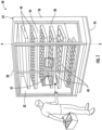
- the cabinet 20 includes a cabinet body or housing 22 having a bottom 24, a rear wall 26, a ceiling or roof 28, and side walls 30, 32.
- a refrigerated space 34 for displaying goods is located between the bottom 24, rear wall 26, ceiling 28, and side walls 30, 32.
- Arranged at a front side 36 of the cabinet body 22 is at least one door 40.
- the cabinet body 22 includes two doors 40, a left door and a right door, respectively.
- a cabinet body 22 having any number of doors 40 including a single door, three doors, or four or more doors for example, are within the scope of the invention.
- the doors 40 are illustrated as being at least partially transparent, embodiments where the doors 40 and therefore the contents of the refrigerated space are not visible at an exterior of the refrigerated display cabinet 20 are also contemplated herein.
- the at least one door 40 is movable between a closed position ( FIG. 1 ) in which the door 40 seals or at least partially seals the front side 36 of the cabinet body 22, and an open position, in which the front side 36 of the cabinet body is open and in fluid communication with the surrounding atmosphere.
- the doors 40 are configured to pivot or rotate about a respective axis X relative to the cabinet body 22 to transform between the closed position and the open position.
- the doors 40 can be operated manually, such as via one or more handles 42 for example, or alternatively or additionally, may be operated automatically, such as via a door motor (not shown), for example.
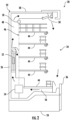
- the refrigerated space 34 typically includes a plurality of shelves 44 for supporting the goods displayed therein. As best shown in FIG. 2 , each shelf 44 may be supported at a rear end by a backwall panel 46.
- a backwall air channel 48 (also referred to herein as a "backwall channel") formed between the backwall panel 46 and the rear wall 26 of the cabinet body 22 and between the backwall panel 46 and the ceiling 28 of the cabinet body 22 defines a cooled air space.
- the backwall 46 includes a plurality of distribution holes or perforations 50 that allow cooled air to pass from the backwall air channel 48 into the refrigerated space 34.
- a heat exchanger 52 for cooling the air being provided to the shelves 44 may also be arranged within the backwall channel 48, such as between the backwall panel 46 and the rear wall 26 of the cabinet body 22.
- a fan 54 is positioned immediately upstream of the heat exchanger 52 at an aft end of a return cavity 56, formed between the bottom most shelf 44 and the bottom 24 of the cabinet body 22.
- the fan 54 drives air from the return cavity 56 through the heat exchanger 52, thereby causing all of the air to be cooled while flowing into the backwall channel 48. Accordingly, in combination, the return cavity 56 and the backwall channel 48 may be considered to form an air passage through the cabinet body.
- a redirection feature or a Discharge Air Grille (DAG) 58 may be arranged at the ceiling 28.
- DAG Discharge Air Grille
- the flow direction of the air is changed, such as by about 90 degrees, for example, such that the redirected cooled air is directed towards the lower shelves 44.
- FIGS 3A-5C illustrate various configurations of a modified refrigerated display cabinet having at least one of a cabinet tank with a reduced height and a backchannel with a reduced depth compared to existing refrigerated display cabinets.
- both the heat exchanger 152 and the fan 154 for moving a flow of air through the cabinet tank 156 and across the heat exchanger 152 are positioned within the cabinet tank 156.
- the fan 154 may be a cross flow fan.
- the fan 154 may be arranged at the corner of the refrigerated display cabinet 120 such that an inlet 160 of the fan 154 is arranged in fluid communication with the cabinet tank 156 and an outlet 162 of the fan 154 is arranged in fluid communication with the backwall channel 148.
- a cross-flow fan may be suitable in embodiments of the refrigerated display cabinet 120 where the internal height H (measured along a vertical axis) of the cabinet tank 156 is generally almost uniform ( FIG. 3A ) and embodiments where the internal height of the cabinet tank 156 has a stepped configuration (see FIG. 3B ).
- a width of the fan inlet 160 may be less than or equal to a width of the return cavity 156.
- a width of the fan inlet 160 is between about 25% and about 75% of the width of the cabinet tank 156.
- embodiments where the width is of the fan inlet 160 is less than 25% of the width of the cabinet tank 156, and embodiments where the width of the fan inlet 160 is greater than 75% of the cabinet tank 156 are also contemplated herein.
- the heat exchanger 152 is arranged within the cabinet tank 156, upstream from the cross-flow fan 154.
- the heat exchanger 152 within the cabinet tank 156 may be used in place of, or alternatively, in addition to a heat exchanger positioned within the backwall channel 148 as previously described.
- the heat exchanger may be a flat tube heat exchanger, also referred to herein as a "microchannel heat exchanger.”
- a flat tube heat exchanger includes an inlet manifold and an outlet manifold fluidly connected by a plurality of flat tubes.
- the flat tubes may be formed to include a plurality of channels, or internal passageways that are much smaller than the internal passageways of the tubes in a conventional round-tube plate-fin heat exchanger, such as the heat exchanger 52 of FIG. 2 .
- a conventional round-tube plate-fin heat exchanger such as the heat exchanger 52 of FIG. 2 .
- the heat exchanger 152 has another configuration, such as a round tube plate fin configuration for example, are also within the scope of the invention.
- a width of the heat exchanger 152 may be less than or equal to a width of the cabinet tank 156.
- a width of the heat exchanger 152 may be between about 50% and about 95% of the width of the cabinet tank 156.
- the width of the heat exchanger 152 may be the same or may be different than the width of the fan inlet 160.
- the width of the fan inlet 160 and the heat exchanger 152 are illustrated and described with respect to FIGS. 3A and 3B , it should be understood that the widths may similarly apply to the other embodiments of the modified refrigerated display cabinet disclosed herein.
- the heat exchanger 152 is arranged within the cabinet tank 156 in a forward mounting configuration.
- forward mounting configuration refers to embodiments where the forward or first end 164 of the heat exchanger 152 relative to the flow of air A through the cabinet tank 156 is arranged closest to the refrigerated space 134.
- the heat exchanger 152 may be located within the return cavity 156 in a backward mounting configuration.
- backward mounting configuration refers to embodiments where the back or second, downstream end 166 of the heat exchanger 152 relative to the flow of air through the cabinet tank 156 is arranged closest to the refrigerated space 134.
- the heat exchanger 152 is arranged at an angle relative to the horizontal air flow.
- an angle of the heat exchanger 152 in the forward mounting configuration is between about 20 degrees and about 80 degrees, such as between about 25 degrees and about 75 degrees, or between about 35 degrees and about 55 degrees.
- the angle of the heat exchanger 152 when in the backward mounting configuration is between about 100 degrees and about 160 degrees, such as between about 105 degrees and about 155 degrees, or between about 125 degrees and about 145 degrees.
- a heat exchanger 152 having a forward mounting configuration may be best suited for use in applications where the cabinet tank 156 has a uniform or almost uniform internal height and a heat exchanger 152 having a backward mounting configuration may be most suitable for use in a cabinet tank 156 having a stepped configuration.
- a heat exchanger 152 may be mounted in either configuration in a cabinet tank 156 having any configuration.
- FIGS. 4A and 4B another embodiment of a modified refrigerated display cabinet 220 having both a fan 254 and heat exchanger 252 arranged within the cabinet tank 256 is illustrated.
- the fan 254 is a mixed-flow fan 254.
- the heat exchanger 252 is arranged downstream from the mixed-flow fan 254.
- the heat exchanger 252 may be mounted such that a downstream end 266 of the heat exchanger 252 is generally aligned with the back channel 248.
- the heat exchanger 252 is arranged at a location further upstream within the cabinet tank 256 are also within the scope of the invention.
- the heat exchanger 252 may be a flat tube heat exchanger or another suitable type of heat exchanger.
- the mixed-flow fan 254 may be mounted at a non-perpendicular angle relative to horizontal flow of air A through the cabinet tank 256.
- the fan 254 is mounted in a forward mounting configuration where the first, upstream edge 268 of the fan 254 is arranged closest to the top of the cabinet tank 256. Accordingly, the second, downstream edge of the fan 254 may be positioned near the bottom 224 of the cabinet 220.
- the angle of the fan inlet face 254 relative to a horizontal air flow may be between about -20 degrees and about 70 degrees, such as between about -15 degrees and about 0 degrees, or between about 35 degrees and about 55 degrees, or between about 40 degrees and about 50 degrees.
- the fan 254 may be mounted in a backward mounting configuration, as shown in FIG. 4B .
- the back or downstream edge 270 of the fan 254 is arranged closest to the top of the cabinet tank.
- the first, upstream end 268 of the fan 254 may be arranged near the bottom 224 of the cabinet 220.
- An angle of a fan inlet face 254 in the backward mounting configuration relative to the horizontal air flow A may be between about 110 degrees and about 200 degrees, such as between about 120 degrees and about 160 degrees, or between about 130 degrees and about 150 degrees.
- the heat exchanger 252 is mounted in a forward mounting configuration regardless of how the fan 254 is oriented within the cabinet tank 256.
- the angle of the heat exchanger 252 relative to the horizontal air flow A when in the forward mounting configuration is between about 20 degrees and about 80 degrees, such as between about 25 degrees and about 75 degrees, or between about 35 degrees and about 55 degrees.
- the forward end 264 of the heat exchanger 252 may axially overlap with the downstream edge 270 of the mixed-flow fan 254.
- the heat exchanger 252 has a backward mounting configuration, regardless of whether the mixed-flow fan 254 is in a forward or backward mounting configuration are also within the scope of the invention.
- the fan 354 may be a mixed-flow fan.
- the fan 354 is positioned such that a portion of the casing of the fan 350 is arranged within the cabinet tank 356 and another portion of the casing is arranged within the backwall channel 348. Accordingly, as the fan impeller rotates, it will travel through both the cabinet tank 356 and the backwall channel 348.
- the fan 354 may be generally centered about the top of the cabinet tank 356 or with the bottom most shelf 344. However, embodiments where the fan 354 is offset therefrom are also contemplated herein. Further, the fan 354 may be positioned such that the fan axis is skewed relative to a horizontal air flow A. For example, the angle of the fan axis relative to the horizontal air flow A is between about -20 degrees and about 20 degrees, or between about -15 degrees and about 10 degrees.
- the heat exchanger 352 is illustrated as being positioned downstream from the fan 354 within the backwall channel 348.
- the heat exchanger 352 may be a flat tube heat exchanger or another suitable type of heat exchanger.
- the heat exchanger 352 is located within backwall channel 348 such that the first upstream end 364 of the heat exchanger 352 is arranged closest to the refrigerated space and the second, downstream end 366 is positioned near the rear wall 326 of the cabinet 320. Accordingly, in such a mounting configuration the angle of the heat exchanger 352 relative to vertical air flow is in between about 20 degrees and about 80 degrees, such as between about 25 degrees and about 75 degrees, or between about 35 degrees and about 55 degrees.
- the fan 354 is wholly positioned within the backwall channel 348, such as at a location vertically offset from the cabinet tank 356. As shown, the fan 354 may be mounted with the fan axis in a generally horizontal orientation. However, embodiments where the fan axis is arranged between about -20 degrees and about 20 degrees relative to horizontal, such as between about -10 degrees and 10 degrees for example, are also within the scope of the invention. In the illustrated non-limiting embodiment, the fan 354 is rotated 180 degrees relative to the fan 354 in FIG. 5A such that air is configured to flow through the fan 354 from the rear wall 326 towards the back wall panel 346.
- the heat exchanger 352 is arranged downstream from the outlet of the fan 354 such that the air output from the fan 354 will bounce off of the back wall panel 346 and flow toward the heat exchanger 352.
- the heat exchanger 352 may be arranged within the back channel 348 such that the forward or upstream end 364 of the heat exchanger 352 is located closest to the rear wall 326 and the back or downstream end 366 thereof is positioned adjacent to the back wall panel 346, closest to the refrigerated space 334.
- the angle of the heat exchanger 352 relative to vertical is between about 100 degrees and about 160 degrees, such as between about 105 degrees and about 155 degrees, or between about 125 degrees and 145 degrees for example.
- heat exchanger 352 is illustrated as being positioned downstream from the mixed-flow fan 354 within the backwall channel 348 in a cabinet 320 having a cabinet tank 356 of almost uniform height, it should be understood that such a configuration is suitable for use in a cabinet 320 having a cabinet tank 356 with any configuration, including a stepped configuration.
- the heat exchanger 352 is arranged upstream from the fan 354 relative to the flow of air A.
- the heat exchanger 352 may be disposed in the corner of the cabinet tank 356 at the interface between the cabinet tank 356 and the backwall channel 348.
- the heat exchanger 352 has a forward mounting configuration. In the forward mounting configuration, the angle of the heat exchanger 352 may be between about 20 degrees and about 80 degrees, such as between about 25 degrees and about 75 degrees, or between about 35 degrees and about 55 degrees.
- the heat exchanger 352 may be mounted in any suitable configuration, including a configuration where the first upstream end 364 thereof is positioned closest to the refrigerated space 334, or a configuration where the back end 366 of the heat exchanger 352 is positioned closest to the backwall panel 346 and the refrigerated space 334.
- a modified refrigerated display cabinet as described herein may have a reduced height of the cabinet tank of less than or equal to about 180mm, such as less than or equal to about 160mm, or even less than or equal to about 135mm.
- several benefits are achieved by integrating a mixed-flow fan and/or a cross flow fan into the air flow channel upstream or downstream from one or more heat exchangers including low noise, substantial higher flow/duty point, and substantial higher efficiency fan operation.
- better heat exchanger coil face air velocity distribution, and thus better air to refrigerant heat transfer is achieved, resulting in better air flow distribution inside the cabinet and thus more stable product temperatures, slowing down the deterioration of food quality and lower cabinet energy consumption.
Landscapes
- Physics & Mathematics (AREA)
- Thermal Sciences (AREA)
- Engineering & Computer Science (AREA)
- Mechanical Engineering (AREA)
- General Engineering & Computer Science (AREA)
- Freezers Or Refrigerated Showcases (AREA)
- Cold Air Circulating Systems And Constructional Details In Refrigerators (AREA)
Abstract
Description
- Embodiments of the present invention relate to refrigerated display cabinets, and more specifically to a heat exchanger configuration for refrigerated merchandisers.
- In practice, grocery stores and supermarkets use refrigerated merchandisers of different types, which may be open or with doors, for displaying and presenting fresh food and beverages to the customers, while maintaining a desired temperature of the products below a predefined threshold. In order to maintain the low temperature, cold air is circulated to the product display area of the cabinet by passing airflow over a heat exchanger surface of an evaporator. Refrigerant is pumped through the internal passages of the tubes which absorbs the heat from the air via fins and tube surfaces and the refrigerant changes from a liquid phase to a vapor phase in the process. As a result, the temperature of the air passing through the evaporator is lowered. One or more fans are typically included in the base of the refrigerated display cabinet and drive cold air through the heat exchanger, and deliver the cold air to the product display area of the merchandiser. Optimally designed refrigerated merchandisers are configured to maximize the display space without increasing the required footprint of the refrigerated merchandiser.
- According to a first aspect of the present invention, a refrigerated display cabinet includes a housing surrounding a plurality of shelves, a cabinet tank arranged beneath the plurality of shelves and a backwall channel positioned behind the plurality of shelves. The cabinet tank and the backwall channel cooperate to define an air passage. A micro-channel heat exchanger and a fan are arranged within the air passage, the fan being operable to move a flow of air through the heat exchanger. The fan is one of a cross-flow fan and a mixed-flow fan. The heat exchanger is arranged within the air passage at an angle between about 20 degrees and about 80 degrees or between about 100 degrees and about 160 degrees relative to the flow of air.
- The fan may be arranged within the cabinet tank.
- The heat exchanger may be arranged within the cabinet tank.
- The heat exchanger may be arranged in a forward mounting configuration.
- An angle of the heat exchanger may be between about 20 degrees and about 80 degrees.
- The heat exchanger may be arranged in a backward mounting configuration.
- An angle of the heat exchanger may be between about 100 degrees and about 160 degrees.
- The fan may be a mixed-flow fan arranged at an non-perpendicular angle relative to the flow of air through the air passage and the heat exchanger may be arranged downstream from the fan.
- The heat exchanger may axially overlap an edge of the fan.
- The heat exchanger may be arranged within the backwall channel.
- The fan may be at least partially arranged within the backwall channel.
- The fan may be a mixed-flow fan, the fan being mounted at an angle between - 20 degrees and about 20 degrees.
- The heat exchanger may be arranged downstream from the fan, the heat exchanger being arranged at an angle relative to a flow through the air passage.
- The heat exchanger may be arranged within the cabinet tank and the fan may be arranged within the backwall channel.
- A width of a fan inlet may be between about 25% and about 75% of the width of the cabinet tank.
- A width of the heat exchanger may be between about 50% and about 95% of the width of the cabinet tank.
- According to a second aspect of the present invention, a refrigerated display cabinet includes a housing surrounding a plurality of shelves, a cabinet tank arranged beneath the plurality of shelves and a backwall channel positioned behind the plurality of shelves. The cabinet tank and the backwall channel cooperate to define an air passage. A heat exchanger and a fan are arranged within the air passage, the fan being operable to move a flow of air through the heat exchanger. At least one of the fan and the heat exchanger is positioned within the cabinet tank, and a height of the cabinet tank is less than or equal to about 180mm. The heat exchanger may be a micro-channel heat exchanger.
- The fan may be a cross-flow fan.
- The fan may be a mixed-flow fan.
- The heat exchanger may be arranged at a non-perpendicular angle relative to a flow through the air passage.
- A detailed description of one or more embodiments are presented herein by way of exemplification and not limitation with reference to the Figures. The following descriptions should not be considered limiting in any way. With reference to the accompanying drawings, like elements are numbered alike:
-
FIG. 1 is a perspective view of a refrigerated display cabinet; -
FIG. 2 is a side view of a refrigerated display cabinet; -
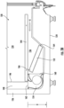
FIG. 3A is a side view of a portion of a modified refrigerated display cabinet; -
FIG. 3B is a side view of a portion of a modified refrigerated display cabinet; -
FIG. 4A is a side view of a portion of a modified refrigerated display cabinet; -
FIG. 4B is a side view of a portion of a modified refrigerated display cabinet; -
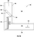
FIG. 5A is a side view of a portion of a modified refrigerated display cabinet; -
FIG. 5B is a side view of a portion of a modified refrigerated display cabinet; and -
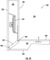
FIG. 5C is a side view of a portion of a modified refrigerated display cabinet. - With reference now to
FIGS. 1 and2 , a refrigerateddisplay cabinet 20 is illustrated. As shown, thecabinet 20 includes a cabinet body orhousing 22 having abottom 24, arear wall 26, a ceiling orroof 28, andside walls space 34 for displaying goods is located between thebottom 24,rear wall 26,ceiling 28, andside walls front side 36 of thecabinet body 22 is at least onedoor 40. In the illustrated example, thecabinet body 22 includes twodoors 40, a left door and a right door, respectively. However, it should be understood that acabinet body 22 having any number ofdoors 40 including a single door, three doors, or four or more doors for example, are within the scope of the invention. Further, although thedoors 40 are illustrated as being at least partially transparent, embodiments where thedoors 40 and therefore the contents of the refrigerated space are not visible at an exterior of the refrigerateddisplay cabinet 20 are also contemplated herein. - The at least one
door 40 is movable between a closed position (FIG. 1 ) in which thedoor 40 seals or at least partially seals thefront side 36 of thecabinet body 22, and an open position, in which thefront side 36 of the cabinet body is open and in fluid communication with the surrounding atmosphere. As shown, thedoors 40 are configured to pivot or rotate about a respective axis X relative to thecabinet body 22 to transform between the closed position and the open position. Thedoors 40 can be operated manually, such as via one ormore handles 42 for example, or alternatively or additionally, may be operated automatically, such as via a door motor (not shown), for example. - The refrigerated
space 34 typically includes a plurality ofshelves 44 for supporting the goods displayed therein. As best shown inFIG. 2 , eachshelf 44 may be supported at a rear end by abackwall panel 46. A backwall air channel 48 (also referred to herein as a "backwall channel") formed between thebackwall panel 46 and therear wall 26 of thecabinet body 22 and between thebackwall panel 46 and theceiling 28 of thecabinet body 22 defines a cooled air space. Thebackwall 46 includes a plurality of distribution holes orperforations 50 that allow cooled air to pass from thebackwall air channel 48 into the refrigeratedspace 34. - A
heat exchanger 52 for cooling the air being provided to theshelves 44 may also be arranged within thebackwall channel 48, such as between thebackwall panel 46 and therear wall 26 of thecabinet body 22. As shown inFIG. 2 , afan 54 is positioned immediately upstream of theheat exchanger 52 at an aft end of areturn cavity 56, formed between the bottommost shelf 44 and the bottom 24 of thecabinet body 22. Thefan 54 drives air from thereturn cavity 56 through theheat exchanger 52, thereby causing all of the air to be cooled while flowing into thebackwall channel 48. Accordingly, in combination, thereturn cavity 56 and thebackwall channel 48 may be considered to form an air passage through the cabinet body. While a portion of the cold air flows through the backwall holes 50, another portion of the cold air continues to flow upward to the portion of theair channel 48 arranged adjacent to theceiling 28. A redirection feature or a Discharge Air Grille (DAG) 58 may be arranged at theceiling 28. When the air flow contacts the redirection feature or theDAG 58, the flow direction of the air is changed, such as by about 90 degrees, for example, such that the redirected cooled air is directed towards thelower shelves 44. It should be understood that therefrigerated display cabinet 20 illustrated and described herein is intended as an example only, and that anyrefrigerated display cabinet 20 having one ormore doors 40 movable to access an internalrefrigerated space 34 is within the scope of the invention. -
FIGS 3A-5C , illustrate various configurations of a modified refrigerated display cabinet having at least one of a cabinet tank with a reduced height and a backchannel with a reduced depth compared to existing refrigerated display cabinets. With reference now toFIGS. 3A and3B , both theheat exchanger 152 and thefan 154 for moving a flow of air through thecabinet tank 156 and across theheat exchanger 152 are positioned within thecabinet tank 156. Thefan 154 may be a cross flow fan. Accordingly, thefan 154 may be arranged at the corner of therefrigerated display cabinet 120 such that aninlet 160 of thefan 154 is arranged in fluid communication with thecabinet tank 156 and anoutlet 162 of thefan 154 is arranged in fluid communication with thebackwall channel 148. As shown, a cross-flow fan may be suitable in embodiments of therefrigerated display cabinet 120 where the internal height H (measured along a vertical axis) of thecabinet tank 156 is generally almost uniform (FIG. 3A ) and embodiments where the internal height of thecabinet tank 156 has a stepped configuration (seeFIG. 3B ). - A width of the
fan inlet 160 may be less than or equal to a width of thereturn cavity 156. For example, a width of thefan inlet 160 is between about 25% and about 75% of the width of thecabinet tank 156. However, embodiments where the width is of thefan inlet 160 is less than 25% of the width of thecabinet tank 156, and embodiments where the width of thefan inlet 160 is greater than 75% of thecabinet tank 156 are also contemplated herein. - In the illustrated non-limiting embodiment, the
heat exchanger 152 is arranged within thecabinet tank 156, upstream from thecross-flow fan 154. Theheat exchanger 152 within thecabinet tank 156 may be used in place of, or alternatively, in addition to a heat exchanger positioned within thebackwall channel 148 as previously described. The heat exchanger may be a flat tube heat exchanger, also referred to herein as a "microchannel heat exchanger." A flat tube heat exchanger includes an inlet manifold and an outlet manifold fluidly connected by a plurality of flat tubes. The flat tubes may be formed to include a plurality of channels, or internal passageways that are much smaller than the internal passageways of the tubes in a conventional round-tube plate-fin heat exchanger, such as theheat exchanger 52 ofFIG. 2 . However, it should be understood that embodiments where theheat exchanger 152 has another configuration, such as a round tube plate fin configuration for example, are also within the scope of the invention. - A width of the
heat exchanger 152 may be less than or equal to a width of thecabinet tank 156. A width of theheat exchanger 152 may be between about 50% and about 95% of the width of thecabinet tank 156. However, embodiments where the width of theheat exchanger 152 is less than 50% of the width of thecabinet tank 156, and embodiments where the width of theheat exchanger 152 is greater than 95% of thecabinet tank 156 are also contemplated herein. Further, the width of theheat exchanger 152 may be the same or may be different than the width of thefan inlet 160. Although the width of thefan inlet 160 and theheat exchanger 152 are illustrated and described with respect toFIGS. 3A and3B , it should be understood that the widths may similarly apply to the other embodiments of the modified refrigerated display cabinet disclosed herein. - In some embodiments, such as shown in
FIG. 3A , theheat exchanger 152 is arranged within thecabinet tank 156 in a forward mounting configuration. As used herein, the phrase "forward mounting configuration" refers to embodiments where the forward orfirst end 164 of theheat exchanger 152 relative to the flow of air A through thecabinet tank 156 is arranged closest to therefrigerated space 134. Alternatively, theheat exchanger 152 may be located within thereturn cavity 156 in a backward mounting configuration. As used herein, the phrase "backward mounting configuration" refers to embodiments where the back or second,downstream end 166 of theheat exchanger 152 relative to the flow of air through thecabinet tank 156 is arranged closest to therefrigerated space 134. - In both the forward mounting configuration and the backward mounting configuration, the
heat exchanger 152 is arranged at an angle relative to the horizontal air flow. For example, an angle of theheat exchanger 152 in the forward mounting configuration is between about 20 degrees and about 80 degrees, such as between about 25 degrees and about 75 degrees, or between about 35 degrees and about 55 degrees. For example, the angle of theheat exchanger 152 when in the backward mounting configuration is between about 100 degrees and about 160 degrees, such as between about 105 degrees and about 155 degrees, or between about 125 degrees and about 145 degrees. - In embodiments where the
heat exchanger 152 is used in combination with across flow fan 154, aheat exchanger 152 having a forward mounting configuration may be best suited for use in applications where thecabinet tank 156 has a uniform or almost uniform internal height and aheat exchanger 152 having a backward mounting configuration may be most suitable for use in acabinet tank 156 having a stepped configuration. However, it should be understood that aheat exchanger 152 may be mounted in either configuration in acabinet tank 156 having any configuration. - With reference now to
FIGS. 4A and4B , another embodiment of a modifiedrefrigerated display cabinet 220 having both a fan 254 andheat exchanger 252 arranged within thecabinet tank 256 is illustrated. In the illustrated non-limiting embodiment, the fan 254 is a mixed-flow fan 254. In such embodiments where a mixed-flow fan 254 is arranged within thecabinet tank 256, theheat exchanger 252 is arranged downstream from the mixed-flow fan 254. Theheat exchanger 252 may be mounted such that adownstream end 266 of theheat exchanger 252 is generally aligned with theback channel 248. However, embodiments where theheat exchanger 252 is arranged at a location further upstream within thecabinet tank 256 are also within the scope of the invention. Theheat exchanger 252 may be a flat tube heat exchanger or another suitable type of heat exchanger. - As shown, the mixed-flow fan 254 may be mounted at a non-perpendicular angle relative to horizontal flow of air A through the
cabinet tank 256. In the embodiment shown inFIG. 4A , the fan 254 is mounted in a forward mounting configuration where the first,upstream edge 268 of the fan 254 is arranged closest to the top of thecabinet tank 256. Accordingly, the second, downstream edge of the fan 254 may be positioned near thebottom 224 of thecabinet 220. In the forward mounting configuration, the angle of the fan inlet face 254 relative to a horizontal air flow may be between about -20 degrees and about 70 degrees, such as between about -15 degrees and about 0 degrees, or between about 35 degrees and about 55 degrees, or between about 40 degrees and about 50 degrees. - Alternatively, the fan 254 may be mounted in a backward mounting configuration, as shown in
FIG. 4B . In the backward mounting configuration, the back ordownstream edge 270 of the fan 254 is arranged closest to the top of the cabinet tank. Accordingly, the first,upstream end 268 of the fan 254 may be arranged near thebottom 224 of thecabinet 220. An angle of a fan inlet face 254 in the backward mounting configuration relative to the horizontal air flow A may be between about 110 degrees and about 200 degrees, such as between about 120 degrees and about 160 degrees, or between about 130 degrees and about 150 degrees. - In the illustrated non-limiting embodiments, the
heat exchanger 252 is mounted in a forward mounting configuration regardless of how the fan 254 is oriented within thecabinet tank 256. The angle of theheat exchanger 252 relative to the horizontal air flow A when in the forward mounting configuration is between about 20 degrees and about 80 degrees, such as between about 25 degrees and about 75 degrees, or between about 35 degrees and about 55 degrees. In embodiments where both theheat exchanger 252 and the mixed-flow fan 254 have a forward mounting configuration, theforward end 264 of theheat exchanger 252 may axially overlap with thedownstream edge 270 of the mixed-flow fan 254. However, it should be understood that embodiments where theheat exchanger 252 has a backward mounting configuration, regardless of whether the mixed-flow fan 254 is in a forward or backward mounting configuration are also within the scope of the invention. - With reference now to
FIGS. 5A-5C , embodiments of a modifiedrefrigerated display cabinet 320 where at least one or both of theheat exchanger 352 and thefan 354 are arranged within theback channel 348 are illustrated. In each of the embodiments shown inFIGS. 5A-5C , thefan 354 may be a mixed-flow fan. In the non-limiting embodiment ofFIG. 5A , thefan 354 is positioned such that a portion of the casing of the fan 350 is arranged within thecabinet tank 356 and another portion of the casing is arranged within thebackwall channel 348. Accordingly, as the fan impeller rotates, it will travel through both thecabinet tank 356 and thebackwall channel 348. As shown, thefan 354 may be generally centered about the top of thecabinet tank 356 or with the bottommost shelf 344. However, embodiments where thefan 354 is offset therefrom are also contemplated herein. Further, thefan 354 may be positioned such that the fan axis is skewed relative to a horizontal air flow A. For example, the angle of the fan axis relative to the horizontal air flow A is between about -20 degrees and about 20 degrees, or between about -15 degrees and about 10 degrees. - With continued reference to
FIG. 5A , theheat exchanger 352 is illustrated as being positioned downstream from thefan 354 within thebackwall channel 348. As previously described, theheat exchanger 352 may be a flat tube heat exchanger or another suitable type of heat exchanger. In the illustrated non-limiting embodiment, theheat exchanger 352 is located withinbackwall channel 348 such that the firstupstream end 364 of theheat exchanger 352 is arranged closest to the refrigerated space and the second,downstream end 366 is positioned near therear wall 326 of thecabinet 320. Accordingly, in such a mounting configuration the angle of theheat exchanger 352 relative to vertical air flow is in between about 20 degrees and about 80 degrees, such as between about 25 degrees and about 75 degrees, or between about 35 degrees and about 55 degrees. - With reference now to the portion of a modified
refrigerated display cabinet 320 shown inFIGS. 5B and5C , in the illustrated non-limiting embodiments, thefan 354 is wholly positioned within thebackwall channel 348, such as at a location vertically offset from thecabinet tank 356. As shown, thefan 354 may be mounted with the fan axis in a generally horizontal orientation. However, embodiments where the fan axis is arranged between about -20 degrees and about 20 degrees relative to horizontal, such as between about -10 degrees and 10 degrees for example, are also within the scope of the invention. In the illustrated non-limiting embodiment, thefan 354 is rotated 180 degrees relative to thefan 354 inFIG. 5A such that air is configured to flow through thefan 354 from therear wall 326 towards theback wall panel 346. - With reference to
FIG. 5B , theheat exchanger 352 is arranged downstream from the outlet of thefan 354 such that the air output from thefan 354 will bounce off of theback wall panel 346 and flow toward theheat exchanger 352. Theheat exchanger 352 may be arranged within theback channel 348 such that the forward orupstream end 364 of theheat exchanger 352 is located closest to therear wall 326 and the back ordownstream end 366 thereof is positioned adjacent to theback wall panel 346, closest to therefrigerated space 334. The angle of theheat exchanger 352 relative to vertical is between about 100 degrees and about 160 degrees, such as between about 105 degrees and about 155 degrees, or between about 125 degrees and 145 degrees for example. Although theheat exchanger 352 is illustrated as being positioned downstream from the mixed-flow fan 354 within thebackwall channel 348 in acabinet 320 having acabinet tank 356 of almost uniform height, it should be understood that such a configuration is suitable for use in acabinet 320 having acabinet tank 356 with any configuration, including a stepped configuration. - In another embodiment, as shown in
FIG. 5C , theheat exchanger 352 is arranged upstream from thefan 354 relative to the flow of air A. As shown, theheat exchanger 352 may be disposed in the corner of thecabinet tank 356 at the interface between thecabinet tank 356 and thebackwall channel 348. To maximize the flow of the air provided to theheat exchanger 352, theheat exchanger 352 has a forward mounting configuration. In the forward mounting configuration, the angle of theheat exchanger 352 may be between about 20 degrees and about 80 degrees, such as between about 25 degrees and about 75 degrees, or between about 35 degrees and about 55 degrees. However, it should be understood that embodiments where theheat exchanger 352 is arranged at another location upstream from thefan 354, such as at a location at least partially within thebackwall channel 348 for example, is also contemplated herein. In such embodiments, theheat exchanger 352 may be mounted in any suitable configuration, including a configuration where the firstupstream end 364 thereof is positioned closest to therefrigerated space 334, or a configuration where theback end 366 of theheat exchanger 352 is positioned closest to thebackwall panel 346 and therefrigerated space 334. - The fan and heat exchanger arrangements as described herein are uniquely selected to minimize the in-situ aerodynamic duty losses and maximize the air management system efficiency. A modified refrigerated display cabinet as described herein may have a reduced height of the cabinet tank of less than or equal to about 180mm, such as less than or equal to about 160mm, or even less than or equal to about 135mm. Further, several benefits are achieved by integrating a mixed-flow fan and/or a cross flow fan into the air flow channel upstream or downstream from one or more heat exchangers including low noise, substantial higher flow/duty point, and substantial higher efficiency fan operation. In addition, better heat exchanger coil face air velocity distribution, and thus better air to refrigerant heat transfer is achieved, resulting in better air flow distribution inside the cabinet and thus more stable product temperatures, slowing down the deterioration of food quality and lower cabinet energy consumption.
- The term "about" is intended to include the degree of error associated with measurement of the particular quantity based upon the equipment available at the time of filing the application.
- The terminology used herein is for the purpose of describing particular embodiments only and is not intended to be limiting of the present invention. As used herein, the singular forms "a", "an" and "the" are intended to include the plural forms as well, unless the context clearly indicates otherwise. It will be further understood that the terms "comprises" and/or "comprising," when used in this specification, specify the presence of stated features, integers, steps, operations, elements, and/or components, but do not preclude the presence or addition of one or more other features, integers, steps, operations, element components, and/or groups thereof.
- While the present invention has been described with reference to an exemplary embodiment or embodiments, it will be understood by those skilled in the art that various changes may be made and equivalents may be substituted for elements thereof without departing from the scope of the present invention, as defined in the appended claims. In addition, many modifications may be made to adapt a particular situation or material to the teachings of the present invention without departing from the scope thereof. Therefore, it is intended that the present invention not be limited to the particular embodiment disclosed as the best mode contemplated for carrying out this present invention, but that the present invention will include all embodiments falling within the scope of the claims.
Claims (15)
- A refrigerated display cabinet (20; 120; 220; 320) comprising:a housing (22) surrounding a plurality of shelves (44);a cabinet tank (56; 156; 256; 356) arranged beneath the plurality of shelves (44);a backwall channel (48; 148; 248; 348) positioned behind the plurality of shelves (44), wherein the cabinet tank (56; 156; 256; 356) and the backwall channel (48; 148; 248; 348) cooperate to define an air passage;a micro-channel heat exchanger (152; 252; 352) arranged within the air passage; anda fan (54; 154; 254; 354) disposed within the air passage, the fan (54; 154; 254; 354) being operable to move a flow of air through the heat exchanger (152; 252; 352), wherein the fan (54; 154; 254; 354) is one of a cross-flow fan (154) and a mixed-flow fan (254; 354);wherein the heat exchanger (152; 252; 352) is arranged within the air passage at an angle between about 20 degrees and about 80 degrees or between about 100 degrees and about 160 degrees relative to the flow of air.
- The refrigerated display cabinet (20; 120; 220) of claim 1, wherein the fan (54; 154; 254) is arranged within the cabinet tank (56; 156; 256).
- The refrigerated display cabinet (20; 120; 220) of claim 1 or 2, wherein the heat exchanger (152; 252) is arranged within the cabinet tank (56; 156; 256).
- The refrigerated display cabinet (20; 120; 220; 320) of any preceding claim, wherein the heat exchanger (152; 252; 352) is arranged in a forward mounting configuration; and optionally wherein the angle of the heat exchanger (152; 252; 352) is between about 20 degrees and about 80 degrees.
- The refrigerated display cabinet (20; 120; 220; 320) of any of claims 1 to 3, wherein the heat exchanger (152; 252; 352) is arranged in a backward mounting configuration; and optionally wherein an angle of the heat exchanger (152; 252; 352) is between about 100 degrees and about 160 degrees.
- The refrigerated display cabinet (220; 320) of claim 3, wherein the fan (254; 354) is a mixed-flow fan (254; 354) arranged at a non-perpendicular angle relative to the flow of air through the air passage and the heat exchanger (252; 352) is arranged downstream from the fan; and optionally wherein the heat exchanger (252) axially overlaps an edge of the fan (254).
- The refrigerated display cabinet (20; 320) of claim 1, wherein the heat exchanger (352) is arranged within the backwall channel (48; 348).
- The refrigerated display cabinet (20; 320) of claim 7, wherein the fan (54; 354) is at least partially arranged within the backwall channel (48; 348).
- The refrigerated display cabinet (220; 320) of claim 8, wherein the fan (254; 354) is a mixed-flow fan (254; 354), the fan (254; 354) being mounted at an angle between -20 degrees and about 20 degrees.
- The refrigerated display cabinet (20; 220; 320) of claim 8 or 9, wherein the heat exchanger (252; 352) is arranged downstream from the fan (254; 354), the heat exchanger (252; 352) being arranged at an angle relative to a flow through the air passage.
- The refrigerated display cabinet (320) of claim 1, wherein the heat exchanger (352) is arranged within the cabinet tank (356) and the fan (354) is arranged within the backwall channel (348).
- The refrigerated display cabinet (20; 120) of any preceding claim, wherein a width of a fan inlet (160) is between about 25% and about 75% of the width of the cabinet tank (156); and/or wherein a width of the heat exchanger (152) is between about 50% and about 95% of the width of the cabinet tank (156).
- A refrigerated display cabinet (20; 120; 220; 320) comprising:a housing (22) surrounding a plurality of shelves (44);a cabinet tank (56; 156; 256; 356) arranged beneath the plurality of shelves (44);a backwall channel (48; 148; 248; 348) positioned behind the plurality of shelves (44), wherein the cabinet tank (56; 156; 256; 356) and the backwall channel (48; 148; 248; 348) cooperate to defined an air passage;a heat exchanger (152; 252; 352) arranged within the air passage; anda fan disposed (54; 154; 254; 354) within the air passage, the fan being operable to move a flow of air through the heat exchanger (152; 252; 352);wherein at least one of the fan (54; 154; 254; 354) and the heat exchanger (152; 252; 352) is positioned within the cabinet tank (56; 156; 256; 356), and a height of the cabinet tank (56; 156; 256; 356) is less than or equal to about 180mm.
- The refrigerated display cabinet (20; 120; 220; 320) of claim 13, wherein the fan (54; 154; 254; 354) is a cross-flow fan (154) or a mixed-flow fan (254; 354).
- The refrigerated display cabinet (20; 120; 220; 320) of claim 13 or 14, wherein the heat exchanger (152; 252; 352) is arranged at a non-perpendicular angle relative to a flow through the air passage.
Applications Claiming Priority (1)
| Application Number | Priority Date | Filing Date | Title |
|---|---|---|---|
| US202263313524P | 2022-02-24 | 2022-02-24 |
Publications (1)
| Publication Number | Publication Date |
|---|---|
| EP4268678A1 true EP4268678A1 (en) | 2023-11-01 |
Family
ID=85380792
Family Applications (1)
| Application Number | Title | Priority Date | Filing Date |
|---|---|---|---|
| EP23158360.0A Withdrawn EP4268678A1 (en) | 2022-02-24 | 2023-02-23 | Refrigerated display cabinet |
Country Status (3)
| Country | Link |
|---|---|
| US (1) | US20230263317A1 (en) |
| EP (1) | EP4268678A1 (en) |
| CN (1) | CN116636718A (en) |
Families Citing this family (1)
| Publication number | Priority date | Publication date | Assignee | Title |
|---|---|---|---|---|
| EP4321058A1 (en) * | 2022-08-09 | 2024-02-14 | Carrier Corporation | Method of manufacturing a display cabinet |
Citations (5)
| Publication number | Priority date | Publication date | Assignee | Title |
|---|---|---|---|---|
| US20050076662A1 (en) * | 2003-10-10 | 2005-04-14 | Hussmann Corporation | Evaporator for refrigerated merchandisers |
| CN1608191A (en) * | 2001-12-27 | 2005-04-20 | Gac株式会社 | Storage device |
| US20100064712A1 (en) * | 2006-07-28 | 2010-03-18 | Carrier Corporation | Refrigerated display merchandiser with microchannel evaporator oriented to reliably remove condensate |
| US20190234419A1 (en) * | 2018-01-31 | 2019-08-01 | Carrier Corporation | Axial fan with tip fences |
| US20200352356A1 (en) * | 2019-05-07 | 2020-11-12 | Carrier Corporation | Refrigerated display cabinet utilizing a radial cross flow fan |
Family Cites Families (1)
| Publication number | Priority date | Publication date | Assignee | Title |
|---|---|---|---|---|
| US8739855B2 (en) * | 2012-02-17 | 2014-06-03 | Hussmann Corporation | Microchannel heat exchanger |
-
2023
- 2023-02-22 CN CN202310149867.2A patent/CN116636718A/en active Pending
- 2023-02-22 US US18/172,422 patent/US20230263317A1/en not_active Abandoned
- 2023-02-23 EP EP23158360.0A patent/EP4268678A1/en not_active Withdrawn
Patent Citations (5)
| Publication number | Priority date | Publication date | Assignee | Title |
|---|---|---|---|---|
| CN1608191A (en) * | 2001-12-27 | 2005-04-20 | Gac株式会社 | Storage device |
| US20050076662A1 (en) * | 2003-10-10 | 2005-04-14 | Hussmann Corporation | Evaporator for refrigerated merchandisers |
| US20100064712A1 (en) * | 2006-07-28 | 2010-03-18 | Carrier Corporation | Refrigerated display merchandiser with microchannel evaporator oriented to reliably remove condensate |
| US20190234419A1 (en) * | 2018-01-31 | 2019-08-01 | Carrier Corporation | Axial fan with tip fences |
| US20200352356A1 (en) * | 2019-05-07 | 2020-11-12 | Carrier Corporation | Refrigerated display cabinet utilizing a radial cross flow fan |
Also Published As
| Publication number | Publication date |
|---|---|
| US20230263317A1 (en) | 2023-08-24 |
| CN116636718A (en) | 2023-08-25 |
Similar Documents
| Publication | Publication Date | Title |
|---|---|---|
| US11737583B2 (en) | Air curtain blanking plate | |
| US11559147B2 (en) | Refrigerated display cabinet utilizing a radial cross flow fan | |
| RU2650401C2 (en) | Refrigerated display appliances | |
| US11304543B2 (en) | System comprising a display unit for storing and displaying food products, and multiple shelves, and method for storing and displaying refrigerated food products in a display unit | |
| US3324783A (en) | Air directing grid construction | |
| US20230263317A1 (en) | Refrigereated display cabinet with mixed or cross flow fan | |
| US12096867B2 (en) | Merchandiser | |
| CN101557738A (en) | Refrigerated display merchandiser with microchannel evaporator oriented to reliably remove condensate | |
| JP4562452B2 (en) | Flat open showcase | |
| EP3735868B1 (en) | Refrigerant display cabinet including microchannel heat exchangers and cooling method | |
| EP3736515B1 (en) | Refrigerated display cabinet including microchannel heat exchangers | |
| US6792772B1 (en) | Refrigerated cooler | |
| US20240016314A1 (en) | Merchandiser | |
| CN112797693A (en) | Refrigerated display case with air flow guide | |
| EP4155623A1 (en) | Cabinet for refrigeration and storage of food products | |
| GB2627470A (en) | An extraction apparatus and method | |
| NL2023984B1 (en) | System comprising a display unit for storing and displaying food products, and multiple shelves, and method for storing and displaying refrigerated food products in a display unit | |
| CN118806072A (en) | Refrigerated display cabinets | |
| JPH11264643A (en) | Refrigerated showcase | |
| KR20140099678A (en) | Show case | |
| JPH06307755A (en) | Low temperature display case |
Legal Events
| Date | Code | Title | Description |
|---|---|---|---|
| PUAI | Public reference made under article 153(3) epc to a published international application that has entered the european phase |
Free format text: ORIGINAL CODE: 0009012 |
|
| STAA | Information on the status of an ep patent application or granted ep patent |
Free format text: STATUS: THE APPLICATION HAS BEEN PUBLISHED |
|
| AK | Designated contracting states |
Kind code of ref document: A1 Designated state(s): AL AT BE BG CH CY CZ DE DK EE ES FI FR GB GR HR HU IE IS IT LI LT LU LV MC ME MK MT NL NO PL PT RO RS SE SI SK SM TR |
|
| STAA | Information on the status of an ep patent application or granted ep patent |
Free format text: STATUS: REQUEST FOR EXAMINATION WAS MADE |
|
| 17P | Request for examination filed |
Effective date: 20240501 |
|
| RBV | Designated contracting states (corrected) |
Designated state(s): AL AT BE BG CH CY CZ DE DK EE ES FI FR GB GR HR HU IE IS IT LI LT LU LV MC ME MK MT NL NO PL PT RO RS SE SI SK SM TR |
|
| STAA | Information on the status of an ep patent application or granted ep patent |
Free format text: STATUS: EXAMINATION IS IN PROGRESS |
|
| 17Q | First examination report despatched |
Effective date: 20250218 |
|
| STAA | Information on the status of an ep patent application or granted ep patent |
Free format text: STATUS: THE APPLICATION IS DEEMED TO BE WITHDRAWN |
|
| 18D | Application deemed to be withdrawn |
Effective date: 20250819 |