EP4268569A1 - Working machine and working device - Google Patents
Working machine and working device Download PDFInfo
- Publication number
- EP4268569A1 EP4268569A1 EP23169635.2A EP23169635A EP4268569A1 EP 4268569 A1 EP4268569 A1 EP 4268569A1 EP 23169635 A EP23169635 A EP 23169635A EP 4268569 A1 EP4268569 A1 EP 4268569A1
- Authority
- EP
- European Patent Office
- Prior art keywords
- controller
- imaging data
- swath
- grass
- rake
- Prior art date
- Legal status (The legal status is an assumption and is not a legal conclusion. Google has not performed a legal analysis and makes no representation as to the accuracy of the status listed.)
- Pending
Links
Images












Classifications
-
- A—HUMAN NECESSITIES
- A01—AGRICULTURE; FORESTRY; ANIMAL HUSBANDRY; HUNTING; TRAPPING; FISHING
- A01D—HARVESTING; MOWING
- A01D78/00—Haymakers with tines moving with respect to the machine
- A01D78/005—Turners; Tedders
- A01D78/006—Rotating turners
- A01D78/007—Control mechanisms therefor
-
- A—HUMAN NECESSITIES
- A01—AGRICULTURE; FORESTRY; ANIMAL HUSBANDRY; HUNTING; TRAPPING; FISHING
- A01D—HARVESTING; MOWING
- A01D78/00—Haymakers with tines moving with respect to the machine
- A01D78/08—Haymakers with tines moving with respect to the machine with tine-carrying rotary heads or wheels
- A01D78/10—Haymakers with tines moving with respect to the machine with tine-carrying rotary heads or wheels the tines rotating about a substantially vertical axis
-
- A—HUMAN NECESSITIES
- A01—AGRICULTURE; FORESTRY; ANIMAL HUSBANDRY; HUNTING; TRAPPING; FISHING
- A01D—HARVESTING; MOWING
- A01D78/00—Haymakers with tines moving with respect to the machine
- A01D78/08—Haymakers with tines moving with respect to the machine with tine-carrying rotary heads or wheels
- A01D78/10—Haymakers with tines moving with respect to the machine with tine-carrying rotary heads or wheels the tines rotating about a substantially vertical axis
- A01D78/1078—Having only one row of rotors arranged on the same horizontal line perpendicular to the advance direction of the machine
-
- G—PHYSICS
- G07—CHECKING-DEVICES
- G07C—TIME OR ATTENDANCE REGISTERS; REGISTERING OR INDICATING THE WORKING OF MACHINES; GENERATING RANDOM NUMBERS; VOTING OR LOTTERY APPARATUS; ARRANGEMENTS, SYSTEMS OR APPARATUS FOR CHECKING NOT PROVIDED FOR ELSEWHERE
- G07C5/00—Registering or indicating the working of vehicles
- G07C5/02—Registering or indicating driving, working, idle, or waiting time only
-
- A—HUMAN NECESSITIES
- A01—AGRICULTURE; FORESTRY; ANIMAL HUSBANDRY; HUNTING; TRAPPING; FISHING
- A01D—HARVESTING; MOWING
- A01D78/00—Haymakers with tines moving with respect to the machine
- A01D78/08—Haymakers with tines moving with respect to the machine with tine-carrying rotary heads or wheels
- A01D78/10—Haymakers with tines moving with respect to the machine with tine-carrying rotary heads or wheels the tines rotating about a substantially vertical axis
- A01D78/1071—Having only one rotor
-
- A—HUMAN NECESSITIES
- A01—AGRICULTURE; FORESTRY; ANIMAL HUSBANDRY; HUNTING; TRAPPING; FISHING
- A01D—HARVESTING; MOWING
- A01D78/00—Haymakers with tines moving with respect to the machine
- A01D78/08—Haymakers with tines moving with respect to the machine with tine-carrying rotary heads or wheels
- A01D78/10—Haymakers with tines moving with respect to the machine with tine-carrying rotary heads or wheels the tines rotating about a substantially vertical axis
- A01D78/1085—Having two rows of rotors on two different horizontal lines perpendicular to the advance direction of the machine
Definitions
- the present invention relates to a working machine, such as a raking machine that performs raking, and a working device.
- Patent Literature 1 discloses a raking machine including a tractor and a rake coupled to a rear portion of the tractor. Cut grass in an agricultural field is raked to form swaths by operating the rake towed by the tractor. Patent Literature 1 also discloses a process where swaths formed as a result of raking are introduced into a roll baler or the like and the roll baler bales the swaths into a certain shape and discharges roll bales onto an agricultural field.
- the present invention has been made to address this problem in the example of the related art and aims to easily make shapes of swaths and the like uniform.
- a working machine includes a traveling vehicle, a working device to rake grass in an agricultural field and form a swath, the working device being coupled to the traveling vehicle, a sensor to obtain a state of the grass or the swath in the agricultural field, and a controller to, when the working device performs raking, change one or more pieces of setting information regarding the working device based on the state obtained by the sensor.
- the sensor may include at least one imager to obtain imaging data by capturing an image of the state of the grass or the swath in the agricultural field.
- the controller may be configured or programmed to change the one or more pieces of setting information regarding the working device based on the imaging data obtained by the at least one imager.
- the at least one imager may be a first imager to obtain imaging data by capturing an image of the state of the swath formed by the working device.
- the controller may be configured or programmed to change the one or more pieces of setting information regarding the working device based on the imaging data of a work product obtained by the first imager and indicating the state of the formed swath.
- the at least one imager may be a second imager to obtain imaging data by capturing an image of the state of the grass in the agricultural field.
- the controller may be configured or programmed to change the one or more pieces of setting information regarding the working device based on the imaging data which is pre-work imaging data obtained by the second imager before raking is performed and indicating the state of the grass in the agricultural field.
- the at least one imager may include a first imager to obtain imaging data by capturing an image of the state of the swath formed by the working device and a second imager to obtain imaging data by capturing an image of the state of the grass in the agricultural field.
- the controller may be configured or programmed to change the one or more pieces of setting information regarding the working device based on the imaging data of a work product obtained by the first imager and indicating the state of the formed swath, and the imaging data which is pre-work imaging data obtained by the second imager before raking is performed and indicating the state of the grass in the agricultural field.
- the working device may include a rake unit including a body, a rotor rotatably supported by the body, tine arms coupled to the rotor and radially extending from the rotor, one or more tines coupled to each of the tine arms and extending downward, and a plate-like member to form the swath.
- the controller may be configured or programmed to change one of the one or more pieces of setting information regarding the working device that indicates a clearance between the plate-like member and the body based on the imaging data of the work product.
- the working device may include a rake unit including a body, a rotor rotatably supported by the body, tine arms coupled to the rotor and radially extending from the rotor, one or more tines coupled to each of the tine arms and extending downward, and a plate-like member to form the swath.
- the controller may be configured or programmed to change one of the one or more pieces of setting information regarding the working device that indicates a clearance between the plate-like member and the body based on the pre-work imaging data.
- the working device may include a rake unit including a body, a rotor rotatably supported by the body, tine arms coupled to the rotor and radially extending from the rotor, and one or more tines coupled to each of the tine arms and extending downward.
- the controller may be configured or programmed to change one of the one or more pieces of setting information regarding the working device that indicates a distance between a lower end of the rake unit and the agricultural field based on the pre-work imaging data.
- the working device may include a rake unit including a body, a rotor rotatably supported by the body, tine arms coupled to the rotor and radially extending from the rotor, and one or more tines coupled to each of the tine arms and extending downward.
- the controller may be configured or programmed to change one of the one or more pieces of setting information regarding the working device that indicates travel speed of the traveling vehicle based on the pre-work imaging data.
- the traveling vehicle may include a prime mover and a power take-off shaft driven by power from the prime mover.
- the working device may include a rake unit including a body, a rotor which is rotatably supported by the body and to which power from the power take-off shaft is transmitted, tine arms coupled to the rotor and radially extending from the rotor, and one or more tines coupled to each of the tine arms and extending downward.
- the controller may be configured or programmed to change one of the one or more pieces of setting information regarding the working device that indicates a rotation speed of the power take-off shaft based on the pre-work imaging data.
- the traveling vehicle may include a prime mover and a power take-off shaft driven by power from the prime mover.
- the working device may include a rake unit including a body, a rotor which is rotatably supported by the body and to which power from the power take-off shaft is transmitted, tine arms coupled to the rotor and radially extending from the rotor, and one or more tines coupled to each of the tine arms and extending downward.
- the controller may be configured or programmed to change one of the one or more pieces of setting information regarding the working device that indicates a rotation speed of the power take-off shaft based on the imaging data of the work product.
- the working machine may further include a positioning device to obtain measured position information.
- the controller may be configured or programmed to obtain one or more pieces of imaging data in a tedding step preceding a raking step, the one or more pieces of imaging data being associated with one or more pieces of positional information indicating one or more positions at which the one or more pieces of imaging data have been obtained, and change the one or more pieces of setting information regarding the working device based on one of the obtained one or more pieces of imaging data that corresponds to one of the one or more pieces of positional information that matches the measured position information obtained by the positioning device.
- the working machine may further include a positioning device to obtain measured position information, a memory, and a communicator.
- the controller may be configured or programmed to generate work product record data in which the measured position information obtained by the positioning device and the imaging data of the work product are associated with each other, cause the memory to store the work product record data, and cause the communicator to transmit the work product record data stored in the memory to an external information processor.
- a working device includes a rake unit to rake grass in an agricultural field and form a swath, the rake unit being couplable to a traveling vehicle.
- the rake unit may be operable to, based on a state of the grass or the swath in the agricultural field, change a condition in which the swath is formed.
- the rake unit may be operable to, based on imaging data obtained by capturing an image of the state of the grass or the swath in the agricultural field, change the condition in which the swath is formed.
- the rake unit may be operable to, based on imaging data of a work product indicating the state of the swath formed by the rake unit, a condition in which a next swath is formed.
- the rake unit may be operable to, based on pre-work imaging data indicating the state of the grass in the agricultural field before raking is performed by the rake unit, change a condition in which a next swath is formed.
- the rake unit may include a body, a rotor rotatably supported by the body, tine arms coupled to the rotor and radially extending from the rotor, one or more tines coupled to each of the tine arms and extending downward, and a plate-like member to form the swath.
- the plate-like member may be operable to change a clearance between the plate-like member and the body based on the imaging data or the pre-work imaging data.
- shapes of swaths and the like can be easily made uniform.
- FIG. 1 is a diagram illustrating the entirety of a grass management system.
- the grass management system is a system that manages matters relating to grass planted in an agricultural field.
- FIG. 1 illustrates working machines of four types.
- the working machines of four types are a mowing machine 1A, a tedding machine 1B, a raking machine 1C, and a baling machine 1D.
- the mowing machine 1A mows grass in an agricultural field and discharges cut grass to the outside.
- the tedding machine 1B teds the grass (cut grass) in the agricultural field.
- the raking machine 1C forms swaths by raking the grass tedded in the agricultural field.
- the baling machine 1D collects the grass in the form of swaths and bales the collected grass into a certain shape, namely, for example, a cylindrical shape or a cuboid shape.
- the mowing machine 1A includes a traveling vehicle 2A and a mower 3A coupled to the traveling vehicle 2A.
- the tedding machine 1B includes a traveling vehicle 2B and a tedder 3B coupled to the traveling vehicle 2B.
- the raking machine 1C includes a traveling vehicle 2C and a rake 3C coupled to the traveling vehicle 2C.
- the baling machine 1D includes a traveling vehicle 2D and a baler 3D coupled to the traveling vehicle 2D.
- the traveling vehicles 2A, 2B, 2C, and 2D are tractors which can travel. First, the traveling vehicles 2A, 2B, 2C, and 2D will be described.
- the traveling vehicles (tractors) 2A, 2B, 2C, and 2D each include a vehicle body 10, a prime mover 11, and a transmission 12.
- the vehicle body 10 is provided with a traveling device 13.
- the traveling device 13 includes front wheels and rear wheels.
- the traveling device 13 may be a crawler device.
- the prime mover 11 is a diesel engine, an electric motor, or the like and is a diesel engine in this embodiment.
- the transmission 12 can change propelling force of the traveling device 13 and switch forward traveling and backward traveling of the traveling device 13.
- a coupler 8 including a three-point linkage is provided in a rear portion of the vehicle body 10.
- a working device e.g., an implement
- the working device is, for example, the mower 3A, the tedder 3B, the rake 3C, or the baler 3D.
- the vehicle body 10 can tow the working device.
- the traveling vehicles 2A, 2B, 2C, and 2D each include a PTO shaft driven by power from the prime mover 11 or the like and can transmit power of the PTO shaft to the working device.
- the traveling vehicles 2A, 2B, 2C, and 2D each include a cabin 14 including an operator's seat therein.
- the traveling vehicles 2A, 2B, 2C, and 2D each include a controller 15.
- the controller 15 controls a traveling system and a working system of each of the traveling vehicles 2A, 2B, 2C, and 2D on the basis of operation signals at a time when operation actuators (an operation lever, an operation switch, an operation volume, etc.) provided around the operator's seat are used, detection signals of various sensors mounted on the vehicle body 10, and the like.
- the controller 15 raises or lowers the working device on the basis of use of the operation actuators (operation signals) and controls diesel engine speed on the basis of an acceleration pedal sensor.
- the controller 15 may be any controller that controls the working system and the traveling system of each of the traveling vehicle 2A, 2B, 2C, and 2D and employ any control method.
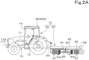
- the rake 3C includes a coupling frame 42 coupled to the coupler 8 of the traveling vehicle 2C and rake units 43 coupled to the coupling frame 42.
- FIGS. 2A and 2B illustrate an example where two rake units 43 are coupled to the coupling frame 42.
- the rake units 43 each include a body 44 coupled to the coupling frame 42, a rotor 45 rotatably supported by the body 44, arms (tine arms) 46 coupled to the rotor 45, and one or more tines 47 coupled to each of the arms 46.
- the intervals between the tines 47 of the rake 3C are shorter than those between forks of the tedder 3B.
- the tines 47 are, for example, bifurcated members.
- Power from a PTO shaft AX is transmitted to each of the rotors 45 via a driving shaft 28C supported by the coupling frame 42, thus rotating the rotors 45.
- the rotation of the rotors 45 causes the arms 46 to rotate, and the tines 47 rake grass. That is, the rotation of the rotors 45 causes the tines 47 to rotate, and the tines 47 rake grass.
- the configuration of the rake 3C is not limited to the above, provided that the rake 3C rakes grass.
- the number of rake units 43 may be one, or three or more.
- the rake units 43 may be of a rotary type in which a rotor to which tines 47 are attached rotates about a vertical axis, a belt/chain type in which tines 47 are attached to a belt or a chain that rotates, or any other type.
- the grass management system includes at least one position detector 60 capable of detecting the position of a working machine.
- the at least one position detector 60 includes a position detector 60A that detects the position of the mowing machine 1A.
- the at least one position detectors 60 includes a position detector 60B that detects the position of the tedding machine 1B.
- the at least one position detectors 60 includes a position detector 60C that detects the position of the raking machine 1C.
- the at least one position detectors 60 includes a position detector 60D that detects the position of the baling machine 1D.
- the position detectors 60A, 60B, 60C, and 60D will be described.
- the position detector 60A is mounted on a roof of the cabin 14 of the traveling vehicle 2A.
- the position detector 60B is mounted on a roof of the cabin 14 of the traveling vehicle 2B.
- the position detector 60C is mounted on a roof of the cabin 14 of the traveling vehicle 2C.
- the position detector 60D is mounted on a roof of the cabin 14 of the traveling vehicle 2D. That is, the position detectors 60A, 60B, 60C, and 60D are each mounted on the corresponding traveling vehicle.
- a position on the tractor (traveling vehicle) at which each of the position detectors 60A, 60B, 60C, and 60D is mounted is not limited, and may be mounted at another position.
- the position detectors 60A, 60B, 60C, and 60D detect positions (measured position information including latitude and longitude) thereof using a satellite positioning system. That is, the position detectors 60A, 60B, 60C, and 60D are capable of receiving signals (positions of positioning satellites, transmission times, correction information, etc.) transmitted from the positioning satellites and detecting the positions (e.g., latitude and longitude) thereof on the basis of the received signals.
- the position detectors 60A, 60B, 60C, and 60D may detect not only the positions based on latitude and longitude but also information in a vertical direction (height direction), that is, height information.
- a memory (first memory) 16A of the traveling vehicle 2A stores the position(s) during the mowing.
- a memory 16B of the traveling vehicle 2B stores the position(s) during the tedding.
- a memory 16C of the traveling vehicle 2C stores the position(s) during the raking.
- a memory (second memory) 16D of the traveling vehicle 2D stores the position(s) during the baling.
- the grass management system includes a first physical quantity detector 81.
- the first physical quantity detector 81 detects physical quantity(quantities) relating to grass such as component(s) of grass (moisture content and/or protein).
- the first physical quantity detector 81 is provided in or on the mowing machine 1A.
- the first physical quantity detector 81 obtains at least moisture value(s) (first moisture value(s)) of grass at the time of mowing performed by the mowing machine 1A.
- the first physical quantity detector 81 is provided in or on the mower 3A and obtains the first moisture value(s) of grass when the grass is mowed.
- the first physical quantity detector 81 is a spectrometer, for example, and analyzes the moisture in grass by emitting light having a certain frequency onto the grass and receiving light reflected from the grass.
- the first physical quantity detector 81 is connected to the controller 15 or the memory 16A of the traveling vehicle 2A.
- the controller 15 stores the first moisture value(s) obtained by the first physical quantity detector 81 and position(s) at which grass was mowed (hereinafter "mowing positions", latitude and longitude) detected by the position detector 60A in the memory 16A as map data regarding the first moisture values in which the first moisture values and the mowing positions are associated with each other.
- the traveling vehicle 2A includes a communicator 82A.
- the communicator 82A is connected to at least the memory 16A and outputs the map data regarding the first moisture values (the mowing positions and the first moisture values) stored in the memory 16A to an external device 83.
- the external device 83 is a mobile terminal such as a smartphone, a tablet, or a personal digital assistant (PDA).
- the communicator 82A is a short-distance communicator or a communicator that performs wireless communication over a mobile telephone communication network, a data communication network, or the like.
- the communicator 82A has a communication function by which the communicator 82A is connected to the external device 83 such that the map data regarding the first moisture values is transmitted to an assistor 84 (described later) through direct communication or indirect communication, and outputs the mowing positions and the first moisture values to the external device 83.
- the grass management system includes the assistor 84.
- the assistor 84 is, for example, a personal computer, a server, or the like owned by an administrator.
- the assistor 84 includes a processing unit 84a such as a central processing unit (CPU), a display unit (display) 84b, and a memory unit 84c such as a nonvolatile memory.
- the assistor 84 also includes a connector to which the external device 83 can be connected.
- the display unit 84b displays various pieces of information and is achieved by a liquid crystal panel or the like.
- the grass management system also includes a creation assist unit 85.
- the creation assist unit 85 includes electrical and electronic component(s) of the assistor 84 and/or program(s) incorporated in the processing unit 84a (assistor 84) and/or the like.
- the creation assist unit 85 assists creation of work plan(s) for the working machine(s).
- the creation assist unit 85 assists creation of at least one of the following: a work plan for mowing performed by the mowing machine 1A; a work plan for tedding performed by the tedding machine 1B; a work plan for raking performed by the raking machine 1C; and a work plan for baling performed by the baling machine 1D.
- the creation assist unit 85 displays, on the display unit 84b, a creation screen M1 for creating a work plan as illustrated in FIG. 3 .
- the creation screen M1 is a screen for setting a work plan in a certain agricultural field, that is, a predetermined plot.
- FIG. 3 illustrates the creation screen M1 for setting a work plan in an agricultural field A.
- An agricultural field owned by the administrator or another person is registered in advance in the assistor 84, and when agricultural fields are registered in advance, a work plan can be set for each of the agricultural fields. For convenience of description, it is assumed in the following description that a work plan is created for one agricultural field (agricultural field A).
- the creation assist unit 85 displays, in the creation screen M1, a work item field 103, where the work items "mowing (mower)", “tedding (tedder)”, “raking (rake)”, and “baling (baler)” relating to grass-related work are displayed.
- the work items displayed in the work item field 103 are selectable. It is apparent from FIG. 3 that, because a work item selected in FIG. 3 is mowing, the creation screen M1 is a screen for setting a work plan beginning with mowing.
- the creation assist unit 85 displays a planned date field 105 which displays dates inputted by the administrator on which mowing (mower), tedding (tedder), raking (rake), and baling (baler) are to be performed, for example.
- the creation assist unit 85 may automatically create relationships between the work items and the dates in the planned date field 105.
- the administrator or another person selects a button (register button) 106 displayed in the creation screen M1
- the work plan set in the creation screen M1 is stored in the memory unit 84c of the assistor 84.
- the creation assist unit 85 assists creation of a work plan. This makes it possible to set dates, work periods, and/or the like for a series of work items including mowing, tedding, raking, and then baling.
- the mowing machine 1A can obtain the mowing positions and the first moisture values at the time of mowing.
- the mowing positions and the first moisture values detected at the time of mowing can be stored in the external device 83.
- the memory unit 84c of the assistor 84 can obtain and store the mowing positions and the first moisture values stored in the external device 83.
- the creation assist unit 85 can assist, using the mowing positions and the first moisture values thus detected at the time of the mowing, creation of a work plan for another working machine (the tedding machine 1B, the raking machine 1C, or the baling machine 1D) used after the mowing.
- FIG. 4 illustrates a creation screen M2 displayed when tedding is selected in the work item field 103 after mowing is set as illustrated in FIG. 3 .
- the creation screen M2 illustrated in FIG. 4 displays the work item field 103 and the planned date field 105 as in FIG. 3 .
- the creation assist unit 85 displays, for example, a moisture map 110A in the creation screen M2.
- the moisture map 110A is a map created by a moisture map creator 87.
- the moisture map creator 87 includes electrical and electronic component(s) of the assistor 84 and/or program(s) incorporated in the processing unit 84a (assistor 84) and/or another unit.
- the moisture map creator 87 creates the moisture map 110A for the agricultural field on the basis of the first moisture values and the mowing positions.
- the moisture map 110A at the time of mowing is displayed in the creation screen M2 for setting a work plan at least after mowing. Therefore, in the case where the administrator or another person can manually change the relationships between the work items and the dates in the planned date field 105 in the creation screen M2 as desired, the administrator or another person can change the date of tedding with reference to the moisture map 110A as desired.
- the creation assist unit 85 may set the date of work in a work plan based on the first moisture values.
- the grass management system includes a second physical quantity detector 150.
- the second physical quantity detector 150 detects physical quantity(quantities) relating to grass, such as component(s) of grass (moisture content and/or protein).
- the second physical quantity detector 150 is provided in or on the tedding machine 1B.
- the second physical quantity detector 150 obtains at least moisture value(s) (second moisture value(s)) of grass at the time of tedding performed by the tedding machine 1B.
- the second physical quantity detector 150 is provided in or on the tedder 3B and obtains the second moisture value(s) of grass when the grass is tedded.
- the second physical quantity detector 150 is a spectrometer, for example, and analyzes the moisture in grass by emitting light having a certain frequency onto the grass and receiving light reflected from the grass.
- the second physical quantity detector 150 is connected to the controller 15 or the memory 16B of the traveling vehicle 2B.
- the controller 15 stores the second moisture value(s) obtained by the second physical quantity detector 150 and position(s) at which grass was tedded (hereinafter "tedding positions", latitude and longitude) detected by the position detector 60B in the memory 16B as map data regarding the second moisture values in which the second moisture values and the tedding positions are associated with each other.
- tedding positions latitude and longitude
- the traveling vehicle 2B includes a communicator 82B.
- the communicator 82B outputs the map data regarding the second moisture values (the tedding positions and the second moisture values) stored in the memory 16B to the external device 83.
- the external device 83 transmits the map data regarding the second moisture values to the assistor 84 through direct communication or indirect communication.
- the grass management system includes a topographic information obtainer.
- the topographic information obtainer obtains topographic information regarding an agricultural field.
- the topographic information obtainer obtains, as topographic information, height information regarding an agricultural field detected during mowing performed by the mowing machine 1A.
- the topographic information obtainer is the position detector 60A provided in or on the mowing machine 1A. As described above, the position detector 60A detects not only the position (latitude and longitude) thereof but also the height (height information) thereof in the vertical direction (height direction) on the basis of the signals transmitted from the positioning satellites during the mowing.
- the latitude and the longitude detected by the position detector 60A are two-dimensional (an X-axis direction and a Y-axis direction) information, and the height information is information in the vertical direction (Z-axis direction) of an agricultural field, which together constitute three-dimensional information, that is, the topographic information regarding the agricultural field, detected by the position detector 60A.
- the topographic information (latitude, longitude, and height) detected by the topographic information obtainer (position detector 60A) during the mowing is stored in the memory 16A and can be transferred to the external device 83 through the communicator 82A.
- the topographic information obtainer may obtain, as the topographic information, the height information regarding the agricultural field detected during tedding performed by the tedding machine 1B.
- the topographic information obtainer is, for example, the position detector 60B provided in or on the tedding machine 1B.
- the topographic information detected by the topographic information obtainer (position detector 60B) during tedding is stored in the memory 16B and can be transferred to the external device 83 through the communicator 82B.
- the topographic information obtainer may obtain, as the topographic information, height information regarding the agricultural field detected during raking performed by the raking machine 1C.
- the topographic information obtainer is, for example, the position detector 60C provided in or on the raking machine 1C.
- the topographic information detected by the topographic information obtainer (position detector 60C) during raking is stored in the memory 16C.
- the memory 16C is connected to a communicator 82C, and the communicator 82C outputs the topographic information stored in the memory 16C to the external device 83.
- the topographic information obtainer may be any device that obtains topographic information regarding an agricultural field.
- the topographic information obtainer is not limited to the position detector 60A, the position detector 60B, or the position detector 60C, and may be the position detector 60D provided in or on the baling machine 1D or may be provided in or on another working machine.
- An imager such as a camera may be provided in or on a multicopter, and an image obtained by the imager may be used as topographic information.
- a topographic information obtainer including a position detector 60 capable of detecting height may be provided in or on a fertilizer applicator that applies fertilizer to an agricultural field, a spreader that spreads chemicals over an agricultural field, or the like.
- the grass management system includes a discharge information obtainer 200 and a route creator 210.
- the discharge information obtainer 200 and the route creator 210 are included in the assistor 84. That is, the discharge information obtainer 200 and the route creator 210 include electrical and electronic component(s) of the assistor 84 and/or program(s) incorporated in the processing unit 84a (assistor 84) and/or another unit.
- the discharge information obtainer 200 obtains planned discharge position(s) H1 in an agricultural field at which bale(s) formed by the baling machine 1D are to be discharged.
- the route creator 210 creates, on the basis of the topographic information and the planned discharge positions H1 before the work is performed by the baling machine 1D, a traveling route R2 for the raking machine 1C that is to rake grass.
- FIG. 5 illustrates a setting screen M11 for setting the traveling route R2 displayed on the display unit 84b.
- the route creator 210 displays the setting screen M11 on the display unit 84b of the assistor 84.
- the setting screen M11 includes a setting field 215 for setting an agricultural field, a topography field 216 for displaying topography (topographic map) 220 of the agricultural field, and a route field 217 for displaying a traveling route.
- the route creator 210 refers to the memory unit 84c and extracts topographic information corresponding to the agricultural field set in the setting field 215. If there are pieces of topographic information for a single agricultural field, the route creator 210 extracts the latest piece of topographic information with the most recent date. If there are pieces of topographic information for a single agricultural field, the route creator 210 may display, in the setting screen M11, a list of times, dates, and/or the like at which the pieces of topographic information were obtained and extract a piece of topographic information selected from the list.
- the route creator 210 displays a three-dimensional topographic map 220 in the topography field 216 on the basis of the extracted piece of topographic information.
- the topographic map 220 is created on the basis of a single piece of topographic information regarding an agricultural field in the above embodiment, the topographic map 220 may be created using pieces of topographic information regarding an agricultural field.
- the route creator 210 displays the topographic map 220 in the topography field 216.
- the planned discharge positions H1 at which the baling machine 1D is to discharge bales can be set.
- the route creator (discharge position setter) 210 sets the selected position in the field as a planned discharge position H1 of a bale. That is, the discharge information obtainer 200 recognizes the position (latitude and longitude) selected in the field of the topographic map 220 as a planned discharge position H1, and obtains the planned discharge position H1. The discharge information obtainer 200, therefore, obtains a planned discharge position H1 each time a position in the field of the topographic map 220 is selected.
- the discharge information obtainer 200 may obtain, when a certain range in the field of the topographic map 220 is selected using the input interface or the like, position(s) included in the certain range as planned discharge position(s) H1.
- the grass management system may include a discharge position determiner 230.
- the discharge position determiner 230 includes electrical and electronic component(s) of the assistor 84 and/or program(s) incorporated in the processing unit 84a (assistor 84) and/or another unit.
- the discharge position determiner 230 determines, on the basis of the topographic information, whether a planned discharge position H1 can be set. For example, the discharge position determiner 230 determines, on the basis of the topographic information, whether a planned discharge position H1 or a surrounding area of the planned discharge position H1 selected in the field of the topographic map 220 is sloped. If the surrounding area of the planned discharge position H1 is a downward or upward slop, the discharge position determiner 230 determines that the planned discharge position H1 cannot be set and displays, in the setting screen M11, a warning indicating that the planned discharge position H1 is inappropriate. If a sloping area 220b is selected as a planned discharge position H1, for example, the discharge position determiner 230 determines that the planned discharge position H1 is inappropriate and displays a warning in the setting screen M11.
- the discharge position determiner 230 determines that the planned discharge position H1 can be set.
- the discharge position determiner 230 displays a piece of graphics or the like representing the planned discharge position H1 in the setting screen M11 and maintains the planned discharge position H1. If a planned discharge position H1 is set in a flat area 220a in the topographic map 220, for example, the discharge position determiner 230 determines that the planned discharge position H1 can be set and maintains the planned discharge position H1. If the surrounding area of the planned discharge position H1 is a downward or upward slope but the slope is so gentle that a discharged bale would not roll away from the planned discharge position H1, the discharge position determiner 230 determines that the planned discharge position H1 can be set.
- the route creator 210 creates the traveling route R2 for the raking machine 1C. As illustrated in FIG. 5 , for example, it is assumed in the following description that planned discharge positions H1 have been set in the flat area 220a in the topographic map 220.
- the route creator 210 sets the traveling route R2 for the raking machine 1C in the direction of slope of the sloping area 220b.
- the route creator 210 sets the traveling route R2 for the raking machine 1C such that the traveling route R2 runs in the direction from the near side to the far side.
- the route creator 210 sets the traveling route R2 for the raking machine 1C such that positions at which the baling machine 1D is to discharge bales substantially match the planned discharge positions H1, assuming that the traveling route R2 for the raking machine 1C and a traveling route for the baling machine 1D match each other.
- the route creator 210 sets the traveling route R2 for the raking machine 1C such that the route goes from the planned discharge position H1a to the sloping area 220b and then turns around in the sloping area 220b and returns to the other planned discharge position H1b.
- the interval L2 between mutually adjacent portions of the traveling route R2 for the raking machine 1C is, for example, a predetermined width (work width) W1 with which the raking machine 1C is to rake grass.
- the route creator 210 displays, in the route field 217, the traveling route R2 in two dimensions (an X-axis and a Y-axis). After creating the traveling route R2, the route creator 210 may display, in the route field 217, the traveling route R2 in three dimensions (an X-axis, a Y-axis, and a Z-axis).
- the route creator 210 may create the traveling route R2 on the basis of information regarding the raking machine 1C, that is, machine information regarding the raking machine 1C.
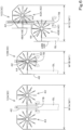
- raking machines 1C there are the following types of raking machines 1C (rakes 3C): a first type 1CA in which two rake units 43 rake grass toward the widthwise center of the raking machine 1C; a second type 1CB in which one rake unit 43 rakes grass toward one of the opposite sides of the raking machine 1C in the width direction; a third type 1CCin which two rake units 43 rake grass toward the widthwise center of the raking machine 1C and one of the opposite sides of the raking machine 1C in the width direction; and the like.
- the first type 1CA, the second type 1CB, and the third type 1CC have different widths (work widths) W1A, W1B, and W1C with which grass is to be raked.
- the first type 1CA is such that the two rake units 43 are disposed side-by-side with a certain distance (e.g., width of a swath GL) provided therebetween in the width direction of the raking machine 1C, and the swath GL is formed in the direction of travel of the raking machine 1C between the two rake units 43 whose rotation directions are different from each other.
- Grass (cut grass) captured by the two rake units 43 is discharged toward a position (central position) between the two rake units 43, and the swath GL is formed in the direction of travel the raking machine 1C.
- the second type 1CB is such that the rake unit 43 includes a plate-like member (a so-called "swath curtain") 48 for forming the swath GL, and the plate-like member 48 is disposed at a distance from a body 44 of the rake unit 43 in the width direction of the raking machine 1C. Grass (cut grass) captured by the rotating rake unit 43 is discharged toward the plate-like member 48 and hits the plate-like member 48, and the swath GL is formed in the direction of travel of the raking machine 1C.
- a plate-like member a so-called "swath curtain”
- the third type 1CC is such that two rake units 43A and 43B are provided on the right and left sides of the raking machine 1C such that the rake units 43A and 43B are displaced from each other in the front-rear direction of the raking machine 1C.
- a first plate-like member 48A for forming a temporary swath GL is located leftward of a body 44 of the forward rake unit 43A at a distance from body 44 of the forward rake unit 43A
- a second plate-like member 48B for forming the swath GL is located leftward of a body 44 of the rearward rake unit 43B at a distance from the body 44.
- Grass (cut grass) captured by the rotating rake unit 43A is discharged toward the first plate-like member 48A and hits the first plate-like member 48A, and the temporary swath GL is formed in the direction of travel of the raking machine 1C.
- the cut grass in the temporary swath GL is captured by the rotating rake unit 43B, discharged toward the second plate-like member 48B, and hits the second plate-like member 48B, and the swath GL is formed.
- the rake 3C includes a driver 49 to configure settings of the rake units 43 according to setting information.
- the setting information is setting information regarding the rake 3C and stored in advance in the controller 15 or the memory 16C.
- the setting information regarding the rake 3C includes, for example, setting information indicating height position(s) of the rake unit(s) 43 and/or setting information indicating a distance between the two rake units 43 or a distance between the rake unit 43 and the plate-like member 48.
- the driver 49 includes a first driver 49A that changes the height position(s) of the rake unit(s) 43 and a second driver 49B that changes the distance between the two rake units 43 or the distance between the rake unit 43 and the plate-like member 48.
- the first type 1CA, the second type 1CB, and the third type 1CC each include the first driver 49A and/or the second driver 49B.
- the first driver 49A is a driving mechanism including actuator(s) and/or cylinder(s), for example, and driven by the controller 15 to raise or lower the body(bodies) 44 and the rotor(s) 45 in the vertical direction, thus changing the height of the rake unit(s) 43 from an agricultural field surface (ground) to the height indicated by the setting information.
- the first driver 49A may change the height of the rake unit(s) 43 from the agricultural field surface (ground) by raising or lowering gauge wheel(s) 44a supporting the rake unit(s) 43.
- the first driver 49A can change the height from a reference position (first height) to a different position (second height) that is higher than the reference position, within a predetermined range.
- the second driver 49B in the first type 1CA changes the distance between the two rake units 43 in a horizontal direction.
- the second driver 49B in the second type 1CB changes the distance between the body 44 of the rake unit 43 and the plate-like member 48 in the horizontal direction.
- the second driver 49B in the third type 1CC changes at least the distance between the body 44 of the rake unit 43B and the second plate-like member 48B in the horizontal direction.
- the distance between the body 44 of the rake unit 43A and the first plate-like member 48A may be changeable or fixed.
- the second driver 49B is, for example, a driving mechanism including cylinder(s) and/or actuator(s).
- FIG. 21A is a diagram illustrating an example of the second driver and illustrates an example where a cylinder 490 changes the position of the plate-like member 48.
- FIG. 21B is a diagram illustrating another example of the second driver and illustrates an example where an actuator (e.g., a feed screw mechanism 494) changes the position of the plate-like member 48.
- an actuator e.g., a feed screw mechanism 494
- the cylinder 490 can be extended and retracted by a medium such as air or hydraulic pressure.
- a rod 490a is mounted on a third support arm 493 through a bracket 492b, and a tube 490b is mounted on a first support arm 491 which is fixed to the coupling frame 42, through a bracket 492a.
- the distance between the rake unit 43 and the plate-like member 48 in the horizontal direction can be changed as desired through the extension and retraction of the cylinder 490.
- the plate-like member 48 illustrated in FIG. 21A is replaced by the body 44 of the rake unit 43, the distance between the coupling frame 42 and the rake unit 43 in the horizontal direction can be changed as desired.
- the feed screw mechanism 494 includes a feed screw 494a, a mover 494b, and a motor 494c.
- the feed screw 494a is disposed along the first support arm 491 and the third support arm 493, and the opposite ends thereof are rotatably mounted on the first support arm 491 and the third support arm 493 by bearings 495.
- the mover 494b is screwed on the feed screw 494a and fixed to the third support arm 493.
- the motor 494c is fixed to the first support arm 491 and rotates the feed screw 494a.
- the feed screw 494a can be advanced by rotating the motor 494c forward and retreated by rotating the motor 494c reverse, thus changing, as desired, the distance between the rake unit 43 and the plate-like member 48 in the horizontal direction.
- the distance between the coupling frame 42 and the rake unit 43 in the horizontal direction can be changed as desired.
- the second driver 49B is driven by the controller 15 to change the distance between the two rake units 43 in the horizontal direction or the distance between the rake unit 43 and the plate-like member 48 in the horizontal direction to the distance indicated by the setting information.
- the second driver 49B can change the distance from a reference distance to an increased distance which is larger than the reference distance or a reduced distance which is smaller than the reference distance, within a predetermined range of distance.
- a machine information obtainer 89 obtains the machine information regarding the raking machine 1C
- the route creator 210 displays the machine information (type information such as the first type 1CA, the second type 1CB, or the third type 1CC and detailed information) regarding the raking machine 1C in a display field 212.
- the route creator 210 sets the work width W1A of the first type 1CA as the width for creation of the traveling route R2.
- the route creator 210 sets the work width W1B of the second type 1CB as the width for creation of the traveling route R2.
- the route creator 210 sets the work width W1C of the third type 1CC as the width for creation of the traveling route R2.
- the raking machine 1C includes at least one sensor 17 that obtains the state of grass or a swath GL in an agricultural field.
- the sensor 17 is, for example, an optical sensor, which is an imager such as a camera, a light detection and ranging (LiDAR), a time-of-flight (ToF) camera, and/or the like.
- the imager is a charge-coupled device (CCD) camera provided with CCD image sensors or a complementary-metal-oxide semiconductor (CMOS) camera provided with CMOS image sensors.
- CCD charge-coupled device
- CMOS complementary-metal-oxide semiconductor
- the LiDAR (laser sensor) detects a distance to a target by emitting pulsed infrared light or the like onto the target millions of times per second and measuring the time for the reflected pulsed infrared light to return to the LiDAR.
- the ToF camera detects a distance to a subject using a ToF of light.
- the sensor 17 is not limited and may be an imager, LiDAR (laser sensor), a ToF camera, or any combination of an imager, LiDAR (laser sensor), and/or a ToF camera may be mounted on the traveling vehicle 2C.
- the raking machine 1C includes two sensors 17. Specifically, the sensors 17 are imagers and provided at a front position and a rear position of the raking machine 1C.
- a front camera (second imager) 17A is provided at the front position of the raking machine 1C and captures an image of the state of grass in an agricultural field ahead of the raking machine 1C.
- a rear camera (first imager) 17B is provided at the rear position of the raking machine 1C and captures an image of the state of the agricultural field behind the raking machine 1C (especially the state of a formed swath GL).
- the front camera 17A is provided at a front end of the traveling vehicle 2C, but may be provided at any position, such as in the cabin 14, from which the front camera 17A can capture an image of a forward view.
- the rear camera 17B is provided at a rear end of the rake 3C, but may be provided at any position, such as in the cabin 14 or a position rearward of the traveling vehicle 2C, from which the rear camera 17B can capture an image of a formed swath GL.
- the controller 15 of the raking machine 1C changes the setting information regarding the rake 3C on the basis of the states obtained by the sensors 17. For example, the controller 15 changes the setting information regarding the rake 3C on the basis of imaging data obtained by the front camera 17A and/or imaging data obtained by the rear camera 17B. More specifically, the controller 15 changes the setting information regarding the rake 3C on the basis of imaging data of a work product obtained by the rear camera 17B and indicating the state of a formed swath GL. Alternatively or additionally, the controller 15 changes the setting information regarding the rake 3C on the basis of pre-work imaging data obtained by the front camera 17A before raking is performed and indicating the state of grass in an agricultural field.
- the controller 15 changes setting information indicating a clearance between a plate-like member 48 and a rake unit 43 on the basis of imaging data of a work product obtained by the rear camera 17B.
- the controller 15 changes the setting information indicating the clearance between the plate-like member 48 and the rake unit 43 on the basis of pre-work imaging data obtained by the front camera 17A.
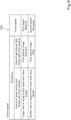
- the memory 16C includes first to fourth data tables TB1 to TB4.
- the first data table TB1 illustrated in FIG. 7 stores correspondences between imaging data obtained by the front camera 17A, imaging data obtained by the rear camera 17B, and setting information indicating the position of the plate-like member (swath curtain) 48.
- the first data table TB1 stores first setting information indicating that if the amount of grass indicated by the imaging data obtained by the front camera 17A is larger than or equal to a first upper limit value (large) or if the width (swath width) of a swath GL indicated by the imaging data obtained by the rear camera 17B is smaller than or equal to a first lower limit width (small), the plate-like member (swath curtain) 48 is pulled out to achieve the increased distance.
- the first data table TB1 also stores second setting information indicating that if the amount of grass indicated by the imaging data obtained by the front camera 17A is smaller than or equal to a first lower limit value (small) or if the width (swath width) of the swath GL indicated by the imaging data obtained by the rear camera 17B is larger than or equal to a first upper limit width (large) or if the swath GL indicated by the imaging data obtained by the rear camera 17B has a two-pile shape (a shape of two piles), the plate-like member 48 is pushed inward to achieve the reduced distance.
- the second data table TB2 illustrated in FIG. 8 stores correspondences between imaging data obtained by the front camera 17A and setting information indicating height of the rake unit 43, that is, height of the tines 47. More specifically, the second data table TB2 stores setting information indicating that if a captured image indicated by the imaging data obtained by the front camera 17A is a first feature image (if the state of grass is normal and an agricultural field is flat), the height of the tines 47 is set at the reference position (first height).
- the second data table TB2 also stores setting information indicating that if the captured image indicated by the imaging data obtained by the front camera 17A is a second feature image (if the state of grass is weak or soft) or a third feature image (if an agricultural field is not flat or is uneven), the height of the tines 47 is set at the different position (second height) which is higher than the reference position (first height).
- the third data table TB3 illustrated in FIG. 9 stores correspondences between imaging data obtained by the front camera 17A and the setting information indicating the travel speed of the traveling vehicle 2C. More specifically, the third data table TB3 stores setting information indicating that if the amount of grass indicated by the imaging data obtained by the front camera 17A is larger than or equal to a first upper limit value (large) or if a captured image indicated by the imaging data obtained by the front camera 17A is a third feature image (if an agricultural field is not flat or is uneven), the travel speed of the traveling vehicle 2C is set at a first speed which is lower than a predetermined specified speed.
- the third data table TB3 also stores setting information indicating that if the amount of grass indicated by the imaging data obtained by the front camera 17A is smaller than or equal to the first lower limit value (small), the travel speed of the traveling vehicle 2C is set at a second speed which is higher than the predetermined specified speed.
- the fourth data table TB4 illustrated in FIG. 10 stores correspondences between imaging data obtained by the rear camera 17B and the setting information indicating the rotation speed of the PTO shaft AX. More specifically, the fourth data table TB4 stores setting information indicating that if a captured image indicated by the imaging data obtained by the rear camera 17B is a fourth feature image (if the swath GL is triangular and hard), the rotation speed of the PTO shaft AX is set at a first rotation speed which is lower than a predetermined specified speed.
- the fourth data table TB4 also stores setting information indicating that if the captured image indicated by the imaging data obtained by the rear camera 17B is a third feature image (if an agricultural field is uneven), the rotation speed of the PTO shaft AX is set at a second rotation speed which is higher than the predetermined specified speed.
- the memory 16C may include at least one of the first to fourth data tables TB 1 to TB4.
- the traveling vehicle 2C of the raking machine 1C includes a PTO transmission 41 that changes the rotation speed of the PTO shaft AX under control of the controller 15. That is, the PTO transmission 41 changes the rotation speed of the PTO shaft AX, which is driven by power from the prime mover 11, to a desired rotation speed.
- the controller 15 of the raking machine 1C can set a plurality of adjustment modes for the raking in accordance with, for example, an operation instruction from an operator to a display 4C.
- the adjustment modes include first to fourth adjustment modes.
- a more appropriate swath GL is formed by adjusting the position of the plate-like member (swath curtain) 48 defining the distance to the body 44 using the first data table TB 1.
- a more appropriate swath GL is formed by automatically adjusting the height of the rake unit(s) 43 using the second data table TB2.
- a more appropriate swath GL is formed by automatically adjusting the travel speed of the traveling vehicle 2C using the third data table TB3.
- a more appropriate swath GL is formed by automatically adjusting the rotation speed of the PTO shaft AX using the fourth data table TB4.
- the display 4C displays icons corresponding to the first to fourth adjustment modes such that one of the icons that corresponds to a selected one of the first to fourth adjustment modes is highlighted and the other icons corresponding to unselected modes are not highlighted. The operator, therefore, can visually recognize the selected adjustment mode by looking at the icons on the display 4C.
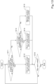
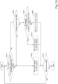
- FIG. 13 is a flowchart illustrating a control process by which the position of the plate-like member (swath curtain) 48 defining the distance is controlled on the basis of imaging data obtained by the front camera 17A.
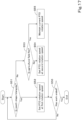
- FIG. 14 is a flowchart illustrating a control process by which the position of the plate-like member (swath curtain) 48 defining the distance is controlled on the basis of imaging data obtained by the rear camera 17B. It is assumed here that the raking machine 1C is of the second type 1CB illustrated in FIG. 6 and the first adjustment mode has been selected in accordance with an operation instruction from the operator to the display 4C.
- the controller 15 determines, using the first data table TB1 illustrated in FIG. 7 , whether the amount of grass indicated by the imaging data obtained by the front camera 17A is larger than or equal to the first upper limit value (S 11).
- the controller 15 determines that the amount of grass in the captured image is larger than or equal to the first upper limit value or if the controller 15 performs pattern matching between the captured image and images-for-determination of a plurality of types stored in the memory 16C in advance and determines that the captured image is the same as or similar to an image-for-determination corresponding to the first upper limit value or larger, for example, the controller 15 determines that the amount of grass is larger than or equal to the first upper limit value (YES in S11).
- an image GA1 is an example of an image when the amount of grass is normal (appropriate).
- An image GA2 is an example of an image when the amount of grass is large.
- An image GA3 is an example of an image when the amount of grass is small.
- the controller 15 determines that the amount of grass is larger than or equal to the first upper limit value (YES in S11)
- the controller 15 changes the setting information indicating the clearance between the plate-like member 48 and the rake unit 43 to the first setting information stored in the first data table TB1 illustrated in FIG. 7 to pull out the plate-like member (swath curtain) 48 with the second driver 49B and achieve the increased distance indicated by the first setting information (S 12).
- the controller 15 extends the cylinder 490 in the case of the second driver 49B illustrated in FIG. 21A or advances the feed screw 494a by rotating the motor 494c of the feed screw mechanism 494 forward in the case of the second driver 49B illustrated in FIG.
- the controller 15 may increase the clearance between the plate-like member 48 and the rake units 43 in accordance with an amount by which the first upper limit value is exceeded. That is, the increased distance may increase according to how much the first upper limit value is exceeded.
- the controller 15 determines whether the amount of grass indicated by the imaging data obtained by the front camera 17A is smaller than or equal to the first lower limit value (S 13).
- the controller 15 performs an image analysis on the imaging data (captured image) obtained by the front camera 17A and determines that the amount of grass in the captured image is smaller than or equal to the first lower limit value or if the controller 15performs pattern matching between the captured image and the images-for-determination of the plurality of types stored in the memory 16C in advance and determines that the captured image is the same as or similar to an image-for-determination corresponding to the first lower limit value or smaller, for example, the controller 15 determines that the amount of grass is smaller than or equal to the first lower limit value (YES in S 13).
- the controller 15 determines that the amount of grass is smaller than or equal to the first lower limit value (YES in S 13)
- the controller 15 changes the setting information indicating the clearance between the plate-like member 48 and the rake unit 43 to the second setting information stored in the first data table TB1 illustrated in FIG. 7 to push inward the plate-like member (swath curtain) 48 with the second driver 49B and achieve the reduced distance indicated by the second setting information (S14).
- the controller 15 retracts the cylinder 490 in the case of the second driver 49B illustrated in FIG. 21A or retreats the feed screw 494a by rotating the motor 494c of the feed screw mechanism 494 reverse in the case of the second driver 49B illustrated in FIG.
- the controller 15 may reduce the clearance between the plate-like member 48 and the rake unit 43 in accordance with an amount by which the clearance is short of the first lower limit value That is, the reduced distance may decrease according to how much the clearance is short of the first lower limit.
- the controller 15 determines that the amount of grass is not smaller than or equal to the first lower limit value (NO in S 13), on the other hand, the controller 15 uses the current setting information indicating the clearance between the plate-like member 48 and the rake unit 43 to maintain the clearance between the plate-like member (swath curtain) 48 and the rake unit 43 (S 15).
- the controller 15 determines whether the work has ended (S 16). For example, if the controller 15 receives an instruction to end raking from an operator (YES in S 16), the controller 15 ends the process. If there is no instruction to end the raking from the operator (NO in S 16), the controller 15 returns to step S 11.
- the controller 15 increases the clearance defined by the plate-like member 48 (swath curtain) since the amount of grass is large. If a captured image is the image GA3, the controller 15 reduces the clearance defined by the plate-like member 48 since the amount of grass is small. If a captured image is the image GA1, the controller 15 sets the clearance of the plate-like member 48 at a normal clearance since the amount of grass is appropriate.
- the controller 15 may make the determination in S11 illustrated in FIG. 13 on the basis of a start of transmission of power to the rake 3C from the PTO shaft AX or a start of driving of the rake units 43 and determine that the work has ended (YES in S16) on the basis of an end of the transmission of power to the rake 3C from the PTO shaft AX or an end of the driving of the rake unit 43.
- the controller 15 determines, using the first data table TB1 illustrated in FIG. 7 , whether the width (swath width) of a swath GL indicated by the imaging data obtained by the rear camera 17B is smaller than or equal to the first lower limit width (S21).
- the controller 15 performs an image analysis on the imaging data (captured image) obtained by the rear camera 17B and determines that the width (swath width) of the swath GL in the captured image is smaller than or equal to the first lower limit width or if the controller 15 performs pattern matching between the captured image and the images-for-determination of the plurality of types stored in the memory 16C in advance and determines that the captured image is the same as or similar to an image-for-determination corresponding to the first lower limit width or smaller, for example, the controller 15 determines that the width of the swath GL is smaller than or equal to the first lower limit width (YES in S21).
- an image GB1 is an example of an image when the swath GL has a correct shape.
- An image GB2 is an example of an image when the swath GL is triangular and hard.
- An image GB3 is an example of an image when the width of the swath GL is small.
- An image GB4 is an example of an image when the width of the swath GL is large.
- An image GB5 is an example of an image when the swath GL has a two-pile shape. Since the raking machine 1C is of the second type 1CB illustrated in FIG.
- the swath GL extends diagonally in an image captured by the rear camera 17B as illustrated in FIG. 12 .
- the controller 15 determines that the width of the swath GL is smaller than or equal to the first lower limit width (YES in S21)
- the controller 15 changes the setting information indicating the clearance between the plate-like member 48 and the rake unit 43 to the first setting information stored in the first data table TB1 illustrated in FIG. 7 to pull out the plate-like member 48 (swath curtain) with the second driver 49B and achieve the increased distance indicated by the first setting information (S22). More specifically, the controller 15 extends the cylinder 490 in the case of the second driver 49B illustrated in FIG. 21A or advances the feed screw 494a by rotating the motor 494c of the feed screw mechanism 494 forward in the case of the second driver 49B illustrated in FIG.
- the controller 15 may increase the clearance between the plate-like member 48 and the rake unit 43 in accordance with an amount by which the width is short of the first lower limit width.
- the controller 15 determines whether the width of the swath GL is not smaller than or equal to the first lower limit width (NO in S21), on the other hand, the controller 15 determines whether the swath GL indicated by the imaging data obtained by the rear camera 17B has a two-pile shape (S23).
- the controller 15 determines that the swath GL in the captured image has a two-pile shape or if the controller 15 performs pattern matching between the captured image and the images-for-determination of the plurality of types stored in the memory 16C in advance and determines that the captured image is the same as or similar to an image-for-determination corresponding to a swath GL having a two-pile shape, for example, the controller 15 determines that the swath GL has a two-pile shape (YES in S23).
- the controller 15 determines whether the width of the swath GL is larger than or equal to the first upper limit width (S24).
- the controller 15 performs an image analysis on the imaging data (captured image) obtained by the rear camera 17B and determines that the width of the swath GL in the captured image is larger than or equal to the first upper limit width or if the controller 15 performs pattern matching between the captured image and the images-for-determination of the plurality of types stored in the memory 16C in advance and determines that the captured image is the same as or similar to an image-for-determination corresponding to width of a swath GL being larger than or equal to the first upper limit width, for example, the controller 15 determines that the width of the swath GL is larger than or equal to the first upper limit width (YES in S24).
- the controller 15 determines that the width of the swath GL is larger than or equal to the first upper limit width (YES in S24) or that the swath GL has a two-pile shape (YES in S23), the controller 15 changes the setting information indicating the clearance between the plate-like member 48 and the rake unit 43 to the second setting information stored in the first data table TB1 illustrated in FIG. 7 to push inward the plate-like member (swath curtain) 48 with the second driver 49B and achieve the reduced distance indicated by the second setting information (S25). More specifically, the controller 15 retracts the cylinder 490 in the case of the second driver 49B illustrated in FIG.
- the controller 15 may reduce the clearance between the plate-like member 48 and the rake unit 43 in accordance with an amount by which the width is short of the first upper limit width.
- the controller 15 determines that the width of the swath GL is not smaller than or equal to the first lower limit width (NO in S24), on the other hand, the controller 15 employs the current setting information indicating the clearance between the plate-like member 48 and the rake unit 43 to maintain the clearance between the plate-like member (swath curtain) 48 and the rake unit 43 (S26).
- the controller 15 determines whether the work has ended (S27). If the controller 15 receives an instruction to end the raking from the operator (YES in S27), for example, the controller 15 ends the process. If there is no instruction to end the raking from the operator (NO in S27), the controller 15 returns to step S21.
- the controller 15 increases the clearance of the plate-like member 48 (swath curtain) since width of a swath GL is small. If a captured image is the image GB4, the controller 15 reduces the clearance of the plate-like member 48 since width of a swath GL is large. If a captured image is the image GB5, the controller 15 reduces the clearance of the plate-like member 48 since a swath GL has a two-pile shape. If a captured image is the image GB1, the controller 15 sets the clearance of the plate-like member 48 at a normal clearance since the amount of grass is appropriate.
- FIGS. 13 and 14 illustrate examples where the raking machine 1C is of the second type 1CB, the raking machine 1C may be of the first type 1CA, the third type 1CC, or another type.
- FIG. 15 is a flowchart illustrating a control process by which the height of the tines is controlled on the basis of imaging data obtained by the front camera 17A. It is assumed here that the raking machine 1C is of the first type 1CA illustrated in FIG. 6 and the second adjustment mode has been selected in accordance with an operation instruction from the operator to the display 4C.
- the controller 15 determines, using the second data table TB2 illustrated in FIG. 8 , whether the state of grass indicated by the imaging data obtained by the front camera 17A is normal (S31).
- the controller 15 performs an image analysis on the imaging data (captured image) obtained by the front camera 17A and determines that a captured image is the first feature image which indicates that the state of grass is normal or if the controller 15performs pattern matching between the captured image and the images-for-determination of the plurality of types stored in the memory 16C in advance and determines that the captured image is the same as or similar to an image-for-determination corresponding to the first feature image, for example, the controller 15 determines that the state of grass is normal (YES in S31).
- the image GA1 is an example of an image when the amount of grass is normal.
- the image GA2 is an example of an image when the amount of grass is large.
- the image GA3 is an example of an image when the amount of grass is small. Since the raking machine 1C is of the first type 1CA illustrated in FIG. 6 here and the rear camera 17B and the two rake units 43 are positioned such that the rear camera 17B is aligned with the center of the clearance between the rake units 43, the image captured by the rear camera 17B is an image showing the swath GL at the center as illustrated in FIG. 11 .
- the controller 15 determines whether an agricultural field is flat (S32). If the controller 15 performs an image analysis on the imaging data (captured image) obtained by the front camera 17A and determines that the captured image is the first feature image which indicates that the agricultural field is flat or if controller 15 performs pattern matching between the captured image and the images-for-determination of the plurality of types stored in the memory 16C in advance and determines that the captured image is the same as or similar to the image-for-determination corresponding to the first feature image, the controller 15 determines that the agricultural field is flat (YES in S32).
- the controller 15 determines that the state of grass is normal (YES in S31) and that the agricultural field is flat (YES in S32), the controller 15 changes setting information indicating the height of the rake units 43 from the agricultural field surface (ground) to third setting information of the second data table TB2, so that the height of the rake units 43 is set to the first height by the first driver 49A (S33).
- the first height may be a predetermined standard height closest to the agricultural field surface or any other desired height.
- the controller 15 determines that the state of grass is not normal (NO in S31) or that the agricultural field is not flat (NO in S32), on the other hand, the controller 15 changes the setting information indicating the height of the rake units 43 from the agricultural field surface (ground) to fourth setting information of the second data table TB2, so that the height of the rake units 43 is changed to a second height which is greater than the first height by the first driver 49A (S34).
- the controller 15 may determine that the agricultural field is not flat (NO in S32).
- the controller 15 may receive, from the assistor 84, positional information (topographic information) regarding places in the agricultural field detected by the position detector 60B in tedding (tedding step) cut grass in the agricultural field performed by the tedding machine 1B and determine, on the basis of the topographic information or using the topographic information as supplementary information, whether the agricultural field is flat.
- positional information topographic information
- the controller 15 determines whether the work has ended (S35). If receiving an instruction to end the raking from the operator (YES in S35), for example, the controller 15 ends the process. If there is no instruction to end the raking from the operator (NO in S35), the controller 15 returns to step S31.
- FIG. 16 is a flowchart illustrating a control process by which travel speed is controlled on the basis of imaging data obtained by the front camera 17A. It is assumed here that the raking machine 1C is of the second type 1CB illustrated in FIG. 6 and the third adjustment mode has been selected in accordance with an operation instruction from the operator to the display 4C.
- the controller 15 determines, using the third data table TB3 illustrated in FIG. 9 , whether the amount of grass indicated by the imaging data obtained by the front camera 17A is larger than or equal to the first upper limit value (S41).
- the controller 15 determines that the amount of grass in the captured image is larger than or equal to the first upper limit value or if the controller performs pattern matching between the captured image and the images-for-determination of the plurality of types stored in the memory 16C in advance and determines that the captured image is the same as or similar to the image-for-determination corresponding to the first upper limit value or larger, for example, the controller 15 determines that the amount of grass is larger than or equal to the first upper limit value (YES in S41).
- the controller 15 determines that the amount of grass is larger than or equal to the first upper limit value (YES in S41) If the controller 15 determines that the amount of grass is larger than or equal to the first upper limit value (YES in S41), the controller 15 changes the setting information indicating the travel speed of the traveling vehicle 2C to the setting information indicating the first speeds stored in the third data table TB3 illustrated in FIG. 9 , so that the travel speed of the traveling vehicle 2C is set at the first speed (S42). The controller 15 sets the travel speed of the traveling vehicle 2C at the first speed by controlling the prime mover 11 and the transmission 12. Noe that, if the controller 15 determines that the amount of grass is larger than or equal to the first upper limit value (YES in S41), the controller 15 may reduce the first speed of the traveling vehicle 2C in accordance with an amount by which the first upper limit value is exceeded. That is, the first speed of the traveling vehicle 2C decreases as the amount of grass becomes larger.
- the controller 15 determines whether the state of the agricultural field indicated by the imaging data obtained by the front camera 17A is flat (S43).
- the controller 15 determines that the state of the agricultural field in the captured image is flat or if the controller 15 performs pattern matching between the captured image and the images-for-determination of the plurality of types stored in the memory 16C in advance and determines that the captured image is the same as or similar to an image-for-determination indicating a flat agricultural field, for example, the controller 15 determines that the state of the agricultural field is flat (YES in S43).
- the controller 15 determines that the state of the agricultural field is not flat (NO in S43)
- the controller 15 changes the setting information indicating the travel speed of the traveling vehicle 2C to the setting information indicating the first speed stored in the third data table TB3 illustrated in FIG. 9 , so that the travel speed of the traveling vehicle 2C is at the first speed (S42).
- the controller 15 sets the travel speed of the traveling vehicle 2C at the second speed by controlling the prime mover 11 and the transmission 12.
- the controller 15 determines whether the amount of grass indicated by the imaging data obtained by the front camera 17A is smaller than or equal to the first lower limit value (S44).
- the controller 15 determines that the amount of grass in the captured image is smaller than or equal to the first lower limit value or if the controller 15 performs pattern matching between the captured image and the images-for-determination of the plurality of types stored in the memory 16C in advance and determines that the captured image is the same as or similar to the image-for-determination corresponding to the first lower limit value or smaller, for example, the controller 15 determines that the amount of grass is smaller than or equal to the first lower limit value (YES in S44).
- the controller 15 changes the setting information indicating the travel speed of the traveling vehicle 2C to the setting information indicating the second speed stored in the third data table TB3 illustrated in FIG. 9 to set the travel speed of the traveling vehicle 2C at the second speed (S45).
- the controller 15 determines that the amount of grass is not smaller than or equal to the first lower limit value (NO in S44), the controller 15 maintains the current setting information indicating the travel speed of the traveling vehicle 2C (S46).
- the controller 15 determines whether the work has ended (S47). If receiving an instruction to end the raking from the operator (YES in S47), for example, the controller 15 ends the process. If there is no instruction to end the raking from the operator (NO in S47), the controller 15 returns to step S41.
- the controller 15 determines that the captured image is the image GA2 (i.e., if the amount of grass is large) or that the agricultural field is not flat (is uneven), the controller 15 changes (reduces) the travel speed of the traveling vehicle 2C to the first speed. If the controller 15 determines that the captured image is the image GA3 (i.e., if the amount of grass is small), the controller 15 changes (increases) the travel speed of the traveling vehicle 2C to the second speed. If the controller 15 determines that the captured image is the image GA1 (i.e., if the amount of grass is normal), the controller 15 maintains the current travel speed of the traveling vehicle 2C.
- the image GA2 i.e., if the amount of grass is large
- the agricultural field is not flat (is uneven
- FIG. 17 is a flowchart illustrating a control process by which the rotation speed of the PTO shaft AX is controlled on the basis of imaging data obtained by the front camera 17A and imaging data obtained by the rear camera 17B. It is assumed here that the raking machine 1C is of the first type 1CA illustrated in FIG. 6 and the fourth adjustment mode has been selected in accordance with an operation instruction from the operator to the display 4C.
- the controller 15 determines, using the fourth data table TB4 illustrated in FIG. 10 , whether a captured image indicated by the imaging data obtained by the rear camera 17B is the fourth feature image (a swath GL is triangular and hard) (S51).
- the controller 15 determines that the captured image is the fourth feature image (YES in S51).
- the controller 15 determines that the imaging data (captured image) obtained by the rear camera 17B is the fourth feature image (YES in S51)
- the controller 15 changes setting information indicating the rotation speed of the PTO shaft AX to the setting information indicating the first rotation speed stored in the fourth data table TB4 illustrated in FIG. 10 , so that the rotation speed of the PTO shaft AX is set at the first rotation speed (S52).
- the controller 15 changes the rotation speed of the PTO shaft AX at the first rotation speed with the PTO transmission 41 by controlling the PTO transmission 41.
- the controller 15 determines whether the imaging data (captured image) obtained by the rear camera 17B is not the fourth feature image (NO in S51), on the other hand, the controller 15 determines whether the state of the agricultural field indicated by the imaging data obtained by the front camera 17A is flat (S53).
- the controller 15 performs an image analysis on the imaging data (captured image) obtained by the front camera 17A and determines that the state of the agricultural field in the captured image is flat or if the controller 15 performs pattern matching between the captured image and the images-for-determination of the plurality of types stored in the memory 16C in advance and determines that the captured image is the same as or similar to the image-for-determination indicating a flat agricultural field, for example, the controller 15 determines that the state of the agricultural field is flat (YES in S53). If the controller 15 determines that the state of the agricultural field is flat (YES in S53), the controller 15 maintains the setting information indicating the rotation speed of the PTO shaft AX to maintain the current rotation speed of the PTO shaft AX (S55).
- the controller 15 determines in S53 that the state of the agricultural field is not flat (NO in S53), on the other hand, the controller 15 changes the setting information indicating the rotation speed of the PTO shaft AX to the setting information indicating the second rotation speed stored in the fourth data table TB4 illustrated in FIG. 10 to change the rotation speed of the PTO shaft AX to the second rotation speed which is higher than the first rotation speed (S54).
- the controller 15 changes the rotation speed of the PTO shaft AX to the second rotation speed with the PTO transmission 41 by controlling the PTO transmission 41.
- the controller 15 determines whether the work has ended (S56). If the controller 15 receives an instruction to end the raking from the operator (YES in S56), for example, the controller 15 ends the process. If there is no instruction to end the raking from the operator (NO in S56), the controller 15 returns to step S51.
- the controller 15 determines that the image captured by the rear camera 17B is the image GB2 (i.e., if the swath GL is triangular and hard), the controller 15 changes (reduces) the rotation speed of the PTO shaft AX to the first rotation speed. If the controller 15 determines that the image captured by the front camera 17A is the third feature image (i.e., if the agricultural field is uneven), the controller 15 changes (increases) the rotation speed of the PTO shaft AX to the second rotation speed. In other cases (if the swath GL is not triangular and hard and the agricultural field is flat), the controller 15 maintains the current rotation speed of the PTO shaft AX.
- a working machine includes a traveling vehicle 2C, a rake 3C (working device) to rake grass in an agricultural field and form a swath, the rake 3C being coupled to the traveling vehicle 2C, a sensor 17 to obtain a state of the grass or the swath in the agricultural field, and a controller 15 to, when the rake 3C performs raking, change one or more pieces of setting information regarding the rake 3C based on the state obtained by the sensor 17.
- the controller 15 changes the setting information regarding the rake 3C based on the state obtained by the sensor 17, making it possible to easily make the products of raking performed by the rake 3C, that is, shapes of swaths, as uniform as possible. With this, an operator need not perform an operation to change the conditions in which the raking is performed by the rake 3C while visually checking the state of the grass or the swath in the agricultural field.
- the sensor 17 may include at least one imager (a front camera 17A and/or a rear camera 17B) to obtain imaging data by capturing an image of the state of the grass or the swath in the agricultural field.
- the controller 15 may be configured or programmed to change the one or more pieces of setting information regarding the rake 3C based on the imaging data obtained by the at least one imager. With this configuration, since the controller 15 changes the setting information regarding the rake 3C based on the imaging data captured by the at least one imager, the controller 15 can change the state of products of the raking performed by the rake 3C in real-time in accordance with the state of the grass or the swath in the agricultural field. As a result, an appropriate swath can be formed in accordance with the state of the grass or the swath in the agricultural field.
- the controller 15 may be configured or programmed to change the one or more pieces of setting information regarding the rake 3C based on the imaging data of a work product obtained by the first imager (rear camera 17B) and indicating the state of the formed swath.
- the controller 15 since the controller 15 changes the setting information regarding the rake 3C based on the imaging data of the work product obtained by the rear camera 17B and indicating the state of the formed swath, the controller 15 can change the state of products of the raking performed by the rake 3C in real-time in accordance with the state of the formed swath. As a result, an appropriate swath can be formed.
- the controller 15 may be configured or programmed to change the one or more pieces of setting information regarding the rake 3C based on the imaging data which is pre-work imaging data obtained by the second imager (front camera 17A) before raking is performed and indicating the state of the grass in the agricultural field.
- the controller 15 since the controller 15 changes the setting information regarding the rake 3C based on the pre-work imaging data obtained by the front camera 17A and indicating the state of the grass in the agricultural field, the controller 15 can change the state of products of the raking performed by the rake 3C in real-time in accordance with the state of the grass in the agricultural field before the raking. As a result, an appropriate swath can be formed.
- the controller 15 may be configured or programmed to change the one or more pieces of setting information regarding the rake 3C based on the imaging data of a work product obtained by the first imager (rear camera 17B) and indicating the state of the formed swath, and the imaging data which is pre-work imaging data obtained by the second imager (front camera 17A) before raking is performed and indicating the state of the grass in the agricultural field.
- the controller 15 since the controller 15 changes the setting information regarding the rake 3C based on the imaging data of the work product obtained by the rear camera 17B and indicating the state of the formed swath and the pre-work imaging data obtained by the front camera 17A and indicating the state of the grass in the agricultural field, the controller 15 can change the state of products of the raking performed by the rake 3C in real-time in accordance with the state of the grass in the agricultural field before the raking and the state of the formed swath. As a result, an appropriate swath can be formed.
- the rake 3C may include a rake unit 43 including a body 44, a rotor 45 rotatably supported by the body 44, tine arms (i.e., arms 46) coupled to the rotor 45 and radially extending from the rotor 45, one or more tines 47 coupled to each of the arms 46 and extending downward, and a plate-like member (swath curtain) 48 for forming the swath.
- the controller 15 may be configured or programmed to change one of the one or more pieces of setting information regarding the rake 3C that indicates a clearance between the plate-like member 48 and the rake unit 43 based on the imaging data of the work product.
- the controller 15 since the controller 15 changes the setting information indicating the clearance between the plate-like member 48 and the body 44 (rake unit 43) based on the imaging data of the work product indicating the state of the formed swath, the controller 15 can change the clearance between the plate-like member 48 and the body 44 (rake unit 43) in the rake 3C in real-time. As a result, an appropriate swath can be formed.
- the controller 15 may be configured or programmed to change one of the one or more pieces of setting information regarding the rake 3C that indicates a clearance between the plate-like member 48 and the rake unit 43 based on the pre-work imaging data.
- the controller 15 since the controller 15 changes the setting information indicating the clearance between the plate-like member 48 and the rake unit 43 based on the pre-work imaging data indicating the state of the grass in the agricultural field, the controller 15 can change the clearance between the plate-like member 48 and the rake unit 43 in the rake 3C in real-time. As a result, an appropriate swath can be formed.
- the rake 3C may include a rake unit 43.
- the controller 15 may be configured or programmed to change one of the one or more pieces of setting information regarding the rake 3C that indicates a distance between a lower end of the rake unit 43 and the agricultural field based on the pre-work imaging data.
- the rake 3C may include a rake unit 43.
- the controller 15 may be configured or programmed to change one of the one or more pieces of setting information regarding the rake 3C that indicates a travel speed of the traveling vehicle 2C based on the pre-work imaging data. With this configuration, since the controller 15 changes the setting information indicating the travel speed of the traveling vehicle 2C based on the pre-work imaging data indicating the state of the grass in the agricultural field, the travel speed of the traveling vehicle 2C can be changed in real-time. As a result, an appropriate swath can be formed.
- the traveling vehicle 2C may include a prime mover 11 and a power take-off shaft AX driven by power from the prime mover 11.
- the rake 3C may include a rake unit 43.
- the controller 15 may be configured or programmed to changes one of the one or more pieces of setting information regarding the rake 3C that indicates a rotation speed of the power take-off shaft AX based on the pre-work imaging data. With this configuration, since the controller 15 changes the setting information indicating the rotation speed of the power take-off shaft AX based on the pre-work imaging data indicating the state of the grass in the agricultural field, the rotation speed of the power take-off shaft AX can be changed in real-time. As a result, an appropriate swath can be formed.
- the controller 15 may be configured or programmed to change one of the one or more pieces of setting information regarding the rake 3C that indicates a rotation speed of the power take-off shaft AX based on the imaging data regarding the work product.
- the controller 15 since the controller 15 changes the setting information indicating the rotation speed of the power take-off shaft AX based on the imaging data of the work product indicating the state of the formed swath, the controller 15 can change the rotation speed of the power take-off shaft AX in real-time. As a result, an appropriate swath can be formed.
- first driver 49A changes the height positions of the rake units 43 in the above embodiment, height of the coupling frame 42, the tines 47, or the arms 46 may be changed, insofar as the height of the tines 47 is changed.
- the coupler 8 may be used instead of the first driver 49A, and the height positions of the rake units 43 may be changed using a raising and lowering function of the coupler 8.
- the controller 15 may perform, using artificial intelligence (AI), a process of analyzing imaging data of a work product obtained by the first imager (rear camera 17B) and indicating the state of a formed swath and pre-work imaging data obtained by the second imager (front camera 17A) and indicating the state of grass in an agricultural field.
- AI artificial intelligence
- the controller 15 may use, analyses and learning (i.e., machine learning) based on imaging data and training data (labeled data) to determine, for example, whether the amount of cut grass (grass) in an agricultural field is larger than or equal to the first upper limit value or smaller than or equal to the first lower limit value, whether the width (swath width) of a swath GL is larger than or equal to the first upper limit width or smaller than or equal to the first lower limit width, and/or whether a captured image is the same as or similar to the first to fourth feature images.
- analyses and learning i.e., machine learning based on imaging data and training data (labeled data) to determine, for example, whether the amount of cut grass (grass) in an agricultural field is larger than or equal to the first upper limit value or smaller than or equal to the first lower limit value, whether the width (swath width) of a swath GL is larger than or equal to the first upper limit width or smaller than or equal to the first lower limit width, and/or
- the controller 15 of the raking machine 1C may set priority levels for the first to fourth adjustment modes in accordance with an instruction about priority levels from the operator, for example, and enter an adjustment mode of the highest priority level.
- the first to fourth adjustment modes are: a mode to adjust the position of the plate-like member (swath curtain) 48 defining the distance; a mode to adjust the height of the rake unit(s) (tines) 43; a mode to adjust the travel speed of the traveling vehicle 2C; and a mode to adjust the rotation speed of the PTO shaft AX, respectively.
- the controller 15 of the raking machine 1C may disable, among the first to fourth adjustment modes, adjustment modes that are not applicable depending on whether the rake 3C is of the first type 1CA, the second type 1CB, or the third type 1CC.
- the first type 1CA for example, since the plate-like member (swath curtain) 48 is not provided, the first adjustment mode is disabled.
- the second adjustment mode is disabled.
- the following arrangement may be used: if an error occurs during the image analysis or the pattern matching in S11 or S13 illustrated in FIG. 13 , S21, S23, or S24 illustrated in FIG. 14 , S31 or S32 illustrated in FIG. 15 , or S41, S43, or S44 illustrated in FIG.
- the controller 15 of the raking machine 1C maintains the current setting information regarding the rake 3C, temporarily refrains from changing the setting information regarding the rake 3C, and stores occurrence of the error in the memory 16C. In this case, even if an unforeseen error occurs, it is possible to eliminate or reduce the likelihood that the rake 3C will perform an unexpected operation.
- the raking machine 1C includes a position detector 60C (positioning device).
- the tedding machine 1B includes a rear camera 17B that captures an image of grass (cut grass) tedded in an agricultural field and, during tedding, stores the captured image of the grass (cut grass) tedded in the agricultural field and positional information at the time of the image capturing such that the captured image and the positional information are associated with each other or transmits the captured image and the positional information to an external device (a server etc.) to store the captured image and the positional information in the external device.
- an external device a server etc.
- the controller 15 of the raking machine 1C may obtain one or more pieces of imaging data in a tedding step preceding a raking step which are associated with one or more pieces of positional information indicating position(s) at which the one or more pieces of imaging data were obtained, and change the setting information regarding the rake 3C (working device) based on one of the obtained one or more pieces of imaging data that corresponds to one of the one or more pieces of positional information that matches measured position information obtained by the position detector 60C of the raking machine 1C.
- the controller 15 changes the setting information regarding the rake 3C (working device) based on imaging data obtained in the tedding step preceding the raking process, the state of products of the raking performed by the rake 3C (working device) can be changed in accordance with the state of grass or swath in an agricultural field. Therefore, an appropriate swath can be formed in accordance with the state of grass or a swath in the agricultural field.
- the raking machine 1C includes a position detector 60C (positioning device), a memory 16C, and a communicator 82C.
- the controller 15 During raking performed by the rake 3C in an agricultural field, that is, during formation of a swath GL, the controller 15 generates work product record data in which measured position information obtained by the position detector 60C, imaging data (e.g., image(s) captured by the rear camera 17B) of the work products, and time information (timestamp(s)) are associated with each other, and stores the record data in the memory 16C.
- imaging data e.g., image(s) captured by the rear camera 17B
- time information timestamp(s)
- the controller 15 then causes the communicator 82C to transmit the record data stored in the memory 16C to an external information processor (e.g., the external device 83 or the assistor 84) to store the record data in the external device 83 or the assistor 84.
- an external information processor e.g., the external device 83 or the assistor 84
- the products of raking can be checked based on the record data of the raking machine 1C using the external device 83 or the assistor 84.
- the controller 15 since the controller 15 generates work product record data in which measured position information obtained by the position detector 60C (positioning device) and imaging data of the work products are associated with each other, stores the record data in the memory 16C, and causes the communicator 82C to transmit the record data stored in the memory 16C to an external information processor, the baling machine 1D can effectively use the work product record data in a baling step (i.e., when grass is formed into rolls) after the raking step.
- a baling step i.e., when grass is formed into rolls
- the grass management system may also include a third physical quantity detector 50.
- the third physical quantity detector 50 detects a physical quantity(quantities) relating to grass such as component(s) of grass (moisture content and/or protein).
- the third physical quantity detector 50 is provided in or on the raking machine 1C.
- the third physical quantity detector 50 obtains at least moisture value(s) (third moisture value(s)) of grass at the time of raking performed by the raking machine 1C.
- the third physical quantity detector 50 is provided in or on rake unit(s) 43 and obtains the third moisture value(s) of cut grass (grass) at the time of raking.
- the third physical quantity detector 50 is a spectrometer, for example, and analyzes the moisture in grass by emitting light having a certain frequency onto the grass and receiving light reflected from the grass.
- the third physical quantity detector 50 is connected to the controller 15 or the memory 16C of the traveling vehicle 2C.
- the controller 15 stores the third moisture value(s) obtained by the third physical quantity detector 50 and position(s) at which raking was performed (hereinafter "raking positions", latitude and longitude) detected by the position detector 60C in the memory 16C as map data regarding the third moisture values in which the third moisture values and the raking positions are associated with each other. As illustrated in FIG. 19 , the memory 16C stores map data regarding third moisture values in which detected raking positions and the third moisture values are associated with each other.
- the third physical quantity detector 50 When the controller 15 or the third physical quantity detector 50 detects a start of traveling of the traveling vehicle 2C, a start of transmission of power to the rake 3C from the PTO shaft AX, or a start of driving of the rake units 43, for example, the third physical quantity detector 50 begins to obtain third moisture values. When the controller 15 or the third physical quantity detector 50 detects an end of the traveling of the traveling vehicle 2C, an end of the transmission of power to the rake 3C from the PTO shaft AX, or an end of the driving of the rake units 43, the third physical quantity detector 50 stops obtaining the third moisture values.
- the start and the stop of the obtaining of the third moisture values by the third physical quantity detector 50 are not limited to the above example, and the obtaining of the third moisture values may start or stop when the manipulator provided near the operator's seat of the traveling vehicle 2C is operated or when a start or a stop of the mowing is requested using the display, the switch, or the like provided near the operator's seat.
- a switch for requesting the third physical quantity detector 50 to start or stop obtaining the third moisture values may be provided near the operator's seat.
- the controller 15 may add the third moisture values to the work product record data and cause the communicator 82C to transmit the record data to an external information processor.
- the baling machine 1D can use the work product record data more effectively in the baling step (i.e., when grass is formed into rolls) after the raking step.
- the traveling vehicle 2C includes the controller 15 in the above embodiment and the variations
- the rake 3C (working device) may include the controller 15. With this configuration, the same effects as in the above embodiments and the variations can be achieved.
Landscapes
- Life Sciences & Earth Sciences (AREA)
- Environmental Sciences (AREA)
- Physics & Mathematics (AREA)
- General Physics & Mathematics (AREA)
- Harvester Elements (AREA)
- Guiding Agricultural Machines (AREA)
Abstract
A raking machine (1C) (working machine) includes a traveling vehicle (2C), a rake (3C) (working device) that is coupled to the traveling vehicle (2C) and that rakes grass in an agricultural field and forms a swath, a sensor (17) that obtains a state of the grass or the swath (GL) in the agricultural field, and a controller that changes, when the rake (3C) performs raking, setting information regarding the rake (3C) based on the state obtained by the sensor (17).
Description
- The present invention relates to a working machine, such as a raking machine that performs raking, and a working device.
-
Japanese Unexamined Patent Application Publication No. 2020-096543 Patent Literature 1 also discloses a process where swaths formed as a result of raking are introduced into a roll baler or the like and the roll baler bales the swaths into a certain shape and discharges roll bales onto an agricultural field. - In practice, however, when cut grass in an agricultural field is raked as in
Patent Literature 1, shapes of swaths vary depending on, for example, the amount of grass before the raking. When the shapes of the swaths are not constant (vary), it might be difficult to, for example, introduce the swaths into the roll baler and intervals of roll bales discharged from the roll baler might be unstable. - The present invention has been made to address this problem in the example of the related art and aims to easily make shapes of swaths and the like uniform.
- Technical solutions in the present invention for addressing the technical problem are characterized as follows.
- A working machine according to an aspect of the present invention includes a traveling vehicle, a working device to rake grass in an agricultural field and form a swath, the working device being coupled to the traveling vehicle, a sensor to obtain a state of the grass or the swath in the agricultural field, and a controller to, when the working device performs raking, change one or more pieces of setting information regarding the working device based on the state obtained by the sensor.
- The sensor may include at least one imager to obtain imaging data by capturing an image of the state of the grass or the swath in the agricultural field. The controller may be configured or programmed to change the one or more pieces of setting information regarding the working device based on the imaging data obtained by the at least one imager.
- The at least one imager may be a first imager to obtain imaging data by capturing an image of the state of the swath formed by the working device. The controller may be configured or programmed to change the one or more pieces of setting information regarding the working device based on the imaging data of a work product obtained by the first imager and indicating the state of the formed swath.
- The at least one imager may be a second imager to obtain imaging data by capturing an image of the state of the grass in the agricultural field. The controller may be configured or programmed to change the one or more pieces of setting information regarding the working device based on the imaging data which is pre-work imaging data obtained by the second imager before raking is performed and indicating the state of the grass in the agricultural field.
- The at least one imager may include a first imager to obtain imaging data by capturing an image of the state of the swath formed by the working device and a second imager to obtain imaging data by capturing an image of the state of the grass in the agricultural field. The controller may be configured or programmed to change the one or more pieces of setting information regarding the working device based on the imaging data of a work product obtained by the first imager and indicating the state of the formed swath, and the imaging data which is pre-work imaging data obtained by the second imager before raking is performed and indicating the state of the grass in the agricultural field.
- The working device may include a rake unit including a body, a rotor rotatably supported by the body, tine arms coupled to the rotor and radially extending from the rotor, one or more tines coupled to each of the tine arms and extending downward, and a plate-like member to form the swath. The controller may be configured or programmed to change one of the one or more pieces of setting information regarding the working device that indicates a clearance between the plate-like member and the body based on the imaging data of the work product.
- The working device may include a rake unit including a body, a rotor rotatably supported by the body, tine arms coupled to the rotor and radially extending from the rotor, one or more tines coupled to each of the tine arms and extending downward, and a plate-like member to form the swath. The controller may be configured or programmed to change one of the one or more pieces of setting information regarding the working device that indicates a clearance between the plate-like member and the body based on the pre-work imaging data.
- The working device may include a rake unit including a body, a rotor rotatably supported by the body, tine arms coupled to the rotor and radially extending from the rotor, and one or more tines coupled to each of the tine arms and extending downward. The controller may be configured or programmed to change one of the one or more pieces of setting information regarding the working device that indicates a distance between a lower end of the rake unit and the agricultural field based on the pre-work imaging data.
- The working device may include a rake unit including a body, a rotor rotatably supported by the body, tine arms coupled to the rotor and radially extending from the rotor, and one or more tines coupled to each of the tine arms and extending downward. The controller may be configured or programmed to change one of the one or more pieces of setting information regarding the working device that indicates travel speed of the traveling vehicle based on the pre-work imaging data.
- The traveling vehicle may include a prime mover and a power take-off shaft driven by power from the prime mover. The working device may include a rake unit including a body, a rotor which is rotatably supported by the body and to which power from the power take-off shaft is transmitted, tine arms coupled to the rotor and radially extending from the rotor, and one or more tines coupled to each of the tine arms and extending downward. The controller may be configured or programmed to change one of the one or more pieces of setting information regarding the working device that indicates a rotation speed of the power take-off shaft based on the pre-work imaging data.
- The traveling vehicle may include a prime mover and a power take-off shaft driven by power from the prime mover. The working device may include a rake unit including a body, a rotor which is rotatably supported by the body and to which power from the power take-off shaft is transmitted, tine arms coupled to the rotor and radially extending from the rotor, and one or more tines coupled to each of the tine arms and extending downward. The controller may be configured or programmed to change one of the one or more pieces of setting information regarding the working device that indicates a rotation speed of the power take-off shaft based on the imaging data of the work product.
- The working machine may further include a positioning device to obtain measured position information. The controller may be configured or programmed to obtain one or more pieces of imaging data in a tedding step preceding a raking step, the one or more pieces of imaging data being associated with one or more pieces of positional information indicating one or more positions at which the one or more pieces of imaging data have been obtained, and change the one or more pieces of setting information regarding the working device based on one of the obtained one or more pieces of imaging data that corresponds to one of the one or more pieces of positional information that matches the measured position information obtained by the positioning device.
- The working machine may further include a positioning device to obtain measured position information, a memory, and a communicator. The controller may be configured or programmed to generate work product record data in which the measured position information obtained by the positioning device and the imaging data of the work product are associated with each other, cause the memory to store the work product record data, and cause the communicator to transmit the work product record data stored in the memory to an external information processor.
- A working device according to another aspect of the present invention includes a rake unit to rake grass in an agricultural field and form a swath, the rake unit being couplable to a traveling vehicle. The rake unit may be operable to, based on a state of the grass or the swath in the agricultural field, change a condition in which the swath is formed.
- The rake unit may be operable to, based on imaging data obtained by capturing an image of the state of the grass or the swath in the agricultural field, change the condition in which the swath is formed.
- The rake unit may be operable to, based on imaging data of a work product indicating the state of the swath formed by the rake unit, a condition in which a next swath is formed.
- The rake unit may be operable to, based on pre-work imaging data indicating the state of the grass in the agricultural field before raking is performed by the rake unit, change a condition in which a next swath is formed.
- The rake unit may include a body, a rotor rotatably supported by the body, tine arms coupled to the rotor and radially extending from the rotor, one or more tines coupled to each of the tine arms and extending downward, and a plate-like member to form the swath. The plate-like member may be operable to change a clearance between the plate-like member and the body based on the imaging data or the pre-work imaging data.
- With the present invention, shapes of swaths and the like can be easily made uniform.
- The above and other elements, features, steps, characteristics and advantages of the present invention will become more apparent from the following detailed description of the preferred embodiments with reference to the attached drawings.
- A more complete appreciation of preferred embodiments of the present invention and many of the attendant advantages thereof will be readily obtained as the same becomes better understood by reference to the following detailed description when considered in connection with the accompanying drawings described below.
-
FIG. 1 is a diagram illustrating a grass management system. -
FIG. 2A is a side view of the entirety of a raking machine. -
FIG. 2B is a plan view of the entirety of the raking machine. -
FIG. 3 is a diagram illustrating a creation screen. -
FIG. 4 is a diagram illustrating another creation screen. -
FIG. 5 is a diagram illustrating a setting screen. -
FIG. 6 is a diagram illustrating types of raking machine. -
FIG. 7 is a diagram illustrating a first data table. -
FIG. 8 is a diagram illustrating a second data table. -
FIG. 9 is a diagram illustrating a third data table. -
FIG. 10 is a diagram illustrating a fourth data table. -
FIG. 11 is a diagram illustrating an example of images of grass or swaths. -
FIG. 12 is a diagram illustrating another example of the images of swaths. -
FIG. 13 is a flowchart illustrating a control process where the position of a swath curtain defining distance is controlled on the basis of imaging data obtained by a front camera. -
FIG. 14 is a flowchart illustrating a control process where the position of the swath curtain defining distance is controlled on the basis of imaging data obtained by a rear camera. -
FIG. 15 is a flowchart illustrating a control process where height of tines is controlled on the basis of imaging data obtained by the front camera. -
FIG. 16 is a flowchart illustrating a control process where travel speed is controlled on the basis of imaging data obtained by the front camera. -
FIG. 17 is a flowchart illustrating a control process where rotation speed of a power take-off (PTO) shaft is controlled on the basis of imaging data obtained by the front camera and imaging data obtained by the rear camera. -
FIG. 18 is a schematic diagram illustrating how a controller determines imaging data through machine learning. -
FIG. 19 is a diagram illustrating a relationship between raking positions and third moisture values. -
FIG. 20 is a diagram illustrating the entirety of a tractor. -
FIG. 21A is a diagram illustrating an example of a second driver. -
FIG. 21B is a diagram illustrating another example of the second driver. - The preferred embodiments will now be described with reference to the accompanying drawings, wherein like reference numerals designate corresponding or identical elements throughout the various drawings. The drawings are to be viewed in an orientation in which the reference numerals are viewed correctly.
- An embodiment of the present invention will be described hereinafter on the basis of the drawings.
-
FIG. 1 is a diagram illustrating the entirety of a grass management system. The grass management system is a system that manages matters relating to grass planted in an agricultural field. - Grass grown in an agricultural field is addressed by working machines of at least one type.
FIG. 1 illustrates working machines of four types. The working machines of four types are a mowingmachine 1A, a tedding machine 1B, a rakingmachine 1C, and a balingmachine 1D. Themowing machine 1A mows grass in an agricultural field and discharges cut grass to the outside. The tedding machine 1B teds the grass (cut grass) in the agricultural field. The rakingmachine 1C forms swaths by raking the grass tedded in the agricultural field. The balingmachine 1D collects the grass in the form of swaths and bales the collected grass into a certain shape, namely, for example, a cylindrical shape or a cuboid shape. - The
mowing machine 1A includes a travelingvehicle 2A and amower 3A coupled to the travelingvehicle 2A. The tedding machine 1B includes a travelingvehicle 2B and atedder 3B coupled to the travelingvehicle 2B. The rakingmachine 1C includes a travelingvehicle 2C and arake 3C coupled to the travelingvehicle 2C. The balingmachine 1D includes a travelingvehicle 2D and abaler 3D coupled to the travelingvehicle 2D. - The traveling
vehicles vehicles - As illustrated in
FIG. 20 , the traveling vehicles (tractors) 2A, 2B, 2C, and 2D each include avehicle body 10, aprime mover 11, and atransmission 12. Thevehicle body 10 is provided with a travelingdevice 13. The travelingdevice 13 includes front wheels and rear wheels. The travelingdevice 13 may be a crawler device. Theprime mover 11 is a diesel engine, an electric motor, or the like and is a diesel engine in this embodiment. Thetransmission 12 can change propelling force of the travelingdevice 13 and switch forward traveling and backward traveling of the travelingdevice 13. In addition, acoupler 8 including a three-point linkage is provided in a rear portion of thevehicle body 10. A working device (e.g., an implement) can be removably attached to thecoupler 8. The working device is, for example, themower 3A, thetedder 3B, therake 3C, or thebaler 3D. When a working device is coupled to thecoupler 8, thevehicle body 10 can tow the working device. The travelingvehicles prime mover 11 or the like and can transmit power of the PTO shaft to the working device. The travelingvehicles cabin 14 including an operator's seat therein. - As illustrated in
Fig. 1 , the travelingvehicles controller 15. Thecontroller 15 controls a traveling system and a working system of each of the travelingvehicles vehicle body 10, and the like. For example, thecontroller 15 raises or lowers the working device on the basis of use of the operation actuators (operation signals) and controls diesel engine speed on the basis of an acceleration pedal sensor. Thecontroller 15 may be any controller that controls the working system and the traveling system of each of the travelingvehicle - As illustrated in
FIGS. 2A and2B , therake 3C includes acoupling frame 42 coupled to thecoupler 8 of the travelingvehicle 2C and rakeunits 43 coupled to thecoupling frame 42.FIGS. 2A and2B illustrate an example where tworake units 43 are coupled to thecoupling frame 42. Therake units 43 each include abody 44 coupled to thecoupling frame 42, arotor 45 rotatably supported by thebody 44, arms (tine arms) 46 coupled to therotor 45, and one ormore tines 47 coupled to each of thearms 46. The intervals between thetines 47 of therake 3C are shorter than those between forks of thetedder 3B. Thetines 47 are, for example, bifurcated members. Power from a PTO shaft AX is transmitted to each of therotors 45 via a drivingshaft 28C supported by thecoupling frame 42, thus rotating therotors 45. The rotation of therotors 45 causes thearms 46 to rotate, and thetines 47 rake grass. That is, the rotation of therotors 45 causes thetines 47 to rotate, and thetines 47 rake grass. The configuration of therake 3C is not limited to the above, provided that therake 3C rakes grass. The number ofrake units 43, for example, may be one, or three or more. Therake units 43 may be of a rotary type in which a rotor to whichtines 47 are attached rotates about a vertical axis, a belt/chain type in which tines 47 are attached to a belt or a chain that rotates, or any other type. - As illustrated in
FIGS. 1 and20 , the grass management system includes at least oneposition detector 60 capable of detecting the position of a working machine. The at least oneposition detector 60 includes aposition detector 60A that detects the position of themowing machine 1A. The at least oneposition detectors 60 includes aposition detector 60B that detects the position of the tedding machine 1B. The at least oneposition detectors 60 includes aposition detector 60C that detects the position of the rakingmachine 1C. The at least oneposition detectors 60 includes aposition detector 60D that detects the position of the balingmachine 1D. - The
position detectors position detector 60A is mounted on a roof of thecabin 14 of the travelingvehicle 2A. Theposition detector 60B is mounted on a roof of thecabin 14 of the travelingvehicle 2B. Theposition detector 60C is mounted on a roof of thecabin 14 of the travelingvehicle 2C. Theposition detector 60D is mounted on a roof of thecabin 14 of the travelingvehicle 2D. That is, theposition detectors position detectors cabin 14, a position on the tractor (traveling vehicle) at which each of theposition detectors - The
position detectors position detectors position detectors - Since the
position detectors mowing machine 1A, the tedding machine 1B, the rakingmachine 1C, and the balingmachine 1D, respectively, a position during mowing, a position during tedding, a position during raking, and a position during baling can be individually detected. A memory (first memory) 16A of the travelingvehicle 2A stores the position(s) during the mowing. Amemory 16B of the travelingvehicle 2B stores the position(s) during the tedding. Amemory 16C of the travelingvehicle 2C stores the position(s) during the raking. A memory (second memory) 16D of the travelingvehicle 2D stores the position(s) during the baling. - As illustrated in
FIG. 1 , the grass management system includes a firstphysical quantity detector 81. The firstphysical quantity detector 81 detects physical quantity(quantities) relating to grass such as component(s) of grass (moisture content and/or protein). The firstphysical quantity detector 81 is provided in or on themowing machine 1A. The firstphysical quantity detector 81 obtains at least moisture value(s) (first moisture value(s)) of grass at the time of mowing performed by the mowingmachine 1A. - The first
physical quantity detector 81 is provided in or on themower 3A and obtains the first moisture value(s) of grass when the grass is mowed. The firstphysical quantity detector 81 is a spectrometer, for example, and analyzes the moisture in grass by emitting light having a certain frequency onto the grass and receiving light reflected from the grass. The firstphysical quantity detector 81 is connected to thecontroller 15 or thememory 16A of the travelingvehicle 2A. Thecontroller 15 stores the first moisture value(s) obtained by the firstphysical quantity detector 81 and position(s) at which grass was mowed (hereinafter "mowing positions", latitude and longitude) detected by theposition detector 60A in thememory 16A as map data regarding the first moisture values in which the first moisture values and the mowing positions are associated with each other. - As illustrated in
FIG. 1 , the travelingvehicle 2A includes acommunicator 82A. Thecommunicator 82A is connected to at least thememory 16A and outputs the map data regarding the first moisture values (the mowing positions and the first moisture values) stored in thememory 16A to anexternal device 83. Theexternal device 83 is a mobile terminal such as a smartphone, a tablet, or a personal digital assistant (PDA). Thecommunicator 82A is a short-distance communicator or a communicator that performs wireless communication over a mobile telephone communication network, a data communication network, or the like. Thecommunicator 82A has a communication function by which thecommunicator 82A is connected to theexternal device 83 such that the map data regarding the first moisture values is transmitted to an assistor 84 (described later) through direct communication or indirect communication, and outputs the mowing positions and the first moisture values to theexternal device 83. - As illustrated in
FIG. 1 , the grass management system includes theassistor 84. Theassistor 84 is, for example, a personal computer, a server, or the like owned by an administrator. - The
assistor 84 includes aprocessing unit 84a such as a central processing unit (CPU), a display unit (display) 84b, and amemory unit 84c such as a nonvolatile memory. Theassistor 84 also includes a connector to which theexternal device 83 can be connected. Thedisplay unit 84b displays various pieces of information and is achieved by a liquid crystal panel or the like. - The grass management system also includes a
creation assist unit 85. Thecreation assist unit 85 includes electrical and electronic component(s) of theassistor 84 and/or program(s) incorporated in theprocessing unit 84a (assistor 84) and/or the like. Thecreation assist unit 85 assists creation of work plan(s) for the working machine(s). For example, the creation assistunit 85 assists creation of at least one of the following: a work plan for mowing performed by the mowingmachine 1A; a work plan for tedding performed by the tedding machine 1B; a work plan for raking performed by the rakingmachine 1C; and a work plan for baling performed by the balingmachine 1D. - When the administrator or another person operates the
assistor 84, the creation assistunit 85 displays, on thedisplay unit 84b, a creation screen M1 for creating a work plan as illustrated inFIG. 3 . The creation screen M1 is a screen for setting a work plan in a certain agricultural field, that is, a predetermined plot.FIG. 3 illustrates the creation screen M1 for setting a work plan in an agricultural field A. An agricultural field owned by the administrator or another person is registered in advance in theassistor 84, and when agricultural fields are registered in advance, a work plan can be set for each of the agricultural fields. For convenience of description, it is assumed in the following description that a work plan is created for one agricultural field (agricultural field A). - The
creation assist unit 85 displays, in the creation screen M1, awork item field 103, where the work items "mowing (mower)", "tedding (tedder)", "raking (rake)", and "baling (baler)" relating to grass-related work are displayed. The work items displayed in thework item field 103 are selectable. It is apparent fromFIG. 3 that, because a work item selected inFIG. 3 is mowing, the creation screen M1 is a screen for setting a work plan beginning with mowing. - The
creation assist unit 85 displays a planneddate field 105 which displays dates inputted by the administrator on which mowing (mower), tedding (tedder), raking (rake), and baling (baler) are to be performed, for example. - Although the administrator or another person sets desired relationships between the work items and the dates in the planned
date field 105 by operating theassistor 84 in the above embodiment, the creation assistunit 85 may automatically create relationships between the work items and the dates in the planneddate field 105. When the administrator or another person selects a button (register button) 106 displayed in the creation screen M1, the work plan set in the creation screen M1 is stored in thememory unit 84c of theassistor 84. - As described above, the creation assist
unit 85 assists creation of a work plan. This makes it possible to set dates, work periods, and/or the like for a series of work items including mowing, tedding, raking, and then baling. - As described above, the mowing
machine 1A can obtain the mowing positions and the first moisture values at the time of mowing. When theexternal device 83 is connected to thecommunicator 82A of themowing machine 1A, the mowing positions and the first moisture values detected at the time of mowing can be stored in theexternal device 83. When theexternal device 83 is connected to theassistor 84, thememory unit 84c of theassistor 84 can obtain and store the mowing positions and the first moisture values stored in theexternal device 83. - The
creation assist unit 85 can assist, using the mowing positions and the first moisture values thus detected at the time of the mowing, creation of a work plan for another working machine (the tedding machine 1B, the rakingmachine 1C, or the balingmachine 1D) used after the mowing. -
FIG. 4 illustrates a creation screen M2 displayed when tedding is selected in thework item field 103 after mowing is set as illustrated inFIG. 3 . The creation screen M2 illustrated inFIG. 4 displays thework item field 103 and the planneddate field 105 as inFIG. 3 . - When creating a work plan, the creation assist
unit 85 displays, for example, amoisture map 110A in the creation screen M2. As illustrated inFIG. 4 , themoisture map 110A is a map created by amoisture map creator 87. Themoisture map creator 87 includes electrical and electronic component(s) of theassistor 84 and/or program(s) incorporated in theprocessing unit 84a (assistor 84) and/or another unit. Themoisture map creator 87 creates themoisture map 110A for the agricultural field on the basis of the first moisture values and the mowing positions. - Accordingly, the
moisture map 110A at the time of mowing is displayed in the creation screen M2 for setting a work plan at least after mowing. Therefore, in the case where the administrator or another person can manually change the relationships between the work items and the dates in the planneddate field 105 in the creation screen M2 as desired, the administrator or another person can change the date of tedding with reference to themoisture map 110A as desired. - Although the administrator or another person changes as desired the date shown in the planned
date field 105 in the creation screen M2 while looking at themoisture map 110A displayed in the creation screen M2 in the above embodiment, the creation assistunit 85 may set the date of work in a work plan based on the first moisture values. - As illustrated in
FIG. 1 , the grass management system includes a secondphysical quantity detector 150. As with the firstphysical quantity detector 81, the secondphysical quantity detector 150 detects physical quantity(quantities) relating to grass, such as component(s) of grass (moisture content and/or protein). The secondphysical quantity detector 150 is provided in or on the tedding machine 1B. The secondphysical quantity detector 150 obtains at least moisture value(s) (second moisture value(s)) of grass at the time of tedding performed by the tedding machine 1B. - The second
physical quantity detector 150 is provided in or on thetedder 3B and obtains the second moisture value(s) of grass when the grass is tedded. The secondphysical quantity detector 150 is a spectrometer, for example, and analyzes the moisture in grass by emitting light having a certain frequency onto the grass and receiving light reflected from the grass. The secondphysical quantity detector 150 is connected to thecontroller 15 or thememory 16B of the travelingvehicle 2B. Thecontroller 15 stores the second moisture value(s) obtained by the secondphysical quantity detector 150 and position(s) at which grass was tedded (hereinafter "tedding positions", latitude and longitude) detected by theposition detector 60B in thememory 16B as map data regarding the second moisture values in which the second moisture values and the tedding positions are associated with each other. - As illustrated in
FIG. 1 , the travelingvehicle 2B includes acommunicator 82B. Thecommunicator 82B outputs the map data regarding the second moisture values (the tedding positions and the second moisture values) stored in thememory 16B to theexternal device 83. Theexternal device 83 transmits the map data regarding the second moisture values to theassistor 84 through direct communication or indirect communication. - As illustrated in
FIG. 1 , the grass management system includes a topographic information obtainer. The topographic information obtainer obtains topographic information regarding an agricultural field. The topographic information obtainer obtains, as topographic information, height information regarding an agricultural field detected during mowing performed by the mowingmachine 1A. More specifically, the topographic information obtainer is theposition detector 60A provided in or on themowing machine 1A. As described above, theposition detector 60A detects not only the position (latitude and longitude) thereof but also the height (height information) thereof in the vertical direction (height direction) on the basis of the signals transmitted from the positioning satellites during the mowing. The latitude and the longitude detected by theposition detector 60A are two-dimensional (an X-axis direction and a Y-axis direction) information, and the height information is information in the vertical direction (Z-axis direction) of an agricultural field, which together constitute three-dimensional information, that is, the topographic information regarding the agricultural field, detected by theposition detector 60A. The topographic information (latitude, longitude, and height) detected by the topographic information obtainer (position detector 60A) during the mowing is stored in thememory 16A and can be transferred to theexternal device 83 through thecommunicator 82A. - The topographic information obtainer may obtain, as the topographic information, the height information regarding the agricultural field detected during tedding performed by the tedding machine 1B. The topographic information obtainer is, for example, the
position detector 60B provided in or on the tedding machine 1B. The topographic information detected by the topographic information obtainer (position detector 60B) during tedding is stored in thememory 16B and can be transferred to theexternal device 83 through thecommunicator 82B. - The topographic information obtainer may obtain, as the topographic information, height information regarding the agricultural field detected during raking performed by the raking
machine 1C. The topographic information obtainer is, for example, theposition detector 60C provided in or on the rakingmachine 1C. The topographic information detected by the topographic information obtainer (position detector 60C) during raking is stored in thememory 16C. Thememory 16C is connected to acommunicator 82C, and thecommunicator 82C outputs the topographic information stored in thememory 16C to theexternal device 83. - The topographic information obtainer may be any device that obtains topographic information regarding an agricultural field. The topographic information obtainer is not limited to the
position detector 60A, theposition detector 60B, or theposition detector 60C, and may be theposition detector 60D provided in or on the balingmachine 1D or may be provided in or on another working machine. An imager (topographic information obtainer) such as a camera may be provided in or on a multicopter, and an image obtained by the imager may be used as topographic information. Alternatively, a topographic information obtainer including aposition detector 60 capable of detecting height may be provided in or on a fertilizer applicator that applies fertilizer to an agricultural field, a spreader that spreads chemicals over an agricultural field, or the like. - As illustrated in
FIG. 1 , the grass management system includes adischarge information obtainer 200 and aroute creator 210. Thedischarge information obtainer 200 and theroute creator 210 are included in theassistor 84. That is, thedischarge information obtainer 200 and theroute creator 210 include electrical and electronic component(s) of theassistor 84 and/or program(s) incorporated in theprocessing unit 84a (assistor 84) and/or another unit. - The
discharge information obtainer 200 obtains planned discharge position(s) H1 in an agricultural field at which bale(s) formed by the balingmachine 1D are to be discharged. Theroute creator 210 creates, on the basis of the topographic information and the planned discharge positions H1 before the work is performed by the balingmachine 1D, a traveling route R2 for the rakingmachine 1C that is to rake grass. -
FIG. 5 illustrates a setting screen M11 for setting the traveling route R2 displayed on thedisplay unit 84b. - When the administrator or another person operates the
assistor 84, theroute creator 210 displays the setting screen M11 on thedisplay unit 84b of theassistor 84. The setting screen M11 includes a settingfield 215 for setting an agricultural field, atopography field 216 for displaying topography (topographic map) 220 of the agricultural field, and aroute field 217 for displaying a traveling route. - When an agricultural field is set in the
setting field 215, theroute creator 210 refers to thememory unit 84c and extracts topographic information corresponding to the agricultural field set in thesetting field 215. If there are pieces of topographic information for a single agricultural field, theroute creator 210 extracts the latest piece of topographic information with the most recent date. If there are pieces of topographic information for a single agricultural field, theroute creator 210 may display, in the setting screen M11, a list of times, dates, and/or the like at which the pieces of topographic information were obtained and extract a piece of topographic information selected from the list. - The
route creator 210 displays a three-dimensionaltopographic map 220 in thetopography field 216 on the basis of the extracted piece of topographic information. Although thetopographic map 220 is created on the basis of a single piece of topographic information regarding an agricultural field in the above embodiment, thetopographic map 220 may be created using pieces of topographic information regarding an agricultural field. After creating thetopographic map 220, theroute creator 210 displays thetopographic map 220 in thetopography field 216. - In the
topography field 216, that is, in the field in which thetopographic map 220 is shown, the planned discharge positions H1 at which the balingmachine 1D is to discharge bales can be set. When the administrator selects a position in the field of thetopographic map 220 by using an input interface (a mouse, a keyboard, etc.) of theassistor 84, for example, the route creator (discharge position setter) 210 sets the selected position in the field as a planned discharge position H1 of a bale. That is, thedischarge information obtainer 200 recognizes the position (latitude and longitude) selected in the field of thetopographic map 220 as a planned discharge position H1, and obtains the planned discharge position H1. Thedischarge information obtainer 200, therefore, obtains a planned discharge position H1 each time a position in the field of thetopographic map 220 is selected. - Although the
discharge information obtainer 200 obtains a planned discharge position H1 each time a position in the field of thetopographic map 220 is selected in the above embodiment, thedischarge information obtainer 200 may obtain, when a certain range in the field of thetopographic map 220 is selected using the input interface or the like, position(s) included in the certain range as planned discharge position(s) H1. - Whether a bale can be appropriately discharged at a planned discharge position H1 may be determined when the planned discharge position H1 is set. That is, as illustrated in
FIG. 1 , the grass management system may include adischarge position determiner 230. Thedischarge position determiner 230 includes electrical and electronic component(s) of theassistor 84 and/or program(s) incorporated in theprocessing unit 84a (assistor 84) and/or another unit. - The
discharge position determiner 230 determines, on the basis of the topographic information, whether a planned discharge position H1 can be set. For example, thedischarge position determiner 230 determines, on the basis of the topographic information, whether a planned discharge position H1 or a surrounding area of the planned discharge position H1 selected in the field of thetopographic map 220 is sloped. If the surrounding area of the planned discharge position H1 is a downward or upward slop, thedischarge position determiner 230 determines that the planned discharge position H1 cannot be set and displays, in the setting screen M11, a warning indicating that the planned discharge position H1 is inappropriate. If a slopingarea 220b is selected as a planned discharge position H1, for example, thedischarge position determiner 230 determines that the planned discharge position H1 is inappropriate and displays a warning in the setting screen M11. - If the surrounding area of the planned discharge position H1 is flat, on the other hand, the
discharge position determiner 230 determines that the planned discharge position H1 can be set. Thedischarge position determiner 230 then displays a piece of graphics or the like representing the planned discharge position H1 in the setting screen M11 and maintains the planned discharge position H1. If a planned discharge position H1 is set in aflat area 220a in thetopographic map 220, for example, thedischarge position determiner 230 determines that the planned discharge position H1 can be set and maintains the planned discharge position H1. If the surrounding area of the planned discharge position H1 is a downward or upward slope but the slope is so gentle that a discharged bale would not roll away from the planned discharge position H1, thedischarge position determiner 230 determines that the planned discharge position H1 can be set. - After planned discharge position(s) H1 is/are set, the
route creator 210 creates the traveling route R2 for the rakingmachine 1C. As illustrated inFIG. 5 , for example, it is assumed in the following description that planned discharge positions H1 have been set in theflat area 220a in thetopographic map 220. - The
route creator 210 sets the traveling route R2 for the rakingmachine 1C in the direction of slope of the slopingarea 220b. In other words, in the case where the slopingarea 220b is located on the far side in thetopographic map 220 and theflat area 220a is located on the near side in the topographic map and height increases in the direction from the near side to the far side in thetopographic map 220, theroute creator 210 sets the traveling route R2 for the rakingmachine 1C such that the traveling route R2 runs in the direction from the near side to the far side. Theroute creator 210 sets the traveling route R2 for the rakingmachine 1C such that positions at which the balingmachine 1D is to discharge bales substantially match the planned discharge positions H1, assuming that the traveling route R2 for the rakingmachine 1C and a traveling route for the balingmachine 1D match each other. As illustrated inFIG. 5 , for example, when focusing upon two planned discharge positions H1a and H1b in theflat area 220a, theroute creator 210 sets the traveling route R2 for the rakingmachine 1C such that the route goes from the planned discharge position H1a to the slopingarea 220b and then turns around in the slopingarea 220b and returns to the other planned discharge position H1b. The interval L2 between mutually adjacent portions of the traveling route R2 for the rakingmachine 1C is, for example, a predetermined width (work width) W1 with which the rakingmachine 1C is to rake grass. - After creating the traveling route R2, for example, the
route creator 210 displays, in theroute field 217, the traveling route R2 in two dimensions (an X-axis and a Y-axis). After creating the traveling route R2, theroute creator 210 may display, in theroute field 217, the traveling route R2 in three dimensions (an X-axis, a Y-axis, and a Z-axis). - The
route creator 210 may create the traveling route R2 on the basis of information regarding the rakingmachine 1C, that is, machine information regarding the rakingmachine 1C. As illustrated inFIG. 6 , there are the following types of rakingmachines 1C (rakes 3C): a first type 1CA in which tworake units 43 rake grass toward the widthwise center of the rakingmachine 1C; a second type 1CB in which onerake unit 43 rakes grass toward one of the opposite sides of the rakingmachine 1C in the width direction; a third type 1CCin which tworake units 43 rake grass toward the widthwise center of the rakingmachine 1C and one of the opposite sides of the rakingmachine 1C in the width direction; and the like. The first type 1CA, the second type 1CB, and the third type 1CC have different widths (work widths) W1A, W1B, and W1C with which grass is to be raked. - The first type 1CA is such that the two
rake units 43 are disposed side-by-side with a certain distance (e.g., width of a swath GL) provided therebetween in the width direction of the rakingmachine 1C, and the swath GL is formed in the direction of travel of the rakingmachine 1C between the tworake units 43 whose rotation directions are different from each other. Grass (cut grass) captured by the tworake units 43 is discharged toward a position (central position) between the tworake units 43, and the swath GL is formed in the direction of travel the rakingmachine 1C. The second type 1CB is such that therake unit 43 includes a plate-like member (a so-called "swath curtain") 48 for forming the swath GL, and the plate-like member 48 is disposed at a distance from abody 44 of therake unit 43 in the width direction of the rakingmachine 1C. Grass (cut grass) captured by therotating rake unit 43 is discharged toward the plate-like member 48 and hits the plate-like member 48, and the swath GL is formed in the direction of travel of the rakingmachine 1C. The third type 1CC is such that tworake units machine 1C such that therake units machine 1C. A first plate-like member 48A for forming a temporary swath GL is located leftward of abody 44 of theforward rake unit 43A at a distance frombody 44 of theforward rake unit 43A, and a second plate-like member 48B for forming the swath GL is located leftward of abody 44 of therearward rake unit 43B at a distance from thebody 44. Grass (cut grass) captured by therotating rake unit 43A is discharged toward the first plate-like member 48A and hits the first plate-like member 48A, and the temporary swath GL is formed in the direction of travel of the rakingmachine 1C. The cut grass in the temporary swath GL is captured by therotating rake unit 43B, discharged toward the second plate-like member 48B, and hits the second plate-like member 48B, and the swath GL is formed. - As illustrated in
FIG. 1 , therake 3C includes adriver 49 to configure settings of therake units 43 according to setting information. The setting information is setting information regarding therake 3C and stored in advance in thecontroller 15 or thememory 16C. The setting information regarding therake 3C includes, for example, setting information indicating height position(s) of the rake unit(s) 43 and/or setting information indicating a distance between the tworake units 43 or a distance between therake unit 43 and the plate-like member 48. - The
driver 49 includes afirst driver 49A that changes the height position(s) of the rake unit(s) 43 and asecond driver 49B that changes the distance between the tworake units 43 or the distance between therake unit 43 and the plate-like member 48. The first type 1CA, the second type 1CB, and the third type 1CC each include thefirst driver 49A and/or thesecond driver 49B. Thefirst driver 49A is a driving mechanism including actuator(s) and/or cylinder(s), for example, and driven by thecontroller 15 to raise or lower the body(bodies) 44 and the rotor(s) 45 in the vertical direction, thus changing the height of the rake unit(s) 43 from an agricultural field surface (ground) to the height indicated by the setting information. Thefirst driver 49A may change the height of the rake unit(s) 43 from the agricultural field surface (ground) by raising or lowering gauge wheel(s) 44a supporting the rake unit(s) 43. Thefirst driver 49A can change the height from a reference position (first height) to a different position (second height) that is higher than the reference position, within a predetermined range. - The
second driver 49B in the first type 1CA changes the distance between the tworake units 43 in a horizontal direction. Thesecond driver 49B in the second type 1CB changes the distance between thebody 44 of therake unit 43 and the plate-like member 48 in the horizontal direction. Thesecond driver 49B in the third type 1CC changes at least the distance between thebody 44 of therake unit 43B and the second plate-like member 48B in the horizontal direction. The distance between thebody 44 of therake unit 43A and the first plate-like member 48A may be changeable or fixed. - As illustrated in
FIGS. 21A and21B , thesecond driver 49B is, for example, a driving mechanism including cylinder(s) and/or actuator(s).FIG. 21A is a diagram illustrating an example of the second driver and illustrates an example where acylinder 490 changes the position of the plate-like member 48.FIG. 21B is a diagram illustrating another example of the second driver and illustrates an example where an actuator (e.g., a feed screw mechanism 494) changes the position of the plate-like member 48. - As illustrated in
FIG. 21A , thecylinder 490 can be extended and retracted by a medium such as air or hydraulic pressure. Arod 490a is mounted on athird support arm 493 through abracket 492b, and atube 490b is mounted on afirst support arm 491 which is fixed to thecoupling frame 42, through abracket 492a. As a result, the distance between therake unit 43 and the plate-like member 48 in the horizontal direction can be changed as desired through the extension and retraction of thecylinder 490. When the plate-like member 48 illustrated inFIG. 21A is replaced by thebody 44 of therake unit 43, the distance between thecoupling frame 42 and therake unit 43 in the horizontal direction can be changed as desired. - As illustrated in
FIG. 21B , thefeed screw mechanism 494 includes afeed screw 494a, amover 494b, and amotor 494c. Thefeed screw 494a is disposed along thefirst support arm 491 and thethird support arm 493, and the opposite ends thereof are rotatably mounted on thefirst support arm 491 and thethird support arm 493 bybearings 495. Themover 494b is screwed on thefeed screw 494a and fixed to thethird support arm 493. Themotor 494c is fixed to thefirst support arm 491 and rotates thefeed screw 494a. As a result, thefeed screw 494a can be advanced by rotating themotor 494c forward and retreated by rotating themotor 494c reverse, thus changing, as desired, the distance between therake unit 43 and the plate-like member 48 in the horizontal direction. When the plate-like member 48 illustrated inFIG. 21B is replaced by thebody 44 of therake unit 43, the distance between thecoupling frame 42 and therake unit 43 in the horizontal direction can be changed as desired. Thesecond driver 49B is driven by thecontroller 15 to change the distance between the tworake units 43 in the horizontal direction or the distance between therake unit 43 and the plate-like member 48 in the horizontal direction to the distance indicated by the setting information. For example, thesecond driver 49B can change the distance from a reference distance to an increased distance which is larger than the reference distance or a reduced distance which is smaller than the reference distance, within a predetermined range of distance. - As illustrated in
FIG. 5 , when amachine information field 211 displayed in the setting screen M11 is selected, amachine information obtainer 89 obtains the machine information regarding the rakingmachine 1C, and theroute creator 210 displays the machine information (type information such as the first type 1CA, the second type 1CB, or the third type 1CC and detailed information) regarding the rakingmachine 1C in adisplay field 212. When the machine information corresponding to the first type 1CA of the rakingmachine 1C displayed in thedisplay field 212 is selected, theroute creator 210 sets the work width W1A of the first type 1CA as the width for creation of the traveling route R2. When the machine information corresponding to the second type 1CB is selected, theroute creator 210 sets the work width W1B of the second type 1CB as the width for creation of the traveling route R2. When the machine information corresponding to the third type 1CC is selected, theroute creator 210 sets the work width W1C of the third type 1CC as the width for creation of the traveling route R2. - The following discusses the raking
machine 1C. The rakingmachine 1C includes at least onesensor 17 that obtains the state of grass or a swath GL in an agricultural field. Thesensor 17 is, for example, an optical sensor, which is an imager such as a camera, a light detection and ranging (LiDAR), a time-of-flight (ToF) camera, and/or the like. The imager is a charge-coupled device (CCD) camera provided with CCD image sensors or a complementary-metal-oxide semiconductor (CMOS) camera provided with CMOS image sensors. The LiDAR (laser sensor) detects a distance to a target by emitting pulsed infrared light or the like onto the target millions of times per second and measuring the time for the reflected pulsed infrared light to return to the LiDAR. The ToF camera detects a distance to a subject using a ToF of light. In the present embodiment, thesensor 17 is not limited and may be an imager, LiDAR (laser sensor), a ToF camera, or any combination of an imager, LiDAR (laser sensor), and/or a ToF camera may be mounted on the travelingvehicle 2C. - In the present embodiment, the raking
machine 1C includes twosensors 17. Specifically, thesensors 17 are imagers and provided at a front position and a rear position of the rakingmachine 1C. A front camera (second imager) 17A is provided at the front position of the rakingmachine 1C and captures an image of the state of grass in an agricultural field ahead of the rakingmachine 1C. A rear camera (first imager) 17B is provided at the rear position of the rakingmachine 1C and captures an image of the state of the agricultural field behind the rakingmachine 1C (especially the state of a formed swath GL). Thefront camera 17A is provided at a front end of the travelingvehicle 2C, but may be provided at any position, such as in thecabin 14, from which thefront camera 17A can capture an image of a forward view. Therear camera 17B is provided at a rear end of therake 3C, but may be provided at any position, such as in thecabin 14 or a position rearward of the travelingvehicle 2C, from which therear camera 17B can capture an image of a formed swath GL. - When the
rake 3C (working device) performs raking, thecontroller 15 of the rakingmachine 1C changes the setting information regarding therake 3C on the basis of the states obtained by thesensors 17. For example, thecontroller 15 changes the setting information regarding therake 3C on the basis of imaging data obtained by thefront camera 17A and/or imaging data obtained by therear camera 17B. More specifically, thecontroller 15 changes the setting information regarding therake 3C on the basis of imaging data of a work product obtained by therear camera 17B and indicating the state of a formed swath GL. Alternatively or additionally, thecontroller 15 changes the setting information regarding therake 3C on the basis of pre-work imaging data obtained by thefront camera 17A before raking is performed and indicating the state of grass in an agricultural field. - More specifically, the
controller 15 changes setting information indicating a clearance between a plate-like member 48 and arake unit 43 on the basis of imaging data of a work product obtained by therear camera 17B. Thecontroller 15 changes the setting information indicating the clearance between the plate-like member 48 and therake unit 43 on the basis of pre-work imaging data obtained by thefront camera 17A. - As illustrated in
FIGS. 7 to 10 , thememory 16C includes first to fourth data tables TB1 to TB4. The first data table TB1 illustrated inFIG. 7 stores correspondences between imaging data obtained by thefront camera 17A, imaging data obtained by therear camera 17B, and setting information indicating the position of the plate-like member (swath curtain) 48. More specifically, the first data table TB1 stores first setting information indicating that if the amount of grass indicated by the imaging data obtained by thefront camera 17A is larger than or equal to a first upper limit value (large) or if the width (swath width) of a swath GL indicated by the imaging data obtained by therear camera 17B is smaller than or equal to a first lower limit width (small), the plate-like member (swath curtain) 48 is pulled out to achieve the increased distance. The first data table TB1 also stores second setting information indicating that if the amount of grass indicated by the imaging data obtained by thefront camera 17A is smaller than or equal to a first lower limit value (small) or if the width (swath width) of the swath GL indicated by the imaging data obtained by therear camera 17B is larger than or equal to a first upper limit width (large) or if the swath GL indicated by the imaging data obtained by therear camera 17B has a two-pile shape (a shape of two piles), the plate-like member 48 is pushed inward to achieve the reduced distance. - The second data table TB2 illustrated in
FIG. 8 stores correspondences between imaging data obtained by thefront camera 17A and setting information indicating height of therake unit 43, that is, height of thetines 47. More specifically, the second data table TB2 stores setting information indicating that if a captured image indicated by the imaging data obtained by thefront camera 17A is a first feature image (if the state of grass is normal and an agricultural field is flat), the height of thetines 47 is set at the reference position (first height). The second data table TB2 also stores setting information indicating that if the captured image indicated by the imaging data obtained by thefront camera 17A is a second feature image (if the state of grass is weak or soft) or a third feature image (if an agricultural field is not flat or is uneven), the height of thetines 47 is set at the different position (second height) which is higher than the reference position (first height). - The third data table TB3 illustrated in
FIG. 9 stores correspondences between imaging data obtained by thefront camera 17A and the setting information indicating the travel speed of the travelingvehicle 2C. More specifically, the third data table TB3 stores setting information indicating that if the amount of grass indicated by the imaging data obtained by thefront camera 17A is larger than or equal to a first upper limit value (large) or if a captured image indicated by the imaging data obtained by thefront camera 17A is a third feature image (if an agricultural field is not flat or is uneven), the travel speed of the travelingvehicle 2C is set at a first speed which is lower than a predetermined specified speed. The third data table TB3 also stores setting information indicating that if the amount of grass indicated by the imaging data obtained by thefront camera 17A is smaller than or equal to the first lower limit value (small), the travel speed of the travelingvehicle 2C is set at a second speed which is higher than the predetermined specified speed. - The fourth data table TB4 illustrated in
FIG. 10 stores correspondences between imaging data obtained by therear camera 17B and the setting information indicating the rotation speed of the PTO shaft AX. More specifically, the fourth data table TB4 stores setting information indicating that if a captured image indicated by the imaging data obtained by therear camera 17B is a fourth feature image (if the swath GL is triangular and hard), the rotation speed of the PTO shaft AX is set at a first rotation speed which is lower than a predetermined specified speed. The fourth data table TB4 also stores setting information indicating that if the captured image indicated by the imaging data obtained by therear camera 17B is a third feature image (if an agricultural field is uneven), the rotation speed of the PTO shaft AX is set at a second rotation speed which is higher than the predetermined specified speed. - The
memory 16C may include at least one of the first to fourthdata tables TB 1 to TB4. - As illustrated in
FIG. 1 , the travelingvehicle 2C of the rakingmachine 1C includes aPTO transmission 41 that changes the rotation speed of the PTO shaft AX under control of thecontroller 15. That is, thePTO transmission 41 changes the rotation speed of the PTO shaft AX, which is driven by power from theprime mover 11, to a desired rotation speed. - The
controller 15 of the rakingmachine 1C can set a plurality of adjustment modes for the raking in accordance with, for example, an operation instruction from an operator to adisplay 4C. The adjustment modes include first to fourth adjustment modes. In the first adjustment mode, a more appropriate swath GL is formed by adjusting the position of the plate-like member (swath curtain) 48 defining the distance to thebody 44 using the firstdata table TB 1. In the second adjustment mode, a more appropriate swath GL is formed by automatically adjusting the height of the rake unit(s) 43 using the second data table TB2. In the third adjustment mode, a more appropriate swath GL is formed by automatically adjusting the travel speed of the travelingvehicle 2C using the third data table TB3. In the fourth adjustment mode, a more appropriate swath GL is formed by automatically adjusting the rotation speed of the PTO shaft AX using the fourth data table TB4. Thedisplay 4C displays icons corresponding to the first to fourth adjustment modes such that one of the icons that corresponds to a selected one of the first to fourth adjustment modes is highlighted and the other icons corresponding to unselected modes are not highlighted. The operator, therefore, can visually recognize the selected adjustment mode by looking at the icons on thedisplay 4C. - The following description discusses a control process performed by the
controller 15 when raking is performed by the rakingmachine 1C, with reference toFIGS. 13 and14 .FIG. 13 is a flowchart illustrating a control process by which the position of the plate-like member (swath curtain) 48 defining the distance is controlled on the basis of imaging data obtained by thefront camera 17A.FIG. 14 is a flowchart illustrating a control process by which the position of the plate-like member (swath curtain) 48 defining the distance is controlled on the basis of imaging data obtained by therear camera 17B. It is assumed here that the rakingmachine 1C is of the second type 1CB illustrated inFIG. 6 and the first adjustment mode has been selected in accordance with an operation instruction from the operator to thedisplay 4C. - The following first discusses the flowchart of
FIG. 13 . When a manipulator provided near the operator's seat of the travelingvehicle 2C is operated or when raking is started using thedisplay 4C, a switch, or the like provided near the operator's seat, thecontroller 15 determines, using the first data table TB1 illustrated inFIG. 7 , whether the amount of grass indicated by the imaging data obtained by thefront camera 17A is larger than or equal to the first upper limit value (S 11). For example, if thecontroller 15 performs an image analysis on the imaging data (captured image) obtained by thefront camera 17A and determines that the amount of grass in the captured image is larger than or equal to the first upper limit value or if thecontroller 15 performs pattern matching between the captured image and images-for-determination of a plurality of types stored in thememory 16C in advance and determines that the captured image is the same as or similar to an image-for-determination corresponding to the first upper limit value or larger, for example, thecontroller 15 determines that the amount of grass is larger than or equal to the first upper limit value (YES in S11). As illustrated inFIG. 11 , for example, an image GA1 is an example of an image when the amount of grass is normal (appropriate). An image GA2 is an example of an image when the amount of grass is large. An image GA3 is an example of an image when the amount of grass is small. - If the
controller 15 determines that the amount of grass is larger than or equal to the first upper limit value (YES in S11), thecontroller 15 changes the setting information indicating the clearance between the plate-like member 48 and therake unit 43 to the first setting information stored in the first data table TB1 illustrated inFIG. 7 to pull out the plate-like member (swath curtain) 48 with thesecond driver 49B and achieve the increased distance indicated by the first setting information (S 12). Specifically, thecontroller 15 extends thecylinder 490 in the case of thesecond driver 49B illustrated inFIG. 21A or advances thefeed screw 494a by rotating themotor 494c of thefeed screw mechanism 494 forward in the case of thesecond driver 49B illustrated inFIG. 21B to pull out the plate-like member (swath curtain) 48. Note that, if thecontroller 15 determines that the amount of grass is larger than or equal to the first upper limit value (YES in S11), thecontroller 15 may increase the clearance between the plate-like member 48 and therake units 43 in accordance with an amount by which the first upper limit value is exceeded. That is, the increased distance may increase according to how much the first upper limit value is exceeded. - If the
controller 15 determines that the amount of grass is not larger than or equal to the first upper limit value (NO in S 11), on the other hand, thecontroller 15 determines whether the amount of grass indicated by the imaging data obtained by thefront camera 17A is smaller than or equal to the first lower limit value (S 13). If thecontroller 15 performs an image analysis on the imaging data (captured image) obtained by thefront camera 17A and determines that the amount of grass in the captured image is smaller than or equal to the first lower limit value or if the controller 15performs pattern matching between the captured image and the images-for-determination of the plurality of types stored in thememory 16C in advance and determines that the captured image is the same as or similar to an image-for-determination corresponding to the first lower limit value or smaller, for example, thecontroller 15 determines that the amount of grass is smaller than or equal to the first lower limit value (YES in S 13). If thecontroller 15 determines that the amount of grass is smaller than or equal to the first lower limit value (YES in S 13), thecontroller 15 changes the setting information indicating the clearance between the plate-like member 48 and therake unit 43 to the second setting information stored in the first data table TB1 illustrated inFIG. 7 to push inward the plate-like member (swath curtain) 48 with thesecond driver 49B and achieve the reduced distance indicated by the second setting information (S14). Specifically, thecontroller 15 retracts thecylinder 490 in the case of thesecond driver 49B illustrated inFIG. 21A or retreats thefeed screw 494a by rotating themotor 494c of thefeed screw mechanism 494 reverse in the case of thesecond driver 49B illustrated inFIG. 21B to push the plate-like member (swath curtain) 48 inward. Note that, if thecontroller 15 determines that the amount of grass is smaller than or equal to the first lower limit value (YES in S13), thecontroller 15 may reduce the clearance between the plate-like member 48 and therake unit 43 in accordance with an amount by which the clearance is short of the first lower limit value That is, the reduced distance may decrease according to how much the clearance is short of the first lower limit. - If the
controller 15 determines that the amount of grass is not smaller than or equal to the first lower limit value (NO in S 13), on the other hand, thecontroller 15 uses the current setting information indicating the clearance between the plate-like member 48 and therake unit 43 to maintain the clearance between the plate-like member (swath curtain) 48 and the rake unit 43 (S 15). - After S12, S14, or S15, the
controller 15 determines whether the work has ended (S 16). For example, if thecontroller 15 receives an instruction to end raking from an operator (YES in S 16), thecontroller 15 ends the process. If there is no instruction to end the raking from the operator (NO in S 16), thecontroller 15 returns to stepS 11. - That is, as illustrated in
FIG. 11 , for example, if a captured image is the image GA2, thecontroller 15 increases the clearance defined by the plate-like member 48 (swath curtain) since the amount of grass is large. If a captured image is the image GA3, thecontroller 15 reduces the clearance defined by the plate-like member 48 since the amount of grass is small. If a captured image is the image GA1, thecontroller 15 sets the clearance of the plate-like member 48 at a normal clearance since the amount of grass is appropriate. - Note that, the
controller 15 may make the determination in S11 illustrated inFIG. 13 on the basis of a start of transmission of power to therake 3C from the PTO shaft AX or a start of driving of therake units 43 and determine that the work has ended (YES in S16) on the basis of an end of the transmission of power to therake 3C from the PTO shaft AX or an end of the driving of therake unit 43. - Next, the following discusses the flowchart of
FIG. 14 . Thecontroller 15 determines, using the first data table TB1 illustrated inFIG. 7 , whether the width (swath width) of a swath GL indicated by the imaging data obtained by therear camera 17B is smaller than or equal to the first lower limit width (S21). If thecontroller 15 performs an image analysis on the imaging data (captured image) obtained by therear camera 17B and determines that the width (swath width) of the swath GL in the captured image is smaller than or equal to the first lower limit width or if thecontroller 15 performs pattern matching between the captured image and the images-for-determination of the plurality of types stored in thememory 16C in advance and determines that the captured image is the same as or similar to an image-for-determination corresponding to the first lower limit width or smaller, for example, thecontroller 15 determines that the width of the swath GL is smaller than or equal to the first lower limit width (YES in S21). - As illustrated in
FIG. 12 , for example, an image GB1 is an example of an image when the swath GL has a correct shape. An image GB2 is an example of an image when the swath GL is triangular and hard. An image GB3 is an example of an image when the width of the swath GL is small. An image GB4 is an example of an image when the width of the swath GL is large. An image GB5 is an example of an image when the swath GL has a two-pile shape. Since the rakingmachine 1C is of the second type 1CB illustrated inFIG. 6 and therear camera 17B and the plate-like member (swath curtain) 48 are arranged in the width direction with a space therebetween, the swath GL extends diagonally in an image captured by therear camera 17B as illustrated inFIG. 12 . - If the
controller 15 determines that the width of the swath GL is smaller than or equal to the first lower limit width (YES in S21), thecontroller 15 changes the setting information indicating the clearance between the plate-like member 48 and therake unit 43 to the first setting information stored in the first data table TB1 illustrated inFIG. 7 to pull out the plate-like member 48 (swath curtain) with thesecond driver 49B and achieve the increased distance indicated by the first setting information (S22). More specifically, thecontroller 15 extends thecylinder 490 in the case of thesecond driver 49B illustrated inFIG. 21A or advances thefeed screw 494a by rotating themotor 494c of thefeed screw mechanism 494 forward in the case of thesecond driver 49B illustrated inFIG. 21B to pull out the plate-like member (swath curtain) 48. If thecontroller 15 determines that the width of the swath GL is smaller than or equal to the first lower limit width (YES in S21), thecontroller 15 may increase the clearance between the plate-like member 48 and therake unit 43 in accordance with an amount by which the width is short of the first lower limit width. - If the
controller 15 determines that the width of the swath GL is not smaller than or equal to the first lower limit width (NO in S21), on the other hand, thecontroller 15 determines whether the swath GL indicated by the imaging data obtained by therear camera 17B has a two-pile shape (S23). If thecontroller 15 performs an image analysis on the imaging data (captured image) obtained by therear camera 17B and determines that the swath GL in the captured image has a two-pile shape or if thecontroller 15 performs pattern matching between the captured image and the images-for-determination of the plurality of types stored in thememory 16C in advance and determines that the captured image is the same as or similar to an image-for-determination corresponding to a swath GL having a two-pile shape, for example, thecontroller 15 determines that the swath GL has a two-pile shape (YES in S23). - If the
controller 15 determines that the swath GL does not have a two-pile shape (NO in S23), on the other hand, thecontroller 15 determines whether the width of the swath GL is larger than or equal to the first upper limit width (S24). If thecontroller 15 performs an image analysis on the imaging data (captured image) obtained by therear camera 17B and determines that the width of the swath GL in the captured image is larger than or equal to the first upper limit width or if thecontroller 15 performs pattern matching between the captured image and the images-for-determination of the plurality of types stored in thememory 16C in advance and determines that the captured image is the same as or similar to an image-for-determination corresponding to width of a swath GL being larger than or equal to the first upper limit width, for example, thecontroller 15 determines that the width of the swath GL is larger than or equal to the first upper limit width (YES in S24). If thecontroller 15 determines that the width of the swath GL is larger than or equal to the first upper limit width (YES in S24) or that the swath GL has a two-pile shape (YES in S23), thecontroller 15 changes the setting information indicating the clearance between the plate-like member 48 and therake unit 43 to the second setting information stored in the first data table TB1 illustrated inFIG. 7 to push inward the plate-like member (swath curtain) 48 with thesecond driver 49B and achieve the reduced distance indicated by the second setting information (S25). More specifically, thecontroller 15 retracts thecylinder 490 in the case of thesecond driver 49B illustrated inFIG. 21A or retreats thefeed screw 494a by rotating themotor 494c of thefeed screw mechanism 494 reverse in the case of thesecond driver 49B illustrated inFIG. 21B to push inward the plate-like member (swath curtain) 48. If thecontroller 15 determines that the width of the swath GL is larger than or equal to the first upper limit width (YES in S24), thecontroller 15 may reduce the clearance between the plate-like member 48 and therake unit 43 in accordance with an amount by which the width is short of the first upper limit width. - If the
controller 15 determines that the width of the swath GL is not smaller than or equal to the first lower limit width (NO in S24), on the other hand, thecontroller 15 employs the current setting information indicating the clearance between the plate-like member 48 and therake unit 43 to maintain the clearance between the plate-like member (swath curtain) 48 and the rake unit 43 (S26). - After S22, S25, or S26, the
controller 15 determines whether the work has ended (S27). If thecontroller 15 receives an instruction to end the raking from the operator (YES in S27), for example, thecontroller 15 ends the process. If there is no instruction to end the raking from the operator (NO in S27), thecontroller 15 returns to step S21. - That is, as illustrated in
FIG. 12 , for example, if a captured image is the image GB3, thecontroller 15 increases the clearance of the plate-like member 48 (swath curtain) since width of a swath GL is small. If a captured image is the image GB4, thecontroller 15 reduces the clearance of the plate-like member 48 since width of a swath GL is large. If a captured image is the image GB5, thecontroller 15 reduces the clearance of the plate-like member 48 since a swath GL has a two-pile shape. If a captured image is the image GB1, thecontroller 15 sets the clearance of the plate-like member 48 at a normal clearance since the amount of grass is appropriate. - Although
FIGS. 13 and14 illustrate examples where the rakingmachine 1C is of the second type 1CB, the rakingmachine 1C may be of the first type 1CA, the third type 1CC, or another type. - Next, a control process performed by the
controller 15 when raking is performed by the rakingmachine 1C will be described with reference toFIG. 15. FIG. 15 is a flowchart illustrating a control process by which the height of the tines is controlled on the basis of imaging data obtained by thefront camera 17A. It is assumed here that the rakingmachine 1C is of the first type 1CA illustrated inFIG. 6 and the second adjustment mode has been selected in accordance with an operation instruction from the operator to thedisplay 4C. - When raking (i.e., creation of a swath GL) starts on the basis of an instruction to start the raking from the operator, the
controller 15 determines, using the second data table TB2 illustrated inFIG. 8 , whether the state of grass indicated by the imaging data obtained by thefront camera 17A is normal (S31). If thecontroller 15 performs an image analysis on the imaging data (captured image) obtained by thefront camera 17A and determines that a captured image is the first feature image which indicates that the state of grass is normal or if the controller 15performs pattern matching between the captured image and the images-for-determination of the plurality of types stored in thememory 16C in advance and determines that the captured image is the same as or similar to an image-for-determination corresponding to the first feature image, for example, thecontroller 15 determines that the state of grass is normal (YES in S31). As illustrated inFIG. 11 , for example, the image GA1 is an example of an image when the amount of grass is normal. The image GA2 is an example of an image when the amount of grass is large. The image GA3 is an example of an image when the amount of grass is small. Since the rakingmachine 1C is of the first type 1CA illustrated inFIG. 6 here and therear camera 17B and the tworake units 43 are positioned such that therear camera 17B is aligned with the center of the clearance between therake units 43, the image captured by therear camera 17B is an image showing the swath GL at the center as illustrated inFIG. 11 . - If the
controller 15 determines that the state of grass is normal (YES in S31), thecontroller 15 determines whether an agricultural field is flat (S32). If thecontroller 15 performs an image analysis on the imaging data (captured image) obtained by thefront camera 17A and determines that the captured image is the first feature image which indicates that the agricultural field is flat or ifcontroller 15 performs pattern matching between the captured image and the images-for-determination of the plurality of types stored in thememory 16C in advance and determines that the captured image is the same as or similar to the image-for-determination corresponding to the first feature image, thecontroller 15 determines that the agricultural field is flat (YES in S32). If thecontroller 15 determines that the state of grass is normal (YES in S31) and that the agricultural field is flat (YES in S32), thecontroller 15 changes setting information indicating the height of therake units 43 from the agricultural field surface (ground) to third setting information of the second data table TB2, so that the height of therake units 43 is set to the first height by thefirst driver 49A (S33). For example, the first height may be a predetermined standard height closest to the agricultural field surface or any other desired height. - If the
controller 15 determines that the state of grass is not normal (NO in S31) or that the agricultural field is not flat (NO in S32), on the other hand, thecontroller 15 changes the setting information indicating the height of therake units 43 from the agricultural field surface (ground) to fourth setting information of the second data table TB2, so that the height of therake units 43 is changed to a second height which is greater than the first height by thefirst driver 49A (S34). If thecontroller 15 performs an image analysis on the imaging data (captured image) obtained by thefront camera 17A and determines that the captured image is the third feature image which indicates that the agricultural field is not flat or if thecontroller 15 performs pattern matching between the captured image and the images-for-determination of the plurality of types stored in thememory 16C in advance and determines that the captured image is the same as or similar to an image-for-determination corresponding to the third feature image, thecontroller 15 may determine that the agricultural field is not flat (NO in S32). Furthermore, thecontroller 15 may receive, from theassistor 84, positional information (topographic information) regarding places in the agricultural field detected by theposition detector 60B in tedding (tedding step) cut grass in the agricultural field performed by the tedding machine 1B and determine, on the basis of the topographic information or using the topographic information as supplementary information, whether the agricultural field is flat. - After S33 or S34, the
controller 15 determines whether the work has ended (S35). If receiving an instruction to end the raking from the operator (YES in S35), for example, thecontroller 15 ends the process. If there is no instruction to end the raking from the operator (NO in S35), thecontroller 15 returns to step S31. - Next, the following discusses a flowchart of
FIG. 16. FIG. 16 is a flowchart illustrating a control process by which travel speed is controlled on the basis of imaging data obtained by thefront camera 17A. It is assumed here that the rakingmachine 1C is of the second type 1CB illustrated inFIG. 6 and the third adjustment mode has been selected in accordance with an operation instruction from the operator to thedisplay 4C. - When raking starts on the basis of an instruction to start the raking from the operator, the
controller 15 determines, using the third data table TB3 illustrated inFIG. 9 , whether the amount of grass indicated by the imaging data obtained by thefront camera 17A is larger than or equal to the first upper limit value (S41). If thecontroller 15 performs an image analysis on the imaging data (captured image) obtained by thefront camera 17A and determines that the amount of grass in the captured image is larger than or equal to the first upper limit value or if the controller performs pattern matching between the captured image and the images-for-determination of the plurality of types stored in thememory 16C in advance and determines that the captured image is the same as or similar to the image-for-determination corresponding to the first upper limit value or larger, for example, thecontroller 15 determines that the amount of grass is larger than or equal to the first upper limit value (YES in S41). - If the
controller 15 determines that the amount of grass is larger than or equal to the first upper limit value (YES in S41), thecontroller 15 changes the setting information indicating the travel speed of the travelingvehicle 2C to the setting information indicating the first speeds stored in the third data table TB3 illustrated inFIG. 9 , so that the travel speed of the travelingvehicle 2C is set at the first speed (S42). Thecontroller 15 sets the travel speed of the travelingvehicle 2C at the first speed by controlling theprime mover 11 and thetransmission 12. Noe that, if thecontroller 15 determines that the amount of grass is larger than or equal to the first upper limit value (YES in S41), thecontroller 15 may reduce the first speed of the travelingvehicle 2C in accordance with an amount by which the first upper limit value is exceeded. That is, the first speed of the travelingvehicle 2C decreases as the amount of grass becomes larger. - If the
controller 15 determines that the amount of grass is not larger than or equal to the first upper limit value (NO in S41), on the other hand, thecontroller 15 determines whether the state of the agricultural field indicated by the imaging data obtained by thefront camera 17A is flat (S43). If thecontroller 15 performs an image analysis on the imaging data (captured image) obtained by thefront camera 17A and determines that the state of the agricultural field in the captured image is flat or if thecontroller 15 performs pattern matching between the captured image and the images-for-determination of the plurality of types stored in thememory 16C in advance and determines that the captured image is the same as or similar to an image-for-determination indicating a flat agricultural field, for example, thecontroller 15 determines that the state of the agricultural field is flat (YES in S43). If thecontroller 15 determines that the state of the agricultural field is not flat (NO in S43), thecontroller 15 changes the setting information indicating the travel speed of the travelingvehicle 2C to the setting information indicating the first speed stored in the third data table TB3 illustrated inFIG. 9 , so that the travel speed of the travelingvehicle 2C is at the first speed (S42). Thecontroller 15 sets the travel speed of the travelingvehicle 2C at the second speed by controlling theprime mover 11 and thetransmission 12. - If the
controller 15 determines in S43 that the state of the agricultural field is flat (YES in S43), on the other hand, thecontroller 15 determines whether the amount of grass indicated by the imaging data obtained by thefront camera 17A is smaller than or equal to the first lower limit value (S44). If thecontroller 15 performs an image analysis on the imaging data (captured image) obtained by thefront camera 17A and determines that the amount of grass in the captured image is smaller than or equal to the first lower limit value or if thecontroller 15 performs pattern matching between the captured image and the images-for-determination of the plurality of types stored in thememory 16C in advance and determines that the captured image is the same as or similar to the image-for-determination corresponding to the first lower limit value or smaller, for example, thecontroller 15 determines that the amount of grass is smaller than or equal to the first lower limit value (YES in S44). If the controller determines that the amount of grass is smaller than or equal to the first lower limit value (YES in S44), thecontroller 15 changes the setting information indicating the travel speed of the travelingvehicle 2C to the setting information indicating the second speed stored in the third data table TB3 illustrated inFIG. 9 to set the travel speed of the travelingvehicle 2C at the second speed (S45). - If the
controller 15 determines that the amount of grass is not smaller than or equal to the first lower limit value (NO in S44), thecontroller 15 maintains the current setting information indicating the travel speed of the travelingvehicle 2C (S46). - Next, after S42, S45, or S46, the
controller 15 determines whether the work has ended (S47). If receiving an instruction to end the raking from the operator (YES in S47), for example, thecontroller 15 ends the process. If there is no instruction to end the raking from the operator (NO in S47), thecontroller 15 returns to step S41. - That is, if the
controller 15 determines that the captured image is the image GA2 (i.e., if the amount of grass is large) or that the agricultural field is not flat (is uneven), thecontroller 15 changes (reduces) the travel speed of the travelingvehicle 2C to the first speed. If thecontroller 15 determines that the captured image is the image GA3 (i.e., if the amount of grass is small), thecontroller 15 changes (increases) the travel speed of the travelingvehicle 2C to the second speed. If thecontroller 15 determines that the captured image is the image GA1 (i.e., if the amount of grass is normal), thecontroller 15 maintains the current travel speed of the travelingvehicle 2C. - Next, the following discusses a flowchart of
FIG. 17. FIG. 17 is a flowchart illustrating a control process by which the rotation speed of the PTO shaft AX is controlled on the basis of imaging data obtained by thefront camera 17A and imaging data obtained by therear camera 17B. It is assumed here that the rakingmachine 1C is of the first type 1CA illustrated inFIG. 6 and the fourth adjustment mode has been selected in accordance with an operation instruction from the operator to thedisplay 4C. - When raking starts on the basis of an instruction to start the raking from the operator, the
controller 15 determines, using the fourth data table TB4 illustrated inFIG. 10 , whether a captured image indicated by the imaging data obtained by therear camera 17B is the fourth feature image (a swath GL is triangular and hard) (S51). If thecontroller 15 performs an image analysis on the imaging data (captured image) obtained by therear camera 17B and determines that the swath GL in the captured image is triangular and hard or if thecontroller 15 performs pattern matching between the captured image and the images-for-determination of the plurality of types stored in thememory 16C in advance and determines that the captured image is the same as or similar to an image-for-determination corresponding to the swath GL being triangular and hard, for example, thecontroller 15 determines that the captured image is the fourth feature image (YES in S51). - If the
controller 15 determines that the imaging data (captured image) obtained by therear camera 17B is the fourth feature image (YES in S51), thecontroller 15 changes setting information indicating the rotation speed of the PTO shaft AX to the setting information indicating the first rotation speed stored in the fourth data table TB4 illustrated inFIG. 10 , so that the rotation speed of the PTO shaft AX is set at the first rotation speed (S52). Thecontroller 15 changes the rotation speed of the PTO shaft AX at the first rotation speed with thePTO transmission 41 by controlling thePTO transmission 41. - If the
controller 15 determines that the imaging data (captured image) obtained by therear camera 17B is not the fourth feature image (NO in S51), on the other hand, thecontroller 15 determines whether the state of the agricultural field indicated by the imaging data obtained by thefront camera 17A is flat (S53). If thecontroller 15 performs an image analysis on the imaging data (captured image) obtained by thefront camera 17A and determines that the state of the agricultural field in the captured image is flat or if thecontroller 15 performs pattern matching between the captured image and the images-for-determination of the plurality of types stored in thememory 16C in advance and determines that the captured image is the same as or similar to the image-for-determination indicating a flat agricultural field, for example, thecontroller 15 determines that the state of the agricultural field is flat (YES in S53). If thecontroller 15 determines that the state of the agricultural field is flat (YES in S53), thecontroller 15 maintains the setting information indicating the rotation speed of the PTO shaft AX to maintain the current rotation speed of the PTO shaft AX (S55). - If the
controller 15 determines in S53 that the state of the agricultural field is not flat (NO in S53), on the other hand, thecontroller 15 changes the setting information indicating the rotation speed of the PTO shaft AX to the setting information indicating the second rotation speed stored in the fourth data table TB4 illustrated inFIG. 10 to change the rotation speed of the PTO shaft AX to the second rotation speed which is higher than the first rotation speed (S54). Thecontroller 15 changes the rotation speed of the PTO shaft AX to the second rotation speed with thePTO transmission 41 by controlling thePTO transmission 41. - After S52, S54, or S55, the
controller 15 determines whether the work has ended (S56). If thecontroller 15 receives an instruction to end the raking from the operator (YES in S56), for example, thecontroller 15 ends the process. If there is no instruction to end the raking from the operator (NO in S56), thecontroller 15 returns to step S51. - That is, if the
controller 15 determines that the image captured by therear camera 17B is the image GB2 (i.e., if the swath GL is triangular and hard), thecontroller 15 changes (reduces) the rotation speed of the PTO shaft AX to the first rotation speed. If thecontroller 15 determines that the image captured by thefront camera 17A is the third feature image (i.e., if the agricultural field is uneven), thecontroller 15 changes (increases) the rotation speed of the PTO shaft AX to the second rotation speed. In other cases (if the swath GL is not triangular and hard and the agricultural field is flat), thecontroller 15 maintains the current rotation speed of the PTO shaft AX. - A working machine (raking
machine 1C) according to an aspect of the present invention includes a travelingvehicle 2C, arake 3C (working device) to rake grass in an agricultural field and form a swath, therake 3C being coupled to the travelingvehicle 2C, asensor 17 to obtain a state of the grass or the swath in the agricultural field, and acontroller 15 to, when therake 3C performs raking, change one or more pieces of setting information regarding therake 3C based on the state obtained by thesensor 17. With this configuration, in a case where therake 3C performs raking, thecontroller 15 changes the setting information regarding therake 3C based on the state obtained by thesensor 17, making it possible to easily make the products of raking performed by therake 3C, that is, shapes of swaths, as uniform as possible. With this, an operator need not perform an operation to change the conditions in which the raking is performed by therake 3C while visually checking the state of the grass or the swath in the agricultural field. - The
sensor 17 may include at least one imager (afront camera 17A and/or arear camera 17B) to obtain imaging data by capturing an image of the state of the grass or the swath in the agricultural field. Thecontroller 15 may be configured or programmed to change the one or more pieces of setting information regarding therake 3C based on the imaging data obtained by the at least one imager. With this configuration, since thecontroller 15 changes the setting information regarding therake 3C based on the imaging data captured by the at least one imager, thecontroller 15 can change the state of products of the raking performed by therake 3C in real-time in accordance with the state of the grass or the swath in the agricultural field. As a result, an appropriate swath can be formed in accordance with the state of the grass or the swath in the agricultural field. - The
controller 15 may be configured or programmed to change the one or more pieces of setting information regarding therake 3C based on the imaging data of a work product obtained by the first imager (rear camera 17B) and indicating the state of the formed swath. With this configuration, since thecontroller 15 changes the setting information regarding therake 3C based on the imaging data of the work product obtained by therear camera 17B and indicating the state of the formed swath, thecontroller 15 can change the state of products of the raking performed by therake 3C in real-time in accordance with the state of the formed swath. As a result, an appropriate swath can be formed. - The
controller 15 may be configured or programmed to change the one or more pieces of setting information regarding therake 3C based on the imaging data which is pre-work imaging data obtained by the second imager (front camera 17A) before raking is performed and indicating the state of the grass in the agricultural field. With this configuration, since thecontroller 15 changes the setting information regarding therake 3C based on the pre-work imaging data obtained by thefront camera 17A and indicating the state of the grass in the agricultural field, thecontroller 15 can change the state of products of the raking performed by therake 3C in real-time in accordance with the state of the grass in the agricultural field before the raking. As a result, an appropriate swath can be formed. - The
controller 15 may be configured or programmed to change the one or more pieces of setting information regarding therake 3C based on the imaging data of a work product obtained by the first imager (rear camera 17B) and indicating the state of the formed swath, and the imaging data which is pre-work imaging data obtained by the second imager (front camera 17A) before raking is performed and indicating the state of the grass in the agricultural field. With this configuration, since thecontroller 15 changes the setting information regarding therake 3C based on the imaging data of the work product obtained by therear camera 17B and indicating the state of the formed swath and the pre-work imaging data obtained by thefront camera 17A and indicating the state of the grass in the agricultural field, thecontroller 15 can change the state of products of the raking performed by therake 3C in real-time in accordance with the state of the grass in the agricultural field before the raking and the state of the formed swath. As a result, an appropriate swath can be formed. - The
rake 3C may include arake unit 43 including abody 44, arotor 45 rotatably supported by thebody 44, tine arms (i.e., arms 46) coupled to therotor 45 and radially extending from therotor 45, one ormore tines 47 coupled to each of thearms 46 and extending downward, and a plate-like member (swath curtain) 48 for forming the swath. Thecontroller 15 may be configured or programmed to change one of the one or more pieces of setting information regarding therake 3C that indicates a clearance between the plate-like member 48 and therake unit 43 based on the imaging data of the work product. With this configuration, since thecontroller 15 changes the setting information indicating the clearance between the plate-like member 48 and the body 44 (rake unit 43) based on the imaging data of the work product indicating the state of the formed swath, thecontroller 15 can change the clearance between the plate-like member 48 and the body 44 (rake unit 43) in therake 3C in real-time. As a result, an appropriate swath can be formed. - The
controller 15 may be configured or programmed to change one of the one or more pieces of setting information regarding therake 3C that indicates a clearance between the plate-like member 48 and therake unit 43 based on the pre-work imaging data. With this configuration, since thecontroller 15 changes the setting information indicating the clearance between the plate-like member 48 and therake unit 43 based on the pre-work imaging data indicating the state of the grass in the agricultural field, thecontroller 15 can change the clearance between the plate-like member 48 and therake unit 43 in therake 3C in real-time. As a result, an appropriate swath can be formed. - The
rake 3C may include arake unit 43. Thecontroller 15 may be configured or programmed to change one of the one or more pieces of setting information regarding therake 3C that indicates a distance between a lower end of therake unit 43 and the agricultural field based on the pre-work imaging data. With this configuration, since thecontroller 15 can change the setting information indicating the distance between the lower end of therake unit 43 and the agricultural field based on the pre-work imaging data indicating the state of the grass in the agricultural field, the distance between the lower end of therake unit 43 of therake 3C and the agricultural field can be changed in real-time. As a result, an appropriate swath can be formed. - The
rake 3C may include arake unit 43. Thecontroller 15 may be configured or programmed to change one of the one or more pieces of setting information regarding therake 3C that indicates a travel speed of the travelingvehicle 2C based on the pre-work imaging data. With this configuration, since thecontroller 15 changes the setting information indicating the travel speed of the travelingvehicle 2C based on the pre-work imaging data indicating the state of the grass in the agricultural field, the travel speed of the travelingvehicle 2C can be changed in real-time. As a result, an appropriate swath can be formed. - The traveling
vehicle 2C may include aprime mover 11 and a power take-off shaft AX driven by power from theprime mover 11. Therake 3C may include arake unit 43. Thecontroller 15 may be configured or programmed to changes one of the one or more pieces of setting information regarding therake 3C that indicates a rotation speed of the power take-off shaft AX based on the pre-work imaging data. With this configuration, since thecontroller 15 changes the setting information indicating the rotation speed of the power take-off shaft AX based on the pre-work imaging data indicating the state of the grass in the agricultural field, the rotation speed of the power take-off shaft AX can be changed in real-time. As a result, an appropriate swath can be formed. - The
controller 15 may be configured or programmed to change one of the one or more pieces of setting information regarding therake 3C that indicates a rotation speed of the power take-off shaft AX based on the imaging data regarding the work product. With this configuration, since thecontroller 15 changes the setting information indicating the rotation speed of the power take-off shaft AX based on the imaging data of the work product indicating the state of the formed swath, thecontroller 15 can change the rotation speed of the power take-off shaft AX in real-time. As a result, an appropriate swath can be formed. - Although the
first driver 49A changes the height positions of therake units 43 in the above embodiment, height of thecoupling frame 42, thetines 47, or thearms 46 may be changed, insofar as the height of thetines 47 is changed. Thecoupler 8 may be used instead of thefirst driver 49A, and the height positions of therake units 43 may be changed using a raising and lowering function of thecoupler 8. - As illustrated in
FIG. 18 , thecontroller 15 may perform, using artificial intelligence (AI), a process of analyzing imaging data of a work product obtained by the first imager (rear camera 17B) and indicating the state of a formed swath and pre-work imaging data obtained by the second imager (front camera 17A) and indicating the state of grass in an agricultural field. Thecontroller 15 may use, analyses and learning (i.e., machine learning) based on imaging data and training data (labeled data) to determine, for example, whether the amount of cut grass (grass) in an agricultural field is larger than or equal to the first upper limit value or smaller than or equal to the first lower limit value, whether the width (swath width) of a swath GL is larger than or equal to the first upper limit width or smaller than or equal to the first lower limit width, and/or whether a captured image is the same as or similar to the first to fourth feature images. - Note that the
controller 15 of the rakingmachine 1C may set priority levels for the first to fourth adjustment modes in accordance with an instruction about priority levels from the operator, for example, and enter an adjustment mode of the highest priority level. The first to fourth adjustment modes are: a mode to adjust the position of the plate-like member (swath curtain) 48 defining the distance; a mode to adjust the height of the rake unit(s) (tines) 43; a mode to adjust the travel speed of the travelingvehicle 2C; and a mode to adjust the rotation speed of the PTO shaft AX, respectively. When the priority level decreases in order of the second adjustment mode, the third adjustment mode, the fourth adjustment mode, and the first adjustment mode, the second adjustment mode has the highest priority level and is entered. Thecontroller 15 of the rakingmachine 1C may disable, among the first to fourth adjustment modes, adjustment modes that are not applicable depending on whether therake 3C is of the first type 1CA, the second type 1CB, or the third type 1CC. With the first type 1CA, for example, since the plate-like member (swath curtain) 48 is not provided, the first adjustment mode is disabled. When the height of the rake unit(s) (tines) 43 is not changeable in therake 3C, the second adjustment mode is disabled. - The following arrangement may be used: if an error occurs during the image analysis or the pattern matching in S11 or S13 illustrated in
FIG. 13 , S21, S23, or S24 illustrated inFIG. 14 , S31 or S32 illustrated inFIG. 15 , or S41, S43, or S44 illustrated inFIG. 16 (e.g., if the determination cannot be made or if a value larger than or equal to the first upper limit value, a value smaller than or equal to the first lower limit value, a value larger than or equal to the first upper limit width, or a value smaller than or equal to the first lower limit width is outside the range), thecontroller 15 of the rakingmachine 1C maintains the current setting information regarding therake 3C, temporarily refrains from changing the setting information regarding therake 3C, and stores occurrence of the error in thememory 16C. In this case, even if an unforeseen error occurs, it is possible to eliminate or reduce the likelihood that therake 3C will perform an unexpected operation. First Variation - In a first variation, the raking
machine 1C includes aposition detector 60C (positioning device). The tedding machine 1B includes arear camera 17B that captures an image of grass (cut grass) tedded in an agricultural field and, during tedding, stores the captured image of the grass (cut grass) tedded in the agricultural field and positional information at the time of the image capturing such that the captured image and the positional information are associated with each other or transmits the captured image and the positional information to an external device (a server etc.) to store the captured image and the positional information in the external device. Thecontroller 15 of the rakingmachine 1C may obtain one or more pieces of imaging data in a tedding step preceding a raking step which are associated with one or more pieces of positional information indicating position(s) at which the one or more pieces of imaging data were obtained, and change the setting information regarding therake 3C (working device) based on one of the obtained one or more pieces of imaging data that corresponds to one of the one or more pieces of positional information that matches measured position information obtained by theposition detector 60C of the rakingmachine 1C. - With the configuration according to the first variation, since the
controller 15 changes the setting information regarding therake 3C (working device) based on imaging data obtained in the tedding step preceding the raking process, the state of products of the raking performed by therake 3C (working device) can be changed in accordance with the state of grass or swath in an agricultural field. Therefore, an appropriate swath can be formed in accordance with the state of grass or a swath in the agricultural field. Second Variation - In a second variation, the raking
machine 1C includes aposition detector 60C (positioning device), amemory 16C, and acommunicator 82C. During raking performed by therake 3C in an agricultural field, that is, during formation of a swath GL, thecontroller 15 generates work product record data in which measured position information obtained by theposition detector 60C, imaging data (e.g., image(s) captured by therear camera 17B) of the work products, and time information (timestamp(s)) are associated with each other, and stores the record data in thememory 16C. Thecontroller 15 then causes thecommunicator 82C to transmit the record data stored in thememory 16C to an external information processor (e.g., theexternal device 83 or the assistor 84) to store the record data in theexternal device 83 or theassistor 84. The products of raking can be checked based on the record data of the rakingmachine 1C using theexternal device 83 or theassistor 84. - With the configuration according to the second variation, since the
controller 15 generates work product record data in which measured position information obtained by theposition detector 60C (positioning device) and imaging data of the work products are associated with each other, stores the record data in thememory 16C, and causes thecommunicator 82C to transmit the record data stored in thememory 16C to an external information processor, the balingmachine 1D can effectively use the work product record data in a baling step (i.e., when grass is formed into rolls) after the raking step. - As illustrated in
FIG. 1 , the grass management system may also include a thirdphysical quantity detector 50. As with the firstphysical quantity detector 81 and the secondphysical quantity detector 150, the thirdphysical quantity detector 50 detects a physical quantity(quantities) relating to grass such as component(s) of grass (moisture content and/or protein). The thirdphysical quantity detector 50 is provided in or on the rakingmachine 1C. The thirdphysical quantity detector 50 obtains at least moisture value(s) (third moisture value(s)) of grass at the time of raking performed by the rakingmachine 1C. - The third
physical quantity detector 50 is provided in or on rake unit(s) 43 and obtains the third moisture value(s) of cut grass (grass) at the time of raking. The thirdphysical quantity detector 50 is a spectrometer, for example, and analyzes the moisture in grass by emitting light having a certain frequency onto the grass and receiving light reflected from the grass. The thirdphysical quantity detector 50 is connected to thecontroller 15 or thememory 16C of the travelingvehicle 2C. Thecontroller 15 stores the third moisture value(s) obtained by the thirdphysical quantity detector 50 and position(s) at which raking was performed (hereinafter "raking positions", latitude and longitude) detected by theposition detector 60C in thememory 16C as map data regarding the third moisture values in which the third moisture values and the raking positions are associated with each other. As illustrated inFIG. 19 , thememory 16C stores map data regarding third moisture values in which detected raking positions and the third moisture values are associated with each other. - When the
controller 15 or the thirdphysical quantity detector 50 detects a start of traveling of the travelingvehicle 2C, a start of transmission of power to therake 3C from the PTO shaft AX, or a start of driving of therake units 43, for example, the thirdphysical quantity detector 50 begins to obtain third moisture values. When thecontroller 15 or the thirdphysical quantity detector 50 detects an end of the traveling of the travelingvehicle 2C, an end of the transmission of power to therake 3C from the PTO shaft AX, or an end of the driving of therake units 43, the thirdphysical quantity detector 50 stops obtaining the third moisture values. The start and the stop of the obtaining of the third moisture values by the thirdphysical quantity detector 50 are not limited to the above example, and the obtaining of the third moisture values may start or stop when the manipulator provided near the operator's seat of the travelingvehicle 2C is operated or when a start or a stop of the mowing is requested using the display, the switch, or the like provided near the operator's seat. Alternatively, a switch for requesting the thirdphysical quantity detector 50 to start or stop obtaining the third moisture values may be provided near the operator's seat. - The
controller 15 may add the third moisture values to the work product record data and cause thecommunicator 82C to transmit the record data to an external information processor. In this case, the balingmachine 1D can use the work product record data more effectively in the baling step (i.e., when grass is formed into rolls) after the raking step. - Although the traveling
vehicle 2C includes thecontroller 15 in the above embodiment and the variations, therake 3C (working device) may include thecontroller 15. With this configuration, the same effects as in the above embodiments and the variations can be achieved. - While preferred embodiments of the present invention have been described above, it is to be understood that variations and modifications will be apparent to those skilled in the art without departing from the scope and spirit of the present invention. The scope of the present invention, therefore, is to be determined solely by the following claims.
Claims (18)
- A working machine comprising:a traveling vehicle (2C);a working device to rake grass in an agricultural field and form a swath (GL), the working device being coupled to the traveling vehicle (2C);a sensor (17) to obtain a state of the grass or the swath (GL) in the agricultural field; anda controller (15) to, when the working device performs raking, change one or more pieces of setting information regarding the working device based on the state obtained by the sensor (17).
- The working machine according to claim 1, whereinthe sensor (17) includes at least one imager to obtain imaging data by capturing an image of the state of the grass or the swath (GL) in the agricultural field, andthe controller (15) is configured or programmed to change the one or more pieces of setting information regarding the working device based on the imaging data obtained by the at least one imager.
- The working machine according to claim 2, whereinthe at least one imager is a first imager (17B) to obtain imaging data by capturing an image of the state of the swath (GL) formed by the working device, andthe controller (15) is configured or programmed to change the one or more pieces of setting information regarding the working device based on the imaging data of a work product obtained by the first imager (17B) and indicating the state of the formed swath (GL).
- The working machine according to claim 2, whereinthe at least one imager is a second imager (17A) to obtain imaging data by capturing an image of the state of the grass in the agricultural field, andthe controller (15) is configured or programmed to change the one or more pieces of setting information regarding the working device based on the imaging data which is pre-work imaging data obtained by the second imager (17A) before raking is performed and indicating the state of the grass in the agricultural field.
- The working machine according to claim 2, whereinthe at least one imager includes a first imager (17B) to obtain imaging data by capturing an image of the state of the swath (GL) formed by the working device and a second imager (17A) to obtain imaging data by capturing an image of the state of the grass in the agricultural field, andthe controller (15) is configured or programmed to change the one or more pieces of setting information regarding the working device based on the imaging data of a work product obtained by the first imager (17B) and indicating the state of the formed swath (GL), and the imaging data which is pre-work imaging data obtained by the second imager (17A) before raking is performed and indicating the state of the grass in the agricultural field.
- The working machine according to claim 3 or 5, whereinthe working device includes a rake unit (43) including a body (44), a rotor (45) rotatably supported by the body (44), tine arms (46) coupled to the rotor (45) and radially extending from the rotor (45), one or more tines (47) coupled to each of the tine arms (46) and extending downward, and a plate-like member (48) to form the swath (GL), andthe controller (15) is configured or programmed to change one of the one or more pieces of setting information regarding the working device that indicates a clearance between the plate-like member (48) and the body (44) based on the imaging data of the work product.
- The working machine according to claim 4 or 5, whereinthe working device includes a rake unit (43) including a body (44), a rotor (45) rotatably supported by the body (44), tine arms (46) coupled to the rotor (45) and radially extending from the rotor (45), one or more tines (47) coupled to each of the tine arms (46) and extending downward, and a plate-like member (48) to form the swath (GL), andthe controller (15) is configured or programmed to change one of the one or more pieces of setting information regarding the working device that indicates a clearance between the plate-like member (48) and the body (44) based on the pre-work imaging data.
- The working machine according to claim 4 or 5, whereinthe working device includes a rake unit (43) including a body (44), a rotor (45) rotatably supported by the body (44), tine arms (46) coupled to the rotor (45) and radially extending from the rotor (45), and one or more tines (47) coupled to each of the tine arms (46) and extending downward, andthe controller (15) is configured or programmed to change one of the one or more pieces of setting information regarding the working device that indicates a distance between a lower end of the rake unit (43) and the agricultural field based on the pre-work imaging data.
- The working machine according to claim 4 or 5, whereinthe working device includes a rake unit (43) including a body (44), a rotor (45) rotatably supported by the body (44), tine arms (46) coupled to the rotor (45) and radially extending from the rotor (45), and one or more tines (47) coupled to each of the tine arms (46) and extending downward, andthe controller (15) is configured or programmed to change one of the one or more pieces of setting information regarding the working device that indicates a travel speed of the traveling vehicle (2C) based on the pre-work imaging data.
- The working machine according to claim 4 or 5, whereinthe traveling vehicle (2C) includes a prime mover (11) and a power take-off shaft (AX) driven by power from the prime mover (11),the working device includes a rake unit (43) including a body (44), a rotor (45) which is rotatably supported by the body (44) and to which power from the power take-off shaft (AX) is transmitted, tine arms (46) coupled to the rotor (45) and radially extending from the rotor (45), and one or more tines (47) coupled to each of the tine arms (46) and extending downward, andthe controller (15) is configured or programmed to change one of the one or more pieces of setting information regarding the working device that indicates a rotation speed of the power take-off shaft (AX) based on the pre-work imaging data.
- The working machine according to claim 3 or 5, whereinthe traveling vehicle (2C) includes a prime mover (11) and a power take-off shaft (AX) driven by power from the prime mover (11),the working device includes a rake unit (43) including a body (44), a rotor (45) which is rotatably supported by the body (44) and to which power from the power take-off shaft (AX) is transmitted, tine arms (46) coupled to the rotor (45) and radially extending from the rotor (45), and one or more tines (47) coupled to each of the tine arms (46) and extending downward, andthe controller (15) is configured or programmed to change one of the one or more pieces of setting information regarding the working device that indicates a rotation speed of the power take-off shaft (AX) based on the imaging data of the work product.
- The working machine according to any one of claims 2 to 5, further comprising:a positioning device to obtain measured position information, whereinthe controller (15) is configured or programmed toobtain one or more pieces of imaging data in a tedding step preceding a raking step, the one or more pieces of imaging data being associated with one or more pieces of positional information indicating one or more positions at which the one or more pieces of imaging data have been obtained, andchange the one or more pieces of setting information regarding the working device based on one of the obtained one or more pieces of imaging data that corresponds to one of the one or more pieces of positional information that matches the measured position information obtained by the positioning device.
- The working machine according to claim 3 or 5, further comprising:a positioning device to obtain measured position information;a memory; anda communicator, whereinthe controller (15) is configured or programmed to generate work product record data in which the measured position information obtained by the positioning device and the imaging data of the work product are associated with each other, cause the memory to store the work product record data, and cause the communicator to transmit the work product record data stored in the memory to an external information processor.
- A working device comprising:a rake unit (43) to rake grass in an agricultural field and form a swath (GL), the rake unit (43) being couplable to a traveling vehicle (2C), whereinthe rake unit (43) is operable to, based on a state of the grass or the swath (GL) in the agricultural field, change a condition in which the swath (GL) is formed.
- The working device according to claim 14, wherein
the rake unit (43) is operable to, based on imaging data obtained by capturing an image of the state of the grass or the swath (GL) in the agricultural field, change the condition in which the swath (GL) is formed. - The working device according to claim 15, wherein
the rake unit (43) is operable to, based on imaging data of a work product indicating the state of the swath (GL) formed by the rake unit (43), change a condition in which a next swath (GL) is formed. - The working device according to claim 15, wherein
the rake unit (43) is operable to, based on pre-work imaging data indicating the state of the grass in the agricultural field before raking is performed by the rake unit (43), change a condition in which a next swath (GL) is formed. - The working device according to claim 16 or 17, whereinthe rake unit (43) includes a body (44), a rotor (45) rotatably supported by the body (44), tine arms (46) coupled to the rotor (45) and radially extending from the rotor (45), one or more tines (47) coupled to each of the tine arms (46) and extending downward, and a plate-like member (48) to form the swath (GL), andthe plate-like member (48) is operable to change a clearance between the plate-like member (48) and the body (44) based on the imaging data or the pre-work imaging data.
Applications Claiming Priority (1)
| Application Number | Priority Date | Filing Date | Title |
|---|---|---|---|
| JP2022074776A JP7682833B2 (en) | 2022-04-28 | 2022-04-28 | Work machines and equipment |
Publications (1)
| Publication Number | Publication Date |
|---|---|
| EP4268569A1 true EP4268569A1 (en) | 2023-11-01 |
Family
ID=86226856
Family Applications (1)
| Application Number | Title | Priority Date | Filing Date |
|---|---|---|---|
| EP23169635.2A Pending EP4268569A1 (en) | 2022-04-28 | 2023-04-24 | Working machine and working device |
Country Status (3)
| Country | Link |
|---|---|
| US (1) | US20230345879A1 (en) |
| EP (1) | EP4268569A1 (en) |
| JP (1) | JP7682833B2 (en) |
Families Citing this family (3)
| Publication number | Priority date | Publication date | Assignee | Title |
|---|---|---|---|---|
| EP3909417A1 (en) * | 2020-05-15 | 2021-11-17 | CNH Industrial Belgium N.V. | Agricultural raking system and method for automatic settings |
| DE102021109631A1 (en) * | 2021-04-16 | 2022-10-20 | Maschinenfabrik Bernard Krone GmbH & Co. KG | HAYMAKING MACHINE WITH CATCHING ELEMENT |
| DE102024100406A1 (en) * | 2024-01-09 | 2025-07-10 | Claas Saulgau Gmbh | Procedure for generating route plans |
Citations (3)
| Publication number | Priority date | Publication date | Assignee | Title |
|---|---|---|---|---|
| EP3607813A1 (en) * | 2018-08-07 | 2020-02-12 | Kverneland Group Kerteminde AS | Haymaking machine and method |
| JP2020096543A (en) | 2018-12-17 | 2020-06-25 | 株式会社Ihiアグリテック | Harvesting machine |
| EP3909417A1 (en) * | 2020-05-15 | 2021-11-17 | CNH Industrial Belgium N.V. | Agricultural raking system and method for automatic settings |
Family Cites Families (10)
| Publication number | Priority date | Publication date | Assignee | Title |
|---|---|---|---|---|
| FR2678804B1 (en) * | 1991-07-11 | 1998-09-18 | Kuhn Sa | HATCHING MACHINE COMPRISING AT LEAST ONE RAKING WHEEL, A PROTECTION DEVICE AND AN ADJUSTABLE DEFLECTOR. |
| FR2971669B1 (en) * | 2011-02-17 | 2014-02-21 | Kuhn Sa | FASHION MACHINE |
| GB201610834D0 (en) * | 2016-06-21 | 2016-08-03 | Agco Feucht Gmbh | Agricultural tool control system |
| JP6855311B2 (en) * | 2017-04-24 | 2021-04-07 | 株式会社クボタ | Pasture management system |
| US10952369B2 (en) * | 2017-04-24 | 2021-03-23 | Kubota Corporation | Grass management system |
| JP7086616B2 (en) * | 2018-01-22 | 2022-06-20 | 株式会社クボタ | Agricultural support equipment and agricultural support system |
| JP2019201604A (en) * | 2018-05-25 | 2019-11-28 | 井関農機株式会社 | Grass-collecting work machine |
| JP7241593B2 (en) * | 2019-04-18 | 2023-03-17 | 株式会社Ihiアグリテック | Harvesting and processing machines |
| JP7140736B2 (en) * | 2019-11-07 | 2022-09-21 | 株式会社クボタ | Yield calculation system, yield map generation system, Boehler's yield calculation method, computer program, and computer readable medium |
| EP3905109B1 (en) * | 2020-04-30 | 2026-01-28 | Kverneland Group Operations Norway AS | System for controlling agricultural operations by optical means |
-
2022
- 2022-04-28 JP JP2022074776A patent/JP7682833B2/en active Active
-
2023
- 2023-04-24 EP EP23169635.2A patent/EP4268569A1/en active Pending
- 2023-04-27 US US18/140,241 patent/US20230345879A1/en active Pending
Patent Citations (3)
| Publication number | Priority date | Publication date | Assignee | Title |
|---|---|---|---|---|
| EP3607813A1 (en) * | 2018-08-07 | 2020-02-12 | Kverneland Group Kerteminde AS | Haymaking machine and method |
| JP2020096543A (en) | 2018-12-17 | 2020-06-25 | 株式会社Ihiアグリテック | Harvesting machine |
| EP3909417A1 (en) * | 2020-05-15 | 2021-11-17 | CNH Industrial Belgium N.V. | Agricultural raking system and method for automatic settings |
Also Published As
| Publication number | Publication date |
|---|---|
| JP2023163704A (en) | 2023-11-10 |
| US20230345879A1 (en) | 2023-11-02 |
| JP7682833B2 (en) | 2025-05-26 |
Similar Documents
| Publication | Publication Date | Title |
|---|---|---|
| US20230345879A1 (en) | Working machine and working device | |
| EP3400768B1 (en) | Improvements in or relating to tractor-trailer combinations | |
| RU2738777C1 (en) | Combination of the movable tractor and the baler, a method of controlling the combination of the movable tractor and the baler and a machine-readable medium containing instructions for realizing the method | |
| EP3398420B1 (en) | Method and assembly for controlling the speed a baler | |
| US20120240546A1 (en) | Tractor Implement Combination | |
| AU2014201885B2 (en) | Control arrangement and method for controlling a position of a transfer device of a harvesting machine | |
| EP1266554B1 (en) | Agricultural working vehicle automatic steering device | |
| US20150379721A1 (en) | Windrow relative yield determination through stereo imaging | |
| EP1219159A1 (en) | Method and device for the automatic control of a discharging apparatus on agricultural harvesting machines | |
| US12048259B2 (en) | Articulating tongue arrangements for towed agricultural implements | |
| EP3841860A1 (en) | Working vehicle, traveling management system for the working vehicle, and method for determining a status of a working vehicle | |
| US12082515B2 (en) | Methods for controlling articulating tongue arrangements utilized in towing agricultural implements | |
| EP3841867A1 (en) | System and method for windrow path planning | |
| EP4056025B1 (en) | Methods for controlling articulating tongue arrangements utilized in towing agricultural implements | |
| EP3878267B1 (en) | Mower combination | |
| US12290014B2 (en) | Working vehicle | |
| EP3837954B1 (en) | Mower combination | |
| JP7203717B2 (en) | Agricultural machines | |
| EP3878264B1 (en) | Agricultural apparatus | |
| EP4623669A1 (en) | Agricultural harvesting machines | |
| EP4699434A1 (en) | Method to detect crop conditioning performance in roll type conditioners | |
| EP4552478A1 (en) | Geotagged windrow information | |
| NZ759247B2 (en) | Improvements in or relating to tractor-baler combinations |
Legal Events
| Date | Code | Title | Description |
|---|---|---|---|
| PUAI | Public reference made under article 153(3) epc to a published international application that has entered the european phase |
Free format text: ORIGINAL CODE: 0009012 |
|
| STAA | Information on the status of an ep patent application or granted ep patent |
Free format text: STATUS: REQUEST FOR EXAMINATION WAS MADE |
|
| 17P | Request for examination filed |
Effective date: 20230424 |
|
| AK | Designated contracting states |
Kind code of ref document: A1 Designated state(s): AL AT BE BG CH CY CZ DE DK EE ES FI FR GB GR HR HU IE IS IT LI LT LU LV MC ME MK MT NL NO PL PT RO RS SE SI SK SM TR |
|
| STAA | Information on the status of an ep patent application or granted ep patent |
Free format text: STATUS: EXAMINATION IS IN PROGRESS |
|
| 17Q | First examination report despatched |
Effective date: 20250424 |