EP4266819A1 - Relay connection establishment method, electronic device and storage medium - Google Patents
Relay connection establishment method, electronic device and storage medium Download PDFInfo
- Publication number
- EP4266819A1 EP4266819A1 EP21934132.8A EP21934132A EP4266819A1 EP 4266819 A1 EP4266819 A1 EP 4266819A1 EP 21934132 A EP21934132 A EP 21934132A EP 4266819 A1 EP4266819 A1 EP 4266819A1
- Authority
- EP
- European Patent Office
- Prior art keywords
- relay
- network device
- information
- remote
- connection establishment
- Prior art date
- Legal status (The legal status is an assumption and is not a legal conclusion. Google has not performed a legal analysis and makes no representation as to the accuracy of the status listed.)
- Granted
Links
Images



Classifications
-
- H—ELECTRICITY
- H04—ELECTRIC COMMUNICATION TECHNIQUE
- H04W—WIRELESS COMMUNICATION NETWORKS
- H04W76/00—Connection management
- H04W76/10—Connection setup
-
- H—ELECTRICITY
- H04—ELECTRIC COMMUNICATION TECHNIQUE
- H04W—WIRELESS COMMUNICATION NETWORKS
- H04W76/00—Connection management
- H04W76/10—Connection setup
- H04W76/14—Direct-mode setup
-
- H—ELECTRICITY
- H04—ELECTRIC COMMUNICATION TECHNIQUE
- H04W—WIRELESS COMMUNICATION NETWORKS
- H04W24/00—Supervisory, monitoring or testing arrangements
- H04W24/08—Testing, supervising or monitoring using real traffic
-
- H—ELECTRICITY
- H04—ELECTRIC COMMUNICATION TECHNIQUE
- H04W—WIRELESS COMMUNICATION NETWORKS
- H04W40/00—Communication routing or communication path finding
- H04W40/02—Communication route or path selection, e.g. power-based or shortest path routing
- H04W40/22—Communication route or path selection, e.g. power-based or shortest path routing using selective relaying for reaching a BTS [Base Transceiver Station] or an access point
-
- H—ELECTRICITY
- H04—ELECTRIC COMMUNICATION TECHNIQUE
- H04W—WIRELESS COMMUNICATION NETWORKS
- H04W76/00—Connection management
- H04W76/10—Connection setup
- H04W76/18—Management of setup rejection or failure
-
- H—ELECTRICITY
- H04—ELECTRIC COMMUNICATION TECHNIQUE
- H04W—WIRELESS COMMUNICATION NETWORKS
- H04W76/00—Connection management
- H04W76/20—Manipulation of established connections
-
- H—ELECTRICITY
- H04—ELECTRIC COMMUNICATION TECHNIQUE
- H04W—WIRELESS COMMUNICATION NETWORKS
- H04W76/00—Connection management
- H04W76/20—Manipulation of established connections
- H04W76/27—Transitions between radio resource control [RRC] states
-
- H—ELECTRICITY
- H04—ELECTRIC COMMUNICATION TECHNIQUE
- H04W—WIRELESS COMMUNICATION NETWORKS
- H04W92/00—Interfaces specially adapted for wireless communication networks
- H04W92/16—Interfaces between hierarchically similar devices
- H04W92/18—Interfaces between hierarchically similar devices between terminal devices
-
- H—ELECTRICITY
- H04—ELECTRIC COMMUNICATION TECHNIQUE
- H04W—WIRELESS COMMUNICATION NETWORKS
- H04W4/00—Services specially adapted for wireless communication networks; Facilities therefor
- H04W4/30—Services specially adapted for particular environments, situations or purposes
- H04W4/40—Services specially adapted for particular environments, situations or purposes for vehicles, e.g. vehicle-to-pedestrians [V2P]
-
- H—ELECTRICITY
- H04—ELECTRIC COMMUNICATION TECHNIQUE
- H04W—WIRELESS COMMUNICATION NETWORKS
- H04W76/00—Connection management
- H04W76/10—Connection setup
- H04W76/19—Connection re-establishment
-
- H—ELECTRICITY
- H04—ELECTRIC COMMUNICATION TECHNIQUE
- H04W—WIRELESS COMMUNICATION NETWORKS
- H04W76/00—Connection management
- H04W76/30—Connection release
-
- H—ELECTRICITY
- H04—ELECTRIC COMMUNICATION TECHNIQUE
- H04W—WIRELESS COMMUNICATION NETWORKS
- H04W88/00—Devices specially adapted for wireless communication networks, e.g. terminals, base stations or access point devices
- H04W88/02—Terminal devices
- H04W88/04—Terminal devices adapted for relaying to or from another terminal or user
Definitions
- the disclosure relates to the technical field of Sidelink (SL) transmission, in particular to a relay connection establishment method, an electronic device, and a storage medium.
- SL Sidelink
- NR-V2X New Radio-Vehicle to Everything
- Embodiments of the disclosure provide a method for establishing relay connection, an electronic device, and a storage medium, and specify a process of establishing a connection from a UE to a network device based on a layer 2 relay.
- the embodiments of the disclosure provide a method for establishing relay connection, which may include that: a relay UE sends a first connection establishment request message to a network device.
- the first connection establishment request message carries a connection establishment cause value, and the first connection establishment request message is configured to request the establishment of a connection between the relay UE and the network device.
- the embodiments of the disclosure provide a method for establishing relay connection, which may include that: a remote UE sends first information to a relay UE, so that the relay UE sends a first connection establishment request message to a network device.
- the embodiments of the disclosure provide a method for establishing relay connection, which may include that: a network device receives a first connection establishment request message sent by a relay UE, the first connection establishment request message carries a connection establishment cause value, and the first connection establishment request message is configured to request the establishment of a connection between the relay UE and the network device.
- the embodiments of the disclosure provide a relay UE, which may include a first sending unit.
- the first sending unit is configured to send a first connection establishment request message to a network device.
- the first connection establishment request message carries a connection establishment cause value, and the first connection establishment request message is configured to request the establishment of a connection between the relay UE and the network device.
- the embodiments of the disclosure provide a remote UE, which may include a second sending unit.
- the second sending unit is configured to send first information to a relay UE, such that the relay UE sends a first connection establishment request message to a network device.
- the embodiments of the disclosure provide a network device, which may include a sixth receiving unit.
- the sixth receiving unit is configured to receive a first connection establishment request message sent by a relay UE, the first connection establishment request message carries a connection establishment cause value, and the first connection establishment request message is configured to request the establishment of a connection between the relay UE and the network device.
- the embodiments of the disclosure provide a relay UE, which may include a processor and a memory.
- the memory is configured to store a computer program runnable on the processor.
- the processor is configured to run the computer program to perform the steps of the method for establishing relay connection performed by the above relay UE.
- the embodiments of the disclosure provide a remote UE, which may include a processor and a memory.
- the memory is configured to store a computer program runnable on the processor.
- the processor is configured to run the computer program to perform the steps of the method for establishing relay connection performed by the above remote UE.
- the embodiments of the disclosure provide a network device, which may include a processor and a memory.
- the memory is configured to store a computer program runnable on the processor.
- the processor is configured to run the computer program to perform the steps of the method for establishing relay connection performed by the above network device.
- the embodiments of the disclosure provide a chip, which includes a processor, configured to call and run a computer program from a memory to cause a relay UE installed with the chip to perform the method for establishing relay connection performed by the above sending device.
- the embodiments of the disclosure provide a chip, which includes a processor, configured to call and run a computer program from a memory to cause a remote UE installed with the chip to perform the method for establishing relay connection performed by the above receiving device.
- the embodiments of the disclosure provide a chip, which includes a processor, configured to call and run a computer program from a memory to cause a network device installed with the chip to perform the method for establishing relay connection performed by the above receiving device.
- the embodiments of the disclosure provide a storage medium, storing an executable program.
- the executable program implements the method for establishing relay connection performed by the above relay UE when being executed by a processor.
- the embodiments of the disclosure provide a storage medium, storing an executable program.
- the executable program implements the method for establishing relay connection performed by the above remote UE when being executed by a processor.
- the embodiments of the disclosure provide a storage medium, storing an executable program.
- the executable program implements the method for establishing relay connection performed by the above network device when being executed by a processor.
- the embodiments of the disclosure provide a computer program product, which may include a computer program instruction.
- the computer program instruction causes a computer to perform the method for establishing relay connection performed by the above remote UE.
- the embodiments of the disclosure provide a computer program product, which may include a computer program instruction.
- the computer program instruction causes a computer to perform the method for establishing relay connection performed by the above relay UE.
- the embodiments of the disclosure provide a computer program product, which may include a computer program instruction.
- the computer program instruction causes a computer to perform the method for establishing relay connection performed by the above network device.
- the embodiments of the disclosure provide a computer program.
- the computer program causes a computer to perform the method for establishing relay connection performed by the above relay UE.
- the embodiments of the disclosure provide a computer program.
- the computer program causes a computer to perform the method for establishing relay connection performed by the above remote UE.
- the embodiments of the disclosure provide a computer program.
- the computer program causes a computer to perform the method for establishing relay connection performed by the above network device.
- D2D communication is an SL-based transmission technology. Different from a manner in a conventional cellular system of receiving or sending communication data through a network device, higher spectral efficiency and lower transmission time delay can be implemented.
- An Internet of vehicles system adopts a manner of D2D communication (that is, a manner of direct D2D communication).
- a Third Generation Partnership Project (3GPP) defines two modes of transmission: a first mode (also called mode A) and a second mode (also called mode B).
- the first mode is that the network device allocates a transmission resource for a UE
- the second mode is that the UE selects the transmission resource independently.
- the transmission resource of the UE is allocated by the network device, and the UE sends data on the SL according to the resource allocated by the network device.
- the network device may allocate the resource for a single transmission to the UE, or may allocate a semi-static transmission resource to the UE.
- the UE selects one resource from a resource pool for data transmission.
- the UE may acquire the transmission resource by using either the first mode or the second mode, or both simultaneously.
- the acquisition of the transmission resource may be indicated through SL grant.
- the SL grant indicates time-frequency locations of corresponding Physical Sidelink Control Channel (PSCCH) resource and Physical Sidelink Shared Channel (PSSCH) resource.
- PSCCH Physical Sidelink Control Channel
- PSSCH Physical Sidelink Shared Channel
- the UE may independently initiate Hybrid Automatic Repeat Request (HARQ) retransmission.
- HARQ Hybrid Automatic Repeat Request
- feedback-based HARQ retransmission may be introduced in both unicast communication and multicast communication in NR V2X.
- 3GPP Rel 12/13 for a Proximity based Service (ProSe), it can be implemented that the UE sends and/or receives data discontinuously on the SL by configuring the location of the resource pool in a time domain, for example, the resource pool is discontinuous in the time domain, thereby achieving the effect of power saving.
- ProSe Proximity based Service
- the Internet of vehicles system has requirements for a vehiclevehicle communication scenario, which is mainly for relatively high-speed moving vehiclevehicle and vehicle-person communication services.
- a wearable device accesses a network through a mobile phone is studied, especially for scenarios with low mobile speed and low power access.
- the network device may configure Discontinuous Reception (DRX) parameters of a remote terminal through a relay terminal.
- DRX Discontinuous Reception
- a connection establishment process of the UE is briefly described below.
- the access control Before the UE initiates a call, access control is performed first. From the perspective of an executor, the access control may be classified into two types: the first is performed by the UE itself, which is collectively referred to as Unified Access Control (UAC) in the NR system, and the second is performed by the network device according to a "Radio Resource Control (RRC) establishment cause" in an RRC setup request (SetupRequest) message.
- UAC Unified Access Control
- RRC Radio Resource Control
- the key of the second access control is that a Non Access Stratum (NAS) of the UE may obtain the "RRC establishment cause" according to the mapping of an access identifier and an access category while initiating the call.
- the "RRC establishment cause” is encoded in the RRCSetupRequest message by the RRC layer and sent to the network device.
- How the network device performs access control according to the "RRC establishment cause" is an internal algorithm of the network device, which is implemented by the network device. If the network device accepts the RRCSetupRequest message initiated by the UE, the network device sends the RRCSetup message for response, otherwise the network device sends an RRCReject (RRC reject) message for rejection.
- RRCReject RRC reject
- a UE-to-network relay function based on a layer 3 relay is introduced in R13, that is, the remote UE accesses the network through the relay UE.
- the relay UE performs the relay function of an Internet Protocol (IP) layer, and transmits data between the remote UE and the network device.
- IP Internet Protocol
- the remote UE is connected with the relay UE through the SL.
- a connection establishment flow of the relay network may be shown in FIG. 3 : in step 5, the relay UE reports an Identification (ID) and IP information of the remote UE to the network device, the network device learns the association between the relay UE and the remote UE according to the reported message, so that corresponding bearer/session management and configuration is performed, thereby enabling the remote UE to be connected to the network through the relay UE.
- ID Identification
- IP IP
- the remote UE accesses the network through the relay UE.
- the relay UE performs the relay function of an adaption layer, and transmits data between the remote UE and the network device.
- the remote UE is connected with the relay UE through the SL.
- the adaption layer is above a Radio Link Control (RLC) layer and below a Packet Data Convergence Protocol (PDCP) layer.
- RLC Radio Link Control
- PDCP Packet Data Convergence Protocol
- the UE-to-network connection establishment process based on the layer 2 relay has not been specified in related technologies.
- sequence numbers of the implementation processes do not mean execution sequences in various embodiments of the disclosure.
- the execution sequences of the processes should be determined according to functions and internal logics of the processes, and should not be construed as any limitation to the implementation processes of the embodiments of the disclosure.
- the embodiments of the disclosure provide a method for establishing relay connection, which specifies a connection establishment process in a layer 2 relay.
- a relay UE sends a first connection establishment request message to a network device, the first connection establishment request message carries a connection establishment cause value, and the first connection establishment request message is configured to request the establishment of a connection between the relay UE and the network device.
- the relay UE needs to act as the relay of uplink transmission for the remote UE, or the relay UE needs to act as the relay of downlink transmission for the network device, the relay UE needs to be in an RRC connected state. As an example, the relay UE sends an RRCSetupRequest message to the network device.
- the specific form and content of the connection establishment cause value are not limited.
- the connection establishment cause value may be sent to the relay UE by the remote UE.
- the connection establishment cause value may be sent to an Access Stratum (AS) entity of the relay UE by the remote UE.
- AS Access Stratum
- the connection establishment cause value is determined by the AS entity of the relay UE according to a protocol.
- the connection establishment cause value corresponds to a relay manner of the relay UE, for example, a relay based on layer 2 corresponds to a connection establishment cause value of 1, and a relay based on layer 3 corresponds to a connection establishment cause value of 2.
- the connection establishment cause value is sent to an NAS entity of the relay UE by the remote UE, and then sent to the AS entity of the relay UE by the NAS entity.
- the connection establishment cause value is determined by the NAS entity of the relay UE according to the protocol, and then sent to the AS entity of the relay UE by the NAS entity.
- the method may further include step S202.
- the relay UE receives first information sent by the remote UE.
- the first information may be an RRC message.
- the remote UE sends the RRC message to the relay UE, and the RRC message may carry the connection establishment cause value.
- the first information may be indication information that triggers the relay UE to establish an RRC connection with the network device, and the indication information that triggers the relay UE to establish the RRC connection with the network device may carry the connection establishment cause value.
- the remote UE sends the indication information to the relay UE, and the indication information is configured to instruct the relay UE to establish the RRC connection with the network device.
- the relay UE after receiving the indication information, sends the first connection establishment request message to the network device. In this scenario, the relay UE needs to fill the connection establishment cause value in the first connection establishment request message.
- the method may further include step S203.
- a prose layer entity or a PC5-RRC layer entity of the relay UE sends a notification message to the NAS entity.
- the notification message is configured to notify the NAS entity to establish an NAS connection.
- the NAS entity of the relay UE passes the establishmentCause value to the AS entity of the relay UE and triggers the AS entity of the relay UE to establish the RRC connection.
- the AS entity of the relay UE fills in the RRC connection establishment request message.
- the method may further include step S204.
- the relay UE receives connection establishment success indication information sent by the network device.
- connection establishment success indication information is configured to indicate that the relay UE is successfully connected with the network device.
- the method may further include step S205.
- the relay UE sends the connection establishment success indication information to the remote UE.
- the method may further include step S206.
- the relay UE sends first indication information to the network device.
- the first indication information is configured to indicate related information of an SL between the relay UE and the remote UE.
- the related information of the SL between the relay UE and the remote UE may include at least one of the following:
- QoS Quality of Service
- QoS profile(s) related to NR sidelink communication a sidelink radio link failure or sidelink RRC reconfiguration failure has been detected, the sidelink UE capability information of the associated peer UE for unicast communication, or the RLC mode information of the sidelink data radio bearer(s) received from the associated peer UE for unicast communication.
- the method may further include step S207.
- the relay UE receives first configuration information sent by the network device.
- the first configuration information is used for the relay UE and the remote UE to transmit information.
- the first configuration information may be configuration information used for transmission between the relay UE and the remote UE.
- the first configuration information may be a time-frequency resource used for the transmission performed by the relay UE and the remote UE.
- the method may further include step S208.
- the relay UE forwards at least one of the first information, second information, third information, or fourth information to the network device.
- the relay UE receives the first information sent by the remote UE, and the relay UE forwards the first information to the network device.
- the relay UE sends the second information to the network device, and the second information is obtained by mapping the first information through an adaption layer of the relay UE.
- the relay UE receives the third information sent by the remote UE, and the relay UE forwards the third information to the network device.
- the relay UE receives the fourth information sent by the network device, and the relay UE forwards the fourth information to the remote UE.
- both the third information and the fourth information may be RRC messages.
- the relay UE transmits the third information and/or the fourth information between the network device and the remote UE based on the layer 2 relay and the SL.
- the method may further include step S209.
- the relay UE receives connection establishment failure indication information sent by the network device.
- connection establishment failure indication information is configured to indicate the cause of the connection failure between the relay UE and the network device.
- connection establishment failure indication information may also be referred to as connection establishment rejection information.
- the cause of the connection failure between the relay UE and the network device may be that the priority of the relay UE is low, the network device does not support the relay, or the number of relay UEs that have established a relay connection with the network device reaches a threshold value.
- the method may further include step S210.
- the relay UE sends the connection establishment failure indication information to the remote UE.
- the relay UE sends the connection establishment failure indication information to the remote UE for informing the remote UE that the relay connection establishment fails.
- the relay UE establishes the connection with the network device by using the layer 2 relay.
- the remote UE establishes the connection with the relay UE through the SL.
- Another optional processing flow of a relay connection establishment method according to an embodiment of the disclosure, as shown in FIG. 5 includes the following steps.
- a remote UE sends first information to a relay UE, so that the relay UE sends a first connection establishment request message to a network device.
- the first information may be an RRC message.
- the remote UE sends the RRC message to the relay UE, and the RRC message carries a connection establishment cause value.
- the first information may be indication information that triggers the relay UE to establish an RRC connection with the network device.
- the remote UE sends the indication information to the relay UE, the indication information is configured to instruct the relay UE to establish the RRC connection with the network device, and the indication information may carry the connection establishment cause value.
- the relay UE after receiving the indication information, sends the first connection establishment request message to the network device.
- the specific form and content of the connection establishment cause value are not limited.
- the connection establishment cause value may be sent to the relay UE by the remote UE.
- the connection establishment cause value may be sent to an AS entity or an NAS entity of the relay UE by the remote UE.
- the connection establishment cause value corresponds to a relay manner of the relay UE, for example, a relay based on layer 2 corresponds to a connection establishment cause value of 1, and a relay based on layer 3 corresponds to a connection establishment cause value of 2.
- the connection establishment cause value may be sent to the NAS entity of the relay UE by the remote UE, and then sent to the AS entity of the relay UE by the NAS entity.
- the connection establishment cause value is determined by the NAS entity of the relay UE according to the protocol, and then sent to the AS entity of the relay UE by the NAS entity.
- the method may further include step S302.
- the remote UE sends the connection establishment cause value to the relay UE.
- the method may further include step S303.
- the remote UE receives connection establishment success indication information sent by the relay UE.
- the connection establishment success indication information is configured to indicate that the relay UE is successfully connected to the network device.
- the method may further include the following operation.
- the remote UE sends third information to the relay UE, and the third information is sent to the network device through the relay UE.
- the method may further include the following operation.
- the remote UE receives fourth information sent by the relay UE, and the fourth information is sent to the relay UE by the network device.
- the relay UE transmits the third information and/or the fourth information between the network device and the remote UE based on a layer 2 relay and an SL.
- the method may further include the following operation.
- the remote UE receives connection establishment failure indication information sent by the relay UE.
- connection establishment failure indication information is configured to indicate the cause of the connection failure between the remote UE and the network device.
- the relay UE establishes the connection with the network device by using the layer 2 relay.
- the remote UE establishes the connection with the relay UE through the SL.
- Another optional processing flow of a relay connection establishment method according to an embodiment of the disclosure, as shown in FIG. 6 includes the following step.
- a network device receives a first connection establishment request message sent by a relay UE, the first connection establishment request message carries a connection establishment cause value, and the first connection establishment request message is configured to request the establishment of a connection between the relay UE and the network device.
- the relay UE needs to act as the relay of uplink transmission for the remote UE, or the relay UE needs to act as the relay of downlink transmission for the network device, the relay UE needs to be in an RRC connected state. As an example, the relay UE sends an RRCSetupRequest message to the network device.
- the specific form and content of the connection establishment cause value are not limited.
- the connection establishment cause value may be sent to the relay UE by the remote UE.
- the connection establishment cause value may be sent to an AS entity of the relay UE by the remote UE.
- the connection establishment cause value may be determined by the AS entity of the relay UE according to a protocol.
- the connection establishment cause value corresponds to a relay manner of the relay UE, for example, a relay based on layer 2 corresponds to a connection establishment cause value of 1, and a relay based on layer 3 corresponds to a connection establishment cause value of 2.
- the connection establishment cause value may be sent to an NAS entity of the relay UE by the remote UE, and then sent to the AS entity of the relay UE by the NAS entity.
- the connection establishment cause value is determined by the NAS entity of the relay UE according to the protocol, and then sent to the AS entity of the relay UE by the NAS entity.
- the method may further include the following operation.
- the network device receives first information sent by the relay UE. Or, the network device receives second information sent by the relay UE based on the first information.
- the first information is sent to the relay UE by the remote UE.
- the first information may be an RRC message.
- the remote UE sends the RRC message to the relay UE, and the RRC message carries the connection establishment cause value.
- the first information may be indication information that triggers the relay UE to establish an RRC connection with the network device.
- the remote UE sends the indication information to the relay UE, the indication information is configured to instruct the relay UE to establish the RRC connection with the network device, and the indication information may carry the connection establishment cause value.
- the relay UE after receiving the indication information, sends the first connection establishment request message to the network device.
- the method may further include the following operation.
- the network device determines whether to establish the connection between the network device and the relay UE based on the first connection establishment request message.
- the network device may determine whether to establish a connection between the network device and the relay UE according to the connection establishment cause value carried in the first connection establishment request message. As an example, if the connection establishment cause value is "relay" and the network device supports the relay, the network device establishes the connection between the network device and the relay UE. As an example, if the connection establishment cause value is "relay" and the network device does not support the relay, the network device does not establish the connection between the network device and the relay UE.
- the method may further include the following operation.
- the network device sends connection establishment success indication information to the relay UE.
- connection establishment success indication information is configured to indicate that the relay UE is successfully connected to the network device.
- the method may further include the following operation.
- the network device receives first indication information sent by the relay UE.
- the first indication information is configured to indicate related information of an SL between the relay UE and the remote UE.
- the related information of the SL between the relay UE and the remote UE may include at least one of the following:
- QoS parameters and QoS profile(s) related to NR sidelink communication a sidelink radio link failure or sidelink RRC reconfiguration failure has been detected, the sidelink UE capability information of the associated peer UE for unicast communication, or the RLC mode information of the sidelink data radio bearer(s) received from the associated peer UE for unicast communication.
- the method may further include the following operation.
- the network device sends first configuration information to the relay UE, and the first configuration information is used for the relay UE and the remote UE to transmit information.
- the first configuration information may be configuration information used for transmission between the relay UE and the remote UE.
- the first configuration information may be a time-frequency resource used for the transmission performed by the relay UE and the remote UE.
- the method may further include the following operation.
- the network device receives the first information forwarded by the relay UE; or, the network device receives the second information obtained by the relay UE based on the first information; or, the network device receives third information sent by the relay UE, and the third information is sent to the relay UE by the remote UE.
- the first information may be sent to the relay UE by the remote UE before performing step S401.
- the first information may also be sent to the relay UE by the remote UE after the relay UE establishes the connection with the network device.
- the third information includes an RRC message.
- the method may further include the following operation.
- the network device sends fourth information to the relay UE, and the fourth information is sent to the remote UE through the relay UE.
- the fourth information includes an RRC message.
- the relay UE transmits at least one of the first information, the second information, the third information, or the fourth information between the network device and the remote UE based on a layer 2 relay and an SL.
- the method may further include the following operation.
- the network device sends connection establishment failure indication information to the relay UE.
- connection establishment failure indication information is configured to indicate the cause of the connection failure between the remote UE and the network device.
- connection establishment failure indication information may also be referred to as connection establishment rejection information.
- the relay UE establishes the connection with the network device by using the layer 2 relay.
- the remote UE establishes the connection with the relay UE through the SL.
- a detailed processing flow of relay connection establishment includes the following operations.
- a remote UE sends first information to a relay UE.
- the description of the first information is the same as the description of the first indication information in the above embodiments and will not be elaborated here.
- the relay UE determines an RRC connection establishment request message.
- the relay UE fills a connection establishment cause value in the RRC connection establishment request message.
- the connection establishment cause value may be sent to the relay UE by the remote UE.
- the connection establishment cause value may be sent to an AS entity of the relay UE by the remote UE.
- the connection establishment cause value may be determined by the AS entity of the relay UE according to a protocol.
- the connection establishment cause value corresponds to a relay manner of the relay UE, for example, a relay based on layer 2 corresponds to a connection establishment cause value of 1, and a relay based on layer 3 corresponds to a connection establishment cause value of 2.
- the connection establishment cause value may be sent to an NAS entity of the relay UE by the remote UE, and then sent to the AS entity of the relay UE by the NAS entity.
- the connection establishment cause value is determined by the NAS entity of the relay UE according to the protocol, and then sent to the AS entity of the relay UE by the NAS entity.
- the relay UE sends the first connection establishment request message to a network device.
- the network device sends connection establishment success information or connection establishment rejection information to a UE.
- the relay UE sends the connection establishment success information or the connection establishment rejection information to the remote UE.
- the relay UE sends first indication information to the network device.
- the first indication information is configured to indicate related information of an SL between the relay UE and the remote UE.
- the related information of the SL between the relay UE and the remote UE may include at least one of the following:
- QoS parameters and QoS profile(s) related to NR sidelink communication a sidelink radio link failure or sidelink RRC reconfiguration failure has been detected, the sidelink UE capability information of the associated peer UE for unicast communication, or the RLC mode information of the sidelink data radio bearer(s) received from the associated peer UE for unicast communication.
- the network device receives first configuration information sent to the relay UE, and the first configuration information is used for the relay UE and the remote UE to transmit information.
- the first configuration information may be configuration information used for transmission between the relay UE and the remote UE.
- the first configuration information may be a time-frequency resource used for the transmission performed by the relay UE and the remote UE.
- the relay UE is in a connected state after receiving the connection establishment success information.
- the relay UE may perform at least one of the following information forwarding operation that: the relay UE forwards the first information to the network device for the remote UE; the relay UE sends second information to the network device based on the first information; the remote UE sends third information to the relay UE, and the relay UE sends the third information to the network device; and the network device sends fourth information to the relay UE, or the relay UE forwards the fourth information to the remote UE.
- the above embodiments of the disclosure specify a connection establishment process from the remote UE to the network device based on a layer 2 relay.
- the remote UE establishes the connection with the relay UE based on an SL
- the relay UE establishes the connection with the network device based on the layer 2 relay.
- the embodiments of the disclosure also specify the acquisition manner of the connection establishment cause value carried in the connection establishment request message which is sent to the network device by the relay UE.
- connection establishment cause value is sent to the AS entity of the relay UE by the remote UE; or, the connection establishment cause value is determined by the AS entity of the relay UE according to the protocol; or, the connection establishment cause value is sent to the NAS entity of the relay UE by the remote UE, and then sent to the AS entity of the relay UE by the NAS entity; or, the connection establishment cause value is determined by the NAS entity of the relay UE according to the protocol, and then sent to the AS entity of the relay UE by the NAS entity.
- An optional composition structure of the relay UE 600 includes a first sending unit 601.
- the first sending unit 601 is configured to send a first connection establishment request message to a network device.
- the first connection establishment request message carries a connection establishment cause value, and the first connection establishment request message is configured to request the establishment of a connection between the relay UE and the network device.
- the relay UE 600 further includes a first receiving unit 602.
- the first receiving unit 602 is configured to receive first information sent by a remote UE.
- the first information includes an RRC message or indication information that triggers the relay UE to establish an RRC connection with the network device.
- connection establishment cause value is sent to an AS entity of the relay UE by the remote UE.
- connection establishment cause value is determined by the AS entity of the relay UE according to a protocol.
- connection establishment cause value is sent to an NAS entity of the relay UE by the remote UE, and then sent to the AS entity of the relay UE by the NAS entity.
- connection establishment cause value is determined by the NAS entity of the relay UE according to the protocol, and then sent to the AS entity of the relay UE by the NAS entity.
- a prose layer entity or a PC5-RRC layer entity of the relay UE sends a notification message to the NAS entity.
- the notification message is configured to notify the NAS entity to establish an NAS connection.
- connection establishment cause value corresponds to a relay manner of the relay UE.
- the relay UE 600 further includes a second receiving unit 603.
- the second receiving unit 603 is configured to receive connection establishment success indication information sent by the network device.
- the first sending unit 601 is further configured to send the connection establishment success indication information to the remote UE.
- connection establishment success indication information is configured to indicate that the relay UE is successfully connected to the network device.
- the first sending unit 601 is further configured to send first indication information to the network device.
- the first indication information is configured to indicate related information of an SL between the relay UE and the remote UE.
- the second receiving unit 603 is further configured to receive first configuration information sent by the network device.
- the first configuration information is used for the relay UE and the remote UE to transmit information.
- the first sending unit 601 is further configured to send the first information to the network device.
- the relay UE sends second information to the network device based on the first information.
- the second information includes an RRC message.
- the first receiving unit 602 is configured to receive third information sent by the remote UE, and the relay UE sends the third information to the network device; and/or the first receiving unit 602 is configured to receive fourth information sent by the network device, and the relay UE sends the fourth information to the remote UE.
- the third information includes an RRC message; and/or, the fourth information includes an RRC message.
- the first receiving unit 602 is configured to receive connection establishment failure indication information sent by the network device.
- the first sending unit 601 is further configured to send the connection establishment failure indication information to the remote UE.
- connection establishment failure indication information is configured to indicate the cause of the connection failure between the relay UE and the network device.
- the relay UE adopts a manner of a layer 2 relay to establish the connection with the network device; and/or, the remote UE establishes a connection with the relay UE through the SL.
- the embodiments of the disclosure also provide a remote UE.
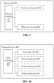
- An optional composition structure of the remote UE 800, as shown in FIG. 9 includes a second sending unit 801.
- the second sending unit 801 is configured to send first information to a relay UE, such that the relay UE sends a first connection establishment request message to a network device.
- the second sending unit 801 is further configured to send a connection establishment cause value to the remote UE.
- connection establishment cause value may be sent to an NAS entity of the relay UE by the remote UE.
- connection establishment cause value may be sent to an AS entity of the UE by the remote UE.
- the remote UE 800 further includes a fourth receiving unit 802, configured to receive connection establishment success indication information sent by the relay UE.
- connection establishment success indication information is configured to indicate that the relay UE is successfully connected to the network device.
- the second sending unit is configured to send third information to the relay UE, and the third information is sent to the network device through the relay UE.
- the fourth receiving unit 802 is configured to receive fourth information sent by the relay UE, and the fourth information is sent to the relay UE by the network device.
- the remote UE 800 further includes a fifth receiving unit 803.
- the fifth receiving unit 803 is configured to receive connection establishment failure indication information sent by the relay UE.
- connection establishment failure indication information is configured to indicate the cause of the connection failure between the remote UE and the network device.
- connection establishment cause value corresponds to a relay manner of the relay UE.
- the first information includes an RRC message or indication information that triggers the relay UE to establish an RRC connection with the network device.
- the relay UE adopts a manner of a layer 2 relay to establish the connection with the network device; and/or, the remote UE establishes a connection with the relay UE through an SL.
- Optional composition structure of the network device 900 includes a sixth receiving unit 901.
- the sixth receiving unit 901 is configured to receive a first connection establishment request message sent by a relay UE.
- the first connection establishment request message carries a connection establishment cause value, and the first connection establishment request message is configured to request the establishment of a connection between the relay UE and the network device.
- connection establishment cause value is sent to an AS entity of the relay UE by the remote UE.
- connection establishment cause value is determined by the AS entity of the relay UE according to a protocol.
- connection establishment cause value is sent to an NAS entity of the relay UE by the remote UE, and then sent to the AS entity of the relay UE by the NAS entity.
- connection establishment cause value is determined by the NAS entity of the relay UE according to the protocol, and then sent to the AS entity of the relay UE by the NAS entity.
- the network device 900 further includes a processing unit 902.
- the processing unit 902 is configured to determine whether to establish the connection between the network device and the relay UE based on the first connection establishment request message.
- the network device 900 further includes a third sending unit 903.
- the third sending unit 903 is configured to send connection establishment failure indication information to the relay UE.
- connection establishment success indication information is configured to indicate that the relay UE is successfully connected with the network device.
- the sixth receiving unit 901 is further configured to receive first indication information sent by the relay UE.
- the first indication information is configured to indicate related information of an SL between the relay UE and the remote UE.
- the network device 900 further includes a fourth sending unit 904.
- the fourth sending unit 904 is configured to send first configuration information to the relay UE.
- the first configuration information is used for the relay UE and the remote UE to transmit information.
- the sixth receiving unit 901 is configured to receive the first information sent by the relay UE; or, receive second information which is sent by the relay UE based on the first information.
- the first information is sent to the relay UE by the remote UE.
- the second information includes an RRC message.
- the sixth receiving unit is further configured to receive third information sent by the relay UE, and the third information is sent to the relay UE by the remote UE.
- the third sending unit is further configured to send fourth information to the relay UE, and the fourth information is sent to the remote UE through the relay UE.
- the third information includes an RRC message; and/or, the fourth information includes an RRC message.
- the network device 900 further includes a fifth sending unit 905.
- the fifth sending unit 905 is configured to send connection establishment failure indication information to the relay UE.
- connection establishment failure indication information is configured to indicate the cause of the connection failure between the remote UE and the network device.
- connection establishment cause value corresponds to a relay manner of the relay UE.
- the relay UE adopts a manner of a layer 2 relay to establish the connection with the network device; and/or, the remote UE establishes a connection with the relay UE through the SL.
- the embodiments of the disclosure also provide a relay UE, which includes a processor and a memory.
- the memory is configured to store a computer program runnable on the processor.
- the processor is configured to run the computer program to perform the steps of the method for establishing relay connection performed by the above relay UE.
- the embodiments of the disclosure also provide a remote UE, which includes a processor and a memory.
- the memory is configured to store a computer program runnable on the processor.
- the processor is configured to run the computer program to perform the steps of the method for establishing relay connection performed by the above remote UE.
- the embodiments of the disclosure also provide a network device, which includes a processor and a memory.
- the memory is configured to store a computer program runnable on the processor.
- the processor is configured to run the computer program to perform the steps of the method for establishing relay connection performed by the above network device.
- the embodiments of the disclosure also provide a chip, which includes a processor, configured to call and run a computer program from a memory to cause a relay UE installed with the chip to perform the method for establishing relay connection performed by the above sending device.
- the embodiments of the disclosure also provide a chip, which includes a processor, configured to call and run a computer program from a memory to cause a remote UE installed with the chip to perform the method for establishing relay connection performed by the above receiving device.
- the embodiments of the disclosure also provide a chip, which includes a processor, configured to call and run a computer program from a memory to cause a remote UE installed with the chip to perform the method for establishing relay connection performed by the above network device.
- the embodiments of the disclosure also provide a storage medium, storing an executable program.
- the executable program implements the method for establishing relay connection performed by the above relay UE when being executed by a processor.
- the embodiments of the disclosure also provide a storage medium, storing an executable program.
- the executable program implements the method for establishing relay connection performed by the above remote UE when being executed by a processor.
- the embodiments of the disclosure also provide a storage medium, storing an executable program.
- the executable program implements the method for establishing relay connection performed by the above network device when being executed by a processor.
- the embodiments of the disclosure also provide a computer program product, which includes a computer program instruction.
- the computer program instruction causes a computer to perform the method for establishing relay connection performed by the above relay UE.
- the embodiments of the disclosure also provide a computer program product, which includes a computer program instruction.
- the computer program instruction causes a computer to perform the method for establishing relay connection performed by the above remote UE.
- the embodiments of the disclosure also provide a computer program product, which includes a computer program instruction.
- the computer program instruction causes a computer to perform the method for establishing relay connection performed by the above network device.
- the embodiments of the disclosure also provide a computer program.
- the computer program causes a computer to perform the method for establishing relay connection performed by the above relay UE.
- the embodiments of the disclosure also provide a computer program.
- the computer program causes a computer to perform the method for establishing relay connection performed by the above remote UE.
- the embodiments of the disclosure also provide a computer program.
- the computer program causes a computer to perform the method for establishing relay connection performed by the above network device.
- FIG. 11 is a schematic diagram of hardware composition structure of an electronic device (a relay UE, a remote UE or a network device) according to an embodiment of the disclosure.
- the electronic device 700 includes at least one processor 701, a memory 702, and at least one network interface 704.
- Various components of the electronic device 700 are coupled together through a bus system 705. It is to be understood that the bus system 705 is configured to implement connection and communication between these components.
- the bus system 705 further includes a power bus, a control bus and a state signal bus. However, for clarity of illustration, the various buses are labeled as the bus system 705 in FIG. 11 .
- the memory 702 may be a volatile memory or a non-volatile memory, or may include both the volatile and non-volatile memories.
- the non-volatile memory may be a Read-Only Memory (ROM), a Programmable ROM (PROM), an Erasable PROM (EPROM), an Electrically EPROM (EEPROM), a Ferromagnetic Random Access Memory (FRAM), a Flash Memory, a magnetic surface memory, an optical disk or a Compact Disc Read-Only Memory (CD-ROM); and the magnetic surface memory may be a magnetic disk memory or a magnetic tape memory.
- the volatile memory may be a RAM that acts as an external cache.
- RAMs in various forms may be adopted, such as a Static RAM (SRAM), a Dynamic RAM (DRAM), a Synchronous DRAM (SDRAM), a Double Data Rate SDRAM (DDRSDRAM), an Enhanced SDRAM (ESDRAM), a Synchlink DRAM (SLDRAM) and a Direct Rambus RAM (DRRAM).
- SRAM Static RAM
- DRAM Dynamic RAM
- SDRAM Synchronous DRAM
- DDRSDRAM Double Data Rate SDRAM
- ESDRAM Enhanced SDRAM
- SLDRAM Synchlink DRAM
- DRRAM Direct Rambus RAM
- the memory 702 in the embodiments of the disclosure is configured to store various types of data to support operation of the electronic device 700.
- Examples of such data include: any computer application operated on the electronic device 700, such as an application program 7022.
- a program for implementing the method in the embodiments of the disclosure may be included in the application program 7022.
- the method disclosed in the embodiments of the disclosure may be applied to the processor 701, or may be implemented by the processor 701.
- the processor 701 may be an integrated circuit chip with signal processing capability. During implementation, the steps of the above method may be completed by hardware integrated logic circuits in the processor 701 or instructions in the form of software.
- the above processor 701 may be a general-purpose processor, a Digital Signal Processor (DSP), or other programmable logic devices, discrete gate or transistor logic devices, discrete hardware components, etc.
- DSP Digital Signal Processor
- the processor 701 may implement or perform various methods, steps, and logical block diagrams disclosed in the embodiments of the disclosure.
- the general-purpose processor may be a microprocessor or any conventional processor, etc.
- the steps may be directly implemented by a hardware processor, or may be performed by a combination of hardware and software modules in the decoding processor.
- the software module may be located in a storage medium.
- the storage medium is located in the memory 702, and the processor 701 reads information in the memory 702 and completes the steps of the method in combination with hardware.
- the electronic device 700 may be implemented by one or more Application Specific Integrated Circuits (ASICs), DSPs, Programmable Logic Devices (PLDs), Complex Programmable Logic Devices (CPLDs), Field-Programmable Gate Arrays (FPGAs), general-purpose processors, controllers, MCUs, MPUs, or other electronic elements for performing the above methods.
- ASICs Application Specific Integrated Circuits
- DSPs Digital Signal processors
- PLDs Programmable Logic Devices
- CPLDs Complex Programmable Logic Devices
- FPGAs Field-Programmable Gate Arrays
- controllers MCUs, MPUs, or other electronic elements for performing the above methods.
- each flow and/or block in the flowcharts and/or the block diagrams and a combination of the flows and/or the blocks in the flowcharts and/or the block diagrams may be implemented by computer program instructions.
- These computer program instructions may be provided for a general-purpose computer, a dedicated computer, an embedded processor or processors of other programmable data processing devices to generate a machine, so that an apparatus for achieving functions designated in one or more flows of the flowcharts and/or one or more blocks of the block diagrams is generated via instructions executed by the computers or the processors of the other programmable data processing devices.
- These computer program instructions may also be stored in a computer readable memory capable of guiding the computers or the other programmable data processing devices to work in a specific manner, so that a manufactured product including an instruction apparatus is generated via the instructions stored in the computer readable memory, and the instruction apparatus achieves the functions designated in one or more flows of the flowcharts and/or one or more blocks of the block diagrams.
- These computer program instructions may also be loaded to the computers or the other programmable data processing devices, so that processing implemented by the computers is generated by executing a series of operation steps on the computers or the other programmable devices, and therefore the instructions executed on the computers or the other programmable devices provide a step of achieving the functions designated in one or more flows of the flowcharts and/or one or more blocks of the block diagrams.
- system and “network” herein are usually interchangeable herein.
- term “and/or” is only an association relationship describing associated objects, and represents that three relationships may exist.
- a and/or B may represent three conditions: i.e., existence of only A, existence of both A and B, and existence of only B.
- character “j" herein usually represents that previous and next associated objects form an "or" relationship.
Landscapes
- Engineering & Computer Science (AREA)
- Computer Networks & Wireless Communication (AREA)
- Signal Processing (AREA)
- Mobile Radio Communication Systems (AREA)
Abstract
Description
- The disclosure relates to the technical field of Sidelink (SL) transmission, in particular to a relay connection establishment method, an electronic device, and a storage medium.
- In a New Radio-Vehicle to Everything (NR-V2X) system, a process of establishing a connection from a User Equipment (UE) to a network device based on a
layer 2 relay has not yet been specified. - Embodiments of the disclosure provide a method for establishing relay connection, an electronic device, and a storage medium, and specify a process of establishing a connection from a UE to a network device based on a
layer 2 relay. - In a first aspect, the embodiments of the disclosure provide a method for establishing relay connection, which may include that: a relay UE sends a first connection establishment request message to a network device.
- The first connection establishment request message carries a connection establishment cause value, and the first connection establishment request message is configured to request the establishment of a connection between the relay UE and the network device.
- In a second aspect, the embodiments of the disclosure provide a method for establishing relay connection, which may include that: a remote UE sends first information to a relay UE, so that the relay UE sends a first connection establishment request message to a network device.
- In a third aspect, the embodiments of the disclosure provide a method for establishing relay connection, which may include that: a network device receives a first connection establishment request message sent by a relay UE, the first connection establishment request message carries a connection establishment cause value, and the first connection establishment request message is configured to request the establishment of a connection between the relay UE and the network device.
- In a fourth aspect, the embodiments of the disclosure provide a relay UE, which may include a first sending unit.
- The first sending unit is configured to send a first connection establishment request message to a network device.
- The first connection establishment request message carries a connection establishment cause value, and the first connection establishment request message is configured to request the establishment of a connection between the relay UE and the network device.
- In a fifth aspect, the embodiments of the disclosure provide a remote UE, which may include a second sending unit.
- The second sending unit is configured to send first information to a relay UE, such that the relay UE sends a first connection establishment request message to a network device.
- In a sixth aspect, the embodiments of the disclosure provide a network device, which may include a sixth receiving unit.
- The sixth receiving unit is configured to receive a first connection establishment request message sent by a relay UE, the first connection establishment request message carries a connection establishment cause value, and the first connection establishment request message is configured to request the establishment of a connection between the relay UE and the network device.
- In a seventh aspect, the embodiments of the disclosure provide a relay UE, which may include a processor and a memory. The memory is configured to store a computer program runnable on the processor. The processor is configured to run the computer program to perform the steps of the method for establishing relay connection performed by the above relay UE.
- In an eighth aspect, the embodiments of the disclosure provide a remote UE, which may include a processor and a memory. The memory is configured to store a computer program runnable on the processor. The processor is configured to run the computer program to perform the steps of the method for establishing relay connection performed by the above remote UE.
- In a ninth aspect, the embodiments of the disclosure provide a network device, which may include a processor and a memory. The memory is configured to store a computer program runnable on the processor. The processor is configured to run the computer program to perform the steps of the method for establishing relay connection performed by the above network device.
- In a tenth aspect, the embodiments of the disclosure provide a chip, which includes a processor, configured to call and run a computer program from a memory to cause a relay UE installed with the chip to perform the method for establishing relay connection performed by the above sending device.
- In an eleventh aspect, the embodiments of the disclosure provide a chip, which includes a processor, configured to call and run a computer program from a memory to cause a remote UE installed with the chip to perform the method for establishing relay connection performed by the above receiving device.
- In a twelfth aspect, the embodiments of the disclosure provide a chip, which includes a processor, configured to call and run a computer program from a memory to cause a network device installed with the chip to perform the method for establishing relay connection performed by the above receiving device.
- In a thirteenth aspect, the embodiments of the disclosure provide a storage medium, storing an executable program. The executable program implements the method for establishing relay connection performed by the above relay UE when being executed by a processor.
- In a fourteenth aspect, the embodiments of the disclosure provide a storage medium, storing an executable program. The executable program implements the method for establishing relay connection performed by the above remote UE when being executed by a processor.
- In a fifteenth aspect, the embodiments of the disclosure provide a storage medium, storing an executable program. The executable program implements the method for establishing relay connection performed by the above network device when being executed by a processor.
- In a sixteenth aspect, the embodiments of the disclosure provide a computer program product, which may include a computer program instruction. The computer program instruction causes a computer to perform the method for establishing relay connection performed by the above remote UE.
- In a seventeenth aspect, the embodiments of the disclosure provide a computer program product, which may include a computer program instruction. The computer program instruction causes a computer to perform the method for establishing relay connection performed by the above relay UE.
- In an eighteenth aspect, the embodiments of the disclosure provide a computer program product, which may include a computer program instruction. The computer program instruction causes a computer to perform the method for establishing relay connection performed by the above network device.
- In a nineteenth aspect, the embodiments of the disclosure provide a computer program. The computer program causes a computer to perform the method for establishing relay connection performed by the above relay UE.
- In a twentieth aspect, the embodiments of the disclosure provide a computer program. The computer program causes a computer to perform the method for establishing relay connection performed by the above remote UE.
- In a twenty-first aspect, the embodiments of the disclosure provide a computer program. The computer program causes a computer to perform the method for establishing relay connection performed by the above network device.
-
-
FIG. 1 is a schematic flow diagram of selecting a transmission resource in a first mode according to the disclosure. -
FIG. 2 is a schematic flow diagram of selecting a transmission resource in a second mode according to the disclosure. -
FIG. 3 is a schematic diagram of a connection establishment flow of a relay network according to an embodiment of the disclosure. -
FIG. 4 is a schematic diagram of an optional processing flow of a relay connection establishment method according to an embodiment of the disclosure. -
FIG. 5 is a schematic diagram of another optional processing flow of a relay connection establishment method according to an embodiment of the disclosure. -
FIG. 6 is a schematic diagram of yet another optional processing flow of a relay connection establishment method according to an embodiment of the disclosure. -
FIG. 7 is a schematic diagram of a detailed processing flow of relay connection establishment according to an embodiment of the disclosure. -
FIG. 8 is a schematic diagram of an optional composition structure of a relay UE according to an embodiment of the disclosure. -
FIG. 9 is a schematic diagram of an optional composition structure of a remote UE according to an embodiment of the disclosure. -
FIG. 10 is a schematic diagram of an optional composition structure of a network device according to an embodiment of the disclosure. -
FIG. 11 is a schematic diagram of a hardware composition structure of an electronic device according to an embodiment of the disclosure. - In order to provide a more detailed understanding of the features and technical contents of the embodiments of the disclosure, the implementation of the embodiments of the disclosure will be described in detail below in combination with the drawings, and the accompanying drawings are for illustrative purposes only and are not intended to limit the embodiments of the disclosure.
- Before the description of the embodiments of the disclosure, the relevant contents are briefly described.
- Device to Device (D2D) communication is an SL-based transmission technology. Different from a manner in a conventional cellular system of receiving or sending communication data through a network device, higher spectral efficiency and lower transmission time delay can be implemented. An Internet of vehicles system adopts a manner of D2D communication (that is, a manner of direct D2D communication). In an NR system, for D2D communication, a Third Generation Partnership Project (3GPP) defines two modes of transmission: a first mode (also called mode A) and a second mode (also called mode B). The first mode is that the network device allocates a transmission resource for a UE, and the second mode is that the UE selects the transmission resource independently.
- For the first mode: as shown in
FIG. 1 , the transmission resource of the UE is allocated by the network device, and the UE sends data on the SL according to the resource allocated by the network device. The network device may allocate the resource for a single transmission to the UE, or may allocate a semi-static transmission resource to the UE. - For the second mode: as shown in
FIG. 2 , the UE selects one resource from a resource pool for data transmission. - The UE may acquire the transmission resource by using either the first mode or the second mode, or both simultaneously. The acquisition of the transmission resource may be indicated through SL grant. As an example, the SL grant indicates time-frequency locations of corresponding Physical Sidelink Control Channel (PSCCH) resource and Physical Sidelink Shared Channel (PSSCH) resource.
- In NR V2X, the UE may independently initiate Hybrid Automatic Repeat Request (HARQ) retransmission. As an example, feedback-based HARQ retransmission may be introduced in both unicast communication and multicast communication in NR V2X.
- In 3GPP Rel 12/13, for a Proximity based Service (ProSe), it can be implemented that the UE sends and/or receives data discontinuously on the SL by configuring the location of the resource pool in a time domain, for example, the resource pool is discontinuous in the time domain, thereby achieving the effect of power saving.
- In R14/15, the Internet of vehicles system has requirements for a vehiclevehicle communication scenario, which is mainly for relatively high-speed moving vehiclevehicle and vehicle-person communication services.
- In a V2X system, an on-board system has continuous power supply, so that data transmission delay is the main problem to be solved. Therefore, continuous transmission and reception of the UE is required in system design.
- In R14, a scenario that a wearable device (FeD2D) accesses a network through a mobile phone is studied, especially for scenarios with low mobile speed and low power access. For FeD2D, the network device may configure Discontinuous Reception (DRX) parameters of a remote terminal through a relay terminal.
- A connection establishment process of the UE is briefly described below.
- Before the UE initiates a call, access control is performed first. From the perspective of an executor, the access control may be classified into two types: the first is performed by the UE itself, which is collectively referred to as Unified Access Control (UAC) in the NR system, and the second is performed by the network device according to a "Radio Resource Control (RRC) establishment cause" in an RRC setup request (SetupRequest) message. The key of the second access control is that a Non Access Stratum (NAS) of the UE may obtain the "RRC establishment cause" according to the mapping of an access identifier and an access category while initiating the call. The "RRC establishment cause" is encoded in the RRCSetupRequest message by the RRC layer and sent to the network device. How the network device performs access control according to the "RRC establishment cause" is an internal algorithm of the network device, which is implemented by the network device. If the network device accepts the RRCSetupRequest message initiated by the UE, the network device sends the RRCSetup message for response, otherwise the network device sends an RRCReject (RRC reject) message for rejection.
- A UE-to-network relay function based on a
layer 3 relay is introduced in R13, that is, the remote UE accesses the network through the relay UE. The relay UE performs the relay function of an Internet Protocol (IP) layer, and transmits data between the remote UE and the network device. The remote UE is connected with the relay UE through the SL. A connection establishment flow of the relay network may be shown inFIG. 3 : instep 5, the relay UE reports an Identification (ID) and IP information of the remote UE to the network device, the network device learns the association between the relay UE and the remote UE according to the reported message, so that corresponding bearer/session management and configuration is performed, thereby enabling the remote UE to be connected to the network through the relay UE. - For a UE-to-network relay function based on the
layer 2 relay, the remote UE accesses the network through the relay UE. The relay UE performs the relay function of an adaption layer, and transmits data between the remote UE and the network device. The remote UE is connected with the relay UE through the SL. The adaption layer is above a Radio Link Control (RLC) layer and below a Packet Data Convergence Protocol (PDCP) layer. However, the UE-to-network connection establishment process based on thelayer 2 relay has not been specified in related technologies. - It is to be understood that the sequence numbers of the implementation processes do not mean execution sequences in various embodiments of the disclosure. The execution sequences of the processes should be determined according to functions and internal logics of the processes, and should not be construed as any limitation to the implementation processes of the embodiments of the disclosure.
- The embodiments of the disclosure provide a method for establishing relay connection, which specifies a connection establishment process in a
layer 2 relay. - An optional processing flow of a relay connection establishment method according to an embodiment of the disclosure, as shown in
FIG. 4 , includes the step S201. - At step S201, a relay UE sends a first connection establishment request message to a network device, the first connection establishment request message carries a connection establishment cause value, and the first connection establishment request message is configured to request the establishment of a connection between the relay UE and the network device.
- In some embodiments, if the relay UE needs to act as the relay of uplink transmission for the remote UE, or the relay UE needs to act as the relay of downlink transmission for the network device, the relay UE needs to be in an RRC connected state. As an example, the relay UE sends an RRCSetupRequest message to the network device.
- In some embodiments, the connection establishment cause value (establishmentCause) may be "relay", namely "establishmentCause=ralay", which represents that the connection requested to be established is used for the relay that performs the transmission. In the embodiments of the disclosure, the specific form and content of the connection establishment cause value are not limited.
- In some embodiments, the connection establishment cause value may be sent to the relay UE by the remote UE. As an example, the connection establishment cause value may be sent to an Access Stratum (AS) entity of the relay UE by the remote UE. Or, the connection establishment cause value is determined by the AS entity of the relay UE according to a protocol. As an example, the connection establishment cause value corresponds to a relay manner of the relay UE, for example, a relay based on
layer 2 corresponds to a connection establishment cause value of 1, and a relay based onlayer 3 corresponds to a connection establishment cause value of 2. Or, the connection establishment cause value is sent to an NAS entity of the relay UE by the remote UE, and then sent to the AS entity of the relay UE by the NAS entity. Or, the connection establishment cause value is determined by the NAS entity of the relay UE according to the protocol, and then sent to the AS entity of the relay UE by the NAS entity. - In some embodiments, the method may further include step S202.
- At step S202, the relay UE receives first information sent by the remote UE.
- In some embodiments, the first information may be an RRC message. As an example, the remote UE sends the RRC message to the relay UE, and the RRC message may carry the connection establishment cause value.
- In some embodiments, the first information may be indication information that triggers the relay UE to establish an RRC connection with the network device, and the indication information that triggers the relay UE to establish the RRC connection with the network device may carry the connection establishment cause value. As an example, the remote UE sends the indication information to the relay UE, and the indication information is configured to instruct the relay UE to establish the RRC connection with the network device. The relay UE, after receiving the indication information, sends the first connection establishment request message to the network device. In this scenario, the relay UE needs to fill the connection establishment cause value in the first connection establishment request message.
- In some embodiments, the method may further include step S203.
- At step S203, a prose layer entity or a PC5-RRC layer entity of the relay UE sends a notification message to the NAS entity. The notification message is configured to notify the NAS entity to establish an NAS connection.
- In some embodiments, the NAS entity of the relay UE passes the establishmentCause value to the AS entity of the relay UE and triggers the AS entity of the relay UE to establish the RRC connection. The AS entity of the relay UE fills in the RRC connection establishment request message.
- In some embodiments, the method may further include step S204.
- At step S204, the relay UE receives connection establishment success indication information sent by the network device.
- In some embodiments, the connection establishment success indication information is configured to indicate that the relay UE is successfully connected with the network device.
- In some embodiments, the method may further include step S205.
- At step S205, the relay UE sends the connection establishment success indication information to the remote UE.
- In some embodiments, if the relay UE is successfully connected with the network device, the method may further include step S206.
- At step S206, the relay UE sends first indication information to the network device. The first indication information is configured to indicate related information of an SL between the relay UE and the remote UE.
- In some embodiments, the related information of the SL between the relay UE and the remote UE may include at least one of the following:
- Quality of Service (QoS) parameters and QoS profile(s) related to NR sidelink communication, a sidelink radio link failure or sidelink RRC reconfiguration failure has been detected, the sidelink UE capability information of the associated peer UE for unicast communication, or the RLC mode information of the sidelink data radio bearer(s) received from the associated peer UE for unicast communication.
- In some embodiments, the method may further include step S207.
- At step S207, the relay UE receives first configuration information sent by the network device. The first configuration information is used for the relay UE and the remote UE to transmit information.
- In some embodiments, the first configuration information may be configuration information used for transmission between the relay UE and the remote UE. As an example, the first configuration information may be a time-frequency resource used for the transmission performed by the relay UE and the remote UE.
- In some embodiments, if the relay UE is successfully connected with the network device, the method may further include step S208.
- At step S208, the relay UE forwards at least one of the first information, second information, third information, or fourth information to the network device.
- In some embodiments, the relay UE receives the first information sent by the remote UE, and the relay UE forwards the first information to the network device.
- In some embodiments, the relay UE sends the second information to the network device, and the second information is obtained by mapping the first information through an adaption layer of the relay UE.
- In some embodiments, the relay UE receives the third information sent by the remote UE, and the relay UE forwards the third information to the network device.
- In some embodiments, the relay UE receives the fourth information sent by the network device, and the relay UE forwards the fourth information to the remote UE.
- In some embodiments, both the third information and the fourth information may be RRC messages.
- In some embodiments, the relay UE transmits the third information and/or the fourth information between the network device and the remote UE based on the
layer 2 relay and the SL. - In some embodiments, the method may further include step S209.
- At step S209, the relay UE receives connection establishment failure indication information sent by the network device.
- In some embodiments, the connection establishment failure indication information is configured to indicate the cause of the connection failure between the relay UE and the network device. As an example, the connection establishment failure indication information may also be referred to as connection establishment rejection information.
- In some embodiments, the cause of the connection failure between the relay UE and the network device may be that the priority of the relay UE is low, the network device does not support the relay, or the number of relay UEs that have established a relay connection with the network device reaches a threshold value.
- In some embodiments, the method may further include step S210.
- At step S210, the relay UE sends the connection establishment failure indication information to the remote UE.
- In some embodiments, the relay UE sends the connection establishment failure indication information to the remote UE for informing the remote UE that the relay connection establishment fails.
- In the embodiments of the disclosure, the relay UE establishes the connection with the network device by using the
layer 2 relay. The remote UE establishes the connection with the relay UE through the SL. - Another optional processing flow of a relay connection establishment method according to an embodiment of the disclosure, as shown in
FIG. 5 , includes the following steps. - At step S301, a remote UE sends first information to a relay UE, so that the relay UE sends a first connection establishment request message to a network device.
- In some embodiments, the first information may be an RRC message. As an example, the remote UE sends the RRC message to the relay UE, and the RRC message carries a connection establishment cause value.
- In some embodiments, the first information may be indication information that triggers the relay UE to establish an RRC connection with the network device. As an example, the remote UE sends the indication information to the relay UE, the indication information is configured to instruct the relay UE to establish the RRC connection with the network device, and the indication information may carry the connection establishment cause value. The relay UE, after receiving the indication information, sends the first connection establishment request message to the network device.
- In some embodiments, the connection establishment cause value (establishmentCause) may be "relay", namely "establishmentCause=ralay", which represents that the connection requested to be established is used for the relay that performs the transmission. In the embodiments of the disclosure, the specific form and content of the connection establishment cause value are not limited.
- In some embodiments, the connection establishment cause value may be sent to the relay UE by the remote UE. As an example, the connection establishment cause value may be sent to an AS entity or an NAS entity of the relay UE by the remote UE. As an example, the connection establishment cause value corresponds to a relay manner of the relay UE, for example, a relay based on
layer 2 corresponds to a connection establishment cause value of 1, and a relay based onlayer 3 corresponds to a connection establishment cause value of 2. Or, the connection establishment cause value may be sent to the NAS entity of the relay UE by the remote UE, and then sent to the AS entity of the relay UE by the NAS entity. Or, the connection establishment cause value is determined by the NAS entity of the relay UE according to the protocol, and then sent to the AS entity of the relay UE by the NAS entity. - In some embodiments, the method may further include step S302.
- At step S302, the remote UE sends the connection establishment cause value to the relay UE.
- In some embodiments, the method may further include step S303.
- At step S303, the remote UE receives connection establishment success indication information sent by the relay UE.
- The connection establishment success indication information is configured to indicate that the relay UE is successfully connected to the network device.
- In some embodiments, if the relay UE is successfully connected to the network device, the method may further include the following operation.
- At step S304, the remote UE sends third information to the relay UE, and the third information is sent to the network device through the relay UE.
- In some embodiments, if the relay UE is successfully connected to the network device, the method may further include the following operation.
- At S305, the remote UE receives fourth information sent by the relay UE, and the fourth information is sent to the relay UE by the network device.
- In steps S304 to S305, the relay UE transmits the third information and/or the fourth information between the network device and the remote UE based on a
layer 2 relay and an SL. - In some embodiments, the method may further include the following operation.
- At step S306, the remote UE receives connection establishment failure indication information sent by the relay UE.
- In some embodiments, the connection establishment failure indication information is configured to indicate the cause of the connection failure between the remote UE and the network device.
- In the embodiments of the disclosure, the relay UE establishes the connection with the network device by using the
layer 2 relay. The remote UE establishes the connection with the relay UE through the SL. - Another optional processing flow of a relay connection establishment method according to an embodiment of the disclosure, as shown in
FIG. 6 , includes the following step. - At step S401, a network device receives a first connection establishment request message sent by a relay UE, the first connection establishment request message carries a connection establishment cause value, and the first connection establishment request message is configured to request the establishment of a connection between the relay UE and the network device.
- In some embodiments, if the relay UE needs to act as the relay of uplink transmission for the remote UE, or the relay UE needs to act as the relay of downlink transmission for the network device, the relay UE needs to be in an RRC connected state. As an example, the relay UE sends an RRCSetupRequest message to the network device.
- In some embodiments, the connection establishment cause value (establishmentCause) may be "relay", namely "establishmentCause=ralay", which represents that the connection requested to be established is used for the relay that performs the transmission. In the embodiments of the disclosure, the specific form and content of the connection establishment cause value are not limited.
- In some embodiments, the connection establishment cause value may be sent to the relay UE by the remote UE. As an example, the connection establishment cause value may be sent to an AS entity of the relay UE by the remote UE. Or, the connection establishment cause value may be determined by the AS entity of the relay UE according to a protocol. As an example, the connection establishment cause value corresponds to a relay manner of the relay UE, for example, a relay based on
layer 2 corresponds to a connection establishment cause value of 1, and a relay based onlayer 3 corresponds to a connection establishment cause value of 2. Or, the connection establishment cause value may be sent to an NAS entity of the relay UE by the remote UE, and then sent to the AS entity of the relay UE by the NAS entity. Or, the connection establishment cause value is determined by the NAS entity of the relay UE according to the protocol, and then sent to the AS entity of the relay UE by the NAS entity. - In some embodiments, the method may further include the following operation.
- At step S402, the network device receives first information sent by the relay UE. Or, the network device receives second information sent by the relay UE based on the first information.
- In some embodiments, the first information is sent to the relay UE by the remote UE.
- In some embodiments, the first information may be an RRC message. As an example, the remote UE sends the RRC message to the relay UE, and the RRC message carries the connection establishment cause value.
- In some embodiments, the first information may be indication information that triggers the relay UE to establish an RRC connection with the network device. As an example, the remote UE sends the indication information to the relay UE, the indication information is configured to instruct the relay UE to establish the RRC connection with the network device, and the indication information may carry the connection establishment cause value. The relay UE, after receiving the indication information, sends the first connection establishment request message to the network device.
- In some embodiments, the method may further include the following operation.
- At step S403, the network device determines whether to establish the connection between the network device and the relay UE based on the first connection establishment request message.
- In some embodiments, the network device may determine whether to establish a connection between the network device and the relay UE according to the connection establishment cause value carried in the first connection establishment request message. As an example, if the connection establishment cause value is "relay" and the network device supports the relay, the network device establishes the connection between the network device and the relay UE. As an example, if the connection establishment cause value is "relay" and the network device does not support the relay, the network device does not establish the connection between the network device and the relay UE.
- In some embodiments, if the network device determines to establish the connection between the network device and the relay UE in step S403, the method may further include the following operation.
- At step S404, the network device sends connection establishment success indication information to the relay UE.
- In some embodiments, the connection establishment success indication information is configured to indicate that the relay UE is successfully connected to the network device.
- In some embodiments, the method may further include the following operation.
- At step S405, the network device receives first indication information sent by the relay UE. The first indication information is configured to indicate related information of an SL between the relay UE and the remote UE.
- In some embodiments, the related information of the SL between the relay UE and the remote UE may include at least one of the following:
- QoS parameters and QoS profile(s) related to NR sidelink communication, a sidelink radio link failure or sidelink RRC reconfiguration failure has been detected, the sidelink UE capability information of the associated peer UE for unicast communication, or the RLC mode information of the sidelink data radio bearer(s) received from the associated peer UE for unicast communication.
- In some embodiments, the method may further include the following operation.
- At step S406, the network device sends first configuration information to the relay UE, and the first configuration information is used for the relay UE and the remote UE to transmit information.
- In some embodiments, the first configuration information may be configuration information used for transmission between the relay UE and the remote UE. As an example, the first configuration information may be a time-frequency resource used for the transmission performed by the relay UE and the remote UE.
- In some embodiments, if the relay UE is successfully connected to the network device, the method may further include the following operation.
- At step S407, the network device receives the first information forwarded by the relay UE; or, the network device receives the second information obtained by the relay UE based on the first information; or, the network device receives third information sent by the relay UE, and the third information is sent to the relay UE by the remote UE.
- In some embodiments, the first information may be sent to the relay UE by the remote UE before performing step S401. The first information may also be sent to the relay UE by the remote UE after the relay UE establishes the connection with the network device.
- In some embodiments, the third information includes an RRC message.
- In some embodiments, if the relay UE is successfully connected with the network device, the method may further include the following operation.
- At step S408, the network device sends fourth information to the relay UE, and the fourth information is sent to the remote UE through the relay UE.
- In some embodiments, the fourth information includes an RRC message.
- In steps S407 and S408, the relay UE transmits at least one of the first information, the second information, the third information, or the fourth information between the network device and the remote UE based on a
layer 2 relay and an SL. - In some embodiments, if the network device determines to establish the connection between the network device and the relay UE in step S403, the method may further include the following operation.
- At S409, the network device sends connection establishment failure indication information to the relay UE.
- In some embodiments, the connection establishment failure indication information is configured to indicate the cause of the connection failure between the remote UE and the network device. As an example, the connection establishment failure indication information may also be referred to as connection establishment rejection information.
- In the embodiments of the disclosure, the relay UE establishes the connection with the network device by using the
layer 2 relay. The remote UE establishes the connection with the relay UE through the SL. - In embodiments of the disclosure, a detailed processing flow of relay connection establishment, as shown in
FIG. 7 , includes the following operations. - At step S501, a remote UE sends first information to a relay UE.
- In some embodiments, the description of the first information is the same as the description of the first indication information in the above embodiments and will not be elaborated here.
- At step S502, the relay UE determines an RRC connection establishment request message.
- In some embodiments, the relay UE fills a connection establishment cause value in the RRC connection establishment request message.
- In some embodiments, the connection establishment cause value may be sent to the relay UE by the remote UE. As an example, the connection establishment cause value may be sent to an AS entity of the relay UE by the remote UE. Or, the connection establishment cause value may be determined by the AS entity of the relay UE according to a protocol. As an example, the connection establishment cause value corresponds to a relay manner of the relay UE, for example, a relay based on
layer 2 corresponds to a connection establishment cause value of 1, and a relay based onlayer 3 corresponds to a connection establishment cause value of 2. Or, the connection establishment cause value may be sent to an NAS entity of the relay UE by the remote UE, and then sent to the AS entity of the relay UE by the NAS entity. Or, the connection establishment cause value is determined by the NAS entity of the relay UE according to the protocol, and then sent to the AS entity of the relay UE by the NAS entity. - At step S503, the relay UE sends the first connection establishment request message to a network device.
- At step S504, the network device sends connection establishment success information or connection establishment rejection information to a UE.
- At step S505, the relay UE sends the connection establishment success information or the connection establishment rejection information to the remote UE.
- At step S506, after the relay UE receives the connection establishment success information, the relay UE sends first indication information to the network device. The first indication information is configured to indicate related information of an SL between the relay UE and the remote UE.
- In some embodiments, the related information of the SL between the relay UE and the remote UE may include at least one of the following:
- QoS parameters and QoS profile(s) related to NR sidelink communication, a sidelink radio link failure or sidelink RRC reconfiguration failure has been detected, the sidelink UE capability information of the associated peer UE for unicast communication, or the RLC mode information of the sidelink data radio bearer(s) received from the associated peer UE for unicast communication.
- At step S507, the network device receives first configuration information sent to the relay UE, and the first configuration information is used for the relay UE and the remote UE to transmit information.
- In some embodiments, the first configuration information may be configuration information used for transmission between the relay UE and the remote UE. As an example, the first configuration information may be a time-frequency resource used for the transmission performed by the relay UE and the remote UE.
- At S508, the relay UE is in a connected state after receiving the connection establishment success information. The relay UE may perform at least one of the following information forwarding operation that: the relay UE forwards the first information to the network device for the remote UE; the relay UE sends second information to the network device based on the first information; the remote UE sends third information to the relay UE, and the relay UE sends the third information to the network device; and the network device sends fourth information to the relay UE, or the relay UE forwards the fourth information to the remote UE.
- The above embodiments of the disclosure specify a connection establishment process from the remote UE to the network device based on a
layer 2 relay. The remote UE establishes the connection with the relay UE based on an SL, and the relay UE establishes the connection with the network device based on thelayer 2 relay. The embodiments of the disclosure also specify the acquisition manner of the connection establishment cause value carried in the connection establishment request message which is sent to the network device by the relay UE. As an example, the connection establishment cause value is sent to the AS entity of the relay UE by the remote UE; or, the connection establishment cause value is determined by the AS entity of the relay UE according to the protocol; or, the connection establishment cause value is sent to the NAS entity of the relay UE by the remote UE, and then sent to the AS entity of the relay UE by the NAS entity; or, the connection establishment cause value is determined by the NAS entity of the relay UE according to the protocol, and then sent to the AS entity of the relay UE by the NAS entity. - In order to implement the relay connection establishment method provided by the embodiments of the disclosure, the embodiments of the disclosure also provide a relay UE. An optional composition structure of the
relay UE 600, as shown inFIG. 8 , includes afirst sending unit 601. - The
first sending unit 601 is configured to send a first connection establishment request message to a network device. - The first connection establishment request message carries a connection establishment cause value, and the first connection establishment request message is configured to request the establishment of a connection between the relay UE and the network device.
- In some embodiments, the
relay UE 600 further includes afirst receiving unit 602. - The
first receiving unit 602 is configured to receive first information sent by a remote UE. - In some embodiments, the first information includes an RRC message or indication information that triggers the relay UE to establish an RRC connection with the network device.
- In some embodiments, the connection establishment cause value is sent to an AS entity of the relay UE by the remote UE.
- Or, the connection establishment cause value is determined by the AS entity of the relay UE according to a protocol.
- Or, the connection establishment cause value is sent to an NAS entity of the relay UE by the remote UE, and then sent to the AS entity of the relay UE by the NAS entity.
- Or, the connection establishment cause value is determined by the NAS entity of the relay UE according to the protocol, and then sent to the AS entity of the relay UE by the NAS entity.
- In some embodiments, a prose layer entity or a PC5-RRC layer entity of the relay UE sends a notification message to the NAS entity. The notification message is configured to notify the NAS entity to establish an NAS connection.
- In some embodiments, the connection establishment cause value corresponds to a relay manner of the relay UE.
- In some embodiments, the
relay UE 600 further includes asecond receiving unit 603. - The
second receiving unit 603 is configured to receive connection establishment success indication information sent by the network device. - In some embodiments, the first sending
unit 601 is further configured to send the connection establishment success indication information to the remote UE. - In some embodiments, the connection establishment success indication information is configured to indicate that the relay UE is successfully connected to the network device.
- In some embodiments, the first sending
unit 601 is further configured to send first indication information to the network device. The first indication information is configured to indicate related information of an SL between the relay UE and the remote UE. - In some embodiments, the
second receiving unit 603 is further configured to receive first configuration information sent by the network device. The first configuration information is used for the relay UE and the remote UE to transmit information. - In some embodiments, the first sending
unit 601 is further configured to send the first information to the network device. - Or, the relay UE sends second information to the network device based on the first information.
- In some embodiments, the second information includes an RRC message.
- In some embodiments, the
first receiving unit 602 is configured to receive third information sent by the remote UE, and the relay UE sends the third information to the network device; and/or
thefirst receiving unit 602 is configured to receive fourth information sent by the network device, and the relay UE sends the fourth information to the remote UE. - In some embodiments, the third information includes an RRC message; and/or, the fourth information includes an RRC message.
- In some embodiments, the
first receiving unit 602 is configured to receive connection establishment failure indication information sent by the network device. - In some embodiments, the first sending
unit 601 is further configured to send the connection establishment failure indication information to the remote UE. - In some embodiments, the connection establishment failure indication information is configured to indicate the cause of the connection failure between the relay UE and the network device.
- In some embodiments, the relay UE adopts a manner of a
layer 2 relay to establish the connection with the network device; and/or, the remote UE establishes a connection with the relay UE through the SL. - In order to implement the relay connection establishment method provided by the embodiments of the disclosure, the embodiments of the disclosure also provide a remote UE. An optional composition structure of the
remote UE 800, as shown inFIG. 9 , includes asecond sending unit 801. - The
second sending unit 801 is configured to send first information to a relay UE, such that the relay UE sends a first connection establishment request message to a network device. - In some embodiments, the
second sending unit 801 is further configured to send a connection establishment cause value to the remote UE. - In some embodiments, the connection establishment cause value may be sent to an NAS entity of the relay UE by the remote UE.
- Or, the connection establishment cause value may be sent to an AS entity of the UE by the remote UE.
- In some embodiments, the
remote UE 800 further includes afourth receiving unit 802, configured to receive connection establishment success indication information sent by the relay UE. - In some embodiments, the connection establishment success indication information is configured to indicate that the relay UE is successfully connected to the network device.
- In some embodiments, the second sending unit is configured to send third information to the relay UE, and the third information is sent to the network device through the relay UE.
- In some embodiments, the
fourth receiving unit 802 is configured to receive fourth information sent by the relay UE, and the fourth information is sent to the relay UE by the network device. - In some embodiments, the
remote UE 800 further includes afifth receiving unit 803. - The
fifth receiving unit 803 is configured to receive connection establishment failure indication information sent by the relay UE. - In some embodiments, the connection establishment failure indication information is configured to indicate the cause of the connection failure between the remote UE and the network device.
- In some embodiments, the connection establishment cause value corresponds to a relay manner of the relay UE.
- In some embodiments, the first information includes an RRC message or indication information that triggers the relay UE to establish an RRC connection with the network device.
- In some embodiments, the relay UE adopts a manner of a
layer 2 relay to establish the connection with the network device; and/or, the remote UE establishes a connection with the relay UE through an SL. - In order to implement the relay connection establishment method provided by the embodiments of the disclosure, the embodiments of the disclosure also provide a remote UE. Optional composition structure of the
network device 900, as shown inFIG. 10 , includes asixth receiving unit 901. - The
sixth receiving unit 901 is configured to receive a first connection establishment request message sent by a relay UE. The first connection establishment request message carries a connection establishment cause value, and the first connection establishment request message is configured to request the establishment of a connection between the relay UE and the network device. - In some embodiments, the connection establishment cause value is sent to an AS entity of the relay UE by the remote UE.
- Or, the connection establishment cause value is determined by the AS entity of the relay UE according to a protocol.
- Or, the connection establishment cause value is sent to an NAS entity of the relay UE by the remote UE, and then sent to the AS entity of the relay UE by the NAS entity.
- Or, the connection establishment cause value is determined by the NAS entity of the relay UE according to the protocol, and then sent to the AS entity of the relay UE by the NAS entity.
- In some embodiments, the
network device 900 further includes aprocessing unit 902. - The
processing unit 902 is configured to determine whether to establish the connection between the network device and the relay UE based on the first connection establishment request message. - In some embodiments, the
network device 900 further includes athird sending unit 903. - The
third sending unit 903 is configured to send connection establishment failure indication information to the relay UE. - In some embodiments, the connection establishment success indication information is configured to indicate that the relay UE is successfully connected with the network device.
- In some embodiments, the
sixth receiving unit 901 is further configured to receive first indication information sent by the relay UE. The first indication information is configured to indicate related information of an SL between the relay UE and the remote UE. - In some embodiments, the
network device 900 further includes afourth sending unit 904. - The
fourth sending unit 904 is configured to send first configuration information to the relay UE. The first configuration information is used for the relay UE and the remote UE to transmit information. - In some embodiments, the
sixth receiving unit 901 is configured to receive the first information sent by the relay UE;
or, receive second information which is sent by the relay UE based on the first information. - In some embodiments, the first information is sent to the relay UE by the remote UE.
- In some embodiments, the second information includes an RRC message.
- In some embodiments, the sixth receiving unit is further configured to receive third information sent by the relay UE, and the third information is sent to the relay UE by the remote UE.
- The third sending unit is further configured to send fourth information to the relay UE, and the fourth information is sent to the remote UE through the relay UE.
- In some embodiments, the third information includes an RRC message; and/or, the fourth information includes an RRC message.
- In some embodiments, the
network device 900 further includes afifth sending unit 905. - The
fifth sending unit 905 is configured to send connection establishment failure indication information to the relay UE. - In some embodiments, the connection establishment failure indication information is configured to indicate the cause of the connection failure between the remote UE and the network device.
- In some embodiments, the connection establishment cause value corresponds to a relay manner of the relay UE.
- In some embodiments, the relay UE adopts a manner of a
layer 2 relay to establish the connection with the network device; and/or, the remote UE establishes a connection with the relay UE through the SL. - The embodiments of the disclosure also provide a relay UE, which includes a processor and a memory. The memory is configured to store a computer program runnable on the processor. The processor is configured to run the computer program to perform the steps of the method for establishing relay connection performed by the above relay UE.
- The embodiments of the disclosure also provide a remote UE, which includes a processor and a memory. The memory is configured to store a computer program runnable on the processor. The processor is configured to run the computer program to perform the steps of the method for establishing relay connection performed by the above remote UE.
- The embodiments of the disclosure also provide a network device, which includes a processor and a memory. The memory is configured to store a computer program runnable on the processor. The processor is configured to run the computer program to perform the steps of the method for establishing relay connection performed by the above network device.
- The embodiments of the disclosure also provide a chip, which includes a processor, configured to call and run a computer program from a memory to cause a relay UE installed with the chip to perform the method for establishing relay connection performed by the above sending device.
- The embodiments of the disclosure also provide a chip, which includes a processor, configured to call and run a computer program from a memory to cause a remote UE installed with the chip to perform the method for establishing relay connection performed by the above receiving device.
- The embodiments of the disclosure also provide a chip, which includes a processor, configured to call and run a computer program from a memory to cause a remote UE installed with the chip to perform the method for establishing relay connection performed by the above network device.
- The embodiments of the disclosure also provide a storage medium, storing an executable program. The executable program implements the method for establishing relay connection performed by the above relay UE when being executed by a processor.
- The embodiments of the disclosure also provide a storage medium, storing an executable program. The executable program implements the method for establishing relay connection performed by the above remote UE when being executed by a processor.
- The embodiments of the disclosure also provide a storage medium, storing an executable program. The executable program implements the method for establishing relay connection performed by the above network device when being executed by a processor.
- The embodiments of the disclosure also provide a computer program product, which includes a computer program instruction. The computer program instruction causes a computer to perform the method for establishing relay connection performed by the above relay UE.
- The embodiments of the disclosure also provide a computer program product, which includes a computer program instruction. The computer program instruction causes a computer to perform the method for establishing relay connection performed by the above remote UE.
- The embodiments of the disclosure also provide a computer program product, which includes a computer program instruction. The computer program instruction causes a computer to perform the method for establishing relay connection performed by the above network device.
- The embodiments of the disclosure also provide a computer program. The computer program causes a computer to perform the method for establishing relay connection performed by the above relay UE.
- The embodiments of the disclosure also provide a computer program. The computer program causes a computer to perform the method for establishing relay connection performed by the above remote UE.
- The embodiments of the disclosure also provide a computer program. The computer program causes a computer to perform the method for establishing relay connection performed by the above network device.
-
FIG. 11 is a schematic diagram of hardware composition structure of an electronic device (a relay UE, a remote UE or a network device) according to an embodiment of the disclosure. Theelectronic device 700 includes at least oneprocessor 701, amemory 702, and at least onenetwork interface 704. Various components of theelectronic device 700 are coupled together through abus system 705. It is to be understood that thebus system 705 is configured to implement connection and communication between these components. In addition to the data bus, thebus system 705 further includes a power bus, a control bus and a state signal bus. However, for clarity of illustration, the various buses are labeled as thebus system 705 inFIG. 11 . - It is to be understood that the
memory 702 may be a volatile memory or a non-volatile memory, or may include both the volatile and non-volatile memories. The non-volatile memory may be a Read-Only Memory (ROM), a Programmable ROM (PROM), an Erasable PROM (EPROM), an Electrically EPROM (EEPROM), a Ferromagnetic Random Access Memory (FRAM), a Flash Memory, a magnetic surface memory, an optical disk or a Compact Disc Read-Only Memory (CD-ROM); and the magnetic surface memory may be a magnetic disk memory or a magnetic tape memory. The volatile memory may be a RAM that acts as an external cache. It is exemplarily but unlimitedly described that RAMs in various forms may be adopted, such as a Static RAM (SRAM), a Dynamic RAM (DRAM), a Synchronous DRAM (SDRAM), a Double Data Rate SDRAM (DDRSDRAM), an Enhanced SDRAM (ESDRAM), a Synchlink DRAM (SLDRAM) and a Direct Rambus RAM (DRRAM). Thememory 702 described in the embodiment of the disclosure is intended to include, but is not limited to, these and any other suitable types of memories. - The
memory 702 in the embodiments of the disclosure is configured to store various types of data to support operation of theelectronic device 700. Examples of such data include: any computer application operated on theelectronic device 700, such as an application program 7022. A program for implementing the method in the embodiments of the disclosure may be included in the application program 7022. - The method disclosed in the embodiments of the disclosure may be applied to the
processor 701, or may be implemented by theprocessor 701. Theprocessor 701 may be an integrated circuit chip with signal processing capability. During implementation, the steps of the above method may be completed by hardware integrated logic circuits in theprocessor 701 or instructions in the form of software. Theabove processor 701 may be a general-purpose processor, a Digital Signal Processor (DSP), or other programmable logic devices, discrete gate or transistor logic devices, discrete hardware components, etc. Theprocessor 701 may implement or perform various methods, steps, and logical block diagrams disclosed in the embodiments of the disclosure. The general-purpose processor may be a microprocessor or any conventional processor, etc. In combination with the method disclosed in the embodiments of the disclosure, the steps may be directly implemented by a hardware processor, or may be performed by a combination of hardware and software modules in the decoding processor. The software module may be located in a storage medium. The storage medium is located in thememory 702, and theprocessor 701 reads information in thememory 702 and completes the steps of the method in combination with hardware. - In an exemplary embodiment, the
electronic device 700 may be implemented by one or more Application Specific Integrated Circuits (ASICs), DSPs, Programmable Logic Devices (PLDs), Complex Programmable Logic Devices (CPLDs), Field-Programmable Gate Arrays (FPGAs), general-purpose processors, controllers, MCUs, MPUs, or other electronic elements for performing the above methods. - The disclosure is described with reference to flowcharts and/or block diagrams of the method, the device (system) and the computer program product according to the embodiments of the disclosure. It is to be understood that each flow and/or block in the flowcharts and/or the block diagrams and a combination of the flows and/or the blocks in the flowcharts and/or the block diagrams may be implemented by computer program instructions. These computer program instructions may be provided for a general-purpose computer, a dedicated computer, an embedded processor or processors of other programmable data processing devices to generate a machine, so that an apparatus for achieving functions designated in one or more flows of the flowcharts and/or one or more blocks of the block diagrams is generated via instructions executed by the computers or the processors of the other programmable data processing devices.
- These computer program instructions may also be stored in a computer readable memory capable of guiding the computers or the other programmable data processing devices to work in a specific manner, so that a manufactured product including an instruction apparatus is generated via the instructions stored in the computer readable memory, and the instruction apparatus achieves the functions designated in one or more flows of the flowcharts and/or one or more blocks of the block diagrams.
- These computer program instructions may also be loaded to the computers or the other programmable data processing devices, so that processing implemented by the computers is generated by executing a series of operation steps on the computers or the other programmable devices, and therefore the instructions executed on the computers or the other programmable devices provide a step of achieving the functions designated in one or more flows of the flowcharts and/or one or more blocks of the block diagrams.
- It is to be understood that the terms "system" and "network" herein are usually interchangeable herein. As used herein, term "and/or" is only an association relationship describing associated objects, and represents that three relationships may exist. For example, A and/or B may represent three conditions: i.e., existence of only A, existence of both A and B, and existence of only B. In addition, character "j" herein usually represents that previous and next associated objects form an "or" relationship.
- The description above is only the preferred embodiment of the disclosure and is not intended to limit the scope of protection of the disclosure. Any modifications, equivalent replacements, improvements and the like made within the spirit and principle of the disclosure shall fall within the scope of protection of the disclosure.
Claims (109)
- A method for establishing relay connection, comprising:sending, by a relay User Equipment (UE), a first connection establishment request message to a network device;wherein the first connection establishment request message carries a connection establishment cause value, and the first connection establishment request message is configured to request an establishment of a connection between the relay UE and the network device.
- The method of claim 1, further comprising:
receiving, by the relay UE, first information sent by a remote UE. - The method of claim 2, wherein the first information comprises:a Radio Resource Control (RRC) message; orindication information that triggers the relay UE to establish an RRC connection with the network device.
- The method of any one of claims 1-3, wherein the connection establishment cause value is sent to an Access Stratum (AS) entity of the relay UE by the remote UE; orthe connection establishment cause value is determined by the AS entity of the relay UE according to a protocol; orthe connection establishment cause value is sent to a Non Access Stratum (NAS) entity of the relay UE by the remote UE, and then sent to the AS entity of the relay UE by the NAS entity; orthe connection establishment cause value is determined by the NAS entity of the relay UE according to the protocol, and then sent to the AS entity of the relay UE by the NAS entity.
- The method of claim 4, further comprising:
sending, by a prose layer entity or a PC5-Radio Resource Control (PC5-RRC) layer entity of the relay UE, a notification message to the NAS entity, the notification message being configured to notify the NAS entity to establish an NAS connection. - The method of any one of claims 2-5, wherein the connection establishment cause value corresponds to a relay manner of the relay UE.
- The method of any one of claims 2-6, comprising:
receiving, by the relay UE, connection establishment success indication information sent by the network device. - The method of claim 7, further comprising:
sending, by the relay UE, the connection establishment success indication information to the remote UE. - The method of claim 7 or 8, wherein the connection establishment success indication information is configured to indicate that the relay UE is successfully connected with the network device.
- The method of any one of claims 7-9, further comprising:
sending, by the relay UE, first indication information to the network device, the first indication information being configured to indicate related information of a Sidelink (SL) between the relay UE and the remote UE. - The method of any one of claims 7-10, further comprising:
receiving, by the relay UE, first configuration information sent by the network device, the first configuration information being used for the relay UE and the remote UE to transmit information. - The method of any one of claims 2-11, further comprising:sending, by the relay UE, the first information to the network device; orsending, by the relay UE, second information to the network device based on the first information.
- The method of claim 12, wherein the second information comprises a Radio Resource Control (RRC) message.
- The method of any one of claims 2-13, further comprising at least one of:receiving, by the relay UE, third information sent by the remote UE, and sending, by the relay UE, the third information to the network device; orreceiving, by the relay UE, fourth information sent by the network device, and sending, by the relay UE, the fourth information to the remote UE.
- The method of claim 14, wherein the third information comprises a Radio Resource Control (RRC) message; and/or,
the fourth information comprises an RRC message. - The method of any one of claims 2-6, comprising:
receiving, by the relay UE, connection establishment failure indication information sent by the network device. - The method of claim 16, further comprising:
sending, by the relay UE, the connection establishment failure indication information to the remote UE. - The method of claim 16 or 17, wherein the connection establishment failure indication information is configured to indicate a cause of a connection failure between the relay UE and the network device.
- The method of any one of claims 1-18, wherein the relay UE adopts a manner of a layer 2 relay to establish the connection with the network device; and/or
the remote UE establishes a connection with the relay UE through a sidelink. - A method for establishing relay connection, comprising:
sending, by a remote User Equipment (UE), first information to a relay UE, such that the relay UE sends a connection establishment request message to a network device. - The method of claim 20, further comprising:
sending, by the remote UE, a connection establishment cause value to the relay UE. - The method of claim 21, wherein the connection establishment cause value is sent to a Non Access Stratum (NAS) entity of the relay UE by the remote UE; or
the connection establishment cause value is sent to an Access Stratum (AS) entity of the relay UE by the remote UE. - The method of any one of claims 20-22, further comprising:
receiving, by the remote UE, connection establishment success indication information sent by the relay UE. - The method of claim 23, wherein the connection establishment success indication information is configured to indicate that the relay UE is successfully connected with the network device.
- The method of claim 23 or 24, further comprising at least one of:sending, by the remote UE, third information to the relay UE, the third information being sent to the network device through the relay UE; orreceiving, by the remote UE, fourth information sent by the relay UE, the fourth information being sent to the relay UE by the network device.
- The method of claim 25, wherein,the third information comprises a Radio Resource Control (RRC) message; and/orthe fourth information comprises an RRC message.
- The method of claim 21 or 22, further comprising:
receiving, by the remote UE, connection establishment failure indication information sent by the relay UE. - The method of claim 27, wherein the connection establishment failure indication information is configured to indicate a cause of a connection failure between the remote UE and the network device.
- The method of any one of claims 21-28, wherein the connection establishment cause value corresponds to a relay manner of the relay UE.
- The method of any one of claims 21-29, wherein the first information comprises a Radio Resource Control (RRC) message; or
indication information that triggers the relay UE to establish an RRC connection with the network device. - The method of any one of claims 21-30, wherein the relay UE adopts a manner of a layer 2 relay to establish a connection with the network device; and/or
the remote UE establishes a connection with the relay UE through a Sidelink (SL). - The method of any one of claims 21-31, wherein the first information comprises a Radio Resource Control (RRC) message; and/or, the second information comprises an RRC message.
- A method for establishing relay connection, comprising:
receiving, by a network device, a first connection establishment request message sent by a relay User Equipment (UE), the first connection establishment request message carrying a connection establishment cause value, and the first connection establishment request message being configured to request an establishment of a connection between the relay UE and the network device. - The method of claim 33, wherein the connection establishment cause value is sent to an Access Stratum (AS) entity of the relay UE by a remote UE; orthe connection establishment cause value is determined by the AS entity of the relay UE according to a protocol; orthe connection establishment cause value is sent to a Non Access Stratum (NAS) entity of the relay UE by the remote UE, and then sent to the AS entity of the relay UE by the NAS entity; orthe connection establishment cause value is determined by the NAS entity of the relay UE according to the protocol, and then sent to the AS entity of the relay UE by the NAS entity.
- The method of claim 34, further comprising:
determining, by the network device, whether to establish the connection between the network device and the relay UE based on the first connection establishment request message. - The method of any one of claims 33-35, further comprising:
sending, by the network device, connection establishment success indication information to the relay UE. - The method of claim 36, wherein the connection establishment success indication information is configured to indicate that the relay UE is successfully connected with the network device.
- The method of claim 36 or 37, further comprising:
receiving, by the network device, first indication information sent by the relay UE, the first indication information being configured to indicate related information of a Sidelink (SL) between the relay UE and the remote UE. - The method of any one of claims 36-38, further comprising:
sending, by the network device, first configuration information to the relay UE, the first configuration information being used for the relay UE and the remote UE to transmit information. - The method of any one of claims 36-39, further comprising at least one of:receiving, by the network device, first information sent by the relay UE; orreceiving, by the network device, second information which is sent by the relay UE based on the first information;wherein the first information is sent to the relay UE by the remote UE.
- The method of claim 40, wherein,the first information comprises a Radio Resource Control (RRC) message; and/orthe second information comprises an RRC message.
- The method of any one of claims 36-41, wherein,the network device receives third information sent by the relay UE, and the third information is sent to the relay UE by the remote UE; and/orthe network device sends fourth information to the relay UE, and the fourth information is sent to the remote UE through the relay UE.
- The method of claim 42, wherein the third information comprises a Radio Resource Control (RRC) message; and/or
the fourth information comprises an RRC message. - The method of any one of claims 33-35, further comprising:
sending, by the network device, connection establishment failure indication information to the relay UE. - The method of claim 44, wherein the connection establishment failure indication information is configured to indicate a cause of a connection failure between the remote UE and the network device.
- The method of any one of claims 33-45, wherein the connection establishment cause value corresponds to a relay manner of the relay UE.
- The method of any one of claims 33-46, wherein the relay UE adopts a manner of a layer 2 relay to establish the connection with the network device; and/or
the remote UE establishes a connection with the relay UE through a sidelink. - A relay User Equipment (UE), comprising:a first sending unit, configured to send a first connection establishment request message to a network device;wherein the first connection establishment request message carries a connection establishment cause value, and the first connection establishment request message is configured to request an establishment of a connection between the relay UE and the network device.
- The relay UE of claim 48, further comprising:
a first receiving unit, configured to receive first information sent by a remote UE. - The relay UE of claim 49, wherein the first information comprises a first Radio Resource Control (RRC) message; or
indication information that triggers the relay UE to establish an RRC connection with the network device. - The relay UE of any one of claims 48-50, wherein the connection establishment cause value is sent to an Access Stratum (AS) entity of the relay UE by the remote UE; orthe connection establishment cause value is determined by the AS entity of the relay UE according to a protocol; orthe connection establishment cause value is sent to a Non Access Stratum (NAS) entity of the relay UE by the remote UE, and then sent to the AS entity of the relay UE by the NAS entity; orthe connection establishment cause value is determined by the NAS entity of the relay UE according to the protocol, and then sent to the AS entity of the relay UE by the NAS entity.
- The relay UE of claim 51, wherein a prose layer entity or a PC5-RRC layer entity of the relay UE sends a notification message to the NAS entity, and the notification message is configured to notify the NAS entity to establish an NAS connection.
- The relay UE of any one of claims 49-52, wherein the connection establishment cause value corresponds to a relay manner of the relay UE.
- The relay UE of any one of claims 49-53, further comprising:
a second receiving unit, configured to receive connection establishment success indication information sent by the network device. - The relay UE of claim 54, wherein the first sending unit is further configured to send the connection establishment success indication information to the remote UE.
- The relay UE of claim 54 or 55, wherein the connection establishment success indication information is configured to indicate that the relay UE is successfully connected with the network device.
- The relay UE of any one of claims 54-56, wherein the first sending unit is further configured to send first indication information to the network device, and the first indication information is configured to indicate related information of a Sidelink (SL) between the relay UE and the remote UE.
- The relay UE of any one of claims 54-57, wherein the second receiving unit is further configured to receive first configuration information sent by the network device, and the first configuration information is used for the relay UE and the remote UE to transmit information.
- The relay UE of any one of claims 49-58, wherein the first sending unit is further configured to send the first information to the network device; or
the relay UE sends second information to the network device based on the first information. - The relay UE of claim 59, wherein the first information comprises a Radio Resource Control (RRC) message.
- The relay UE of any one of claims 49-60, wherein the first receiving unit is configured to perform at least one of following operations: receiving third information sent by the remote UE, and the relay UE sends the third information to the network device; or
receiving fourth information sent by the network device, and the relay UE sends the fourth information to the remote UE. - The relay UE of claim 61, wherein the third information comprises a Radio Resource Control (RRC) message; and/or
the fourth information comprises an RRC message. - The relay UE of any one of claims 49-53, wherein the first receiving unit is further configured to receive connection establishment failure indication information sent by the network device.
- The relay UE of claim 63, wherein the first sending unit is further configured to send the connection establishment failure indication information to the remote UE.
- The relay UE of claim 63 or 64, wherein the connection establishment failure indication information is configured to indicate the cause of a connection failure between the relay UE and the network device.
- The relay UE of any one of claims 48-65, wherein the relay UE adopts a manner of a layer 2 relay to establish the connection with the network device; and/or
the remote UE establishes a connection with the relay UE through a sidelink. - A remote User Equipment (UE), comprising:
a second sending unit, configured to send first information to a relay UE, such that the relay UE sends a first connection establishment request message to a network device. - The remote UE of claim 67, wherein the second sending unit is further configured to send a connection establishment cause value to the relay UE.
- The remote UE of claim 68, wherein the connection establishment cause value is sent to a Non Access Stratum (NAS) entity of the relay UE by the remote UE; or
the connection establishment cause value is sent to an Access Stratum (AS) entity of the relay UE by the remote UE. - The remote UE of any one of claims 67-69, further comprising a fourth receiving unit, configured to receive connection establishment success indication information sent by the relay UE.
- The remote UE of claim 70, wherein the connection establishment success indication information is configured to indicate that the relay UE is successfully connected with the network device.
- The remote UE of claim 70 or 71, wherein the second sending unit is configured to send third information to the relay UE, and the third information is sent to the network device through the relay UE; and/or
the fourth receiving unit is further configured to receive fourth information sent by the relay UE, and the fourth information is sent to the relay UE by the network device. - The remote UE of claim 72, wherein,the third information comprises a Radio Resource Control (RRC) message; and/orthe fourth information comprises an RRC message.
- The remote UE of claim 68 or 69, further comprising:
a fifth receiving unit, configured to receive connection establishment failure indication information sent by the relay UE. - The remote UE of claim 74, wherein the connection establishment failure indication information is configured to indicate a cause of a connection failure between the remote UE and the network device.
- The remote UE of any one of claims 68-75, wherein the connection establishment cause value corresponds to a relay manner of the relay UE.
- The remote UE of any one of claims 68-76, wherein the first information comprises:a Radio Resource Control (RRC) message; orindication information that triggers the relay UE to establish an RRC connection with the network device.
- The remote UE of any one of claims 68-77, wherein the relay UE adopts a manner of a layer 2 relay to establish a connection with the network device; and/or
the remote UE establishes a connection with the relay UE through a Sidelink (SL). - The remote UE of any one of claims 68-78, wherein the first information comprises a Radio Resource Control (RRC) message; and/or, the second information comprises an RRC message.
- A network device, comprising:
a sixth receiving unit, configured to receive a first connection establishment request message sent by a relay User Equipment (UE), the first connection establishment request message carrying a connection establishment cause value, and the first connection establishment request message being configured to request an establishment of a connection between the relay UE and the network device. - The network device of claim 80, wherein the connection establishment cause value is sent to an Access Stratum (AS) entity of the relay UE by a remote UE; orthe connection establishment cause value is determined by the AS entity of the relay UE according to a protocol; orthe connection establishment cause value is sent to a Non Access Stratum (NAS) entity of the relay UE by the remote UE, and then sent to the AS entity of the relay UE by the NAS entity; orthe connection establishment cause value is determined by the NAS entity of the relay UE according to the protocol, and then sent to the AS entity of the relay UE by the NAS entity.
- The network device of claim 81, further comprising:
a processing unit, configured to determine whether to establish the connection between the network device and the relay UE based on the first connection establishment request message. - The network device of any one of claims 80-82, further comprising:
a third sending unit, configured to send connection establishment success indication information to the relay UE. - The network device of claim 83, wherein the connection establishment success indication information is configured to indicate that the relay UE is successfully connected with the network device.
- The network device of any one of claims 83-84, wherein the sixth receiving unit is further configured to receive first indication information sent by the relay UE, and the first indication information is configured to indicate related information of a Sidelink (SL) between the relay UE and the remote UE.
- The network device of any one of claims 82-85, further comprising:
a fourth sending unit, configured to send first configuration information to the relay UE, the first configuration information being used for the relay UE and the remote UE to transmit information. - The network device of any one of claims 83-86, wherein the sixth receiving unit is further configured to perform at least one of following operations: receiving first information sent by the relay UE; orreceiving second information which is sent by the relay UE based on the first information;wherein the first information is sent to the relay UE by the remote UE.
- The network device of claim 87, wherein the third information comprises a Radio Resource Control (RRC) message; and/or
the second information comprises an RRC message. - The network device of any one of claims 83-88, the sixth receiving unit is further configured to receive third information sent by the relay UE, and the third information is sent to the relay UE by the remote UE; and
the third sending unit is further configured to send fourth information to the relay UE, and the fourth information is sent to the remote UE through the relay UE. - The network device of claim 89, wherein the third information comprises a Radio Resource Control (RRC) message; and/or, the fourth information comprises an RRC message.
- The network device of any one of claims 80-82, further comprising:
a fifth sending unit, configured to send connection establishment failure indication information to the relay UE. - The network device of claim 91, wherein the connection establishment failure indication information is configured to indicate a cause of a connection failure between the remote UE and the network device.
- The network device of any one of claims 80-92, wherein the connection establishment cause value corresponds to a relay manner of the relay UE.
- The network device of any one of claims 80-93, wherein the relay UE adopts a manner of a layer 2 relay to establish the connection with the network device; and/or
the remote UE establishes a connection with the relay UE through a sidelink. - A relay User Equipment (UE), comprising a processor and a memory configured to store a computer program runnable on the processor, wherein,
the processor is configured to run the computer program to perform the steps of the method for establishing relay connection of any one of claims 1-19. - A remote User Equipment (UE), comprising a processor and a memory configured to store a computer program runnable on the processor, wherein,
the processor is configured to run the computer program to perform the steps of the method for establishing relay connection of any one of claims 20-32. - A network device, comprising a processor and a memory configured to store a computer program runnable on the processor, wherein,
the processor is configured to run the computer program to perform the steps of the method for establishing relay connection of any one of claims 33-47. - A storage medium, storing an executable program, wherein the executable program implements the method for establishing relay connection of any one of claims 1-19 when being executed by a processor.
- A storage medium, storing an executable program, wherein the executable program implements the method for establishing relay connection of any one of claims 20-32 when being executed by a processor.
- A storage medium, storing an executable program, wherein the executable program implements the method for establishing relay connection of any one of claims 33-47 when being executed by a processor.
- A computer program product, comprising a computer program instruction, wherein the computer program instruction causes a computer to perform the method for establishing relay connection of any one of claims 1-19.
- A computer program product, comprising a computer program instruction, wherein the computer program instruction causes a computer to perform the method for establishing relay connection of any one of claims 20-32.
- A computer program product, comprising a computer program instruction, wherein the computer program instruction causes a computer to perform the method for establishing relay connection of any one of claims 33-47.
- A computer program, causing a computer to perform the method for establishing relay connection of any one of claims 1-19.
- A computer program, causing a computer to perform the method for establishing relay connection of any one of claims 20-32.
- A computer program, causing a computer to perform the method for establishing relay connection of any one of claims 33-47.
- A chip, comprising: a processor, configured to call and run a computer program from a memory to cause a device installed with the chip to perform the method for establishing relay connection of any one of claims 1-19.
- A chip, comprising: a processor, configured to call and run a computer program from a memory to cause a device installed with the chip to perform the method for establishing relay connection of any one of claims 20-32.
- A chip, comprising: a processor, configured to call and run a computer program from a memory to cause a device installed with the chip to perform the method for establishing relay connection of any one of claims 33-47.
Applications Claiming Priority (1)
| Application Number | Priority Date | Filing Date | Title |
|---|---|---|---|
| PCT/CN2021/085459 WO2022205477A1 (en) | 2021-04-02 | 2021-04-02 | Relay connection establishment method, electronic device and storage medium |
Publications (3)
| Publication Number | Publication Date |
|---|---|
| EP4266819A1 true EP4266819A1 (en) | 2023-10-25 |
| EP4266819A4 EP4266819A4 (en) | 2024-06-12 |
| EP4266819B1 EP4266819B1 (en) | 2025-12-17 |
Family
ID=83455506
Family Applications (1)
| Application Number | Title | Priority Date | Filing Date |
|---|---|---|---|
| EP21934132.8A Active EP4266819B1 (en) | 2021-04-02 | 2021-04-02 | Relay connection establishment method, and device |
Country Status (6)
| Country | Link |
|---|---|
| US (1) | US20230397265A1 (en) |
| EP (1) | EP4266819B1 (en) |
| JP (1) | JP7743529B2 (en) |
| KR (1) | KR20230165200A (en) |
| CN (2) | CN117460087B (en) |
| WO (1) | WO2022205477A1 (en) |
Families Citing this family (2)
| Publication number | Priority date | Publication date | Assignee | Title |
|---|---|---|---|---|
| CN115696629B (en) * | 2021-07-27 | 2025-09-16 | 维沃移动通信有限公司 | RRC connection method, device and readable storage medium |
| CN116034625B (en) * | 2022-11-04 | 2026-03-03 | 北京小米移动软件有限公司 | Connection establishment method and device |
Family Cites Families (16)
| Publication number | Priority date | Publication date | Assignee | Title |
|---|---|---|---|---|
| CN106162929B (en) * | 2015-04-07 | 2021-08-06 | 中兴通讯股份有限公司 | Communication method and device between user terminal and relay node in equipment direct system |
| JP6652636B2 (en) | 2015-09-25 | 2020-02-26 | 華為技術有限公司Huawei Technologies Co.,Ltd. | Method for controlling communication, user equipment, and base station |
| EP3399819B1 (en) * | 2016-03-30 | 2021-08-11 | Guangdong Oppo Mobile Telecommunications Corp., Ltd. | Method and device for establishing radio resource control connection |
| CN109314564B (en) * | 2016-06-21 | 2021-08-13 | 西安商鼎能源科技有限公司 | A communication method and device |
| US20190230723A1 (en) * | 2016-09-05 | 2019-07-25 | Lg Electronics Inc. | Method for performing service request procedure in wireless communication system and device therefor |
| US10986690B2 (en) * | 2016-11-11 | 2021-04-20 | Lg Electronics Inc. | Method and apparatus for configuring RRC connection establishment cause for relay terminal in idle state in wireless communication system |
| WO2018128519A1 (en) * | 2017-01-09 | 2018-07-12 | 엘지전자 주식회사 | Method by which relay ue having connection with remote ue connects network in wireless communication system and apparatus therefor |
| WO2018143763A1 (en) * | 2017-02-06 | 2018-08-09 | Lg Electronics Inc. | Method for handling of a rrc connection request message of a remote ue by a relay ue in wireless communication system and a device therefor |
| US10932175B2 (en) * | 2017-03-21 | 2021-02-23 | Lg Electronics Inc. | Method for relay terminal to select remote terminal where access control is applied due to network congestion and relay terminal performing method |
| CN110574485B (en) | 2017-04-28 | 2024-03-15 | Oppo广东移动通信有限公司 | Network connection configuration methods and related products |
| WO2019031865A1 (en) | 2017-08-09 | 2019-02-14 | 엘지전자 주식회사 | Method for performing rrc connection procedure in wireless communication system and apparatus therefor |
| EP4142421A1 (en) * | 2019-08-13 | 2023-03-01 | Apple Inc. | Radio resource control connection procedures for remote wireless devices |
| CN115460719B (en) * | 2019-08-13 | 2026-05-12 | 苹果公司 | Radio resource control connection procedure for remote wireless devices |
| US11825330B2 (en) * | 2020-03-13 | 2023-11-21 | Qualcomm Incorporated | Techniques for quality of service support in sidelink communications |
| CN114585045A (en) * | 2020-12-02 | 2022-06-03 | 华硕电脑股份有限公司 | Method and apparatus for supporting user equipment to network relay communication |
| CN114650619B (en) * | 2020-12-18 | 2025-05-06 | 华硕电脑股份有限公司 | Method and device for supporting user equipment to network relay communication in wireless communication system |
-
2021
- 2021-04-02 CN CN202311465568.6A patent/CN117460087B/en active Active
- 2021-04-02 JP JP2023550082A patent/JP7743529B2/en active Active
- 2021-04-02 EP EP21934132.8A patent/EP4266819B1/en active Active
- 2021-04-02 WO PCT/CN2021/085459 patent/WO2022205477A1/en not_active Ceased
- 2021-04-02 KR KR1020237027760A patent/KR20230165200A/en active Pending
- 2021-04-02 CN CN202180083074.4A patent/CN116602048A/en active Pending
-
2023
- 2023-07-25 US US18/226,178 patent/US20230397265A1/en active Pending
Also Published As
| Publication number | Publication date |
|---|---|
| JP2024513642A (en) | 2024-03-27 |
| JP7743529B2 (en) | 2025-09-24 |
| US20230397265A1 (en) | 2023-12-07 |
| CN116602048A (en) | 2023-08-15 |
| EP4266819A4 (en) | 2024-06-12 |
| EP4266819B1 (en) | 2025-12-17 |
| KR20230165200A (en) | 2023-12-05 |
| CN117460087B (en) | 2025-11-25 |
| CN117460087A (en) | 2024-01-26 |
| WO2022205477A1 (en) | 2022-10-06 |
Similar Documents
| Publication | Publication Date | Title |
|---|---|---|
| EP3965440A1 (en) | Sidelink communication method and apparatus, and storage medium | |
| EP3913998A1 (en) | Pdu session activation method and apparatus, and paging method and apparatus | |
| CN108632809B (en) | A kind of activation method and device for repeated data transmission | |
| CN108834090B (en) | Auxiliary information transmission method and device | |
| WO2017049595A1 (en) | Sidelink information transmission apparatus, method and communication system | |
| US20200374684A1 (en) | Method and device for establishing session | |
| US12133096B2 (en) | Data transmission method, apparatus, and device | |
| WO2022027523A1 (en) | Auxiliary information configuration method and communication apparatus | |
| US11825336B2 (en) | Connection management method, apparatus, computer device and storage medium | |
| US20230397265A1 (en) | Relay connection establishment method, electronic device and storage medium | |
| WO2018053704A1 (en) | Downlink data transmission method and device, and communication system | |
| CN112586065B (en) | Data transmission method, terminal equipment and storage medium | |
| WO2021142669A1 (en) | Service transmission method and device | |
| WO2021189235A1 (en) | Data transmission method and apparatus, and communication device | |
| CN114071790B (en) | Communication method, device, equipment and storage medium | |
| WO2018068216A1 (en) | Session management method and network element | |
| WO2020248283A1 (en) | Wireless communication method and apparatus, and terminal device | |
| WO2021031030A1 (en) | Communication method and communication apparatus | |
| JP2022502979A (en) | Parameter setting method, terminal device and storage medium | |
| WO2022022082A1 (en) | Communication method and communication apparatus | |
| US20230224993A1 (en) | Communication method and apparatus | |
| EP4192043A1 (en) | Communication method and apparatus | |
| CN114830803B (en) | A side link communication method and device | |
| US20240080918A1 (en) | Communication Method and Apparatus | |
| CN116636255B (en) | Data transmission methods, devices, equipment, and storage media in cell reselection scenarios |
Legal Events
| Date | Code | Title | Description |
|---|---|---|---|
| STAA | Information on the status of an ep patent application or granted ep patent |
Free format text: STATUS: THE INTERNATIONAL PUBLICATION HAS BEEN MADE |
|
| PUAI | Public reference made under article 153(3) epc to a published international application that has entered the european phase |
Free format text: ORIGINAL CODE: 0009012 |
|
| STAA | Information on the status of an ep patent application or granted ep patent |
Free format text: STATUS: REQUEST FOR EXAMINATION WAS MADE |
|
| 17P | Request for examination filed |
Effective date: 20230721 |
|
| AK | Designated contracting states |
Kind code of ref document: A1 Designated state(s): AL AT BE BG CH CY CZ DE DK EE ES FI FR GB GR HR HU IE IS IT LI LT LU LV MC MK MT NL NO PL PT RO RS SE SI SK SM TR |
|
| REG | Reference to a national code |
Ref country code: DE Ref legal event code: R079 Free format text: PREVIOUS MAIN CLASS: H04W0076270000 Ipc: H04W0076140000 Ref country code: DE Ref legal event code: R079 Ref document number: 602021044796 Country of ref document: DE Free format text: PREVIOUS MAIN CLASS: H04W0076270000 Ipc: H04W0076140000 |
|
| RIC1 | Information provided on ipc code assigned before grant |
Ipc: H04W 76/19 20180101ALN20240115BHEP Ipc: H04W 88/04 20090101ALN20240115BHEP Ipc: H04W 76/30 20180101ALN20240115BHEP Ipc: H04W 4/40 20180101ALN20240115BHEP Ipc: H04W 76/14 20180101AFI20240115BHEP |
|
| A4 | Supplementary search report drawn up and despatched |
Effective date: 20240514 |
|
| RIC1 | Information provided on ipc code assigned before grant |
Ipc: H04W 76/19 20180101ALN20240507BHEP Ipc: H04W 88/04 20090101ALN20240507BHEP Ipc: H04W 76/30 20180101ALN20240507BHEP Ipc: H04W 4/40 20180101ALN20240507BHEP Ipc: H04W 76/14 20180101AFI20240507BHEP |
|
| DAV | Request for validation of the european patent (deleted) | ||
| DAX | Request for extension of the european patent (deleted) | ||
| STAA | Information on the status of an ep patent application or granted ep patent |
Free format text: STATUS: EXAMINATION IS IN PROGRESS |
|
| 17Q | First examination report despatched |
Effective date: 20250305 |
|
| GRAP | Despatch of communication of intention to grant a patent |
Free format text: ORIGINAL CODE: EPIDOSNIGR1 |
|
| STAA | Information on the status of an ep patent application or granted ep patent |
Free format text: STATUS: GRANT OF PATENT IS INTENDED |
|
| RIC1 | Information provided on ipc code assigned before grant |
Ipc: H04W 76/14 20180101AFI20250904BHEP Ipc: H04W 4/40 20180101ALN20250904BHEP Ipc: H04W 76/30 20180101ALN20250904BHEP Ipc: H04W 88/04 20090101ALN20250904BHEP Ipc: H04W 76/19 20180101ALN20250904BHEP |
|
| INTG | Intention to grant announced |
Effective date: 20250916 |
|
| RIC1 | Information provided on ipc code assigned before grant |
Ipc: H04W 76/14 20180101AFI20250909BHEP Ipc: H04W 4/40 20180101ALN20250909BHEP Ipc: H04W 76/30 20180101ALN20250909BHEP Ipc: H04W 88/04 20090101ALN20250909BHEP Ipc: H04W 76/19 20180101ALN20250909BHEP |
|
| GRAS | Grant fee paid |
Free format text: ORIGINAL CODE: EPIDOSNIGR3 |
|
| GRAA | (expected) grant |
Free format text: ORIGINAL CODE: 0009210 |
|
| STAA | Information on the status of an ep patent application or granted ep patent |
Free format text: STATUS: THE PATENT HAS BEEN GRANTED |
|
| AK | Designated contracting states |
Kind code of ref document: B1 Designated state(s): AL AT BE BG CH CY CZ DE DK EE ES FI FR GB GR HR HU IE IS IT LI LT LU LV MC MK MT NL NO PL PT RO RS SE SI SK SM TR |
|
| REG | Reference to a national code |
Ref country code: CH Ref legal event code: F10 Free format text: ST27 STATUS EVENT CODE: U-0-0-F10-F00 (AS PROVIDED BY THE NATIONAL OFFICE) Effective date: 20251217 Ref country code: GB Ref legal event code: FG4D |
|
| REG | Reference to a national code |
Ref country code: DE Ref legal event code: R096 Ref document number: 602021044796 Country of ref document: DE |
|
| P01 | Opt-out of the competence of the unified patent court (upc) registered |
Free format text: CASE NUMBER: UPC_APP_0001906_4266819/2026 Effective date: 20260120 |
|
| PGFP | Annual fee paid to national office [announced via postgrant information from national office to epo] |
Ref country code: GB Payment date: 20260327 Year of fee payment: 6 |
|
| REG | Reference to a national code |
Ref country code: LT Ref legal event code: MG9D |
|
| PG25 | Lapsed in a contracting state [announced via postgrant information from national office to epo] |
Ref country code: NO Free format text: LAPSE BECAUSE OF FAILURE TO SUBMIT A TRANSLATION OF THE DESCRIPTION OR TO PAY THE FEE WITHIN THE PRESCRIBED TIME-LIMIT Effective date: 20260317 |
|
| PG25 | Lapsed in a contracting state [announced via postgrant information from national office to epo] |
Ref country code: FI Free format text: LAPSE BECAUSE OF FAILURE TO SUBMIT A TRANSLATION OF THE DESCRIPTION OR TO PAY THE FEE WITHIN THE PRESCRIBED TIME-LIMIT Effective date: 20251217 Ref country code: HR Free format text: LAPSE BECAUSE OF FAILURE TO SUBMIT A TRANSLATION OF THE DESCRIPTION OR TO PAY THE FEE WITHIN THE PRESCRIBED TIME-LIMIT Effective date: 20251217 |
|
| PG25 | Lapsed in a contracting state [announced via postgrant information from national office to epo] |
Ref country code: RS Free format text: LAPSE BECAUSE OF FAILURE TO SUBMIT A TRANSLATION OF THE DESCRIPTION OR TO PAY THE FEE WITHIN THE PRESCRIBED TIME-LIMIT Effective date: 20260317 |
|
| REG | Reference to a national code |
Ref country code: NL Ref legal event code: MP Effective date: 20251217 |
|
| PG25 | Lapsed in a contracting state [announced via postgrant information from national office to epo] |
Ref country code: LV Free format text: LAPSE BECAUSE OF FAILURE TO SUBMIT A TRANSLATION OF THE DESCRIPTION OR TO PAY THE FEE WITHIN THE PRESCRIBED TIME-LIMIT Effective date: 20251217 |
|
| PG25 | Lapsed in a contracting state [announced via postgrant information from national office to epo] |
Ref country code: BG Free format text: LAPSE BECAUSE OF FAILURE TO SUBMIT A TRANSLATION OF THE DESCRIPTION OR TO PAY THE FEE WITHIN THE PRESCRIBED TIME-LIMIT Effective date: 20251217 |