EP4266697A1 - Electronic device, and sound recording method for electronic device - Google Patents
Electronic device, and sound recording method for electronic device Download PDFInfo
- Publication number
- EP4266697A1 EP4266697A1 EP21905639.7A EP21905639A EP4266697A1 EP 4266697 A1 EP4266697 A1 EP 4266697A1 EP 21905639 A EP21905639 A EP 21905639A EP 4266697 A1 EP4266697 A1 EP 4266697A1
- Authority
- EP
- European Patent Office
- Prior art keywords
- electronic device
- movable support
- shake
- microphone
- disposed
- Prior art date
- Legal status (The legal status is an assumption and is not a legal conclusion. Google has not performed a legal analysis and makes no representation as to the accuracy of the status listed.)
- Pending
Links
Images



Classifications
-
- H—ELECTRICITY
- H04—ELECTRIC COMMUNICATION TECHNIQUE
- H04N—PICTORIAL COMMUNICATION, e.g. TELEVISION
- H04N23/00—Cameras or camera modules comprising electronic image sensors; Control thereof
- H04N23/50—Constructional details
- H04N23/51—Housings
-
- H—ELECTRICITY
- H04—ELECTRIC COMMUNICATION TECHNIQUE
- H04R—LOUDSPEAKERS, MICROPHONES, GRAMOPHONE PICK-UPS OR LIKE ACOUSTIC ELECTROMECHANICAL TRANSDUCERS; ELECTRIC HEARING AIDS; PUBLIC ADDRESS SYSTEMS
- H04R1/00—Details of transducers, loudspeakers or microphones
- H04R1/08—Mouthpieces; Microphones; Attachments therefor
-
- G—PHYSICS
- G01—MEASURING; TESTING
- G01C—MEASURING DISTANCES, LEVELS OR BEARINGS; SURVEYING; NAVIGATION; GYROSCOPIC INSTRUMENTS; PHOTOGRAMMETRY OR VIDEOGRAMMETRY
- G01C19/00—Gyroscopes; Turn-sensitive devices using vibrating masses; Turn-sensitive devices without moving masses; Measuring angular rate using gyroscopic effects
- G01C19/02—Rotary gyroscopes
- G01C19/04—Details
- G01C19/32—Indicating or recording means specially adapted for rotary gyroscopes
-
- H—ELECTRICITY
- H04—ELECTRIC COMMUNICATION TECHNIQUE
- H04M—TELEPHONIC COMMUNICATION
- H04M1/00—Substation equipment, e.g. for use by subscribers
- H04M1/02—Constructional features of telephone sets
- H04M1/0202—Portable telephone sets, e.g. cordless phones, mobile phones or bar type handsets
- H04M1/026—Details of the structure or mounting of specific components
- H04M1/0277—Details of the structure or mounting of specific components for a printed circuit board assembly
-
- H—ELECTRICITY
- H04—ELECTRIC COMMUNICATION TECHNIQUE
- H04M—TELEPHONIC COMMUNICATION
- H04M1/00—Substation equipment, e.g. for use by subscribers
- H04M1/02—Constructional features of telephone sets
- H04M1/03—Constructional features of telephone transmitters or receivers, e.g. telephone hand-sets
-
- H—ELECTRICITY
- H04—ELECTRIC COMMUNICATION TECHNIQUE
- H04M—TELEPHONIC COMMUNICATION
- H04M1/00—Substation equipment, e.g. for use by subscribers
- H04M1/02—Constructional features of telephone sets
- H04M1/03—Constructional features of telephone transmitters or receivers, e.g. telephone hand-sets
- H04M1/035—Improving the acoustic characteristics by means of constructional features of the housing, e.g. ribs, walls, resonating chambers or cavities
-
- H—ELECTRICITY
- H04—ELECTRIC COMMUNICATION TECHNIQUE
- H04M—TELEPHONIC COMMUNICATION
- H04M1/00—Substation equipment, e.g. for use by subscribers
- H04M1/02—Constructional features of telephone sets
- H04M1/04—Supports for telephone transmitters or receivers
-
- H—ELECTRICITY
- H04—ELECTRIC COMMUNICATION TECHNIQUE
- H04N—PICTORIAL COMMUNICATION, e.g. TELEVISION
- H04N23/00—Cameras or camera modules comprising electronic image sensors; Control thereof
- H04N23/50—Constructional details
-
- H—ELECTRICITY
- H04—ELECTRIC COMMUNICATION TECHNIQUE
- H04N—PICTORIAL COMMUNICATION, e.g. TELEVISION
- H04N23/00—Cameras or camera modules comprising electronic image sensors; Control thereof
- H04N23/50—Constructional details
- H04N23/52—Elements optimising image sensor operation, e.g. for electromagnetic interference [EMI] protection or temperature control by heat transfer or cooling elements
-
- H—ELECTRICITY
- H04—ELECTRIC COMMUNICATION TECHNIQUE
- H04N—PICTORIAL COMMUNICATION, e.g. TELEVISION
- H04N23/00—Cameras or camera modules comprising electronic image sensors; Control thereof
- H04N23/57—Mechanical or electrical details of cameras or camera modules specially adapted for being embedded in other devices
-
- H—ELECTRICITY
- H04—ELECTRIC COMMUNICATION TECHNIQUE
- H04N—PICTORIAL COMMUNICATION, e.g. TELEVISION
- H04N23/00—Cameras or camera modules comprising electronic image sensors; Control thereof
- H04N23/60—Control of cameras or camera modules
- H04N23/68—Control of cameras or camera modules for stable pick-up of the scene, e.g. compensating for camera body vibrations
- H04N23/682—Vibration or motion blur correction
- H04N23/685—Vibration or motion blur correction performed by mechanical compensation
-
- H—ELECTRICITY
- H04—ELECTRIC COMMUNICATION TECHNIQUE
- H04R—LOUDSPEAKERS, MICROPHONES, GRAMOPHONE PICK-UPS OR LIKE ACOUSTIC ELECTROMECHANICAL TRANSDUCERS; ELECTRIC HEARING AIDS; PUBLIC ADDRESS SYSTEMS
- H04R1/00—Details of transducers, loudspeakers or microphones
- H04R1/08—Mouthpieces; Microphones; Attachments therefor
- H04R1/083—Special constructions of mouthpieces
-
- H—ELECTRICITY
- H04—ELECTRIC COMMUNICATION TECHNIQUE
- H04M—TELEPHONIC COMMUNICATION
- H04M1/00—Substation equipment, e.g. for use by subscribers
- H04M1/02—Constructional features of telephone sets
- H04M1/0202—Portable telephone sets, e.g. cordless phones, mobile phones or bar type handsets
- H04M1/026—Details of the structure or mounting of specific components
- H04M1/0264—Details of the structure or mounting of specific components for a camera module assembly
-
- H—ELECTRICITY
- H04—ELECTRIC COMMUNICATION TECHNIQUE
- H04R—LOUDSPEAKERS, MICROPHONES, GRAMOPHONE PICK-UPS OR LIKE ACOUSTIC ELECTROMECHANICAL TRANSDUCERS; ELECTRIC HEARING AIDS; PUBLIC ADDRESS SYSTEMS
- H04R1/00—Details of transducers, loudspeakers or microphones
- H04R1/20—Arrangements for obtaining desired frequency or directional characteristics
- H04R1/32—Arrangements for obtaining desired frequency or directional characteristics for obtaining desired directional characteristic only
- H04R1/40—Arrangements for obtaining desired frequency or directional characteristics for obtaining desired directional characteristic only by combining a number of identical transducers
- H04R1/406—Arrangements for obtaining desired frequency or directional characteristics for obtaining desired directional characteristic only by combining a number of identical transducers microphones
-
- H—ELECTRICITY
- H04—ELECTRIC COMMUNICATION TECHNIQUE
- H04R—LOUDSPEAKERS, MICROPHONES, GRAMOPHONE PICK-UPS OR LIKE ACOUSTIC ELECTROMECHANICAL TRANSDUCERS; ELECTRIC HEARING AIDS; PUBLIC ADDRESS SYSTEMS
- H04R2201/00—Details of transducers, loudspeakers or microphones covered by H04R1/00 but not provided for in any of its subgroups
- H04R2201/02—Details casings, cabinets or mounting therein for transducers covered by H04R1/02 but not provided for in any of its subgroups
- H04R2201/025—Transducer mountings or cabinet supports enabling variable orientation of transducer of cabinet
-
- H—ELECTRICITY
- H04—ELECTRIC COMMUNICATION TECHNIQUE
- H04R—LOUDSPEAKERS, MICROPHONES, GRAMOPHONE PICK-UPS OR LIKE ACOUSTIC ELECTROMECHANICAL TRANSDUCERS; ELECTRIC HEARING AIDS; PUBLIC ADDRESS SYSTEMS
- H04R2499/00—Aspects covered by H04R or H04S not otherwise provided for in their subgroups
- H04R2499/10—General applications
- H04R2499/11—Transducers incorporated or for use in hand-held devices, e.g. mobile phones, PDA's, camera's
Definitions
- This application relates to the technical field of communication devices, and in particular to an electronic device and a sound recording method for the electronic device.
- Electronic devices such as smart phones are equipped with microphones.
- the microphones can record sound of shot targets during video recording of the electronic devices.
- the microphones are all disposed on motherboards and/or auxiliary boards, and the microphones and the electronic devices are disposed to be relatively fastened.
- the electronic device will shake as a user's hand shakes during video recording.
- a position of the microphone changes relative to the electronic device before shaking, so that there is an angle between a sound source and the microphone. This changes an angle at which the sound source enters the microphone, and further affects a recording effect.
- This application is intended to provide an electronic device and a sound recording method for the electronic device, which resolves at least a problem that a microphone affects a sound recording effect in related technologies during shooting.
- an electronic device including:
- an embodiment of this application provides a sound recording method for an electronic device, applied to the foregoing electronic device.
- the electronic device includes a shake detection apparatus.
- the method includes the following steps:
- the microphone module is disposed on the movable support which drives a lens to move, so that the microphone can move, driven by the movable support, along with the lens, eliminating an angle between a sound source and a microphone. Therefore, the sound source enters the microphone at a same angle before and after the electronic device shakes, and a sound recording effect can be improved.
- connection may be a fixed connection, a detachable connection, or an integral connection; may be a mechanical connection, or may be an electrical connection; or may be a direct connection, an indirect connection through an intermediate medium, or a connection between two elements.
- the electronic device includes a housing 1, a camera module, and a microphone module 5.
- the housing 1 is an external housing 10 of the electronic device and protects electronic components inside the electronic device.
- the external housing 10 is the housing 1 directly contacted by a user of the mobile phone.
- the camera module is disposed in the housing 1, and is an anti-shake camera module. That is, a lens assembly of the camera module can make compensation with the shake of the electronic device held by an operator, so that the camera module can always shoot a clear photo or video.
- the camera module includes a movable support 2.
- the movable support 2 is a movable part in the anti-shake camera module. Movement of the movable support 2 is opposite to a shake direction. For example, if the shake direction is upward, the movable support 2 moves downward.
- the lens assembly is fixed on the movable support, so that the lens assembly can move along with the movable support 2.
- the movable support 2 is movably disposed on the camera module, to achieve functions of anti-shake and focus adjustment for movement of the movable support 2, or achieve only a function of the anti-shake for the movement of the movable support 2 and focus adjustment for the lens assembly of the camera module.
- the microphone module 5 is disposed on the movable support 2, so that a microphone is close to the lens assembly and can move along with the moment of the movable support 2.
- the housing 1 is provided with a sound guide hole 4.
- a direction, facing the outside of the housing 1, of the sound guide hole 4 is the same as a shooting direction of the camera module, and the sound guide hole 4 is disposed opposite to the microphone module 5.
- the microphone module 5 receives, through the sound guide hole 4, an audio signal from an object or a person photographed by the camera module.
- the microphone module 5 is disposed on the movable support 2 which drives a lens 3 to move, so that the microphone is disposed close to the lens 3, and the microphone can move, when driven by the movable support 2, along with the lens 3. Further, a sound capturing direction of the microphone module 5 is not changed due to shake. For example, before shake, a shooting direction of the lens assembly points to a shooting target, and the sound capturing direction of the microphone module 5 also points to the shooting target. When or after the electronic device is shaking, the shooting direction of the lens assembly and the sound capturing direction of the microphone module 5 still points to the shooting target as before shake.
- the microphone module 5 can be fastened to the movable support 2 by inlaying, adhering, welding, or the like, so that the microphone module 5 can be reliably fastened to the movable support 2, ensuring that the microphone module 5 can move along with the movable support 2 and improving the sound recording effect of the microphone module 5.
- a quantity of the microphone modules 5 is at least three, and all the microphone modules 5 are arranged on the movable support 2 at intervals.
- Each microphone module 5 can receive an audio signal, and each microphone module 5 is separated from each other by a distance, so that the microphone modules 5 can record a shooting target in multiple directions, and the sound recording effect of the microphone modules 5 can be improved.
- remaining microphone modules 5 can be used for sound recording, preventing a risk that the electronic device cannot be used normally when only one microphone module 5 is disposed and damaged.
- the microphone modules 5 are disposed along a circumferential direction of a side wall of the movable support 2. Because a shooting direction of the lens assembly of the camera module of the electronic device is usually perpendicular to a plane in which the electronic device is located, that is, the camera module is disposed along a thickness direction of the electronic device, the camera module is successively provided with the lens assembly, the movable support 2, a base, and other components from outside to inside. Disposing the microphone modules 5 on the side wall of the movable support 2 can reduce a size of the camera module occupied in the thickness direction of the electronic device as a whole and ensure the sound recording effect of the microphone modules 5 on the premise of ensuring thinness of the electronic device.
- the microphone module 5 can also be disposed on an upper side of the movable support 2, to ensure the sound recording effect of the microphone module 5 as well. Compared with that the microphone module 5 is disposed on the side wall of the movable support 2, a thickness of the electronic device is increased, which cannot ensure a small thinness of the electronic device.
- all the microphone modules 5 are uniformly disposed in the circumferential direction of the side wall of the movable support 2. Therefore, when the camera module drives the movable support 2 to move, it can be ensured that the center of gravity of the movable support 2 is stable, and it can be prevented that the movable support 2 is deflected and then stuck during movement, causing a failure in use of the anti-shake function.
- an installation groove 6 is disposed in the movable support 2, and the microphone module 5 is disposed in the installation groove 6. Therefore, an overall volume of the movable support 2 provided with the microphone module 5 can be reduced, saving internal space of the electronic device, increasing an integration level, and overall weight of the movable support 2 can be reduced, facilitating the camera module to drive the movable support 2 and reducing power consumption for driving the movable support 2.
- the electronic device further includes a flexible printed circuit board 7.
- the microphone modules 5 are electrically connected to the flexible printed circuit board 7.
- the flexible printed circuit board 7 is flexible and can bend and deform along with the movement of the microphone module 5, ensuring power supply to the microphone modules 5 and signal transmission of the microphone modules 5.
- the flexible printed circuit board 7 can be electrically connected to an image sensor and/or a motor of the camera module simultaneously, to supply power to achieve signal transmission of the image sensor and/or motor of the camera module.
- an inflexible circuit board is disposed under the camera module.
- the inflexible circuit board may be a motherboard or the like in electronic device.
- the flexible printed circuit board 7 extending from the circuit board can ensure reliability of electrical connection and achieve power supply and signal transmission.
- the housing 1 includes a camera support 8, and the sound guide hole 4 is disposed in the camera support 8. Because the camera module is disposed behind the camera support 8, the lens assembly of the camera module is disposed opposite to the camera support 8, and the lens assembly collects light through an opening on the camera support 8. The sound guide hole 4 is disposed in the camera support 8. Therefore, it can be ensured that the sound guide hole 4 is close to the lens assembly and adjacent to the microphone module 5, and a better sound recording effect can be ensured. In addition, disposing the sound guide hole 4 is in the camera support 8 can simplify a processing technology, and the sound guide hole 4 can be simultaneously provided when the opening of the lens assembly is manufactured.
- a shielding shell 9 is installed outside the microphone modules 5.
- the shielding shell 9 can prevent a microphone magnetic field from interfering with a camera and an external magnetic field from interfering with a microphone.
- the shielding shell 9 should have magnetic permeability as high as possible.
- the shielding shell 9 is made of electromagnetic pure iron, permalloy, or ferritic stainless steel, all of which have relatively high magnetic permeability. Further, the shielding shell 9 should be selected after comprehensive consideration of magnetic shield requirements, a price, strength, and processability of the housing 1.
- the sound guide hole 4 is provided with a dust-proof element.
- the dust-proof element can prevent dust from entering the inside of the electronic device, and ensure that the inside of the electronic device is clean, to enable the electronic device to work normally.
- the camera module further includes the external housing 10, a coil 11, and a magnet 12.
- the magnet 12 is disposed on the external housing 10.
- the magnet 12 and the coil 11 are disposed opposite to each other on the movable support 2.
- a magnetic field is generated.
- the magnetic field interacts with a magnetic field of a magnet to generate a driving force, to drive the movable support 2 to move.
- spring plates 13 are installed at the top and bottom of the movable support 2 and can reset the movable support 2.
- the camera module is driven to shoot a pictures of an object, a gyroscope senses shake of the electronic device, and the shake is converted to a driving current.
- the driving current acts on the coil 11 to push the movable support 2 to move, and the movable support 2 drives the lens 3 and the microphone module 5 to move, so that the sound recording direction of the microphone is the same as a direction of a shot object.
- the electronic device may be a mobile electronic device, including but not limited to a mobile phone, a tablet computer, a notebook computer, a palmtop computer, a vehicle-mounted electronic device, a wearable device, an ultra-mobile personal computer (ultra-mobile personal computer, UMPC), a netbook, a personal digital assistant (personal digital assistant, PDA), or the like.
- a mobile electronic device including but not limited to a mobile phone, a tablet computer, a notebook computer, a palmtop computer, a vehicle-mounted electronic device, a wearable device, an ultra-mobile personal computer (ultra-mobile personal computer, UMPC), a netbook, a personal digital assistant (personal digital assistant, PDA), or the like.
- UMPC ultra-mobile personal computer
- PDA personal digital assistant
- This application provides a sound recording method for an electronic device, applied to the foregoing electronic device.
- the electronic device includes a shake detection apparatus.
- the method includes the following steps.
- the shake detection apparatus is disposed on the electronic device.
- the shake detection apparatus can detect the shake parameter of the electronic device.
- a processor can collect the shake parameter detected by the shake detection apparatus.
- the shake detection apparatus can monitor shake and collect a shake parameter in real time.
- the shake parameter can be obtained by the processor.
- the shake parameter can also be obtained by the electronic device, or the like.
- the movable support 2 Drive, based on the shake parameter, the movable support 2 to deflect, so that the microphone module 5 moves along with the movable support 2.
- Driving the movable support 2 based on the shake parameter may be that the processor converts the shake parameter to a driving current.
- a parameter such as a value of the driving current by conversion is different.
- the driving current drives a motor to drive the movable support 2 to move, and the movable support 2 drives a lens assembly, to enable a shooting direction of the lens assembly to face a shooting target.
- the microphone module 5 is disposed on the movable support 2, so that the microphone module 5 and the lens assembly can move synchronously. Therefore, it can be prevented that the lens assembly moves but the microphone module 5 does not move. Further, a sound capturing direction of the microphone module 5 is not changed due to shake.
- a shooting direction of the lens assembly points to a shooting target
- the sound capturing direction of the microphone module 5 also points to the shooting target.
- the shooting direction of the lens assembly and the sound capturing direction of the microphone module 5 still points to the shooting target as before shake. Therefore, an angle between a sound source and the microphone module 5 is eliminated, making the sound source enter the microphone module 5 at the same angle before and after shake of the electronic device, thereby improving a sound recording effect.
- the shooting target is an object or image selected by a user and to be shot by the electronic device.
- the shake parameter includes a shake direction and a shake angle of the electronic device
- driving the movable support 2 based on the shake parameter includes driving the movable support 2 to deflect at the shake angle along a compensation direction.
- the compensation direction is opposite to the shake direction.
- the shake direction and the shake angle can be obtained indirectly.
- the shake detection apparatus can directly output acceleration values of different coordinates, and correspond to the shake direction and the shake angle based on the positive and negative and a value of the acceleration.
- the shake parameter may further include a deflection angular velocity and the like.
- the shake detection apparatus includes a gyroscope.
- the gyroscope works stably and can reliably ensure a relative position relationship between the microphone module 5 and a sound source and ensure sound recording quality.
Landscapes
- Engineering & Computer Science (AREA)
- Signal Processing (AREA)
- Physics & Mathematics (AREA)
- Multimedia (AREA)
- Acoustics & Sound (AREA)
- General Physics & Mathematics (AREA)
- Radar, Positioning & Navigation (AREA)
- Remote Sensing (AREA)
- Electromagnetism (AREA)
- Studio Devices (AREA)
Abstract
Description
- This application claims priority to
Chinese Patent Application No. 202011514026.X filed in China on December 17, 2020 - This application relates to the technical field of communication devices, and in particular to an electronic device and a sound recording method for the electronic device.
- Electronic devices such as smart phones are equipped with microphones. The microphones can record sound of shot targets during video recording of the electronic devices.
- However, the microphones are all disposed on motherboards and/or auxiliary boards, and the microphones and the electronic devices are disposed to be relatively fastened. The electronic device will shake as a user's hand shakes during video recording. At this time, a position of the microphone changes relative to the electronic device before shaking, so that there is an angle between a sound source and the microphone. This changes an angle at which the sound source enters the microphone, and further affects a recording effect.
- This application is intended to provide an electronic device and a sound recording method for the electronic device, which resolves at least a problem that a microphone affects a sound recording effect in related technologies during shooting.
- According to a first aspect, an embodiment of this application provides an electronic device, including:
- a housing;
- a camera module, where the camera module is disposed in the housing and includes a movable support, a lens assembly is fixed on, and the movable support is movably disposed on the camera module; and
- a microphone module, where the microphone module is disposed on the movable support, the housing is provided with a sound guide hole, a direction, facing the outside of the housing, of the sound guide hole is the same as a shooting direction of the camera module, and the sound guide hole is disposed opposite to the microphone module.
- According to a second aspect, an embodiment of this application provides a sound recording method for an electronic device, applied to the foregoing electronic device. The electronic device includes a shake detection apparatus. The method includes the following steps:
- obtaining a shake parameter of the electronic device detected by the shake detection apparatus; and
- driving, based on the shake parameter, the movable support to deflect, so that the microphone module moves along with the movable support.
- In the embodiments of this application, the microphone module is disposed on the movable support which drives a lens to move, so that the microphone can move, driven by the movable support, along with the lens, eliminating an angle between a sound source and a microphone. Therefore, the sound source enters the microphone at a same angle before and after the electronic device shakes, and a sound recording effect can be improved.
- Additional aspects and advantages of this application will be set forth in part of the following description, and the part will be obvious from the following description, or may be learned by practice of this application.
- The foregoing and/or additional aspects and advantages of this application will become apparent and easy to understand from the description of embodiments in combination with the following drawings.
-
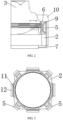
FIG. 1 is an exploded view of an electronic device according to this application; -
FIG. 2 is a half sectional view of a camera module; -
FIG. 3 is a top view of a movable support; -
FIG. 4 is a schematic diagram of an installation location of a microphone module of the electronic device; and -
FIG. 5 is a schematic diagram of an installation location of a microphone module in related technologies. - 1. Housing; 2. Movable support; 3. Lens; 4. Sound guide hole; 5. Microphone module; 6. Installation groove; 7. Flexible printed circuit board; 8. Camera support; 9. Shielding shell; 10. External housing; 11. Coil; 12. Magnet; 13. Spring plate.
- Embodiments of this application will be described in detail below. Examples of the embodiments are illustrated in the accompanying drawings, and same or similar reference numerals always indicate same or similar elements or elements having same or similar functions. The embodiments described below with reference to the accompanying drawings are examples, and are intended to only explain this application, but shall not be understood as a limitation on this application. Based on the embodiments of this application, all other embodiments obtained by a person of ordinary skill in the art without creative efforts fall within the protection scope of this application.
- Features of terms "first" and "second" in the specification and claims of this application may explicitly or implicitly include one or more of the features. In the descriptions of this application, unless otherwise stated, "a plurality of" means at least two. In addition, in the specification and the claims, "and/or" represents at least one of connected objects, and a character "/" generally represents an "or" relationship between associated objects.
- In the description of this application, it should be understood that an orientation or positional relationship indicated by the term "center", "longitudinal", "transverse", "length", "width", "thickness", "upper", "lower", "front", " back", "left", "right", "vertical", "horizontal", "top", "bottom", "internal", "external", "clockwise", "counterclockwise", "axial direction", "radial direction", "circumferential direction", or the like is based on an orientation or positional relationship shown in the accompanying drawings, and is merely for ease of describing this application and simplifying the description, but does not indicate or imply that an apparatus or an element referred to must have a specific orientation or be constructed and operated in a specific orientation, and therefore cannot be understood as a limitation on this application.
- In the description of this application, it should be noted that, unless expressly stipulated and defined otherwise, terms "install", " join", "connect", should be understood in a broad sense. For example, "connection" may be a fixed connection, a detachable connection, or an integral connection; may be a mechanical connection, or may be an electrical connection; or may be a direct connection, an indirect connection through an intermediate medium, or a connection between two elements. A person of ordinary skill in the art can understand specific meanings of these terms in this application based on specific situations.
- The following describes an electronic device according to embodiments of this application with reference to
FIG. 1 to FIG. 5 . - The electronic device according to some embodiments of this application includes a housing 1, a camera module, and a
microphone module 5. The housing 1 is anexternal housing 10 of the electronic device and protects electronic components inside the electronic device. For example, when the electronic device is a mobile phone, theexternal housing 10 is the housing 1 directly contacted by a user of the mobile phone. - The camera module is disposed in the housing 1, and is an anti-shake camera module. That is, a lens assembly of the camera module can make compensation with the shake of the electronic device held by an operator, so that the camera module can always shoot a clear photo or video. The camera module includes a
movable support 2. Themovable support 2 is a movable part in the anti-shake camera module. Movement of themovable support 2 is opposite to a shake direction. For example, if the shake direction is upward, themovable support 2 moves downward. The lens assembly is fixed on the movable support, so that the lens assembly can move along with themovable support 2. Themovable support 2 is movably disposed on the camera module, to achieve functions of anti-shake and focus adjustment for movement of themovable support 2, or achieve only a function of the anti-shake for the movement of themovable support 2 and focus adjustment for the lens assembly of the camera module. - The
microphone module 5 is disposed on themovable support 2, so that a microphone is close to the lens assembly and can move along with the moment of themovable support 2. The housing 1 is provided with a sound guide hole 4. A direction, facing the outside of the housing 1, of the sound guide hole 4 is the same as a shooting direction of the camera module, and the sound guide hole 4 is disposed opposite to themicrophone module 5. Themicrophone module 5 receives, through the sound guide hole 4, an audio signal from an object or a person photographed by the camera module. - For the electronic device according to embodiments of this application, the
microphone module 5 is disposed on themovable support 2 which drives alens 3 to move, so that the microphone is disposed close to thelens 3, and the microphone can move, when driven by themovable support 2, along with thelens 3. Further, a sound capturing direction of themicrophone module 5 is not changed due to shake. For example, before shake, a shooting direction of the lens assembly points to a shooting target, and the sound capturing direction of themicrophone module 5 also points to the shooting target. When or after the electronic device is shaking, the shooting direction of the lens assembly and the sound capturing direction of themicrophone module 5 still points to the shooting target as before shake. Therefore, an angle between a sound source and themicrophone module 5 is eliminated, making the sound source enter themicrophone module 5 at the same angle before and after shake of the electronic device, thereby improving a sound recording effect, and improving the sound recording effect more distinctly especially when shooting a distant view. - Further, the
microphone module 5 can be fastened to themovable support 2 by inlaying, adhering, welding, or the like, so that themicrophone module 5 can be reliably fastened to themovable support 2, ensuring that themicrophone module 5 can move along with themovable support 2 and improving the sound recording effect of themicrophone module 5. - Alternatively, a quantity of the
microphone modules 5 is at least three, and all themicrophone modules 5 are arranged on themovable support 2 at intervals. Eachmicrophone module 5 can receive an audio signal, and eachmicrophone module 5 is separated from each other by a distance, so that themicrophone modules 5 can record a shooting target in multiple directions, and the sound recording effect of themicrophone modules 5 can be improved. In addition, when there is a failure in one of themicrophone modules 5, remainingmicrophone modules 5 can be used for sound recording, preventing a risk that the electronic device cannot be used normally when only onemicrophone module 5 is disposed and damaged. - Alternatively, the
microphone modules 5 are disposed along a circumferential direction of a side wall of themovable support 2. Because a shooting direction of the lens assembly of the camera module of the electronic device is usually perpendicular to a plane in which the electronic device is located, that is, the camera module is disposed along a thickness direction of the electronic device, the camera module is successively provided with the lens assembly, themovable support 2, a base, and other components from outside to inside. Disposing themicrophone modules 5 on the side wall of themovable support 2 can reduce a size of the camera module occupied in the thickness direction of the electronic device as a whole and ensure the sound recording effect of themicrophone modules 5 on the premise of ensuring thinness of the electronic device. - Of course, the
microphone module 5 can also be disposed on an upper side of themovable support 2, to ensure the sound recording effect of themicrophone module 5 as well. Compared with that themicrophone module 5 is disposed on the side wall of themovable support 2, a thickness of the electronic device is increased, which cannot ensure a small thinness of the electronic device. - Further, all the
microphone modules 5 are uniformly disposed in the circumferential direction of the side wall of themovable support 2. Therefore, when the camera module drives themovable support 2 to move, it can be ensured that the center of gravity of themovable support 2 is stable, and it can be prevented that themovable support 2 is deflected and then stuck during movement, causing a failure in use of the anti-shake function. - Alternatively, an
installation groove 6 is disposed in themovable support 2, and themicrophone module 5 is disposed in theinstallation groove 6. Therefore, an overall volume of themovable support 2 provided with themicrophone module 5 can be reduced, saving internal space of the electronic device, increasing an integration level, and overall weight of themovable support 2 can be reduced, facilitating the camera module to drive themovable support 2 and reducing power consumption for driving themovable support 2. - Alternatively, the electronic device further includes a flexible printed
circuit board 7. Themicrophone modules 5 are electrically connected to the flexible printedcircuit board 7. The flexible printedcircuit board 7 is flexible and can bend and deform along with the movement of themicrophone module 5, ensuring power supply to themicrophone modules 5 and signal transmission of themicrophone modules 5. In addition, the flexible printedcircuit board 7 can be electrically connected to an image sensor and/or a motor of the camera module simultaneously, to supply power to achieve signal transmission of the image sensor and/or motor of the camera module. - Further, an inflexible circuit board is disposed under the camera module. The inflexible circuit board may be a motherboard or the like in electronic device. The flexible printed
circuit board 7 extending from the circuit board can ensure reliability of electrical connection and achieve power supply and signal transmission. - Alternatively, the housing 1 includes a camera support 8, and the sound guide hole 4 is disposed in the camera support 8. Because the camera module is disposed behind the camera support 8, the lens assembly of the camera module is disposed opposite to the camera support 8, and the lens assembly collects light through an opening on the camera support 8. The sound guide hole 4 is disposed in the camera support 8. Therefore, it can be ensured that the sound guide hole 4 is close to the lens assembly and adjacent to the
microphone module 5, and a better sound recording effect can be ensured. In addition, disposing the sound guide hole 4 is in the camera support 8 can simplify a processing technology, and the sound guide hole 4 can be simultaneously provided when the opening of the lens assembly is manufactured. - Alternatively, a shielding
shell 9 is installed outside themicrophone modules 5. The shieldingshell 9 can prevent a microphone magnetic field from interfering with a camera and an external magnetic field from interfering with a microphone. To concentrate a stray magnetic field on a body of the shieldingshell 9, the shieldingshell 9 should have magnetic permeability as high as possible. - Alternatively, the shielding
shell 9 is made of electromagnetic pure iron, permalloy, or ferritic stainless steel, all of which have relatively high magnetic permeability. Further, the shieldingshell 9 should be selected after comprehensive consideration of magnetic shield requirements, a price, strength, and processability of the housing 1. - Alternatively, the sound guide hole 4 is provided with a dust-proof element. The dust-proof element can prevent dust from entering the inside of the electronic device, and ensure that the inside of the electronic device is clean, to enable the electronic device to work normally.
- Alternatively, the camera module further includes the
external housing 10, acoil 11, and amagnet 12. Themagnet 12 is disposed on theexternal housing 10. Themagnet 12 and thecoil 11 are disposed opposite to each other on themovable support 2. After thecoil 11 is electrified, a magnetic field is generated. The magnetic field interacts with a magnetic field of a magnet to generate a driving force, to drive themovable support 2 to move. Further,spring plates 13 are installed at the top and bottom of themovable support 2 and can reset themovable support 2. - When the electronic device according to the embodiments of this application works, the camera module is driven to shoot a pictures of an object, a gyroscope senses shake of the electronic device, and the shake is converted to a driving current. The driving current acts on the
coil 11 to push themovable support 2 to move, and themovable support 2 drives thelens 3 and themicrophone module 5 to move, so that the sound recording direction of the microphone is the same as a direction of a shot object. - For example, the electronic device according to the embodiments of this application may be a mobile electronic device, including but not limited to a mobile phone, a tablet computer, a notebook computer, a palmtop computer, a vehicle-mounted electronic device, a wearable device, an ultra-mobile personal computer (ultra-mobile personal computer, UMPC), a netbook, a personal digital assistant (personal digital assistant, PDA), or the like.
- This application provides a sound recording method for an electronic device, applied to the foregoing electronic device. The electronic device includes a shake detection apparatus. The method includes the following steps.
- Obtain a shake parameter of the electronic device detected by the shake detection apparatus.
- The shake detection apparatus is disposed on the electronic device. When the electronic device shakes, the shake detection apparatus can detect the shake parameter of the electronic device. In this case, a processor can collect the shake parameter detected by the shake detection apparatus. For example, when the electronic device is a mobile phone, a camera module of the mobile phone is capturing an image in real time, and a hand of a user holding the mobile phone shakes, the shake detection apparatus can monitor shake and collect a shake parameter in real time. The shake parameter can be obtained by the processor. The shake parameter can also be obtained by the electronic device, or the like.
- Drive, based on the shake parameter, the
movable support 2 to deflect, so that themicrophone module 5 moves along with themovable support 2. - Driving the
movable support 2 based on the shake parameter may be that the processor converts the shake parameter to a driving current. As the shake parameter is different, a parameter such as a value of the driving current by conversion is different. The driving current drives a motor to drive themovable support 2 to move, and themovable support 2 drives a lens assembly, to enable a shooting direction of the lens assembly to face a shooting target. Themicrophone module 5 is disposed on themovable support 2, so that themicrophone module 5 and the lens assembly can move synchronously. Therefore, it can be prevented that the lens assembly moves but themicrophone module 5 does not move. Further, a sound capturing direction of themicrophone module 5 is not changed due to shake. For example, before shake, a shooting direction of the lens assembly points to a shooting target, and the sound capturing direction of themicrophone module 5 also points to the shooting target. When or after the electronic device is shaking, the shooting direction of the lens assembly and the sound capturing direction of themicrophone module 5 still points to the shooting target as before shake. Therefore, an angle between a sound source and themicrophone module 5 is eliminated, making the sound source enter themicrophone module 5 at the same angle before and after shake of the electronic device, thereby improving a sound recording effect. The shooting target is an object or image selected by a user and to be shot by the electronic device. - Alternatively, the shake parameter includes a shake direction and a shake angle of the electronic device, and driving the
movable support 2 based on the shake parameter includes driving themovable support 2 to deflect at the shake angle along a compensation direction. The compensation direction is opposite to the shake direction. For example, if the shake parameter of the electronic device is 3 degrees to the left, themovable support 2 is 3 degrees to the right. The shake direction and the shake angle can be obtained indirectly. For example, the shake detection apparatus can directly output acceleration values of different coordinates, and correspond to the shake direction and the shake angle based on the positive and negative and a value of the acceleration. In addition, the shake parameter may further include a deflection angular velocity and the like. - Alternatively, the shake detection apparatus includes a gyroscope. The gyroscope works stably and can reliably ensure a relative position relationship between the
microphone module 5 and a sound source and ensure sound recording quality. - In the description of this specification, descriptions with reference to the term such as "an embodiment", "some embodiments", "exemplary embodiment", "example", "specific example", or "some examples" mean that a specific feature, structure, materia, or characteristic described with reference to the embodiment or example are included in at least one embodiment or example of this application. In this specification, illustrative expressions of these terms do not necessarily refer to the same embodiment or example. Moreover, the specific feature, structure, material, or characteristic described may be combined in any suitable manner in any one or more embodiments or examples.
- Although the embodiments of this application have been shown and described, those skilled in the art can understand that a plurality of changes, modifications, substitutions, and variations can be made to these embodiments without departing from the principle and purpose of this application, and the scope of this application is defined by the claims and their equivalents.
Claims (10)
- An electronic device, comprising:a housing, wherein the housing is provided with a sound guide hole;a camera module, wherein the camera module is disposed in the housing and comprises a movable support, a lens assembly is fixed on the movable support, and the movable support is movably disposed on the camera module; anda microphone module disposed on the movable support,wherein a direction, facing the outside of the housing, of the sound guide hole is same as a shooting direction of the camera module, and the sound guide hole is disposed opposite to the microphone module.
- The electronic device according to claim 1, wherein a quantity of the microphone modules is at least three, and all the microphone modules are arranged on the movable support at intervals.
- The electronic device according to claim 1 or 2, wherein the microphone modules are disposed along a circumferential direction of a side wall of the movable support.
- The electronic device according to any one of claims 1 to 3, wherein an installation groove is disposed in the movable support, and the microphone module is disposed in the installation groove.
- The electronic device according to any one of claims 1 to 4, wherein the electronic device further comprises a flexible printed circuit board, and the microphone module is electrically connected to the flexible printed circuit board.
- The electronic device according to any one of claims 1 to 5, wherein the housing comprises a camera support, and the sound guide hole is disposed in the camera support.
- The electronic device according to any one of claims 1 to 6, wherein a shielding shell is installed outside the microphone module, and the shielding shell is made of at least one of electromagnetic pure iron, permalloy, or ferritic stainless steel.
- A sound recording method for an electronic device, applied to the electronic device according to any one of claims 1 to 7, wherein the electronic device comprises a shake detection apparatus and the method comprises:obtaining a shake parameter of the electronic device detected by the shake detection apparatus; anddriving, based on the shake parameter, the movable support to deflect, so that the microphone module moves along with the movable support.
- The sound recording method for an electronic device according to claim 8, wherein the shake parameter comprises a shake direction and a shake angle of the electronic device, and the driving, based on the shake parameter, the movable support comprises driving the movable support to deflect at the shake angle along a compensation direction, wherein the compensation direction is a direction opposite to the shake direction.
- The sound recording method for an electronic device according to claim 8 or 9, wherein the shake detection apparatus comprises a gyroscope.
Applications Claiming Priority (2)
| Application Number | Priority Date | Filing Date | Title |
|---|---|---|---|
| CN202011514026.XA CN112492430B (en) | 2020-12-17 | 2020-12-17 | Electronic devices and recording methods for electronic devices |
| PCT/CN2021/137166 WO2022127710A1 (en) | 2020-12-17 | 2021-12-10 | Electronic device, and sound recording method for electronic device |
Publications (2)
| Publication Number | Publication Date |
|---|---|
| EP4266697A1 true EP4266697A1 (en) | 2023-10-25 |
| EP4266697A4 EP4266697A4 (en) | 2024-08-14 |
Family
ID=74915129
Family Applications (1)
| Application Number | Title | Priority Date | Filing Date |
|---|---|---|---|
| EP21905639.7A Pending EP4266697A4 (en) | 2020-12-17 | 2021-12-10 | ELECTRONIC DEVICE, AND SOUND RECORDING METHOD FOR ELECTRONIC DEVICE |
Country Status (4)
| Country | Link |
|---|---|
| US (1) | US20240040024A1 (en) |
| EP (1) | EP4266697A4 (en) |
| CN (1) | CN112492430B (en) |
| WO (1) | WO2022127710A1 (en) |
Families Citing this family (2)
| Publication number | Priority date | Publication date | Assignee | Title |
|---|---|---|---|---|
| CN112492430B (en) * | 2020-12-17 | 2023-12-15 | 维沃移动通信有限公司 | Electronic devices and recording methods for electronic devices |
| WO2025080275A1 (en) | 2023-10-13 | 2025-04-17 | Google Llc | Magnetically self-shielded speaker box for a mobile device |
Family Cites Families (22)
| Publication number | Priority date | Publication date | Assignee | Title |
|---|---|---|---|---|
| JPH11341592A (en) * | 1998-05-28 | 1999-12-10 | Mitsubishi Electric Corp | A recording device that tunes to the imaging device |
| JP2003259180A (en) * | 2002-03-06 | 2003-09-12 | Kosuke Ose | Support frame with camera-shake preventing and remote control function for handy video camera and stereo sound-recording function |
| JP5391008B2 (en) * | 2009-09-16 | 2014-01-15 | キヤノン株式会社 | Imaging apparatus and control method thereof |
| US10477742B2 (en) * | 2014-09-08 | 2019-11-12 | Apple Inc. | Shield for acoustic device |
| CN206541375U (en) * | 2017-01-13 | 2017-10-03 | 深圳优派汉王触控科技有限公司 | Password input terminal |
| US10101777B1 (en) * | 2017-04-08 | 2018-10-16 | Lenovo (Singapore) Pte. Ltd. | Retractable camera |
| CN207503048U (en) * | 2017-12-01 | 2018-06-15 | 深圳市悠响声学科技有限公司 | A kind of audio source tracking circuit of robot |
| CN107948524A (en) * | 2017-12-21 | 2018-04-20 | 重庆金鑫科技产业发展有限公司 | A kind of camera |
| CN108307004A (en) * | 2017-12-26 | 2018-07-20 | 姜洪明 | Full-screen mobile phone and its recognition of face verification method |
| CN108957392A (en) * | 2018-04-16 | 2018-12-07 | 深圳市沃特沃德股份有限公司 | Sounnd source direction estimation method and device |
| CN208434079U (en) * | 2018-07-27 | 2019-01-25 | 深圳市大疆创新科技有限公司 | Microphone Mounting Brackets, Microphone Assemblies, and Electronics |
| CN110958512B (en) * | 2018-09-27 | 2025-07-25 | 北京小米移动软件有限公司 | Microphone module and terminal equipment |
| CN112055102B (en) * | 2019-06-06 | 2021-10-15 | 华为技术有限公司 | A camera module, video camera and mobile terminal |
| CN110351465A (en) * | 2019-07-18 | 2019-10-18 | 珠海格力电器股份有限公司 | Anti-shake camera module and anti-shake method thereof |
| CN210670256U (en) * | 2019-10-10 | 2020-06-02 | 北京小米移动软件有限公司 | Camera module and electronic equipment |
| CN210807424U (en) * | 2019-11-26 | 2020-06-19 | 维沃移动通信有限公司 | Microphone module, camera module and electronic equipment |
| CN210958487U (en) * | 2019-12-24 | 2020-07-07 | 山东信通电子股份有限公司 | Shooting equipment |
| CN111212209B (en) * | 2020-02-28 | 2021-11-16 | 维沃移动通信有限公司 | Camera module and electronic equipment |
| CN211830943U (en) * | 2020-05-28 | 2020-10-30 | 维沃移动通信有限公司 | Camera module and electronic equipment |
| CN111901524B (en) * | 2020-07-22 | 2022-04-26 | 维沃移动通信有限公司 | Focusing method and device and electronic equipment |
| CN111916102B (en) * | 2020-07-31 | 2024-05-28 | 维沃移动通信有限公司 | Recording method and recording device of electronic equipment |
| CN112492430B (en) * | 2020-12-17 | 2023-12-15 | 维沃移动通信有限公司 | Electronic devices and recording methods for electronic devices |
-
2020
- 2020-12-17 CN CN202011514026.XA patent/CN112492430B/en active Active
-
2021
- 2021-12-10 WO PCT/CN2021/137166 patent/WO2022127710A1/en not_active Ceased
- 2021-12-10 EP EP21905639.7A patent/EP4266697A4/en active Pending
-
2023
- 2023-06-15 US US18/210,647 patent/US20240040024A1/en active Pending
Also Published As
| Publication number | Publication date |
|---|---|
| CN112492430B (en) | 2023-12-15 |
| US20240040024A1 (en) | 2024-02-01 |
| EP4266697A4 (en) | 2024-08-14 |
| WO2022127710A1 (en) | 2022-06-23 |
| CN112492430A (en) | 2021-03-12 |
Similar Documents
| Publication | Publication Date | Title |
|---|---|---|
| EP4266672A1 (en) | Driving device and electronic apparatus | |
| EP3373562B1 (en) | Terminal having camera module | |
| US20240040024A1 (en) | Electronic device and sound recording method for electronic device | |
| KR102709039B1 (en) | Electronic device including microphone | |
| US20210021744A1 (en) | Camera module and optical device comprising same | |
| EP4171007B1 (en) | CAMERA MODULE AND ELECTRONIC DEVICE | |
| TWI663462B (en) | Lens driving apparatus, photographing module and electronic device | |
| WO2022100580A1 (en) | Voice coil motor, camera module, and electronic device | |
| CN101877731B (en) | Camera device and portable electronic device with same | |
| US12477225B2 (en) | Camera structure and electronic device with anti-shake function | |
| CN113489887B (en) | Anti-shake mechanism, imaging device, and electronic apparatus | |
| CN210016389U (en) | Triaxial anti-shake periscope motor | |
| US20250374418A1 (en) | Camera module | |
| CN112540444B (en) | Lens module and electronics | |
| CN119697305A (en) | Electronic device including camera module | |
| US12563297B2 (en) | Motor, camera module, and electronic device | |
| EP4686055A1 (en) | Motor, camera module and electronic device | |
| CN216253000U (en) | Camera module and electronic equipment | |
| TW202208913A (en) | Imaging lens assembly module, imaging lens assembly driving module and electronic device | |
| CN219938132U (en) | Camera motor, camera module and electronic equipment | |
| CN219659807U (en) | Motor assembly, camera module and electronic equipment | |
| CN113114873A (en) | Camera module and electronic equipment | |
| EP4648431A1 (en) | Camera assembly and electronic device | |
| CN116668826B (en) | Drive unit, camera module and electronic equipment | |
| CN120835194A (en) | Motors, camera modules and electronic equipment |
Legal Events
| Date | Code | Title | Description |
|---|---|---|---|
| STAA | Information on the status of an ep patent application or granted ep patent |
Free format text: STATUS: THE INTERNATIONAL PUBLICATION HAS BEEN MADE |
|
| PUAI | Public reference made under article 153(3) epc to a published international application that has entered the european phase |
Free format text: ORIGINAL CODE: 0009012 |
|
| STAA | Information on the status of an ep patent application or granted ep patent |
Free format text: STATUS: REQUEST FOR EXAMINATION WAS MADE |
|
| 17P | Request for examination filed |
Effective date: 20230710 |
|
| AK | Designated contracting states |
Kind code of ref document: A1 Designated state(s): AL AT BE BG CH CY CZ DE DK EE ES FI FR GB GR HR HU IE IS IT LI LT LU LV MC MK MT NL NO PL PT RO RS SE SI SK SM TR |
|
| DAV | Request for validation of the european patent (deleted) | ||
| DAX | Request for extension of the european patent (deleted) | ||
| RIC1 | Information provided on ipc code assigned before grant |
Ipc: H04R 1/40 20060101ALN20240419BHEP Ipc: H04M 1/02 20060101ALN20240419BHEP Ipc: H04N 23/57 20230101ALI20240419BHEP Ipc: H04N 23/52 20230101ALI20240419BHEP Ipc: H04N 23/51 20230101ALI20240419BHEP Ipc: H04M 1/03 20060101ALI20240419BHEP Ipc: H04R 1/08 20060101AFI20240419BHEP |
|
| A4 | Supplementary search report drawn up and despatched |
Effective date: 20240716 |
|
| RIC1 | Information provided on ipc code assigned before grant |
Ipc: H04R 1/40 20060101ALN20240710BHEP Ipc: H04M 1/02 20060101ALN20240710BHEP Ipc: H04N 23/57 20230101ALI20240710BHEP Ipc: H04N 23/52 20230101ALI20240710BHEP Ipc: H04N 23/51 20230101ALI20240710BHEP Ipc: H04M 1/03 20060101ALI20240710BHEP Ipc: H04R 1/08 20060101AFI20240710BHEP |
|
| STAA | Information on the status of an ep patent application or granted ep patent |
Free format text: STATUS: EXAMINATION IS IN PROGRESS |
|
| 17Q | First examination report despatched |
Effective date: 20260209 |