EP4266648A1 - Apparatus for setting communication id of energy storage system - Google Patents
Apparatus for setting communication id of energy storage system Download PDFInfo
- Publication number
- EP4266648A1 EP4266648A1 EP21906892.1A EP21906892A EP4266648A1 EP 4266648 A1 EP4266648 A1 EP 4266648A1 EP 21906892 A EP21906892 A EP 21906892A EP 4266648 A1 EP4266648 A1 EP 4266648A1
- Authority
- EP
- European Patent Office
- Prior art keywords
- power
- battery
- communication
- setting
- supplied
- Prior art date
- Legal status (The legal status is an assumption and is not a legal conclusion. Google has not performed a legal analysis and makes no representation as to the accuracy of the status listed.)
- Pending
Links
Images

Classifications
-
- H—ELECTRICITY
- H01—ELECTRIC ELEMENTS
- H01M—PROCESSES OR MEANS, e.g. BATTERIES, FOR THE DIRECT CONVERSION OF CHEMICAL ENERGY INTO ELECTRICAL ENERGY
- H01M10/00—Secondary cells; Manufacture thereof
- H01M10/42—Methods or arrangements for servicing or maintenance of secondary cells or secondary half-cells
- H01M10/425—Structural combination with electronic components, e.g. electronic circuits integrated to the outside of the casing
-
- H—ELECTRICITY
- H04—ELECTRIC COMMUNICATION TECHNIQUE
- H04L—TRANSMISSION OF DIGITAL INFORMATION, e.g. TELEGRAPHIC COMMUNICATION
- H04L61/00—Network arrangements, protocols or services for addressing or naming
- H04L61/50—Address allocation
- H04L61/5038—Address allocation for local use, e.g. in LAN or USB networks, or in a controller area network [CAN]
-
- H—ELECTRICITY
- H04—ELECTRIC COMMUNICATION TECHNIQUE
- H04L—TRANSMISSION OF DIGITAL INFORMATION, e.g. TELEGRAPHIC COMMUNICATION
- H04L61/00—Network arrangements, protocols or services for addressing or naming
- H04L61/30—Managing network names, e.g. use of aliases or nicknames
- H04L61/3015—Name registration, generation or assignment
- H04L61/302—Administrative registration, e.g. for domain names at internet corporation for assigned names and numbers [ICANN]
-
- H—ELECTRICITY
- H02—GENERATION; CONVERSION OR DISTRIBUTION OF ELECTRIC POWER
- H02J—ELECTRIC POWER NETWORKS; CIRCUIT ARRANGEMENTS OR SYSTEMS FOR SUPPLYING OR DISTRIBUTING ELECTRIC POWER; SYSTEMS FOR STORING ELECTRIC ENERGY
- H02J7/00—Circuit arrangements for charging or discharging batteries or for supplying loads from batteries
- H02J7/40—Circuit arrangements for charging or discharging batteries or for supplying loads from batteries characterised by the exchange of charge or discharge related data
- H02J7/44—Circuit arrangements for charging or discharging batteries or for supplying loads from batteries characterised by the exchange of charge or discharge related data between battery management systems and power sources
-
- H—ELECTRICITY
- H02—GENERATION; CONVERSION OR DISTRIBUTION OF ELECTRIC POWER
- H02J—ELECTRIC POWER NETWORKS; CIRCUIT ARRANGEMENTS OR SYSTEMS FOR SUPPLYING OR DISTRIBUTING ELECTRIC POWER; SYSTEMS FOR STORING ELECTRIC ENERGY
- H02J7/00—Circuit arrangements for charging or discharging batteries or for supplying loads from batteries
- H02J7/50—Circuit arrangements for charging or discharging batteries or for supplying loads from batteries acting upon multiple batteries simultaneously or sequentially
- H02J7/52—Circuit arrangements for charging or discharging batteries or for supplying loads from batteries acting upon multiple batteries simultaneously or sequentially for charge balancing, e.g. equalisation of charge between batteries
- H02J7/56—Active balancing, e.g. using capacitor-based, inductor-based or DC-DC converters
-
- H—ELECTRICITY
- H02—GENERATION; CONVERSION OR DISTRIBUTION OF ELECTRIC POWER
- H02J—ELECTRIC POWER NETWORKS; CIRCUIT ARRANGEMENTS OR SYSTEMS FOR SUPPLYING OR DISTRIBUTING ELECTRIC POWER; SYSTEMS FOR STORING ELECTRIC ENERGY
- H02J7/00—Circuit arrangements for charging or discharging batteries or for supplying loads from batteries
- H02J7/865—Battery or charger load switching, e.g. concurrent charging and load supply
-
- H—ELECTRICITY
- H04—ELECTRIC COMMUNICATION TECHNIQUE
- H04B—TRANSMISSION
- H04B3/00—Line transmission systems
- H04B3/54—Systems for transmission via power distribution lines
- H04B3/544—Setting up communications; Call and signalling arrangements
-
- H—ELECTRICITY
- H04—ELECTRIC COMMUNICATION TECHNIQUE
- H04B—TRANSMISSION
- H04B3/00—Line transmission systems
- H04B3/54—Systems for transmission via power distribution lines
- H04B3/548—Systems for transmission via power distribution lines the power on the line being DC
-
- H—ELECTRICITY
- H01—ELECTRIC ELEMENTS
- H01M—PROCESSES OR MEANS, e.g. BATTERIES, FOR THE DIRECT CONVERSION OF CHEMICAL ENERGY INTO ELECTRICAL ENERGY
- H01M10/00—Secondary cells; Manufacture thereof
- H01M10/42—Methods or arrangements for servicing or maintenance of secondary cells or secondary half-cells
- H01M10/425—Structural combination with electronic components, e.g. electronic circuits integrated to the outside of the casing
- H01M2010/4271—Battery management systems including electronic circuits, e.g. control of current or voltage to keep battery in healthy state, cell balancing
-
- H—ELECTRICITY
- H01—ELECTRIC ELEMENTS
- H01M—PROCESSES OR MEANS, e.g. BATTERIES, FOR THE DIRECT CONVERSION OF CHEMICAL ENERGY INTO ELECTRICAL ENERGY
- H01M10/00—Secondary cells; Manufacture thereof
- H01M10/42—Methods or arrangements for servicing or maintenance of secondary cells or secondary half-cells
- H01M10/425—Structural combination with electronic components, e.g. electronic circuits integrated to the outside of the casing
- H01M2010/4278—Systems for data transfer from batteries, e.g. transfer of battery parameters to a controller, data transferred between battery controller and main controller
Definitions
- the present invention relates to an apparatus for setting a communication ID of an energy storage system, and more particularly, to an apparatus capable of automatically setting a communication ID for each battery.
- An energy storage system is applied to new and renewable energy generation where the amount of charge is not constant, and plays a role to store generated surplus power and to supplement when the amount of power generation is insufficient compared to the amount of power at the load end.
- An ESS usually uses lithium-ion batteries connected in parallel, and a battery management system is applied to each battery to detect the state of the battery and communicate with a higher level power conditioning system.
- a battery management system receives power from a power conditioning system and operates and is connected to a power line receiving the power and a communication line for communication.
- each of the plurality of batteries needs to be wired into the power conditioning system and a communication line and a power line, and when the ESS is installed, a worker needs to connect each of the wires.
- the communication ID needs to be manually set using a communication ID setting switch provided in each of the battery management systems.
- FIG. 1 illustrates a structure of wiring and communication ID setting of a conventional ESS.
- a battery parallel wired structure of a conventional ESS represents a connection structure between a power conditioning system 100 and power lines and communication lines of a plurality of battery management systems 200.
- the power conditioning system 100 includes a power supply 110 for supplying power of a PV or a power grid to the plurality of battery management systems 200, and a master communicator 120 for communication with each battery management system 200.
- each of the plurality of battery management systems 200 includes a power 210 receiving power from the power supply 110 through a parallel power line 300, a slave communicator 220 connected to the master communicator 120 through a parallel communication line 400 and providing information such as a state of a battery, and a switch 230 for setting an ID of the slave communicator 220.
- the power conditioning system 100 is a system for converting DC/DC between the PV and a battery 500 or AC/DC power between the power grid and the battery 500, and includes a power supply 110 for supplying power to each battery management system 200 as described above.
- the power of the power supply 110 is supplied to the power 210 of the battery management system 200, which manages the battery 500 of each storage device through the parallel power line 300.
- the power conditioning system 100 may perform wired communication with the slave communicators 220 of the battery management system 200 through the master communicator 120 to identify state information of the battery 500, and for this, the parallel communication line 400 is wired between the master communicator 120 and the slave communicator 220.
- a worker operates the switch 230 to set an ID of each slave communicator 220.
- the present invention is directed to providing an apparatus for setting a communication ID for an energy storage system that can automatically set an ID without using a switch.
- the apparatus for setting a communication ID of an energy storage system of the present invention for solving the above problem includes a power converter for selecting one power line from among a plurality of power lines to supply power through the selected power line; and battery managers which are sequentially connected to the power converter and are operated by the power selectively supplied through the one power line selected from among the plurality of power lines, wherein the power converter may communicate with one battery manager which is operated by the supplied power from among the battery managers.
- the power converter may include a power supply for supplying power; a selector for selecting one of the plurality of power lines connected to a power output port of the power converter and output the power of the power supply; and a master communicator for communicating with a battery manager selected by the selector and supplied with power.
- the power converter may control switching of a plurality of switches constituting the selector and process data received through the master communicator by matching it with the battery manager that is supplied with power and operated.
- the selector may include the plurality of switches having one end connected to one of a first power line and a second power line from which power is output from the power supply, and sub power lines connecting the other end of each of the plurality of switches and the battery manager.
- the present invention provides a power conditioning system to selectively supply power to battery management systems and communicate with the battery management system to which power is supplied, thereby enabling communication without setting a separate communication ID, thereby preventing communication errors caused by an ID setting error.
- a communication ID is set by using a selective power supply and a setting of an ID according to the selective power supply without manually setting a communication ID by a worker, a configuration of a switch that needs to be installed for each battery management system can be omitted, and thus a hardware configuration can be simplified, a size of an apparatus can be reduced, and a cost can be reduced, and a system installation operation can be simplified, and thus time and cost can be reduced.
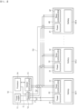
- FIG. 2 is a block diagram of an apparatus for setting a communication ID of an energy storage system according to a preferred embodiment of the present invention.
- the apparatus for setting a communication ID of an energy storage system selectively supplies power to each of the battery managers 20, 30, 40 by using power lines P, G1 to Gn as many as the number of battery managers 20, 30, 40, which are slave devices, from the power converter 10 which is the master device.
- the number of battery managers 20, 30, 40 is arbitrarily determined according to the size of the energy storage system, and three battery managers 20, 30, 40 are shown and described in the present invention for convenience of description.
- the battery manager 20 may be described as a first battery manager 20, the battery manager 30 may be described as a second battery manager 30, and the battery manager 40 may be described as a last battery manager 40.
- the configurations of the battery managers 20, 30, 40 are the same, and each include a power 21, 31, and 41, and each include a slave communicator 22, 32, and 42 for communication with the power converter 10.
- Each of the slave communicators 22, 32, and 42 of the battery managers 20, 30, and 40 transmits state information of the assigned batteries 50-1 to 50-n.
- the power converter 10 includes a power supply 11 for supplying power to each of the battery managers 20, 30, and 40, and a master communicator 13 for communication with the battery managers 20, 30, and 40.
- the power supply 11 may supply DC power through a positive electrode line P and a negative electrode line G.
- the positive electrode line P of the power supply 11 is connected in parallel to the powers 21, 31, and 41 of all the battery managers 20, 30, and 40, and the negative electrode line G is divided into a plurality of negative electrode lines G1 to Gn through the selector 12, respectively, and is connected in series to the power supplies 21, 31, and 41.
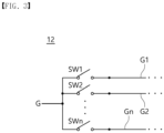
- FIG. 3 is a configuration diagram of the selector 12.
- the selector 12 includes a plurality of switches SW1 to SWn having one end connected to the negative electrode line G of the power supply 11.
- n is a positive integer.
- the other ends of the switches SW1 to SWn may be connected to one end of sub negative electrode lines G1 to Gn, respectively, and power may be supplied to the powers 21, 31, and 41 of the battery managers 20, 30, and 40 through the sub negative electrode lines G1 to Gn selected according to the states of the switches SW1 to SWn.
- the switching of the switches SW1 to SWn is performed by the control of a processor 14.
- the switches SW1 to SWn may be transistors.
- the processor 14 of the power converter 10 controls the selector 12 to close the switch SW1 and keep the remaining switches SW2 to SWn open during an initial operation in a state in which installation such as wiring is completed.
- the processor 14 may specify the battery manager 20 to which the power of the power supply 11 is supplied as the switch SW1 is closed.
- the battery manager 20 may operate according to the supply of power and detect the state of the battery 50-1.
- the battery manger 20 may check the state of the battery 50-1 by using information obtained from the sensors, including various sensors and processors.
- the processor 14 of the power converter 10 may transmit a request for checking the state of the battery by using the master communicator 13.
- the request is not specific to the battery manager 20, 30, or 40, which is the receiving side.
- the slave communicator 22 of the battery manager 20 may receive a request from the master communicator 13.
- the battery manager 20 that has received the request of the master communicator 13 transmits information such as the state of the battery 50-1.
- the slave communicator 22 of the battery manager 20 transmits data representing the battery state in a state in which its own ID is not set and the ID of the master communicator 13, which is the receiving side, is not set either.
- This data is received by the master communicator 13, and in this case, the processor 14 may match the received battery information with the battery manager 20 that is currently supplied with power and operates.
- the matched information may be stored in an internal or external memory of the processor.
- the processor 14 of the power converter 10 opens the switch SW1 of the selector 12 and closes the second switch SW2 to allow power from the power supply 11 to be supplied to the second battery manager 30.
- the processor 14 transmits a signal for requesting transmission of the state information through the master communicator 13, which is received by the slave communicator 32 of the second battery manager 30, which is currently supplied with power and operates.
- the slave communicator 32 that received the request for transmission transmits the state information of the battery 50-2, which may be received by the master communicator 13 and matched with the battery manager 30, which is currently supplied with power, and stored.
- This stored information can be used for balancing control that equalizes the state of charge of each battery.
- the processor 14 selectively sequentially controls the switches of the selector 12 to allow power to be supplied to only one battery manager and communicates with the powered battery manager, so that a separate ID setting is not required.
- the control of the selector 12 of the processor 14 is sequentially repeated to close the last switch SWn and open all other switches SW1 to SWn-1 so that power is supplied to the last battery manager 40.
- the request is received by the slave communicator 42 of the battery manager 40, which operates according to the supply of power, and the slave communicator 42 transmits information confirming the state of the battery 50-n.
- the data transmitted by the slave communicator 42 is received by the master communicator 13 and matched with the battery manager 40 and stored.
- the present invention can perform individual communication without setting the IDs of all the battery managers 20, 30 and 40.
- the present invention proposes an apparatus capable of individual communication without using an ID of a battery manager of an energy storage system using natural laws, and has industrial applicability.
Landscapes
- Engineering & Computer Science (AREA)
- Power Engineering (AREA)
- Computer Networks & Wireless Communication (AREA)
- Signal Processing (AREA)
- Manufacturing & Machinery (AREA)
- Chemical Kinetics & Catalysis (AREA)
- Electrochemistry (AREA)
- General Chemical & Material Sciences (AREA)
- Chemical & Material Sciences (AREA)
- Microelectronics & Electronic Packaging (AREA)
- Charge And Discharge Circuits For Batteries Or The Like (AREA)
- Mobile Radio Communication Systems (AREA)
- Cash Registers Or Receiving Machines (AREA)
Abstract
Description
- The present invention relates to an apparatus for setting a communication ID of an energy storage system, and more particularly, to an apparatus capable of automatically setting a communication ID for each battery.
- An energy storage system (ESS) is applied to new and renewable energy generation where the amount of charge is not constant, and plays a role to store generated surplus power and to supplement when the amount of power generation is insufficient compared to the amount of power at the load end.
- An ESS usually uses lithium-ion batteries connected in parallel, and a battery management system is applied to each battery to detect the state of the battery and communicate with a higher level power conditioning system.
- In general, a battery management system (BMS) receives power from a power conditioning system and operates and is connected to a power line receiving the power and a communication line for communication.
- That is, each of the plurality of batteries needs to be wired into the power conditioning system and a communication line and a power line, and when the ESS is installed, a worker needs to connect each of the wires.
- In addition, the communication ID needs to be manually set using a communication ID setting switch provided in each of the battery management systems.
- If a worker accidentally mis-set the communication ID during the process of setting the communication ID, a communication error may occur, and in order to solve the error, each battery management system needs to be checked again, and thus, there was a problem in that time and cost may be lost.
-
FIG. 1 illustrates a structure of wiring and communication ID setting of a conventional ESS. - Referring to
FIG. 1 , a battery parallel wired structure of a conventional ESS represents a connection structure between apower conditioning system 100 and power lines and communication lines of a plurality ofbattery management systems 200. - The
power conditioning system 100 includes apower supply 110 for supplying power of a PV or a power grid to the plurality ofbattery management systems 200, and amaster communicator 120 for communication with eachbattery management system 200. - In addition, each of the plurality of
battery management systems 200 includes apower 210 receiving power from thepower supply 110 through aparallel power line 300, aslave communicator 220 connected to themaster communicator 120 through a parallel communication line 400 and providing information such as a state of a battery, and aswitch 230 for setting an ID of theslave communicator 220. - A conventional wiring method of such a structure will be described in more detail.
- The
power conditioning system 100 is a system for converting DC/DC between the PV and abattery 500 or AC/DC power between the power grid and thebattery 500, and includes apower supply 110 for supplying power to eachbattery management system 200 as described above. - The power of the
power supply 110 is supplied to thepower 210 of thebattery management system 200, which manages thebattery 500 of each storage device through theparallel power line 300. - In addition, the
power conditioning system 100 may perform wired communication with theslave communicators 220 of thebattery management system 200 through themaster communicator 120 to identify state information of thebattery 500, and for this, the parallel communication line 400 is wired between themaster communicator 120 and theslave communicator 220. - In this case, a worker operates the
switch 230 to set an ID of eachslave communicator 220. - As many parallel communication lines 400 as the number of
battery management systems 200 are required between thepower conditioning system 100 and thebattery management system 200, and a worker needs to wire each parallel communication line 400. - That is, a lot of work time is required, and the complexity of the work further increases when the distance between the
power conditioning system 100 and thebattery management system 200 is long or the number ofbattery management systems 200 is large. - Therefore, erroneous wiring frequently occurs by workers, and products may be damaged or errors may occur due to erroneous wiring.
- In addition, when a communication error occurs after work, a task for finding the cause and solving the error becomes a very difficult and complicated task.
- In particular, if a worker sets IDs of two or more
battery management systems 200 identically, normal operation cannot be performed, and there was a problem in that switch states of a plurality ofbattery management systems 200 need to be checked again to find the cause. - In addition, there is a problem in that the relative size of the product increases due to the addition of the switch, or difficulties may occur in attaching and operating the switch due to a narrow space.
- In order to solve the above problems, the present invention is directed to providing an apparatus for setting a communication ID for an energy storage system that can automatically set an ID without using a switch.
- The apparatus for setting a communication ID of an energy storage system of the present invention for solving the above problem includes a power converter for selecting one power line from among a plurality of power lines to supply power through the selected power line; and battery managers which are sequentially connected to the power converter and are operated by the power selectively supplied through the one power line selected from among the plurality of power lines, wherein the power converter may communicate with one battery manager which is operated by the supplied power from among the battery managers.
- In an embodiment of the present invention, the power converter may include a power supply for supplying power; a selector for selecting one of the plurality of power lines connected to a power output port of the power converter and output the power of the power supply; and a master communicator for communicating with a battery manager selected by the selector and supplied with power.
- In an embodiment of the present invention, the power converter may control switching of a plurality of switches constituting the selector and process data received through the master communicator by matching it with the battery manager that is supplied with power and operated.
- In an embodiment of the present invention, the selector may include the plurality of switches having one end connected to one of a first power line and a second power line from which power is output from the power supply, and sub power lines connecting the other end of each of the plurality of switches and the battery manager.
- The present invention provides a power conditioning system to selectively supply power to battery management systems and communicate with the battery management system to which power is supplied, thereby enabling communication without setting a separate communication ID, thereby preventing communication errors caused by an ID setting error.
- According to the present invention, since a communication ID is set by using a selective power supply and a setting of an ID according to the selective power supply without manually setting a communication ID by a worker, a configuration of a switch that needs to be installed for each battery management system can be omitted, and thus a hardware configuration can be simplified, a size of an apparatus can be reduced, and a cost can be reduced, and a system installation operation can be simplified, and thus time and cost can be reduced.
-
-
FIG. 1 is a structure diagram of wiring and communication ID setting of a conventional energy storage system. -
FIG. 2 is a block diagram of an apparatus for setting a communication ID of an energy storage system according to a preferred embodiment of the present invention. -
FIG. 3 is a configuration diagram of one implementation of a selector. - Hereinafter, in order to fully understand the configuration and effects of the present invention, preferred embodiments of the present invention will be described with reference to the accompanying drawings. However, the present invention is not limited to the embodiments disclosed below, and may be embodied in various forms and various modifications may be made. Rather, the description of the present invention is provided so that the present disclosure will be thorough and complete and will fully convey the scope of the invention to those of ordinary skill in the art. In the accompanying drawings, the size of the elements is enlarged compared to actual ones for the convenience of description, and the ratio of each element may be exaggerated or reduced.
- Terms such as 'first' and 'second' may be used to describe various elements, but, the above elements should not be limited by the terms above. The above terms may be used only for the purpose of distinguishing one element from another. For example, without departing from the scope of the present invention, a 'first element' may be named a 'second element' and similarly, a 'second element' may also be named a 'first element.' In addition, expressions in the singular include plural expressions unless explicitly expressed otherwise in the context. Unless otherwise defined, terms used in the embodiments of the present invention may be interpreted as meanings commonly known to those of ordinary skill in the art.
-
FIG. 2 is a block diagram of an apparatus for setting a communication ID of an energy storage system according to a preferred embodiment of the present invention. - Referring to
FIG. 2 , the apparatus for setting a communication ID of an energy storage system according to a preferred embodiment of the present invention selectively supplies power to each of thebattery managers battery managers power converter 10 which is the master device. - The number of
battery managers battery managers - Thereafter, the
battery manager 20 may be described as afirst battery manager 20, thebattery manager 30 may be described as asecond battery manager 30, and thebattery manager 40 may be described as alast battery manager 40. - The configurations of the
battery managers power slave communicator power converter 10. - Each of the
slave communicators battery managers - A more detailed description of such a configuration is as follows.
- The
power converter 10 includes apower supply 11 for supplying power to each of thebattery managers master communicator 13 for communication with thebattery managers - The
power supply 11 may supply DC power through a positive electrode line P and a negative electrode line G. - The positive electrode line P of the
power supply 11 is connected in parallel to thepowers battery managers selector 12, respectively, and is connected in series to thepower supplies -
FIG. 3 is a configuration diagram of theselector 12. - The
selector 12 includes a plurality of switches SW1 to SWn having one end connected to the negative electrode line G of thepower supply 11. - In the above, n is a positive integer.
- The other ends of the switches SW1 to SWn may be connected to one end of sub negative electrode lines G1 to Gn, respectively, and power may be supplied to the
powers battery managers - The switching of the switches SW1 to SWn is performed by the control of a
processor 14. - The switches SW1 to SWn may be transistors.
- Describing a specific operation, l, the
processor 14 of thepower converter 10 controls theselector 12 to close the switch SW1 and keep the remaining switches SW2 to SWn open during an initial operation in a state in which installation such as wiring is completed. - In this case, the
processor 14 may specify thebattery manager 20 to which the power of thepower supply 11 is supplied as the switch SW1 is closed. - As the switch SW1 is closed, power from the
power supply 11 is supplied to thepower 21 of thebattery manager 20 in a state in which both the positive electrode line P and the negative electrode line G are connected thereto. - The
battery manager 20 may operate according to the supply of power and detect the state of the battery 50-1. - Although not shown in the drawings, the
battery manger 20 may check the state of the battery 50-1 by using information obtained from the sensors, including various sensors and processors. - Such configuration is commonly applied to all the
battery managers - The
processor 14 of thepower converter 10 may transmit a request for checking the state of the battery by using themaster communicator 13. - In this case, the request is not specific to the
battery manager - That is, a request that does not include the ID of the receiving side is transmitted.
- Among the power supplies 21, 31, and 41 of each
battery manager power supply 11 to thepower 21 of thefirst battery manager 20, and thus, only thefirst battery manager 20 is the battery manager that is operated. - Therefore, the
slave communicator 22 of thebattery manager 20 may receive a request from themaster communicator 13. - The
battery manager 20 that has received the request of themaster communicator 13 transmits information such as the state of the battery 50-1. - The
slave communicator 22 of thebattery manager 20 transmits data representing the battery state in a state in which its own ID is not set and the ID of themaster communicator 13, which is the receiving side, is not set either. - This data is received by the
master communicator 13, and in this case, theprocessor 14 may match the received battery information with thebattery manager 20 that is currently supplied with power and operates. - The matched information may be stored in an internal or external memory of the processor.
- Then, the
processor 14 of thepower converter 10 opens the switch SW1 of theselector 12 and closes the second switch SW2 to allow power from thepower supply 11 to be supplied to thesecond battery manager 30. - Then, the
processor 14 transmits a signal for requesting transmission of the state information through themaster communicator 13, which is received by theslave communicator 32 of thesecond battery manager 30, which is currently supplied with power and operates. - The
slave communicator 32 that received the request for transmission transmits the state information of the battery 50-2, which may be received by themaster communicator 13 and matched with thebattery manager 30, which is currently supplied with power, and stored. - This stored information can be used for balancing control that equalizes the state of charge of each battery.
- As such, the
processor 14 selectively sequentially controls the switches of theselector 12 to allow power to be supplied to only one battery manager and communicates with the powered battery manager, so that a separate ID setting is not required. - The control of the
selector 12 of theprocessor 14 is sequentially repeated to close the last switch SWn and open all other switches SW1 to SWn-1 so that power is supplied to thelast battery manager 40. - Then, as described above, transmission of battery state information is requested.
- The request is received by the
slave communicator 42 of thebattery manager 40, which operates according to the supply of power, and theslave communicator 42 transmits information confirming the state of the battery 50-n. - The data transmitted by the
slave communicator 42 is received by themaster communicator 13 and matched with thebattery manager 40 and stored. - Therefore, the present invention can perform individual communication without setting the IDs of all the
battery managers - While embodiments according to the present invention have been described above, but these are only exemplary, and those of ordinary skill in the art may understand that various modifications and embodiments of equivalent scope are possible therefrom. Accordingly, the true technical protection scope of the present invention shall be determined according to the attached claims.
- The present invention proposes an apparatus capable of individual communication without using an ID of a battery manager of an energy storage system using natural laws, and has industrial applicability.
| 10: | power converter | 11: | power supply |
| 12: | selector | 13: | |
| 20, 30, 40: | |
21, 31, 41: | |
| 22, 32, 42: | slave communicator |
Claims (4)
- An apparatus for setting a communication ID, comprising:a power converter for selecting one power line from among a plurality of power lines to supply power through the selected power line; andbattery managers which are sequentially connected to the power converter and are operated by the power selectively supplied through the one power line selected from among the plurality of power lines,wherein the power converter is configured to communicate with one battery manager which is operated by the supplied power from among the battery managers.
- The apparatus for setting the communication ID of claim 1, wherein the power converter comprises:a power supply for supplying power;a selector for selecting one of the plurality of power lines connected to a power output port of the power converter and output the power of the power supply; anda master communicator for communicating with a battery manager selected by the selector and supplied with power.
- The apparatus for setting the communication ID of claim 2, wherein the power converter is configured to control switching of a plurality of switches constituting the selector and process data received through the master communicator by matching it with the battery manager that is supplied with power and operated.
- The apparatus for setting the communication ID of claim 3, wherein the selector comprises the plurality of switches having one end connected to one of a first power line and a second power line from which power is output from the power supply, and sub power lines connecting the other end of each of the plurality of switches and the battery manager.
Applications Claiming Priority (2)
| Application Number | Priority Date | Filing Date | Title |
|---|---|---|---|
| KR1020200175475A KR102534217B1 (en) | 2020-12-15 | 2020-12-15 | Communication ID setting device for energy storage system |
| PCT/KR2021/016954 WO2022131587A1 (en) | 2020-12-15 | 2021-11-18 | Apparatus for setting communication id of energy storage system |
Publications (2)
| Publication Number | Publication Date |
|---|---|
| EP4266648A1 true EP4266648A1 (en) | 2023-10-25 |
| EP4266648A4 EP4266648A4 (en) | 2024-12-11 |
Family
ID=82057848
Family Applications (1)
| Application Number | Title | Priority Date | Filing Date |
|---|---|---|---|
| EP21906892.1A Pending EP4266648A4 (en) | 2020-12-15 | 2021-11-18 | DEVICE FOR SETTING THE COMMUNICATION ID OF AN ENERGY STORAGE SYSTEM |
Country Status (5)
| Country | Link |
|---|---|
| US (1) | US20240097212A1 (en) |
| EP (1) | EP4266648A4 (en) |
| KR (1) | KR102534217B1 (en) |
| AU (1) | AU2021401515B2 (en) |
| WO (1) | WO2022131587A1 (en) |
Family Cites Families (9)
| Publication number | Priority date | Publication date | Assignee | Title |
|---|---|---|---|---|
| JP2005339424A (en) * | 2004-05-31 | 2005-12-08 | Yokogawa Electric Corp | Signal transmission device |
| KR101926195B1 (en) * | 2012-07-09 | 2019-02-26 | 에스케이이노베이션 주식회사 | Relay welding management apparatus of the parallel battery system and method thereof |
| KR101454518B1 (en) * | 2012-12-26 | 2014-10-24 | 넥스콘 테크놀러지 주식회사 | Using the electric switchs for automatic address setting of Battery Management System) |
| US9537328B2 (en) * | 2013-05-23 | 2017-01-03 | Samsung Sdi Co., Ltd. | Battery management system and method of driving the same |
| KR102479719B1 (en) * | 2015-06-04 | 2022-12-21 | 삼성에스디아이 주식회사 | System and Method for Controlling Battery |
| FR3067878B1 (en) * | 2017-06-14 | 2019-07-26 | Zodiac Aero Electric | METHOD FOR CHARGING BATTERIES FOR AN AIRCRAFT AND SYSTEM FOR STORING ELECTRIC ENERGY |
| KR101904902B1 (en) * | 2017-10-20 | 2018-10-12 | 신동준 | Operating systems of the energy storage system |
| KR102258814B1 (en) * | 2018-10-04 | 2021-07-14 | 주식회사 엘지에너지솔루션 | System and method for communicating between BMS |
| US11338700B2 (en) * | 2020-04-03 | 2022-05-24 | Ola Electric Mobility Private Limited | Battery swapping to manage in-vehicle battery communication |
-
2020
- 2020-12-15 KR KR1020200175475A patent/KR102534217B1/en active Active
-
2021
- 2021-11-18 EP EP21906892.1A patent/EP4266648A4/en active Pending
- 2021-11-18 AU AU2021401515A patent/AU2021401515B2/en active Active
- 2021-11-18 US US18/256,501 patent/US20240097212A1/en active Pending
- 2021-11-18 WO PCT/KR2021/016954 patent/WO2022131587A1/en not_active Ceased
Also Published As
| Publication number | Publication date |
|---|---|
| AU2021401515A1 (en) | 2023-07-06 |
| WO2022131587A1 (en) | 2022-06-23 |
| KR102534217B1 (en) | 2023-05-17 |
| AU2021401515A9 (en) | 2025-03-27 |
| US20240097212A1 (en) | 2024-03-21 |
| KR20220085424A (en) | 2022-06-22 |
| AU2021401515B2 (en) | 2024-06-13 |
| EP4266648A4 (en) | 2024-12-11 |
Similar Documents
| Publication | Publication Date | Title |
|---|---|---|
| US10374265B2 (en) | Communication terminating resistance automatic setting method of energy storage system | |
| CN106253363A (en) | Battery control system and method | |
| US20130193925A1 (en) | Communication system and storage battery system | |
| US20240190285A1 (en) | Charging station for electric vehicles, having a matrix output | |
| CN113972817B (en) | Solid-state transformer fault handling system | |
| EP4112362A1 (en) | Terminal for charging electric vehicles with electrochemical energy storage | |
| KR20190099609A (en) | Power management system and management control apparatus of the power management system | |
| KR20230142176A (en) | Installation verification system of energy storage system and methode thereof | |
| EP4629461A1 (en) | Power supply system | |
| AU2021401515B2 (en) | Apparatus for setting communication id of energy storage system | |
| CN117478638B (en) | Addressing method and system for battery management system equipment | |
| US11894686B2 (en) | Power control method and power system | |
| KR102694548B1 (en) | Battery apparatus and control method thereof | |
| JP2021065020A (en) | Power supply control device and system | |
| KR102534214B1 (en) | Parallel wiring structure for batteries of energy storage system | |
| US20230198296A1 (en) | Device for electrically interconnecting dc microgrid with higher voltage dc bus and related methods | |
| CN114069812B (en) | A GNSS data transmission device based on polling mechanism | |
| US11056724B2 (en) | Power storage system | |
| EP4629462A1 (en) | Power supply system | |
| TWI903339B (en) | Control system and method for automotive batteries | |
| CN220421644U (en) | Power supply system | |
| US20250340149A1 (en) | Systems and methods for load management across muliple chargers | |
| US12272846B2 (en) | Fuel cell system | |
| US11831464B2 (en) | Network routing device and method | |
| KR20250030766A (en) | Energy storage system and operating method thereof |
Legal Events
| Date | Code | Title | Description |
|---|---|---|---|
| STAA | Information on the status of an ep patent application or granted ep patent |
Free format text: STATUS: THE INTERNATIONAL PUBLICATION HAS BEEN MADE |
|
| PUAI | Public reference made under article 153(3) epc to a published international application that has entered the european phase |
Free format text: ORIGINAL CODE: 0009012 |
|
| STAA | Information on the status of an ep patent application or granted ep patent |
Free format text: STATUS: REQUEST FOR EXAMINATION WAS MADE |
|
| 17P | Request for examination filed |
Effective date: 20230630 |
|
| AK | Designated contracting states |
Kind code of ref document: A1 Designated state(s): AL AT BE BG CH CY CZ DE DK EE ES FI FR GB GR HR HU IE IS IT LI LT LU LV MC MK MT NL NO PL PT RO RS SE SI SK SM TR |
|
| DAV | Request for validation of the european patent (deleted) | ||
| DAX | Request for extension of the european patent (deleted) | ||
| A4 | Supplementary search report drawn up and despatched |
Effective date: 20241111 |
|
| RIC1 | Information provided on ipc code assigned before grant |
Ipc: H04L 61/5038 20220101ALI20241105BHEP Ipc: H02J 7/00 20060101ALI20241105BHEP Ipc: H04B 3/54 20060101ALI20241105BHEP Ipc: H04L 61/00 20220101AFI20241105BHEP |