EP4266555A1 - Power generator cooling system - Google Patents
Power generator cooling system Download PDFInfo
- Publication number
- EP4266555A1 EP4266555A1 EP23168483.8A EP23168483A EP4266555A1 EP 4266555 A1 EP4266555 A1 EP 4266555A1 EP 23168483 A EP23168483 A EP 23168483A EP 4266555 A1 EP4266555 A1 EP 4266555A1
- Authority
- EP
- European Patent Office
- Prior art keywords
- generator
- power converter
- heat exchanger
- cooling
- duct
- Prior art date
- Legal status (The legal status is an assumption and is not a legal conclusion. Google has not performed a legal analysis and makes no representation as to the accuracy of the status listed.)
- Pending
Links
Images


Classifications
-
- F—MECHANICAL ENGINEERING; LIGHTING; HEATING; WEAPONS; BLASTING
- F28—HEAT EXCHANGE IN GENERAL
- F28D—HEAT-EXCHANGE APPARATUS, NOT PROVIDED FOR IN ANOTHER SUBCLASS, IN WHICH THE HEAT-EXCHANGE MEDIA DO NOT COME INTO DIRECT CONTACT
- F28D9/00—Heat-exchange apparatus having stationary plate-like or laminated conduit assemblies for both heat-exchange media, the media being in contact with different sides of a conduit wall
- F28D9/0062—Heat-exchange apparatus having stationary plate-like or laminated conduit assemblies for both heat-exchange media, the media being in contact with different sides of a conduit wall the conduits for one heat-exchange medium being formed by spaced plates with inserted elements
-
- B—PERFORMING OPERATIONS; TRANSPORTING
- B64—AIRCRAFT; AVIATION; COSMONAUTICS
- B64D—EQUIPMENT FOR FITTING IN OR TO AIRCRAFT; FLIGHT SUITS; PARACHUTES; ARRANGEMENT OR MOUNTING OF POWER PLANTS OR PROPULSION TRANSMISSIONS IN AIRCRAFT
- B64D33/00—Arrangement in aircraft of power plant parts or auxiliaries not otherwise provided for
- B64D33/08—Arrangement in aircraft of power plant parts or auxiliaries not otherwise provided for of power plant cooling systems
-
- B—PERFORMING OPERATIONS; TRANSPORTING
- B64—AIRCRAFT; AVIATION; COSMONAUTICS
- B64D—EQUIPMENT FOR FITTING IN OR TO AIRCRAFT; FLIGHT SUITS; PARACHUTES; ARRANGEMENT OR MOUNTING OF POWER PLANTS OR PROPULSION TRANSMISSIONS IN AIRCRAFT
- B64D41/00—Power installations for auxiliary purposes
-
- F—MECHANICAL ENGINEERING; LIGHTING; HEATING; WEAPONS; BLASTING
- F28—HEAT EXCHANGE IN GENERAL
- F28D—HEAT-EXCHANGE APPARATUS, NOT PROVIDED FOR IN ANOTHER SUBCLASS, IN WHICH THE HEAT-EXCHANGE MEDIA DO NOT COME INTO DIRECT CONTACT
- F28D1/00—Heat-exchange apparatus having stationary conduit assemblies for one heat-exchange medium only, the media being in contact with different sides of the conduit wall, in which the other heat-exchange medium is a large body of fluid, e.g. domestic or motor car radiators
- F28D1/02—Heat-exchange apparatus having stationary conduit assemblies for one heat-exchange medium only, the media being in contact with different sides of the conduit wall, in which the other heat-exchange medium is a large body of fluid, e.g. domestic or motor car radiators with heat-exchange conduits immersed in the body of fluid
- F28D1/0233—Heat-exchange apparatus having stationary conduit assemblies for one heat-exchange medium only, the media being in contact with different sides of the conduit wall, in which the other heat-exchange medium is a large body of fluid, e.g. domestic or motor car radiators with heat-exchange conduits immersed in the body of fluid with air flow channels
- F28D1/024—Heat-exchange apparatus having stationary conduit assemblies for one heat-exchange medium only, the media being in contact with different sides of the conduit wall, in which the other heat-exchange medium is a large body of fluid, e.g. domestic or motor car radiators with heat-exchange conduits immersed in the body of fluid with air flow channels with an air driving element
-
- F—MECHANICAL ENGINEERING; LIGHTING; HEATING; WEAPONS; BLASTING
- F28—HEAT EXCHANGE IN GENERAL
- F28D—HEAT-EXCHANGE APPARATUS, NOT PROVIDED FOR IN ANOTHER SUBCLASS, IN WHICH THE HEAT-EXCHANGE MEDIA DO NOT COME INTO DIRECT CONTACT
- F28D1/00—Heat-exchange apparatus having stationary conduit assemblies for one heat-exchange medium only, the media being in contact with different sides of the conduit wall, in which the other heat-exchange medium is a large body of fluid, e.g. domestic or motor car radiators
- F28D1/02—Heat-exchange apparatus having stationary conduit assemblies for one heat-exchange medium only, the media being in contact with different sides of the conduit wall, in which the other heat-exchange medium is a large body of fluid, e.g. domestic or motor car radiators with heat-exchange conduits immersed in the body of fluid
- F28D1/03—Heat-exchange apparatus having stationary conduit assemblies for one heat-exchange medium only, the media being in contact with different sides of the conduit wall, in which the other heat-exchange medium is a large body of fluid, e.g. domestic or motor car radiators with heat-exchange conduits immersed in the body of fluid with plate-like or laminated conduits
- F28D1/0366—Heat-exchange apparatus having stationary conduit assemblies for one heat-exchange medium only, the media being in contact with different sides of the conduit wall, in which the other heat-exchange medium is a large body of fluid, e.g. domestic or motor car radiators with heat-exchange conduits immersed in the body of fluid with plate-like or laminated conduits the conduits being formed by spaced plates with inserted elements
-
- F—MECHANICAL ENGINEERING; LIGHTING; HEATING; WEAPONS; BLASTING
- F28—HEAT EXCHANGE IN GENERAL
- F28D—HEAT-EXCHANGE APPARATUS, NOT PROVIDED FOR IN ANOTHER SUBCLASS, IN WHICH THE HEAT-EXCHANGE MEDIA DO NOT COME INTO DIRECT CONTACT
- F28D9/00—Heat-exchange apparatus having stationary plate-like or laminated conduit assemblies for both heat-exchange media, the media being in contact with different sides of a conduit wall
- F28D9/0093—Multi-circuit heat-exchangers, e.g. integrating different heat exchange sections in the same unit or heat-exchangers for more than two fluids
-
- F—MECHANICAL ENGINEERING; LIGHTING; HEATING; WEAPONS; BLASTING
- F28—HEAT EXCHANGE IN GENERAL
- F28F—DETAILS OF HEAT-EXCHANGE AND HEAT-TRANSFER APPARATUS, OF GENERAL APPLICATION
- F28F27/00—Control arrangements or safety devices specially adapted for heat-exchange or heat-transfer apparatus
- F28F27/02—Control arrangements or safety devices specially adapted for heat-exchange or heat-transfer apparatus for controlling the distribution of heat-exchange media between different channels
-
- H—ELECTRICITY
- H02—GENERATION; CONVERSION OR DISTRIBUTION OF ELECTRIC POWER
- H02K—DYNAMO-ELECTRIC MACHINES
- H02K5/00—Casings; Enclosures; Supports
- H02K5/04—Casings or enclosures characterised by the shape, form or construction thereof
- H02K5/20—Casings or enclosures characterised by the shape, form or construction thereof with channels or ducts for flow of cooling medium
-
- H—ELECTRICITY
- H02—GENERATION; CONVERSION OR DISTRIBUTION OF ELECTRIC POWER
- H02K—DYNAMO-ELECTRIC MACHINES
- H02K9/00—Arrangements for cooling or ventilating
- H02K9/19—Arrangements for cooling or ventilating for machines with closed casing and closed-circuit cooling using a liquid cooling medium, e.g. oil
-
- H—ELECTRICITY
- H05—ELECTRIC TECHNIQUES NOT OTHERWISE PROVIDED FOR
- H05K—PRINTED CIRCUITS; CASINGS OR CONSTRUCTIONAL DETAILS OF ELECTRIC APPARATUS; MANUFACTURE OF ASSEMBLAGES OF ELECTRICAL COMPONENTS
- H05K7/00—Constructional details common to different types of electric apparatus
- H05K7/20—Modifications to facilitate cooling, ventilating, or heating
- H05K7/2089—Modifications to facilitate cooling, ventilating, or heating for power electronics, e.g. for inverters for controlling motor
- H05K7/20909—Forced ventilation, e.g. on heat dissipaters coupled to components
-
- H—ELECTRICITY
- H05—ELECTRIC TECHNIQUES NOT OTHERWISE PROVIDED FOR
- H05K—PRINTED CIRCUITS; CASINGS OR CONSTRUCTIONAL DETAILS OF ELECTRIC APPARATUS; MANUFACTURE OF ASSEMBLAGES OF ELECTRICAL COMPONENTS
- H05K7/00—Constructional details common to different types of electric apparatus
- H05K7/20—Modifications to facilitate cooling, ventilating, or heating
- H05K7/2089—Modifications to facilitate cooling, ventilating, or heating for power electronics, e.g. for inverters for controlling motor
- H05K7/20927—Liquid coolant without phase change
-
- B—PERFORMING OPERATIONS; TRANSPORTING
- B64—AIRCRAFT; AVIATION; COSMONAUTICS
- B64D—EQUIPMENT FOR FITTING IN OR TO AIRCRAFT; FLIGHT SUITS; PARACHUTES; ARRANGEMENT OR MOUNTING OF POWER PLANTS OR PROPULSION TRANSMISSIONS IN AIRCRAFT
- B64D27/00—Arrangement or mounting of power plants in aircraft; Aircraft characterised by the type or position of power plants
- B64D27/02—Aircraft characterised by the type or position of power plants
- B64D27/30—Aircraft characterised by electric power plants
- B64D27/34—All-electric aircraft
-
- F—MECHANICAL ENGINEERING; LIGHTING; HEATING; WEAPONS; BLASTING
- F28—HEAT EXCHANGE IN GENERAL
- F28D—HEAT-EXCHANGE APPARATUS, NOT PROVIDED FOR IN ANOTHER SUBCLASS, IN WHICH THE HEAT-EXCHANGE MEDIA DO NOT COME INTO DIRECT CONTACT
- F28D21/00—Heat-exchange apparatus not covered by any of the groups F28D1/00 - F28D20/00
- F28D2021/0019—Other heat exchangers for particular applications; Heat exchange systems not otherwise provided for
- F28D2021/0021—Other heat exchangers for particular applications; Heat exchange systems not otherwise provided for for aircrafts or cosmonautics
-
- F—MECHANICAL ENGINEERING; LIGHTING; HEATING; WEAPONS; BLASTING
- F28—HEAT EXCHANGE IN GENERAL
- F28D—HEAT-EXCHANGE APPARATUS, NOT PROVIDED FOR IN ANOTHER SUBCLASS, IN WHICH THE HEAT-EXCHANGE MEDIA DO NOT COME INTO DIRECT CONTACT
- F28D21/00—Heat-exchange apparatus not covered by any of the groups F28D1/00 - F28D20/00
- F28D2021/0019—Other heat exchangers for particular applications; Heat exchange systems not otherwise provided for
- F28D2021/0028—Other heat exchangers for particular applications; Heat exchange systems not otherwise provided for for cooling heat generating elements, e.g. for cooling electronic components or electric devices
- F28D2021/0031—Radiators for recooling a coolant of cooling systems
Definitions
- Exemplary embodiments pertain to the art of power generation systems, and in particular those used in electric propulsion systems for, for example, aircraft.
- Electric propulsion systems and other electrical systems for aircraft applications often require power conversion electronics integrated with electrical generators.
- This integration of power conversion electronics to the generator offers low volume and weight of the system. Cooling of such integrated system is typically done with coolant at a temperature which is desirable for generator cooling, in the range of for example 80 degrees Celsius to 105 degrees Celsius. Such high coolant temperature is, however, undesirable for power electronics cooling.
- a cooling system of a power generation system includes a generator cooling circuit having a first cooling fluid circulating therethrough.
- the generator cooling circuit includes a generator heat exchanger fluidly connected to a generator of the power generation system via the generator cooling circuit to cool the generator.
- a power converter cooling circuit has a second cooling fluid different from the first cooling fluid circulating therethrough.
- the power converter cooling circuit includes a power converter heat exchanger fluidly connected to a power converter of the power generation system via the power converter cooling circuit to cool the power converter.
- the generator heat exchanger and the power converter heat exchanger are located in a common duct.
- the power converter heat exchanger is positioned fluidly upstream of the generator heat exchanger relative to an airflow directed through the duct to remove thermal energy from the power converter heat exchanger and the generator heat exchanger.
- the duct is configured such that the airflow directed through the duct first flows through the power converter heat exchanger and then through the generator heat exchanger.
- a RAM air door is positioned in the duct to selectably direct a RAM airflow through the duct.
- a fan is positioned in the duct to selectably direct the airflow from the fan through the duct.
- one or more of the generator heat exchanger and the power converter heat exchanger are plate and fin heat exchangers.
- the first cooling fluid is an oil.
- the second cooling fluid is a refrigerant, or water glycol mixture.
- the first cooling fluid is delivered to the generator at a first temperature
- the second cooling fluid is delivered to the power converter at a second temperature lower than the first temperature
- a power generation system of an aircraft includes an electrical generator and a power converter operably connected to the electrical generator.
- the power generation system includes a cooling system including a generator cooling circuit having a first cooling fluid circulating therethrough.
- the generator cooling circuit includes a generator heat exchanger fluidly connected to the electrical via the generator cooling circuit to cool the electrical generator.
- a power converter cooling circuit has a second cooling fluid different from the first cooling fluid circulating therethrough.
- the power converter cooling circuit includes a power converter heat exchanger fluidly connected to the power converter via the power converter cooling circuit to cool the power converter.
- the generator heat exchanger and the power converter heat exchanger are positioned in a common duct.
- the power converter heat exchanger is positioned fluidly upstream of the generator heat exchanger relative to an airflow directed through the duct to remove thermal energy from the power converter heat exchanger and the generator heat exchanger.
- the duct is configured such that the airflow directed through the duct first flows through the power converter heat exchanger and then through the generator heat exchanger.
- a RAM air door is positioned in the duct to selectably direct a RAM airflow through the duct.
- a fan is positioned in the duct to selectably direct the airflow from the fan through the duct.
- one or more of the generator heat exchanger and the power converter heat exchanger are plate and fin heat exchangers.
- the first cooling fluid is an oil.
- the second cooling fluid is a refrigerant or water glycol mixture.
- the first cooling fluid is delivered to the electrical generator at a first temperature
- the second cooling fluid is delivered to the power converter at a second temperature lower than the first temperature
- the apparatus 12 includes a generator 14, for example a permanent magnet generator.
- the generator 14 generates electrical energy from, for example rotational energy imparted on the generator 14 by, for example, a turbine 16 or other power source.
- the power converter 18 is connected to the generator 14, and in some embodiments is included in a common housing 20 with the generator 14 to define an integrated combined power generation and power conversion apparatus 12.
- the cooling system 10 is fluidly connected to the generator 14 and the power converter 18 to cool the generator 14 and the power converter 18.
- the cooling system 10 includes a generator heat exchanger 22 and a power converter heat exchanger 24 serially arranged such that an airflow 26 is directed first through the power converter heat exchanger 24 and then through the generator heat exchanger 22.
- the power converter heat exchanger 24 and the generator heat exchanger 22 are arranged in a common duct 28 and a fan 30 urges the airflow 26 across the power converter heat exchanger 24 and the generator heat exchanger 22.
- a generator cooling circuit 32 is defined between the generator heat exchanger 22 and the generator 14, circulating a flow of generator coolant 34, such as oil, therethrough.
- the flow of generator coolant 34 is circulated through the generator cooling circuit 32 via a generator cooling pump 36.
- the flow of generator coolant 34 is directed toward the generator 14 and absorbs thermal energy from the generator 14.
- the flow of generator coolant 34 is then directed through the generator heat exchanger 22 where the thermal energy is rejected via the airflow 26.
- the generator coolant 34 enters the generator 14 at an inlet temperature in the range of 85 to 95 degrees Celsius, and leaves the generator 14 at an exit temperature in the range of 100 to 115 degrees Celsius.
- a power converter cooling circuit 38 is defined between the power converter heat exchanger 24 and the power converter 18, circulating a flow of power converter coolant 40, such as refrigerant, or a water based glycol coolant, therethrough.
- the flow of power converter coolant 40 is circulated through the power converter cooling circuit 38 via a power converter cooling pump 42.
- the flow of power converter coolant 40 is directed toward the power converter 18 and absorbs thermal energy from the power converter 18.
- the flow of power converter coolant 40 is then directed through the power converter heat exchanger 24 where the thermal energy is rejected via the airflow 26.
- the power converter coolant 40 enters the power converter 18 at an inlet temperature in the range of 65 to 75 degrees Celsius, and leaves the power converter 18 at an exit temperature in the range of 80 to 90 degrees Celsius.
- the power converter heat exchanger 24 and the generator heat exchanger 22 are located in the duct 28, with the fan 30 located at an upstream end of the duct 28, relative to the direction of the airflow 26 along the duct 28.
- the power converter heat exchanger 24 is located upstream of the generator heat exchanger 22, due to the greater cooling requirements of the power converter heat exchanger 24.
- the power converter coolant 40 enters the power converter heat exchanger 24 at a power converter heat exchanger inlet 46 and exits the power converter heat exchanger 24 at a power converter heat exchanger outlet 48.
- the generator coolant 34 enters the generator heat exchanger 22 at a generator heat exchanger inlet 50 and exits the generator heat exchanger 22 at a generator heat exchanger outlet 52.
- Cooling fan 30 can be placed either upstream or downstream of the heat exchangers.
- the cooling system 10 may be operated in multiple modes.
- the cooling system 10 includes a fan door 54 located at, for example, a fan outlet 56 of the fan 30, and a RAM air door 58 located in the duct 28 between the fan 30 and the power converter heat exchanger 24.
- a first mode as illustrated in FIG. 3 , the RAM air door 58 is in the closed position, and the fan door 54 is in the opened position.
- the fan 30 is operated to urge airflow 26 across the power converter heat exchanger 24 and the generator heat exchanger 22.
- This mode may be used when, for example, the aircraft is stationary on the ground.
- the fan door 54 is in the closed position and the RAM air door 58 is in the opened position.
- RAM airflow 26 is urged into the duct 44 through the RAM air door 58, and through the power converter heat exchanger 24 and the generator heat exchanger 22.
- This mode is used when, for example, the aircraft is in flight or otherwise when sufficient RAM airflow is present.
- the heat exchangers 22, 24 are plate and fin heat exchangers.
- This configuration includes an alternating stack of liquid flow layers 60 and air flow layers 62 separated by parting sheets 64.
- Each of the liquid flow layers 60 includes a plurality of liquid side fins 66 extending in a liquid flow direction 68 along the liquid flow layer 60.
- the air flow layers 62 each include a plurality of air side fins 70 extending in the air flow direction 72 along the air flow layer 62.
- 12 liquid flow layers 60 are stacked with 12 air flow layers 62.
- Each of the liquid flow layers 60 have a fin pitch of 24 fins per inch, while the air flow layers 62 each have a fin pitch of 16 fins per inch.
- liquid flow layers 60 are stacked with 12 air flow layers 62.
- Each of the liquid flow layers 60 have a fin pitch of 24 fins per inch, while the air flow layers 62 each have a fin pitch of 16 fins per inch.
- the power converter heat exchanger 24 is larger and has thus greater airflow 26 therethrough, relative to the generator heat exchanger 22.
- the configurations disclosed herein allows for improved cooling of the power converter 18, thus improving reliability of the power converter 18.
- Integration of the power converter heat exchanger 24 and the generator heat exchanger 22, which are each optimized to cool the power converter 18 and the generator, 14, respectively, allows for improved performance of the cooling system 10 and further providing a potential weight savings from the cooling system 10.
Landscapes
- Engineering & Computer Science (AREA)
- Physics & Mathematics (AREA)
- Thermal Sciences (AREA)
- Mechanical Engineering (AREA)
- Microelectronics & Electronic Packaging (AREA)
- General Engineering & Computer Science (AREA)
- Power Engineering (AREA)
- Aviation & Aerospace Engineering (AREA)
- Chemical & Material Sciences (AREA)
- Combustion & Propulsion (AREA)
- Motor Or Generator Cooling System (AREA)
Abstract
Description
- Exemplary embodiments pertain to the art of power generation systems, and in particular those used in electric propulsion systems for, for example, aircraft.
- Electric propulsion systems and other electrical systems for aircraft applications often require power conversion electronics integrated with electrical generators. This integration of power conversion electronics to the generator offers low volume and weight of the system. Cooling of such integrated system is typically done with coolant at a temperature which is desirable for generator cooling, in the range of for example 80 degrees Celsius to 105 degrees Celsius. Such high coolant temperature is, however, undesirable for power electronics cooling.
- In one embodiment, a cooling system of a power generation system includes a generator cooling circuit having a first cooling fluid circulating therethrough. The generator cooling circuit includes a generator heat exchanger fluidly connected to a generator of the power generation system via the generator cooling circuit to cool the generator. A power converter cooling circuit has a second cooling fluid different from the first cooling fluid circulating therethrough. The power converter cooling circuit includes a power converter heat exchanger fluidly connected to a power converter of the power generation system via the power converter cooling circuit to cool the power converter.
- Additionally or alternatively, in this or other embodiments the generator heat exchanger and the power converter heat exchanger are located in a common duct.
- Additionally or alternatively, in this or other embodiments the power converter heat exchanger is positioned fluidly upstream of the generator heat exchanger relative to an airflow directed through the duct to remove thermal energy from the power converter heat exchanger and the generator heat exchanger.
- Additionally or alternatively, in this or other embodiments the duct is configured such that the airflow directed through the duct first flows through the power converter heat exchanger and then through the generator heat exchanger.
- Additionally or alternatively, in this or other embodiments a RAM air door is positioned in the duct to selectably direct a RAM airflow through the duct.
- Additionally or alternatively, in this or other embodiments a fan is positioned in the duct to selectably direct the airflow from the fan through the duct.
- Additionally or alternatively, in this or other embodiments one or more of the generator heat exchanger and the power converter heat exchanger are plate and fin heat exchangers.
- Additionally or alternatively, in this or other embodiments the first cooling fluid is an oil.
- Additionally or alternatively, in this or other embodiments the second cooling fluid is a refrigerant, or water glycol mixture.
- Additionally or alternatively, in this or other embodiments the first cooling fluid is delivered to the generator at a first temperature, and the second cooling fluid is delivered to the power converter at a second temperature lower than the first temperature.
- In another embodiment, a power generation system of an aircraft includes an electrical generator and a power converter operably connected to the electrical generator. The power generation system includes a cooling system including a generator cooling circuit having a first cooling fluid circulating therethrough. The generator cooling circuit includes a generator heat exchanger fluidly connected to the electrical via the generator cooling circuit to cool the electrical generator. A power converter cooling circuit has a second cooling fluid different from the first cooling fluid circulating therethrough. The power converter cooling circuit includes a power converter heat exchanger fluidly connected to the power converter via the power converter cooling circuit to cool the power converter.
- Additionally or alternatively, in this or other embodiments the generator heat exchanger and the power converter heat exchanger are positioned in a common duct.
- Additionally or alternatively, in this or other embodiments the power converter heat exchanger is positioned fluidly upstream of the generator heat exchanger relative to an airflow directed through the duct to remove thermal energy from the power converter heat exchanger and the generator heat exchanger.
- Additionally or alternatively, in this or other embodiments the duct is configured such that the airflow directed through the duct first flows through the power converter heat exchanger and then through the generator heat exchanger.
- Additionally or alternatively, in this or other embodiments a RAM air door is positioned in the duct to selectably direct a RAM airflow through the duct.
- Additionally or alternatively, in this or other embodiments a fan is positioned in the duct to selectably direct the airflow from the fan through the duct.
- Additionally or alternatively, in this or other embodiments one or more of the generator heat exchanger and the power converter heat exchanger are plate and fin heat exchangers.
- Additionally or alternatively, in this or other embodiments the first cooling fluid is an oil.
- Additionally or alternatively, in this or other embodiments the second cooling fluid is a refrigerant or water glycol mixture.
- Additionally or alternatively, in this or other embodiments the first cooling fluid is delivered to the electrical generator at a first temperature, and the second cooling fluid is delivered to the power converter at a second temperature lower than the first temperature.
- The following descriptions should not be considered limiting in any way. With reference to the accompanying drawings, like elements are numbered alike:
-
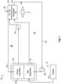
FIG. 1 is a schematic illustration of an embodiment of a cooling system for a power generation system; -
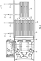
FIG. 2 is a partial cross-sectional view of an embodiment of a cooling system; -
FIG. 3 is a partial cross-sectional view of an embodiment of a cooling system operated in a first mode; -
FIG. 4 is a partial cross-sectional view of an embodiment of a cooling system operated in a second mode; and -
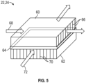
FIG. 5 is a partial view of an embodiment of a heat exchanger of a cooling system. - A detailed description of one or more embodiments of the disclosed apparatus and method are presented herein by way of exemplification and not limitation with reference to the Figures.
- Referring now to
FIG. 1 , an embodiment of acooling system 10 for a combined power generation andpower conversion apparatus 12 is illustrated. Theapparatus 12 includes agenerator 14, for example a permanent magnet generator. Thegenerator 14 generates electrical energy from, for example rotational energy imparted on thegenerator 14 by, for example, aturbine 16 or other power source. Apower converter 18, such as an active rectifier in one embodiment, which converts the electrical energy from thegenerator 14 into electrical power useful to one or more systems of the aircraft. Thepower converter 18 is connected to thegenerator 14, and in some embodiments is included in acommon housing 20 with thegenerator 14 to define an integrated combined power generation andpower conversion apparatus 12. - As shown in
FIG. 1 , thecooling system 10 is fluidly connected to thegenerator 14 and thepower converter 18 to cool thegenerator 14 and thepower converter 18. Thecooling system 10 includes agenerator heat exchanger 22 and a powerconverter heat exchanger 24 serially arranged such that anairflow 26 is directed first through the powerconverter heat exchanger 24 and then through thegenerator heat exchanger 22. In some embodiments, such as shown inFIG. 2 , the powerconverter heat exchanger 24 and thegenerator heat exchanger 22 are arranged in acommon duct 28 and afan 30 urges theairflow 26 across the powerconverter heat exchanger 24 and thegenerator heat exchanger 22. Referring again toFIG. 1 , agenerator cooling circuit 32 is defined between thegenerator heat exchanger 22 and thegenerator 14, circulating a flow ofgenerator coolant 34, such as oil, therethrough. The flow ofgenerator coolant 34 is circulated through thegenerator cooling circuit 32 via agenerator cooling pump 36. The flow ofgenerator coolant 34 is directed toward thegenerator 14 and absorbs thermal energy from thegenerator 14. The flow ofgenerator coolant 34 is then directed through thegenerator heat exchanger 22 where the thermal energy is rejected via theairflow 26. In some embodiments, thegenerator coolant 34 enters thegenerator 14 at an inlet temperature in the range of 85 to 95 degrees Celsius, and leaves thegenerator 14 at an exit temperature in the range of 100 to 115 degrees Celsius. - A power converter cooling circuit 38 is defined between the power
converter heat exchanger 24 and thepower converter 18, circulating a flow ofpower converter coolant 40, such as refrigerant, or a water based glycol coolant, therethrough. The flow ofpower converter coolant 40 is circulated through the power converter cooling circuit 38 via a powerconverter cooling pump 42. The flow ofpower converter coolant 40 is directed toward thepower converter 18 and absorbs thermal energy from thepower converter 18. The flow ofpower converter coolant 40 is then directed through the powerconverter heat exchanger 24 where the thermal energy is rejected via theairflow 26. In some embodiments, thepower converter coolant 40 enters thepower converter 18 at an inlet temperature in the range of 65 to 75 degrees Celsius, and leaves thepower converter 18 at an exit temperature in the range of 80 to 90 degrees Celsius. - Referring now to
FIG. 2 , thecooling system 10 is further illustrated. The powerconverter heat exchanger 24 and thegenerator heat exchanger 22 are located in theduct 28, with thefan 30 located at an upstream end of theduct 28, relative to the direction of theairflow 26 along theduct 28. The powerconverter heat exchanger 24 is located upstream of thegenerator heat exchanger 22, due to the greater cooling requirements of the powerconverter heat exchanger 24. Thepower converter coolant 40 enters the powerconverter heat exchanger 24 at a power converterheat exchanger inlet 46 and exits the powerconverter heat exchanger 24 at a power converterheat exchanger outlet 48. Similarly, thegenerator coolant 34 enters thegenerator heat exchanger 22 at a generatorheat exchanger inlet 50 and exits thegenerator heat exchanger 22 at a generatorheat exchanger outlet 52. Coolingfan 30 can be placed either upstream or downstream of the heat exchangers. - Referring now to
FIG. 3 , in some embodiments, thecooling system 10 may be operated in multiple modes. Thecooling system 10 includes afan door 54 located at, for example, afan outlet 56 of thefan 30, and aRAM air door 58 located in theduct 28 between thefan 30 and the powerconverter heat exchanger 24. In a first mode, as illustrated inFIG. 3 , theRAM air door 58 is in the closed position, and thefan door 54 is in the opened position. In this mode, thefan 30 is operated to urgeairflow 26 across the powerconverter heat exchanger 24 and thegenerator heat exchanger 22. This mode may be used when, for example, the aircraft is stationary on the ground. - In another mode, as illustrated in
FIG. 4 , thefan door 54 is in the closed position and theRAM air door 58 is in the opened position. In this mode,RAM airflow 26 is urged into the duct 44 through theRAM air door 58, and through the powerconverter heat exchanger 24 and thegenerator heat exchanger 22. This mode is used when, for example, the aircraft is in flight or otherwise when sufficient RAM airflow is present. - Referring to
FIG. 5 , in some embodiments theheat exchangers sheets 64. Each of the liquid flow layers 60 includes a plurality ofliquid side fins 66 extending in aliquid flow direction 68 along theliquid flow layer 60. Similarly, the air flow layers 62 each include a plurality of air side fins 70 extending in theair flow direction 72 along theair flow layer 62. In an exemplary powerconverter heat exchanger generator heat exchanger 22, 6 liquid flow layers 60 are stacked with 12 air flow layers 62. Each of the liquid flow layers 60 have a fin pitch of 24 fins per inch, while the air flow layers 62 each have a fin pitch of 16 fins per inch. Generally, due at least in part to the greater cooling requirements of thepower converter 18 relative to thegenerator 14, the powerconverter heat exchanger 24 is larger and has thusgreater airflow 26 therethrough, relative to thegenerator heat exchanger 22. - The configurations disclosed herein allows for improved cooling of the
power converter 18, thus improving reliability of thepower converter 18. Integration of the powerconverter heat exchanger 24 and thegenerator heat exchanger 22, which are each optimized to cool thepower converter 18 and the generator, 14, respectively, allows for improved performance of thecooling system 10 and further providing a potential weight savings from thecooling system 10. - The term "about" is intended to include the degree of error associated with measurement of the particular quantity based upon the equipment available at the time of filing the application.
- The terminology used herein is for the purpose of describing particular embodiments only and is not intended to be limiting of the present disclosure. As used herein, the singular forms "a", "an" and "the" are intended to include the plural forms as well, unless the context clearly indicates otherwise. It will be further understood that the terms "comprises" and/or "comprising," when used in this specification, specify the presence of stated features, integers, steps, operations, elements, and/or components, but do not preclude the presence or addition of one or more other features, integers, steps, operations, element components, and/or groups thereof.
- While the present disclosure has been described with reference to an exemplary embodiment or embodiments, it will be understood by those skilled in the art that various changes may be made and equivalents may be substituted for elements thereof without departing from the scope of the present disclosure. In addition, many modifications may be made to adapt a particular situation or material to the teachings of the present disclosure without departing from the essential scope thereof. Therefore, it is intended that the present disclosure not be limited to the particular embodiment disclosed as the best mode contemplated for carrying out this present disclosure, but that the present disclosure will include all embodiments falling within the scope of the claims.
Claims (11)
- A cooling system (10) of a power generation system, comprising:a generator cooling circuit (32) having a first cooling fluid circulating therethrough, the generator cooling circuit including a generator heat exchanger (22) fluidly connected to a generator of the power generation system via the generator cooling circuit to cool the generator; anda power converter cooling circuit (38) having a second cooling fluid different from the first cooling fluid circulating therethrough, the power converter cooling circuit including a power converter heat exchanger (24) fluidly connected to a power converter of the power generation system via the power converter cooling circuit to cool the power converter.
- The cooling system of claim 1, further comprising a common duct (28) in which the generator heat exchanger (22) and the power converter heat exchanger (24) are disposed.
- The cooling system of claim 2, wherein the power converter heat exchanger (24) is positioned fluidly upstream of the generator heat exchanger (22) relative to an airflow directed through the duct (28) to remove thermal energy from the power converter heat exchanger and the generator heat exchanger.
- The cooling system of claim 2 or 3, wherein the duct (28) is configured such that the airflow directed through the duct first flows through the power converter heat exchanger (24) and then through the generator heat exchanger (22).
- The cooling system of any of claims 2 to 4, further comprising a RAM air door (58) positioned in the duct (28) to selectably direct a RAM airflow through the duct.
- The cooling system of any of claims 2 to 5, further comprising a fan (30) positioned in the duct (28) to selectably direct the airflow from the fan through the duct.
- The cooling system of any preceding claim, wherein one or more of the generator heat exchanger (24) and the power converter heat exchanger (22) are plate and fin heat exchangers.
- The cooling system of any preceding claim, wherein the first cooling fluid is an oil.
- The cooling system of any preceding claim, wherein the second cooling fluid is a refrigerant, or water glycol mixture.
- The cooling system of any preceding claim, wherein the first cooling fluid is delivered to the generator at a first temperature, and the second cooling fluid is delivered to the power converter at a second temperature lower than the first temperature.
- A power generation system of an aircraft, comprising:an electrical generator (14);a power converter (18) operably connected to the electrical generator; anda cooling system (10) as claimed in any preceding claim, whereinthe generator heat exchanger (22) is fluidly connected to the electrical generator via the generator cooling circuit to cool the electrical generator; andthe power converter heat exchanger (24) is fluidly connected to the power converter via the power converter cooling circuit to cool the power converter.
Applications Claiming Priority (1)
| Application Number | Priority Date | Filing Date | Title |
|---|---|---|---|
| US17/725,769 US12166405B2 (en) | 2022-04-21 | 2022-04-21 | Power generator cooling system |
Publications (1)
| Publication Number | Publication Date |
|---|---|
| EP4266555A1 true EP4266555A1 (en) | 2023-10-25 |
Family
ID=86053963
Family Applications (1)
| Application Number | Title | Priority Date | Filing Date |
|---|---|---|---|
| EP23168483.8A Pending EP4266555A1 (en) | 2022-04-21 | 2023-04-18 | Power generator cooling system |
Country Status (2)
| Country | Link |
|---|---|
| US (1) | US12166405B2 (en) |
| EP (1) | EP4266555A1 (en) |
Citations (3)
| Publication number | Priority date | Publication date | Assignee | Title |
|---|---|---|---|---|
| US5271248A (en) * | 1991-08-23 | 1993-12-21 | Sundstrand Corporation | Dual cooling system |
| EP3144623A2 (en) * | 2015-09-21 | 2017-03-22 | Hamilton Sundstrand Corporation | Heat exchanger and cooling system for generator electronics cooling |
| EP3537578A1 (en) * | 2018-03-09 | 2019-09-11 | Hamilton Sundstrand Corporation | Variable speed constant frequency (vscf) generator system |
Family Cites Families (8)
| Publication number | Priority date | Publication date | Assignee | Title |
|---|---|---|---|---|
| ATE547604T1 (en) | 2009-06-26 | 2012-03-15 | Siemens Ag | COOLING CIRCUIT FOR REMOVING WASTE HEAT OF AN ELECTROMECHANICAL CONVERTER AND POWER PLANT WITH SUCH A COOLING CIRCUIT |
| EP2653386B1 (en) | 2012-04-17 | 2014-12-10 | Airbus Operations GmbH | Heat dissipation of power electronics of a cooling unit |
| US20150233265A1 (en) | 2012-08-10 | 2015-08-20 | youWINenergy GmbH | Integrated cooling system for a nacelle of a wind turbine |
| US9546589B2 (en) | 2012-11-05 | 2017-01-17 | General Electric Company | Integrated cooling system and method for engine-powered unit |
| US11255215B2 (en) * | 2017-07-06 | 2022-02-22 | Rolls-Royce North American Technologies Inc. | Gas turbine engine with microchannel cooled electric device |
| EP3907393B1 (en) | 2020-05-06 | 2024-04-03 | Hamilton Sundstrand Corporation | Thermal management system and method of use |
| US11912427B2 (en) | 2020-05-15 | 2024-02-27 | Hamilton Sundstrand Corporation | Thermal management system and method of use |
| US11878812B2 (en) * | 2022-03-23 | 2024-01-23 | Rolls-Royce Corporation | Aircraft accessory unit powered by ram air turbine |
-
2022
- 2022-04-21 US US17/725,769 patent/US12166405B2/en active Active
-
2023
- 2023-04-18 EP EP23168483.8A patent/EP4266555A1/en active Pending
Patent Citations (3)
| Publication number | Priority date | Publication date | Assignee | Title |
|---|---|---|---|---|
| US5271248A (en) * | 1991-08-23 | 1993-12-21 | Sundstrand Corporation | Dual cooling system |
| EP3144623A2 (en) * | 2015-09-21 | 2017-03-22 | Hamilton Sundstrand Corporation | Heat exchanger and cooling system for generator electronics cooling |
| EP3537578A1 (en) * | 2018-03-09 | 2019-09-11 | Hamilton Sundstrand Corporation | Variable speed constant frequency (vscf) generator system |
Non-Patent Citations (1)
| Title |
|---|
| KILGER: "HEAT TRANSFER MEDIA : AtoZ", 12 May 2015 (2015-05-12), XP093078013, Retrieved from the Internet <URL:https://web.archive.org/web/20150512134941/https://www.thermopedia.com/content/842/> [retrieved on 20230901] * |
Also Published As
| Publication number | Publication date |
|---|---|
| US12166405B2 (en) | 2024-12-10 |
| US20230344310A1 (en) | 2023-10-26 |
Similar Documents
| Publication | Publication Date | Title |
|---|---|---|
| US7334422B2 (en) | Cabin air conditioning system with liquid cooling for power electronics | |
| EP3144623B1 (en) | Heat exchanger and cooling system for generator electronics cooling | |
| US12054254B2 (en) | Method and system for cooling electronics in an unmanned aerial vehicle | |
| CA2949703A1 (en) | Method and system for pre-cooler exhaust energy recovery | |
| EP3628598B1 (en) | Power converter cooling | |
| EP3102013B1 (en) | System and method of alternate cooling of a liquid cooled motor controller | |
| EP3054126A1 (en) | Heat exchangers for thermal management systems | |
| US11255215B2 (en) | Gas turbine engine with microchannel cooled electric device | |
| EP4175130B1 (en) | Aircraft electric motor with integrated cooling system | |
| US11165309B2 (en) | Motor cooling system and method | |
| US12166405B2 (en) | Power generator cooling system | |
| EP3907393B1 (en) | Thermal management system and method of use | |
| US20230041836A1 (en) | Thermal management device and method of use | |
| EP4417515A1 (en) | Cabin air compressor auxiliary water cooling system | |
| EP3745833B1 (en) | Aircraft power electronic unit and method of cooling | |
| EP4513121A1 (en) | Multi-mode cooling method for heat source and a respective system | |
| EP3985844A1 (en) | Laminated stator with cooling lamination layers | |
| EP4339434B1 (en) | Air-cooling system | |
| US20230301042A1 (en) | Combined liquid and air cooled power electronics assembly | |
| EP4016815A1 (en) | Two-phase thermal management system with active control for high density electric machine | |
| EP3910177A1 (en) | Thermal management system and method of use | |
| EP4585879A2 (en) | Feature for subfreezing heat exchanger |
Legal Events
| Date | Code | Title | Description |
|---|---|---|---|
| STAA | Information on the status of an ep patent application or granted ep patent |
Free format text: STATUS: THE APPLICATION HAS BEEN PUBLISHED |
|
| PUAI | Public reference made under article 153(3) epc to a published international application that has entered the european phase |
Free format text: ORIGINAL CODE: 0009012 |
|
| AK | Designated contracting states |
Kind code of ref document: A1 Designated state(s): AL AT BE BG CH CY CZ DE DK EE ES FI FR GB GR HR HU IE IS IT LI LT LU LV MC ME MK MT NL NO PL PT RO RS SE SI SK SM TR |
|
| STAA | Information on the status of an ep patent application or granted ep patent |
Free format text: STATUS: REQUEST FOR EXAMINATION WAS MADE |
|
| 17P | Request for examination filed |
Effective date: 20240424 |
|
| RBV | Designated contracting states (corrected) |
Designated state(s): AL AT BE BG CH CY CZ DE DK EE ES FI FR GB GR HR HU IE IS IT LI LT LU LV MC ME MK MT NL NO PL PT RO RS SE SI SK SM TR |
|
| STAA | Information on the status of an ep patent application or granted ep patent |
Free format text: STATUS: EXAMINATION IS IN PROGRESS |
|
| 17Q | First examination report despatched |
Effective date: 20250526 |