EP4266538A2 - Robotic tool and charging station - Google Patents
Robotic tool and charging station Download PDFInfo
- Publication number
- EP4266538A2 EP4266538A2 EP23168751.8A EP23168751A EP4266538A2 EP 4266538 A2 EP4266538 A2 EP 4266538A2 EP 23168751 A EP23168751 A EP 23168751A EP 4266538 A2 EP4266538 A2 EP 4266538A2
- Authority
- EP
- European Patent Office
- Prior art keywords
- charging
- base
- charging station
- tool
- positive electrode
- Prior art date
- Legal status (The legal status is an assumption and is not a legal conclusion. Google has not performed a legal analysis and makes no representation as to the accuracy of the status listed.)
- Pending
Links
Images




Classifications
-
- B—PERFORMING OPERATIONS; TRANSPORTING
- B60—VEHICLES IN GENERAL
- B60L—PROPULSION OF ELECTRICALLY-PROPELLED VEHICLES; SUPPLYING ELECTRIC POWER FOR AUXILIARY EQUIPMENT OF ELECTRICALLY-PROPELLED VEHICLES; ELECTRODYNAMIC BRAKE SYSTEMS FOR VEHICLES IN GENERAL; MAGNETIC SUSPENSION OR LEVITATION FOR VEHICLES; MONITORING OPERATING VARIABLES OF ELECTRICALLY-PROPELLED VEHICLES; ELECTRIC SAFETY DEVICES FOR ELECTRICALLY-PROPELLED VEHICLES
- B60L53/00—Methods of charging batteries, specially adapted for electric vehicles; Charging stations or on-board charging equipment therefor; Exchange of energy storage elements in electric vehicles
- B60L53/30—Constructional details of charging stations
- B60L53/35—Means for automatic or assisted adjustment of the relative position of charging devices and vehicles
-
- H—ELECTRICITY
- H02—GENERATION; CONVERSION OR DISTRIBUTION OF ELECTRIC POWER
- H02J—ELECTRIC POWER NETWORKS; CIRCUIT ARRANGEMENTS OR SYSTEMS FOR SUPPLYING OR DISTRIBUTING ELECTRIC POWER; SYSTEMS FOR STORING ELECTRIC ENERGY
- H02J7/00—Circuit arrangements for charging or discharging batteries or for supplying loads from batteries
- H02J7/70—Circuit arrangements for charging or discharging batteries or for supplying loads from batteries characterised by the mechanical construction
-
- H—ELECTRICITY
- H01—ELECTRIC ELEMENTS
- H01R—ELECTRICALLY-CONDUCTIVE CONNECTIONS; STRUCTURAL ASSOCIATIONS OF A PLURALITY OF MUTUALLY-INSULATED ELECTRICAL CONNECTING ELEMENTS; COUPLING DEVICES; CURRENT COLLECTORS
- H01R13/00—Details of coupling devices of the kinds covered by groups H01R12/70 or H01R24/00 - H01R33/00
- H01R13/66—Structural association with built-in electrical component
- H01R13/70—Structural association with built-in electrical component with built-in switch
- H01R13/703—Structural association with built-in electrical component with built-in switch operated by engagement or disengagement of coupling parts, e.g. dual-continuity coupling part
-
- A—HUMAN NECESSITIES
- A01—AGRICULTURE; FORESTRY; ANIMAL HUSBANDRY; HUNTING; TRAPPING; FISHING
- A01D—HARVESTING; MOWING
- A01D34/00—Mowers; Mowing apparatus of harvesters
- A01D34/006—Control or measuring arrangements
- A01D34/008—Control or measuring arrangements for automated or remotely controlled operation
-
- A—HUMAN NECESSITIES
- A01—AGRICULTURE; FORESTRY; ANIMAL HUSBANDRY; HUNTING; TRAPPING; FISHING
- A01D—HARVESTING; MOWING
- A01D34/00—Mowers; Mowing apparatus of harvesters
- A01D34/01—Mowers; Mowing apparatus of harvesters characterised by features relating to the type of cutting apparatus
- A01D34/412—Mowers; Mowing apparatus of harvesters characterised by features relating to the type of cutting apparatus having rotating cutters
- A01D34/63—Mowers; Mowing apparatus of harvesters characterised by features relating to the type of cutting apparatus having rotating cutters having cutters rotating about a vertical axis
- A01D34/76—Driving mechanisms for the cutters
- A01D34/78—Driving mechanisms for the cutters electric
-
- B—PERFORMING OPERATIONS; TRANSPORTING
- B60—VEHICLES IN GENERAL
- B60L—PROPULSION OF ELECTRICALLY-PROPELLED VEHICLES; SUPPLYING ELECTRIC POWER FOR AUXILIARY EQUIPMENT OF ELECTRICALLY-PROPELLED VEHICLES; ELECTRODYNAMIC BRAKE SYSTEMS FOR VEHICLES IN GENERAL; MAGNETIC SUSPENSION OR LEVITATION FOR VEHICLES; MONITORING OPERATING VARIABLES OF ELECTRICALLY-PROPELLED VEHICLES; ELECTRIC SAFETY DEVICES FOR ELECTRICALLY-PROPELLED VEHICLES
- B60L53/00—Methods of charging batteries, specially adapted for electric vehicles; Charging stations or on-board charging equipment therefor; Exchange of energy storage elements in electric vehicles
- B60L53/10—Methods of charging batteries, specially adapted for electric vehicles; Charging stations or on-board charging equipment therefor; Exchange of energy storage elements in electric vehicles characterised by the energy transfer between the charging station and the vehicle
- B60L53/14—Conductive energy transfer
- B60L53/16—Connectors, e.g. plugs or sockets, specially adapted for charging electric vehicles
-
- B—PERFORMING OPERATIONS; TRANSPORTING
- B60—VEHICLES IN GENERAL
- B60L—PROPULSION OF ELECTRICALLY-PROPELLED VEHICLES; SUPPLYING ELECTRIC POWER FOR AUXILIARY EQUIPMENT OF ELECTRICALLY-PROPELLED VEHICLES; ELECTRODYNAMIC BRAKE SYSTEMS FOR VEHICLES IN GENERAL; MAGNETIC SUSPENSION OR LEVITATION FOR VEHICLES; MONITORING OPERATING VARIABLES OF ELECTRICALLY-PROPELLED VEHICLES; ELECTRIC SAFETY DEVICES FOR ELECTRICALLY-PROPELLED VEHICLES
- B60L53/00—Methods of charging batteries, specially adapted for electric vehicles; Charging stations or on-board charging equipment therefor; Exchange of energy storage elements in electric vehicles
- B60L53/30—Constructional details of charging stations
-
- H—ELECTRICITY
- H01—ELECTRIC ELEMENTS
- H01R—ELECTRICALLY-CONDUCTIVE CONNECTIONS; STRUCTURAL ASSOCIATIONS OF A PLURALITY OF MUTUALLY-INSULATED ELECTRICAL CONNECTING ELEMENTS; COUPLING DEVICES; CURRENT COLLECTORS
- H01R13/00—Details of coupling devices of the kinds covered by groups H01R12/70 or H01R24/00 - H01R33/00
- H01R13/02—Contact members
-
- H—ELECTRICITY
- H01—ELECTRIC ELEMENTS
- H01R—ELECTRICALLY-CONDUCTIVE CONNECTIONS; STRUCTURAL ASSOCIATIONS OF A PLURALITY OF MUTUALLY-INSULATED ELECTRICAL CONNECTING ELEMENTS; COUPLING DEVICES; CURRENT COLLECTORS
- H01R13/00—Details of coupling devices of the kinds covered by groups H01R12/70 or H01R24/00 - H01R33/00
- H01R13/02—Contact members
- H01R13/03—Contact members characterised by the material, e.g. plating, or coating materials
-
- H—ELECTRICITY
- H01—ELECTRIC ELEMENTS
- H01R—ELECTRICALLY-CONDUCTIVE CONNECTIONS; STRUCTURAL ASSOCIATIONS OF A PLURALITY OF MUTUALLY-INSULATED ELECTRICAL CONNECTING ELEMENTS; COUPLING DEVICES; CURRENT COLLECTORS
- H01R13/00—Details of coupling devices of the kinds covered by groups H01R12/70 or H01R24/00 - H01R33/00
- H01R13/40—Securing contact members in or to a base or case; Insulating of contact members
-
- H—ELECTRICITY
- H02—GENERATION; CONVERSION OR DISTRIBUTION OF ELECTRIC POWER
- H02J—ELECTRIC POWER NETWORKS; CIRCUIT ARRANGEMENTS OR SYSTEMS FOR SUPPLYING OR DISTRIBUTING ELECTRIC POWER; SYSTEMS FOR STORING ELECTRIC ENERGY
- H02J7/00—Circuit arrangements for charging or discharging batteries or for supplying loads from batteries
- H02J7/70—Circuit arrangements for charging or discharging batteries or for supplying loads from batteries characterised by the mechanical construction
- H02J7/751—Circuit arrangements for charging or discharging batteries or for supplying loads from batteries characterised by the mechanical construction concerning the insertion or the connection of the batteries
-
- A—HUMAN NECESSITIES
- A01—AGRICULTURE; FORESTRY; ANIMAL HUSBANDRY; HUNTING; TRAPPING; FISHING
- A01D—HARVESTING; MOWING
- A01D2101/00—Lawn-mowers
-
- B—PERFORMING OPERATIONS; TRANSPORTING
- B60—VEHICLES IN GENERAL
- B60L—PROPULSION OF ELECTRICALLY-PROPELLED VEHICLES; SUPPLYING ELECTRIC POWER FOR AUXILIARY EQUIPMENT OF ELECTRICALLY-PROPELLED VEHICLES; ELECTRODYNAMIC BRAKE SYSTEMS FOR VEHICLES IN GENERAL; MAGNETIC SUSPENSION OR LEVITATION FOR VEHICLES; MONITORING OPERATING VARIABLES OF ELECTRICALLY-PROPELLED VEHICLES; ELECTRIC SAFETY DEVICES FOR ELECTRICALLY-PROPELLED VEHICLES
- B60L2200/00—Type of vehicles
- B60L2200/40—Working vehicles
Definitions
- the embodiments described herein related to a robotic garden tool, and more specifically to a charging station for use with the robotic garden tool.
- Robot tools are typically used with some form of charging station to allow the tool to recharge any internal batteries from time to time.
- a charging station for use with a robotic garden tool, the charging station including a base having an upper surface and a lower surface, the lower surface of the base being configured to be supported on a support surface, a charging terminal coupled to the upper surface of the base, where the charging terminal includes a positive electrode and a ground electrode electrically insulated from the positive electrode, where the positive electrode and the ground electrode are configured to selectively extend upward to a location vertically above the upper surface of the base.
- the charging terminal is convex and includes a flexible material to permit deformation of the convex charging terminal.
- the charging terminal includes an outer portion, an intermediate portion and a central portion, the outer portion substantially encircling the intermediate portion, and the intermediate portion substantially encircling the central portion, where the outer portion and the central portion are formed from a conductive material and where the intermediate portion is formed from an insulating material.
- the charging terminal includes a plurality of radially nested portions.
- the charging terminal includes a moveable member configured to move from a first position in which the moveable member is near the upper surface of the base and a second position in which the moveable member extends vertically above the upper surface of the base, where at least a portion of the moveable member is formed from a conductive material.
- the moveable member is configured to pivot between the first position and the second position.
- the charging terminal includes a first moveable member configured to move from a first position in which the first moveable member is near the upper surface of the base and a second position in which the first moveable member extends vertically above the upper surface of the base, at least a portion of the first moveable member is formed from a conductive material, and a second moveable member configured to move from a first position in which the second moveable member is near the upper surface of the base and a second position in which the second moveable member extends vertically above the upper surface of the base, at least a portion of the second moveable member is formed from a conductive material.
- a robotic garden tool including a body having a front end, a rear end opposite the front end, an upper surface and a lower surface opposite the upper surface, one or more driven wheels mounted to the body, a working tool mounted to the body, a battery, and a charging port open to the lower surface of the body, the charging port including a positive electrode and a ground electrode that is electronically isolated from the positive electrode.
- the charging port is positioned between the front end and the working tool.
- the charging port is concave such that the positive and ground electrodes extend into the body.
- the charging port includes an outer portion, an intermediate portion and a central portion, the outer portion substantially encircling the intermediate portion, and the intermediate portion substantially encircling the central portion, where the outer portion and the central portion are formed from a conductive material and where the intermediate portion is formed from an insulating material.
- the charging port includes a plurality of radially nested portions.
- the charging port includes a contact coupled to a flexible member, the flexible member permitting limited vertical movement of the contact with respect to the body, the flexible member retaining the contact near the lower surface of the body, where at least a portion of the contact is formed from a conductive material.
- the charging port further comprising a second contact coupled to a second flexible member, the second flexible member permitting limited vertical movement of the second contact with respect to the body, the second flexible member retaining the second contact near the lower surface of the body, where at least a portion of the second contact is formed from a conductive material.
- a robotic garden tool kit including a charging station including a base having an upper surface and a lower surface, the lower surface of the base being configured to be supported on a support surface, and a charging terminal coupled to the upper surface of the base, where the charging terminal includes a positive electrode and a ground electrode, and a robotic garden tool.
- the robotic garden tool includes a body having an upper surface and a lower surface opposite the upper surface, one or more driven wheels mounted to the body, a working tool mounted to the body, a battery, and a charging port including a positive electrode positioned near the lower surface of the body, and a ground electrode positioned near the lower surface of the body, where the robotic garden tool is configured to move to a location above the charging terminal, such that while the charging port is positioned vertically above the charging terminal, the positive electrode of the base is in electrical communication with the positive electrode of the of the charging terminal is in electrical contact with the positive electrode of the charging port, and the ground electrode of the charging terminal is in electrical contact with the ground electrode of the charging port.
- the charging terminal is convex and includes a flexible material to permit downward deformation of the convex charging terminal
- the body has a front end and a rear end opposite the front end, where the charging port is positioned between the front end and the working tool, and where the charging port is concave such that an outer portion of the charging port is connected to the lower surface of the body and an inner portion of the charging port is recessed above the lower surface of the body.
- the charging terminal includes an outer portion, an intermediate portion and a central portion, the outer portion substantially encircling the intermediate portion, and the intermediate portion substantially encircling the central portion, where the outer portion and the central portion are formed from a conductive material and where the intermediate portion is formed from an insulating material
- the charging port includes an outer portion, an intermediate portion and a central portion, the outer portion substantially encircling the intermediate portion, and the intermediate portion substantially encircling the central portion, where the outer portion and the central portion are formed from a conductive material and where the intermediate portion is formed from an insulating material.
- the charging port includes a contact coupled to a flexible member, the flexible member permitting limited vertical movement of the contact with respect to the body, the flexible member retaining the contact near the lower surface of the body, where at least a portion of the contact is formed from a conductive material
- the charging terminal includes a moveable member configured to move from a first position in which the moveable member is near the upper surface of the base and a second position in which the moveable member extends vertically above the upper surface of the base, and where at least a portion of the moveable member is formed from a conductive material.
- the moveable member is configured to pivot between the first position and the second position in response to the charging port being positioned vertically above the charging terminal.
- the charging port of the charging station is configured to supply a first charge while the robotic garden tool is spaced from the charging station, and is configured to supply a second charge while the robotic garden tool is positioned above the charging station, the second charge being greater than the first charge.
- any combination further comprising a cleaning element positioned on one of the charging station and the robotic garden tool, the cleaning element configured to remove debris from the charging port while the robotic garden tool is positioned vertically above the charging station.
- a charging station for use with a robotic garden tool, the charging station including a base, and a charging terminal coupled to the base, where the charging terminal includes a positive electrode and a ground electrode electrically insulated from the positive electrode, wherein the charging terminal is convex.
- the positive electrode and the ground electrode are formed from conductive material and wherein the intermediate portion is formed from an insulating material.
- the charging terminal includes an outer portion, the intermediate portion and a central portion, the outer portion substantially encircling the intermediate portion, and the intermediate portion substantially encircling the central portion.
- the outer portion forms one of the ground electrode and the positive electrode and where the central portion forms the other of the ground electrode and the positive electrode.
- charging terminal is resiliently deformable.
- FIGS 1-3 illustrate a robotic garden tool 10. More specifically, the garden tool 10 includes a robotic lawn mower for use to cut vegetation such as grass in an enclosed cutting area 14.
- the cutting area 14 generally includes, but is not limited to, a continuous area of grass or other vegetation that is enclosed by one or more barriers 16.
- the barriers 16 include a series of electrified wires enclosing the cutting area 14 while in alternative embodiments different form of barrier may be used such as, but not limited to, walls, pavers, GPS data points, and the like. As shown in FIG. 1 , such barriers 16 may be used to enclose the overall cutting area 14 and/or to segregate one or more interior regions from the cutting area 14. While the illustrated tool 10 is a robotic mower, it is understood that in alternative embodiments other forms of robotic tool may be used including, but not limited to, a robotic trimmer, a robotic sprinkler, a robotic fertilizer spreader, and the like.
- the tool 10 is an electrically powered, self-propelled device that includes a body 18, a plurality of wheels 22 rotatably mounted to the body 18, a working tool 26 mounted to the body 18, a guard 28 extending around the working tool 26, a controller 30, a battery 32, and a charging port 80.
- the body 18 also defines a longitudinal axis 50 extending along the length of the body 18 and centered between the first side 42 and the second side 44 (e.g., passing through both the first and second ends 34, 38).
- the body 18 also defines a lateral axis 54 extending along the width of the body 18 and centered between the first and second ends 34, 38 (e.g., passing through both the first and second sides 42, 44).
- the body 18 also defines a central axis 58 generally positioned at the intersection of the longitudinal and lateral axes 50, 54 and oriented perpendicular to both (e.g., in a generally vertical orientation).
- the tool 10 includes four wheels 22a, 22b, 22c, 22d, each rotatably coupled to the body 18 and configured to support the tool 10 for self-driven movement along a support surface 60 (e.g., the surface of the cutting area 14).
- the wheels 22a, 22b, 22c, 22d include two steerable, undriven wheels 22a, 22b and two non-steerable, driven wheels 22c, 22d.
- all or any sub-set of the wheels 22 may be driven and all or any sub-set of the wheels 22 may be steerable.
- steerable wheels are passive in nature (e.g., a caster-style wheel), it is understood that in alternative embodiments the steerable wheels 22a, 22b may be actively driven by the controller 30.
- the tool 10 may include more or fewer wheels 22 positioned in different arrangements about the tool 10.
- the wheels 22 may be replaced by other forms of propulsion such as, but not limited to, tracks, omni-wheels, walking legs, and the like.
- the working tool 26 includes a rotating blade mounted for relative rotation about a blade axis 72. More specifically, the blade 26 is mounted to a dedicated blade motor 76 which rotates the blade 26 during use.
- the blade axis 72 is oriented vertically (e.g., parallel to the central axis 58) and positioned proximate the center of the body 18. In some embodiments, the blade axis 72 may be coincident with the central axis 58.
- the illustrated working tool 26 is a rotating blade, it is understood that in alternative embodiments the tool 10 may include, but is not limited to, reciprocating blades, a distributor or dispenser of some kind, and the like.
- the tool 10 is configured to travel in a direction V during operation.
- the tool 10 also includes a charging port 80.
- the charging port 80 is in operable communication with at least the battery 32 of the tool 10 and configured to create a temporary electrical connection with a charging station 84 (described below) to convey the electrical energy output by the charging station 84 to the battery 32 for re-charging operations.
- the charging port 80 includes a concave recess formed into and open to the bottom surface 48 of the body 18 of the tool 10.
- the charging port 80 includes a central or first portion 88a, an outer or second portion 88c, and an intermediate portion 88b positioned between and electrically isolating the central portion 88a from the outer potion 88c.
- all three portions 88a, 88b, 88c are concentric resulting in a circular central portion 88a, an annular intermediate portion 88b, and an annular outer portion 88c.
- the illustrated charging port 80 is circular in overall shape, it is understood that in other embodiments different shapes of concentric portions be used including, but not limited to, elliptical, polygonal, and the like.
- the central and outer portions 88a, 88c of the charging port 80 are formed from conductive material (e.g., metal); forming a positive and ground electrode, respectively.
- the intermediate portion 88b is formed from an insulating material to electrically isolate the central portion 88a from the outer portion 88c.
- the central portion 88a may form the ground electrode while the outer portion 88c forms the positive electrode.
- the illustrated charging port 80 includes three portions forming a single set of electrodes (positive and ground and insulating buffer), it is understood that in alternative embodiments more concentric portions may be included to allow for additional circuits to be formed between the port 80 and the charging station 84. Such additional circuits may be used for, but are not limited to, data communication, docking verification, and the like.
- the charging port 80 is positioned between the first end 34 and the guard 28 of the working tool 26, being centered side-to-side along the lateral axis 54.
- the charging port 80 may be positioned in alternative positions on the bottom surface 48 of the tool 10 to best accommodate the docking process between the tool 10 and the charging station 84.
- the charging port 80 may be positioned between the second end 38 and the guard 28.
- the charging port 80' may be positioned adjacent and open to one of the ends 34, 38, 42, 44 of the body 18 of the tool.
- more than one charging port 80 may be present on a single body 18 to accommodate docking approaches from multiple directions and/or conditions.
- the charging station 84 includes a charging terminal 92 and a core or base 90 to support, position, and orient the charging terminal 92 relative to the support surface 60.
- the charging station 84 is electrically connected to a power source, such as a battery or an electrical outlet, whereby the charging station 84 is configured to provide an electrical mounting point to which the charging port 80 of the tool 10 can dock to allow for electrical communication therebetween.
- the base 90 of the charging station 84 has an upper surface 94 and a lower surface 96. Together, the upper surface 94 and the lower surface 96 produce a vertical base height configured to position the terminal 92 at a height substantially corresponding to the height of the underside 48 of the tool 10.
- the lower surface 96 can be supported on the support surface 60.
- the base 90 can be any suitable shape to accommodate the approach and docking between the tool 10 and the charging station 84. In the illustrated embodiment, the base 90 is sized to fit between the front wheels 22a, 22b of the tool 10. In other embodiments, the base 90 may include tapered sidewalls (e.g., narrowing in width as it extends radially outwardly) to help guide the tool 10 into alignment with the charging terminal 92.
- the base 90 may have beveled sidewalls (e.g., angled vertically downwardly) to allow the wheels 22 of the tool 10 to ride up onto and across the base 90.
- the base 90 may include one or more stakes extending therefrom (not shown) to allow the base 90 to be secured to a soft support surface 60 such as soil and the like.
- the base 90 may be attached to support surface or mat 100 (see FIG. 5 ) to provide additional support, for example on hard support surfaces 60 such a concrete and the like.
- the mat 100 may be wider than the tool 10, such that the tool 10 can be fully supported on the mat 100 during the docking process.
- the mat 100 is positioned directly on the support surface 60.
- different forms of support may be interchangeable to the base 90 so the user can accommodate the desired installation location. While the illustrated base 90 and mat 100 are described as separate elements, it is understood that in still other embodiments the base 90 and mat 100 may be formed integrally together as a single unit.
- the charging terminal 92 of the charging station 94 is sized and shaped to correspond with the size and shape of the charging port 80 of the tool 10 to form a temporary electrical connection therebetween.
- the charging terminal 92 is a convex, generally dome-shaped protrusion, extending from the upper surface 94 of the base 90.
- the terminal 92 includes a first or central portion 98a, a second or outer portion 98c, and an intermediate portion 98b extending between and electrically isolating the central portion 98a from the outer portion 98c.
- all three portion 98a, 98b, 98c are concentric having sizes and shapes that generally correspond to the sizes and shapes of the three portions 88a, 88b, 88c of the charging port 80. More specifically, the illustrated outer portion 98c encircles the intermediate portion 98b, and the illustrated intermediate portion 98b encircles the central portion 98a. Similar to the charging port 80, the intermediate portion 98b is formed from an insulating material while the central and outer portions 98a, 98c are formed from conductive material (e.g., metal). In the illustrated embodiments, the outer portion 98c is a positive electrode, and the central portion 98a is a ground electrode to mirror the layout of the charging port 80.
- the central portion 98a is the positive electrode and the outer portion 98c is the ground electrode.
- Other shapes, sizes and configurations of charging terminals can be utilized in other embodiments.
- the three portions 98a, 98b, 98c may include other nested shaped (e.g., rectangular, polygonal, and the like), parallel strips, and the like.
- At least a portion of the charging terminal 92 is made from a resilient, flexible material to permit deformation of the charging terminal 92 to accommodate the body 18 of the tool 10. More specifically, the dome shape of the charging terminal 92 causes the charging terminal 92 to act as a spring, whereby the terminal 92 will deform when subject to an external force (e.g., contacting the body 18 of the tool 10) and resiliently return to the original domed shape upon removal of the external force. This permits the terminal 92 to deform out of the way of the body 18 and resiliently expand up and into the charging port 80 once aligned therewith.
- the first end 34 of the tool 10 includes a resilient, deformable material that deforms in response to the first end 34 of the tool 10 moving across the charging terminal 92.
- the charging terminal 92 is sized to be at least partially received within the charging port 80 such that the central portions 88a, 98a form an electrical connection, and the outer portions 88c, 98c form an electrical connection.
- the charging station 84 is configured so that the tool 10 can approach the charging station 84 from any direction and the charging port 80 of the tool 10 and the charging terminal 92 of the charging station 84 can form an electrical connection.
- the tool 10 To dock the tool 10 to the charging terminal 92, the tool 10 first approaches the charging station 84 while traveling in a direction V. As stated above, the tool 10 may approach the charging station radially from any direction across a 360-degree arc.
- the first end 34 contacts the terminal 92 and begins to deform the terminal 92. More specifically, the first end 34 vertically compresses the terminal 92 such that the terminal 92 can pass below the body 18 while being in contact with the bottom surface 48 thereof. The terminal 92 then remains compressed below the body 18 until the terminal 92 becomes aligned with the charging port 80. Once aligned, the terminal 92 will resiliently expand back to its original configuration - expanding upwardly into the recess of the charging port 80. By doing so, the central and outer portions 98a, 98c of the terminal 92 come into contact and form an electrical connection with the central and outer portions 88a, 88c of the charging port 80 respectively. With the electrical connection made, the charging station 84 may then provide electrical power to the battery 32 of the tool 10 for the charging process.
- the tool 10 may disengage from the terminal 92. To do so, the tool 10 may travel in a second direction, opposite the direction V, whereby the terminal 92 is again compressed by the body 18 of the tool 10 so that it can pass underneath the bottom surface 48 thereof. After the tool 10 is no longer overlapping the terminal 92, the terminal 92 can resiliently expand back to its original dome-shaped configuration.
- the resiliency of the terminal 92 may permit the tool 10 to continue to travel in direction V after the charging process is complete. By doing so, the tool 10 does not need to turn or maneuver after the charging process.
- one or more ramps or moving members can raise the front end 34 of the tool 10 over the charging terminal 92 and then lower the tool 10 when the charging port 80 is generally aligned with the charging terminal 92.
- Such ramps can be used together with the resilient nature of the terminal 92 (e.g., so that less deformation is required to allow the terminal 92 to pass under the body 18), or in place of the resiliency (e.g., the vertical displacement produced by the ramps produce the necessary clearance for the terminal 92 to pass under the body 18).
- a switch and/or sensor may be coupled to the mat 100 to sense the presence of the tool 10. While the tool 10 is not positioned on the mat 100, the charging station 84 is configured to supply a first charge to the charging terminal 92. While the tool 10 is positioned on the mat 100, the charging station 84 is configured to provide a second charge to the charging terminal 92.
- the first charge is smaller, and in some cases, significantly smaller, than the second charge. In some embodiments, the first charge is between 0 and 30 volts, and the second charge is greater than 30 volts. In some embodiments, the first charge is between 0 and 20 volts, and the second charge is greater than 35 volts.
- the charging port 80' is in the shape of a half dome adjacent and open to one of the ends 34, 39, 42, 44 (see FIG. 2A ).
- the central portion 88a is a semi-circle that abuts the first end 34 of the tool 10
- the intermediate portion 88b and outer portion 88c extend in a semi-circular ring with each end abutting the first end 34 of the tool 10.
- the charging terminal 92 could still remain as a full dome to permit the tool 10 to approach the charging station 84 from any number of directions.
- the tool 10 is configured to depart from the charging station 84 in a different direction than it approached the charging station 84.
- debris such as grass clippings
- a blower can be activated by the presence of the tool 10 on or near the charging station 84.
- the blower can be angled upward to blow air into and across the charging port 80 prior to the charging terminal 92 extending into the charging port 80.
- a brush (not shown) may be coupled to the charging station 84, (i.e., extending upwardly from an upper surface of the mat 100) so that when the tool 10 approaches the charging station 84, the brush extends upwardly into at least a portion of the charging port 80. By doing so, the process of traveling over the brush causes the brush to wipe away any debris located within the charging port 80 prior to the charging terminal 92 extending into the charging port 80.
- Figs. 6 and 7 illustrate another embodiment of a tool 210 and a charging station 284.
- the tool 210 and charging station 284 are substantially similar to the tool 10 and charging station 84 described above. As such, only the differences will be discussed in detail herein.
- the charging port 280 of the tool 210 is in operable communication with at least the battery 232 of the tool 210 and configured to create a temporary electrical connection with a charging station 284 (described below) to convey the electrical energy output by the charging station 284 to the battery 232 for re-charging operations. More specifically, the illustrated charging port 280 includes a first electrode 286 and a second electrode 288.
- the first electrode 286 includes first contact 286a and a first flexible member 286b, and the second electrode 288 includes a second contact 288a and a second flexible member 288b.
- the first electrode 286 is a positive electrode and the second electrode 288 is a ground electrode. In other embodiments, the first electrode 286 is the ground electrode and second electrode 288 is the positive electrode.
- the flexible members 286b, 288b of the electrodes 286, 288 permit limited movement of the respective contacts 286a, 286a relative to the body 218.
- the flexible members 286b, 288b retaining the respective contact 286a, 288a in a rest position near the lower surface 248 of the body 218 until being biased away therefrom by an external force (e.g., contact with electrode 298, 302 of the docking station 284, described below).
- At least a portion of the first contact 286a, and a least a portion of the second contact 288a is formed from a conductive material.
- the illustrated charging port 280 is positioned between a front end of the body 218 and the guard 228. In some embodiments, the charging port 280 may be positioned between a rear end of the body 218 and the guard 228. Other shapes, sizes and configurations of charging ports can be utilized in other embodiments.
- the charging station 284 includes a base 290 and a charging terminal 292.
- the charging station 284 is configured to provide an electrical mounting point to which the charging port 280 of the tool 210 can dock to allow for temporary electrical communication therebetween.
- the base 290 of the charging station 284 includes an upper surface 294 and a lower surface 296. When installed, the lower surface 296 can be supported on a support surface 60 while the upper surface 294 is configured to support at least two of the wheels 222 of the tool 10 thereon.
- the base 290 may include a beveled edge or ramp to allow the wheels 222 of the tool 210 to drive up onto and traverse across the upper surface 294 of the base 290.
- the illustrated base 290 is larger than the tool 210, such that the tool 210 can be fully supported on the base 290. In still other embodiments, different forms of support may be interchangeable to the base 290 so the user can accommodate the desired installation location.
- the charging station 284 is electrically connected to a power source, such as a battery or an electrical outlet.
- the charging terminal 292 includes a first electrode 298 and a second electrode 302.
- the first electrode 298 is an elongate member movably coupled to the base 290 for pivoting about the base 290 between a first or stowed position (see FIG. 6 ) and a second or deployed position (see FIG. 7 ).
- the first or contact end of the first electrode 298 is positioned near or below the upper surface 294 of the base 290 (e.g., the first electrode 298 does not engage or make an electrical connection with a tool 210 positioned on the charging station 284) while in the second position, the contact end of the first electrode 298 extends vertically above the upper surface 294 of the base 290 (e.g., the first electrode 298 does engage and make an electrical connection with a tool 210 positioned on the charging station 284).
- the contact end of the first electrode 298 is formed from a conductive material.
- the second electrode 302 is an elongate member coupled to the base 290 for pivoting about the base 290 between a first or stowed position (see FIG. 6 ) and a second or deployed position (see FIG. 7 ).
- first or contact end of the second electrode 302 is positioned near or below the upper surface 294 of the base 290 (e.g., the second electrode 302 does not engage or make an electrical connection with a tool 210 positioned on the charging station 284)
- the contact end of the second electrode 302 extends vertically above the upper surface of the base 290 (e.g., the second electrode 302 does engage and form an electrical connection with a tool 210 positioned on the charging station 284).
- the contact end of the second electrode 201 is formed from a conductive material.
- the base 290 also includes a first moveable plate member 306 supported on a first biasing member and a second moveable plate member 308 supported on a second biasing member.
- the first and second moveable plate member 306, 308 are sized to each receive one of the wheels 222 thereon. More specifically, both movable plate members 306, 308 are movable relative to the base 290 between a rest position, in which the plate members 306, 308 are coplanar with the upper surface 294 of the base 290 (see FIG. 6 ), and a displaced position, in which the plate members 306, 308 are displaced below the upper surface 294 (see FIG. 7 ).
- the illustrated first biasing member is a pair of coil springs 310a, 31 0b
- the illustrated second biasing member is a pair of coil springs 312a, 312b.
- Other biasing members could be used in place of or in addition to the illustrated coil springs.
- the first moveable plate member 306 is coupled to a second end of the first electrode 298 so that vertical movement of the first movable plate member 306 between the rest and displaced positions causes the first electrode 284 to pivot between the stowed and deployed positions. More specifically, the first movable plate member 306 is configured so that the first electrode 284 is in the stowed position when the plate 306 is in the rest position (see FIG. 6 ), and wherein moving the plate member 306 toward the displaced position causes the first electrode 284 to pivot from the stowed position toward the deployed position (see FIG. 7 ).
- the second moveable plate member 308 is coupled to a second end of the second electrode 302 so that vertical movement of the second movable plate member 308 between the rest and displaced positions causes the second electrode 302 to pivot between the stowed and deployed positions. More specifically, the second movable plate member 308 is configured so that the second electrode 302 is in the stowed position when the plate 308 is in the rest position (see FIG. 6 ), and wherein moving the plate member 308 from the rest position toward the displaced position causes the second electrode 302 to pivot from the stowed position toward the deployed position (see FIG. 7 ).
- the tool 210 may drive up onto the upper surface 294 of the base 290 until each of the front two wheels 222 are positioned on a corresponding one of the plate members 306, 308.
- the weight of the tool 210 presses the plate members 306, 308 downward against the respective coil springs 310a, 310b, 312a, 312b, causing each plate 306, 308 to travel from the rest position toward the displaced position.
- the motion of the plate members 206, 208 causes both electrodes 298, 302 to pivot from the stowed position toward the deployed position.
- the first electrode 298 and second electrode 302 engage and form an electrical connection with the second contact 288 and the first contact 286, respectively.
- the coil springs 310a, 310b, 312a, 312b return the respective plate members 306, 308 to the rest position (see Fig. 6 ).
- the first electrode 298 is a positive electrode and the second electrode 302 is a ground electrode. In other embodiments, the first electrode 298 is the ground electrode and second electrode 302 is the positive electrode. Other shapes, sizes and configurations of charging terminals can be utilized in other embodiments.
- a switch and/or sensor is coupled to the base 290 to sense the presence of the tool 210. While the tool 210 is not positioned on the base 290 (i.e., Fig. 6 ), the charging station 284 is configured to supply a first charge to the charging terminal 292. While the tool 210 is positioned on the base 290 (i.e., FIG. 7 ), the charging station 284 is configured to provide a second charge to the charging terminal 292.
- the first charge is smaller, and in some cases, significantly smaller, than the second charge.
- the first charge is between 0 and 30 volts, and the second charge is greater than 30 volts. In some embodiments, the first charge is between 0 and 20 volts, and the second charge is greater than 35 volts.
- debris such as grass clippings
- a blower can be activated by the presence of the tool 210 on or near the charging station 284.
- the blower can be angled upward to blow air into and across the first and second contacts 286a, 286b of the charging port 280 prior to engaging the respective electrode 298, 302 of the charging terminal 292.
- a brush (not shown) is coupled to the charging station 284, (i.e., extending upwardly from an upper surface of the base 290).
- the brush extends upwardly into at least a portion of the charging port 280 to clean off the first and second contacts 286a, 286b prior to the engaging the first and second electrodes 298, 302 with the respective first and second contacts 286a, 296b.
- Both of the robotic garden tool 10, 210 can be recharged from engagement with one or more contacts positioned on or near a lower surface of the robotic garden tool 10, 210.
Landscapes
- Engineering & Computer Science (AREA)
- Power Engineering (AREA)
- Transportation (AREA)
- Mechanical Engineering (AREA)
- Life Sciences & Earth Sciences (AREA)
- Environmental Sciences (AREA)
- Charge And Discharge Circuits For Batteries Or The Like (AREA)
- Manipulator (AREA)
Abstract
Description
- This application claims priority to prior-filed, co-pending
U.S. Provisional Patent Application No. 63/333,384 filed on April 21, 2022 - The embodiments described herein related to a robotic garden tool, and more specifically to a charging station for use with the robotic garden tool.
- Robot tools are typically used with some form of charging station to allow the tool to recharge any internal batteries from time to time.
- In one aspect, a charging station for use with a robotic garden tool, the charging station including a base having an upper surface and a lower surface, the lower surface of the base being configured to be supported on a support surface, a charging terminal coupled to the upper surface of the base, where the charging terminal includes a positive electrode and a ground electrode electrically insulated from the positive electrode, where the positive electrode and the ground electrode are configured to selectively extend upward to a location vertically above the upper surface of the base.
- Alternatively or additionally, in any combination, where the charging terminal is convex and includes a flexible material to permit deformation of the convex charging terminal.
- Alternatively or additionally, in any combination, where the charging terminal includes an outer portion, an intermediate portion and a central portion, the outer portion substantially encircling the intermediate portion, and the intermediate portion substantially encircling the central portion, where the outer portion and the central portion are formed from a conductive material and where the intermediate portion is formed from an insulating material.
- Alternatively or additionally, in any combination, where the charging terminal includes a plurality of radially nested portions.
- Alternatively or additionally, in any combination, where the charging terminal includes a moveable member configured to move from a first position in which the moveable member is near the upper surface of the base and a second position in which the moveable member extends vertically above the upper surface of the base, where at least a portion of the moveable member is formed from a conductive material.
- Alternatively or additionally, in any combination, where the moveable member is configured to pivot between the first position and the second position.
- Alternatively or additionally, in any combination, where the charging terminal includes a first moveable member configured to move from a first position in which the first moveable member is near the upper surface of the base and a second position in which the first moveable member extends vertically above the upper surface of the base, at least a portion of the first moveable member is formed from a conductive material, and a second moveable member configured to move from a first position in which the second moveable member is near the upper surface of the base and a second position in which the second moveable member extends vertically above the upper surface of the base, at least a portion of the second moveable member is formed from a conductive material.
- In another aspect, a robotic garden tool including a body having a front end, a rear end opposite the front end, an upper surface and a lower surface opposite the upper surface, one or more driven wheels mounted to the body, a working tool mounted to the body, a battery, and a charging port open to the lower surface of the body, the charging port including a positive electrode and a ground electrode that is electronically isolated from the positive electrode.
- Alternatively or additionally, in any combination, where the charging port is positioned between the front end and the working tool.
- Alternatively or additionally, in any combination, where the charging port is concave such that the positive and ground electrodes extend into the body.
- Alternatively or additionally, in any combination, where the charging port includes an outer portion, an intermediate portion and a central portion, the outer portion substantially encircling the intermediate portion, and the intermediate portion substantially encircling the central portion, where the outer portion and the central portion are formed from a conductive material and where the intermediate portion is formed from an insulating material.
- Alternatively or additionally, in any combination, where the charging port includes a plurality of radially nested portions.
- Alternatively or additionally, in any combination, where the charging port includes a contact coupled to a flexible member, the flexible member permitting limited vertical movement of the contact with respect to the body, the flexible member retaining the contact near the lower surface of the body, where at least a portion of the contact is formed from a conductive material.
- Alternatively or additionally, in any combination, where the contact is a first contact the flexible member is a first flexible member, the charging port further comprising a second contact coupled to a second flexible member, the second flexible member permitting limited vertical movement of the second contact with respect to the body, the second flexible member retaining the second contact near the lower surface of the body, where at least a portion of the second contact is formed from a conductive material.
- In still another aspect, a robotic garden tool kit including a charging station including a base having an upper surface and a lower surface, the lower surface of the base being configured to be supported on a support surface, and a charging terminal coupled to the upper surface of the base, where the charging terminal includes a positive electrode and a ground electrode, and a robotic garden tool. The robotic garden tool includes a body having an upper surface and a lower surface opposite the upper surface, one or more driven wheels mounted to the body, a working tool mounted to the body, a battery, and a charging port including a positive electrode positioned near the lower surface of the body, and a ground electrode positioned near the lower surface of the body, where the robotic garden tool is configured to move to a location above the charging terminal, such that while the charging port is positioned vertically above the charging terminal, the positive electrode of the base is in electrical communication with the positive electrode of the of the charging terminal is in electrical contact with the positive electrode of the charging port, and the ground electrode of the charging terminal is in electrical contact with the ground electrode of the charging port.
- Alternatively or additionally, in any combination, where the charging terminal is convex and includes a flexible material to permit downward deformation of the convex charging terminal, where the body has a front end and a rear end opposite the front end, where the charging port is positioned between the front end and the working tool, and where the charging port is concave such that an outer portion of the charging port is connected to the lower surface of the body and an inner portion of the charging port is recessed above the lower surface of the body.
- Alternatively or additionally, in any combination, where the charging terminal includes an outer portion, an intermediate portion and a central portion, the outer portion substantially encircling the intermediate portion, and the intermediate portion substantially encircling the central portion, where the outer portion and the central portion are formed from a conductive material and where the intermediate portion is formed from an insulating material, and where the charging port includes an outer portion, an intermediate portion and a central portion, the outer portion substantially encircling the intermediate portion, and the intermediate portion substantially encircling the central portion, where the outer portion and the central portion are formed from a conductive material and where the intermediate portion is formed from an insulating material.
- Alternatively or additionally, in any combination, where the charging port includes a contact coupled to a flexible member, the flexible member permitting limited vertical movement of the contact with respect to the body, the flexible member retaining the contact near the lower surface of the body, where at least a portion of the contact is formed from a conductive material, where the charging terminal includes a moveable member configured to move from a first position in which the moveable member is near the upper surface of the base and a second position in which the moveable member extends vertically above the upper surface of the base, and where at least a portion of the moveable member is formed from a conductive material.
- Alternatively or additionally, in any combination, where the moveable member is configured to pivot between the first position and the second position in response to the charging port being positioned vertically above the charging terminal.
- Alternatively or additionally, in any combination, where the charging port of the charging station is configured to supply a first charge while the robotic garden tool is spaced from the charging station, and is configured to supply a second charge while the robotic garden tool is positioned above the charging station, the second charge being greater than the first charge.
- Alternatively or additionally, in any combination, further comprising a cleaning element positioned on one of the charging station and the robotic garden tool, the cleaning element configured to remove debris from the charging port while the robotic garden tool is positioned vertically above the charging station.
- In still another aspect, a charging station for use with a robotic garden tool, the charging station including a base, and a charging terminal coupled to the base, where the charging terminal includes a positive electrode and a ground electrode electrically insulated from the positive electrode, wherein the charging terminal is convex.
- Alternatively or additionally, in any combination, where the positive electrode and the ground electrode are electrically isolated from one another by an intermediate portion.
- Alternatively or additionally, in any combination, where the positive electrode and the ground electrode are formed from conductive material and wherein the intermediate portion is formed from an insulating material.
- Alternatively or additionally, in any combination, where the charging terminal includes an outer portion, the intermediate portion and a central portion, the outer portion substantially encircling the intermediate portion, and the intermediate portion substantially encircling the central portion.
- Alternatively or additionally, in any combination, where the outer portion forms one of the ground electrode and the positive electrode and where the central portion forms the other of the ground electrode and the positive electrode.
- Alternatively or additionally, in any combination, where charging terminal is resiliently deformable.
-
-
FIG. 1 is a plan view of a robotic garden tool positioned within a cutting area encompassed by a barrier. -
FIG. 2 is a side view of the garden tool and docking station ofFIG. 1 . -
FIG. 2A is a side view of another embodiment of a garden tool. -
FIG. 3 is a top view of the garden tool and docking station ofFIG. 1 . -
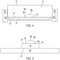
FIG. 4 is a front view of the garden tool ofFIG. 1 -
FIG. 5 is a front view of a charging station for use with the garden tool ofFIGS. 1 and4 . -
FIG. 6 is a front view of a garden tool approaching a charging station. -
FIG. 7 is a front view of the garden tool positioned on the charging station ofFIG. 6 . - Before any embodiments of the invention are explained in detail, it is to be understood that the invention is not limited in its application to the details of construction and the arrangement of components set forth in the following description or illustrated in the following drawings. The invention is capable of other embodiments and of being practiced or of being carried out in various ways. Also, it is to be understood that the phraseology and terminology used herein is for the purpose of description and should not be regarded as limiting.
-
Figures 1-3 illustrate arobotic garden tool 10. More specifically, thegarden tool 10 includes a robotic lawn mower for use to cut vegetation such as grass in an enclosedcutting area 14. Thecutting area 14 generally includes, but is not limited to, a continuous area of grass or other vegetation that is enclosed by one ormore barriers 16. In the illustrated embodiment, thebarriers 16 include a series of electrified wires enclosing thecutting area 14 while in alternative embodiments different form of barrier may be used such as, but not limited to, walls, pavers, GPS data points, and the like. As shown inFIG. 1 ,such barriers 16 may be used to enclose theoverall cutting area 14 and/or to segregate one or more interior regions from thecutting area 14. While the illustratedtool 10 is a robotic mower, it is understood that in alternative embodiments other forms of robotic tool may be used including, but not limited to, a robotic trimmer, a robotic sprinkler, a robotic fertilizer spreader, and the like. - As shown in
FIGS. 2 and3 , thetool 10 is an electrically powered, self-propelled device that includes abody 18, a plurality ofwheels 22 rotatably mounted to thebody 18, aworking tool 26 mounted to thebody 18, aguard 28 extending around theworking tool 26, acontroller 30, abattery 32, and acharging port 80. Thebody 18, in turn, includes a front orfirst end 34, rear orsecond end 38 opposite thefirst end 34, a right orfirst side 42, a left orsecond side 44 opposite thefirst side 42, an upper ortop surface 46 and a lower orbottom surface 48 opposite theupper surface 46. Thebody 18 also defines alongitudinal axis 50 extending along the length of thebody 18 and centered between thefirst side 42 and the second side 44 (e.g., passing through both the first andsecond ends 34, 38). Thebody 18 also defines alateral axis 54 extending along the width of thebody 18 and centered between the first andsecond ends 34, 38 (e.g., passing through both the first andsecond sides 42, 44). Thebody 18 also defines acentral axis 58 generally positioned at the intersection of the longitudinal andlateral axes - As shown in
FIG. 3 , thetool 10 includes fourwheels body 18 and configured to support thetool 10 for self-driven movement along a support surface 60 (e.g., the surface of the cutting area 14). In the illustrated embodiment, thewheels undriven wheels wheels wheels 22 may be driven and all or any sub-set of thewheels 22 may be steerable. Furthermore, while the illustrated steerable wheels are passive in nature (e.g., a caster-style wheel), it is understood that in alternative embodiments thesteerable wheels controller 30. In still other embodiments, thetool 10 may include more orfewer wheels 22 positioned in different arrangements about thetool 10. In still other embodiments, thewheels 22 may be replaced by other forms of propulsion such as, but not limited to, tracks, omni-wheels, walking legs, and the like. - As shown in
FIGS. 2 and3 , the workingtool 26 includes a rotating blade mounted for relative rotation about ablade axis 72. More specifically, theblade 26 is mounted to adedicated blade motor 76 which rotates theblade 26 during use. In the illustrated embodiment, theblade axis 72 is oriented vertically (e.g., parallel to the central axis 58) and positioned proximate the center of thebody 18. In some embodiments, theblade axis 72 may be coincident with thecentral axis 58. While the illustrated workingtool 26 is a rotating blade, it is understood that in alternative embodiments thetool 10 may include, but is not limited to, reciprocating blades, a distributor or dispenser of some kind, and the like. Thetool 10 is configured to travel in a direction V during operation. - As shown in
Figs. 2-4 , thetool 10 also includes a chargingport 80. The chargingport 80 is in operable communication with at least thebattery 32 of thetool 10 and configured to create a temporary electrical connection with a charging station 84 (described below) to convey the electrical energy output by the chargingstation 84 to thebattery 32 for re-charging operations. More specifically, the chargingport 80 includes a concave recess formed into and open to thebottom surface 48 of thebody 18 of thetool 10. As shown inFIGS. 3 and4 , the chargingport 80 includes a central orfirst portion 88a, an outer orsecond portion 88c, and anintermediate portion 88b positioned between and electrically isolating thecentral portion 88a from theouter potion 88c. In the illustrated embodiment, all threeportions central portion 88a, an annularintermediate portion 88b, and an annularouter portion 88c. While the illustrated chargingport 80 is circular in overall shape, it is understood that in other embodiments different shapes of concentric portions be used including, but not limited to, elliptical, polygonal, and the like. - The central and
outer portions port 80 are formed from conductive material (e.g., metal); forming a positive and ground electrode, respectively. In contrast, theintermediate portion 88b is formed from an insulating material to electrically isolate thecentral portion 88a from theouter portion 88c. In other embodiments, thecentral portion 88a may form the ground electrode while theouter portion 88c forms the positive electrode. Furthermore, while the illustrated chargingport 80 includes three portions forming a single set of electrodes (positive and ground and insulating buffer), it is understood that in alternative embodiments more concentric portions may be included to allow for additional circuits to be formed between theport 80 and the chargingstation 84. Such additional circuits may be used for, but are not limited to, data communication, docking verification, and the like. - In the illustrated embodiment, the charging
port 80 is positioned between thefirst end 34 and theguard 28 of the workingtool 26, being centered side-to-side along thelateral axis 54. However, in alternative embodiments the chargingport 80 may be positioned in alternative positions on thebottom surface 48 of thetool 10 to best accommodate the docking process between thetool 10 and the chargingstation 84. For example, in some embodiments the chargingport 80 may be positioned between thesecond end 38 and theguard 28. In still other embodiments, the charging port 80' may be positioned adjacent and open to one of theends body 18 of the tool. In still other embodiments, more than one chargingport 80 may be present on asingle body 18 to accommodate docking approaches from multiple directions and/or conditions. - With reference to
Figs. 2-5 , the chargingstation 84 includes a chargingterminal 92 and a core orbase 90 to support, position, and orient the chargingterminal 92 relative to thesupport surface 60. During use, the chargingstation 84 is electrically connected to a power source, such as a battery or an electrical outlet, whereby the chargingstation 84 is configured to provide an electrical mounting point to which the chargingport 80 of thetool 10 can dock to allow for electrical communication therebetween. - The
base 90 of the chargingstation 84 has anupper surface 94 and alower surface 96. Together, theupper surface 94 and thelower surface 96 produce a vertical base height configured to position the terminal 92 at a height substantially corresponding to the height of theunderside 48 of thetool 10. Thelower surface 96 can be supported on thesupport surface 60. The base 90 can be any suitable shape to accommodate the approach and docking between thetool 10 and the chargingstation 84. In the illustrated embodiment, thebase 90 is sized to fit between thefront wheels tool 10. In other embodiments, thebase 90 may include tapered sidewalls (e.g., narrowing in width as it extends radially outwardly) to help guide thetool 10 into alignment with the chargingterminal 92. In still other embodiments, thebase 90 may have beveled sidewalls (e.g., angled vertically downwardly) to allow thewheels 22 of thetool 10 to ride up onto and across thebase 90. In still other embodiments thebase 90 may include one or more stakes extending therefrom (not shown) to allow the base 90 to be secured to asoft support surface 60 such as soil and the like. In still other embodiments, thebase 90 may be attached to support surface or mat 100 (seeFIG. 5 ) to provide additional support, for example on hard support surfaces 60 such a concrete and the like. - In embodiments, where a
mat 100 is present (seeFIG. 5 ), themat 100 may be wider than thetool 10, such that thetool 10 can be fully supported on themat 100 during the docking process. In some embodiments, themat 100 is positioned directly on thesupport surface 60. In still other embodiments, different forms of support may be interchangeable to the base 90 so the user can accommodate the desired installation location. While the illustratedbase 90 andmat 100 are described as separate elements, it is understood that in still other embodiments thebase 90 andmat 100 may be formed integrally together as a single unit. - The charging
terminal 92 of the chargingstation 94 is sized and shaped to correspond with the size and shape of the chargingport 80 of thetool 10 to form a temporary electrical connection therebetween. In the illustrated embodiment, the chargingterminal 92 is a convex, generally dome-shaped protrusion, extending from theupper surface 94 of thebase 90. As shown inFIG. 5 , the terminal 92 includes a first orcentral portion 98a, a second orouter portion 98c, and anintermediate portion 98b extending between and electrically isolating thecentral portion 98a from theouter portion 98c. - In the illustrated embodiment, all three
portion portions port 80. More specifically, the illustratedouter portion 98c encircles theintermediate portion 98b, and the illustratedintermediate portion 98b encircles thecentral portion 98a. Similar to the chargingport 80, theintermediate portion 98b is formed from an insulating material while the central andouter portions outer portion 98c is a positive electrode, and thecentral portion 98a is a ground electrode to mirror the layout of the chargingport 80. In other embodiments, thecentral portion 98a is the positive electrode and theouter portion 98c is the ground electrode. Other shapes, sizes and configurations of charging terminals can be utilized in other embodiments. For example, in some embodiments the threeportions - At least a portion of the charging
terminal 92 is made from a resilient, flexible material to permit deformation of the chargingterminal 92 to accommodate thebody 18 of thetool 10. More specifically, the dome shape of the chargingterminal 92 causes the chargingterminal 92 to act as a spring, whereby the terminal 92 will deform when subject to an external force (e.g., contacting thebody 18 of the tool 10) and resiliently return to the original domed shape upon removal of the external force. This permits the terminal 92 to deform out of the way of thebody 18 and resiliently expand up and into the chargingport 80 once aligned therewith. In other embodiments, thefirst end 34 of thetool 10 includes a resilient, deformable material that deforms in response to thefirst end 34 of thetool 10 moving across the chargingterminal 92. - The charging
terminal 92 is sized to be at least partially received within the chargingport 80 such that thecentral portions outer portions - During use, the charging
station 84 is configured so that thetool 10 can approach the chargingstation 84 from any direction and the chargingport 80 of thetool 10 and the chargingterminal 92 of the chargingstation 84 can form an electrical connection. - To dock the
tool 10 to the chargingterminal 92, thetool 10 first approaches the chargingstation 84 while traveling in a direction V. As stated above, thetool 10 may approach the charging station radially from any direction across a 360-degree arc. - After the
tool 10 reaches the terminal 92, thefirst end 34 contacts the terminal 92 and begins to deform the terminal 92. More specifically, thefirst end 34 vertically compresses the terminal 92 such that the terminal 92 can pass below thebody 18 while being in contact with thebottom surface 48 thereof. The terminal 92 then remains compressed below thebody 18 until the terminal 92 becomes aligned with the chargingport 80. Once aligned, the terminal 92 will resiliently expand back to its original configuration - expanding upwardly into the recess of the chargingport 80. By doing so, the central andouter portions outer portions port 80 respectively. With the electrical connection made, the chargingstation 84 may then provide electrical power to thebattery 32 of thetool 10 for the charging process. - After the charging process is complete, the
tool 10 may disengage from the terminal 92. To do so, thetool 10 may travel in a second direction, opposite the direction V, whereby the terminal 92 is again compressed by thebody 18 of thetool 10 so that it can pass underneath thebottom surface 48 thereof. After thetool 10 is no longer overlapping the terminal 92, the terminal 92 can resiliently expand back to its original dome-shaped configuration. - Although not shown, in alternative embodiments, the resiliency of the terminal 92 may permit the
tool 10 to continue to travel in direction V after the charging process is complete. By doing so, thetool 10 does not need to turn or maneuver after the charging process. - In some alternative embodiments, one or more ramps or moving members can raise the
front end 34 of thetool 10 over the chargingterminal 92 and then lower thetool 10 when the chargingport 80 is generally aligned with the chargingterminal 92. Such ramps can be used together with the resilient nature of the terminal 92 (e.g., so that less deformation is required to allow the terminal 92 to pass under the body 18), or in place of the resiliency (e.g., the vertical displacement produced by the ramps produce the necessary clearance for the terminal 92 to pass under the body 18). - In still other alternative embodiments, a switch and/or sensor may be coupled to the
mat 100 to sense the presence of thetool 10. While thetool 10 is not positioned on themat 100, the chargingstation 84 is configured to supply a first charge to the chargingterminal 92. While thetool 10 is positioned on themat 100, the chargingstation 84 is configured to provide a second charge to the chargingterminal 92. The first charge is smaller, and in some cases, significantly smaller, than the second charge. In some embodiments, the first charge is between 0 and 30 volts, and the second charge is greater than 30 volts. In some embodiments, the first charge is between 0 and 20 volts, and the second charge is greater than 35 volts. - In still other embodiments, the charging port 80' is in the shape of a half dome adjacent and open to one of the
ends FIG. 2A ). In such embodiments, thecentral portion 88a is a semi-circle that abuts thefirst end 34 of thetool 10, and theintermediate portion 88b andouter portion 88c extend in a semi-circular ring with each end abutting thefirst end 34 of thetool 10. The chargingterminal 92 could still remain as a full dome to permit thetool 10 to approach the chargingstation 84 from any number of directions. In some embodiments, thetool 10 is configured to depart from the chargingstation 84 in a different direction than it approached the chargingstation 84. - In still other embodiments, debris, such as grass clippings, may be removed from the charging
port 80 while thetool 10 approaches the chargingstation 84 to allow for a better electrical connection to be formed therebetween. For example, a blower (not shown) can be activated by the presence of thetool 10 on or near the chargingstation 84. The blower can be angled upward to blow air into and across the chargingport 80 prior to the chargingterminal 92 extending into the chargingport 80. In still other embodiments, a brush (not shown) may be coupled to the chargingstation 84, (i.e., extending upwardly from an upper surface of the mat 100) so that when thetool 10 approaches the chargingstation 84, the brush extends upwardly into at least a portion of the chargingport 80. By doing so, the process of traveling over the brush causes the brush to wipe away any debris located within the chargingport 80 prior to the chargingterminal 92 extending into the chargingport 80. -
Figs. 6 and7 illustrate another embodiment of atool 210 and a chargingstation 284. Thetool 210 and chargingstation 284 are substantially similar to thetool 10 and chargingstation 84 described above. As such, only the differences will be discussed in detail herein. The chargingport 280 of thetool 210 is in operable communication with at least thebattery 232 of thetool 210 and configured to create a temporary electrical connection with a charging station 284 (described below) to convey the electrical energy output by the chargingstation 284 to thebattery 232 for re-charging operations. More specifically, the illustrated chargingport 280 includes afirst electrode 286 and asecond electrode 288. Thefirst electrode 286 includesfirst contact 286a and a firstflexible member 286b, and thesecond electrode 288 includes asecond contact 288a and a secondflexible member 288b. In some embodiments, thefirst electrode 286 is a positive electrode and thesecond electrode 288 is a ground electrode. In other embodiments, thefirst electrode 286 is the ground electrode andsecond electrode 288 is the positive electrode. - The
flexible members electrodes respective contacts body 218. Theflexible members respective contact lower surface 248 of thebody 218 until being biased away therefrom by an external force (e.g., contact withelectrode docking station 284, described below). At least a portion of thefirst contact 286a, and a least a portion of thesecond contact 288a is formed from a conductive material. - The illustrated charging
port 280 is positioned between a front end of thebody 218 and theguard 228. In some embodiments, the chargingport 280 may be positioned between a rear end of thebody 218 and theguard 228. Other shapes, sizes and configurations of charging ports can be utilized in other embodiments. - The charging
station 284 includes abase 290 and a chargingterminal 292. The chargingstation 284 is configured to provide an electrical mounting point to which the chargingport 280 of thetool 210 can dock to allow for temporary electrical communication therebetween. Thebase 290 of the chargingstation 284 includes anupper surface 294 and alower surface 296. When installed, thelower surface 296 can be supported on asupport surface 60 while theupper surface 294 is configured to support at least two of thewheels 222 of thetool 10 thereon. In the illustrated embodiment, thebase 290 may include a beveled edge or ramp to allow thewheels 222 of thetool 210 to drive up onto and traverse across theupper surface 294 of thebase 290. The illustratedbase 290 is larger than thetool 210, such that thetool 210 can be fully supported on thebase 290. In still other embodiments, different forms of support may be interchangeable to the base 290 so the user can accommodate the desired installation location. - The charging
station 284 is electrically connected to a power source, such as a battery or an electrical outlet. The chargingterminal 292 includes afirst electrode 298 and asecond electrode 302. Thefirst electrode 298 is an elongate member movably coupled to thebase 290 for pivoting about the base 290 between a first or stowed position (seeFIG. 6 ) and a second or deployed position (seeFIG. 7 ). In the first position, the first or contact end of thefirst electrode 298 is positioned near or below theupper surface 294 of the base 290 (e.g., thefirst electrode 298 does not engage or make an electrical connection with atool 210 positioned on the charging station 284) while in the second position, the contact end of thefirst electrode 298 extends vertically above theupper surface 294 of the base 290 (e.g., thefirst electrode 298 does engage and make an electrical connection with atool 210 positioned on the charging station 284). In the illustrated embodiment, the contact end of thefirst electrode 298 is formed from a conductive material. - The
second electrode 302 is an elongate member coupled to thebase 290 for pivoting about the base 290 between a first or stowed position (seeFIG. 6 ) and a second or deployed position (seeFIG. 7 ). In the first position, the first or contact end of thesecond electrode 302 is positioned near or below theupper surface 294 of the base 290 (e.g., thesecond electrode 302 does not engage or make an electrical connection with atool 210 positioned on the charging station 284), while in the second position, the contact end of thesecond electrode 302 extends vertically above the upper surface of the base 290 (e.g., thesecond electrode 302 does engage and form an electrical connection with atool 210 positioned on the charging station 284). In the illustrated embodiment, the contact end of the second electrode 201 is formed from a conductive material. - The base 290 also includes a first
moveable plate member 306 supported on a first biasing member and a secondmoveable plate member 308 supported on a second biasing member. The first and secondmoveable plate member wheels 222 thereon. More specifically, bothmovable plate members plate members upper surface 294 of the base 290 (seeFIG. 6 ), and a displaced position, in which theplate members FIG. 7 ). The illustrated first biasing member is a pair ofcoil springs 310a, 31 0b, and the illustrated second biasing member is a pair ofcoil springs - As shown in
FIGS. 6 and7 , the firstmoveable plate member 306 is coupled to a second end of thefirst electrode 298 so that vertical movement of the firstmovable plate member 306 between the rest and displaced positions causes thefirst electrode 284 to pivot between the stowed and deployed positions. More specifically, the firstmovable plate member 306 is configured so that thefirst electrode 284 is in the stowed position when theplate 306 is in the rest position (seeFIG. 6 ), and wherein moving theplate member 306 toward the displaced position causes thefirst electrode 284 to pivot from the stowed position toward the deployed position (seeFIG. 7 ). - The second
moveable plate member 308 is coupled to a second end of thesecond electrode 302 so that vertical movement of the secondmovable plate member 308 between the rest and displaced positions causes thesecond electrode 302 to pivot between the stowed and deployed positions. More specifically, the secondmovable plate member 308 is configured so that thesecond electrode 302 is in the stowed position when theplate 308 is in the rest position (seeFIG. 6 ), and wherein moving theplate member 308 from the rest position toward the displaced position causes thesecond electrode 302 to pivot from the stowed position toward the deployed position (seeFIG. 7 ). - During use, the
tool 210 may drive up onto theupper surface 294 of the base 290 until each of the front twowheels 222 are positioned on a corresponding one of theplate members tool 210 in position, the weight of thetool 210 presses theplate members respective coil springs plate electrodes first electrode 298 andsecond electrode 302 engage and form an electrical connection with thesecond contact 288 and thefirst contact 286, respectively. Upon removal of thetool 210 from theplate members coil springs respective plate members Fig. 6 ). - In some embodiments, the
first electrode 298 is a positive electrode and thesecond electrode 302 is a ground electrode. In other embodiments, thefirst electrode 298 is the ground electrode andsecond electrode 302 is the positive electrode. Other shapes, sizes and configurations of charging terminals can be utilized in other embodiments. - In some embodiments, a switch and/or sensor is coupled to the base 290 to sense the presence of the
tool 210. While thetool 210 is not positioned on the base 290 (i.e.,Fig. 6 ), the chargingstation 284 is configured to supply a first charge to the chargingterminal 292. While thetool 210 is positioned on the base 290 (i.e.,FIG. 7 ), the chargingstation 284 is configured to provide a second charge to the chargingterminal 292. The first charge is smaller, and in some cases, significantly smaller, than the second charge. In some embodiments, the first charge is between 0 and 30 volts, and the second charge is greater than 30 volts. In some embodiments, the first charge is between 0 and 20 volts, and the second charge is greater than 35 volts. - In some embodiments, debris, such as grass clippings, is removed from the charging
port 280 while thetool 210 approaches the chargingstation 284. For example, a blower (not shown) can be activated by the presence of thetool 210 on or near the chargingstation 284. The blower can be angled upward to blow air into and across the first andsecond contacts port 280 prior to engaging therespective electrode terminal 292. In some instances, a brush (not shown) is coupled to the chargingstation 284, (i.e., extending upwardly from an upper surface of the base 290). When thetool 210 approaches the chargingstation 284, the brush extends upwardly into at least a portion of the chargingport 280 to clean off the first andsecond contacts second electrodes second contacts 286a, 296b. - Both of the
robotic garden tool robotic garden tool
Claims (20)
- A charging station for use with a robotic garden tool, the charging station comprising:a base having an upper surface and a lower surface, the lower surface of the base being configured to be supported on a support surface;a charging terminal coupled to the upper surface of the base, wherein the charging terminal includes a positive electrode and a ground electrode electrically insulated from the positive electrode, wherein the positive electrode and the ground electrode are configured to selectively extend upward to a location vertically above the upper surface of the base.
- The charging station of claim 1, wherein the charging terminal is convex and includes a flexible material to permitdeformation of the convex charging terminal.
- The charging station of claim 2, wherein the charging terminal includes an outer portion, an intermediate portion and a central portion, the outer portion substantially encircling the intermediate portion, and the intermediate portion substantially encircling the central portion, wherein the outer portion and the central portion are formed from a conductive material and wherein the intermediate portion is formed from an insulating material.
- The charging station of claim 1, wherein the charging terminal includes a plurality of radially nested portions.
- The charging station of claim 1, wherein the charging terminal includes a moveable member configured to move from a first position in which the moveable member is near the upper surface of the base and a second position in which the moveable member extends vertically above the upper surface of the base, wherein at least a portion of the moveable member is formed from a conductive material.
- The charging station of claim 5, wherein the moveable member is configured to pivot between the first position and the second position.
- The charging station of claim 1, wherein the charging terminal includes a first moveable member configured to move from a first position in which the first moveable member is near the upper surface of the base and a second position in which the first moveable member extends vertically above the upper surface of the base, at least a portion of the first moveable member is formed from a conductive material, and a second moveable member configured to move from a first position in which the second moveable member is near the upper surface of the core and a second position in which the second moveable member extends vertically above the upper surface of the base, at least a portion of the second moveable member is formed from a conductive material.
- A robotic garden tool comprising:a body having a front end, a rear end opposite the front end, an upper surface and a lower surface opposite the upper surface;one or more driven wheels mounted to the body;a working tool mounted to the body;a battery; anda charging port open to the lower surface of the body, the charging port including a positive electrode, and a ground electrode that is electronically isolated from the positive electrode.
- The robotic garden tool of claim 8, wherein the charging port is positioned between the front end and the working tool.
- The robotic garden tool of claim 8 wherein the charging port is concave such that the positive and ground electrodes extend into the body.
- The robotic garden tool of claim 8, wherein the charging port includes an outer portion, an intermediate portion and a central portion, the outer portion substantially encircling the intermediate portion, and the intermediate portion substantially encircling the central portion, wherein the outer portion and the central portion are formed from a conductive material and wherein the intermediate portion is formed from an insulating material.
- The robotic garden tool of claim 8, wherein the charging port includes a plurality of radially nested portions.
- The robotic garden tool of claim 8, wherein the charging port includes a contact coupled to a flexible member, the flexible member permitting limited vertical movement of the contact with respect to the body, the flexible member retaining the contact near the lower surface of the body, wherein at least a portion of the contact is formed from a conductive material.
- The robotic garden tool of claim 13, wherein the contact is a first contact the flexible member is a first flexible member, the charging port further comprising a second contact coupled to a second flexible member, the second flexible member permitting limited vertical movement of the second contact with respect to the body, the second flexible member retaining the second contact near the lower surface of the body, wherein at least a portion of the second contact is formed from a conductive material.
- A charging station for use with a robotic garden tool, the charging station comprising:a base; anda charging terminal coupled to the base, wherein the charging terminal includes a positive electrode and a ground electrode electrically insulated from the positive electrode, wherein the charging terminal is convex.
- The charging station of claim 15, wherein the positive electrode and the ground electrode are electrically isolated from one another by an intermediate portion.
- The charging station of claim 16, wherein the positive electrode and the ground electrode are formed from conductive material and wherein the intermediate portion is formed from an insulating material.
- The charging station of claim 16, wherein the charging terminal includes an outer portion, the intermediate portion and a central portion, the outer portion substantially encircling the intermediate portion, and the intermediate portion substantially encircling the central portion.
- The charging station of claim 16, wherein the outer portion forms one of the ground electrode and the positive electrode and wherein the central portion forms the other of the ground electrode and the positive electrode.
- The charging station of claim 15, wherein charging terminal is resiliently deformable.
Applications Claiming Priority (1)
| Application Number | Priority Date | Filing Date | Title |
|---|---|---|---|
| US202263333384P | 2022-04-21 | 2022-04-21 |
Publications (2)
| Publication Number | Publication Date |
|---|---|
| EP4266538A2 true EP4266538A2 (en) | 2023-10-25 |
| EP4266538A3 EP4266538A3 (en) | 2024-02-28 |
Family
ID=86095846
Family Applications (1)
| Application Number | Title | Priority Date | Filing Date |
|---|---|---|---|
| EP23168751.8A Pending EP4266538A3 (en) | 2022-04-21 | 2023-04-19 | Robotic tool and charging station |
Country Status (4)
| Country | Link |
|---|---|
| US (1) | US20230339347A1 (en) |
| EP (1) | EP4266538A3 (en) |
| CN (1) | CN116923136A (en) |
| AU (1) | AU2023202378A1 (en) |
Families Citing this family (2)
| Publication number | Priority date | Publication date | Assignee | Title |
|---|---|---|---|---|
| US20230369872A1 (en) * | 2022-05-12 | 2023-11-16 | Techtronic Cordless Gp | Robotic tool and charging station |
| US12451708B2 (en) * | 2022-11-28 | 2025-10-21 | Industrial Technology Research Institute | Docking structure and a docking device comprising the same |
Family Cites Families (2)
| Publication number | Priority date | Publication date | Assignee | Title |
|---|---|---|---|---|
| CN105553033B (en) * | 2016-02-02 | 2018-02-23 | 深圳市神州云海智能科技有限公司 | Charging pile and mobile robot |
| CN109390729B (en) * | 2018-12-18 | 2024-09-13 | 上海木木聚枞机器人科技有限公司 | Robot charging system and method |
-
2023
- 2023-04-18 AU AU2023202378A patent/AU2023202378A1/en active Pending
- 2023-04-19 EP EP23168751.8A patent/EP4266538A3/en active Pending
- 2023-04-20 US US18/304,141 patent/US20230339347A1/en active Pending
- 2023-04-21 CN CN202310438233.9A patent/CN116923136A/en active Pending
Also Published As
| Publication number | Publication date |
|---|---|
| AU2023202378A1 (en) | 2023-11-09 |
| CN116923136A (en) | 2023-10-24 |
| US20230339347A1 (en) | 2023-10-26 |
| EP4266538A3 (en) | 2024-02-28 |
Similar Documents
| Publication | Publication Date | Title |
|---|---|---|
| US20230339347A1 (en) | Robotic tool and charging station | |
| US12054062B2 (en) | Robotic work tool system and a charging connector arrangement for a robotic work tool system | |
| US10873194B2 (en) | Docking station for autonomous mobile robots | |
| US11589504B2 (en) | Robotic lawnmower with passive cleaning assembly | |
| US12082524B2 (en) | Autonomous lawn mower with edger and control method thereof | |
| EP3571917B1 (en) | Lawn mower | |
| AU2017282030B2 (en) | High-efficiency cutting system | |
| US20230369872A1 (en) | Robotic tool and charging station | |
| US9557739B2 (en) | Sensor cleaning system for an autonomous robot device, base station and corresponding method | |
| WO2019062212A1 (en) | Automatic lawn trimmer and automatic lawn trimming method | |
| AU2023200508A1 (en) | Robotic garden tool with manual blade height adjustment and movable blade guard | |
| US20240415051A1 (en) | Autonomous Lawn Mower with Edger and Control Method Thereof | |
| EP2241172A1 (en) | Lawn-mower | |
| EP4265097A1 (en) | Garden tool power source compartment having drainage | |
| EP4245115A1 (en) | Robotic garden tool with implement height adjustment | |
| AU2023202377A1 (en) | Robotic tool and charging station | |
| CN116508480A (en) | Robotic garden tool with manual blade height adjustment and movable blade guard | |
| RU2773946C2 (en) | Electric drive disc mower | |
| CN116960667A (en) | Robot Tools and Charging Stations | |
| JP2004129506A (en) | Lawn, mower |
Legal Events
| Date | Code | Title | Description |
|---|---|---|---|
| STAA | Information on the status of an ep patent application or granted ep patent |
Free format text: STATUS: THE APPLICATION HAS BEEN PUBLISHED |
|
| PUAI | Public reference made under article 153(3) epc to a published international application that has entered the european phase |
Free format text: ORIGINAL CODE: 0009012 |
|
| AK | Designated contracting states |
Kind code of ref document: A2 Designated state(s): AL AT BE BG CH CY CZ DE DK EE ES FI FR GB GR HR HU IE IS IT LI LT LU LV MC ME MK MT NL NO PL PT RO RS SE SI SK SM TR |
|
| PUAL | Search report despatched |
Free format text: ORIGINAL CODE: 0009013 |
|
| AK | Designated contracting states |
Kind code of ref document: A3 Designated state(s): AL AT BE BG CH CY CZ DE DK EE ES FI FR GB GR HR HU IE IS IT LI LT LU LV MC ME MK MT NL NO PL PT RO RS SE SI SK SM TR |
|
| RIC1 | Information provided on ipc code assigned before grant |
Ipc: A01D 34/00 20060101ALI20240124BHEP Ipc: H02J 7/00 20060101AFI20240124BHEP |
|
| STAA | Information on the status of an ep patent application or granted ep patent |
Free format text: STATUS: REQUEST FOR EXAMINATION WAS MADE |
|
| 17P | Request for examination filed |
Effective date: 20240822 |
|
| RBV | Designated contracting states (corrected) |
Designated state(s): AL AT BE BG CH CY CZ DE DK EE ES FI FR GB GR HR HU IE IS IT LI LT LU LV MC ME MK MT NL NO PL PT RO RS SE SI SK SM TR |