EP4266362A1 - Compressing structure, power module and a method for compressing a component inside a chamber - Google Patents
Compressing structure, power module and a method for compressing a component inside a chamber Download PDFInfo
- Publication number
- EP4266362A1 EP4266362A1 EP23159818.6A EP23159818A EP4266362A1 EP 4266362 A1 EP4266362 A1 EP 4266362A1 EP 23159818 A EP23159818 A EP 23159818A EP 4266362 A1 EP4266362 A1 EP 4266362A1
- Authority
- EP
- European Patent Office
- Prior art keywords
- compressing
- plate
- housing
- shaped structure
- press
- Prior art date
- Legal status (The legal status is an assumption and is not a legal conclusion. Google has not performed a legal analysis and makes no representation as to the accuracy of the status listed.)
- Granted
Links
Images




Classifications
-
- H—ELECTRICITY
- H05—ELECTRIC TECHNIQUES NOT OTHERWISE PROVIDED FOR
- H05K—PRINTED CIRCUITS; CASINGS OR CONSTRUCTIONAL DETAILS OF ELECTRIC APPARATUS; MANUFACTURE OF ASSEMBLAGES OF ELECTRICAL COMPONENTS
- H05K5/00—Casings, cabinets or drawers for electric apparatus
- H05K5/02—Details
- H05K5/0217—Mechanical details of casings
-
- H—ELECTRICITY
- H10—SEMICONDUCTOR DEVICES; ELECTRIC SOLID-STATE DEVICES NOT OTHERWISE PROVIDED FOR
- H10W—GENERIC PACKAGES, INTERCONNECTIONS, CONNECTORS OR OTHER CONSTRUCTIONAL DETAILS OF DEVICES COVERED BY CLASS H10
- H10W40/00—Arrangements for thermal protection or thermal control
- H10W40/60—Securing means for detachable heating or cooling arrangements, e.g. clamps
- H10W40/611—Bolts or screws
-
- B—PERFORMING OPERATIONS; TRANSPORTING
- B30—PRESSES
- B30B—PRESSES IN GENERAL
- B30B15/00—Details of, or accessories for, presses; Auxiliary measures in connection with pressing
- B30B15/06—Platens or press rams
- B30B15/062—Press plates
-
- H—ELECTRICITY
- H01—ELECTRIC ELEMENTS
- H01F—MAGNETS; INDUCTANCES; TRANSFORMERS; SELECTION OF MATERIALS FOR THEIR MAGNETIC PROPERTIES
- H01F27/00—Details of transformers or inductances, in general
- H01F27/02—Casings
- H01F27/025—Constructional details relating to cooling
-
- H—ELECTRICITY
- H01—ELECTRIC ELEMENTS
- H01F—MAGNETS; INDUCTANCES; TRANSFORMERS; SELECTION OF MATERIALS FOR THEIR MAGNETIC PROPERTIES
- H01F27/00—Details of transformers or inductances, in general
- H01F27/06—Mounting, supporting or suspending transformers, reactors or choke coils not being of the signal type
-
- H—ELECTRICITY
- H01—ELECTRIC ELEMENTS
- H01F—MAGNETS; INDUCTANCES; TRANSFORMERS; SELECTION OF MATERIALS FOR THEIR MAGNETIC PROPERTIES
- H01F27/00—Details of transformers or inductances, in general
- H01F27/08—Cooling; Ventilating
- H01F27/22—Cooling by heat conduction through solid or powdered fillings
-
- B—PERFORMING OPERATIONS; TRANSPORTING
- B30—PRESSES
- B30B—PRESSES IN GENERAL
- B30B1/00—Presses, using a press ram, characterised by the features of the drive therefor, pressure being transmitted directly, or through simple thrust or tension members only, to the press ram or platen
- B30B1/40—Presses, using a press ram, characterised by the features of the drive therefor, pressure being transmitted directly, or through simple thrust or tension members only, to the press ram or platen by wedge means
-
- F—MECHANICAL ENGINEERING; LIGHTING; HEATING; WEAPONS; BLASTING
- F16—ENGINEERING ELEMENTS AND UNITS; GENERAL MEASURES FOR PRODUCING AND MAINTAINING EFFECTIVE FUNCTIONING OF MACHINES OR INSTALLATIONS; THERMAL INSULATION IN GENERAL
- F16B—DEVICES FOR FASTENING OR SECURING CONSTRUCTIONAL ELEMENTS OR MACHINE PARTS TOGETHER, e.g. NAILS, BOLTS, CIRCLIPS, CLAMPS, CLIPS OR WEDGES; JOINTS OR JOINTING
- F16B2/00—Friction-grip releasable fastenings
- F16B2/02—Clamps, i.e. with gripping action effected by positive means other than the inherent resistance to deformation of the material of the fastening
- F16B2/14—Clamps, i.e. with gripping action effected by positive means other than the inherent resistance to deformation of the material of the fastening using wedges
-
- H—ELECTRICITY
- H10—SEMICONDUCTOR DEVICES; ELECTRIC SOLID-STATE DEVICES NOT OTHERWISE PROVIDED FOR
- H10W—GENERIC PACKAGES, INTERCONNECTIONS, CONNECTORS OR OTHER CONSTRUCTIONAL DETAILS OF DEVICES COVERED BY CLASS H10
- H10W40/00—Arrangements for thermal protection or thermal control
- H10W40/60—Securing means for detachable heating or cooling arrangements, e.g. clamps
-
- H—ELECTRICITY
- H10—SEMICONDUCTOR DEVICES; ELECTRIC SOLID-STATE DEVICES NOT OTHERWISE PROVIDED FOR
- H10W—GENERIC PACKAGES, INTERCONNECTIONS, CONNECTORS OR OTHER CONSTRUCTIONAL DETAILS OF DEVICES COVERED BY CLASS H10
- H10W40/00—Arrangements for thermal protection or thermal control
- H10W40/60—Securing means for detachable heating or cooling arrangements, e.g. clamps
- H10W40/641—Snap-on arrangements, e.g. clips
Definitions
- the invention relates to the technical field of power electronics, and specifically to a compressing structure.
- power modules are an important part in effectively reducing the volume of the power distribution system and improving the reliability of system.
- the primary side and the secondary side of the transformer are generally entirely covered with insulating material, the volume of which is large, and the heat dissipation is difficult due to poor thermal conductivity of insulating materials.
- Adopting split type transformer can effectively reduce the volume of the transformer and a fan can blow directly to a magnetic core body and windings of the primary side and secondary side of the transformer so that the heat dissipation capability is improved thereof.
- the primary side and secondary side of the transformer need to be fixed in the insulating housing.
- the operating space inside the chamber of the housing is small and installation and positioning is difficult which makes it difficult to realize the fixation and clamping of the transformer; and a gap exists between a fixed plate and the magnetic core because of manufacturing or assembly errors which affects the excitation inductance value of the transformer.
- the invention provides a compressing structure for compressing a component, which compresses the component to a fixed plate.
- embodiments of the invention provides a compressing structure for compressing a component, wherein the compressing structure is provided for compressing a component to a fixed plate, the compressing structure comprising: a plate-shaped structure, comprising a first surface and a second surface disposed opposite to each other, and a side surface connected between the first surface and the second surface, the component is fixed on the first surface of the plate-shaped structure and the plate-shaped structure is provided with a base on the outside; at least a steering compressing member is provided between the second surface of the plate-shaped structure and the base, and is mounted on the second surface of the plate-shaped structure or the base, the steering compressing member is provided for transforming an external rotational motion around a first rotation axis into a translational motion along a first direction, in which the first direction is perpendicular to the second surface of the plate-shaped structure, and the extension direction of the first rotation axis is perpendicular to the first direction; and at least a positioning device mounted on the side surface of the plate-
- the compressing structure is disposed inside a chamber of a housing for compressing the component inside the chamber, and the housing comprises four side walls which are sequentially connected to form the chamber; the fixed plate is disposed inside the chamber, and dividing the chamber into a first space and a second space; or the fixed plate is one of the side walls.
- each steering compressing member comprising: a compressing mechanism housing comprising a slope and a threaded hole; a transmission slanted block fitting with the slope of the compressing mechanism housing; a fastening bolt passing through the threaded hole of the compressing mechanism housing and abutting on the transmission slanted block; and a press-fit plate mounted on the side of the transmission slanted block away from the compressing mechanism housing; wherein, when the fastening bolt is rotated along the first rotation axis, the fastening bolt moves along the extension direction of the first rotation axis to push the transmission slanted block slides along the slope of the compressing mechanism housing such that the press-fit plate contacts with the side walls of the housing to produce a compressing force.
- the steering compressing member further comprising a motion positioning block, a pin and a first spring, wherein, the transmission slanted block and the motion positioning block are disposed on both sides of the slope of the compressing mechanism housing respectively and connected by the pin; a long empty slot is provided on the slope of the compressing mechanism housing and the pin is disposed through the long empty slot; a long groove corresponding to the long empty slot is provided on the contact slope of the transmission slanted block, where the transmission slanted block and the slope of the compressing mechanism housing fitting with, and a pin hole is provided on one end inside the long groove in which the pin is disposed; the first spring is provided between the pin hole and another end of the long groove for providing a reset force for the sliding of the transmission slanted block.
- the steering compressing member further comprising a press-fit rod and a second spring;
- the transmission slanted block and the press-fit plate are connected by the press-fit rod, which passes through the transmission slanted block and is threaded connected with the press-fit plate;
- the second spring is sleeved on the press-fit rod which is located between the transmission slanted block and the press-fit plate;
- the transmission slanted block is provided for driving the press-fit plate, the press-fit rod and the second spring to slide together along the slope of the compressing mechanism housing; when the fastening bolt continues to be rotated along the first rotation axis, the press-fit plate compresses the second spring and compresses the plate-shaped structure along the first direction until the component is compressed to the fixed plate.
- each positioning device comprising a positioning member and a positioning external member correspondingly sleeved outside of the positioning member, the second rotation axis is the rotation axis of the positioning member , and the second rotation axis is perpendicular to the side surface of the plate-shaped structure; wherein, the positioning member is fixed on the side surface of the plate-shaped structure and the positioning external member is fixed on the base; or the positioning external member is fixed on the side surface of the plate-shaped structure and the positioning member is fixed on the base.
- a first reserved gap, which is along the second direction, and a second reserved gap, which is along the radial direction perpendicular to the second direction, are provided between the positioning external member and the positioning member, such that the plate-shaped structure has a degree of freedom of rotating around the second rotation axis and a degree of freedom of rotating around a third rotation axis which extends along a third direction perpendicular to the first direction and the second direction.
- a radiating fin is disposed on the plate-shaped structure for heat dissipation.
- the plate-shaped structure and the component are fixed by means of bolting or gluing.
- the base is a separate structural member distinguished from the housing, and the base is located between the plate-shaped structure and the side walls of the housing, and it is provided with a through-hole, from which a press-fit plate of the steering compressing member extends against the side walls of the housing, and the base comprising at least a side surface for securing the positioning device.
- the base is formed by the side walls of the housing, and the plate-shaped structure is mounted on the side walls of the housing through the positioning device.
- the number of the steering compressing member is two, and the two steering compressing members are disposed on upper and lower ends of the plate-shaped structure respectively; or the number of the steering compressing member is one, and the steering compressing member is disposed in the middle of the plate-shaped structure.
- the component is a transformer or IGBT.
- Embodiments of the invention also provides a power module comprising a housing, a high-voltage circuit, a low-voltage circuit and a transformer, wherein, the housing comprising four side walls sequentially connected to form a chamber, and a fixed plate disposed inside the chamber dividing the chamber into a first space and a second space; the high-voltage circuit is electrically connected to a primary side of the transformer and the low-voltage circuit is electrically connected to a secondary side of the transformer, and the high-voltage circuit and the primary side of the transformer are in the first space and the low-voltage circuit and the secondary side of the transformer are in the second space; fitting the primary side and secondary side of the transformer closely to the fixed plate respectively by adopting the compressing structure as mentioned above.
- Embodiments of the invention also provides a method for compressing a component inside a chamber comprising steps of: providing a compressing structure which adopting the compressing structure as mentioned above; disposing the compressing structure inside the chamber of the housing ,and there are gaps between the component and the fixed plate, and between the press-fit plate of the steering compressing member and side walls of the housing; inserting a screwdriver through a port of the housing and rotating a fastening bolt, such that the fastening bolt moves along its axial direction to push the transmission slanted block to slide along the slope, then the press-fit plate on the transmission slanted block slides with the transmission slanted block until it fits with the side walls of the housing; continuing rotating the screwdriver so that the press-fit plate presses the side walls of the housing, thereby a reaction force is generated to push the component to gradually approach the fixed plate until they are in contact.
- orientations or positional relations or parameters indicated by terms “transverse”, “longitudinal”, “up”, “down”, “front”, “back”, “left”, “right”, “vertical”, “horizontal”, “top”, “bottom”, “in”, “out” and “about”, or “approximately”, “substantially”, “around” are orientations or positional relations illustrated in the drawings, and only to describe the invention and simplify the description, not indicating or suggesting that the referred device or element must have specific orientations, specific sizes or is constructed or operated in specific orientations, so they also cannot be understood as limitation to the invention.
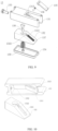
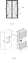
- FIGS. 1-2 are schematic diagrams of the structure of a power module.
- the power module includes a housing 1', a high-voltage circuit c, a low-voltage circuit d and a transformer, the transformer includes a primary side a and a secondary side b, which includes a magnetic core and windings respectively.
- a fixed plate 1' 1' is disposed inside a chamber of the housing 1', and dividing the chamber of the housing 1' into a first space 1'2' and a second space 1'3'.
- the primary side a of the transformer and the high-voltage circuit c are located in the first space 1'2', and the secondary side b of the transformer and the low-voltage circuit d are located in the second space 1'3'; the primary side a and the secondary side b of the transformer needs to be fixed on both sides of the fixed plate 1' 1' respectively.
- the mounting and positioning of the transformer is difficult which makes it difficult to realize the fixation and clamping of the magnetic core of the transformer; also because there are manufacturing or assembly errors, such as the fixed plate 1'1' is prone to deformation and the transformer is not mounted in place, resulting in a distance between the primary side a and the secondary side b of the transformer being greater than a thickness D of the fixed plate 21, which affects excitation inductance value of the transformer. Therefore, a compressing structure is needed to fit the primary side a and the secondary side b of the transformer closely to the fixed plate 21 respectively. The compressing structure is described in detail below.
- FIG. 3 is a schematic diagram of the structure of the compressing structure shown in a first embodiment of the invention.
- FIG. 4 is a partial schematic diagram of the structure of the compressing structure shown in the first embodiment of the invention, wherein part of a base is omitted.
- FIG. 5 is an exploded view of the compressing structure shown in the first embodiment of the invention.
- FIG. 6 is a schematic diagram of the structure of the compressing structure shown in the first embodiment of the invention in another view.
- the compressing structure 1 is provided for compressing a component 3 to a fixed plate 21 inside a chamber of a housing 2.
- the compressing structure 1 includes a plate-shaped structure 11, at least a steering compressing member 13 and at least a positioning device 14.
- the plate-shaped structure 11 comprises a first side surface 111 and a second side surface 112 disposed opposite to each other and a side surface 113 connected between the first side surface 111 and the second side surface 112.
- the component 3 is fixed on the first side surface 111 of the plate-shaped structure 11 and the plate-shaped structure 11 is provided with a base on the outside.
- the steering compressing member 13 is provided between the second side surface 112 of the plate-shaped structure 11 and the base 12, and is mounted on the second side surface 112 of the plate-shaped structure 11 or the base 12.
- the steering compressing member 13 is provided for transforming an external rotational motion around a first rotation axis m into a translational motion along a first direction l-l in which the first direction l-l is perpendicular to the second side surface 112 of the plate-shaped structure 11.
- An extension direction of the first rotation axis m is perpendicular to the first direction l-l.
- this embodiment shows the extension direction of the first rotation axis m can be a second direction o-o while the extension direction of the first rotation axis m can also deviate from the second direction o-o in other embodiments.
- the extension direction of the first rotation axis m is the direction of the insertion of a screwdriver 15.
- the positioning device 14 is mounted on the side surface 113 of the plate-shaped structure 11 and the base 12 such that the plate-shaped structure 11 has a degree of freedom of rotating around a second rotation axis n relative to the base 12.
- the extension direction of the second rotation axis n is the second direction o-o perpendicular to the first direction l-l.
- Rotation of the plate-shaped structure 11 and rotation of the component 3 on the first side surface 111 of the plate-shaped structure 11 around the second rotation axis n are realized by means of the positioning device 14, such that the component 3 fit closely to the fixed plate 21, which reducing the error in the first direction l-l.
- the excitation inductance of the transformer can be increased by approximately 5% for example.
- the compressing structure 1 is disposed inside the chamber of the housing 2 for compressing the component 3 inside the chamber.
- the compressing structure can also compress the component to the fixed plate in an open space, which is not limited to be placed inside the chamber of the housing.
- a radiating fin is disposed on the second side surface 112 of the plate-shaped structure 11 for heat dissipation of the component 3, and the plate-shaped structure 11 is also a good conductor of heat.
- the plate-shaped structure 11 and the component 3 are fixed by means of bolting or gluing.
- the component 3 is the primary side a and the secondary side b of the transformer; however, in other embodiments, the component 3 can also be an IGBT, etc. This application does not limit the type of the component 3 and the specific style of the plate-shaped structure 11, nor the way of fixing between the plate-shaped structure 11 and the component 3.
- each of the positioning device 14 comprises a positioning member 141 and a positioning external member 142 correspondingly sleeved outside of the positioning member 141.
- the second rotation axis n is the rotation axis of the positioning member 141 which is perpendicular to the side surface of the plate-shaped structure 11. It should be noted that the second rotation axis n in this embodiment can not only be parallel to the first rotation axis m but can also have a certain angle with the first rotation axis m; in which the positioning member 141 is fixed on the side surface of the plate-shaped structure 11 and the positioning external member 142 is fixed on the base 12. In other embodiments, the positioning external member 142 can also be fixed on the side of the plate-shaped structure 11 and the positioning member 141 is fixed on the base 12.
- the base 12 is a separate structural member distinguished from the housing 2 located between the plate-shaped structure 11 and side walls of the housing 2.
- the base 12 is provided with a through-hole 121, so that the press-fit plate 134 of the steering compressing member 13 extends against side walls of the housing 2.
- the base 12 comprises at least a side surface for securing the positioning device 14.
- the base 12 can be processed and formed by sheet metal bending, injection molding or machining process etc.
- the base 12 and plate-shaped structure 11 can be connected by the positioning device 14 to form an integrated sub-assembly, which matches with different housings. Design is modularized with good versatility and can be applied to other components that need to be compressed.
- FIGS. 7(a)-7(b) are schematic diagrams of the compressing structure shown in the first embodiment of the invention before and after it is installed into a housing.
- the housing 2 comprises four side walls which are sequentially connected to form the chamber; the fixed plate 21 is disposed inside the chamber dividing the chamber into a first space 22 and a second space 23. It should be noted that in other embodiments, the fixed plate 21 can also be one of the four side walls.
- the compressing structure 1 is provided for compressing the component 3 to the side walls of the housing 2.
- the power module as shown in FIGS. 1-2 is formed in overall.
- the power module comprises a housing 2, a high-voltage circuit c, a low-voltage circuit d and a transformer
- the transformer includes a primary side a and a secondary side b.
- the housing 2 comprises four side walls and a fixed plate 21.
- the four side walls are connected sequentially to form a chamber, and the fixed plate 21 is provided inside the chamber dividing the chamber into a first space 22 and a second space 23; the high-voltage circuit c is electrically connected to the primary side a of the transformer and the low-voltage circuit d is electrically connected to the secondary side b of the transformer.
- the high-voltage circuit c and the primary side a of the transformer are in the first space 22, and the low-voltage circuit d and the secondary side b of the transformer are in the second space 23.
- FIG. 8 is a section view of a steering compressing member shown in the first embodiment of the invention.
- FIG. 9 is an exploded view of the steering compressing member shown in the first embodiment of the invention.
- FIG. 10 is a schematic diagram of the structure of a transmission slanted block and a compressing mechanism housing shown in the first embodiment of the invention.
- each the steering compressing member 13 in this embodiment comprises a compressing mechanism housing 131, a transmission slanted block 132, a fastening bolt 133, a press-fit plate 134, in which the compressing mechanism housing 131 includes a slope 1311 and a threaded hole 1312; the transmission slanted block 132 fits with the slope 1311 of the compressing mechanism housing 131; the fastening bolt 133 passes through the threaded hole 1312 of the compressing mechanism housing 131 and abuts on the transmission slanted block 132; the press-fit plate 134 is mounted to a side surface of the transmission slanted block 132 away from the compressing mechanism housing 131; wherein, when the fastening bolt 133 is rotated along the first rotation axis m, the fastening bolt 133 moves along its axial direction to push the transmission slanted block 132 slides along the slope 1311 of the compressing mechanism housing 131, such that the press-fit plate 134 contacts
- the steering compressing member 13 in this embodiment further comprises a motion positioning block 135, a pin 136 and a first spring 137, wherein the transmission slanted block 132 and the motion positioning block 135 are disposed on both sides of the slope 1311 of the compressing mechanism housing 131 respectively and connected by the pin 136; a long empty slot 1313 is provided on the slope 1311 of the compressing mechanism housing 131 and the pin 136 is disposed through the long empty slot 1313; a long groove 1321 corresponding to the long empty slot 1313 is provided on the contact slope of the transmission slanted block 132, where the transmission slanted block 132 and the compressing mechanism housing 131 fitting with, and a pin hole 1322 is provided on one end inside the long groove 1321 in which the pin 136 is disposed; the first spring 137 is provided between the pin hole 1322 and another end of the long groove 1321 for providing a reset force for the sliding of the transmission slanted block 132.
- the steering compressing member 13 in this embodiment further comprises a press-fit rod 138 and a second spring 139; the transmission slanted block 132 and the press-fit plate 134 are connected by the press-fit rod 138, which passes through the transmission slanted block 132 and is threaded connected with the press-fit plate 134 to prevent the press-fit plate 134 from falling off; the second spring 139 is sleeved on the press-fit rod 138, which is located between the transmission slanted block 132 and the press-fit plate 134; the transmission slanted block 132 is provided for driving the press-fit plate 134, the press-fit rod 138 and the second spring 139 to slide together along the slope 1311 of the compressing mechanism housing 131; when the fastening bolt 133 continues to be rotated along the first rotation axis m, the press-fit plate 134 compresses the second spring 139 and compresses the plate-shaped structure 11 along the first direction l-l until the component 3 is compressed to the fixed plate
- FIG. 11 is a section view along the direction of AA as shown in FIG. 7(b) after the compressing structure is installed into the housing.
- FIG. 12 is a section view along the direction of AA as shown in FIG. 7(b) after the compressing structure is installed into the housing when a screwdriver is inserted.
- FIG. 13 is a first partial enlarged view of the structure shown in FIG. 12 .
- FIG. 14 is a second partial enlarged view of the structure shown in FIG. 12 , in which the dotted line is a contact slope between the transmission slanted block and the compressing mechanism housing.
- FIG. 15 is a third partial enlarged view of the structure shown in FIG.
- FIG. 16 is a fourth partial enlarged view of the structure shown in FIG. 12 , in which a gap between the transmission slanted block and a press-fit plate gradually becomes smaller.
- another embodiment of the invention provides a method for compressing a component inside a chamber, which includes following steps: providing a compressing structure 1 which adopts any of the compressing structures 1 described in the previous embodiments; disposing the compressing structure 1 inside the chamber of the housing 2, there are gaps exist between the component 3 and the fixed plate 21, and between the press-fit plate 134 of the steering compressing member 13 and side walls of the housing 2 at this moment; inserting the screwdriver 15 through the port of the housing 2 to rotate the fastening bolt 133 such that the fastening bolt 133 moves along its axial direction, which is the extension direction of the first rotation axis, to push the transmission slanted block 132 to slide along the slope, then the press-fit plate 134 on the transmission slanted block 132 slides together with the transmission slanted block 132 until fitting with side walls of the housing 2; continuing rotating the screwdriver 15 so that the press-fit plate 134 presses side walls of the housing 2, thereby a reaction force is generated to
- the screwdriver 15 rotates fastening bolt 133 so that it moves along its axial direction to push the transmission slanted block 132 to slide along the slope 1311, and the transmission slanted block 132, the press-fit plate 134, the press-fit rod 138 and the second spring 139 are formed as a whole part, thus the press-fit plate 134 slides together with the transmission slanted block 132 until it fits with the side walls of the housing 2.
- the second spring 139 is compressed and the fastening bolt 133 is tightened eventually.
- an amount of compression of the second spring 139 is L
- an elastic coefficient of the second spring 139 is k
- the pressure on the component 3 is F1.
- the amount of compression L can be adjusted by definition and the elastic coefficient k can also be defined on demand, so that the magnitude of the elastic coefficient k and the amount of compression L can control the magnitude of the spring force F1 of the second spring 139, namely can accurately control the magnitude of the final compression force and achieve accurate control.
- FIGS.17(a)-17(c) are schematic diagrams of the structure of the compressing structure shown in a second embodiment of the invention.
- a first reserved gap 143 which is along the second direction o-o
- a second reserved gap 144 which is along the radial direction perpendicular to the second direction o-o, are provided between the positioning external member 142 and the positioning member 141 in the second embodiment of the invention, such that the plate-shaped structure 11 has a degree of freedom of rotating around the second rotation axis n and a degree of freedom of rotating around a third rotation axis r.
- the third rotation axis r extends along a third direction p-p, which is perpendicular to the first direction l-l and the second direction o-o.
- the positioning member 141 and the positioning external member 142 in this embodiment fit with each other such that the plate-shaped structure 11 can be rotated around the second rotation axis n parallel to the second direction o-o, and due to the existence of the first reserved gap 143 and the second reserved gap 144, the rotation axis of the positioning member 141 can be moved in all directions within the positioning external member 142, thereby the whole plate-shaped structure 11 is rotated along the third rotation axis r parallel to the third direction p-p.
- the plate-shaped structure 11 can be translated in all directions and rotated around each rotation axis such that the plate-shaped structure 11 can realize the fine adjustment of more directions and angles and ensure that component 3 (such as the magnetic core of the transformer) fits closely with the fixed plate 21, which further improves the excitation inductance of the transformer.
- FIG. 18 is a schematic diagram of overall structure of a compressing structure in the third embodiment of the invention when it is fixed directly to the housing.
- FIG. 19 is a schematic diagram of overall structure of the compressing structure in the third embodiment of the invention when it is fixed directly to the housing in another view.
- the base 12 is formed by the side walls of the housing 2 on which an opening is provided for mounting the positioning device 14 and the plate-shaped structure 11 is mounted on the side walls of the housing 2 through the positioning device 14.
- the number of the steering compressing member 13 in the embodiments of the invention can be two, and two steering compressing members 13 are disposed on the upper and lower ends of the plate-shaped structure 11 respectively, but the invention is not limited thereto.
- FIGS.20(a)-20(b) are schematic diagrams of the structure of a compressing structure in the fourth embodiment of the invention when the number of the steering compressing member is one.
- the number of the steering compressing member 13 in this embodiment can be one and the steering compressing member 13 is disposed in the middle of the plate-shaped structure 11.
- the number of the steering compressing member 13 is reduced to one, which simplifies the structure, reduces the number of the components and parts and reduces the cost. It shall be noted that the width of the steering compressing member 13 needs to be increased properly to ensure the component is compressed.
- the compressing structure provided in the embodiments of the invention can compress the component to the fixed plate, such that no gap exists between the component and the fixed plate of the housing while providing a compressing force at the same time to ensure that the component and the housing will not separate under vibration state.
- it can effectively realize the compaction of the transformer inside the power module, thereby the traditional one-piece casting transformer is transformed to split type and the volume of the module is effectively reduced.
- the primary side and secondary side of the transformer fit the fixed plate closely without any gap and the gap size between the magnetic core of the primary and secondary side can be guaranteed while providing a certain amount of compressing force to ensure the magnetic core and the fixed plate will not separate under vibration state.
- it is conducive to heat dissipation, making it possible for the power module to further improve the power, and then improve the overall competitiveness of the product and increase the market share.
- the plate-shaped structure and the component on its first side surface can be rotated and the magnetic core and the insulation plate fits closely, which reduces error and improves excitation inductance of the transformer.
- the steering compressing member realizes the steering of the force so that the fastening operation can be performed in a narrow and small space.
- the elastic coefficient of the spring inside the steering compressing member By selecting the elastic coefficient of the spring inside the steering compressing member, the pressure between the magnetic core and the insulated fixed plate can be controlled.
- By connecting the base and the plate-shaped structure it forms an integrated sub-assembly which matches with different housing. Design is modularized with good versatility and can be applied to other components that need to be compressed.
Landscapes
- Engineering & Computer Science (AREA)
- Power Engineering (AREA)
- Microelectronics & Electronic Packaging (AREA)
- Mechanical Engineering (AREA)
- Power Steering Mechanism (AREA)
Abstract
Description
- The invention relates to the technical field of power electronics, and specifically to a compressing structure.
- Informatization, intellectualization and digitization are the major trend of the development of human society and are vital to improve the competitiveness of the country and enterprises while data centers are also experiencing explosive growth as infrastructure. In the meantime, massive amount of data storage and computing requirements puts forward higher requirements for power supply, space management and heat dissipation of the data center. As an important part of the data center, power distribution systems are of great significance to ensure the reliable operation of data center, and realizing high power density of the power distribution system is the breakthrough point of data center performance improvement.
- As the core component of the power distribution system, power modules are an important part in effectively reducing the volume of the power distribution system and improving the reliability of system. The primary side and the secondary side of the transformer are generally entirely covered with insulating material, the volume of which is large, and the heat dissipation is difficult due to poor thermal conductivity of insulating materials. Adopting split type transformer can effectively reduce the volume of the transformer and a fan can blow directly to a magnetic core body and windings of the primary side and secondary side of the transformer so that the heat dissipation capability is improved thereof. However, when the transformer is applied to medium and high voltage power modules, the primary side and secondary side of the transformer need to be fixed in the insulating housing. The operating space inside the chamber of the housing is small and installation and positioning is difficult which makes it difficult to realize the fixation and clamping of the transformer; and a gap exists between a fixed plate and the magnetic core because of manufacturing or assembly errors which affects the excitation inductance value of the transformer.
- In view of above, the invention provides a compressing structure for compressing a component, which compresses the component to a fixed plate.
- To achieve the above object, embodiments of the invention provides a compressing structure for compressing a component, wherein the compressing structure is provided for compressing a component to a fixed plate, the compressing structure comprising: a plate-shaped structure, comprising a first surface and a second surface disposed opposite to each other, and a side surface connected between the first surface and the second surface, the component is fixed on the first surface of the plate-shaped structure and the plate-shaped structure is provided with a base on the outside; at least a steering compressing member is provided between the second surface of the plate-shaped structure and the base, and is mounted on the second surface of the plate-shaped structure or the base, the steering compressing member is provided for transforming an external rotational motion around a first rotation axis into a translational motion along a first direction, in which the first direction is perpendicular to the second surface of the plate-shaped structure, and the extension direction of the first rotation axis is perpendicular to the first direction; and at least a positioning device mounted on the side surface of the plate-shaped structure and the base, such that the plate-shaped structure has a degree of freedom of rotating around a second rotation axis relative to the base the extension direction of the second rotation axis is a second direction perpendicular to the first direction.
- In one or more embodiments of the invention, the compressing structure is disposed inside a chamber of a housing for compressing the component inside the chamber, and the housing comprises four side walls which are sequentially connected to form the chamber; the fixed plate is disposed inside the chamber, and dividing the chamber into a first space and a second space; or the fixed plate is one of the side walls.
- In one or more embodiments of the invention, each steering compressing member comprising: a compressing mechanism housing comprising a slope and a threaded hole; a transmission slanted block fitting with the slope of the compressing mechanism housing; a fastening bolt passing through the threaded hole of the compressing mechanism housing and abutting on the transmission slanted block; and a press-fit plate mounted on the side of the transmission slanted block away from the compressing mechanism housing; wherein, when the fastening bolt is rotated along the first rotation axis, the fastening bolt moves along the extension direction of the first rotation axis to push the transmission slanted block slides along the slope of the compressing mechanism housing such that the press-fit plate contacts with the side walls of the housing to produce a compressing force.
- In one or more embodiments of the invention, the steering compressing member further comprising a motion positioning block, a pin and a first spring, wherein, the transmission slanted block and the motion positioning block are disposed on both sides of the slope of the compressing mechanism housing respectively and connected by the pin; a long empty slot is provided on the slope of the compressing mechanism housing and the pin is disposed through the long empty slot; a long groove corresponding to the long empty slot is provided on the contact slope of the transmission slanted block, where the transmission slanted block and the slope of the compressing mechanism housing fitting with, and a pin hole is provided on one end inside the long groove in which the pin is disposed; the first spring is provided between the pin hole and another end of the long groove for providing a reset force for the sliding of the transmission slanted block.
- In one or more embodiments of the invention, the steering compressing member further comprising a press-fit rod and a second spring; the transmission slanted block and the press-fit plate are connected by the press-fit rod, which passes through the transmission slanted block and is threaded connected with the press-fit plate; the second spring is sleeved on the press-fit rod which is located between the transmission slanted block and the press-fit plate; the transmission slanted block is provided for driving the press-fit plate, the press-fit rod and the second spring to slide together along the slope of the compressing mechanism housing; when the fastening bolt continues to be rotated along the first rotation axis, the press-fit plate compresses the second spring and compresses the plate-shaped structure along the first direction until the component is compressed to the fixed plate.
- In one or more embodiments of the invention, each positioning device comprising a positioning member and a positioning external member correspondingly sleeved outside of the positioning member, the second rotation axis is the rotation axis of the positioning member , and the second rotation axis is perpendicular to the side surface of the plate-shaped structure; wherein, the positioning member is fixed on the side surface of the plate-shaped structure and the positioning external member is fixed on the base; or the positioning external member is fixed on the side surface of the plate-shaped structure and the positioning member is fixed on the base.
- In one or more embodiments of the invention, a first reserved gap, which is along the second direction, and a second reserved gap, which is along the radial direction perpendicular to the second direction, are provided between the positioning external member and the positioning member, such that the plate-shaped structure has a degree of freedom of rotating around the second rotation axis and a degree of freedom of rotating around a third rotation axis which extends along a third direction perpendicular to the first direction and the second direction.
- In one or more embodiments of the invention, a radiating fin is disposed on the plate-shaped structure for heat dissipation.
- In one or more embodiments of the invention, the plate-shaped structure and the component are fixed by means of bolting or gluing.
- In one or more embodiments of the invention, the base is a separate structural member distinguished from the housing, and the base is located between the plate-shaped structure and the side walls of the housing, and it is provided with a through-hole, from which a press-fit plate of the steering compressing member extends against the side walls of the housing, and the base comprising at least a side surface for securing the positioning device.
- In one or more embodiments of the invention, the base is formed by the side walls of the housing, and the plate-shaped structure is mounted on the side walls of the housing through the positioning device.
- In one or more embodiments of the invention, the number of the steering compressing member is two, and the two steering compressing members are disposed on upper and lower ends of the plate-shaped structure respectively; or the number of the steering compressing member is one, and the steering compressing member is disposed in the middle of the plate-shaped structure.
- In one or more embodiments of the invention, the component is a transformer or IGBT.
- Embodiments of the invention also provides a power module comprising a housing, a high-voltage circuit, a low-voltage circuit and a transformer, wherein, the housing comprising four side walls sequentially connected to form a chamber, and a fixed plate disposed inside the chamber dividing the chamber into a first space and a second space; the high-voltage circuit is electrically connected to a primary side of the transformer and the low-voltage circuit is electrically connected to a secondary side of the transformer, and the high-voltage circuit and the primary side of the transformer are in the first space and the low-voltage circuit and the secondary side of the transformer are in the second space; fitting the primary side and secondary side of the transformer closely to the fixed plate respectively by adopting the compressing structure as mentioned above.
- Embodiments of the invention also provides a method for compressing a component inside a chamber comprising steps of: providing a compressing structure which adopting the compressing structure as mentioned above; disposing the compressing structure inside the chamber of the housing ,and there are gaps between the component and the fixed plate, and between the press-fit plate of the steering compressing member and side walls of the housing; inserting a screwdriver through a port of the housing and rotating a fastening bolt, such that the fastening bolt moves along its axial direction to push the transmission slanted block to slide along the slope, then the press-fit plate on the transmission slanted block slides with the transmission slanted block until it fits with the side walls of the housing; continuing rotating the screwdriver so that the press-fit plate presses the side walls of the housing, thereby a reaction force is generated to push the component to gradually approach the fixed plate until they are in contact.
- To more clearly illustrate the technical solutions in this embodiment of the invention, the following is a brief description of the accompanying drawings to be used in the embodiment. Obviously, the accompanying drawings in the following description are only some embodiments of the present invention, for those of ordinary skill in the art, other drawings may be obtained from these drawings without creative effort.
-
FIGS. 1-2 are schematic diagrams of the structure of a power module. -
FIG. 3 is a schematic diagram of the structure of the compressing structure shown in a first embodiment of the invention. -
FIG. 4 is a partial schematic diagram of the structure of the compressing structure shown in the first embodiment of the invention, wherein part of a base is omitted. -
FIG. 5 is an exploded view of the compressing structure shown in the first embodiment of the invention. -
FIG. 6 is a schematic diagram of the structure of the compressing structure shown in the first embodiment of the invention in another view. - FIGS. 7(a)-7(b) are schematic diagrams of the compressing structure shown in the first embodiment of the invention before and after it is installed into a housing.
-
FIG. 8 is a section view of a steering compressing member shown in the first embodiment of the invention. -
FIG. 9 is an exploded view of the steering compressing member shown in the first embodiment of the invention. -
FIG. 10 is a schematic diagram of the structure of a transmission slanted block and a compressing mechanism housing shown in the first embodiment of the invention. -
FIG. 11 is a section view along the direction of AA as shown in FIG. 7(b) after the compressing structure is installed into the housing. -
FIG. 12 is a section view along the direction of AA as shown in FIG. 7(b) after the compressing structure is installed into the housing when a screwdriver is inserted. -
FIG. 13 is a first partial enlarged view of the structure shown inFIG. 12 . -
FIG. 14 is a second partial enlarged view of the structure shown inFIG. 12 , in which the dotted line is a contact slope between the transmission slanted block and the compressing mechanism housing. -
FIG. 15 is a third partial enlarged view of the structure shown inFIG. 12 , in which a magnetic core of a transformer gradually approaches a fixed plate until they are in contact. -
FIG. 16 is a fourth partial enlarged view of the structure shown inFIG. 12 , in which a gap between the transmission slanted block and a press-fit plate gradually becomes smaller. - FIGS. 17(a)-17(c) are schematic diagrams of the structure of a compressing structure in a second embodiment of the invention.
-
FIG. 18 is a schematic diagram of overall structure of a compressing structure in a third embodiment of the invention when it is fixed directly to the housing. -
FIG. 19 is a schematic diagram of overall structure of the compressing structure in the third embodiment of the invention when it is fixed directly to the housing in another view. - FIGS. 20(a)-20(b) are schematic diagrams of the structure of a compressing structure in a fourth embodiment of the invention when the number of the steering compressing member is one.
- Hereinafter the technical solution of the invention is described in detail with reference to the accompanying drawings and the detailed embodiments to further understand objects, solutions and effects of the invention, but the protection scope of the appended claims of the invention is not limited thereto.
- The specification and subsequent claims use certain phrases to name specific components or parts, and those of ordinary skill in the art shall understand that technical users or manufacturers can use different nouns or terms to call the same component or part. The specification and subsequent claims do not distinguish the components or parts with difference of names, but difference in functions is as distinguishing criterion. In the whole specification and subsequent claims, "comprise" and "include" mentioned are open words, so they shall be explained to "include but not limited to". Moreover, the word "connect" includes any direct or indirect electrical connection means. Indirect electrical connection means includes connection through other devices.
- It shall be noted that in the description of the invention, orientations or positional relations or parameters indicated by terms "transverse", "longitudinal", "up", "down", "front", "back", "left", "right", "vertical", "horizontal", "top", "bottom", "in", "out" and "about", or "approximately", "substantially", "around" are orientations or positional relations illustrated in the drawings, and only to describe the invention and simplify the description, not indicating or suggesting that the referred device or element must have specific orientations, specific sizes or is constructed or operated in specific orientations, so they also cannot be understood as limitation to the invention.
- Referring to
FIGS. 1-2, FIGS. 1-2 are schematic diagrams of the structure of a power module. As shown inFIGS. 1-2 , the power module includes a housing 1', a high-voltage circuit c, a low-voltage circuit d and a transformer, the transformer includes a primary side a and a secondary side b, which includes a magnetic core and windings respectively. A fixed plate 1' 1' is disposed inside a chamber of the housing 1', and dividing the chamber of the housing 1' into a first space 1'2' and a second space 1'3'. The primary side a of the transformer and the high-voltage circuit c are located in the first space 1'2', and the secondary side b of the transformer and the low-voltage circuit d are located in the second space 1'3'; the primary side a and the secondary side b of the transformer needs to be fixed on both sides of the fixed plate 1' 1' respectively. Due to a small operating space inside the chamber, the mounting and positioning of the transformer is difficult which makes it difficult to realize the fixation and clamping of the magnetic core of the transformer; also because there are manufacturing or assembly errors, such as the fixed plate 1'1' is prone to deformation and the transformer is not mounted in place, resulting in a distance between the primary side a and the secondary side b of the transformer being greater than a thickness D of thefixed plate 21, which affects excitation inductance value of the transformer. Therefore, a compressing structure is needed to fit the primary side a and the secondary side b of the transformer closely to thefixed plate 21 respectively. The compressing structure is described in detail below. - Please refer to
FIGS.3-6 ,FIG. 3 is a schematic diagram of the structure of the compressing structure shown in a first embodiment of the invention.FIG. 4 is a partial schematic diagram of the structure of the compressing structure shown in the first embodiment of the invention, wherein part of a base is omitted.FIG. 5 is an exploded view of the compressing structure shown in the first embodiment of the invention.FIG. 6 is a schematic diagram of the structure of the compressing structure shown in the first embodiment of the invention in another view. As shown inFIGS.3-6 , the compressingstructure 1 is provided for compressing acomponent 3 to a fixedplate 21 inside a chamber of ahousing 2. The compressingstructure 1 includes a plate-shapedstructure 11, at least asteering compressing member 13 and at least apositioning device 14. The plate-shapedstructure 11 comprises afirst side surface 111 and asecond side surface 112 disposed opposite to each other and aside surface 113 connected between thefirst side surface 111 and thesecond side surface 112. Thecomponent 3 is fixed on thefirst side surface 111 of the plate-shapedstructure 11 and the plate-shapedstructure 11 is provided with a base on the outside. Thesteering compressing member 13 is provided between thesecond side surface 112 of the plate-shapedstructure 11 and thebase 12, and is mounted on thesecond side surface 112 of the plate-shapedstructure 11 or thebase 12. Thesteering compressing member 13 is provided for transforming an external rotational motion around a first rotation axis m into a translational motion along a first direction l-l in which the first direction l-l is perpendicular to thesecond side surface 112 of the plate-shapedstructure 11. An extension direction of the first rotation axis m is perpendicular to the first direction l-l. For example, this embodiment shows the extension direction of the first rotation axis m can be a second direction o-o while the extension direction of the first rotation axis m can also deviate from the second direction o-o in other embodiments. The extension direction of the first rotation axis m is the direction of the insertion of ascrewdriver 15. Thepositioning device 14 is mounted on theside surface 113 of the plate-shapedstructure 11 and the base 12 such that the plate-shapedstructure 11 has a degree of freedom of rotating around a second rotation axis n relative to thebase 12. The extension direction of the second rotation axis n is the second direction o-o perpendicular to the first direction l-l. This embodiment realizes the transformation of the direction of the force by thesteering compressing member 13, which facilitates the fastening operation in a small space. Rotation of the plate-shapedstructure 11 and rotation of thecomponent 3 on thefirst side surface 111 of the plate-shapedstructure 11 around the second rotation axis n are realized by means of thepositioning device 14, such that thecomponent 3 fit closely to the fixedplate 21, which reducing the error in the first direction l-l. When thecomponent 3 is a transformer, the excitation inductance of the transformer can be increased by approximately 5% for example. - In this embodiment, the compressing
structure 1 is disposed inside the chamber of thehousing 2 for compressing thecomponent 3 inside the chamber. In other embodiments, however, the compressing structure can also compress the component to the fixed plate in an open space, which is not limited to be placed inside the chamber of the housing. - In this embodiment, a radiating fin is disposed on the
second side surface 112 of the plate-shapedstructure 11 for heat dissipation of thecomponent 3, and the plate-shapedstructure 11 is also a good conductor of heat. The plate-shapedstructure 11 and thecomponent 3 are fixed by means of bolting or gluing. Thecomponent 3 is the primary side a and the secondary side b of the transformer; however, in other embodiments, thecomponent 3 can also be an IGBT, etc. This application does not limit the type of thecomponent 3 and the specific style of the plate-shapedstructure 11, nor the way of fixing between the plate-shapedstructure 11 and thecomponent 3. - In this embodiment, each of the
positioning device 14 comprises apositioning member 141 and a positioningexternal member 142 correspondingly sleeved outside of thepositioning member 141. The second rotation axis n is the rotation axis of thepositioning member 141 which is perpendicular to the side surface of the plate-shapedstructure 11. It should be noted that the second rotation axis n in this embodiment can not only be parallel to the first rotation axis m but can also have a certain angle with the first rotation axis m; in which thepositioning member 141 is fixed on the side surface of the plate-shapedstructure 11 and the positioningexternal member 142 is fixed on thebase 12. In other embodiments, the positioningexternal member 142 can also be fixed on the side of the plate-shapedstructure 11 and thepositioning member 141 is fixed on thebase 12. - In this embodiment, as shown in
FIG.6 , thebase 12 is a separate structural member distinguished from thehousing 2 located between the plate-shapedstructure 11 and side walls of thehousing 2. Thebase 12 is provided with a through-hole 121, so that the press-fit plate 134 of thesteering compressing member 13 extends against side walls of thehousing 2. Thebase 12 comprises at least a side surface for securing thepositioning device 14. The base 12 can be processed and formed by sheet metal bending, injection molding or machining process etc. Thebase 12 and plate-shapedstructure 11 can be connected by thepositioning device 14 to form an integrated sub-assembly, which matches with different housings. Design is modularized with good versatility and can be applied to other components that need to be compressed. - Referring to FIGS. 7(a)-7(b), FIGS. 7(a)-7(b) are schematic diagrams of the compressing structure shown in the first embodiment of the invention before and after it is installed into a housing. As shown in FIGS.7(a)-7(b), the
housing 2 comprises four side walls which are sequentially connected to form the chamber; the fixedplate 21 is disposed inside the chamber dividing the chamber into afirst space 22 and asecond space 23. It should be noted that in other embodiments, the fixedplate 21 can also be one of the four side walls. In this application, the compressingstructure 1 is provided for compressing thecomponent 3 to the side walls of thehousing 2. - In this embodiment, when the compressing
structure 1 described above is used to fit the primary side and the secondary side of the transformer closely to the fixedplate 21 respectively, the power module as shown inFIGS. 1-2 is formed in overall. Specifically, the power module comprises ahousing 2, a high-voltage circuit c, a low-voltage circuit d and a transformer, the transformer includes a primary side a and a secondary side b. Thehousing 2 comprises four side walls and a fixedplate 21. The four side walls are connected sequentially to form a chamber, and the fixedplate 21 is provided inside the chamber dividing the chamber into afirst space 22 and asecond space 23; the high-voltage circuit c is electrically connected to the primary side a of the transformer and the low-voltage circuit d is electrically connected to the secondary side b of the transformer. The high-voltage circuit c and the primary side a of the transformer are in thefirst space 22, and the low-voltage circuit d and the secondary side b of the transformer are in thesecond space 23. - Referring to
FIGS.8-10 ,FIG. 8 is a section view of a steering compressing member shown in the first embodiment of the invention.FIG. 9 is an exploded view of the steering compressing member shown in the first embodiment of the invention.FIG. 10 is a schematic diagram of the structure of a transmission slanted block and a compressing mechanism housing shown in the first embodiment of the invention. As shown inFIGS.8-10 , each thesteering compressing member 13 in this embodiment comprises acompressing mechanism housing 131, a transmission slantedblock 132, afastening bolt 133, a press-fit plate 134, in which thecompressing mechanism housing 131 includes aslope 1311 and a threadedhole 1312; the transmission slantedblock 132 fits with theslope 1311 of thecompressing mechanism housing 131; thefastening bolt 133 passes through the threadedhole 1312 of thecompressing mechanism housing 131 and abuts on the transmission slantedblock 132; the press-fit plate 134 is mounted to a side surface of the transmission slantedblock 132 away from thecompressing mechanism housing 131; wherein, when thefastening bolt 133 is rotated along the first rotation axis m, thefastening bolt 133 moves along its axial direction to push the transmission slantedblock 132 slides along theslope 1311 of thecompressing mechanism housing 131, such that the press-fit plate 134 contacts with the side walls of thehousing 2 to produce a compressing force. - The
steering compressing member 13 in this embodiment further comprises amotion positioning block 135, apin 136 and afirst spring 137, wherein the transmission slantedblock 132 and themotion positioning block 135 are disposed on both sides of theslope 1311 of thecompressing mechanism housing 131 respectively and connected by thepin 136; a longempty slot 1313 is provided on theslope 1311 of thecompressing mechanism housing 131 and thepin 136 is disposed through the longempty slot 1313; along groove 1321 corresponding to the longempty slot 1313 is provided on the contact slope of the transmission slantedblock 132, where the transmission slantedblock 132 and thecompressing mechanism housing 131 fitting with, and apin hole 1322 is provided on one end inside thelong groove 1321 in which thepin 136 is disposed; thefirst spring 137 is provided between thepin hole 1322 and another end of thelong groove 1321 for providing a reset force for the sliding of the transmission slantedblock 132. - The
steering compressing member 13 in this embodiment further comprises a press-fit rod 138 and asecond spring 139; the transmission slantedblock 132 and the press-fit plate 134 are connected by the press-fit rod 138, which passes through the transmission slantedblock 132 and is threaded connected with the press-fit plate 134 to prevent the press-fit plate 134 from falling off; thesecond spring 139 is sleeved on the press-fit rod 138, which is located between the transmission slantedblock 132 and the press-fit plate 134; the transmission slantedblock 132 is provided for driving the press-fit plate 134, the press-fit rod 138 and thesecond spring 139 to slide together along theslope 1311 of thecompressing mechanism housing 131; when thefastening bolt 133 continues to be rotated along the first rotation axis m, the press-fit plate 134 compresses thesecond spring 139 and compresses the plate-shapedstructure 11 along the first direction l-l until thecomponent 3 is compressed to the fixedplate 21. - Referring to
FIGS. 11-16 ,FIG. 11 is a section view along the direction of AA as shown in FIG. 7(b) after the compressing structure is installed into the housing.FIG. 12 is a section view along the direction of AA as shown in FIG. 7(b) after the compressing structure is installed into the housing when a screwdriver is inserted.FIG. 13 is a first partial enlarged view of the structure shown inFIG. 12 .FIG. 14 is a second partial enlarged view of the structure shown inFIG. 12 , in which the dotted line is a contact slope between the transmission slanted block and the compressing mechanism housing.FIG. 15 is a third partial enlarged view of the structure shown inFIG. 12 , in which a magnetic core of a transformer gradually approaches a fixed plate until they are in contact.FIG. 16 is a fourth partial enlarged view of the structure shown inFIG. 12 , in which a gap between the transmission slanted block and a press-fit plate gradually becomes smaller. As shown inFIGS.11-16 , another embodiment of the invention provides a method for compressing a component inside a chamber, which includes following steps: providing a compressingstructure 1 which adopts any of the compressingstructures 1 described in the previous embodiments; disposing the compressingstructure 1 inside the chamber of thehousing 2, there are gaps exist between thecomponent 3 and the fixedplate 21, and between the press-fit plate 134 of thesteering compressing member 13 and side walls of thehousing 2 at this moment; inserting thescrewdriver 15 through the port of thehousing 2 to rotate thefastening bolt 133 such that thefastening bolt 133 moves along its axial direction, which is the extension direction of the first rotation axis, to push the transmission slantedblock 132 to slide along the slope, then the press-fit plate 134 on the transmission slantedblock 132 slides together with the transmission slantedblock 132 until fitting with side walls of thehousing 2; continuing rotating thescrewdriver 15 so that the press-fit plate 134 presses side walls of thehousing 2, thereby a reaction force is generated to push thecomponent 3 to gradually approach the fixedplate 21 until they fit together. - The method in the above embodiment is described in detail as follows. As shown in
FIGS.11-13 , disposing the compressingstructure 1 inside the chamber of thehousing 2, agap 4 exists between thecomponent 3 and the fixedplate 21 and agap 5 exists between the press-fit plate 134 of thesteering compressing member 13 and side walls of thehousing 2; inserting thescrewdriver 15 through the port of thehousing 2 to start rotating thefastening bolt 133. As shown inFIG. 14 , thescrewdriver 15 rotatesfastening bolt 133 so that it moves along its axial direction to push the transmission slantedblock 132 to slide along theslope 1311, and the transmission slantedblock 132, the press-fit plate 134, the press-fit rod 138 and thesecond spring 139 are formed as a whole part, thus the press-fit plate 134 slides together with the transmission slantedblock 132 until it fits with the side walls of thehousing 2. As shown inFIG.15 , since the press-fit plate 134 and the side walls of thehousing 2 are in contact at this moment, continuing rotating thescrewdriver 15 causes the press-fit plate 134 to press the side walls of thehousing 2 such that a reaction force F is generated to push thecomponent 3 to gradually approach the fixedplate 21 in the middle of the chamber of thehousing 2 until they fit together; In this process, as shown inFIG. 16 , continuing rotating thescrewdriver 15 and a relative movement occurs between the transmission slantedblock 132 and the press-fit plate 134 at this time, the transmission slantedblock 132 gradually approaches the press-fit plate 134, which means agap 6 between the transmission slantedblock 132 and the press-fit plate 134 gradually becomes smaller. At this moment, thesecond spring 139 is compressed and thefastening bolt 133 is tightened eventually. At this moment, an amount of compression of thesecond spring 139 is L, an elastic coefficient of thesecond spring 139 is k and finally the spring force F1 generated by thesecond spring 139 is F1=kL. According to the force analysis, the pressure on thecomponent 3 is F1. By adjusting the elastic coefficient k of thesecond spring 139, the amount of compression L can be adjusted by definition and the elastic coefficient k can also be defined on demand, so that the magnitude of the elastic coefficient k and the amount of compression L can control the magnitude of the spring force F1 of thesecond spring 139, namely can accurately control the magnitude of the final compression force and achieve accurate control. - Please refer to FIGS. 17(a)-17(c), FIGS.17(a)-17(c) are schematic diagrams of the structure of the compressing structure shown in a second embodiment of the invention. As shown in FIGS.17(a)-17(c), a first
reserved gap 143, which is along the second direction o-o, and a secondreserved gap 144, which is along the radial direction perpendicular to the second direction o-o, are provided between the positioningexternal member 142 and thepositioning member 141 in the second embodiment of the invention, such that the plate-shapedstructure 11 has a degree of freedom of rotating around the second rotation axis n and a degree of freedom of rotating around a third rotation axis r. The third rotation axis r extends along a third direction p-p, which is perpendicular to the first direction l-l and the second direction o-o. The positioningmember 141 and the positioningexternal member 142 in this embodiment fit with each other such that the plate-shapedstructure 11 can be rotated around the second rotation axis n parallel to the second direction o-o, and due to the existence of the firstreserved gap 143 and the secondreserved gap 144, the rotation axis of thepositioning member 141 can be moved in all directions within the positioningexternal member 142, thereby the whole plate-shapedstructure 11 is rotated along the third rotation axis r parallel to the third direction p-p. Since the plate-shapedstructure 11 can be translated in all directions and rotated around each rotation axis such that the plate-shapedstructure 11 can realize the fine adjustment of more directions and angles and ensure that component 3 (such as the magnetic core of the transformer) fits closely with the fixedplate 21, which further improves the excitation inductance of the transformer. - Referring to
FIGS.18-19 ,FIG. 18 is a schematic diagram of overall structure of a compressing structure in the third embodiment of the invention when it is fixed directly to the housing.FIG. 19 is a schematic diagram of overall structure of the compressing structure in the third embodiment of the invention when it is fixed directly to the housing in another view. As shown inFIGS.18-19 , in this embodiment, thebase 12 is formed by the side walls of thehousing 2 on which an opening is provided for mounting thepositioning device 14 and the plate-shapedstructure 11 is mounted on the side walls of thehousing 2 through thepositioning device 14. By using the side walls of thehousing 2 instead of aseparate base 12, the structure is simpler, and can be used for low-voltage products which has low requirements on electric clearance and creepage. - As shown above, the number of the
steering compressing member 13 in the embodiments of the invention can be two, and twosteering compressing members 13 are disposed on the upper and lower ends of the plate-shapedstructure 11 respectively, but the invention is not limited thereto. - Referring to FIGS.20(a)-20(b), a fourth embodiment is provided in the invention. FIGS.20(a)-20(b) are schematic diagrams of the structure of a compressing structure in the fourth embodiment of the invention when the number of the steering compressing member is one. As shown in FIGS.20(a)-20(b), the number of the
steering compressing member 13 in this embodiment can be one and thesteering compressing member 13 is disposed in the middle of the plate-shapedstructure 11. By disposing thesteering compressing member 13 in the middle of the plate-shapedstructure 11, the number of thesteering compressing member 13 is reduced to one, which simplifies the structure, reduces the number of the components and parts and reduces the cost. It shall be noted that the width of thesteering compressing member 13 needs to be increased properly to ensure the component is compressed. - In conclusion, the compressing structure provided in the embodiments of the invention can compress the component to the fixed plate, such that no gap exists between the component and the fixed plate of the housing while providing a compressing force at the same time to ensure that the component and the housing will not separate under vibration state. Especially in the technical field of the components and parts of the power distribution system, it can effectively realize the compaction of the transformer inside the power module, thereby the traditional one-piece casting transformer is transformed to split type and the volume of the module is effectively reduced. The primary side and secondary side of the transformer fit the fixed plate closely without any gap and the gap size between the magnetic core of the primary and secondary side can be guaranteed while providing a certain amount of compressing force to ensure the magnetic core and the fixed plate will not separate under vibration state. At the same time, it is conducive to heat dissipation, making it possible for the power module to further improve the power, and then improve the overall competitiveness of the product and increase the market share.
- By providing the reserved gaps between the positioning external member and the positioning member, the plate-shaped structure and the component on its first side surface can be rotated and the magnetic core and the insulation plate fits closely, which reduces error and improves excitation inductance of the transformer. The steering compressing member realizes the steering of the force so that the fastening operation can be performed in a narrow and small space. By selecting the elastic coefficient of the spring inside the steering compressing member, the pressure between the magnetic core and the insulated fixed plate can be controlled. By connecting the base and the plate-shaped structure, it forms an integrated sub-assembly which matches with different housing. Design is modularized with good versatility and can be applied to other components that need to be compressed.
- The above descriptions are only preferable embodiments of the invention, not limitation to the invention in other forms. For those of ordinary skill in the art may make modifications or variations using the disclosed technical contents to be equivalent embodiments of equivalent changes applied to other fields, but any simple modifications, equivalent changes and variations to the above embodiments according to the technical essence of the invention without departing from the technical solution of the invention still belong to the scope protected by the technical solution of the invention.
Claims (15)
- A compressing structure for compressing a component, characterized in that the compressing structure is provided for compressing a component to a fixed plate, the compressing structure comprising:a plate-shaped structure, comprising a first surface and a second surface disposed opposite to each other, and a side surface connected between the first surface and the second surface, the component is fixed on the first surface of the plate-shaped structure and the plate-shaped structure is provided with a base on the outside;at least a steering compressing member is provided between the second surface of the plate-shaped structure and the base, and is mounted on the second surface of the plate-shaped structure or the base, the steering compressing member is provided for transforming an external rotational motion around a first rotation axis into a translational motion along a first direction, in which the first direction is perpendicular to the second surface of the plate-shaped structure, and the extension direction of the first rotation axis is perpendicular to the first direction; andat least a positioning device mounted on the side surface of the plate-shaped structure and the base, such that the plate-shaped structure has a degree of freedom of rotating around a second rotation axis relative to the base, the extension direction of the second rotation axis is a second direction perpendicular to the first direction.
- The compressing structure according to claim 1, characterized in that the compressing structure is disposed inside a chamber of a housing for compressing the component inside the chamber, and the housing comprises four side walls which are sequentially connected to form the chamber;
the fixed plate is disposed inside the chamber, and dividing the chamber into a first space and a second space; or the fixed plate is one of the side walls. - The compressing structure according to claim 2, characterized in that each steering compressing member comprising:a compressing mechanism housing comprising a slope and a threaded hole;a transmission slanted block fitting with the slope of the compressing mechanism housing;a fastening bolt passing through the threaded hole of the compressing mechanism housing and abutting on the transmission slanted block; anda press-fit plate mounted on the side of the transmission slanted block away from the compressing mechanism housing;wherein, when the fastening bolt is rotated along the first rotation axis, the fastening bolt moves along the extension direction of the first rotation axis to push the transmission slanted block slides along the slope of the compressing mechanism housing such that the press-fit plate contacts with the side walls of the housing to produce a compressing force.
- The compressing structure according to claim 3, characterized in that the steering compressing member further comprising a motion positioning block, a pin and a first spring,wherein, the transmission slanted block and the motion positioning block are disposed on both sides of the slope of the compressing mechanism housing respectively and connected by the pin;a long empty slot is provided on the slope of the compressing mechanism housing and the pin is disposed through the long empty slot;a long groove corresponding to the long empty slot is provided on the contact slope of the transmission slanted block, where the transmission slanted block and the slope of the compressing mechanism housing fitting with, and a pin hole is provided on one end inside the long groove in which the pin is disposed;the first spring is provided between the pin hole and another end of the long groove for providing a reset force for the sliding of the transmission slanted block.
- The compressing structure according to claim 4, characterized in that the steering compressing member further comprising a press-fit rod and a second spring;the transmission slanted block and the press-fit plate are connected by the press-fit rod, which passes through the transmission slanted block and is threaded connected with the press-fit plate;the second spring is sleeved on the press-fit rod which is located between the transmission slanted block and the press-fit plate;the transmission slanted block is provided for driving the press-fit plate, the press-fit rod and the second spring to slide together along the slope of the compressing mechanism housing;when the fastening bolt continues to be rotated along the first rotation axis, the press-fit plate compresses the second spring and compresses the plate-shaped structure along the first direction until the component is compressed to the fixed plate.
- The compressing structure according to claim 1, characterized in that each positioning device comprising a positioning member and a positioning external member correspondingly sleeved outside of the positioning member, the second rotation axis is the rotation axis of the positioning member , and the second rotation axis is perpendicular to the side surface of the plate-shaped structure;
wherein, the positioning member is fixed on the side surface of the plate-shaped structure and the positioning external member is fixed on the base; or the positioning external member is fixed on the side surface of the plate-shaped structure and the positioning member is fixed on the base. - The compressing structure according to claim 6, characterized in that a first reserved gap, which is along the second direction, and a second reserved gap, which is along the radial direction perpendicular to the second direction, are provided between the positioning external member and the positioning member, such that the plate-shaped structure has a degree of freedom of rotating around the second rotation axis and a degree of freedom of rotating around a third rotation axis which extends along a third direction perpendicular to the first direction and the second direction.
- The compressing structure according to claim 1, characterized in that a radiating fin is disposed on the plate-shaped structure for heat dissipation.
- The compressing structure according to claim 1, characterized in that the plate-shaped structure and the component are fixed by means of bolting or gluing.
- The compressing structure according to claim 2, characterized in that the base is a separate structural member distinguished from the housing, and the base is located between the plate-shaped structure and the side walls of the housing, and it is provided with a through-hole, from which a press-fit plate of the steering compressing member extends against the side walls of the housing, and the base comprising at least a side surface for securing the positioning device.
- The compressing structure according to claim 2, characterized in that the base is formed by the side walls of the housing, and the plate-shaped structure is mounted on the side walls of the housing through the positioning device.
- The compressing structure according to claim 1, characterized in that the number of the steering compressing member is two, and the two steering compressing members are disposed on upper and lower ends of the plate-shaped structure respectively; or
the number of the steering compressing member is one, and the steering compressing member is disposed in the middle of the plate-shaped structure. - The compressing structure according to claim 1, characterized in that the component is a transformer or IGBT.
- A power module, characterized in that the power module comprises a housing, a high-voltage circuit, a low-voltage circuit and a transformer,wherein, the housing comprising four side walls sequentially connected to form a chamber, and a fixed plate disposed inside the chamber dividing the chamber into a first space and a second space;the high-voltage circuit is electrically connected to a primary side of the transformer, and the low-voltage circuit is electrically connected to a secondary side of the transformer, and the high-voltage circuit and the primary side of the transformer are in the first space, and the low-voltage circuit and the secondary side of the transformer are in the second space;fitting the primary side and secondary side of the transformer closely to the fixed plate respectively by adopting the compressing structure as claimed in any one of claims 1-13.
- A method for compressing a component inside a chamber, characterized in that comprising steps of:providing a compressing structure which adopting the compressing structure as claimed in any one of claims 1-13;disposing the compressing structure inside the chamber of the housing, and there are gaps between the component and the fixed plate, and between the press-fit plate of the steering compressing member and side walls of the housing;inserting a screwdriver through a port of the housing and rotating a fastening bolt, such that the fastening bolt moves along its axial direction to push the transmission slanted block to slide along the slope, then the press-fit plate on the transmission slanted block slides with the transmission slanted block until it fits with the side walls of the housing;continuing rotating the screwdriver so that the press-fit plate presses the side walls of the housing, thereby a reaction force is generated to push the component to gradually approach the fixed plate until they are in contact.
Applications Claiming Priority (1)
| Application Number | Priority Date | Filing Date | Title |
|---|---|---|---|
| CN202210419483.3A CN116944846B (en) | 2022-04-20 | 2022-04-20 | Compression structure, power module and method for compressing parts in cavity |
Publications (2)
| Publication Number | Publication Date |
|---|---|
| EP4266362A1 true EP4266362A1 (en) | 2023-10-25 |
| EP4266362B1 EP4266362B1 (en) | 2026-05-06 |
Family
ID=85461681
Family Applications (1)
| Application Number | Title | Priority Date | Filing Date |
|---|---|---|---|
| EP23159818.6A Active EP4266362B1 (en) | 2022-04-20 | 2023-03-03 | Compressing structure, power module and a method for compressing a component inside a chamber |
Country Status (3)
| Country | Link |
|---|---|
| US (1) | US12262492B2 (en) |
| EP (1) | EP4266362B1 (en) |
| CN (1) | CN116944846B (en) |
Citations (2)
| Publication number | Priority date | Publication date | Assignee | Title |
|---|---|---|---|---|
| USH906H (en) * | 1990-06-04 | 1991-04-02 | The United States Of America As Represented By The United States Department Of Energy | Wedge assembly for electrical transformer component spacing |
| US20180153046A1 (en) * | 2016-11-29 | 2018-05-31 | Delta Electronics (Shanghai) Co., Ltd. | Apparatus for installing high and low voltage conversion circuit, high and low voltage conversion system and power source |
Family Cites Families (10)
| Publication number | Priority date | Publication date | Assignee | Title |
|---|---|---|---|---|
| DE19505986C2 (en) * | 1995-02-21 | 1997-02-13 | Siemens Nixdorf Inf Syst | Clamp connection, in particular for fixing housing parts of electrical devices and closure element therefor |
| TWI359633B (en) * | 2008-10-20 | 2012-03-01 | Askey Computer Corp | Assembly device |
| US20120181197A1 (en) * | 2011-01-17 | 2012-07-19 | Stafast Products, Inc. | Collated t-nut apparatus |
| CN102299127B (en) * | 2011-07-13 | 2013-12-11 | 台达电子企业管理(上海)有限公司 | Bidirectional radiator used for packaged component and assembly method thereof |
| CN103413501B (en) * | 2013-08-19 | 2015-09-09 | 深圳市通普科技有限公司 | Module and the LED display module containing this installation module are installed |
| JP6182440B2 (en) * | 2013-12-02 | 2017-08-16 | 新電元工業株式会社 | Fixed structure |
| CN209632833U (en) | 2019-01-16 | 2019-11-15 | 沈阳飞机工业(集团)有限公司 | One kind is variable to compress angle compactor |
| CN110270819B (en) * | 2019-06-28 | 2021-03-02 | 苏州浪潮智能科技有限公司 | Device for side riveting with hand-tightening screws on the upper cover of the chassis and its use method |
| CN112218474B (en) * | 2020-08-28 | 2022-02-11 | 江苏久高电子科技有限公司 | Mounting structure of aviation fan controller and operation method thereof |
| CN112879404B (en) * | 2021-03-24 | 2022-09-27 | 域鑫科技(惠州)有限公司 | Fixing device for narrow space |
-
2022
- 2022-04-20 CN CN202210419483.3A patent/CN116944846B/en active Active
-
2023
- 2023-03-02 US US18/177,127 patent/US12262492B2/en active Active
- 2023-03-03 EP EP23159818.6A patent/EP4266362B1/en active Active
Patent Citations (2)
| Publication number | Priority date | Publication date | Assignee | Title |
|---|---|---|---|---|
| USH906H (en) * | 1990-06-04 | 1991-04-02 | The United States Of America As Represented By The United States Department Of Energy | Wedge assembly for electrical transformer component spacing |
| US20180153046A1 (en) * | 2016-11-29 | 2018-05-31 | Delta Electronics (Shanghai) Co., Ltd. | Apparatus for installing high and low voltage conversion circuit, high and low voltage conversion system and power source |
Also Published As
| Publication number | Publication date |
|---|---|
| EP4266362B1 (en) | 2026-05-06 |
| CN116944846B (en) | 2026-02-06 |
| CN116944846A (en) | 2023-10-27 |
| US12262492B2 (en) | 2025-03-25 |
| US20230345653A1 (en) | 2023-10-26 |
Similar Documents
| Publication | Publication Date | Title |
|---|---|---|
| US7740489B2 (en) | Connector assembly having a compressive coupling member | |
| CN201266728Y (en) | Electric connector component | |
| US11876325B2 (en) | Electrical connector with locking component | |
| CN103858285B (en) | Connector | |
| CN111788709A (en) | Mechanical and thermal systems for modular batteries with power electronics | |
| US20010027037A1 (en) | Compact electrical adapter for mounting to a panel connector of a computer | |
| US9179544B1 (en) | Method and apparatus for mechanical load reduction on the electrical terminals of a capacitor | |
| EP4266362B1 (en) | Compressing structure, power module and a method for compressing a component inside a chamber | |
| EP0984454B1 (en) | A connector for a hard disk drive | |
| US20240357778A1 (en) | Power element assembly structure | |
| CN219124091U (en) | Power converter | |
| US7114978B2 (en) | Socket connector having structure for preventing distortion | |
| US20230009017A1 (en) | Stacking system | |
| US11942723B2 (en) | Connector assembly | |
| CN118112406A (en) | A compact signal acquisition module and assembly method thereof | |
| EP4362619A1 (en) | Electric power converter | |
| CN114762237A (en) | Power conversion device | |
| TWI869206B (en) | Server structure and assembly method thereof | |
| CN222785288U (en) | Power module | |
| US20260142390A1 (en) | Busbar clip assembly, connector assembly, and busbar clip | |
| US20250294697A1 (en) | Electric power converter | |
| CN120377022A (en) | Modular combined multi-interface electronic connector | |
| US20260112842A1 (en) | Connector assembly | |
| US11368001B2 (en) | System, apparatus, and method for distributing power for radar system | |
| WO2026102908A1 (en) | Electric control apparatus, battery apparatus, and electric apparatus |
Legal Events
| Date | Code | Title | Description |
|---|---|---|---|
| STAA | Information on the status of an ep patent application or granted ep patent |
Free format text: STATUS: THE APPLICATION HAS BEEN PUBLISHED |
|
| PUAI | Public reference made under article 153(3) epc to a published international application that has entered the european phase |
Free format text: ORIGINAL CODE: 0009012 |
|
| AK | Designated contracting states |
Kind code of ref document: A1 Designated state(s): AL AT BE BG CH CY CZ DE DK EE ES FI FR GB GR HR HU IE IS IT LI LT LU LV MC ME MK MT NL NO PL PT RO RS SE SI SK SM TR |
|
| RAP3 | Party data changed (applicant data changed or rights of an application transferred) |
Owner name: DELTA ELECTRONICS (SHANGHAI) CO., LTD. |
|
| STAA | Information on the status of an ep patent application or granted ep patent |
Free format text: STATUS: REQUEST FOR EXAMINATION WAS MADE |
|
| 17P | Request for examination filed |
Effective date: 20240415 |
|
| RBV | Designated contracting states (corrected) |
Designated state(s): AL AT BE BG CH CY CZ DE DK EE ES FI FR GB GR HR HU IE IS IT LI LT LU LV MC ME MK MT NL NO PL PT RO RS SE SI SK SM TR |
|
| RIC1 | Information provided on ipc code assigned before grant |
Ipc: H01L 23/40 20060101AFI20251009BHEP Ipc: H01F 27/06 20060101ALI20251009BHEP Ipc: H01F 27/22 20060101ALI20251009BHEP Ipc: F16B 2/14 20060101ALI20251009BHEP Ipc: H01F 27/02 20060101ALI20251009BHEP Ipc: B30B 15/06 20060101ALI20251009BHEP |
|
| GRAP | Despatch of communication of intention to grant a patent |
Free format text: ORIGINAL CODE: EPIDOSNIGR1 |
|
| STAA | Information on the status of an ep patent application or granted ep patent |
Free format text: STATUS: GRANT OF PATENT IS INTENDED |
|
| INTG | Intention to grant announced |
Effective date: 20251114 |
|
| GRAS | Grant fee paid |
Free format text: ORIGINAL CODE: EPIDOSNIGR3 |
|
| GRAA | (expected) grant |
Free format text: ORIGINAL CODE: 0009210 |
|
| STAA | Information on the status of an ep patent application or granted ep patent |
Free format text: STATUS: THE PATENT HAS BEEN GRANTED |
|
| AK | Designated contracting states |
Kind code of ref document: B1 Designated state(s): AL AT BE BG CH CY CZ DE DK EE ES FI FR GB GR HR HU IE IS IT LI LT LU LV MC ME MK MT NL NO PL PT RO RS SE SI SK SM TR |
|
| REG | Reference to a national code |
Ref country code: CH Ref legal event code: F10 Free format text: ST27 STATUS EVENT CODE: U-0-0-F10-F00 (AS PROVIDED BY THE NATIONAL OFFICE) Effective date: 20260506 Ref country code: GB Ref legal event code: FG4D |