EP4266349A1 - Perovskite solar cell - Google Patents
Perovskite solar cell Download PDFInfo
- Publication number
- EP4266349A1 EP4266349A1 EP22919281.0A EP22919281A EP4266349A1 EP 4266349 A1 EP4266349 A1 EP 4266349A1 EP 22919281 A EP22919281 A EP 22919281A EP 4266349 A1 EP4266349 A1 EP 4266349A1
- Authority
- EP
- European Patent Office
- Prior art keywords
- perovskite
- layer
- solar cell
- optionally
- passivation
- Prior art date
- Legal status (The legal status is an assumption and is not a legal conclusion. Google has not performed a legal analysis and makes no representation as to the accuracy of the status listed.)
- Granted
Links
Images

Classifications
-
- H—ELECTRICITY
- H10—SEMICONDUCTOR DEVICES; ELECTRIC SOLID-STATE DEVICES NOT OTHERWISE PROVIDED FOR
- H10K—ORGANIC ELECTRIC SOLID-STATE DEVICES
- H10K30/00—Organic devices sensitive to infrared radiation, light, electromagnetic radiation of shorter wavelength or corpuscular radiation
- H10K30/80—Constructional details
- H10K30/88—Passivation; Containers; Encapsulations
-
- H—ELECTRICITY
- H10—SEMICONDUCTOR DEVICES; ELECTRIC SOLID-STATE DEVICES NOT OTHERWISE PROVIDED FOR
- H10K—ORGANIC ELECTRIC SOLID-STATE DEVICES
- H10K30/00—Organic devices sensitive to infrared radiation, light, electromagnetic radiation of shorter wavelength or corpuscular radiation
- H10K30/40—Organic devices sensitive to infrared radiation, light, electromagnetic radiation of shorter wavelength or corpuscular radiation comprising a p-i-n structure, e.g. having a perovskite absorber between p-type and n-type charge transport layers
-
- H—ELECTRICITY
- H10—SEMICONDUCTOR DEVICES; ELECTRIC SOLID-STATE DEVICES NOT OTHERWISE PROVIDED FOR
- H10K—ORGANIC ELECTRIC SOLID-STATE DEVICES
- H10K30/00—Organic devices sensitive to infrared radiation, light, electromagnetic radiation of shorter wavelength or corpuscular radiation
- H10K30/80—Constructional details
- H10K30/84—Layers having high charge carrier mobility
- H10K30/86—Layers having high hole mobility, e.g. hole-transporting layers or electron-blocking layers
-
- H—ELECTRICITY
- H10—SEMICONDUCTOR DEVICES; ELECTRIC SOLID-STATE DEVICES NOT OTHERWISE PROVIDED FOR
- H10K—ORGANIC ELECTRIC SOLID-STATE DEVICES
- H10K71/00—Manufacture or treatment specially adapted for the organic devices covered by this subclass
- H10K71/10—Deposition of organic active material
- H10K71/12—Deposition of organic active material using liquid deposition, e.g. spin coating
-
- H—ELECTRICITY
- H10—SEMICONDUCTOR DEVICES; ELECTRIC SOLID-STATE DEVICES NOT OTHERWISE PROVIDED FOR
- H10K—ORGANIC ELECTRIC SOLID-STATE DEVICES
- H10K71/00—Manufacture or treatment specially adapted for the organic devices covered by this subclass
- H10K71/10—Deposition of organic active material
- H10K71/12—Deposition of organic active material using liquid deposition, e.g. spin coating
- H10K71/15—Deposition of organic active material using liquid deposition, e.g. spin coating characterised by the solvent used
-
- H—ELECTRICITY
- H10—SEMICONDUCTOR DEVICES; ELECTRIC SOLID-STATE DEVICES NOT OTHERWISE PROVIDED FOR
- H10K—ORGANIC ELECTRIC SOLID-STATE DEVICES
- H10K85/00—Organic materials used in the body or electrodes of devices covered by this subclass
- H10K85/10—Organic polymers or oligomers
- H10K85/111—Organic polymers or oligomers comprising aromatic, heteroaromatic, or aryl chains, e.g. polyaniline, polyphenylene or polyphenylene vinylene
-
- H—ELECTRICITY
- H10—SEMICONDUCTOR DEVICES; ELECTRIC SOLID-STATE DEVICES NOT OTHERWISE PROVIDED FOR
- H10K—ORGANIC ELECTRIC SOLID-STATE DEVICES
- H10K85/00—Organic materials used in the body or electrodes of devices covered by this subclass
- H10K85/50—Organic perovskites; Hybrid organic-inorganic perovskites [HOIP], e.g. CH3NH3PbI3
-
- H—ELECTRICITY
- H10—SEMICONDUCTOR DEVICES; ELECTRIC SOLID-STATE DEVICES NOT OTHERWISE PROVIDED FOR
- H10K—ORGANIC ELECTRIC SOLID-STATE DEVICES
- H10K30/00—Organic devices sensitive to infrared radiation, light, electromagnetic radiation of shorter wavelength or corpuscular radiation
- H10K30/50—Photovoltaic [PV] devices
-
- Y—GENERAL TAGGING OF NEW TECHNOLOGICAL DEVELOPMENTS; GENERAL TAGGING OF CROSS-SECTIONAL TECHNOLOGIES SPANNING OVER SEVERAL SECTIONS OF THE IPC; TECHNICAL SUBJECTS COVERED BY FORMER USPC CROSS-REFERENCE ART COLLECTIONS [XRACs] AND DIGESTS
- Y02—TECHNOLOGIES OR APPLICATIONS FOR MITIGATION OR ADAPTATION AGAINST CLIMATE CHANGE
- Y02E—REDUCTION OF GREENHOUSE GAS [GHG] EMISSIONS, RELATED TO ENERGY GENERATION, TRANSMISSION OR DISTRIBUTION
- Y02E10/00—Energy generation through renewable energy sources
- Y02E10/50—Photovoltaic [PV] energy
- Y02E10/549—Organic PV cells
Definitions
- the present application belongs to the technical field of perovskite solar cells, and in particular relates to an interface passivation material for a perovskite solar cell.
- the present application further relates to a perovskite solar cell including the interface passivation material.
- a perovskite solar cell generally includes a conductive glass, a hole transport layer, a perovskite layer, an electron transport layer, and a metal back electrode.
- the perovskite layer typically includes a perovskite material.
- the perovskite layer usually has many defects on a surface thereof, and therefore a passivation material is often used for passivation.
- the present application is made in view of the above problems, and an object thereof is to provide a perovskite solar cell having high photoelectric conversion efficiency and good long-term stability.
- the present application provides a perovskite solar cell, including conductive glass, a hole transport layer, a perovskite layer, an electron transport layer and a back electrode, where a passivation layer is disposed between the hole transport layer and the perovskite layer, and the passivation layer includes an amide and/or a cation thereof, where the amide includes a compound of formula (1) and/or formula (2): where
- an amide as a passivation material has at least the following advantages: first, a nitrogen atom on the amide has a strong ability to bind protons, so it is not easy to generate harmful hydrogen vacancy during use, thereby ensuring stability of passivation and efficiency of a device; in addition, oxygen on the amide can be well anchored with lead in perovskite (if there is lead), which fixes the structure of an iodide-lead octahedron, so as to stabilize a perovskite phase.
- An anion has a certain influence on the passivation effect of an amide material in a perovskite solar cell. Although a common inorganic acid anion with high electronegativity can make up for the defect of an X site in perovskite (ABX 3 ), it will reduce an electron cloud density at the amide due to the strong electronegativity, so that an effect of fixing a lithium ion by the amide declines.
- an organic acid containing N, O, S and/or P or a polymer of the organic acid or some specific inorganic acids is similar to a cation of the amide and has certain effects of passivating defects and stabilizing a perovskite phase; in addition, a lone pair of electrons on N, O, S, and P have a certain effect on fixing a lithium ion, which has a positive impact on the long-term stability of the device.
- a ratio of a molar sum of the amide or the cation thereof to a molar sum of the organic acid and/or the polymer of the organic acid and/or the inorganic acid, and/or the anions thereof is 1:(1.0-1.5), optionally 1:(1.0-1.2).
- the organic acid is selected from at least one of acetic acid, glycolic acid, oxalic acid, citric acid, ethylenediaminetetraacetic acid, maleic acid, acrylic acid, and organic phosphonic acid, and/or the inorganic acid is at least one selected from sulfamic acid and phosphoric acid.
- the passivation layer includes one or more anions having the following structural formulas: where R 3 and R 4 are each independently selected from hydrogen or a straight or branched chain alkyl group having 1-10 carbon atoms, m is an integer of 0-10, and n is an integer of 1-10.
- the passivation layer does not include a cyclic group, optionally does not include a benzene ring.
- the passivation layer between the hole transport layer and the perovskite layer adopts an alkyl chain instead of a group containing a cyclic structure, which can prevent the lithium ion from entering the perovskite layer through the passivation layer.
- the passivation layer of the present application is especially suitable for use between the hole transport layer including the above Spiro-OMeTAD material and the perovskite layer.
- the hole transport layer includes a lithium salt, optionally, the lithium salt is lithium bis(trifluoromethanesulfonyl)imide, more optionally, a weight content of the lithium salt is 5-30%, optionally 8-15%, based on a total weight of the entire hole transport layer.
- the lithium salt is lithium bis(trifluoromethanesulfonyl)imide, more optionally, a weight content of the lithium salt is 5-30%, optionally 8-15%, based on a total weight of the entire hole transport layer.
- Spiro-OMeTAD is used as a hole transport material
- a lithium salt is usually added therein.
- solubility of the lithium salt in a solvent where Spiro-OMeTAD is present is low, so 4-tert-butylpyridine (tBP) is often added to increase its solubility.
- Spiro-OMeTAD may also be oxidized by adding a cobalt salt for oxidation to improve the ability of hole extraction.
- the cobalt salt is tris[4-tert-butyl-2-(1H-pyrazol-1-yl)pyridine]cobalt (FK209 for short).
- the perovskite solar cell is a formal perovskite solar cell.
- conductive glass, an electron transport layer, a perovskite layer, a passivation layer, a hole transport layer, and a back electrode are included successively, where the passivation layer is located between the perovskite layer and the hole transport layer.
- the passivation layer may also be disposed between the electron transport layer and the perovskite layer.
- the passivation material is spread on a surface of the perovskite layer by spin coating.
- a spin coating process includes spinning at a rotational speed of 1000-5000 rpm for 15-40s.
- an annealing process includes raising temperature to 80-120°C and maintaining the annealing under the temperature for 5-30min.
- the preparation of the passivation layer may include the following processes: the solution of the passivation material is added to the perovskite layer dropwise, and the passivation material is spread on a surface of the perovskite layer by spin coating, a spin coating process comprises spinning at a rotational speed of 1000-5000 rpm for 15-40s, and then the passivation material is placed in a vacuum environment for 5-20min, and a vacuum degree is optionally 0.01-0.2 MPa.
- no other passivation material is used except the passivation material prepared or made ready in the step S1.
- step S1 includes the following operations:
- a solvent for formulating the solution of the passivation material is selected from one or more of ethanol, isopropanol, n-butanol, ethyl acetate, chloroform, chlorobenzene, ethyl butyrate, dichlorobenzene, diethyl ether, toluene, and xylene, optionally, a concentration of the solution of the passivation material for preparing the passivation layer is 0.2-2.5 mg/ml, optionally 0.5-2.0 mg/ml.
- FIG. 1 is a schematic diagram of a structure of a perovskite solar cell prepared in Example 3 of the present application.
- transparent conductive glass including a glass substrate and fluorine-doped tin oxide (FTO), from which light enters
- FTO fluorine-doped tin oxide
- an electron transport layer adopting tin oxide
- a perovskite layer located between a passivation layer and the electron transport layer, in which a circle is used to represent an atom in the figure, and is schematically drawn
- the passivation layer adopting a passivation material dodecylamide formate of the present application
- hole transport layer including a lithium ion, in which a circle represents the lithium ion
- metal back electrode is a schematic diagram of a structure of a perovskite solar cell prepared in Example 3 of the present application.
- transparent conductive glass including a glass substrate and fluorine-doped tin oxide (FTO), from which light enters
- a “range” disclosed herein is defined in the form of a lower limit and an upper limit.
- a given range is defined by selecting a lower limit and an upper limit, and the selected lower limit and upper limit define boundaries of a particular range.
- the range defined in this manner may or may not include end values, and may be combined arbitrarily, that is, any lower limit may be combined with any upper limit to form a range.
- ranges of 60-120 and 80-110 are listed for a particular parameter, it is understood that ranges of 60-110 and 80-120 are also anticipated.
- the minimum range values listed are 1 and 2
- the maximum range values listed are 3, 4 and 5, all the following ranges can be anticipated: 1-3, 1-4, 1-5, 2-3, 2-4, and 2-5.
- a numerical range "a-b” represents an abbreviated representation of any combination of real numbers between a and b, where both a and b are real numbers.
- a numerical range "0-5" means that all real numbers between "0-5" have been listed herein, and "0-5" is just an abbreviated representation of a combination of these numerical values.
- a certain parameter is expressed as an integer ⁇ 2, it is equivalent to disclosing that the parameter is, for example, an integer 2, 3, 4, 5, 6, 7, 8, 9, 10, 11, 12, or the like.
- a method includes steps (a) and (b), which means that the method may include steps (a) and (b) performed sequentially, or steps (b) and (a) performed sequentially.
- the method mentioned may further include step (c), which means that step (c) may be added to the method in any order, for example, the method may include steps (a), (b) and (c), steps (a), (c) and (b), steps (c), (a) and (b), or the like.
- words “comprising” and “containing” mentioned in the present application are open-ended or closed-ended.
- the words “comprising” and “containing” may mean that other components that are not listed may further be comprised or contained, or only listed components may be comprised or contained.
- the term "or” is inclusive.
- the phrase “A or B” means “A, B or both A and B”. More particularly, a condition "A or B” is satisfied by any one of the following: A is true (or present) and B is false (or not present); A is false (or not present) and B is true (or present); or both A and B are true (or present).
- a perovskite solar cell of a formal structure 2,2',7,7'-tetrakis[N,N-di(4-methoxyphenyl)amino]-9,9'-spirobifluorene (Spiro-OMeTAD) material is usually adopted to fabricate a hole transport layer, and a lithium salt is added therein.
- Spiro-OMeTAD 2,2',7,7'-tetrakis[N,N-di(4-methoxyphenyl)amino]-9,9'-spirobifluorene
- a reason for this problem may be that a lithium ion has a small radius and can easily pass through a common passivation material to enter a perovskite layer.
- the lithium ion after entering the perovskite layer, the lithium ion cannot enter a crystal lattice, but stays in a bulk phase of perovskite, which causes the migration of other ions, and makes the performance and stability of perovskite decline simultaneously.
- the inventors of the present application propose a new passivation material, which can not only effectively passivate the surface defects of perovskite, but also prevent a lithium ion from passing through a passivation layer and entering a perovskite layer, thereby simultaneously ensuring the performance and long-term stability of a perovskite solar cell.
- a first aspect of the present application provides a perovskite solar cell, including conductive glass, a hole transport layer, a perovskite layer, an electron transport layer and a back electrode, where a passivation layer is disposed between the hole transport layer and the perovskite layer, and the passivation layer includes an amide and/or a cation thereof, where the amide includes a compound of formula (1) and/or formula (2): where
- a C5-C10 aryl or heteroaryl group is an aryl or heteroaryl group having 5-10 carbon atoms, including, but not limited to, furan, thiophene, pyrrole, pyrazole, imidazole, triazole, tetrazole, oxazole, oxadiazole, oxatriazole, isothiazole, benzene, pyran, pyrone, thiopyran, pyridine, pyridazine, pyrimidine, pyrazine, piperidine, triazine, tetrazine, oxazine, indole, isoindole, indazole, benzimidazole, naphthalene, quinoline, isoquinoline, quinazoline, quinoxaline, pyridopyridine, etc.
- the present application defines that the amide is the amide of formula (1) in some embodiments, the present application is not limited thereto. All possible amides (including the amide of formula (1) and other amides), amide polymers, amide derivatives, and any other substances from which the amides, the amide polymers, and the amide derivatives can be prepared (such as lactam) for a perovskite solar cell are all within the scope of the concept of the present application, and are also included in the disclosure scope of the present application, for example, but not limited to, the amide of formula (1), a derivative of the amide of formula (1), a polymer of the amide of formula (1), a hydrochloride of an amide, a cation of an amide, an anion of an amide, an alkene amide, an alkyne amide, an organophosphoramide, a polyamide, a polyolefin amide, a polyalkyne amide, or the like.
- the amide described in the present application covers all possible amides (including the amide of formula (1) and other amides), amide polymers, amide derivatives, and any other substances from which the amides, the amide polymers, and the amide derivatives can be prepared for a perovskite solar cell.
- any substance including an "N-C(O)" group moiety is understood to be an amide covered by the present application.
- the amide described in the present application has at least two effects of passivating perovskite and preventing a molecule or ion with a small radius from passing through. Therefore, it should be understood that in any occasion where passivating perovskite and/or preventing a molecule or ion with a small radius from passing through is required, the amides, the amide polymers, the amide derivatives and any other substances (such as lactam) from which the amides, the amide polymers, and the amide derivatives can be prepared disclosed in the present application can be used.
- the molecule or ion with the small radius may be selected as a lithium ion, but any other molecules or ions that can migrate to or pass through a layer material present in a perovskite solar cell are also included in the scope of the present application.
- perovskite solar cells that use amides, amide polymers, amide derivatives, and any other substances from which the amides, the amide polymers, and the amide derivatives can be prepared (such as lactam) to passivate perovskite and/or prevent a molecule or ion with a small radius from migration are also within the scope of the concept of the present application and included in the disclosure scope of the present application.
- Conductive glass usually has a certain degree of transparency. Generally, transparent conductive glass is used. Conductive glass usually consists of a glass substrate and an oxide thin film (TCO for short) conductive layer. Conventionally used TCOs include indium tin oxide (ITO) and fluorine-doped tin oxide (FTO), but the present application is not limited thereto. Conductive glass needs to be cleaned before use, such as being cleaned with detergent, deionized water and ethanol in ultrasound.
- ITO indium tin oxide
- FTO fluorine-doped tin oxide
- Conductive glass is used to conduct charge carriers out.
- An electron transport layer can be prepared by a conventional technical means in the art.
- tin oxide may be used to prepare the electron transport layer.
- a passivation layer may be disposed between the electron transport layer and a perovskite layer to passivate defects on an interface between the electron transport layer and the perovskite layer.
- a perovskite layer can be prepared by a conventional technical means in the art, and any perovskite used for preparing a solar cell in the art can be used.
- Perovskite used for preparing the perovskite layer may have a chemical formula ABX 3 , where A is methylamine (MA for short), formamidine (FA for short) or cesium (Cs), B is lead (Pb) or tin (Sn), optionally lead, and X is iodine (I) or bromine (Br).
- A is methylamine (MA for short), formamidine (FA for short) or cesium (Cs)
- B is lead (Pb) or tin (Sn), optionally lead
- X is iodine (I) or bromine (Br).
- a preparation method of the perovskite layer is as follows: irradiating a prepared battery preparation part optionally with an electron transport layer under UV for 15 minutes, adding 40-100 ⁇ L of perovskite solution on the battery preparation part (optionally, on the electron transport layer), optionally using a spin coater to spin at 1000-5000 rpm for 15-60s, adding 100-1000 ⁇ L of chlorobenzene dropwise during the spinning at the 10-30 th second, and then continuing to spin the spin coater for 5-30s, and annealing a device at 80-180°C for 5-60min to obtain the perovskite layer.
- the perovskite solution may be formulated by using formamidine iodide (FAI), lead iodide (PbI 2 ), and chloromethylamine (MACl), and a solvent may be selected from N,N-dimethylformamide (DMF), dimethylsulfoxide (DMSO), N-methylpyrrolidone (NMP), ⁇ -butyrolactone and a mixture thereof, but is not limited thereto.
- FAI formamidine iodide
- PbI 2 lead iodide
- MACl chloromethylamine
- a solvent may be selected from N,N-dimethylformamide (DMF), dimethylsulfoxide (DMSO), N-methylpyrrolidone (NMP), ⁇ -butyrolactone and a mixture thereof, but is not limited thereto.
- a concentration of the formamidine iodide (FAI) ranges from 0.8-1.5 mol/L
- a concentration of the lead iodide (PbI 2 ) ranges from 0.8-2 mol/L
- a concentration of the chloromethylamine (MACl) ranges from 5-50% (based on a total weight of the perovskite solution).
- filtration is performed, and supernatant is taken for later use.
- a straight or branched chain alkyl group having 1-10 carbon atoms may be selected from, for example, methyl, ethyl, propyl, butyl, pentyl, hexyl, heptyl, octyl, nonyl, decyl, isopropyl, isobutyl, tert-butyl, isopentyl, tert-pentyl, neopentyl, 2-methylpentyl, 3-methylpentyl, 2,2-dimethylbutyl, 2,3-dimethylbutyl, 2-methylhexyl, 3-methylhexyl, 2,2-dimethylpentyl, 3,3-dimethylpentyl, 2,3-dimethyl pentyl, 2,4-dimethylpentyl, 3-ethylpentyl, 2,2,3-trimethylbutyl, 2-methylheptyl, 3-methylheptyl, 4-methyl heptyl
- an amide as a passivation material has at least the following advantages: first, a nitrogen atom on the amide has a strong ability to bind protons, so it is not easy to generate harmful hydrogen vacancy during use, thereby ensuring stability of passivation and efficiency of a device; in addition, oxygen on the amide can be well anchored with lead in perovskite (if there is lead), which fixes the structure of an iodide-lead octahedron, so as to stabilize a perovskite phase.
- the present application defines an anion that may be used in the passivation layer in some embodiments, the present application is not limited thereto. All anions that can form an organic salt or an inorganic salt with the cation of the amide described in the present application and can be used for the perovskite solar cell are within the scope of the concept of the present application and are included in the disclosure scope of the present application.
- the anion described in the present application may also be one or more anions.
- An anion has a certain influence on the passivation effect of an amide material in a perovskite solar cell. Although a common inorganic acid anion with high electronegativity can make up for the defect of an X site in perovskite (ABX 3 ), it will reduce an electron cloud density at the amide due to the strong electronegativity, so that an effect of fixing a lithium ion by the amide declines.
- an organic acid containing N, O, S and/or P or a polymer of the organic acid or some specific inorganic acids is similar to an amide cation and has certain effects of passivating defects and stabilizing a perovskite phase; in addition, a lone pair of electrons on N, O, S, and P have a certain effect on fixing a lithium ion, which has a positive impact on the long-term stability of the device.
- the passivation layer between the hole transport layer and the perovskite layer is prepared only from the above-mentioned amide and/or amide cation and/or the above-mentioned anion.
- the organic acid is selected from at least one of acetic acid, glycolic acid, oxalic acid, citric acid, ethylenediaminetetraacetic acid, maleic acid, acrylic acid, and organic phosphonic acid, and/or the inorganic acid is at least one selected from sulfamic acid and phosphoric acid.
- the organic phosphonic acid is a substance containing a phosphonic acid group directly connected to a carbon atom in a molecule, that is, a substance containing the following structure in the molecule, and the molecule may also contain hydroxyl, -CH 2 , -COOH and other groups. According to the number of phosphonic acid groups in the molecule, the organic phosphonic acid may be divided into diphosphonic acid, triphosphonic acid, tetraphosphonic acid, pentaphosphonic acid, etc.
- a ratio of a molar sum of the amide or the cation thereof to a molar sum of the organic acid and/or the polymer of the organic acid and/or the inorganic acid, and/or the anions thereof is 1:(1.0-1.5), optionally 1:(1.0-1.2).
- the passivation layer includes one or more anions having the following structural formulas: where R 3 and R 4 are each independently selected from hydrogen or a straight or branched chain alkyl group having 1-10 carbon atoms, m is an integer of 0-10, and n is an integer of 1-10.
- R 3 and R 4 are defined above in the present application, the present application is not intended to be limited thereto.
- R 3 and R 4 may also be independently selected from another aliphatic hydrocarbon (such as another alkyl group having 10 or more carbon atoms), an alkenyl group (such as an alkenyl group having 1-10 carbon atoms), an alkynyl group (such as an alkynyl group having 1-10 carbon atoms), an aromatic hydrocarbon (such as benzene, alkylbenzene, halogen-substituted benzene, nitro-substituted benzene, and phenol), a saturated or unsaturated cyclic hydrocarbon (such as cyclopentane, cyclohexane, and cyclohexene) or a group of heterocyclic compound (such as pyridine, pyrimidine, thiophene, and furan), or condensed ring compound (such as naphthalene, phenanthren
- the amide may be selected from one or more of butanamide, valeramide, 3-methylbutanamide, dodecylamide, octanamide, and nicotinamide.
- the organic acid is selected from one or more of acrylic acid, oxalic acid, 2-methylpropionic acid, acetic acid, and formic acid.
- the passivation layer does not include a cyclic group, optionally does not include a cyclic group with a large pore diameter, such as a benzene ring.
- the cyclic group includes any saturated or unsaturated cyclic group.
- a group having a cyclic structure includes, for example, an aromatic ring such as benzene ring, thiophene, and pyridine, and further, an aliphatic ring (such as cycloheptane), a cyclic ether, and the like.
- a group having a cyclic structure has a large pore diameter, so that a lithium ion can pass it through and enter the perovskite layer.
- the passivation layer between the hole transport layer and the perovskite layer adopts an alkyl chain instead of a group containing a cyclic structure, which can prevent the lithium ion from entering the perovskite layer through the passivation layer.
- the passivation layer may only contain the amide described in the present application, especially the amide of formula (1).
- the passivation layer may include and only include the amide described in the present application, the amide cation described in the present application, and the amide anion described in the present application at the same time.
- the proportions of amounts of the amide described in the present application, the amide cation described in the present application and the amide anion described in the present application in the passivation layer as long as it conforms to the chemical law and is suitable for use in a solar cell.
- the passivation layer may further include other materials that can be used in a solar cell, optionally other materials that do not contain a cyclic group, especially a benzene ring.
- other materials there is no restriction on the amount of the amide and the amount of the other materials described in the present application in the passivation layer, as long as it is suitable for use in a solar cell.
- a hole transport layer is used to collect and extract a hole from the perovskite layer.
- the hole transport layer includes 2,2',7,7'-tetrakis[N,N-di(4-methoxyphenyl)amino]-9,9'-spirobifluorene (Spiro-OMeTAD), optionally a weight content of the 2,2',7,7'-tetrakis[N,N-di(4-methoxyphenyl)amino]-9,9'-spirobifluorene is 60-95%, optionally 70-85%, based on a total weight of the entire hole transport layer.
- Spiro-OMeTAD 2,2',7,7'-tetrakis[N,N-di(4-methoxyphenyl)amino]-9,9'-spirobifluorene
- the present application defines the amount of Spiro-OMeTAD in the hole transport layer as the above-mentioned amount in some embodiments, the present application is not limited thereto. Other suitable amounts for use in a perovskite solar cell are also included within the disclosure scope of the present application.
- the passivation layer described in the present application is particularly suitable for use between the hole transport layer including the Spiro-OMeTAD material described above and the perovskite layer.
- the hole transport layer includes, but is not limited to, a lithium salt, optionally, the lithium salt is lithium bis(trifluoromethanesulfonyl)imide, more optionally, a weight content of the lithium salt is 5-30%, optionally 8-15%, based on a total weight of the entire hole transport layer.
- the lithium salt is lithium bis(trifluoromethanesulfonyl)imide, more optionally, a weight content of the lithium salt is 5-30%, optionally 8-15%, based on a total weight of the entire hole transport layer.
- an effect of adding a lithium salt to a hole transport layer is the same as that of adding a lithium salt conventionally in the art.
- the lithium salt is defined above in some embodiments, the present application does not limit the type and added amount of the lithium salt that can be used in the hole transport layer, as long as it can play a beneficial role.
- Spiro-OMeTAD is used as a hole transport material
- a lithium salt is usually added therein.
- solubility of the lithium salt in a solvent where Spiro-OMeTAD is present is low, so 4-tert-butylpyridine (tBP) is often added to increase its solubility.
- Spiro-OMeTAD may also be oxidized by adding a cobalt salt for oxidation to improve the ability of hole extraction.
- the cobalt salt is tris[4-tert-butyl-2-(1H-pyrazol-1-yl)pyridine]cobalt (FK209).
- the hole transport layer can be prepared by a conventional technical means in the art.
- a back electrode may be a metal back electrode using a metal such as gold (Au), silver (Ag), and copper (Cu), but the present application is not limited thereto.
- the metal back electrode may be prepared by vapor deposition.
- the perovskite solar cell is a formal perovskite solar cell.
- a "formal" structure of the perovskite solar cell should be understood as a structure including conductive glass, an electron transport layer, a perovskite layer, a hole transport layer and a back electrode successively from a light incident surface.
- conductive glass, an electron transport layer, a perovskite layer, a passivation layer, a hole transport layer, and a back electrode are included successively, where the passivation layer is located between the perovskite layer and the hole transport layer.
- the passivation layer may also be disposed between the electron transport layer and the perovskite layer.
- perovskite solar cell is defined as a formal structure in some embodiments, the present application is not limited thereto.
- a perovskite solar cell including the passivation material described in the present application is within the disclosure scope of the present application.
- a second aspect of the present application provides a method for preparing a perovskite solar cell, the method including a step of preparing a hole transport layer, a step of preparing a perovskite layer, and a step of preparing an electron transport layer, and a step of preparing a back electrode, where a passivation layer is disposed between the hole transport layer and the perovskite layer, and preparation of the passivation layer includes the following steps:
- the passivation material is spread on a surface of the perovskite by spin coating.
- a spin coating process includes spinning at a rotational speed of 1000-5000 rpm for 15-40s.
- an annealing process includes raising temperature to 80-120°C and maintaining the annealing under the temperature for 5-30min.
- the preparation of the passivation layer may include the following processes: the solution of the passivation material is added to the perovskite layer dropwise, and the passivation material is spread on a surface of the perovskite layer by spin coating, a spin coating process comprises spinning at a rotational speed of 1000-5000 rpm for 15-40s, and then the passivation material is placed in a vacuum environment for 5-20min, and a vacuum degree is optionally 0.01-0.2 MPa.
- the method for preparing the perovskite solar cell includes a step of preparing a hole transport layer, a step of preparing a perovskite layer, a step of preparing an electron transport layer, and a step of preparing a back electrode, where a passivation layer is disposed between the hole transport layer and the perovskite layer, and preparation of the perovskite layer and the passivation layer includes the following steps:
- the passivation layer or the passivation material described in the step S1 includes an amide cation of formula (3),
- the passivation material may be obtained commercially.
- no other passivation material is used except the passivation material used in the step S1.
- the step S1 includes the following operations: dissolving the amide in a solvent and performing stirring, and adding the organic acid and/or the polymer of the organic acid, and/or the inorganic acid; optionally, the stirring is carried out in an ice water bath, and optionally, temperature of the stirring is maintained at 0-4°C during the stirring. In some optional embodiments, reaction in the step S1 is carried out for 0.5-3h.
- a ratio of a molar sum of the amide to a molar sum of the organic acid and/or the polymer of the organic acid and/or the inorganic acid is 1:(1.0-1.5), optionally 1:(1.0-1.2). Controlling the amount of the amide to be equal to or less than the molar weight of the organic acid and/or the polymer of the organic acid, and/or the inorganic acid is more conducive to treatment after the reaction.
- the step S1 includes the following operations:
- the solvent is evaporated, washed and dried; optionally, the solvent is spin-dried by rotary evaporation; and optionally, diethyl ether or ethyl acetate is used for washing.
- a solvent for formulating the solution of the passivation material is selected from one or more of ethanol, isopropanol, n-butanol, ethyl acetate, chloroform, chlorobenzene, ethyl butyrate, dichlorobenzene, diethyl ether, toluene, and xylene, optionally, a concentration of the solution of the passivation material for preparing the passivation layer is 0.2-2.5 mg/ml, optionally 0.5-2.0 mg/ml.
- the solution of the passivation material is added to the perovskite layer dropwise, and then spin-coated statically or dynamically; after the spin coating is completed, optionally, the battery preparation part coated with the passivation material is annealed, and the annealing process is as follows: temperature is raised to 60-150°C, optionally 80-120°C, and maintained for a period of 5-30min, optionally 8-15min to obtain the battery preparation part with the passivation layer.
- the present application provides a preparation method of a perovskite solar cell and a preparation method of a passivation material in some embodiments, the present application is not limited thereto. Any method for preparing a passivation material of the present application and any method for preparing a perovskite solar cell including the passivation material of the present application are all within the disclosure scope of the present application.
- Conductive glass with a fluorine-doped tin oxide (FTO) film which is commercially available, can be directly used after cleaning.
- a 15% tin oxide aqueous solution and deionized water were mixed in 1:3, and stirred at room temperature for 1h, and 70 ⁇ L was taken to be spin-coated on a surface of FTO conductive glass for heating at 150°C for 15min to obtain a battery preparation part with an electron transport layer.
- a perovskite solution 80 mg of formamidine iodide (FAI), 223 mg of lead iodide (PbI 2 ), and 15 mg of chloromethylamine (MACI) were dissolved in 1 mL of a solvent.
- the solvent was a mixed solvent of N,N-dimethylformamide (DMF) and dimethyl sulfoxide (DMSO), where a volume ratio of DMF to DMSO was 4:1 (DMF: DMSO).
- the perovskite solution was stirred at room temperature for 1h with a magnetic stirrer and filtered, and supernatant was taken for later use.
- Formamidine iodide (FAI), lead iodide (PbI 2 ) and chloromethylamine (MACI) were purchased from Xi'an Polymer Light Technology Corp., and DMF and DMSO were purchased from Sigma Corporation.
- the battery preparation part with the electron transport layer obtained in the previous step was irradiated under UV for 15 minutes, and then 60 ⁇ L of the perovskite supernatant was added to the electron transport layer, and spinned for 30s with a spin coater, and 300 ⁇ L of chlorobenzene was added dropwise at 15 th second, and then the spin coater continued to spin for 15s, and the device was placed on a 100°C hot plate for annealing for 10min to obtain the battery preparation part having the electron transport layer and the perovskite layer successively.
- the battery preparation part with the electron transport layer and the perovskite layer prepared in the previous step was placed on a spin coater, and then 60 ⁇ L of the formulated isopropanol solution of the passivation material was added dropwise to the perovskite layer, and spin-coated for 30s, and then the device was placed on a 100°C hot plate for annealing for 10min to obtain the battery preparation part having the electron transport layer, the perovskite layer and the passivation layer successively.
- Lithium bis(trifluoromethanesulfonyl)imide Li-TFSI
- 4-tert-butylpyridine tBP
- tri(1,1,1-trifluoro-N-[(trifluoromethyl)sulfonyl]methanesulfonamide salt) FK209 were added to Spiro-OMeTAD.
- a razor blade was used to scrape part of functional layers (including the hole transport layer, the perovskite layer, the passivation layer, the electron transport layer, and a buffer layer) of the battery preparation part having conductive glass, the electron transport layer, the perovskite layer, the passivation layer and the hole transport layer successively prepared in the previous step to expose a conductive glass layer, and then residual functional layers were wiped off with a cleaning solution.
- the preparation part was put into an evaporation mask, and 80 nm silver was evaporated and plated at the exposed conductive glass in a vacuum evaporation device, with an evaporation rate of 0.1 A/s. A complete perovskite solar cell was obtained after evaporation.
- FIG. 1 A structure diagram of the prepared perovskite solar cell is shown in FIG. 1 .
- Examples 1-2 were carried out in a manner similar to Example 3, except that step 1 was omitted, and a passivation layer in step 2 used valeramide and hexanamide respectively.
- the two substances were purchased from Aladdin Company.
- Examples 4-5 were carried out in a manner similar to Example 3, except the prepation of a passivation material in step 1, see Table 1.
- Test was carried out according to the national standard IEC61215, in which the test was carried out under the condition of light illumination, and using a digital source meter, where a light source was provided by a solar simulator, and light emitted by the light source conforms to AM 1.5G standard solar spectrum.
Landscapes
- Engineering & Computer Science (AREA)
- Chemical & Material Sciences (AREA)
- Materials Engineering (AREA)
- Physics & Mathematics (AREA)
- Electromagnetism (AREA)
- Manufacturing & Machinery (AREA)
- Photovoltaic Devices (AREA)
Abstract
Description
- The present application belongs to the technical field of perovskite solar cells, and in particular relates to an interface passivation material for a perovskite solar cell. In addition, the present application further relates to a perovskite solar cell including the interface passivation material.
- With the rapid development of the new energy field, perovskite solar cells are favored due to advantages such as high photoelectric conversion efficiency, simple manufacturing process, as well as low production cost and material cost. A perovskite solar cell generally includes a conductive glass, a hole transport layer, a perovskite layer, an electron transport layer, and a metal back electrode. The perovskite layer typically includes a perovskite material. The perovskite layer usually has many defects on a surface thereof, and therefore a passivation material is often used for passivation.
- Although the current passivation materials have certain effects on improving the efficiency and performance of perovskite solar cells, long-term stability of the perovskite solar cells obtained by using these passivation materials is often poor. Therefore, further research and improvement of the perovskite solar cells are still needed.
- The present application is made in view of the above problems, and an object thereof is to provide a perovskite solar cell having high photoelectric conversion efficiency and good long-term stability.
- In order to achieve the above object, the present application provides a perovskite solar cell, including conductive glass, a hole transport layer, a perovskite layer, an electron transport layer and a back electrode, where a passivation layer is disposed between the hole transport layer and the perovskite layer, and the passivation layer includes an amide and/or a cation thereof, where the amide includes a compound of formula (1) and/or formula (2):
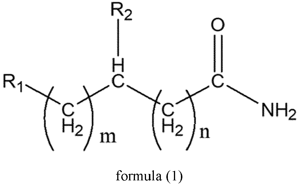
- R1 and R2 are each independently selected from hydrogen, -R, -NR2, -NHR, -NH2, - OH, -OR, -NHCOR, -OCOR, and -CH2COOH, where R represents a straight or branched chain alkyl group having 1-10 carbon atoms,
- m is an integer of 0 to 10; and
- n is an integer of 1 to 10; and

- The use of an amide as a passivation material has at least the following advantages: first, a nitrogen atom on the amide has a strong ability to bind protons, so it is not easy to generate harmful hydrogen vacancy during use, thereby ensuring stability of passivation and efficiency of a device; in addition, oxygen on the amide can be well anchored with lead in perovskite (if there is lead), which fixes the structure of an iodide-lead octahedron, so as to stabilize a perovskite phase. Second, due to p-π conjugation, the amide has a strong electron cloud density, which can stabilize a lithium ion and prevent the lithium ion from migrating into the perovskite, so as to reduce the adverse effect of migration of the lithium ion on the long-term stability of the device.
- In any embodiment, the passivation layer includes an amide cation of formula (3),

the passivation layer further includes an organic acid containing N, O, S and/or P, optionally N=O, S=O and/or P=O and/or a polymer of the organic acid, and/or an inorganic acid, and/or one or more anions thereof. - An anion has a certain influence on the passivation effect of an amide material in a perovskite solar cell. Although a common inorganic acid anion with high electronegativity can make up for the defect of an X site in perovskite (ABX3), it will reduce an electron cloud density at the amide due to the strong electronegativity, so that an effect of fixing a lithium ion by the amide declines. However, the inventors of the present application have found that an organic acid containing N, O, S and/or P or a polymer of the organic acid or some specific inorganic acids (such as phosphoric acid and sulfamic acid) is similar to a cation of the amide and has certain effects of passivating defects and stabilizing a perovskite phase; in addition, a lone pair of electrons on N, O, S, and P have a certain effect on fixing a lithium ion, which has a positive impact on the long-term stability of the device. Therefore, optionally, an organic acid containing N, O, S, and P, especially containing N=O, S=O, and P=O, or a polymer of the organic acid or some specific inorganic acids are used in the present application to prepare the passivation layer between the hole transport layer and the perovskite layer.
- In any embodiment, a ratio of a molar sum of the amide or the cation thereof to a molar sum of the organic acid and/or the polymer of the organic acid and/or the inorganic acid, and/or the anions thereof is 1:(1.0-1.5), optionally 1:(1.0-1.2).
- In any embodiment, the organic acid is selected from at least one of acetic acid, glycolic acid, oxalic acid, citric acid, ethylenediaminetetraacetic acid, maleic acid, acrylic acid, and organic phosphonic acid, and/or the inorganic acid is at least one selected from sulfamic acid and phosphoric acid.
- Using the above organic acid and/or inorganic acid to prepare the passivation layer between the hole transport layer and the perovskite layer can achieve better passivation of defects and stabilization of the perovskite phase.
- In any embodiment, the passivation layer includes one or more anions having the following structural formulas:


- In any embodiment, the passivation layer does not include a cyclic group, optionally does not include a benzene ring.
- This is because a group having a cyclic structure has a large pore diameter, so that a lithium ion can pass it through and enter the perovskite layer. In the perovskite solar cell described in the present application, the passivation layer between the hole transport layer and the perovskite layer adopts an alkyl chain instead of a group containing a cyclic structure, which can prevent the lithium ion from entering the perovskite layer through the passivation layer.
- In any embodiment, the hole transport layer includes 2,2',7,7'-tetrakis[N,N-di(4-methoxyphenyl)amino]-9,9'-spirobifluorene (Spiro-OMeTAD), optionally a weight content of the 2,2',7,7'-tetrakis[N,N-di(4-methoxyphenyl)amino]-9,9'-spirobifluorene is 60-95%, optionally 70-85%, based on a total weight of the entire hole transport layer.
- The passivation layer of the present application is especially suitable for use between the hole transport layer including the above Spiro-OMeTAD material and the perovskite layer.
- In any embodiment, the hole transport layer includes a lithium salt, optionally, the lithium salt is lithium bis(trifluoromethanesulfonyl)imide, more optionally, a weight content of the lithium salt is 5-30%, optionally 8-15%, based on a total weight of the entire hole transport layer.
- In a case that Spiro-OMeTAD is used as a hole transport material, since the material has a limited ability to conduct a hole, a lithium salt is usually added therein. However, solubility of the lithium salt in a solvent where Spiro-OMeTAD is present is low, so 4-tert-butylpyridine (tBP) is often added to increase its solubility. In addition, Spiro-OMeTAD may also be oxidized by adding a cobalt salt for oxidation to improve the ability of hole extraction. Optionally, the cobalt salt is tris[4-tert-butyl-2-(1H-pyrazol-1-yl)pyridine]cobalt (FK209 for short).
- In any embodiment, the perovskite solar cell is a formal perovskite solar cell. In the formal perovskite solar cell described in the present application, conductive glass, an electron transport layer, a perovskite layer, a passivation layer, a hole transport layer, and a back electrode (optionally a metal back electrode) are included successively, where the passivation layer is located between the perovskite layer and the hole transport layer. Optionally, the passivation layer may also be disposed between the electron transport layer and the perovskite layer.
- A second aspect of the present application provides a method for preparing a perovskite solar cell, the method including a step of preparing a hole transport layer, a step of preparing a perovskite layer, a step of preparing an electron transport layer, and a step of preparing a back electrode, where a passivation layer is disposed between the hole transport layer and the perovskite layer, and preparation of the passivation layer includes the following steps:
- step S1: preparing or making a passivation material ready, the passivation material including an amide and/or a cation thereof, where the amide includes a compound of formula (1) and/or formula (2):

- R1 and R2 are each independently selected from hydrogen, -R, -NR2, -NHR, -NH2, - OH, -OR, -NHCOR, -OCOR, and -CH2COOH, where R represents a straight or branched chain alkyl group having 1-10 carbon atoms,
- m is an integer of 0 to 10; and
- n is an integer of 1 to 10; and

- step S2: formulating a solution of the passivation material; and
- step S3: coating the solution of the passivation material on perovskite, and then performing annealing to obtain the passivation layer.
- Optionally, in the step S3, the passivation material is spread on a surface of the perovskite layer by spin coating. In some optional embodiments, a spin coating process includes spinning at a rotational speed of 1000-5000 rpm for 15-40s. In some optional embodiments, an annealing process includes raising temperature to 80-120°C and maintaining the annealing under the temperature for 5-30min.
- In any optional embodiment, the preparation of the passivation layer may include the following processes: the solution of the passivation material is added to the perovskite layer dropwise, and the passivation material is spread on a surface of the perovskite layer by spin coating, a spin coating process comprises spinning at a rotational speed of 1000-5000 rpm for 15-40s, and then the passivation material is placed in a vacuum environment for 5-20min, and a vacuum degree is optionally 0.01-0.2 MPa.
- In any optional embodiment, in the preparation of the passivation layer, no other passivation material is used except the passivation material prepared or made ready in the step S1.
- In any embodiment, the step S1 includes the following operations:
- (1) dissolving the amide in a solvent and performing stirring in an ice water bath; optionally, maintaining temperature at 0-4°C during stirring;
- (2) adding an organic acid, an inorganic acid and/or a polymer of the organic acid dropwise, optionally, continuing to react for 0.5-3h after finishing the adding dropwise; and
- (3) optionally, drying, washing and drying a reaction product in (2) to obtain the passivation material.
- In any embodiment, in the step S2, a solvent for formulating the solution of the passivation material is selected from one or more of ethanol, isopropanol, n-butanol, ethyl acetate, chloroform, chlorobenzene, ethyl butyrate, dichlorobenzene, diethyl ether, toluene, and xylene, optionally, a concentration of the solution of the passivation material for preparing the passivation layer is 0.2-2.5 mg/ml, optionally 0.5-2.0 mg/ml.
-
FIG. 1 is a schematic diagram of a structure of a perovskite solar cell prepared in Example 3 of the present application. In the figure, from bottom to top are successively: transparent conductive glass including a glass substrate and fluorine-doped tin oxide (FTO), from which light enters; an electron transport layer adopting tin oxide; a perovskite layer located between a passivation layer and the electron transport layer, in which a circle is used to represent an atom in the figure, and is schematically drawn; the passivation layer adopting a passivation material dodecylamide formate of the present application; a hole transport layer including a lithium ion, in which a circle represents the lithium ion; and a metal back electrode. - Hereinafter, embodiments specifically disclosing a solar cell of the present application will be described in detail with reference to drawings as appropriate. However, unnecessarily detailed descriptions may be omitted in some cases. For example, detailed description for a well-known matter and repeated description for a practically identical structure are omitted. This is done to avoid unnecessarily redundant descriptions for ease of understanding by persons skilled in the art. In addition, the drawings and the following description are provided for persons skilled in the art to fully appreciate the present application, and are not intended to limit the subject matters described in the claims.
- A "range" disclosed herein is defined in the form of a lower limit and an upper limit. A given range is defined by selecting a lower limit and an upper limit, and the selected lower limit and upper limit define boundaries of a particular range. The range defined in this manner may or may not include end values, and may be combined arbitrarily, that is, any lower limit may be combined with any upper limit to form a range. For example, if ranges of 60-120 and 80-110 are listed for a particular parameter, it is understood that ranges of 60-110 and 80-120 are also anticipated. In addition, if the minimum range values listed are 1 and 2, and the maximum range values listed are 3, 4 and 5, all the following ranges can be anticipated: 1-3, 1-4, 1-5, 2-3, 2-4, and 2-5. In the present application, unless otherwise specified, a numerical range "a-b" represents an abbreviated representation of any combination of real numbers between a and b, where both a and b are real numbers. For example, a numerical range "0-5" means that all real numbers between "0-5" have been listed herein, and "0-5" is just an abbreviated representation of a combination of these numerical values. In addition, when a certain parameter is expressed as an integer ≥2, it is equivalent to disclosing that the parameter is, for example, an integer 2, 3, 4, 5, 6, 7, 8, 9, 10, 11, 12, or the like.
- Unless otherwise specified, all embodiments and optional embodiments of the present application may be combined with each other to form a new technical solution.
- Unless otherwise specified, all technical features and optional technical features of the present application may be combined with each other to form a new technical solution.
- Unless otherwise specified, all steps of the present application may be performed sequentially or randomly, but preferably, performed sequentially. For example, a method includes steps (a) and (b), which means that the method may include steps (a) and (b) performed sequentially, or steps (b) and (a) performed sequentially. For example, the method mentioned may further include step (c), which means that step (c) may be added to the method in any order, for example, the method may include steps (a), (b) and (c), steps (a), (c) and (b), steps (c), (a) and (b), or the like.
- Unless otherwise specified, words "comprising" and "containing" mentioned in the present application are open-ended or closed-ended. For example, the words "comprising" and "containing" may mean that other components that are not listed may further be comprised or contained, or only listed components may be comprised or contained.
- In the present application, unless otherwise specified, the term "or" is inclusive. For example, the phrase "A or B" means "A, B or both A and B". More particularly, a condition "A or B" is satisfied by any one of the following: A is true (or present) and B is false (or not present); A is false (or not present) and B is true (or present); or both A and B are true (or present).
- In a perovskite solar cell of a formal structure, 2,2',7,7'-tetrakis[N,N-di(4-methoxyphenyl)amino]-9,9'-spirobifluorene (Spiro-OMeTAD) material is usually adopted to fabricate a hole transport layer, and a lithium salt is added therein. However, a perovskite solar cell prepared by adopting a Spiro-OMeTAD material as a hole transport layer and a conventional material for passivating defects on the surface of perovskite has poor long-term stability. According to the inventors' speculation, a reason for this problem may be that a lithium ion has a small radius and can easily pass through a common passivation material to enter a perovskite layer. However, after entering the perovskite layer, the lithium ion cannot enter a crystal lattice, but stays in a bulk phase of perovskite, which causes the migration of other ions, and makes the performance and stability of perovskite decline simultaneously.
- In view of the above problems, after in-depth research, the inventors of the present application propose a new passivation material, which can not only effectively passivate the surface defects of perovskite, but also prevent a lithium ion from passing through a passivation layer and entering a perovskite layer, thereby simultaneously ensuring the performance and long-term stability of a perovskite solar cell.
- Therefore, a first aspect of the present application provides a perovskite solar cell, including conductive glass, a hole transport layer, a perovskite layer, an electron transport layer and a back electrode, where a passivation layer is disposed between the hole transport layer and the perovskite layer, and the passivation layer includes an amide and/or a cation thereof, where the amide includes a compound of formula (1) and/or formula (2):

- Ri and R2 are each independently selected from hydrogen, -R, -NR2, -NHR, -NH2, - OH, -OR, -NHCOR, -OCOR, and -CH2COOH, where R represents a straight or branched chain alkyl group having 1-10 carbon atoms,
- m is an integer of 0 to 10; and
- n is an integer of 1 to 10; and

- In the present application, "a C5-C10 aryl or heteroaryl group" is an aryl or heteroaryl group having 5-10 carbon atoms, including, but not limited to, furan, thiophene, pyrrole, pyrazole, imidazole, triazole, tetrazole, oxazole, oxadiazole, oxatriazole, isothiazole, benzene, pyran, pyrone, thiopyran, pyridine, pyridazine, pyrimidine, pyrazine, piperidine, triazine, tetrazine, oxazine, indole, isoindole, indazole, benzimidazole, naphthalene, quinoline, isoquinoline, quinazoline, quinoxaline, pyridopyridine, etc.
- It should be understood that although R1 and R2 are defined above in the present application, the present application is not intended to be limited thereto. R1 and R2 may also be independently selected from another aliphatic hydrocarbon (such as another alkyl group having 10 or more carbon atoms), an alkenyl group (such as an alkenyl group having 1-10 carbon atoms), an alkynyl group (such as an alkynyl group having 1-10 carbon atoms), an aromatic hydrocarbon (such as benzene, alkylbenzene, halogen-substituted benzene, nitro-substituted benzene, and phenol), a saturated or unsaturated cyclic hydrocarbon (such as cyclopentane, cyclohexane, and cyclohexene) or a group of heterocyclic compound (such as pyridine, pyrimidine, thiophene, and furan), or condensed ring compound (such as naphthalene, phenanthrene, pyrene, carbazole, and fluorene). These are also all within the scope of the concept of the present application and are included in the disclosure scope of the present application.
- It should be understood that although the present application defines that the amide is the amide of formula (1) in some embodiments, the present application is not limited thereto. All possible amides (including the amide of formula (1) and other amides), amide polymers, amide derivatives, and any other substances from which the amides, the amide polymers, and the amide derivatives can be prepared (such as lactam) for a perovskite solar cell are all within the scope of the concept of the present application, and are also included in the disclosure scope of the present application, for example, but not limited to, the amide of formula (1), a derivative of the amide of formula (1), a polymer of the amide of formula (1), a hydrochloride of an amide, a cation of an amide, an anion of an amide, an alkene amide, an alkyne amide, an organophosphoramide, a polyamide, a polyolefin amide, a polyalkyne amide, or the like.
- Herein, "the amide described in the present application" covers all possible amides (including the amide of formula (1) and other amides), amide polymers, amide derivatives, and any other substances from which the amides, the amide polymers, and the amide derivatives can be prepared for a perovskite solar cell.
- In the present application, any substance including an "N-C(O)" group moiety is understood to be an amide covered by the present application.
- The amide described in the present application has at least two effects of passivating perovskite and preventing a molecule or ion with a small radius from passing through. Therefore, it should be understood that in any occasion where passivating perovskite and/or preventing a molecule or ion with a small radius from passing through is required, the amides, the amide polymers, the amide derivatives and any other substances (such as lactam) from which the amides, the amide polymers, and the amide derivatives can be prepared disclosed in the present application can be used.
- It should be understood that in the present application, the molecule or ion with the small radius may be selected as a lithium ion, but any other molecules or ions that can migrate to or pass through a layer material present in a perovskite solar cell are also included in the scope of the present application.
- Furthermore, it should be understood that all perovskite solar cells that use amides, amide polymers, amide derivatives, and any other substances from which the amides, the amide polymers, and the amide derivatives can be prepared (such as lactam) to passivate perovskite and/or prevent a molecule or ion with a small radius from migration are also within the scope of the concept of the present application and included in the disclosure scope of the present application.
- The structure of the perovskite solar cell described in the present application is introduced below, but the present application is not limited thereto.
- Conductive glass usually has a certain degree of transparency. Generally, transparent conductive glass is used. Conductive glass usually consists of a glass substrate and an oxide thin film (TCO for short) conductive layer. Conventionally used TCOs include indium tin oxide (ITO) and fluorine-doped tin oxide (FTO), but the present application is not limited thereto. Conductive glass needs to be cleaned before use, such as being cleaned with detergent, deionized water and ethanol in ultrasound.
- Conductive glass is used to conduct charge carriers out.
- An electron transport layer can be prepared by a conventional technical means in the art. For example, tin oxide may be used to prepare the electron transport layer.
- Optionally, a passivation layer may be disposed between the electron transport layer and a perovskite layer to passivate defects on an interface between the electron transport layer and the perovskite layer.
- A perovskite layer can be prepared by a conventional technical means in the art, and any perovskite used for preparing a solar cell in the art can be used.
- Perovskite used for preparing the perovskite layer may have a chemical formula ABX3, where A is methylamine (MA for short), formamidine (FA for short) or cesium (Cs), B is lead (Pb) or tin (Sn), optionally lead, and X is iodine (I) or bromine (Br).
- In some optional embodiments, a lead-containing perovskite layer system is chosen to be used.
- In some optional embodiments, a preparation method of the perovskite layer is as follows: irradiating a prepared battery preparation part optionally with an electron transport layer under UV for 15 minutes, adding 40-100 µL of perovskite solution on the battery preparation part (optionally, on the electron transport layer), optionally using a spin coater to spin at 1000-5000 rpm for 15-60s, adding 100-1000 µL of chlorobenzene dropwise during the spinning at the 10-30th second, and then continuing to spin the spin coater for 5-30s, and annealing a device at 80-180°C for 5-60min to obtain the perovskite layer.
- In some optional embodiments, the perovskite solution may be formulated by using formamidine iodide (FAI), lead iodide (PbI2), and chloromethylamine (MACl), and a solvent may be selected from N,N-dimethylformamide (DMF), dimethylsulfoxide (DMSO), N-methylpyrrolidone (NMP), γ-butyrolactone and a mixture thereof, but is not limited thereto. Optionally, in the perovskite solution, a concentration of the formamidine iodide (FAI) ranges from 0.8-1.5 mol/L, a concentration of the lead iodide (PbI2) ranges from 0.8-2 mol/L, and a concentration of the chloromethylamine (MACl) ranges from 5-50% (based on a total weight of the perovskite solution). Optionally, after the perovskite solution has been formulated, filtration is performed, and supernatant is taken for later use.
- In the perovskite solar cell described in the present application, a passivation layer is disposed between a hole transport layer and the perovskite layer, and the passivation layer includes an amide and/or a cation thereof described above.
- In the present application, a straight or branched chain alkyl group having 1-10 carbon atoms may be selected from, for example, methyl, ethyl, propyl, butyl, pentyl, hexyl, heptyl, octyl, nonyl, decyl, isopropyl, isobutyl, tert-butyl, isopentyl, tert-pentyl, neopentyl, 2-methylpentyl, 3-methylpentyl, 2,2-dimethylbutyl, 2,3-dimethylbutyl, 2-methylhexyl, 3-methylhexyl, 2,2-dimethylpentyl, 3,3-dimethylpentyl, 2,3-dimethyl pentyl, 2,4-dimethylpentyl, 3-ethylpentyl, 2,2,3-trimethylbutyl, 2-methylheptyl, 3-methylheptyl, 4-methyl heptyl, 2,2-dimethylhexane, 3,3-dimethylhexane, 2,3-dimethylhexane, 2,4-dimethylhexane, 2,5-dimethylhexane, 3,4-dimethylhexane, 3-ethylhexane, 2,2,3-trimethylpentane, 2,2,4-trimethylpentane, 2,3,3-trimethylpentane, 2,3,4-trimethylpentane, 2-methyl-3-ethylpentane, 3-methyl-3-ethylpentane, and 2,2,3,3-tetramethylbutane, but is not limited thereto.
- In addition to the above-mentioned effects, the use of an amide as a passivation material has at least the following advantages: first, a nitrogen atom on the amide has a strong ability to bind protons, so it is not easy to generate harmful hydrogen vacancy during use, thereby ensuring stability of passivation and efficiency of a device; in addition, oxygen on the amide can be well anchored with lead in perovskite (if there is lead), which fixes the structure of an iodide-lead octahedron, so as to stabilize a perovskite phase. Second, due to p-π conjugation, the amide has a strong electron cloud density, which can stabilize a lithium ion and prevent the lithium ion from migrating into the perovskite, so as to reduce the adverse effect of migration of the lithium ion on the long-term stability of the device.
- In some embodiments, the passivation layer includes an amide cation of formula (3),

- where R1, R2, m, and n are as defined above; and
- the passivation layer further includes an organic acid containing N, O, S and/or P, optionally N=O, S=O and/or P=O and/or a polymer of the organic acid, and/or an inorganic acid, and/or one or more anions thereof.
- It should be understood that although the present application defines the cation of the amide as the cation of formula (3) in some embodiments, the present application is not limited thereto. It should be understood that any amide described in the present application may or may not have a cation and be used in the passivation layer. In addition, a cation (H+) may be located at any chemically possible position of the amide described in the present application and may be one or two or more; in addition, the cation may be not only H+, but also one or more of any other cations that can introduce the cation of the amide described in the present application, and/or one or more of any other cations that can modify the amide described in the present application. In addition, in the present application, the amide may have an anion, and there is no limitation on the type and amount of the anion attached to the amide, as long as it can exist chemically.
- It should still be understood that although the present application defines an anion that may be used in the passivation layer in some embodiments, the present application is not limited thereto. All anions that can form an organic salt or an inorganic salt with the cation of the amide described in the present application and can be used for the perovskite solar cell are within the scope of the concept of the present application and are included in the disclosure scope of the present application. In addition, the anion described in the present application may also be one or more anions.
- An anion has a certain influence on the passivation effect of an amide material in a perovskite solar cell. Although a common inorganic acid anion with high electronegativity can make up for the defect of an X site in perovskite (ABX3), it will reduce an electron cloud density at the amide due to the strong electronegativity, so that an effect of fixing a lithium ion by the amide declines. However, the inventors of the present application have found that an organic acid containing N, O, S and/or P or a polymer of the organic acid or some specific inorganic acids (such as phosphoric acid and sulfamic acid) is similar to an amide cation and has certain effects of passivating defects and stabilizing a perovskite phase; in addition, a lone pair of electrons on N, O, S, and P have a certain effect on fixing a lithium ion, which has a positive impact on the long-term stability of the device. Therefore, optionally, an organic acid containing N, O, S, and P, especially containing N=O, S=O, and P=O, or a polymer of the organic acid or some specific inorganic acids are used in the present application to prepare the passivation layer between the hole transport layer and the perovskite layer.
- In some optional embodiments, the passivation layer between the hole transport layer and the perovskite layer is prepared only from the above-mentioned amide and/or amide cation and/or the above-mentioned anion.
- In some embodiments, the organic acid is selected from at least one of acetic acid, glycolic acid, oxalic acid, citric acid, ethylenediaminetetraacetic acid, maleic acid, acrylic acid, and organic phosphonic acid, and/or the inorganic acid is at least one selected from sulfamic acid and phosphoric acid.
- In the present application, the organic phosphonic acid is a substance containing a phosphonic acid group directly connected to a carbon atom in a molecule, that is, a substance containing the following structure in the molecule,

- Using the above organic acid and/or inorganic acid to prepare the passivation layer between the hole transport layer and the perovskite layer can achieve better passivation of defects and stabilization of the perovskite phase.
- In some embodiments, a ratio of a molar sum of the amide or the cation thereof to a molar sum of the organic acid and/or the polymer of the organic acid and/or the inorganic acid, and/or the anions thereof is 1:(1.0-1.5), optionally 1:(1.0-1.2).
- In some embodiments, the passivation layer includes one or more anions having the following structural formulas:


- It should be understood that although R3 and R4 are defined above in the present application, the present application is not intended to be limited thereto. R3 and R4 may also be independently selected from another aliphatic hydrocarbon (such as another alkyl group having 10 or more carbon atoms), an alkenyl group (such as an alkenyl group having 1-10 carbon atoms), an alkynyl group (such as an alkynyl group having 1-10 carbon atoms), an aromatic hydrocarbon (such as benzene, alkylbenzene, halogen-substituted benzene, nitro-substituted benzene, and phenol), a saturated or unsaturated cyclic hydrocarbon (such as cyclopentane, cyclohexane, and cyclohexene) or a group of heterocyclic compound (such as pyridine, pyrimidine, thiophene, and furan), or condensed ring compound (such as naphthalene, phenanthrene, pyrene, carbazole, and fluorene). These are also all within the scope of the concept of the present application and are included in the disclosure scope of the present application.
- In some optional embodiments, the amide may be selected from one or more of butanamide, valeramide, 3-methylbutanamide, dodecylamide, octanamide, and nicotinamide. In some optional embodiments, the organic acid is selected from one or more of acrylic acid, oxalic acid, 2-methylpropionic acid, acetic acid, and formic acid.
- In some embodiments, the passivation layer does not include a cyclic group, optionally does not include a cyclic group with a large pore diameter, such as a benzene ring.
- The cyclic group includes any saturated or unsaturated cyclic group. For example, a group having a cyclic structure includes, for example, an aromatic ring such as benzene ring, thiophene, and pyridine, and further, an aliphatic ring (such as cycloheptane), a cyclic ether, and the like.
- A group having a cyclic structure has a large pore diameter, so that a lithium ion can pass it through and enter the perovskite layer. In the perovskite solar cell described in the present application, the passivation layer between the hole transport layer and the perovskite layer adopts an alkyl chain instead of a group containing a cyclic structure, which can prevent the lithium ion from entering the perovskite layer through the passivation layer.
- It should be understood that in the present application, the passivation layer may only contain the amide described in the present application, especially the amide of formula (1).
- It should be understood that in the present application, the passivation layer may only contain the amide cation described in the present application and the anion described in the present application.
- It should also be understood that in the present application, the passivation layer may include and only include the amide described in the present application, the amide cation described in the present application, and the amide anion described in the present application at the same time. In this case, there is no restriction on the proportions of amounts of the amide described in the present application, the amide cation described in the present application and the amide anion described in the present application in the passivation layer, as long as it conforms to the chemical law and is suitable for use in a solar cell.
- It should still be understood that, in addition to the amide described in the present application, the amide cation described in the present application, and the amide anion described in the present application, the passivation layer may further include other materials that can be used in a solar cell, optionally other materials that do not contain a cyclic group, especially a benzene ring. In a case of including other materials, there is no restriction on the amount of the amide and the amount of the other materials described in the present application in the passivation layer, as long as it is suitable for use in a solar cell. In addition, in this case, there is also no restriction on the proportions of amounts of the amide described in the present application, the amide cation described in the present application and the amide anion described in the present application in the passivation layer, as long as it conforms to the chemical law and is suitable for use in a solar cell.
- A hole transport layer is used to collect and extract a hole from the perovskite layer.
- In some embodiments, the hole transport layer includes 2,2',7,7'-tetrakis[N,N-di(4-methoxyphenyl)amino]-9,9'-spirobifluorene (Spiro-OMeTAD), optionally a weight content of the 2,2',7,7'-tetrakis[N,N-di(4-methoxyphenyl)amino]-9,9'-spirobifluorene is 60-95%, optionally 70-85%, based on a total weight of the entire hole transport layer. It should be understood that although the present application defines the amount of Spiro-OMeTAD in the hole transport layer as the above-mentioned amount in some embodiments, the present application is not limited thereto. Other suitable amounts for use in a perovskite solar cell are also included within the disclosure scope of the present application.
- The passivation layer described in the present application is particularly suitable for use between the hole transport layer including the Spiro-OMeTAD material described above and the perovskite layer.
- In some embodiments, the hole transport layer includes, but is not limited to, a lithium salt, optionally, the lithium salt is lithium bis(trifluoromethanesulfonyl)imide, more optionally, a weight content of the lithium salt is 5-30%, optionally 8-15%, based on a total weight of the entire hole transport layer.
- It should be understood that in the present application, an effect of adding a lithium salt to a hole transport layer is the same as that of adding a lithium salt conventionally in the art. In addition, although the lithium salt is defined above in some embodiments, the present application does not limit the type and added amount of the lithium salt that can be used in the hole transport layer, as long as it can play a beneficial role.
- In a case that Spiro-OMeTAD is used as a hole transport material, since the material has a limited ability to conduct a hole, a lithium salt is usually added therein. However, solubility of the lithium salt in a solvent where Spiro-OMeTAD is present is low, so 4-tert-butylpyridine (tBP) is often added to increase its solubility. In addition, Spiro-OMeTAD may also be oxidized by adding a cobalt salt for oxidation to improve the ability of hole extraction. Optionally, the cobalt salt is tris[4-tert-butyl-2-(1H-pyrazol-1-yl)pyridine]cobalt (FK209).
- It should be understood that although the present application is studied for a perovskite solar cell in which 2,2',7,7'-tetrakis[N,N-di(4-methoxyphenyl)amino]-9,9'-spirobifluorene (Spiro- OMeTAD) material is used to make a hole transport layer and a lithium salt is added thereto, the present application is not limited thereto. The passivation material described in the present application is suitable for use together with any hole transport layer, perovskite layer and/or electron transport layer, or even other passivation layers where migration of a molecule or ion with a small radius may occur.
- It should be understood that although 2,2',7,7'-tetrakis[N,N-di(4-methoxyphenyl)amino]-9,9'-spirobifluorene (Spiro-OMeTAD ) may be selected as a material of a hole transport layer for a perovskite solar cell in the present application, any other hole transport layer materials in which the addition of a lithium salt is required or lithium ion migration will take place are also particularly suitable for use together with the passivation material described in the present application, and thus are also within the scope of the concept and disclosure scope of the present application.
- The hole transport layer can be prepared by a conventional technical means in the art.
- A back electrode may be a metal back electrode using a metal such as gold (Au), silver (Ag), and copper (Cu), but the present application is not limited thereto. The metal back electrode may be prepared by vapor deposition.
- In some embodiments, the perovskite solar cell is a formal perovskite solar cell. In the present application, a "formal" structure of the perovskite solar cell should be understood as a structure including conductive glass, an electron transport layer, a perovskite layer, a hole transport layer and a back electrode successively from a light incident surface. In the formal perovskite solar cell described in the present application, conductive glass, an electron transport layer, a perovskite layer, a passivation layer, a hole transport layer, and a back electrode (optionally a metal back electrode) are included successively, where the passivation layer is located between the perovskite layer and the hole transport layer. Optionally, the passivation layer may also be disposed between the electron transport layer and the perovskite layer.
- It should be understood that although the perovskite solar cell is defined as a formal structure in some embodiments, the present application is not limited thereto. A perovskite solar cell including the passivation material described in the present application is within the disclosure scope of the present application.
- A second aspect of the present application provides a method for preparing a perovskite solar cell, the method including a step of preparing a hole transport layer, a step of preparing a perovskite layer, and a step of preparing an electron transport layer, and a step of preparing a back electrode, where a passivation layer is disposed between the hole transport layer and the perovskite layer, and preparation of the passivation layer includes the following steps:
- step S1: preparing or making a passivation material ready, the passivation material including an amide and/or a cation thereof, where the amide includes a compound of formula (1) and/or formula (2):

- R1 and R2 are each independently selected from hydrogen, -R, -NR2, -NHR, -NH2, - OH, -OR, -NHCOR, -OCOR, and -CH2COOH, where R represents a straight or branched chain alkyl group having 1-10 carbon atoms,
- m is an integer of 0 to 10; and
- n is an integer of 1 to 10; and

- step S2: formulating a solution of the passivation material; and
- step S3: coating the solution of the passivation material on perovskite, and then performing annealing to obtain the passivation layer.
- Optionally, in the step S3, the passivation material is spread on a surface of the perovskite by spin coating. In some optional embodiments, a spin coating process includes spinning at a rotational speed of 1000-5000 rpm for 15-40s. In some optional embodiments, an annealing process includes raising temperature to 80-120°C and maintaining the annealing under the temperature for 5-30min.
- In some optional embodiments, the preparation of the passivation layer may include the following processes: the solution of the passivation material is added to the perovskite layer dropwise, and the passivation material is spread on a surface of the perovskite layer by spin coating, a spin coating process comprises spinning at a rotational speed of 1000-5000 rpm for 15-40s, and then the passivation material is placed in a vacuum environment for 5-20min, and a vacuum degree is optionally 0.01-0.2 MPa.
- It should be understood that although the present application specifies that the passivation material is added to the perovskite layer "dropwise", the present application is not limited thereto, and all methods that can achieve this purpose can be used, and are within the disclosure scope of the present application.
- In an optional embodiment, the method for preparing the perovskite solar cell includes a step of preparing a hole transport layer, a step of preparing a perovskite layer, a step of preparing an electron transport layer, and a step of preparing a back electrode, where a passivation layer is disposed between the hole transport layer and the perovskite layer, and preparation of the perovskite layer and the passivation layer includes the following steps:
- step S1: preparing or making a passivation material ready, the passivation material including an amide and/or a cation thereof, where the amide has a structure of formula (1):

- R1 and R2 are each independently selected from hydrogen, -R, -NR2, -NHR, -NH2, - OH, -OR, -NHCOR, -OCOR, and -CH2COOH, where R represents a straight or branched chain alkyl group having 1-10 carbon atoms,
- m is an integer of 0 to 10; and
- n is an integer of 1 to 10; and
- step S2' : formulating a perovskite solution, and formulating a solution of the passivation material, and
- step S3' : adding 40-100 µL of the perovskite solution dropwise on a battery preparation part with the electron transport layer prepared in the step of preparing the electron transport layer, and optionally using a spin coater to spin at 1000-5000 rpm for 15-40s, and adding 100-1000 µL of the prepared solution of the passivation material dropwise during spinning at 8-20th second; and then annealing the preparation part at 80-120°C for 5-30 minutes to obtain the battery preparation part with the perovskite layer and the passivation layer.
- In some optional embodiments, the passivation layer or the passivation material described in the step S1 includes an amide cation of formula (3),

- where R1, R2, m, and n are as defined above; and
- the passivation layer described in the step S1 further includes an organic acid containing N, O, S and/or P, optionally N=O, S=O and/or P=O and/or a polymer of the organic acid, and/or an inorganic acid, and/or one or more anions thereof.
- Optionally, in the step S1, the passivation material may be obtained commercially.
- In some embodiments, in the preparation of the passivation layer, no other passivation material is used except the passivation material used in the step S1.
- In some optional embodiments, the step S1 includes the following operations: dissolving the amide in a solvent and performing stirring, and adding the organic acid and/or the polymer of the organic acid, and/or the inorganic acid; optionally, the stirring is carried out in an ice water bath, and optionally, temperature of the stirring is maintained at 0-4°C during the stirring. In some optional embodiments, reaction in the step S1 is carried out for 0.5-3h.
- In some optional embodiments, in the step S1, a ratio of a molar sum of the amide to a molar sum of the organic acid and/or the polymer of the organic acid and/or the inorganic acid is 1:(1.0-1.5), optionally 1:(1.0-1.2). Controlling the amount of the amide to be equal to or less than the molar weight of the organic acid and/or the polymer of the organic acid, and/or the inorganic acid is more conducive to treatment after the reaction.
- In some embodiments, the step S1 includes the following operations:
- (1) dissolving the amide in a solvent and performing stirring in an ice water bath; optionally, maintaining temperature at 0-4°C during stirring;
- (2) adding an organic acid, an inorganic acid and/or a polymer of the organic acid dropwise, optionally, continuing to react for 0.5-3h after finishing the adding dropwise; and
- (3) optionally, drying, washing and drying a reaction product in (2) to obtain the passivation material.
- In some optional embodiments, after the reaction is finished, the solvent is evaporated, washed and dried; optionally, the solvent is spin-dried by rotary evaporation; and optionally, diethyl ether or ethyl acetate is used for washing.
- In some embodiments, in the step S2, a solvent for formulating the solution of the passivation material is selected from one or more of ethanol, isopropanol, n-butanol, ethyl acetate, chloroform, chlorobenzene, ethyl butyrate, dichlorobenzene, diethyl ether, toluene, and xylene, optionally, a concentration of the solution of the passivation material for preparing the passivation layer is 0.2-2.5 mg/ml, optionally 0.5-2.0 mg/ml.
- In some optional embodiments, in the step S3, the solution of the passivation material is added to the perovskite layer dropwise, and then spin-coated statically or dynamically; after the spin coating is completed, optionally, the battery preparation part coated with the passivation material is annealed, and the annealing process is as follows: temperature is raised to 60-150°C, optionally 80-120°C, and maintained for a period of 5-30min, optionally 8-15min to obtain the battery preparation part with the passivation layer.
- It should be understood that although the present application provides a preparation method of a perovskite solar cell and a preparation method of a passivation material in some embodiments, the present application is not limited thereto. Any method for preparing a passivation material of the present application and any method for preparing a perovskite solar cell including the passivation material of the present application are all within the disclosure scope of the present application.
- Hereinafter, examples of the present application will be explained. The examples described below are exemplary and are merely for explaining the present application, and should not be construed as limiting the present application. Techniques or conditions that are not specified in examples are according to the techniques or conditions described in documents in the art or the product specification. Reagents or instruments used without being marked with the manufacturer are conventional products that are commercially available.
- For specific preparation process, reference may be made to Table 1.
- Conductive glass with a fluorine-doped tin oxide (FTO) film, which is commercially available, can be directly used after cleaning.
- A 15% tin oxide aqueous solution and deionized water were mixed in 1:3, and stirred at room temperature for 1h, and 70 µL was taken to be spin-coated on a surface of FTO conductive glass for heating at 150°C for 15min to obtain a battery preparation part with an electron transport layer.
- Formulation of a perovskite solution: 80 mg of formamidine iodide (FAI), 223 mg of lead iodide (PbI2), and 15 mg of chloromethylamine (MACI) were dissolved in 1 mL of a solvent. The solvent was a mixed solvent of N,N-dimethylformamide (DMF) and dimethyl sulfoxide (DMSO), where a volume ratio of DMF to DMSO was 4:1 (DMF: DMSO). The perovskite solution was stirred at room temperature for 1h with a magnetic stirrer and filtered, and supernatant was taken for later use.
- Formamidine iodide (FAI), lead iodide (PbI2) and chloromethylamine (MACI) were purchased from Xi'an Polymer Light Technology Corp., and DMF and DMSO were purchased from Sigma Corporation.
- The battery preparation part with the electron transport layer obtained in the previous step was irradiated under UV for 15 minutes, and then 60 µL of the perovskite supernatant was added to the electron transport layer, and spinned for 30s with a spin coater, and 300 µL of chlorobenzene was added dropwise at 15th second, and then the spin coater continued to spin for 15s, and the device was placed on a 100°C hot plate for annealing for 10min to obtain the battery preparation part having the electron transport layer and the perovskite layer successively.
- Formulation of a solution of a passivation material: isopropanol was used as a solvent, and the passivation material prepared in the step 1 was used. See Table 2 for the specific concentration.
- The battery preparation part with the electron transport layer and the perovskite layer prepared in the previous step was placed on a spin coater, and then 60 µL of the formulated isopropanol solution of the passivation material was added dropwise to the perovskite layer, and spin-coated for 30s, and then the device was placed on a 100°C hot plate for annealing for 10min to obtain the battery preparation part having the electron transport layer, the perovskite layer and the passivation layer successively.
- Lithium bis(trifluoromethanesulfonyl)imide (Li-TFSI), 4-tert-butylpyridine (tBP), and tri(1,1,1-trifluoro-N-[(trifluoromethyl)sulfonyl]methanesulfonamide salt) (FK209) were added to Spiro-OMeTAD.
- The specific process is as follows:
- (1) formulating a Li-TFSI solution of which a solvent is acetonitrile, and a concentration is 520 mg/mL, and performing dissolution in ultrasound for 10min for later use;
- (2) formulating a FK209 solution of which a solvent is acetonitrile, and a concentration is 300mg/mL;
- (3) formulating a chlorobenzene solution of 2,2',7,7'-tetrakis[N,N-di(4-methoxyphenyl)amino]-9,9'-spirobifluorene (Spiro-OMeTAD) with a concentration of 73 mg/mL, and performing dissolution in ultrasonic for 10min; and
- (4) adding 18 µL of the Li-TFSI solution, 30 µL of tBP and 29 µL of the FK209 solution to 1 mL of the chlorobenzene solution of Spiro-OMeTAD, performing stirring for 1h, and then filtration for later use, to obtain a Spiro-OMeTAD solution.
- 60 µL of the lithium containing Spiro-OMeTAD solution was added dropwise to the passivation layer prepared in the previous step, and spin-coated at 3000 rpm for 30s to obtain a hole transport layer.
- According to a mask pattern, a razor blade was used to scrape part of functional layers (including the hole transport layer, the perovskite layer, the passivation layer, the electron transport layer, and a buffer layer) of the battery preparation part having conductive glass, the electron transport layer, the perovskite layer, the passivation layer and the hole transport layer successively prepared in the previous step to expose a conductive glass layer, and then residual functional layers were wiped off with a cleaning solution. The preparation part was put into an evaporation mask, and 80 nm silver was evaporated and plated at the exposed conductive glass in a vacuum evaporation device, with an evaporation rate of 0.1 A/s. A complete perovskite solar cell was obtained after evaporation.
- A structure diagram of the prepared perovskite solar cell is shown in
FIG. 1 . - Examples 1-2 were carried out in a manner similar to Example 3, except that step 1 was omitted, and a passivation layer in step 2 used valeramide and hexanamide respectively. The two substances were purchased from Aladdin Company.
- Examples 4-5 were carried out in a manner similar to Example 3, except the prepation of a passivation material in step 1, see Table 1.
- Comparative Example 1 was carried out in a manner similar to Example 1, except that step 1 was omitted and a passivation layer in step 2 used phenylethylamine.
Table 1: Preparation of Passivation Material Passivation material Synthesis method Post-treatment method Example 3 dodecylamide formate dissolving dodecylamide in absolute ethanol, performing stirring in an ice water bath to maintain temperature at 0-4°C, adding formic acid dropwise (a molar ratio of dodecylamide to formic acid is 1:1.1), and continuing to react for 0.5-3h after the adding dropwise spinning the solvent dry, washing it with ether for many times, and putting it into an oven for drying at 60°C for 3h Example 4 octylamide acetate dissolving octylamide in absolute ethanol, performing stirring in an ice water bath to maintain temperature at 0-4°C, adding acetic acid dropwise (a molar ratio of octylamide to acetic acid is 1:1.1), and continuing to react for 0.5-3h after the adding dropwise spinning the solvent dry, washing it with ether for many times, and putting it into an oven for drying at 60°C for 3h Example 5 niacinamide acrylate dissolving nicotinamide in absolute ethanol, performing stirring in an ice water bath to maintain temperature at 0-4°C, adding acrylic acid dropwise (a molar ratio of nicotinamide to acrylic acid is 1:1.1), and continuing to react for 0.5-3h after the adding dropwise spinning the solvent dry, washing it with ether for many times, and putting it into an oven for drying at 60°C for 3h - Test was carried out according to the national standard IEC61215, in which the test was carried out under the condition of light illumination, and using a digital source meter, where a light source was provided by a solar simulator, and light emitted by the light source conforms to AM 1.5G standard solar spectrum.
- Photoelectric conversion efficiency of a perovskite solar cell prepared in Examples and Comparative Example was measured on the 3rd day and the 30th day, respectively.
Table 2: Performance Test Results Passivation material Concentration (mg/mL) Efficiency on the 3rd day (%) Efficiency on the 30th day (%) Comparative Example 1 p-fluorophenyl ethyl amine 0.0 19.01 18.52 0.5 19.55 19.35 1.0 19.62 19.44 1.5 19.21 19.01 2.0 18.89 18.72 Example 1 valeramide 0.5 19.85 19.95 1.0 20.01 20.06 1.5 19.66 19.80 2.0 18.85 18.91 Example 2 hexanamide 0.5 19.92 20.05 1.0 20.21 20.12 1.5 19.65 19.66 2.0 18.55 18.56 Example 3 dodecylamide formiate 0.5 21.88 22.01 1.0 22.03 22.32 1.5 22.32 22.68 2.0 21.01 21.56 Example 4 octylamide acetate 0.5 21.65 21.88 1.0 21.42 21.56 1.5 22.01 22.55 2.0 20.12 21.01 Example 5 niacinamide acrylate 0.5 21.88 21.66 1.0 21.65 21.56 1.5 22.09 21.77 2.0 21.53 21.38 - It can be seen from Table 2 that, compared with preparing a passivation layer between a hole transport layer and a perovskite layer with p-fluorophenylethylamine in Comparative Example 1, preparing a passivation layer with 0.5-2.0mg/ml, especially 0.5-1.5mg/ml of an amide or an amide cation described in the present application can significantly improve photoelectric conversion efficiency of a perovskite solar cell, especially long-term stability. In addition, it can also be seen that in Example 5, photoelectric conversion efficiency of a perovskite solar cell obtained by preparing a passivation layer with niacinamide acrylate containing a cyclic group is higher, but long-term stability is slightly reduced compared with Examples 1-4.
- It should be noted that the present application is not limited to the foregoing embodiments. The foregoing embodiments are merely examples, and embodiments having substantially the same constitution as the technical idea and exerting the same effects within the technical solution of the present application are all included within the technical scope of the present application. In addition, various modifications made to the embodiments that are easily thought of by persons skilled in the art without departing from the spirit of the present application, and other embodiments that are constructed by combining some of the constituent elements of the embodiments are also included in the scope of the present application.
Claims (14)
- A perovskite solar cell, comprising conductive glass, a hole transport layer, a perovskite layer, an electron transport layer and a back electrode, wherein a passivation layer is disposed between the hole transport layer and the perovskite layer, and the passivation layer comprises an amide and/or a cation thereof, wherein the amide comprises a compound of formula (1) and/or formula (2):
 R1 and R2 are each independently selected from hydrogen, -R, -NR2, -NHR, -NH2, -OH, -OR, -NHCOR, -OCOR, and -CH2COOH, wherein R represents a straight or branched chain alkyl group having 1-10 carbon atoms,m is an integer of 0 to 10; andn is an integer of 1 to 10; and

- The perovskite solar cell according to claim 1, wherein the passivation layer comprises an amide cation of formula (3),
 wherein R1, R2, m, and n are as defined in claim 1; andthe passivation layer further comprises an organic acid containing N, O, S and/or P, optionally N=O, S=O and/or P=O and/or a polymer of the organic acid, and/or an inorganic acid, and/or one or more anions thereof.
- The perovskite solar cell according to claim 2, wherein the organic acid is selected from at least one of acetic acid, glycolic acid, oxalic acid, citric acid, ethylenediaminetetraacetic acid, maleic acid, acrylic acid, and organic phosphonic acid, and/or the inorganic acid is at least one selected from sulfamic acid and phosphoric acid.
- The perovskite solar cell according to claim 2 or 3, wherein a ratio of a molar sum of the amide or the cation thereof to a molar sum of the organic acid and/or the polymer of the organic acid and/or the inorganic acid, and/or the anions thereof is 1:(1.0-1.5), optionally 1:(1.0-1.2).
- The perovskite solar cell according to any one of claims 1-4, wherein the passivation layer comprises one or more anions having the following structural formulas:


- The perovskite solar cell according to any one of claims 1-5, wherein the passivation layer does not comprise a cyclic group, optionally does not comprise a benzene ring.
- The perovskite solar cell according to any one of claims 1-6, wherein the hole transport layer comprises 2,2',7,7'-tetrakis[N,N-di(4-methoxyphenyl)amino]-9,9'-spirobifluorene, optionally a weight content of the 2,2',7,7'-tetrakis[N,N-di(4-methoxyphenyl)amino]-9,9'-spirobifluorene is 60-95%, optionally 70-85%, based on a total weight of the entire hole transport layer.
- The perovskite solar cell according to any one of claims 1-7, wherein the hole transport layer comprises a lithium salt, optionally, the lithium salt is lithium bis(trifluoromethanesulfonyl)imide, more optionally, a weight content of the lithium salt is 5-30%, optionally 8-15%, based on a total weight of the entire hole transport layer.
- The perovskite solar cell according to any one of claims 1-8, wherein the perovskite solar cell is a formal perovskite solar cell.
- A method for preparing a perovskite solar cell, the method comprising a step of preparing a hole transport layer, a step of preparing a perovskite layer, a step of preparing an electron transport layer, and a step of preparing a back electrode, wherein a passivation layer is disposed between the hole transport layer and the perovskite layer, and preparation of the passivation layer comprises the following steps:step S1: preparing or making a passivation material ready, the passivation material comprising an amide and/or a cation thereof, wherein the amide comprises a compound of formula (1) and/or formula (2):
 R1 and R2 are each independently selected from hydrogen, -R, -NR2, -NHR, -NH2, -OH, -OR, -NHCOR, -OCOR, and -CH2COOH, wherein R represents a straight or branched chain alkyl group having 1-10 carbon atoms,m is an integer of 0 to 10; andn is an integer of 1 to 10; and
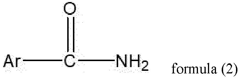 step S2: formulating a solution of the passivation material; andstep S3: coating the solution of the passivation material on perovskite, and then performing annealing to obtain the passivation layer.
- The method for preparing the perovskite solar cell according to claim 10, wherein in the preparation of the passivation layer, no other passivation material is used except the passivation material prepared in the step S1.
- The method for preparing the perovskite solar cell according to claim 10 or 11, wherein the step S1 comprises the following operations:(1) dissolving the amide in a solvent and performing stirring in an ice water bath; optionally, maintaining temperature at 0-4°C during stirring;(2) adding an organic acid, an inorganic acid and/or a polymer of the organic acid dropwise, optionally, continuing to react for 0.5-3h after finishing the adding dropwise; and(3) optionally, drying, washing and drying a reaction product in (2) to obtain the passivation material.
- The method for preparing the perovskite solar cell according to any one of claims 10-12, wherein in the step S2, a solvent for formulating the solution of the passivation material is selected from one or more of ethanol, isopropanol, n-butanol, ethyl acetate, chloroform, chlorobenzene, ethyl butyrate, dichlorobenzene, diethyl ether, toluene, and xylene, optionally, a concentration of the solution of the passivation material for preparing the passivation layer is 0.2-2.5 mg/ml, optionally 0.5-2.0 mg/ml.
- The method for preparing the perovskite solar cell according to any one of claims 10-13, wherein in the step S3, the solution of the passivation material is added to the perovskite layer, and the passivation material is spread on a surface of the perovskite layer by spin coating, a spin coating process comprises spinning at a rotational speed of 1000-5000 rpm for 15-40s, and then the passivation material is placed in a vacuum environment for 5-20min, and a vacuum degree is optionally 0.01-0.2 MPa.
Applications Claiming Priority (1)
| Application Number | Priority Date | Filing Date | Title |
|---|---|---|---|
| PCT/CN2022/078287 WO2023159564A1 (en) | 2022-02-28 | 2022-02-28 | Perovskite solar cell |
Publications (3)
| Publication Number | Publication Date |
|---|---|
| EP4266349A1 true EP4266349A1 (en) | 2023-10-25 |
| EP4266349A4 EP4266349A4 (en) | 2024-04-03 |
| EP4266349B1 EP4266349B1 (en) | 2025-01-01 |
Family
ID=87764374
Family Applications (1)
| Application Number | Title | Priority Date | Filing Date |
|---|---|---|---|
| EP22919281.0A Active EP4266349B1 (en) | 2022-02-28 | 2022-02-28 | Perovskite solar cell |
Country Status (5)
| Country | Link |
|---|---|
| US (1) | US11917904B2 (en) |
| EP (1) | EP4266349B1 (en) |
| CN (1) | CN118266281A (en) |
| ES (1) | ES3017815T3 (en) |
| WO (1) | WO2023159564A1 (en) |
Families Citing this family (9)
| Publication number | Priority date | Publication date | Assignee | Title |
|---|---|---|---|---|
| CN118084713A (en) * | 2024-02-29 | 2024-05-28 | 正泰新能科技股份有限公司 | A multifunctional molecular additive for perovskite solar cells and its preparation method and application |
| CN118510356B (en) * | 2024-07-15 | 2024-12-06 | 无锡众能光储科技有限公司 | A perovskite film, preparation method and application thereof in perovskite solar cells |
| CN119384143B (en) * | 2024-09-18 | 2025-10-10 | 南开大学 | A method for preparing perovskite solar cells based on passivation of nicotinamide derivative materials |
| WO2026079872A1 (en) * | 2024-10-08 | 2026-04-16 | 한양대학교 산학협력단 | Perovskite crystal having cations of different types and anionic organic molecules, method for manufacturing thin film comprising same, and electronic device comprising thin film |
| CN118922002B (en) * | 2024-10-10 | 2025-03-18 | 安徽华晟新能源科技股份有限公司 | Photovoltaic cell and method for making the same |
| CN119569647B (en) * | 2024-12-02 | 2026-04-03 | 厦门紫金新能源新材料科技有限公司 | A buried substrate compound and its application in perovskite solar cells |
| CN122161280A (en) * | 2024-12-03 | 2026-06-05 | 宁德时代新能源科技股份有限公司 | Perovskite solar cell, preparation method thereof and electric equipment |
| CN120826146B (en) * | 2025-09-08 | 2025-11-18 | 中矿资源(天津)新材料有限公司 | Perovskite solar cell based on pyridine thioether derivative passivation and preparation method thereof |
| CN122094296B (en) * | 2026-04-22 | 2026-08-11 | 正泰新能科技股份有限公司 | An interface passivation layer, its preparation method, and perovskite solar cells |
Family Cites Families (8)
| Publication number | Priority date | Publication date | Assignee | Title |
|---|---|---|---|---|
| CN110061139B (en) | 2013-12-17 | 2023-04-18 | 牛津大学科技创新有限公司 | Photovoltaic device comprising metal halide perovskite and passivating agent |
| CN108258128B (en) * | 2018-01-17 | 2020-09-04 | 杭州纤纳光电科技有限公司 | A kind of perovskite solar cell with interface modification layer and preparation method thereof |
| CN110518127B (en) * | 2019-08-16 | 2021-03-09 | 上海交通大学 | Perovskite solar cell based on surfactant passivation and preparation method |
| CN110635039B (en) * | 2019-08-21 | 2021-01-26 | 厦门大学 | A method of passivating perovskite and perovskite solar cell |
| CN112582543B (en) * | 2019-09-30 | 2023-05-02 | 上海黎元新能源科技有限公司 | Perovskite solar cell |
| CN112864325B (en) | 2019-11-26 | 2024-03-29 | 中国石油大学(华东) | Method for passivating perovskite film on surface of multifunctional triphenylamine molecule |
| CN111628086B (en) * | 2020-06-15 | 2022-05-17 | 西南石油大学 | Vitamin organic substance modified perovskite solar cell and preparation method thereof |
| CN114014840B (en) * | 2021-11-17 | 2023-12-26 | 常州大学 | Pyridyl-containing organic molecular material and application thereof in perovskite solar cell |
-
2022
- 2022-02-28 CN CN202280078003.XA patent/CN118266281A/en active Pending
- 2022-02-28 ES ES22919281T patent/ES3017815T3/en active Active
- 2022-02-28 WO PCT/CN2022/078287 patent/WO2023159564A1/en not_active Ceased
- 2022-02-28 EP EP22919281.0A patent/EP4266349B1/en active Active
-
2023
- 2023-07-12 US US18/220,832 patent/US11917904B2/en active Active
Also Published As
| Publication number | Publication date |
|---|---|
| WO2023159564A1 (en) | 2023-08-31 |
| CN118266281A (en) | 2024-06-28 |
| US11917904B2 (en) | 2024-02-27 |
| US20230354696A1 (en) | 2023-11-02 |
| ES3017815T3 (en) | 2025-05-13 |
| EP4266349B1 (en) | 2025-01-01 |
| EP4266349A4 (en) | 2024-04-03 |
Similar Documents
| Publication | Publication Date | Title |
|---|---|---|
| EP4266349B1 (en) | Perovskite solar cell | |
| CN118251022B (en) | Inverse type wide-bandgap perovskite solar cell and preparation method thereof | |
| CN112349842B (en) | Lead-tin blended perovskite film and preparation method and application thereof | |
| CN116322079A (en) | A kind of solar cell device and its preparation method and application | |
| CN117156884A (en) | Multifunctional molecule modified perovskite solar cell and preparation method thereof | |
| CN118540959A (en) | Ionic liquid, precursor, perovskite light-absorbing layer and preparation method, perovskite solar cell and electrical equipment | |
| CN116715599A (en) | An additive for perovskite solar cells and perovskite solar cells | |
| CN114373870B (en) | A method for improving electron transfer efficiency at the interface of tin dioxide-lead halide perovskite | |
| CN118234356A (en) | Organic electronic transmission material and perovskite photovoltaic device | |
| CN119300615A (en) | A perovskite solar cell and a method for preparing the same | |
| CN114716469B (en) | Undoped organic micromolecular hole transport material and preparation method and application thereof | |
| CN117979711A (en) | All-inorganic CsPbIBr modified based on polyethylene glycol derivative2Perovskite solar cell and preparation method and application thereof | |
| Sun et al. | Interfacial modification by 2-fluoroisonicotinic acid enabling high-efficiency and stable nip perovskite solar cells | |
| CN114497379A (en) | Method for improving energy conversion efficiency and stability of organic-inorganic hybrid perovskite solar cell | |
| CN121038503B (en) | Hole transport layer, preparation method thereof, perovskite solar cell and electricity utilization device | |
| CN119173115B (en) | A method for passivating defects in perovskite films and its application | |
| CN117430546A (en) | A three-dimensional stacked doping-free hole transport material and its preparation method and application, perovskite solar cells | |
| WO2025124377A1 (en) | Solar cell, interface passivation material, photovoltaic power generation system and electric device | |
| LIU et al. | Electrochemical Performance Study of Solar Cells Made of the Perovskite Material. | |
| CN121850896A (en) | Passivation material for perovskite thin film, perovskite solar cell and preparation method | |
| CN118450776A (en) | A perovskite solar cell modified by double Schiff base compounds and preparation method thereof | |
| CN121057482A (en) | Precursor solution for preparing perovskite photovoltaic modules and preparation method | |
| CN121941193A (en) | Modified tin-containing perovskite solar cell doped with polyphenol derivative and preparation method thereof | |
| CN121463643A (en) | Perovskite solar cell and preparation method and application thereof | |
| CN118515669A (en) | An organic electron transport material and its use, a perovskite solar cell and its preparation method |
Legal Events
| Date | Code | Title | Description |
|---|---|---|---|
| STAA | Information on the status of an ep patent application or granted ep patent |
Free format text: STATUS: UNKNOWN |
|
| STAA | Information on the status of an ep patent application or granted ep patent |
Free format text: STATUS: THE INTERNATIONAL PUBLICATION HAS BEEN MADE |
|
| PUAI | Public reference made under article 153(3) epc to a published international application that has entered the european phase |
Free format text: ORIGINAL CODE: 0009012 |
|
| STAA | Information on the status of an ep patent application or granted ep patent |
Free format text: STATUS: REQUEST FOR EXAMINATION WAS MADE |
|
| 17P | Request for examination filed |
Effective date: 20230728 |
|
| AK | Designated contracting states |
Kind code of ref document: A1 Designated state(s): AL AT BE BG CH CY CZ DE DK EE ES FI FR GB GR HR HU IE IS IT LI LT LU LV MC MK MT NL NO PL PT RO RS SE SI SK SM TR |
|
| REG | Reference to a national code |
Ref country code: DE Ref legal event code: R079 Free format text: PREVIOUS MAIN CLASS: H01L0021020000 Ipc: H10K0030400000 Ref country code: DE Ref legal event code: R079 Ref document number: 602022009439 Country of ref document: DE Free format text: PREVIOUS MAIN CLASS: H01L0021020000 Ipc: H10K0030400000 |
|
| A4 | Supplementary search report drawn up and despatched |
Effective date: 20240301 |
|
| RIC1 | Information provided on ipc code assigned before grant |
Ipc: H10K 30/86 20230101ALN20240226BHEP Ipc: H01L 31/02 20060101ALN20240226BHEP Ipc: H10K 71/12 20230101ALI20240226BHEP Ipc: H10K 85/50 20230101ALI20240226BHEP Ipc: H10K 30/40 20230101AFI20240226BHEP |
|
| RIC1 | Information provided on ipc code assigned before grant |
Ipc: H10K 30/86 20230101ALN20240814BHEP Ipc: H01L 31/02 20060101ALN20240814BHEP Ipc: H10K 30/88 20230101ALI20240814BHEP Ipc: H10K 71/12 20230101ALI20240814BHEP Ipc: H10K 85/50 20230101ALI20240814BHEP Ipc: H10K 30/40 20230101AFI20240814BHEP |
|
| RAP1 | Party data changed (applicant data changed or rights of an application transferred) |
Owner name: CONTEMPORARY AMPEREX TECHNOLOGY(HONG KONG) LIMITED |
|
| GRAP | Despatch of communication of intention to grant a patent |
Free format text: ORIGINAL CODE: EPIDOSNIGR1 |
|
| STAA | Information on the status of an ep patent application or granted ep patent |
Free format text: STATUS: GRANT OF PATENT IS INTENDED |
|
| RIC1 | Information provided on ipc code assigned before grant |
Ipc: H10K 30/86 20230101ALN20240910BHEP Ipc: H01L 31/02 20060101ALN20240910BHEP Ipc: H10K 30/88 20230101ALI20240910BHEP Ipc: H10K 71/12 20230101ALI20240910BHEP Ipc: H10K 85/50 20230101ALI20240910BHEP Ipc: H10K 30/40 20230101AFI20240910BHEP |
|
| INTG | Intention to grant announced |
Effective date: 20241004 |
|
| GRAS | Grant fee paid |
Free format text: ORIGINAL CODE: EPIDOSNIGR3 |
|
| GRAA | (expected) grant |
Free format text: ORIGINAL CODE: 0009210 |
|
| STAA | Information on the status of an ep patent application or granted ep patent |
Free format text: STATUS: THE PATENT HAS BEEN GRANTED |
|
| AK | Designated contracting states |
Kind code of ref document: B1 Designated state(s): AL AT BE BG CH CY CZ DE DK EE ES FI FR GB GR HR HU IE IS IT LI LT LU LV MC MK MT NL NO PL PT RO RS SE SI SK SM TR |
|
| DAV | Request for validation of the european patent (deleted) | ||
| DAX | Request for extension of the european patent (deleted) | ||
| REG | Reference to a national code |
Ref country code: GB Ref legal event code: FG4D |
|
| REG | Reference to a national code |
Ref country code: DE Ref legal event code: R096 Ref document number: 602022009439 Country of ref document: DE |
|
| REG | Reference to a national code |
Ref country code: CH Ref legal event code: EP |
|
| REG | Reference to a national code |
Ref country code: IE Ref legal event code: FG4D |
|
| P01 | Opt-out of the competence of the unified patent court (upc) registered |
Free format text: CASE NUMBER: APP_1294/2025 Effective date: 20250109 |
|
| REG | Reference to a national code |
Ref country code: LT Ref legal event code: MG9D |
|
| REG | Reference to a national code |
Ref country code: NL Ref legal event code: MP Effective date: 20250101 |
|
| REG | Reference to a national code |
Ref country code: ES Ref legal event code: FG2A Ref document number: 3017815 Country of ref document: ES Kind code of ref document: T3 Effective date: 20250513 |
|
| REG | Reference to a national code |
Ref country code: AT Ref legal event code: MK05 Ref document number: 1757666 Country of ref document: AT Kind code of ref document: T Effective date: 20250101 |
|
| PG25 | Lapsed in a contracting state [announced via postgrant information from national office to epo] |
Ref country code: NL Free format text: LAPSE BECAUSE OF FAILURE TO SUBMIT A TRANSLATION OF THE DESCRIPTION OR TO PAY THE FEE WITHIN THE PRESCRIBED TIME-LIMIT Effective date: 20250101 |
|
| PG25 | Lapsed in a contracting state [announced via postgrant information from national office to epo] |
Ref country code: FI Free format text: LAPSE BECAUSE OF FAILURE TO SUBMIT A TRANSLATION OF THE DESCRIPTION OR TO PAY THE FEE WITHIN THE PRESCRIBED TIME-LIMIT Effective date: 20250101 |
|
| PG25 | Lapsed in a contracting state [announced via postgrant information from national office to epo] |
Ref country code: PL Free format text: LAPSE BECAUSE OF FAILURE TO SUBMIT A TRANSLATION OF THE DESCRIPTION OR TO PAY THE FEE WITHIN THE PRESCRIBED TIME-LIMIT Effective date: 20250101 |
|
| PG25 | Lapsed in a contracting state [announced via postgrant information from national office to epo] |
Ref country code: IS Free format text: LAPSE BECAUSE OF FAILURE TO SUBMIT A TRANSLATION OF THE DESCRIPTION OR TO PAY THE FEE WITHIN THE PRESCRIBED TIME-LIMIT Effective date: 20250501 Ref country code: NO Free format text: LAPSE BECAUSE OF FAILURE TO SUBMIT A TRANSLATION OF THE DESCRIPTION OR TO PAY THE FEE WITHIN THE PRESCRIBED TIME-LIMIT Effective date: 20250401 |
|
| PG25 | Lapsed in a contracting state [announced via postgrant information from national office to epo] |
Ref country code: HR Free format text: LAPSE BECAUSE OF FAILURE TO SUBMIT A TRANSLATION OF THE DESCRIPTION OR TO PAY THE FEE WITHIN THE PRESCRIBED TIME-LIMIT Effective date: 20250101 |
|
| PG25 | Lapsed in a contracting state [announced via postgrant information from national office to epo] |
Ref country code: LV Free format text: LAPSE BECAUSE OF FAILURE TO SUBMIT A TRANSLATION OF THE DESCRIPTION OR TO PAY THE FEE WITHIN THE PRESCRIBED TIME-LIMIT Effective date: 20250101 Ref country code: PT Free format text: LAPSE BECAUSE OF FAILURE TO SUBMIT A TRANSLATION OF THE DESCRIPTION OR TO PAY THE FEE WITHIN THE PRESCRIBED TIME-LIMIT Effective date: 20250502 |
|
| PG25 | Lapsed in a contracting state [announced via postgrant information from national office to epo] |
Ref country code: GR Free format text: LAPSE BECAUSE OF FAILURE TO SUBMIT A TRANSLATION OF THE DESCRIPTION OR TO PAY THE FEE WITHIN THE PRESCRIBED TIME-LIMIT Effective date: 20250402 Ref country code: BG Free format text: LAPSE BECAUSE OF FAILURE TO SUBMIT A TRANSLATION OF THE DESCRIPTION OR TO PAY THE FEE WITHIN THE PRESCRIBED TIME-LIMIT Effective date: 20250101 |
|
| PG25 | Lapsed in a contracting state [announced via postgrant information from national office to epo] |
Ref country code: AT Free format text: LAPSE BECAUSE OF FAILURE TO SUBMIT A TRANSLATION OF THE DESCRIPTION OR TO PAY THE FEE WITHIN THE PRESCRIBED TIME-LIMIT Effective date: 20250101 |
|
| PG25 | Lapsed in a contracting state [announced via postgrant information from national office to epo] |
Ref country code: CZ Free format text: LAPSE BECAUSE OF FAILURE TO SUBMIT A TRANSLATION OF THE DESCRIPTION OR TO PAY THE FEE WITHIN THE PRESCRIBED TIME-LIMIT Effective date: 20250101 |
|
| PG25 | Lapsed in a contracting state [announced via postgrant information from national office to epo] |
Ref country code: SE Free format text: LAPSE BECAUSE OF FAILURE TO SUBMIT A TRANSLATION OF THE DESCRIPTION OR TO PAY THE FEE WITHIN THE PRESCRIBED TIME-LIMIT Effective date: 20250101 |
|
| REG | Reference to a national code |
Ref country code: CH Ref legal event code: PL |
|
| REG | Reference to a national code |
Ref country code: DE Ref legal event code: R097 Ref document number: 602022009439 Country of ref document: DE |
|
| PG25 | Lapsed in a contracting state [announced via postgrant information from national office to epo] |
Ref country code: SM Free format text: LAPSE BECAUSE OF FAILURE TO SUBMIT A TRANSLATION OF THE DESCRIPTION OR TO PAY THE FEE WITHIN THE PRESCRIBED TIME-LIMIT Effective date: 20250101 |
|
| PG25 | Lapsed in a contracting state [announced via postgrant information from national office to epo] |
Ref country code: DK Free format text: LAPSE BECAUSE OF FAILURE TO SUBMIT A TRANSLATION OF THE DESCRIPTION OR TO PAY THE FEE WITHIN THE PRESCRIBED TIME-LIMIT Effective date: 20250101 |
|
| PG25 | Lapsed in a contracting state [announced via postgrant information from national office to epo] |
Ref country code: MC Free format text: LAPSE BECAUSE OF FAILURE TO SUBMIT A TRANSLATION OF THE DESCRIPTION OR TO PAY THE FEE WITHIN THE PRESCRIBED TIME-LIMIT Effective date: 20250101 |
|
| PG25 | Lapsed in a contracting state [announced via postgrant information from national office to epo] |
Ref country code: LU Free format text: LAPSE BECAUSE OF NON-PAYMENT OF DUE FEES Effective date: 20250228 |
|
| PG25 | Lapsed in a contracting state [announced via postgrant information from national office to epo] |
Ref country code: CH Free format text: LAPSE BECAUSE OF NON-PAYMENT OF DUE FEES Effective date: 20250228 |
|
| PG25 | Lapsed in a contracting state [announced via postgrant information from national office to epo] |
Ref country code: EE Free format text: LAPSE BECAUSE OF FAILURE TO SUBMIT A TRANSLATION OF THE DESCRIPTION OR TO PAY THE FEE WITHIN THE PRESCRIBED TIME-LIMIT Effective date: 20250101 |
|
| PG25 | Lapsed in a contracting state [announced via postgrant information from national office to epo] |
Ref country code: RO Free format text: LAPSE BECAUSE OF FAILURE TO SUBMIT A TRANSLATION OF THE DESCRIPTION OR TO PAY THE FEE WITHIN THE PRESCRIBED TIME-LIMIT Effective date: 20250101 |
|
| PG25 | Lapsed in a contracting state [announced via postgrant information from national office to epo] |
Ref country code: SK Free format text: LAPSE BECAUSE OF FAILURE TO SUBMIT A TRANSLATION OF THE DESCRIPTION OR TO PAY THE FEE WITHIN THE PRESCRIBED TIME-LIMIT Effective date: 20250101 |
|
| PLBE | No opposition filed within time limit |
Free format text: ORIGINAL CODE: 0009261 |
|
| STAA | Information on the status of an ep patent application or granted ep patent |
Free format text: STATUS: NO OPPOSITION FILED WITHIN TIME LIMIT |
|
| REG | Reference to a national code |
Ref country code: BE Ref legal event code: MM Effective date: 20250228 |
|
| 26N | No opposition filed |
Effective date: 20251002 |
|
| PG25 | Lapsed in a contracting state [announced via postgrant information from national office to epo] |
Ref country code: BE Free format text: LAPSE BECAUSE OF NON-PAYMENT OF DUE FEES Effective date: 20250228 |
|
| PG25 | Lapsed in a contracting state [announced via postgrant information from national office to epo] |
Ref country code: IE Free format text: LAPSE BECAUSE OF NON-PAYMENT OF DUE FEES Effective date: 20250228 |
|
| PGFP | Annual fee paid to national office [announced via postgrant information from national office to epo] |
Ref country code: GB Payment date: 20260224 Year of fee payment: 5 |
|
| PGFP | Annual fee paid to national office [announced via postgrant information from national office to epo] |
Ref country code: ES Payment date: 20260303 Year of fee payment: 5 |
|
| PGFP | Annual fee paid to national office [announced via postgrant information from national office to epo] |
Ref country code: DE Payment date: 20260223 Year of fee payment: 5 |
|
| PGFP | Annual fee paid to national office [announced via postgrant information from national office to epo] |
Ref country code: IT Payment date: 20260223 Year of fee payment: 5 |
|
| PGFP | Annual fee paid to national office [announced via postgrant information from national office to epo] |
Ref country code: FR Payment date: 20260224 Year of fee payment: 5 |
|
| PG25 | Lapsed in a contracting state [announced via postgrant information from national office to epo] |
Ref country code: CY Free format text: LAPSE BECAUSE OF FAILURE TO SUBMIT A TRANSLATION OF THE DESCRIPTION OR TO PAY THE FEE WITHIN THE PRESCRIBED TIME-LIMIT Effective date: 20250101 |
|
| PG25 | Lapsed in a contracting state [announced via postgrant information from national office to epo] |
Ref country code: RS Free format text: LAPSE BECAUSE OF FAILURE TO SUBMIT A TRANSLATION OF THE DESCRIPTION OR TO PAY THE FEE WITHIN THE PRESCRIBED TIME-LIMIT Effective date: 20250101 |
|
| PG25 | Lapsed in a contracting state [announced via postgrant information from national office to epo] |
Ref country code: LT Free format text: LAPSE BECAUSE OF FAILURE TO SUBMIT A TRANSLATION OF THE DESCRIPTION OR TO PAY THE FEE WITHIN THE PRESCRIBED TIME-LIMIT Effective date: 20250101 |
|
| PG25 | Lapsed in a contracting state [announced via postgrant information from national office to epo] |
Ref country code: TR Free format text: LAPSE BECAUSE OF FAILURE TO SUBMIT A TRANSLATION OF THE DESCRIPTION OR TO PAY THE FEE WITHIN THE PRESCRIBED TIME-LIMIT Effective date: 20250101 |