EP4266343A1 - Overcurrent trip device, and circuit breaker using same - Google Patents
Overcurrent trip device, and circuit breaker using same Download PDFInfo
- Publication number
- EP4266343A1 EP4266343A1 EP20965940.8A EP20965940A EP4266343A1 EP 4266343 A1 EP4266343 A1 EP 4266343A1 EP 20965940 A EP20965940 A EP 20965940A EP 4266343 A1 EP4266343 A1 EP 4266343A1
- Authority
- EP
- European Patent Office
- Prior art keywords
- conductor
- spring
- core
- trip device
- moving
- Prior art date
- Legal status (The legal status is an assumption and is not a legal conclusion. Google has not performed a legal analysis and makes no representation as to the accuracy of the status listed.)
- Granted
Links
Images






Classifications
-
- H—ELECTRICITY
- H01—ELECTRIC ELEMENTS
- H01H—ELECTRIC SWITCHES; RELAYS; SELECTORS; EMERGENCY PROTECTIVE DEVICES
- H01H73/00—Protective overload circuit-breaking switches in which excess current opens the contacts by automatic release of mechanical energy stored by previous operation of a hand reset mechanism
- H01H73/36—Protective overload circuit-breaking switches in which excess current opens the contacts by automatic release of mechanical energy stored by previous operation of a hand reset mechanism having electromagnetic release and no other automatic release
-
- H—ELECTRICITY
- H01—ELECTRIC ELEMENTS
- H01H—ELECTRIC SWITCHES; RELAYS; SELECTORS; EMERGENCY PROTECTIVE DEVICES
- H01H71/00—Details of the protective switches or relays covered by groups H01H73/00 - H01H83/00
- H01H71/10—Operating or release mechanisms
- H01H71/12—Automatic release mechanisms with or without manual release
- H01H71/24—Electromagnetic mechanisms
- H01H71/2409—Electromagnetic mechanisms combined with an electromagnetic current limiting mechanism
-
- H—ELECTRICITY
- H01—ELECTRIC ELEMENTS
- H01H—ELECTRIC SWITCHES; RELAYS; SELECTORS; EMERGENCY PROTECTIVE DEVICES
- H01H71/00—Details of the protective switches or relays covered by groups H01H73/00 - H01H83/00
- H01H71/10—Operating or release mechanisms
- H01H71/12—Automatic release mechanisms with or without manual release
- H01H71/24—Electromagnetic mechanisms
- H01H71/2454—Electromagnetic mechanisms characterised by the magnetic circuit or active magnetic elements
-
- H—ELECTRICITY
- H01—ELECTRIC ELEMENTS
- H01H—ELECTRIC SWITCHES; RELAYS; SELECTORS; EMERGENCY PROTECTIVE DEVICES
- H01H71/00—Details of the protective switches or relays covered by groups H01H73/00 - H01H83/00
- H01H71/10—Operating or release mechanisms
- H01H71/12—Automatic release mechanisms with or without manual release
- H01H71/24—Electromagnetic mechanisms
- H01H71/2463—Electromagnetic mechanisms with plunger type armatures
-
- H—ELECTRICITY
- H01—ELECTRIC ELEMENTS
- H01H—ELECTRIC SWITCHES; RELAYS; SELECTORS; EMERGENCY PROTECTIVE DEVICES
- H01H71/00—Details of the protective switches or relays covered by groups H01H73/00 - H01H83/00
- H01H71/10—Operating or release mechanisms
- H01H71/12—Automatic release mechanisms with or without manual release
- H01H71/24—Electromagnetic mechanisms
- H01H2071/249—Electromagnetic mechanisms with part of the magnetic circuit being in the normal current path in the circuit breaker, e.g. yoke, fixed contact and arc-runner are made out of one single conductive element
Definitions
- the present application relates to the field of an overcurrent trip device and a circuit breaker using the same.
- An overcurrent trip device is a device which, being assembled in a circuit breaker, detects an overcurrent generated when an electrical circuit including the circuit breaker causes a short circuit accident or the like, and sets in motion the opening/closing mechanism of the circuit breaker in the closed state, thus bringing the circuit breaker into the open state.
- the circuit breaker shifts into the open state and, at the same time, carries out interruption of an overcurrent flowing through a main circuit.
- the overcurrent trip device includes, for example, an electromagnet with which to detect the overcurrent flowing through the main circuit, an output shaft with which to transfer a drive force outputted from the electromagnet to the opening/closing mechanism of the circuit breaker, a return spring with which to stabilize an operating current value (the current value of when an opening operation is started) of the overcurrent trip device, and a scale device with which to change the spring load by operating the amount of deflection of the return spring and thereby adjust the operating current value.
- the operation of the overcurrent trip device is such that when an overcurrent flows through a conductor passing through the center of the electromagnet, the attraction occurring in a moving core of the electromagnet exceeds the load of the return spring, whereby the moving core is attracted upward and, at the same time, an operation rod connected to the moving core moves upward, and a holding latch which transfers a closing load to a main circuit contact of the circuit breaker is separated from the main circuit contact, thereby starting up the opening/closing mechanism which urges the circuit breaker into an opening operation (for example, refer to PTL 1). This operation causes the circuit breaker to shift to the open state.
- a gap which does not contribute to the operation of the overcurrent trip device or a stopper which determines the position before movement of the moving core is provided between the conductor and the electromagnet, and also, a rod which transfers the load of the return spring to the moving core passes through the conductor, so that in order to obtain a necessary current-carrying capacity to compensate for the reduction in volume of the conductor, there is a need to increase the external dimensions of the conductor, and for these reasons, there is a problem in that the overcurrent trip device grows in external dimensions.
- the present application has been made to solve the above problem, and an object of the present application is to obtain an overcurrent trip device which realizes a reduction in the size of the device and a circuit breaker using the same.
- An overcurrent trip device disclosed in the present application is characterized by including a conductor connected to a main circuit of a circuit breaker; a stationary core which is formed so as to enclose the conductor and one portion of which is opened; and a moving core which, being disposed in the opened position of the stationary core with a magnetic gap interposed between the moving core and the stationary core, is disposed so as to be movable by an electromagnetic force of when an overcurrent flows through the conductor, wherein the stationary core is disposed in abutment with the conductor, and the moving core is in contact with the conductor when no overcurrent flows through the conductor before in operation.
- a circuit breaker disclosed in the present application includes an arc-extinguishing chamber in which an arc-extinguishing space is formed; a stationary side main contact disposed on the lower side of the arc-extinguishing chamber; a moving side main contact disposed so as to be able to contact with and separate from the stationary side main contact; and an overcurrent trip device which detects an overcurrent flowing between the stationary side main contact and the moving side main contact and drives the moving side main contact in a trip direction, wherein the previously mentioned overcurrent trip device uses the above-mentioned overcurrent trip device.
- the overcurrent trip device disclosed in the present application and to the circuit breaker using the same, it is possible to obtain the overcurrent trip device which can realize a reduction in the size of the device and the circuit breaker using the same.
- Fig. 1 is a perspective view of the overcurrent trip device 100 according to the first embodiment
- Fig. 2 is a plan view of the overcurrent trip device 100 according to the first embodiment
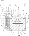
- Fig. 3 is a sectional front view taken along the line A-A of the overcurrent trip device 100 shown in Fig. 2 , showing the state before a trip operation of the overcurrent trip device 100
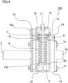
- Fig. 4 is a sectional side view taken along the line B-B of the overcurrent trip device shown in Fig. 2
- Fig. 5 is a sectional plan view taken along the line C-C of the overcurrent trip device shown in Fig. 3
- Fig. 6 is a plan view of a conductor 3 of the overcurrent trip device according to the first embodiment
- Fig. 7 is an illustrated parts breakdown showing a moving core 2 and guide plates 16 of the overcurrent trip device 100 according to the first embodiment.
- the overcurrent trip device 100 is a device which is assembled in a circuit breaker 200 to be described later, wherein when an overcurrent flows through a main circuit (not shown) of the circuit breaker 200, the moving core 2 of the overcurrent trip device 100 moves, causing a latch drive portion 2b provided integral with the moving core 2 to set in motion the opening/closing mechanism of the circuit breaker 200 in the closed state.
- the overcurrent trip device 100 has the conductor 3 which is connected to the main circuit (not shown) of the circuit breaker 200, a stationary core 1 which is formed so as to enclose the conductor 3 along a magnetic field generated around the conductor 3 by energizing the conductor 3 and one portion of which is opened so as to cut the magnetic field diagonally, and the moving core 2 which, being disposed in the opened position of the stationary core 1 with a magnetic gap 4 interposed between the moving core and the stationary core 1, is disposed so as to be movable in a direction in which the magnetic gap 4 decreases with an electromagnetic force of when an overcurrent flows through the conductor 3, that is, in the direction opposite the conductor 3 (in the upward direction in Fig. 3 ) so that the magnetic gap 4 decreases.
- the conductor 3 is made of, for example, copper, and the stationary core 1 and the moving core 2 are made of, for example, a ferromagnet.
- the guide plates 16 for causing the moving core 2 to slide thereon and thereby regulating the range of movement of the moving core are provided one on each of a front and a back surface of the stationary core 1 in an extension direction 20a of the conductor 3.
- the guide plates 16 are provided to guide the up/down movement of the moving core 2.
- opposed coaxial holes 18a and 18b are provided one in each of the guide plates 16 on the respective outer sides of the stationary core 1, and a rotating shaft 6 is provided so as to fit in the opposed holes 18a and 18b which are the portions related thereto.
- a lever 5 which moves rotationally around the rotating shaft 6, one end portion of which is connected to the latch drive portion 2b of the moving core 2 via a moving core pin 2a, and the other end of which is connected to a spring seat 7 via a spring seat pin 7a, is provided between the guide plates 16.
- the spring seat 7 is provided so as to come into close contact with a spring 8.
- the spring seat 7 has the function of serving as the seat of the spring 8 and applying the load force of the spring 8 to the lever 5.
- the load force of the spring 8 is the stress applied by a load, such as the load of the spring 8, which causes deflection.
- the load force applied to the lever 5 is converted to the direction of rotation around the rotating shaft 6 and applied to the moving core 2 in the direction in which the magnetic gap 4 increases.
- a lever cover 15 including an opening through which the latch drive portion 2b of the moving core 2 passes is provided above the lever 5 and fixed to a spring guide 10.
- a compression spring is used as the spring 8, but the spring 8 not being limited specifically to a compression spring, another spring, such as a torsional spring, may be used.
- a stationary core cover 14 is provided so as to cover the outer periphery of the stationary core 1.
- the guide plates 16, the lever 5, the lever cover 15, and the stationary core cover 14 are made of a material, such as austenitic stainless, brass, or aluminum, which is not a ferromagnet.
- the spring guide 10 is fixed to the guide plates 16, via tubes 17, by spring guide rivets 10a.
- the tubes 17 may be omitted.
- the stationary core 1 is disposed in tight abutment with the conductor 3. That is, the conductor 3 is provided fitted in the stationary core 1, and the position of the stationary core 1 in a perpendicular direction 20b to the extension direction 20a of the conductor 3 is determined by the conductor 3. Also, the structure is such that the moving core 2 receives the load force of the spring 8 in the direction in which the magnetic gap 4 increases, and this is supported by the conductor 3, thus fixing the moving core 2.
- the role of a component which determines the position of the stationary core 1 is played by the conductor 3.
- the role of a component which defines the dimensions of the magnetic gap 4 of the moving core 2 is played by the conductor 3, and no other component is provided separately.
- the moving core 2 is supported by the conductor 3.
- an electromagnet configured of the conductor 3, stationary core 1, and moving core 2 of the overcurrent trip device 100 has no space that does not contribute to an electromagnetic force, so that the electromagnet can obtain a greater electromagnetic force compared with in the structure which includes a gap between a conductor and a stationary core and a component with which to fix a moving core as in a heretofore known electromagnet. That is, in order to obtain an arbitrary electromagnetic force, a reduction in dimensional outline size and in weight is carried out by the structure of the overcurrent trip device 100.
- the overcurrent trip device 100 includes outside the stationary core 1 a stage 9 and a spring adjusting bolt 11 in addition to the spring 8.
- the stage 9 being in contact with the spring 8, a threaded portion provided on the spring adjusting bolt 11 mates in a threaded hole provided passing through the center of the stage 9.
- a side surface 9b of the stage 9 is opposite the wall surface of the spring guide 10 inside the spring guide 10 shown in Fig. 4 , thus suppressing the rotation of the stage 9 around the axis of the threaded hole.
- the spring adjusting bolt 11 By causing the spring adjusting bolt 11 to rotate, the stage 9 moves in an axial direction of the threaded hole along the wall surface of the spring guide 10.
- the movement of the stage 9 allows expansion/contraction of the spring 8, thus changing the load force of the spring 8.
- the moving core 2 is urged by the spring 8 in the direction in which the magnetic gap 4 between the moving core and the stationary core 1 increases, and the movement of the stage 9 changes the strength of urging the moving core 2.
- the strength of urging the moving core 2 determines the operating current value of the overcurrent trip device 100, and it is possible, by making this adjustable, to set a plurality of current scale values.
- the initial load of the spring 8 is set to be equal to the electromagnetic drive force at the operating current value of the overcurrent trip device 100.
- a nut 12 is fixed to the spring guide 10 using the threaded portion of the spring adjusting bolt 11, and thereby the spring adjusting bolt 11 is provided so as not to rotate, while the position of the stage 9 is fixed, and thereby the spring 8 is provided so as to be constant in spring load.
- the spring guide 10 is provided surrounding the spring 8 and the side surface 9b of the stage 9.
- the spring guide 10 suppresses deflection of the spring 8 other than the direction of movement of the stage 9 and suppresses rotation of the stage 9.
- the spring guide 10 includes on the outer side thereof a scale 13.
- the scale 13 is thus provided and a protuberant scale indication portion 9a is provided on the stage 9, and thereby the position of the stage 9 is quantitatively grasped from the positional relationship between the protuberant scale indication portion 9a and the scale 13.
- the correlation between the position of the stage 9 and a current scale value can be recorded in advance, and thus it is possible to make a change to the current scale values based on the recorded current scale value without bringing the overcurrent trip device 100 into operation by causing a current to flow through the conductor 3.
- a hole 7b is provided in the center of the spring seat 7, providing the structure in which a cylindrical portion (a non-threaded, smooth-surfaced portion) of the spring adjusting bolt 11 is fitted in the hole 7b, and the hole 7b and the cylindrical portion of the spring adjusting bolt 11 slide when carrying out a trip operation.
- the upper and lower ends of the spring adjusting bolt 11 fit in the spring guide 10. Owing to the same structure, the movement of the spring seat 7 when carrying out the trip operation is restricted to the axial direction by the spring adjusting bolt 11, so that the movement in the direction of rotation centering on the spring seat pin 7a of the spring seat 7 is suppressed before and after the operation. That is, a change in the load force of the spring 8 which transfers to the moving core 2 can be prevented before and after the operation of the overcurrent trip device 100, and it is possible to suppress variation in the operating current value.
- the operating current value of a heretofore known overcurrent trip device is set to an arbitrary value before the overcurrent trip device is assembled in an electrical circuit, but when the operating current value changes after the device is assembled in the electrical circuit, there is concern that breakage of the electrical circuit occurs due to false opening wherein a trip operation is carried out in the state in which an overcurrent is less than a set current value or due to the fact that a circuit breaker is not opened even though the overcurrent exceeds the set current value and that current interruption is not performed against the overcurrent.
- the overcurrent trip device is configured of an electromagnet, and the operating current value is configured of a magnetic flux generated from a main circuit, a magnetic gap of the electromagnet, and a spring load applied by a return spring.
- the hole 7b is provided in the center of the spring seat 7 which is the seat of the spring 8, and the smooth-surfaced cylindrical portion of the spring adjusting bolt 11 with which to adjust the load of the spring 8 is fitted in the hole 7b, wherein the hole 7b and the cylindrical portion of the spring adjusting bolt 11 slide when carrying out a trip operation, and thereby the position of the spring seat 7 before and after the trip operation is set to the axial direction by the cylindrical portion of the spring adjusting bolt 11. Therefore, a change in the load force of the spring 8 which transfers to the moving core 2 can be prevented before and after the operation of the overcurrent trip device 100, and it is possible to suppress variation in the operating current value and as a result possible to stabilize the operating current value.
- the stationary core 1 is configured of a laminated core and includes laminated magnetic steel plates 1b.
- the stationary core 1 is desirably configured of a laminated core for the purpose of suppressing an eddy current, but, not being limited to being of a laminated configuration, may be configured of a block of ferromagnet, such as an iron metal.
- Four stationary core bolts 1a each pass through the laminated magnetic steel plates 1b, the guide plates 16, a conductor front portion 3a, and the stationary core cover 14 in the direction of lamination, fixing these components together.
- the number of the stationary core bolts 1a is not limited to this number as long as it is the number which can fix the above-described components.
- the conductor 3 of the overcurrent trip device 100 being provided in the structure formed of the conductor 3 provided in the position passing through the stationary core 1 and of the conductor front portion 3a provided on the front in the lamination direction of the stationary core 1, is connected to a conductor of the circuit breaker 200 or of the electrical circuit through conductor connection holes 3b.
- the number of the conductor connection holes 3b is provided changed in accord with the shape of a conductor to be connected.
- the conductor 3 and the conductor front portion 3a may be provided in the form of separate components, as shown in Fig. 6 , and the two components may be provided in combination.
- the conductor 3 is fixed to the stationary core 1 by the stationary core bolts 1a, thereby configuring the conductor 3 and the stationary core 1 as an integral unit.
- a protruding portion 2c is provided on each of both surfaces of the moving core 2 which come into contact with the respective guide plates 16, and a groove portion 16a is provided in a portion, of the guide plate 16 corresponding to the protruding portion 2c, which comes into contact with the protruding portion 2c.
- the protruding portion 2c and the groove portion 16a are provided so as to fit each other, and thereby the range of movement of the moving core 2 when in trip operation is restricted to the longitudinal direction of the protruding portion 2c and of the groove portion 16a.
- Fig. 8 is an illustrated parts breakdown showing a modification example of the moving core and guide plates of the overcurrent trip device according to the first embodiment.
- the structure is shown in which the protruding portions 2c are provided on the moving core 2 and the groove portions 16a are provided one in each of the guide plates 16, as shown in Fig. 7 , but as shown in Fig. 8 , groove portions 2d may be provided in the moving core 2 and protruding portions 16b may be provided one on each of the guide plates 16.
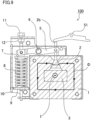
- FIG. 9 is a sectional front view showing the state after a trip operation of the overcurrent trip device 100 according to the first embodiment, and is a sectional front view taken along the line A-A of Fig. 2 .
- a holding latch 51 is linked to the opening/closing mechanism (not shown) included in the circuit breaker 200 and, with one side in contact with the latch drive portion 2b of the moving core 2, is fixed so as to be pivotable.
- the load force is applied to the moving core 2 from the spring 8 and, as shown in Fig. 3 , the moving core 2 is disposed in an initial position (a position before in operation) in which the moving core 2 is opposite the stationary core 1 so as to have the magnetic gap 4.
- the moving core 2 moves from the initial position (position before in operation) to a trip position in which the magnetic gap 4 is reduced to zero, as shown in Fig. 9 .
- the arrows shown in the stationary core 1 and moving core 2 show a magnetic circuit ⁇ , and a fault current I is shown in the conductor 3.
- the latch drive portion 2b causes the holding latch 51 to pivot, and thereby latching is released.
- the opening/closing mechanism of the circuit breaker 200 linked to the holding latch 51 comes in motion, bringing the circuit breaker 200 into the open state.
- the overcurrent trip device 100 of the first embodiment includes the conductor 3 connected to the main circuit of the circuit breaker 200, the stationary core 1 which is formed so as to enclose the conductor 3 and one portion of which is opened, and the moving core 2 which, being disposed in the opened position of the stationary core 1 between the moving core and the stationary core 1 via the magnetic gap 4, is disposed so as to be movable by an electromagnetic force of when an overcurrent flows through the conductor 3, wherein the stationary core 1 is disposed in abutment with the conductor 3, and the moving core 2 is in contact with the conductor 3 when no overcurrent flows through the conductor 3 before in operation.
- the overcurrent trip device 100 of the first embodiment it has the spring 8 with which to apply a return load to the moving core 2 and the lever 5, one end portion of which is linked to the moving core 2 and the other end portion of which is provided outside the stationary core 1. Also, according to the overcurrent trip device 100 of the first embodiment, the spring 8 and the lever 5 are supported on the outer side of the stationary core 1 by the guide plates 16, and the spring 8, the lever 5, and the guide plates 16 are provided integral with the conductor 3 together with the stationary core 1.
- the overcurrent trip device 100 of the first embodiment it is possible to realize a reduction in the size of the overcurrent trip device 100.
- Fig. 10 is a sectional front view of an overcurrent trip device according to a second embodiment.
- components identified by identical signs to those used to describe the overcurrent trip device 100 in the first embodiment indicate identical or corresponding components, and the description thereof is omitted.
- the region shown in section shows the section of the spring adjusting bolt 11 which passes through the center of the axis thereof.
- An overcurrent trip device 100 according to the second embodiment is such that the moving core 2 provided in the overcurrent trip device 100 shown in the first embodiment is different in position and that a connection portion 2e is provided between the latch drive portion 2b and the moving core 2.
- the direction in which the latch drive portion 2b causes the opening/closing mechanism to move is shown by the arrow in Fig. 10 .
- the moving core 2 is provided on the opposite side of the latch drive portion 2b across the conductor 3, so that the connection portion 2e is provided on the way from the moving core 2 to the latch drive portion 2b.
- the direction of movement is the direction toward the conductor 3, so that the latch drive portion 2b is provided in a hook shape, and the rotating shaft 6 of the lever 5 is provided on the outer side of the moving core pin 2a and a spring seat pin (not shown).
- the overcurrent trip device 100 according to the second embodiment is such that the stationary core 1 is disposed in tight abutment with the conductor 3 in the same way as in the first embodiment.
- the conductor 3 is provided fitted in the stationary core 1, and the structure is such that the moving core 2 receives the load force of the spring 8 in the direction in which the magnetic gap 4 increases, and that this is supported by the conductor 3, thus fixing the moving core 2, so that the overcurrent trip device 100 is reduced in dimensional outline size and in weight.
- the position of the moving core 2 is provided on the opposite side of the latch drive portion 2b across the conductor 3, and the direction of causing the opening/closing mechanism to move is different from in the first embodiment, so that it is possible, even when the direction of movement of the opening/closing mechanism is different, to install the overcurrent trip device 100.
- Fig. 11 is a sectional side view showing the outline configuration of a circuit breaker 200 according to a third embodiment.
- the overcurrent trip device 100 shown in the first or second embodiment is assembled in the circuit breaker 200, and the overcurrent trip device 100 sets in motion the opening/closing mechanism of the circuit breaker 200 in the closed state.
- Fig. 11 shows the circuit breaker 200 inserted in a fixing frame 70.
- an upper conductor 53 and a lower conductor 54 are disposed below an arc-extinguishing chamber 52 in which an arc-extinguishing space is formed when a current flows.
- a stationary side main contact 55 is connected to the upper conductor 53.
- the other lower conductor 54 is connected to a moving conductor 57 via a flexible conductor 56, and a moving side main contact 58 is provided in a position, opposite the stationary side main contact 55, of an end portion of the moving conductor 57.
- the moving conductor 57 pivots around a rotating shaft 59, wherein opening is carried out by an opening spring 60, and closing is carried out by an actuator 61.
- the configuration is such that the stationary side main contact 55 and the moving side main contact 58 come into contact with each other, and thereby a current flows between the upper conductor 53 and the lower conductor 54 via the moving conductor 57 and the flexible conductor 56.
- the overcurrent trip device 100 is disposed in the middle of the lower conductor 54.
- the lower conductor 54 is connected to the conductor 3 of the overcurrent trip device 100, and a main circuit current flows therethrough.
- the overcurrent trip device 100 is engaged with a latch 64 by a latch drive link 63.
- the latch drive link 63 shown by the broken line in Fig. 11 corresponds to a portion through which to transfer the movement of the lever 5 of the previously described overcurrent trip device 100 to the holding latch 51, meaning that the latch 64 is driven based on this operation.
- the overcurrent trip device 100 disposed on the lower conductor 54 operates upon detecting an overcurrent, this operation is transferred to the latch 64 by the latch drive link 63, the latch 64 pivots clockwise around a latch shaft 65, releasing the engagement with the moving conductor 57, and the moving conductor 57 pivots clockwise around the rotating shaft 59, thereby carrying out an opening operation.
- the stationary side main contact 55 and the moving side main contact 58 are housed inside the arc-extinguishing chamber 52.
- a stationary side arcing contact 66 and a moving side arcing contact 67 are disposed above the stationary side main contact 55 and the moving side contact 58, and an arc is generated at a breaking time.
- the configuration is such that in the opening operation, the stationary side arcing contact 66 and the moving side arcing contact 67 separate from one another retardedly after separation between the stationary side main contact 55 and the moving side main contact 58, and thereby an arc is prevented from being generated between the stationary side main contact 55 and the moving side main contact 58, thus protecting the main contact portions by preventing them from eroding away.
- a stationary side arcing horn 68 and a moving side arcing horn 69 are disposed above the the stationary side arcing contact 66 and the moving side arcing contact 67 in order to commutate and lead the generated arc to the upper portion of the arc-extinguishing chamber 52.
- the structure of the circuit breaker 200 described in Fig. 11 shows one example, and the structure of the circuit breaker 200 is not limited to the configuration of Fig. 11 . Any structure other than that of the circuit breaker 200 shown in Fig. 11 may be used as long as the structure is of a configuration such that a current flowing through the main circuit of the circuit breaker 200 is detected by the overcurrent trip device 100, and that the engagement between the moving conductor 57 and the latch 64 is released by the operation of the overcurrent trip device 100, thus opening the circuit breaker 200.
- the circuit breaker 200 includes the arc-extinguishing chamber 52 in which the arc-distinguishing space is formed, the stationary side main contact 55 disposed on the lower side of the arc-distinguishing chamber 52, the moving side main contact 58 disposed so as to be able to contact with and separate from the stationary side main contact 55, and the overcurrent trip device 100 which detects an overcurrent flowing between the stationary side main contact 55 and the moving side main contact 58 and drives the moving side main contact 58 in a trip direction, wherein the overcurrent trip device 100 is the overcurrent trip device described in the first or second embodiment.
- the overcurrent trip device 100 shown in the first or second embodiment is assembled therein, so that it is possible to reduce the space of the circuit breaker 200 in which to install the overcurrent trip device 100, and as a result possible to reduce the size of the circuit breaker 200.
Landscapes
- Physics & Mathematics (AREA)
- Electromagnetism (AREA)
- Breakers (AREA)
- Driving Mechanisms And Operating Circuits Of Arc-Extinguishing High-Tension Switches (AREA)
Abstract
Description
- The present application relates to the field of an overcurrent trip device and a circuit breaker using the same.
- An overcurrent trip device is a device which, being assembled in a circuit breaker, detects an overcurrent generated when an electrical circuit including the circuit breaker causes a short circuit accident or the like, and sets in motion the opening/closing mechanism of the circuit breaker in the closed state, thus bringing the circuit breaker into the open state. The circuit breaker shifts into the open state and, at the same time, carries out interruption of an overcurrent flowing through a main circuit. The overcurrent trip device includes, for example, an electromagnet with which to detect the overcurrent flowing through the main circuit, an output shaft with which to transfer a drive force outputted from the electromagnet to the opening/closing mechanism of the circuit breaker, a return spring with which to stabilize an operating current value (the current value of when an opening operation is started) of the overcurrent trip device, and a scale device with which to change the spring load by operating the amount of deflection of the return spring and thereby adjust the operating current value.
- The operation of the overcurrent trip device is such that when an overcurrent flows through a conductor passing through the center of the electromagnet, the attraction occurring in a moving core of the electromagnet exceeds the load of the return spring, whereby the moving core is attracted upward and, at the same time, an operation rod connected to the moving core moves upward, and a holding latch which transfers a closing load to a main circuit contact of the circuit breaker is separated from the main circuit contact, thereby starting up the opening/closing mechanism which urges the circuit breaker into an opening operation (for example, refer to PTL 1). This operation causes the circuit breaker to shift to the open state.
- PTL 1:
EP2431992A1 - According to the previously described
PTL 1, a gap which does not contribute to the operation of the overcurrent trip device or a stopper which determines the position before movement of the moving core is provided between the conductor and the electromagnet, and also, a rod which transfers the load of the return spring to the moving core passes through the conductor, so that in order to obtain a necessary current-carrying capacity to compensate for the reduction in volume of the conductor, there is a need to increase the external dimensions of the conductor, and for these reasons, there is a problem in that the overcurrent trip device grows in external dimensions. - The present application has been made to solve the above problem, and an object of the present application is to obtain an overcurrent trip device which realizes a reduction in the size of the device and a circuit breaker using the same.
- An overcurrent trip device disclosed in the present application is characterized by including a conductor connected to a main circuit of a circuit breaker; a stationary core which is formed so as to enclose the conductor and one portion of which is opened; and a moving core which, being disposed in the opened position of the stationary core with a magnetic gap interposed between the moving core and the stationary core, is disposed so as to be movable by an electromagnetic force of when an overcurrent flows through the conductor, wherein the stationary core is disposed in abutment with the conductor, and the moving core is in contact with the conductor when no overcurrent flows through the conductor before in operation.
- Also, a circuit breaker disclosed in the present application includes an arc-extinguishing chamber in which an arc-extinguishing space is formed; a stationary side main contact disposed on the lower side of the arc-extinguishing chamber; a moving side main contact disposed so as to be able to contact with and separate from the stationary side main contact; and an overcurrent trip device which detects an overcurrent flowing between the stationary side main contact and the moving side main contact and drives the moving side main contact in a trip direction, wherein the previously mentioned overcurrent trip device uses the above-mentioned overcurrent trip device.
- According to the overcurrent trip device disclosed in the present application and to the circuit breaker using the same, it is possible to obtain the overcurrent trip device which can realize a reduction in the size of the device and the circuit breaker using the same.
-
- [
Fig. 1] Fig. 1 is a perspective view of an overcurrent trip device according to a first embodiment. - [
Fig. 2] Fig. 2 is a plan view of the overcurrent trip device according to the first embodiment. - [
Fig. 3] Fig. 3 is a sectional front view taken along the line A-A of the overcurrent trip device shown inFig. 2 . - [
Fig. 4] Fig. 4 is a sectional side view taken along the line B-B of the overcurrent trip device shown inFig. 2 . - [
Fig. 5] Fig. 5 is a sectional plan view taken along the line C-C of the overcurrent trip device shown inFig. 3 . - [
Fig. 6] Fig. 6 is a plan view of a conductor of the overcurrent trip device according to the first embodiment. - [
Fig. 7] Fig. 7 is an illustrated parts breakdown showing a moving core and guide plates of the overcurrent trip device according to the first embodiment. - [
Fig. 8] Fig. 8 is an illustrated parts breakdown showing a modification example of the moving core and guide plates of the overcurrent trip device according to the first embodiment. - [
Fig. 9] Fig. 9 is a sectional front view showing the state after a trip operation of the overcurrent trip device according to the first embodiment. - [
Fig. 10] Fig. 10 is a sectional front view of an overcurrent trip device according to a second embodiment. - [
Fig. 11] Fig. 11 is a sectional side view showing the outline configuration of a circuit breaker according to a third embodiment. - Hereinafter, a description will be given, based on the drawings, of an
overcurrent trip device 100 according to a first embodiment. - In the individual drawings, identical signs indicate identical or equivalent components.
-
Fig. 1 is a perspective view of theovercurrent trip device 100 according to the first embodiment, andFig. 2 is a plan view of theovercurrent trip device 100 according to the first embodiment. Also,Fig. 3 is a sectional front view taken along the line A-A of theovercurrent trip device 100 shown inFig. 2 , showing the state before a trip operation of theovercurrent trip device 100.Fig. 4 is a sectional side view taken along the line B-B of the overcurrent trip device shown inFig. 2 , andFig. 5 is a sectional plan view taken along the line C-C of the overcurrent trip device shown inFig. 3 . Also,Fig. 6 is a plan view of aconductor 3 of the overcurrent trip device according to the first embodiment, andFig. 7 is an illustrated parts breakdown showing a movingcore 2 andguide plates 16 of theovercurrent trip device 100 according to the first embodiment. - The
overcurrent trip device 100 according to the first embodiment is a device which is assembled in acircuit breaker 200 to be described later, wherein when an overcurrent flows through a main circuit (not shown) of thecircuit breaker 200, the movingcore 2 of theovercurrent trip device 100 moves, causing alatch drive portion 2b provided integral with the movingcore 2 to set in motion the opening/closing mechanism of thecircuit breaker 200 in the closed state. - Hereinafter, a description will be given, referring to
Figs. 1 to 7 , of the configuration of theovercurrent trip device 100. - The
overcurrent trip device 100 has theconductor 3 which is connected to the main circuit (not shown) of thecircuit breaker 200, astationary core 1 which is formed so as to enclose theconductor 3 along a magnetic field generated around theconductor 3 by energizing theconductor 3 and one portion of which is opened so as to cut the magnetic field diagonally, and the movingcore 2 which, being disposed in the opened position of thestationary core 1 with amagnetic gap 4 interposed between the moving core and thestationary core 1, is disposed so as to be movable in a direction in which themagnetic gap 4 decreases with an electromagnetic force of when an overcurrent flows through theconductor 3, that is, in the direction opposite the conductor 3 (in the upward direction inFig. 3 ) so that themagnetic gap 4 decreases. - The
conductor 3 is made of, for example, copper, and thestationary core 1 and the movingcore 2 are made of, for example, a ferromagnet. - The
guide plates 16 for causing the movingcore 2 to slide thereon and thereby regulating the range of movement of the moving core are provided one on each of a front and a back surface of thestationary core 1 in anextension direction 20a of theconductor 3. Theguide plates 16 are provided to guide the up/down movement of the movingcore 2. As shown inFig. 7 , opposedcoaxial holes guide plates 16 on the respective outer sides of thestationary core 1, and a rotatingshaft 6 is provided so as to fit in theopposed holes - A
lever 5, which moves rotationally around the rotatingshaft 6, one end portion of which is connected to thelatch drive portion 2b of the movingcore 2 via a movingcore pin 2a, and the other end of which is connected to aspring seat 7 via aspring seat pin 7a, is provided between theguide plates 16. - The
spring seat 7 is provided so as to come into close contact with aspring 8. Thespring seat 7 has the function of serving as the seat of thespring 8 and applying the load force of thespring 8 to thelever 5. The load force of thespring 8 is the stress applied by a load, such as the load of thespring 8, which causes deflection. The load force applied to thelever 5 is converted to the direction of rotation around therotating shaft 6 and applied to the movingcore 2 in the direction in which themagnetic gap 4 increases. Alever cover 15 including an opening through which thelatch drive portion 2b of the movingcore 2 passes is provided above thelever 5 and fixed to aspring guide 10. In the first embodiment, a compression spring is used as thespring 8, but thespring 8 not being limited specifically to a compression spring, another spring, such as a torsional spring, may be used. - Also, in the
overcurrent trip device 100, astationary core cover 14 is provided so as to cover the outer periphery of thestationary core 1. Theguide plates 16, thelever 5, thelever cover 15, and thestationary core cover 14 are made of a material, such as austenitic stainless, brass, or aluminum, which is not a ferromagnet. - Also, as shown in
Fig. 2 , thespring guide 10 is fixed to theguide plates 16, viatubes 17, by spring guide rivets 10a. When thespring guide 10 is in close contact with theguide plates 16, thetubes 17 may be omitted. - As shown in
Fig. 3 , thestationary core 1 is disposed in tight abutment with theconductor 3. That is, theconductor 3 is provided fitted in thestationary core 1, and the position of thestationary core 1 in aperpendicular direction 20b to theextension direction 20a of theconductor 3 is determined by theconductor 3. Also, the structure is such that the movingcore 2 receives the load force of thespring 8 in the direction in which themagnetic gap 4 increases, and this is supported by theconductor 3, thus fixing the movingcore 2. In the same structure, the role of a component which determines the position of thestationary core 1 is played by theconductor 3. Also, the role of a component which defines the dimensions of themagnetic gap 4 of the movingcore 2 is played by theconductor 3, and no other component is provided separately. The movingcore 2 is supported by theconductor 3. - Consequently, an electromagnet configured of the
conductor 3,stationary core 1, and movingcore 2 of theovercurrent trip device 100 has no space that does not contribute to an electromagnetic force, so that the electromagnet can obtain a greater electromagnetic force compared with in the structure which includes a gap between a conductor and a stationary core and a component with which to fix a moving core as in a heretofore known electromagnet. That is, in order to obtain an arbitrary electromagnetic force, a reduction in dimensional outline size and in weight is carried out by the structure of theovercurrent trip device 100. - The
overcurrent trip device 100 includes outside thestationary core 1 astage 9 and a spring adjustingbolt 11 in addition to thespring 8. Thestage 9 being in contact with thespring 8, a threaded portion provided on thespring adjusting bolt 11 mates in a threaded hole provided passing through the center of thestage 9. Aside surface 9b of thestage 9 is opposite the wall surface of thespring guide 10 inside thespring guide 10 shown inFig. 4 , thus suppressing the rotation of thestage 9 around the axis of the threaded hole. By causing thespring adjusting bolt 11 to rotate, thestage 9 moves in an axial direction of the threaded hole along the wall surface of thespring guide 10. - The movement of the
stage 9 allows expansion/contraction of thespring 8, thus changing the load force of thespring 8. The movingcore 2 is urged by thespring 8 in the direction in which themagnetic gap 4 between the moving core and thestationary core 1 increases, and the movement of thestage 9 changes the strength of urging the movingcore 2. The strength of urging the movingcore 2 determines the operating current value of theovercurrent trip device 100, and it is possible, by making this adjustable, to set a plurality of current scale values. The initial load of thespring 8 is set to be equal to the electromagnetic drive force at the operating current value of theovercurrent trip device 100. Furthermore, after setting the operating current value, anut 12 is fixed to thespring guide 10 using the threaded portion of thespring adjusting bolt 11, and thereby thespring adjusting bolt 11 is provided so as not to rotate, while the position of thestage 9 is fixed, and thereby thespring 8 is provided so as to be constant in spring load. - The
spring guide 10 is provided surrounding thespring 8 and theside surface 9b of thestage 9. Thespring guide 10 suppresses deflection of thespring 8 other than the direction of movement of thestage 9 and suppresses rotation of thestage 9. Thespring guide 10 includes on the outer side thereof ascale 13. Thescale 13 is thus provided and a protuberantscale indication portion 9a is provided on thestage 9, and thereby the position of thestage 9 is quantitatively grasped from the positional relationship between the protuberantscale indication portion 9a and thescale 13. - By quantitatively grasping the position of the
stage 9, the correlation between the position of thestage 9 and a current scale value can be recorded in advance, and thus it is possible to make a change to the current scale values based on the recorded current scale value without bringing theovercurrent trip device 100 into operation by causing a current to flow through theconductor 3. - As shown in
Fig. 4 , ahole 7b is provided in the center of thespring seat 7, providing the structure in which a cylindrical portion (a non-threaded, smooth-surfaced portion) of thespring adjusting bolt 11 is fitted in thehole 7b, and thehole 7b and the cylindrical portion of thespring adjusting bolt 11 slide when carrying out a trip operation. Also, the upper and lower ends of thespring adjusting bolt 11 fit in thespring guide 10. Owing to the same structure, the movement of thespring seat 7 when carrying out the trip operation is restricted to the axial direction by thespring adjusting bolt 11, so that the movement in the direction of rotation centering on thespring seat pin 7a of thespring seat 7 is suppressed before and after the operation. That is, a change in the load force of thespring 8 which transfers to the movingcore 2 can be prevented before and after the operation of theovercurrent trip device 100, and it is possible to suppress variation in the operating current value. - The operating current value of a heretofore known overcurrent trip device is set to an arbitrary value before the overcurrent trip device is assembled in an electrical circuit, but when the operating current value changes after the device is assembled in the electrical circuit, there is concern that breakage of the electrical circuit occurs due to false opening wherein a trip operation is carried out in the state in which an overcurrent is less than a set current value or due to the fact that a circuit breaker is not opened even though the overcurrent exceeds the set current value and that current interruption is not performed against the overcurrent. The overcurrent trip device is configured of an electromagnet, and the operating current value is configured of a magnetic flux generated from a main circuit, a magnetic gap of the electromagnet, and a spring load applied by a return spring. Consequently, in order to set the operating current value to be stable, there is a need to establish a structure such that the magnetic gap and the spring load do not change before or after the impact of opening/closing the circuit breaker or the operation of the overcurrent trip device. According to the heretofore known overcurrent trip device, however, there is a problem in that the consideration of suppressing a change in the operating current value has not been undertaken and thus variation occurs in the operating current value.
- According to the
overcurrent trip device 100 of the first embodiment, as shown inFig. 4 , thehole 7b is provided in the center of thespring seat 7 which is the seat of thespring 8, and the smooth-surfaced cylindrical portion of thespring adjusting bolt 11 with which to adjust the load of thespring 8 is fitted in thehole 7b, wherein thehole 7b and the cylindrical portion of thespring adjusting bolt 11 slide when carrying out a trip operation, and thereby the position of thespring seat 7 before and after the trip operation is set to the axial direction by the cylindrical portion of thespring adjusting bolt 11. Therefore, a change in the load force of thespring 8 which transfers to the movingcore 2 can be prevented before and after the operation of theovercurrent trip device 100, and it is possible to suppress variation in the operating current value and as a result possible to stabilize the operating current value. - As shown in
Fig. 5 , thestationary core 1 is configured of a laminated core and includes laminatedmagnetic steel plates 1b. Thestationary core 1 is desirably configured of a laminated core for the purpose of suppressing an eddy current, but, not being limited to being of a laminated configuration, may be configured of a block of ferromagnet, such as an iron metal. Fourstationary core bolts 1a each pass through the laminatedmagnetic steel plates 1b, theguide plates 16, aconductor front portion 3a, and thestationary core cover 14 in the direction of lamination, fixing these components together. The number of thestationary core bolts 1a is not limited to this number as long as it is the number which can fix the above-described components. - As shown in
Fig. 6 , theconductor 3 of theovercurrent trip device 100, being provided in the structure formed of theconductor 3 provided in the position passing through thestationary core 1 and of theconductor front portion 3a provided on the front in the lamination direction of thestationary core 1, is connected to a conductor of thecircuit breaker 200 or of the electrical circuit throughconductor connection holes 3b. The number of theconductor connection holes 3b is provided changed in accord with the shape of a conductor to be connected. Theconductor 3 and theconductor front portion 3a may be provided in the form of separate components, as shown inFig. 6 , and the two components may be provided in combination. As shown inFig. 5 , theconductor 3 is fixed to thestationary core 1 by thestationary core bolts 1a, thereby configuring theconductor 3 and thestationary core 1 as an integral unit. - As shown in
Fig. 7 , a protrudingportion 2c is provided on each of both surfaces of the movingcore 2 which come into contact with therespective guide plates 16, and agroove portion 16a is provided in a portion, of theguide plate 16 corresponding to the protrudingportion 2c, which comes into contact with the protrudingportion 2c. The protrudingportion 2c and thegroove portion 16a are provided so as to fit each other, and thereby the range of movement of the movingcore 2 when in trip operation is restricted to the longitudinal direction of the protrudingportion 2c and of thegroove portion 16a. - That is, it is possible to suppress the positional change of the moving
core 2 before and after the impact of opening/closing thecircuit breaker 200 or the operation of theovercurrent trip device 100, and thus possible to suppress variation in the operating current value. -
Fig. 8 is an illustrated parts breakdown showing a modification example of the moving core and guide plates of the overcurrent trip device according to the first embodiment. In the first embodiment, the structure is shown in which the protrudingportions 2c are provided on the movingcore 2 and thegroove portions 16a are provided one in each of theguide plates 16, as shown inFig. 7 , but as shown inFig. 8 ,groove portions 2d may be provided in the movingcore 2 and protrudingportions 16b may be provided one on each of theguide plates 16. - Next, a description will be given of a trip operation of the
overcurrent trip device 100.Fig. 9 is a sectional front view showing the state after a trip operation of theovercurrent trip device 100 according to the first embodiment, and is a sectional front view taken along the line A-A ofFig. 2 . As shown inFig. 9 , a holdinglatch 51 is linked to the opening/closing mechanism (not shown) included in thecircuit breaker 200 and, with one side in contact with thelatch drive portion 2b of the movingcore 2, is fixed so as to be pivotable. Before a trip operation wherein no fault current flows through theconductor 3, the load force is applied to the movingcore 2 from thespring 8 and, as shown inFig. 3 , the movingcore 2 is disposed in an initial position (a position before in operation) in which the movingcore 2 is opposite thestationary core 1 so as to have themagnetic gap 4. - When a fault current flows through the
conductor 3 and an electromagnetic drive force acting on the movingcore 2 is greater than the load force of thespring 8, the movingcore 2 moves from the initial position (position before in operation) to a trip position in which themagnetic gap 4 is reduced to zero, as shown inFig. 9 . InFig. 9 , the arrows shown in thestationary core 1 and movingcore 2 show a magnetic circuit Φ, and a fault current I is shown in theconductor 3. By the movingcore 2 moving, thelatch drive portion 2b causes the holdinglatch 51 to pivot, and thereby latching is released. The opening/closing mechanism of thecircuit breaker 200 linked to the holdinglatch 51 comes in motion, bringing thecircuit breaker 200 into the open state. - As above, according to the
overcurrent trip device 100 of the first embodiment, it includes theconductor 3 connected to the main circuit of thecircuit breaker 200, thestationary core 1 which is formed so as to enclose theconductor 3 and one portion of which is opened, and the movingcore 2 which, being disposed in the opened position of thestationary core 1 between the moving core and thestationary core 1 via themagnetic gap 4, is disposed so as to be movable by an electromagnetic force of when an overcurrent flows through theconductor 3, wherein thestationary core 1 is disposed in abutment with theconductor 3, and the movingcore 2 is in contact with theconductor 3 when no overcurrent flows through theconductor 3 before in operation. - Also, according to the
overcurrent trip device 100 of the first embodiment, it has thespring 8 with which to apply a return load to the movingcore 2 and thelever 5, one end portion of which is linked to the movingcore 2 and the other end portion of which is provided outside thestationary core 1. Also, according to theovercurrent trip device 100 of the first embodiment, thespring 8 and thelever 5 are supported on the outer side of thestationary core 1 by theguide plates 16, and thespring 8, thelever 5, and theguide plates 16 are provided integral with theconductor 3 together with thestationary core 1. - Consequently, according to the
overcurrent trip device 100 of the first embodiment, it is possible to realize a reduction in the size of theovercurrent trip device 100. -
Fig. 10 is a sectional front view of an overcurrent trip device according to a second embodiment. InFig. 10 , components identified by identical signs to those used to describe theovercurrent trip device 100 in the first embodiment indicate identical or corresponding components, and the description thereof is omitted. InFig. 10 , the region shown in section shows the section of thespring adjusting bolt 11 which passes through the center of the axis thereof. Anovercurrent trip device 100 according to the second embodiment is such that the movingcore 2 provided in theovercurrent trip device 100 shown in the first embodiment is different in position and that aconnection portion 2e is provided between thelatch drive portion 2b and the movingcore 2. - The direction in which the
latch drive portion 2b causes the opening/closing mechanism to move is shown by the arrow inFig. 10 . The movingcore 2 is provided on the opposite side of thelatch drive portion 2b across theconductor 3, so that theconnection portion 2e is provided on the way from the movingcore 2 to thelatch drive portion 2b. Also, the direction of movement is the direction toward theconductor 3, so that thelatch drive portion 2b is provided in a hook shape, and therotating shaft 6 of thelever 5 is provided on the outer side of the movingcore pin 2a and a spring seat pin (not shown). Theovercurrent trip device 100 according to the second embodiment is such that thestationary core 1 is disposed in tight abutment with theconductor 3 in the same way as in the first embodiment. That is, theconductor 3 is provided fitted in thestationary core 1, and the structure is such that the movingcore 2 receives the load force of thespring 8 in the direction in which themagnetic gap 4 increases, and that this is supported by theconductor 3, thus fixing the movingcore 2, so that theovercurrent trip device 100 is reduced in dimensional outline size and in weight. - As above, according to the
overcurrent trip device 100 of the second embodiment, the position of the movingcore 2 is provided on the opposite side of thelatch drive portion 2b across theconductor 3, and the direction of causing the opening/closing mechanism to move is different from in the first embodiment, so that it is possible, even when the direction of movement of the opening/closing mechanism is different, to install theovercurrent trip device 100. -
Fig. 11 is a sectional side view showing the outline configuration of acircuit breaker 200 according to a third embodiment. Hereinafter, a description will be given, referring to the drawing, of thecircuit breaker 200 according to the third embodiment. As shown inFig. 11 , theovercurrent trip device 100 shown in the first or second embodiment is assembled in thecircuit breaker 200, and theovercurrent trip device 100 sets in motion the opening/closing mechanism of thecircuit breaker 200 in the closed state.Fig. 11 shows thecircuit breaker 200 inserted in a fixingframe 70. - In the
circuit breaker 200, anupper conductor 53 and alower conductor 54 are disposed below an arc-extinguishingchamber 52 in which an arc-extinguishing space is formed when a current flows. - A stationary side
main contact 55 is connected to theupper conductor 53. The otherlower conductor 54 is connected to a movingconductor 57 via aflexible conductor 56, and a moving sidemain contact 58 is provided in a position, opposite the stationary sidemain contact 55, of an end portion of the movingconductor 57. The movingconductor 57 pivots around a rotatingshaft 59, wherein opening is carried out by anopening spring 60, and closing is carried out by anactuator 61. The configuration is such that the stationary sidemain contact 55 and the moving sidemain contact 58 come into contact with each other, and thereby a current flows between theupper conductor 53 and thelower conductor 54 via the movingconductor 57 and theflexible conductor 56. - The
overcurrent trip device 100 is disposed in the middle of thelower conductor 54. Thelower conductor 54 is connected to theconductor 3 of theovercurrent trip device 100, and a main circuit current flows therethrough. Also, theovercurrent trip device 100 is engaged with alatch 64 by alatch drive link 63. Herein, thelatch drive link 63 shown by the broken line inFig. 11 corresponds to a portion through which to transfer the movement of thelever 5 of the previously describedovercurrent trip device 100 to the holdinglatch 51, meaning that thelatch 64 is driven based on this operation. - Next, a description will be given of the operation when the fault current I flows. When the fault current I flows, the
overcurrent trip device 100 disposed on thelower conductor 54 operates upon detecting an overcurrent, this operation is transferred to thelatch 64 by thelatch drive link 63, thelatch 64 pivots clockwise around alatch shaft 65, releasing the engagement with the movingconductor 57, and the movingconductor 57 pivots clockwise around the rotatingshaft 59, thereby carrying out an opening operation. - The stationary side
main contact 55 and the moving sidemain contact 58 are housed inside the arc-extinguishingchamber 52. A stationaryside arcing contact 66 and a movingside arcing contact 67 are disposed above the stationary sidemain contact 55 and the movingside contact 58, and an arc is generated at a breaking time. - The configuration is such that in the opening operation, the stationary
side arcing contact 66 and the movingside arcing contact 67 separate from one another retardedly after separation between the stationary sidemain contact 55 and the moving sidemain contact 58, and thereby an arc is prevented from being generated between the stationary sidemain contact 55 and the moving sidemain contact 58, thus protecting the main contact portions by preventing them from eroding away. Also, a stationaryside arcing horn 68 and a movingside arcing horn 69 are disposed above the the stationaryside arcing contact 66 and the movingside arcing contact 67 in order to commutate and lead the generated arc to the upper portion of the arc-extinguishingchamber 52. - The structure of the
circuit breaker 200 described inFig. 11 shows one example, and the structure of thecircuit breaker 200 is not limited to the configuration ofFig. 11 . Any structure other than that of thecircuit breaker 200 shown inFig. 11 may be used as long as the structure is of a configuration such that a current flowing through the main circuit of thecircuit breaker 200 is detected by theovercurrent trip device 100, and that the engagement between the movingconductor 57 and thelatch 64 is released by the operation of theovercurrent trip device 100, thus opening thecircuit breaker 200. - As above, the
circuit breaker 200 according to the third embodiment includes the arc-extinguishingchamber 52 in which the arc-distinguishing space is formed, the stationary sidemain contact 55 disposed on the lower side of the arc-distinguishingchamber 52, the moving sidemain contact 58 disposed so as to be able to contact with and separate from the stationary sidemain contact 55, and theovercurrent trip device 100 which detects an overcurrent flowing between the stationary sidemain contact 55 and the moving sidemain contact 58 and drives the moving sidemain contact 58 in a trip direction, wherein theovercurrent trip device 100 is the overcurrent trip device described in the first or second embodiment. - Consequently, according to the
circuit breaker 200 of the third embodiment, theovercurrent trip device 100 shown in the first or second embodiment is assembled therein, so that it is possible to reduce the space of thecircuit breaker 200 in which to install theovercurrent trip device 100, and as a result possible to reduce the size of thecircuit breaker 200. - Although the present application is described above in terms of various exemplary embodiments and implementations, it should be understood that the various features, aspects, and functionality described in one or more of the individual embodiments are not limited in their applicability to the particular embodiment with which they are described, but instead can be applied, alone or in various combinations, to one or more of the embodiments.
- It is therefore understood that numerous modifications which have not been exemplified can be devised without departing from the scope of the present application. For example, at least one of the constituent components may be modified, added, or eliminated. At least one of the constituent components mentioned in at least one of the preferred embodiments may be selected and combined with the constituent components mentioned in another preferred embodiment.
- 1 stationary core, 1a stationary core bolt, 1b magnetic steel plate, 2 moving core, 2a moving core pin, 2b latch drive portion, 2c protruding portion, 2d groove portion, 2e connection portion, 3 conductor, 3a conductor front portion, 3b conductor connection hole, 4 magnetic gap, 5 lever, 6 rotating shaft, 7 spring seat, 7a spring seat pin, 7b hole, 8 spring, 9 stage, 9a scale indication portion, 9b side surface, 10 spring guide, 10a spring guide rivet, 11 spring adjusting bolt, 12 nut, 13 scale, 14 stationary core cover, 15 lever cover, 16 guide plate, 16a groove portion, 16b protruding portion, 17 tube, 18a, 18b opposed holes, 20a extension direction, 20b perpendicular direction, 51 holding latch, 52 arc-distinguishing chamber, 53 upper conductor, 54 lower conductor, 55 stationary side main contact, 56 flexible conductor, 57 moving conductor, 58 moving side main contact, 59 rotating shaft, 60 opening spring, 61 actuator, 63 latch drive link, 64 latch, 65 latch shaft, 66 stationary side arcing contact, 67 moving side arcing contact, 68 stationary side arcing horn, 69 moving side arcing horn, 70 fixing frame, 100 overcurrent trip device, 200 circuit breaker, I fault current, Φ magnetic circuit
Claims (9)
- An overcurrent trip device, characterized by comprising:a conductor connected to a main circuit of a circuit breaker;a stationary core which is formed so as to enclose the conductor and one portion of which is opened; anda moving core which, being disposed in the opened position of the stationary core with a magnetic gap interposed between the moving core and the stationary core, is disposed so as to be movable by an electromagnetic force of when an overcurrent flows through the conductor, whereinthe stationary core is disposed in abutment with the conductor, and the moving core is in contact with the conductor when no overcurrent flows through the conductor before in operation.
- The overcurrent trip device according to claim 1, characterized in that
the moving core is caused to move in the direction opposite the conductor so that the magnetic gap decreases when an overcurrent flows through the conductor. - The overcurrent trip device according to claim 1 or 2, characterized in that
guide plates which guide up/down movement of the moving core are provided one on each of a front and a back surface of the stationary core in the direction in which the conductor extends. - The overcurrent trip device according to claim 3, characterized in thatthe moving core has protruding portions, one on each of a front and a back surface of the moving core in the direction in which the conductor extends, thatthe guide plates each have a groove portion opposite the corresponding protruding portion, and thatthe protruding portions of the moving core are provided so as to fit in the respective groove portions of the guide plates.
- The overcurrent trip device according to any one of claims 1 to 4, characterized by comprising:a spring with which to apply a return load to the moving core; anda lever, one end portion of which is linked to the moving core, and the other end portion of which is linked to the spring provided outside the stationary core.
- The overcurrent trip device according to claim 3 or 4, characterized by comprising:a spring with which to apply a return load to the moving core; anda lever, one end portion of which is linked to the moving core, and the other end portion of which is linked to the spring provided outside the stationary core, whereinthe spring and the lever are supported outside the stationary core by the guide plates, and whereinthe spring, the lever, and the guide plates are provided integral with the conductor together with the stationary core.
- The overcurrent trip device according to claim 5 or 6, characterized in thata rotating shaft is disposed in the lever, andthe lever pivots around the axis of the rotating shaft, transferring the load force of the spring to the moving core.
- The overcurrent trip device according to any one of claims 5 to 7, characterized in thata hole is provided in the center of a spring seat which is the seat of the spring, thata smooth-surfaced cylindrical portion of a spring adjusting bolt with which to adjust the load of the spring is fitted in the hole, and thatthe hole and the cylindrical portion of the spring adjusting bolt slide when carrying out a trip operation, and thereby the position of the spring seat before and after the trip operation is set to an axial direction by the cylindrical portion of the spring adjusting bolt.
- A circuit breaker, characterized by comprising:an arc-extinguishing chamber in which an arc-extinguishing space is formed;a stationary side main contact disposed on the lower side of the arc-extinguishing chamber;a moving side main contact disposed so as to be able to contact with and separate from the stationary side main contact; andan overcurrent trip device which detects an overcurrent flowing between the stationary side main contact and the moving side main contact and drives the moving side main contact in a trip direction, whereinthe overcurrent trip device is the overcurrent trip device according to any one of claims 1 to 8.
Applications Claiming Priority (1)
| Application Number | Priority Date | Filing Date | Title |
|---|---|---|---|
| PCT/JP2020/047083 WO2022130552A1 (en) | 2020-12-17 | 2020-12-17 | Overcurrent trip device, and circuit breaker using same |
Publications (3)
| Publication Number | Publication Date |
|---|---|
| EP4266343A1 true EP4266343A1 (en) | 2023-10-25 |
| EP4266343A4 EP4266343A4 (en) | 2024-03-06 |
| EP4266343B1 EP4266343B1 (en) | 2026-04-15 |
Family
ID=82059220
Family Applications (1)
| Application Number | Title | Priority Date | Filing Date |
|---|---|---|---|
| EP20965940.8A Active EP4266343B1 (en) | 2020-12-17 | 2020-12-17 | Overcurrent trip device, and circuit breaker using same |
Country Status (3)
| Country | Link |
|---|---|
| EP (1) | EP4266343B1 (en) |
| JP (1) | JP7412600B2 (en) |
| WO (1) | WO2022130552A1 (en) |
Cited By (1)
| Publication number | Priority date | Publication date | Assignee | Title |
|---|---|---|---|---|
| EP4567853A1 (en) * | 2023-12-05 | 2025-06-11 | ALSTOM Holdings | High speed circuit breaker comprising a movable magnetic shim in an air gap of a magnetic circuit |
Family Cites Families (7)
| Publication number | Priority date | Publication date | Assignee | Title |
|---|---|---|---|---|
| FR2501929A1 (en) * | 1981-03-10 | 1982-09-17 | Merlin Gerin | LOW VOLTAGE CIRCUIT BREAKER AND METHOD FOR MANUFACTURING A CURRENT SENSOR |
| JPS60119705A (en) * | 1983-12-01 | 1985-06-27 | Mitsubishi Mining & Cement Co Ltd | Electromagnetic tripping device |
| JPH0431724Y2 (en) * | 1987-10-07 | 1992-07-30 | ||
| JP3311917B2 (en) * | 1996-01-22 | 2002-08-05 | 寺崎電気産業株式会社 | Draw-out type circuit breaker |
| DE29723307U1 (en) * | 1997-04-11 | 1998-08-06 | AEG Niederspannungstechnik GmbH & Co KG, 24534 Neumünster | Fast overcurrent release for DC high-speed switches |
| US10453638B2 (en) * | 2015-06-19 | 2019-10-22 | Mitsubishi Electric Corporation | Overcurrent tripping device and circuit breaker employing same |
| JP7109664B2 (en) * | 2019-05-16 | 2022-07-29 | 三菱電機株式会社 | Overcurrent trip device and circuit breaker using the same |
-
2020
- 2020-12-17 WO PCT/JP2020/047083 patent/WO2022130552A1/en not_active Ceased
- 2020-12-17 JP JP2022569411A patent/JP7412600B2/en active Active
- 2020-12-17 EP EP20965940.8A patent/EP4266343B1/en active Active
Cited By (1)
| Publication number | Priority date | Publication date | Assignee | Title |
|---|---|---|---|---|
| EP4567853A1 (en) * | 2023-12-05 | 2025-06-11 | ALSTOM Holdings | High speed circuit breaker comprising a movable magnetic shim in an air gap of a magnetic circuit |
Also Published As
| Publication number | Publication date |
|---|---|
| EP4266343A4 (en) | 2024-03-06 |
| JPWO2022130552A1 (en) | 2022-06-23 |
| JP7412600B2 (en) | 2024-01-12 |
| WO2022130552A1 (en) | 2022-06-23 |
| EP4266343B1 (en) | 2026-04-15 |
Similar Documents
| Publication | Publication Date | Title |
|---|---|---|
| US8373523B2 (en) | Electromagnetic trip device | |
| EP1756845B1 (en) | Electrical contactor | |
| US5175403A (en) | Recloser means for reclosing interrupted high voltage electric circuit means | |
| JP3805377B2 (en) | Electric switch | |
| EP3051567B1 (en) | Adjustable electromagnetic release | |
| JPH0463489B2 (en) | ||
| US9269513B2 (en) | Contactor arrangement for use in dielectric liquid | |
| JP6072065B2 (en) | TRIP MECHANISM AND ELECTRICAL SWITCHING EQUIPMENT INCLUDING TRIP MEMBER PRESSED BY PRESSURE RESULTING FROM AN ARC IN AN ARC Chamber | |
| JP7399276B2 (en) | trip device | |
| EP4266343B1 (en) | Overcurrent trip device, and circuit breaker using same | |
| JP7109664B2 (en) | Overcurrent trip device and circuit breaker using the same | |
| US5023583A (en) | Circuit breaker contact operating structure | |
| KR100311344B1 (en) | Electrical circuit breakers | |
| HK40096955A (en) | Overcurrent trip device, and circuit breaker using same | |
| US7978036B2 (en) | Method and device for the secure operation of a switching device | |
| EP2801995A1 (en) | Circuit breaker | |
| EP3981019B1 (en) | Electrical contact system for a switching device | |
| JP7540415B2 (en) | Circuit Breakers | |
| HK40067800A (en) | Overcurrent tripping device, and circuit breaker in which overcurrent tripping device is used | |
| HK40067800B (en) | Overcurrent tripping device, and circuit breaker in which overcurrent tripping device is used | |
| KR20250048656A (en) | Dynamically adjustable magnetic yoke assembly for electromechanical switching devices | |
| EP3059749B1 (en) | Circuit breaker including current path geometries that increase contact self-popping level | |
| KR200440694Y1 (en) | Forward seating device of circuit breaker | |
| HK1019508B (en) | Electrical circuit breakers | |
| GB2149216A (en) | Electric circuit breakers |
Legal Events
| Date | Code | Title | Description |
|---|---|---|---|
| STAA | Information on the status of an ep patent application or granted ep patent |
Free format text: STATUS: THE INTERNATIONAL PUBLICATION HAS BEEN MADE |
|
| PUAI | Public reference made under article 153(3) epc to a published international application that has entered the european phase |
Free format text: ORIGINAL CODE: 0009012 |
|
| STAA | Information on the status of an ep patent application or granted ep patent |
Free format text: STATUS: REQUEST FOR EXAMINATION WAS MADE |
|
| 17P | Request for examination filed |
Effective date: 20230116 |
|
| AK | Designated contracting states |
Kind code of ref document: A1 Designated state(s): AL AT BE BG CH CY CZ DE DK EE ES FI FR GB GR HR HU IE IS IT LI LT LU LV MC MK MT NL NO PL PT RO RS SE SI SK SM TR |
|
| REG | Reference to a national code |
Ref country code: HK Ref legal event code: DE Ref document number: 40096955 Country of ref document: HK |
|
| A4 | Supplementary search report drawn up and despatched |
Effective date: 20240201 |
|
| RIC1 | Information provided on ipc code assigned before grant |
Ipc: H01H 71/24 20060101ALI20240126BHEP Ipc: H01H 73/36 20060101AFI20240126BHEP |
|
| DAV | Request for validation of the european patent (deleted) | ||
| DAX | Request for extension of the european patent (deleted) | ||
| GRAP | Despatch of communication of intention to grant a patent |
Free format text: ORIGINAL CODE: EPIDOSNIGR1 |
|
| STAA | Information on the status of an ep patent application or granted ep patent |
Free format text: STATUS: GRANT OF PATENT IS INTENDED |
|
| INTG | Intention to grant announced |
Effective date: 20251112 |
|
| GRAS | Grant fee paid |
Free format text: ORIGINAL CODE: EPIDOSNIGR3 |
|
| GRAA | (expected) grant |
Free format text: ORIGINAL CODE: 0009210 |
|
| STAA | Information on the status of an ep patent application or granted ep patent |
Free format text: STATUS: THE PATENT HAS BEEN GRANTED |
|
| AK | Designated contracting states |
Kind code of ref document: B1 Designated state(s): AL AT BE BG CH CY CZ DE DK EE ES FI FR GB GR HR HU IE IS IT LI LT LU LV MC MK MT NL NO PL PT RO RS SE SI SK SM TR |
|
| REG | Reference to a national code |
Ref country code: CH Ref legal event code: F10 Free format text: ST27 STATUS EVENT CODE: U-0-0-F10-F00 (AS PROVIDED BY THE NATIONAL OFFICE) Effective date: 20260415 |
|
| REG | Reference to a national code |
Ref country code: CH Ref legal event code: R17 Free format text: ST27 STATUS EVENT CODE: U-0-0-R10-R17 (AS PROVIDED BY THE NATIONAL OFFICE) Effective date: 20260416 |