EP4266286A1 - Vehicle motion control device and vehicle motion control method - Google Patents
Vehicle motion control device and vehicle motion control method Download PDFInfo
- Publication number
- EP4266286A1 EP4266286A1 EP21906206.4A EP21906206A EP4266286A1 EP 4266286 A1 EP4266286 A1 EP 4266286A1 EP 21906206 A EP21906206 A EP 21906206A EP 4266286 A1 EP4266286 A1 EP 4266286A1
- Authority
- EP
- European Patent Office
- Prior art keywords
- vehicle
- acceleration
- traveling
- motion control
- control device
- Prior art date
- Legal status (The legal status is an assumption and is not a legal conclusion. Google has not performed a legal analysis and makes no representation as to the accuracy of the status listed.)
- Granted
Links
Images



Classifications
-
- B—PERFORMING OPERATIONS; TRANSPORTING
- B60—VEHICLES IN GENERAL
- B60W—CONJOINT CONTROL OF VEHICLE SUB-UNITS OF DIFFERENT TYPE OR DIFFERENT FUNCTION; CONTROL SYSTEMS SPECIALLY ADAPTED FOR HYBRID VEHICLES; ROAD VEHICLE DRIVE CONTROL SYSTEMS FOR PURPOSES NOT RELATED TO THE CONTROL OF A PARTICULAR SUB-UNIT
- B60W30/00—Purposes of road vehicle drive control systems not related to the control of a particular sub-unit, e.g. of systems using conjoint control of vehicle sub-units
- B60W30/18—Propelling the vehicle
- B60W30/182—Selecting between different operative modes, e.g. comfort and performance modes
-
- B—PERFORMING OPERATIONS; TRANSPORTING
- B60—VEHICLES IN GENERAL
- B60W—CONJOINT CONTROL OF VEHICLE SUB-UNITS OF DIFFERENT TYPE OR DIFFERENT FUNCTION; CONTROL SYSTEMS SPECIALLY ADAPTED FOR HYBRID VEHICLES; ROAD VEHICLE DRIVE CONTROL SYSTEMS FOR PURPOSES NOT RELATED TO THE CONTROL OF A PARTICULAR SUB-UNIT
- B60W40/00—Estimation or calculation of non-directly measurable driving parameters for road vehicle drive control systems not related to the control of a particular sub unit, e.g. by using mathematical models
- B60W40/02—Estimation or calculation of non-directly measurable driving parameters for road vehicle drive control systems not related to the control of a particular sub unit, e.g. by using mathematical models related to ambient conditions
- B60W40/06—Road conditions
- B60W40/072—Curvature of the road
-
- B—PERFORMING OPERATIONS; TRANSPORTING
- B60—VEHICLES IN GENERAL
- B60W—CONJOINT CONTROL OF VEHICLE SUB-UNITS OF DIFFERENT TYPE OR DIFFERENT FUNCTION; CONTROL SYSTEMS SPECIALLY ADAPTED FOR HYBRID VEHICLES; ROAD VEHICLE DRIVE CONTROL SYSTEMS FOR PURPOSES NOT RELATED TO THE CONTROL OF A PARTICULAR SUB-UNIT
- B60W10/00—Conjoint control of vehicle sub-units of different type or different function
- B60W10/04—Conjoint control of vehicle sub-units of different type or different function including control of propulsion units
-
- B—PERFORMING OPERATIONS; TRANSPORTING
- B60—VEHICLES IN GENERAL
- B60W—CONJOINT CONTROL OF VEHICLE SUB-UNITS OF DIFFERENT TYPE OR DIFFERENT FUNCTION; CONTROL SYSTEMS SPECIALLY ADAPTED FOR HYBRID VEHICLES; ROAD VEHICLE DRIVE CONTROL SYSTEMS FOR PURPOSES NOT RELATED TO THE CONTROL OF A PARTICULAR SUB-UNIT
- B60W10/00—Conjoint control of vehicle sub-units of different type or different function
- B60W10/18—Conjoint control of vehicle sub-units of different type or different function including control of braking systems
-
- B—PERFORMING OPERATIONS; TRANSPORTING
- B60—VEHICLES IN GENERAL
- B60W—CONJOINT CONTROL OF VEHICLE SUB-UNITS OF DIFFERENT TYPE OR DIFFERENT FUNCTION; CONTROL SYSTEMS SPECIALLY ADAPTED FOR HYBRID VEHICLES; ROAD VEHICLE DRIVE CONTROL SYSTEMS FOR PURPOSES NOT RELATED TO THE CONTROL OF A PARTICULAR SUB-UNIT
- B60W10/00—Conjoint control of vehicle sub-units of different type or different function
- B60W10/20—Conjoint control of vehicle sub-units of different type or different function including control of steering systems
-
- B—PERFORMING OPERATIONS; TRANSPORTING
- B60—VEHICLES IN GENERAL
- B60W—CONJOINT CONTROL OF VEHICLE SUB-UNITS OF DIFFERENT TYPE OR DIFFERENT FUNCTION; CONTROL SYSTEMS SPECIALLY ADAPTED FOR HYBRID VEHICLES; ROAD VEHICLE DRIVE CONTROL SYSTEMS FOR PURPOSES NOT RELATED TO THE CONTROL OF A PARTICULAR SUB-UNIT
- B60W30/00—Purposes of road vehicle drive control systems not related to the control of a particular sub-unit, e.g. of systems using conjoint control of vehicle sub-units
- B60W30/02—Control of vehicle driving stability
-
- B—PERFORMING OPERATIONS; TRANSPORTING
- B60—VEHICLES IN GENERAL
- B60W—CONJOINT CONTROL OF VEHICLE SUB-UNITS OF DIFFERENT TYPE OR DIFFERENT FUNCTION; CONTROL SYSTEMS SPECIALLY ADAPTED FOR HYBRID VEHICLES; ROAD VEHICLE DRIVE CONTROL SYSTEMS FOR PURPOSES NOT RELATED TO THE CONTROL OF A PARTICULAR SUB-UNIT
- B60W30/00—Purposes of road vehicle drive control systems not related to the control of a particular sub-unit, e.g. of systems using conjoint control of vehicle sub-units
- B60W30/14—Adaptive cruise control
- B60W30/143—Speed control
-
- B—PERFORMING OPERATIONS; TRANSPORTING
- B60—VEHICLES IN GENERAL
- B60W—CONJOINT CONTROL OF VEHICLE SUB-UNITS OF DIFFERENT TYPE OR DIFFERENT FUNCTION; CONTROL SYSTEMS SPECIALLY ADAPTED FOR HYBRID VEHICLES; ROAD VEHICLE DRIVE CONTROL SYSTEMS FOR PURPOSES NOT RELATED TO THE CONTROL OF A PARTICULAR SUB-UNIT
- B60W30/00—Purposes of road vehicle drive control systems not related to the control of a particular sub-unit, e.g. of systems using conjoint control of vehicle sub-units
- B60W30/18—Propelling the vehicle
- B60W30/18009—Propelling the vehicle related to particular drive situations
- B60W30/18145—Cornering
-
- B—PERFORMING OPERATIONS; TRANSPORTING
- B60—VEHICLES IN GENERAL
- B60W—CONJOINT CONTROL OF VEHICLE SUB-UNITS OF DIFFERENT TYPE OR DIFFERENT FUNCTION; CONTROL SYSTEMS SPECIALLY ADAPTED FOR HYBRID VEHICLES; ROAD VEHICLE DRIVE CONTROL SYSTEMS FOR PURPOSES NOT RELATED TO THE CONTROL OF A PARTICULAR SUB-UNIT
- B60W30/00—Purposes of road vehicle drive control systems not related to the control of a particular sub-unit, e.g. of systems using conjoint control of vehicle sub-units
- B60W30/18—Propelling the vehicle
- B60W30/18009—Propelling the vehicle related to particular drive situations
- B60W30/18163—Lane change; Overtaking manoeuvres
-
- B—PERFORMING OPERATIONS; TRANSPORTING
- B60—VEHICLES IN GENERAL
- B60W—CONJOINT CONTROL OF VEHICLE SUB-UNITS OF DIFFERENT TYPE OR DIFFERENT FUNCTION; CONTROL SYSTEMS SPECIALLY ADAPTED FOR HYBRID VEHICLES; ROAD VEHICLE DRIVE CONTROL SYSTEMS FOR PURPOSES NOT RELATED TO THE CONTROL OF A PARTICULAR SUB-UNIT
- B60W40/00—Estimation or calculation of non-directly measurable driving parameters for road vehicle drive control systems not related to the control of a particular sub unit, e.g. by using mathematical models
- B60W40/10—Estimation or calculation of non-directly measurable driving parameters for road vehicle drive control systems not related to the control of a particular sub unit, e.g. by using mathematical models related to vehicle motion
- B60W40/107—Longitudinal acceleration
-
- B—PERFORMING OPERATIONS; TRANSPORTING
- B60—VEHICLES IN GENERAL
- B60W—CONJOINT CONTROL OF VEHICLE SUB-UNITS OF DIFFERENT TYPE OR DIFFERENT FUNCTION; CONTROL SYSTEMS SPECIALLY ADAPTED FOR HYBRID VEHICLES; ROAD VEHICLE DRIVE CONTROL SYSTEMS FOR PURPOSES NOT RELATED TO THE CONTROL OF A PARTICULAR SUB-UNIT
- B60W40/00—Estimation or calculation of non-directly measurable driving parameters for road vehicle drive control systems not related to the control of a particular sub unit, e.g. by using mathematical models
- B60W40/10—Estimation or calculation of non-directly measurable driving parameters for road vehicle drive control systems not related to the control of a particular sub unit, e.g. by using mathematical models related to vehicle motion
- B60W40/109—Lateral acceleration
-
- B—PERFORMING OPERATIONS; TRANSPORTING
- B60—VEHICLES IN GENERAL
- B60W—CONJOINT CONTROL OF VEHICLE SUB-UNITS OF DIFFERENT TYPE OR DIFFERENT FUNCTION; CONTROL SYSTEMS SPECIALLY ADAPTED FOR HYBRID VEHICLES; ROAD VEHICLE DRIVE CONTROL SYSTEMS FOR PURPOSES NOT RELATED TO THE CONTROL OF A PARTICULAR SUB-UNIT
- B60W60/00—Drive control systems specially adapted for autonomous road vehicles
- B60W60/001—Planning or execution of driving tasks
- B60W60/0013—Planning or execution of driving tasks specially adapted for occupant comfort
-
- B—PERFORMING OPERATIONS; TRANSPORTING
- B60—VEHICLES IN GENERAL
- B60W—CONJOINT CONTROL OF VEHICLE SUB-UNITS OF DIFFERENT TYPE OR DIFFERENT FUNCTION; CONTROL SYSTEMS SPECIALLY ADAPTED FOR HYBRID VEHICLES; ROAD VEHICLE DRIVE CONTROL SYSTEMS FOR PURPOSES NOT RELATED TO THE CONTROL OF A PARTICULAR SUB-UNIT
- B60W60/00—Drive control systems specially adapted for autonomous road vehicles
- B60W60/001—Planning or execution of driving tasks
- B60W60/0021—Planning or execution of driving tasks specially adapted for travel time
-
- B—PERFORMING OPERATIONS; TRANSPORTING
- B60—VEHICLES IN GENERAL
- B60W—CONJOINT CONTROL OF VEHICLE SUB-UNITS OF DIFFERENT TYPE OR DIFFERENT FUNCTION; CONTROL SYSTEMS SPECIALLY ADAPTED FOR HYBRID VEHICLES; ROAD VEHICLE DRIVE CONTROL SYSTEMS FOR PURPOSES NOT RELATED TO THE CONTROL OF A PARTICULAR SUB-UNIT
- B60W60/00—Drive control systems specially adapted for autonomous road vehicles
- B60W60/001—Planning or execution of driving tasks
- B60W60/0023—Planning or execution of driving tasks in response to energy consumption
-
- G—PHYSICS
- G08—SIGNALLING
- G08G—TRAFFIC CONTROL SYSTEMS
- G08G1/00—Traffic control systems for road vehicles
- G08G1/16—Anti-collision systems
- G08G1/167—Driving aids for lane monitoring, lane changing, e.g. blind spot detection
-
- B—PERFORMING OPERATIONS; TRANSPORTING
- B60—VEHICLES IN GENERAL
- B60W—CONJOINT CONTROL OF VEHICLE SUB-UNITS OF DIFFERENT TYPE OR DIFFERENT FUNCTION; CONTROL SYSTEMS SPECIALLY ADAPTED FOR HYBRID VEHICLES; ROAD VEHICLE DRIVE CONTROL SYSTEMS FOR PURPOSES NOT RELATED TO THE CONTROL OF A PARTICULAR SUB-UNIT
- B60W2520/00—Input parameters relating to overall vehicle dynamics
- B60W2520/10—Longitudinal speed
-
- B—PERFORMING OPERATIONS; TRANSPORTING
- B60—VEHICLES IN GENERAL
- B60W—CONJOINT CONTROL OF VEHICLE SUB-UNITS OF DIFFERENT TYPE OR DIFFERENT FUNCTION; CONTROL SYSTEMS SPECIALLY ADAPTED FOR HYBRID VEHICLES; ROAD VEHICLE DRIVE CONTROL SYSTEMS FOR PURPOSES NOT RELATED TO THE CONTROL OF A PARTICULAR SUB-UNIT
- B60W2552/00—Input parameters relating to infrastructure
- B60W2552/30—Road curve radius
-
- B—PERFORMING OPERATIONS; TRANSPORTING
- B60—VEHICLES IN GENERAL
- B60W—CONJOINT CONTROL OF VEHICLE SUB-UNITS OF DIFFERENT TYPE OR DIFFERENT FUNCTION; CONTROL SYSTEMS SPECIALLY ADAPTED FOR HYBRID VEHICLES; ROAD VEHICLE DRIVE CONTROL SYSTEMS FOR PURPOSES NOT RELATED TO THE CONTROL OF A PARTICULAR SUB-UNIT
- B60W2710/00—Output or target parameters relating to a particular sub-units
- B60W2710/18—Braking system
-
- B—PERFORMING OPERATIONS; TRANSPORTING
- B60—VEHICLES IN GENERAL
- B60W—CONJOINT CONTROL OF VEHICLE SUB-UNITS OF DIFFERENT TYPE OR DIFFERENT FUNCTION; CONTROL SYSTEMS SPECIALLY ADAPTED FOR HYBRID VEHICLES; ROAD VEHICLE DRIVE CONTROL SYSTEMS FOR PURPOSES NOT RELATED TO THE CONTROL OF A PARTICULAR SUB-UNIT
- B60W2710/00—Output or target parameters relating to a particular sub-units
- B60W2710/20—Steering systems
-
- B—PERFORMING OPERATIONS; TRANSPORTING
- B60—VEHICLES IN GENERAL
- B60W—CONJOINT CONTROL OF VEHICLE SUB-UNITS OF DIFFERENT TYPE OR DIFFERENT FUNCTION; CONTROL SYSTEMS SPECIALLY ADAPTED FOR HYBRID VEHICLES; ROAD VEHICLE DRIVE CONTROL SYSTEMS FOR PURPOSES NOT RELATED TO THE CONTROL OF A PARTICULAR SUB-UNIT
- B60W2720/00—Output or target parameters relating to overall vehicle dynamics
- B60W2720/10—Longitudinal speed
-
- B—PERFORMING OPERATIONS; TRANSPORTING
- B60—VEHICLES IN GENERAL
- B60W—CONJOINT CONTROL OF VEHICLE SUB-UNITS OF DIFFERENT TYPE OR DIFFERENT FUNCTION; CONTROL SYSTEMS SPECIALLY ADAPTED FOR HYBRID VEHICLES; ROAD VEHICLE DRIVE CONTROL SYSTEMS FOR PURPOSES NOT RELATED TO THE CONTROL OF A PARTICULAR SUB-UNIT
- B60W2720/00—Output or target parameters relating to overall vehicle dynamics
- B60W2720/10—Longitudinal speed
- B60W2720/106—Longitudinal acceleration
-
- B—PERFORMING OPERATIONS; TRANSPORTING
- B60—VEHICLES IN GENERAL
- B60W—CONJOINT CONTROL OF VEHICLE SUB-UNITS OF DIFFERENT TYPE OR DIFFERENT FUNCTION; CONTROL SYSTEMS SPECIALLY ADAPTED FOR HYBRID VEHICLES; ROAD VEHICLE DRIVE CONTROL SYSTEMS FOR PURPOSES NOT RELATED TO THE CONTROL OF A PARTICULAR SUB-UNIT
- B60W2720/00—Output or target parameters relating to overall vehicle dynamics
- B60W2720/12—Lateral speed
- B60W2720/125—Lateral acceleration
-
- B—PERFORMING OPERATIONS; TRANSPORTING
- B60—VEHICLES IN GENERAL
- B60W—CONJOINT CONTROL OF VEHICLE SUB-UNITS OF DIFFERENT TYPE OR DIFFERENT FUNCTION; CONTROL SYSTEMS SPECIALLY ADAPTED FOR HYBRID VEHICLES; ROAD VEHICLE DRIVE CONTROL SYSTEMS FOR PURPOSES NOT RELATED TO THE CONTROL OF A PARTICULAR SUB-UNIT
- B60W30/00—Purposes of road vehicle drive control systems not related to the control of a particular sub-unit, e.g. of systems using conjoint control of vehicle sub-units
- B60W30/02—Control of vehicle driving stability
- B60W30/045—Improving turning performance
Definitions
- the present invention relates to a vehicle motion control device that controls the motion of a vehicle and a vehicle motion control method.
- a type of vehicle motion control technology typified by driving assistance and automatic driving
- the simplest traveling route control is, for example, lane keeping control that sets the center of a lane as a traveling route.
- PTL 1 As a more advanced traveling route control technique, there is a technique disclosed in PTL 1.
- claim 1 of PTL 1 describes a vehicle motion control device that "when calculating the traveling track on which the vehicle is turned to one of left and right and then continuously turned to the other, calculates the traveling track such that a peak value of curvature of the traveling track decreases as a vehicle speed of the vehicle is higher on the traveling track".
- claim 2 describes a vehicle motion control device "calculates a difference between a maximum value of a longitudinal/lateral composite acceleration of the vehicle while the vehicle turns to one of the left and right and a maximum value of a longitudinal/lateral composite acceleration of the vehicle while the vehicle turns to the other, ..., and calculates the traveling track so that the difference is smaller than when the vehicle turns to the left and right along a point symmetrical track".
- PTL 1 discloses a vehicle motion control device that targets the calculation of a traveling track on which a vehicle is turned to one of left and right and then continuously turned to the other, that is, a vehicle motion in a lane change (lane change) mode, and that suppresses the peak value of longitudinal/lateral composite acceleration of the vehicle and improves the stability of a vehicle behavior by calculating a traveling track so that the peak value of the curvature of the traveling track decreases as the vehicle speed of the vehicle at the time of lane change increases.
- the vehicle motion device of PTL 1 does not improve the ride comfort and comfortable feeling of the occupants by suppressing the number of peaks of the composite acceleration but permits that, for example, the number of peaks of the composite acceleration increases, the number of vibrations generated in the vehicle increases, and the behavior of the vehicle becomes unstable as a result of suppressing the peak value of the composite acceleration.
- an object of the present invention is to provide a vehicle motion control device and a vehicle motion control method which reduce the vibration generated in a vehicle and suppress the occurrence of the unstable behavior of the vehicle by suppressing the number of peaks of the composite acceleration of the vehicle.
- a vehicle motion control device controls the motion of a vehicle and includes an operation management unit that generates traveling status information of the vehicle, a traveling track generation unit that generates the traveling track of the vehicle based on the traveling status information, and a travel control unit that controls driving, braking, and steering of the vehicle based on the traveling track.
- the traveling track generation unit includes a course planning unit that generates a target course based on the traveling status information and a speed planning unit that plans a target speed by calculating a longitudinal acceleration and a lateral acceleration whose composite acceleration has one peak when the vehicle travels on each curve in the target course.
- the vibration generated in the vehicle can be reduced and the unstable behavior of the vehicle can be suppressed by suppressing the number of peaks of the composite acceleration of the vehicle.
- a vehicle motion control device 2 according to the first embodiment of the present invention will be described with reference to FIGS. 1 to 9B .
- FIG. 1 is a functional block diagram of an in-vehicle system 1 including the vehicle motion control device 2 of the present embodiment.
- the in-vehicle system 1 is a system that is mounted on a vehicle and executes vehicle motion control such as driving assistance and automatic driving.
- the in-vehicle system 1 includes an external vehicle communication device 11, a global navigation satellite system (GNSS) 12, a map information storage unit 13, a sensor 14, a human machine interface (HMI) unit 15, the vehicle motion control device 2, a power train system 6, a brake system 7, and a steering system 8.
- GNSS global navigation satellite system
- HMI human machine interface
- the external vehicle communication device 11 executes vehicle-to-vehicle communication with another vehicle or road-to-vehicle communication with a roadside device by wireless communication and transmits and receives information concerning a vehicle, a surrounding environment, and the like.
- the GNSS 12 receives a radio wave transmitted from an artificial satellite such as a quasi-zenith satellite or a global positioning system (GPS) satellite and acquires information such as the position of the vehicle (own vehicle).
- an artificial satellite such as a quasi-zenith satellite or a global positioning system (GPS) satellite
- GPS global positioning system
- the map information storage unit 13 stores general road information used in a navigation system or the like, road information having information related to curves such as the widths of roads and curvatures of roads, information such as road surface conditions and traffic conditions, and information concerning a vehicle, a surrounding environment, and the like which is information on the traveling statuses of other vehicles. Note that the information concerning the vehicle, the surrounding environment, and the like is sequentially updated by information acquired by vehicle-to-vehicle communication or road-to-vehicle communication via the external vehicle communication device 11.
- the sensor 14 is an external recognition sensor such as an image sensor, a millimeter-wave radar, or LiDAR that detects information concerning the vehicle, the surrounding environment, and the like, or a sensor that detects information concerning an operation by a driver, the speed, acceleration, jerk, and angular velocity of the vehicle, the steering angle of a wheel, and the like.
- the information concerning the vehicle, the surrounding environment, and the like detected by the external recognition sensor is, for example, information of various objects such as an obstacle, a sign, a lane boundary, a lane outside line, a building, a pedestrian, and another vehicle present around the own vehicle.
- the sensor 14 recognizes, for example, a lane boundary line, a lane outside line, and the like on the basis of the difference between a white line of image data captured by the image sensor and luminance of a road surface.
- the HMI unit 15 displays, on a display, information required by the user from information received by an input operation of the user, such as the selection of a traveling mode or the setting of a destination, information acquired by the external vehicle communication device 11, the GNSS 12, and the sensor 14, and information recorded in the map information storage unit 13, and provides voice guidance from a speaker. In addition, the HMI unit 15 generates an alarm for calling the user's attention.
- the traveling mode includes, for example, a comfort mode, an economy mode, and a sports mode and is arbitrarily set by the user, or is set in advance by the user, or is set by the operation management unit 3 (to be described later) on the basis of the traveling status information, and the speed, acceleration, jerk, and the like of the vehicle are set. That is, the upper limit value of the behavior of the vehicle changes depending on the traveling mode.
- the traveling mode includes a shortest time mode for minimizing the moving time, a shortest distance mode for minimizing the moving distance, and the like.
- the vehicle motion control device 2 includes an operation management unit 3, a traveling track generation unit 4, and a travel control unit 5, and the traveling track generation unit 4 includes a course planning unit 41 and a speed planning unit 42.
- the vehicle motion control device 2 is an electronic control unit (ECU) that includes an arithmetic device such as a central processing unit (CPU), a main storage device such as a semiconductor memory, an auxiliary storage device, and hardware such as a communication device, and integrally controls the vehicle, and implements various functions of the operation management unit 3 and the like by executing programs loaded into the main storage device by the arithmetic device.
- ECU electronice control unit
- the operation management unit 3, the traveling track generation unit 4, and the travel control unit 5 have separate configurations, but do not necessarily have separate configurations, and when these units are used for an actual vehicle, various functions of these units may be implemented by a higherlevel controller.
- the operation management unit 3 generates information regarding the behavior of the vehicle such as information regarding the position of the host vehicle, information regarding various objects existing around the host vehicle (information regarding the vehicle, the surrounding environment, and the like), lateral acceleration, yaw rate, and lateral jerk on the basis of the information acquired by the external vehicle communication device 11, the GNSS 12, and the sensor 14 and the information recorded in the map information storage unit 13.
- the operation management unit 3 periodically transmits the information of the position of the host vehicle, the information of various objects, and the information of the behavior of the vehicle to other vehicles and roadside devices via the external vehicle communication device 11 and also transmits the information to the map information storage unit 13 to sequentially update the information stored in the map information storage unit 13.
- the operation management unit 3 sets the information of the route from the current position of the vehicle to the destination on the basis of the information of the position of the host vehicle, the information of various objects, the information of the behavior of the vehicle, and the information received by the HMI unit 15 (for example, a traveling mode or a destination).
- the information generated or set by the operation management unit 3 may be referred to as "traveling status information”.
- the traveling track generation unit 4 On the basis of the traveling status information input from the operation management unit 3, the traveling track generation unit 4 generates, in the course planning unit 41, a route (hereinafter referred to as a "target course P") to be a travel target when the vehicle travels on the road, and generates, in the speed planning unit 42, a speed (hereinafter referred to as a "target speed”) to be a travel target when the vehicle travels on the road. Then, a traveling track including information such as the target course P and the target speed is output. Note that details of the speed planning unit 42 will be described later.
- the travel control unit 5 sets a target driving force, a target braking force, a target steering angle, and the like so that the vehicle travels following the traveling track output from the traveling track generation unit 4 and controls the power train system 6, the brake system 7, and the steering system 8.
- the power train system 6 controls the driving force generated by an internal combustion engine, an electric motor, or the like on the basis of an operation by a driver or the target driving force output from the travel control unit 5.
- the brake system 7 controls the braking force generated by a brake caliper or the like based on an operation by a driver or the target braking force output from the travel control unit 5.
- the steering system 8 controls the steering angle of the wheel based on an operation by the driver and the target steering angle output from the travel control unit 5.
- FIG. 2 is a functional block diagram of the speed planning unit 42.
- the speed planning unit 42 generates the target speed of the vehicle on the basis of the position and speed of the vehicle, the upper limit value of the behavior, the target course P, and the like and includes an information acquisition unit 42a, a vehicle behavior prediction unit 42b, an acceleration determination unit 42c, an acceleration correction unit 42d, and a traveling speed generation unit 42e. These components will be sequentially described below.
- the information acquisition unit 42a acquires traveling status information from the operation management unit 3 and the target course P from the course planning unit 41 and outputs them to each unit in the speed planning unit 42.
- the vehicle behavior prediction unit 42b predicts the behavior of the vehicle at each point present on the traveling route when traveling on the target course P based on the traveling status information from the information acquisition unit 42a, the target course P, and an acceleration correction value from the acceleration correction unit 42d to be described later. In addition, the vehicle behavior prediction unit 42b predicts and outputs the behavior of the vehicle equal to or less than the upper limit value that changes depending on the traveling mode set by the driver or the like or an acceleration correction value from the acceleration correction unit 42d.
- the acceleration determination unit 42c determines whether or not there is one peak of the composite acceleration when traveling on one curve and outputs a determination result (information).
- the composite acceleration used here is the magnitude of a resultant vector of accelerations generated in the vehicle and is, for example, the square root of the sum of squares of the longitudinal acceleration and the lateral acceleration generated in the vehicle in the case of the planar motion of the vehicle.
- a peak of the composite acceleration is the maximum value of the composite acceleration generated when the vehicle travels on one curve. Note that the peak here includes a peak at which the acceleration maintains a maximum value for a predetermined time on the acceleration graph and which is in a flat state.
- the acceleration determination unit 42c In order to determine whether there is one peak of the composite acceleration when traveling on one curve, the acceleration determination unit 42c first extracts each inflection point I of the curvature of the target course P and then defines a section sandwiched by the preceding and subsequent inflection points I as one curve. Then, the number of curves (information) present in the traveling direction of the vehicle is detected, and information such as the length, width, curvature, turning direction, start point, and end point of the curve is calculated and output for each detected curve.
- the curvature that forms a peak or an inflection point within one curve may be referred to as "peak curvature".
- the acceleration correction unit 42d calculates an acceleration correction value on the basis of the traveling status information and the target course P from the information acquisition unit 42a, the vehicle behavior prediction value from the vehicle behavior prediction unit 42b, and the determination result (information) from the acceleration determination unit 42c.
- the acceleration correction value is a value equal to or less than the upper limit value obtained by increasing or decreasing the controllable acceleration of the vehicle calculated only when there is not one peak of the composite acceleration in one curve or changing the shape of the acceleration, and, for example, the magnitude of the longitudinal acceleration generated in the vehicle may be set to a predetermined ratio to the lateral acceleration such that there is one peak of the composite acceleration in one curve.
- the traveling speed generation unit 42e sets a speed (traveling speed) at each point present on the traveling route only when there is one peak of the composite acceleration on the basis of the traveling status information and the target course P from the information acquisition unit 42a, the vehicle behavior prediction value from the vehicle behavior prediction unit 42b, and the determination result (information) from the acceleration determination unit 42c.
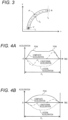
- FIG. 3 is a plan view of the first traveling route, exemplarily showing the target course P set within the range of a travelable region R where the vehicle V can travel without contacting any obstacles, pedestrians, buildings, other vehicles, or the like. Since an inflection point I 1 exists at the start point of the right turn and an inflection point I 2 exists at the end point on the target course P, the acceleration determination unit 42c defines a section from the inflection point I 1 to the inflection point I 2 as one curve C 1 . Note that, in FIG. 3 , the target course P is a route for traveling at the center of the travelable region R. However, if the target course P is within the range of the travelable region R, for example, the target course P having a peak curvature smaller than the peak curvature of the road shape may be set.
- the behavior of the vehicle V in FIG. 3 in a conventional case is compared with the behavior of the vehicle in this embodiment when the vehicle travels on the curve C 1 of the first traveling route in a so-called “slowin, first-out” manner.
- FIG. 4A is an acceleration graph when the conventional control is used for the vehicle V in FIG. 3
- FIG. 4B is an acceleration graph when the control of the first embodiment is used for the vehicle V in FIG. 3 .
- each chain line indicates the longitudinal acceleration of the vehicle V
- each broken line indicates the lateral acceleration of the vehicle V
- each solid line indicates the composite acceleration which is the square root of the sum of squares of the longitudinal acceleration and the lateral acceleration.
- the sinusoidal waveform is exemplified as the shape of the longitudinal acceleration control of the first embodiment, but for example, the shape may be a rectangular waveform or a trapezoidal waveform.
- FIG. 5 is a graph illustrating the jerk generated in the vehicle V when the acceleration control of FIG. 4B is executed. Note that the longitudinal jerk and the lateral jerk illustrated in FIG. 5 are temporal changes in longitudinal acceleration and lateral acceleration illustrated in FIG. 4B , and the composite jerk illustrated in FIG. 5 is the square root of the sum of squares of the longitudinal jerk and the lateral jerk.
- the shape of the longitudinal jerk according to the first embodiment is a sinusoidal waveform, but may be, for example, a rectangular waveform or a trapezoidal waveform, and the peak value of the composite jerk can be reduced by forming the shape of the longitudinal acceleration or the longitudinal jerk into a rectangular waveform or a trapezoidal waveform.
- FIG. 6 is a plan view of the second traveling route, exemplarily showing the target course P set within the range of the travelable region R when the vehicle V changes lanes between two adjacent straight paths. Since the inflection points I 3 , I 4 , and I 5 exist between the start point and the end point of the lane change on the target course P, the acceleration determination unit 42c defines a left turn section from the inflection point I 3 to the inflection point I 4 as one curve C 2 , and defines a right turn section from the inflection point I 4 to the inflection point I 5 as another curve C 3 .
- FIG. 7 is an acceleration graph when the control according to the present embodiment is used for the vehicle V in FIG. 6 .
- the vehicle V using the control according to the present embodiment decelerates near the entrance of the first curve C 2 and accelerates near the exit of the next curve C 3 .
- the peak value of the absolute value of the longitudinal acceleration (chain line) smaller than the peak value of the absolute value of the lateral acceleration (broken line)
- the number of peaks of the composite acceleration can be made one even while the vehicle is traveling on either the curve C 2 or the curve C 3 . Therefore, even at the time of lane change in which curves in opposite directions are continuous, the vibration generated in the vehicle V is reduced, and the occurrence of unstable behavior of the vehicle can be suppressed.
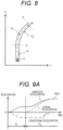
- FIG. 8 is a plan view of the third traveling route, exemplarily showing the target course P set within the range of the travelable region R of the vehicle V. Since an inflection point I 6 exists at the start point of the right turn and an inflection point I 7 exists at the end point on the target course P, the acceleration determination unit 42c defines a section up to the inflection point I 6 as a straight path S and defines a section from the inflection point I 6 to the inflection point I 7 as one curve C 4 .
- FIG. 9A is an example of an acceleration graph when the control according to the present embodiment is used for the vehicle V in FIG. 8 .
- the vehicle V starts to decelerate from the current position on the straight path S and enters the curve C 4 while decelerating.
- the peak value of the absolute value of the longitudinal acceleration (chain line) smaller than the peak value of the absolute value of the lateral acceleration (broken line)
- the number of peaks of the composite acceleration (solid line) of the curve C 4 can be made one.
- FIG. 9B illustrates an acceleration graph when the vehicle V enters curve C 4 while decelerating more quickly and greatly than in FIG. 9A .
- the peak value of the absolute value of the longitudinal acceleration (chain line) is made smaller than the peak value of the absolute value of the lateral acceleration (broken line) before the vehicle V enters the curve C 4 , so that the number of peaks of the composite acceleration (solid line) during passage through the curve C 4 can be made one.
- the vehicle motion control device of the first embodiment by controlling the relationship between the longitudinal acceleration and the lateral acceleration such that the number of peaks of the composite acceleration while the vehicle V is passing through each curve becomes one, the number of vibrations generated in the vehicle V can be reduced, and the occurrence of unstable behavior of the vehicle V can be suppressed. This improves the ride comfort and comfortable feeling of the occupants.
- FIG. 10 is a functional block diagram of a speed planning unit 42 according to the second embodiment.
- the speed planning unit 42 according to the present embodiment illustrated here is obtained by changing the traveling speed generation unit 42e to a traveling speed candidate generation unit 42f and adding a traveling speed selection unit 42g to the speed planning unit 42 according to the first embodiment illustrated in FIG. 2 .
- the traveling speed candidate generation unit 42f generates a plurality of target speed candidates whose composite acceleration has one peak on the basis of the traveling status information and the target course P from the information acquisition unit 42a, the vehicle behavior prediction value from the vehicle behavior prediction unit 42b, and the determination result (information) from the acceleration determination unit 42c and outputs the plurality of target speed candidates to the traveling speed selection unit 42g.
- the traveling speed selection unit 42g selects one candidate as the target speed based on the current traveling mode (such as the shortest time mode or the economy mode) indicated by the traveling status information from the information acquisition unit 42a and the plurality of target speed candidates from the traveling speed candidate generation unit 42f and outputs the selected candidate to a travel control unit 5. For example, when the traveling status information indicates the shortest time mode, a target speed candidate corresponding to the shortest moving time is selected from among the plurality of target speed candidates generated by the traveling speed candidate generation unit 42f, and when the traveling status information indicates the economy mode, a target speed candidate corresponding to the smallest energy consumption is selected from among the plurality of target speed candidates. That is, the traveling speed selection unit 42g selects the target speed corresponding to the shortest moving time from the plurality of target speeds or selects the target speed corresponding to the minimum energy consumption from the plurality of target speeds.
- the traveling speed selection unit 42g selects the target speed corresponding to the shortest moving time from the plurality of target speeds or selects the target speed corresponding to the
- the vehicle motion control device As described above, according to the vehicle motion control device according to the second embodiment, not only the same effects as those of the first embodiment can be obtained, but also the vehicle motion can be controlled according to the selection of the traveling mode.
- the present invention is not limited to above-described embodiments and includes various modifications.
- the above-described embodiment has been described specifically for easy understanding of the present invention, and is not necessarily limited to one having all the configurations described above.
- part of the configuration of one embodiment can be replaced with part of the configuration of another embodiment.
- the configuration of another embodiment can be added to the configuration of a certain embodiment.
- part of the configuration of each embodiment can be deleted, and part of another configuration can be added and replaced with part of another configuration.
Landscapes
- Engineering & Computer Science (AREA)
- Transportation (AREA)
- Mechanical Engineering (AREA)
- Automation & Control Theory (AREA)
- Chemical & Material Sciences (AREA)
- Combustion & Propulsion (AREA)
- Physics & Mathematics (AREA)
- Mathematical Physics (AREA)
- Human Computer Interaction (AREA)
- General Physics & Mathematics (AREA)
- Control Of Driving Devices And Active Controlling Of Vehicle (AREA)
- Traffic Control Systems (AREA)
Abstract
Description
- The present invention relates to a vehicle motion control device that controls the motion of a vehicle and a vehicle motion control method.
- As a type of vehicle motion control technology typified by driving assistance and automatic driving, there is known a technology of generating a traveling track including information such as a traveling route and a traveling speed to be traveling targets of a vehicle, and controlling a power train, a brake, a steering, and the like so that the vehicle travels along the traveling track. The simplest traveling route control is, for example, lane keeping control that sets the center of a lane as a traveling route.
- Further, as a more advanced traveling route control technique, there is a technique disclosed in
PTL 1. For example,claim 1 ofPTL 1 describes a vehicle motion control device that "when calculating the traveling track on which the vehicle is turned to one of left and right and then continuously turned to the other, calculates the traveling track such that a peak value of curvature of the traveling track decreases as a vehicle speed of the vehicle is higher on the traveling track". In addition,claim 2 describes a vehicle motion control device "calculates a difference between a maximum value of a longitudinal/lateral composite acceleration of the vehicle while the vehicle turns to one of the left and right and a maximum value of a longitudinal/lateral composite acceleration of the vehicle while the vehicle turns to the other, ..., and calculates the traveling track so that the difference is smaller than when the vehicle turns to the left and right along a point symmetrical track". - As described above,
PTL 1 discloses a vehicle motion control device that targets the calculation of a traveling track on which a vehicle is turned to one of left and right and then continuously turned to the other, that is, a vehicle motion in a lane change (lane change) mode, and that suppresses the peak value of longitudinal/lateral composite acceleration of the vehicle and improves the stability of a vehicle behavior by calculating a traveling track so that the peak value of the curvature of the traveling track decreases as the vehicle speed of the vehicle at the time of lane change increases. - PTL 1:
JP 2018-047828 A - However, the vehicle motion device of
PTL 1 does not improve the ride comfort and comfortable feeling of the occupants by suppressing the number of peaks of the composite acceleration but permits that, for example, the number of peaks of the composite acceleration increases, the number of vibrations generated in the vehicle increases, and the behavior of the vehicle becomes unstable as a result of suppressing the peak value of the composite acceleration. - Therefore, an object of the present invention is to provide a vehicle motion control device and a vehicle motion control method which reduce the vibration generated in a vehicle and suppress the occurrence of the unstable behavior of the vehicle by suppressing the number of peaks of the composite acceleration of the vehicle.
- In order to solve the above problem, a vehicle motion control device according to the present invention controls the motion of a vehicle and includes an operation management unit that generates traveling status information of the vehicle, a traveling track generation unit that generates the traveling track of the vehicle based on the traveling status information, and a travel control unit that controls driving, braking, and steering of the vehicle based on the traveling track. The traveling track generation unit includes a course planning unit that generates a target course based on the traveling status information and a speed planning unit that plans a target speed by calculating a longitudinal acceleration and a lateral acceleration whose composite acceleration has one peak when the vehicle travels on each curve in the target course.
- According to the vehicle motion control device and the vehicle motion control method of the present invention, the vibration generated in the vehicle can be reduced and the unstable behavior of the vehicle can be suppressed by suppressing the number of peaks of the composite acceleration of the vehicle. Problems, configurations, and effects other than those described above will be clarified by the following description of embodiments.
-
- [
FIG. 1] FIG. 1 is a functional block diagram of an in-vehicle system according to a first embodiment. - [
FIG. 2] FIG. 2 is a functional block diagram of a speed planning unit according to the first embodiment. - [
FIG. 3] FIG. 3 is a plan view of a first traveling route. - [
FIG. 4A] FIG. 4A is an acceleration graph when conventional control is used during traveling on a first traveling route. - [
FIG. 4B] FIG. 4B is an acceleration graph when control according to the first embodiment is used during traveling on a first traveling route. - [
FIG. 5] FIG. 5 is a jerk graph when control according to the first embodiment is used during traveling on a first traveling route. - [
FIG. 6] FIG. 6 is a plan view of a second traveling route. - [
FIG. 7] FIG. 7 is an acceleration graph when control according to the first embodiment is used during traveling on a second traveling route. - [
FIG. 8] FIG. 8 is a plan view of a third traveling route. - [
FIG. 9A] FIG. 9A is an acceleration graph when control according to the first embodiment is used during traveling on a third traveling route. - [
FIG. 9B] FIG. 9B is another example of the acceleration graph when control according to the first embodiment is used during traveling on the third traveling route. - [
FIG. 10] FIG. 10 is a functional block diagram of a speed planning unit according to the second embodiment. - Hereinafter, embodiments of a vehicle motion control device and a vehicle motion control method according to the present invention will be described with reference to the accompanying drawings. Note that substantially the same or similar configurations are denoted by the same reference numerals, and in a case where descriptions thereof overlap, the description thereof may be omitted. In addition, a description of the well-known technique may be omitted.
- First, a vehicle
motion control device 2 according to the first embodiment of the present invention will be described with reference toFIGS. 1 to 9B . -
FIG. 1 is a functional block diagram of an in-vehicle system 1 including the vehiclemotion control device 2 of the present embodiment. The in-vehicle system 1 is a system that is mounted on a vehicle and executes vehicle motion control such as driving assistance and automatic driving. As illustrated in the drawing, the in-vehicle system 1 includes an externalvehicle communication device 11, a global navigation satellite system (GNSS) 12, a mapinformation storage unit 13, asensor 14, a human machine interface (HMI)unit 15, the vehiclemotion control device 2, apower train system 6, abrake system 7, and asteering system 8. These components will be sequentially described below. - The external
vehicle communication device 11 executes vehicle-to-vehicle communication with another vehicle or road-to-vehicle communication with a roadside device by wireless communication and transmits and receives information concerning a vehicle, a surrounding environment, and the like. - The GNSS 12 receives a radio wave transmitted from an artificial satellite such as a quasi-zenith satellite or a global positioning system (GPS) satellite and acquires information such as the position of the vehicle (own vehicle).
- The map
information storage unit 13 stores general road information used in a navigation system or the like, road information having information related to curves such as the widths of roads and curvatures of roads, information such as road surface conditions and traffic conditions, and information concerning a vehicle, a surrounding environment, and the like which is information on the traveling statuses of other vehicles.
Note that the information concerning the vehicle, the surrounding environment, and the like is sequentially updated by information acquired by vehicle-to-vehicle communication or road-to-vehicle communication via the externalvehicle communication device 11. - The
sensor 14 is an external recognition sensor such as an image sensor, a millimeter-wave radar, or LiDAR that detects information concerning the vehicle, the surrounding environment, and the like, or a sensor that detects information concerning an operation by a driver, the speed, acceleration, jerk, and angular velocity of the vehicle, the steering angle of a wheel, and the like. The information concerning the vehicle, the surrounding environment, and the like detected by the external recognition sensor is, for example, information of various objects such as an obstacle, a sign, a lane boundary, a lane outside line, a building, a pedestrian, and another vehicle present around the own vehicle. Furthermore, thesensor 14 recognizes, for example, a lane boundary line, a lane outside line, and the like on the basis of the difference between a white line of image data captured by the image sensor and luminance of a road surface. - The
HMI unit 15 displays, on a display, information required by the user from information received by an input operation of the user, such as the selection of a traveling mode or the setting of a destination, information acquired by the externalvehicle communication device 11, theGNSS 12, and thesensor 14, and information recorded in the mapinformation storage unit 13, and provides voice guidance from a speaker. In addition, theHMI unit 15 generates an alarm for calling the user's attention. - In this case, the traveling mode includes, for example, a comfort mode, an economy mode, and a sports mode and is arbitrarily set by the user, or is set in advance by the user, or is set by the operation management unit 3 (to be described later) on the basis of the traveling status information, and the speed, acceleration, jerk, and the like of the vehicle are set. That is, the upper limit value of the behavior of the vehicle changes depending on the traveling mode. In addition, the traveling mode includes a shortest time mode for minimizing the moving time, a shortest distance mode for minimizing the moving distance, and the like.
- As illustrated in
FIG. 1 , the vehiclemotion control device 2 includes anoperation management unit 3, a travelingtrack generation unit 4, and atravel control unit 5, and the travelingtrack generation unit 4 includes acourse planning unit 41 and aspeed planning unit 42. Specifically, the vehiclemotion control device 2 is an electronic control unit (ECU) that includes an arithmetic device such as a central processing unit (CPU), a main storage device such as a semiconductor memory, an auxiliary storage device, and hardware such as a communication device, and integrally controls the vehicle, and implements various functions of theoperation management unit 3 and the like by executing programs loaded into the main storage device by the arithmetic device. Note that, in the present embodiment, for convenience of explanation, theoperation management unit 3, the travelingtrack generation unit 4, and thetravel control unit 5 have separate configurations, but do not necessarily have separate configurations, and when these units are used for an actual vehicle, various functions of these units may be implemented by a higherlevel controller. - The
operation management unit 3 generates information regarding the behavior of the vehicle such as information regarding the position of the host vehicle, information regarding various objects existing around the host vehicle (information regarding the vehicle, the surrounding environment, and the like), lateral acceleration, yaw rate, and lateral jerk on the basis of the information acquired by the externalvehicle communication device 11, theGNSS 12, and thesensor 14 and the information recorded in the mapinformation storage unit 13. In addition, theoperation management unit 3 periodically transmits the information of the position of the host vehicle, the information of various objects, and the information of the behavior of the vehicle to other vehicles and roadside devices via the externalvehicle communication device 11 and also transmits the information to the mapinformation storage unit 13 to sequentially update the information stored in the mapinformation storage unit 13. Further, theoperation management unit 3 sets the information of the route from the current position of the vehicle to the destination on the basis of the information of the position of the host vehicle, the information of various objects, the information of the behavior of the vehicle, and the information received by the HMI unit 15 (for example, a traveling mode or a destination). Hereinafter, the information generated or set by theoperation management unit 3 may be referred to as "traveling status information". - On the basis of the traveling status information input from the
operation management unit 3, the travelingtrack generation unit 4 generates, in thecourse planning unit 41, a route (hereinafter referred to as a "target course P") to be a travel target when the vehicle travels on the road, and generates, in thespeed planning unit 42, a speed (hereinafter referred to as a "target speed") to be a travel target when the vehicle travels on the road. Then, a traveling track including information such as the target course P and the target speed is output. Note that details of thespeed planning unit 42 will be described later. - The
travel control unit 5 sets a target driving force, a target braking force, a target steering angle, and the like so that the vehicle travels following the traveling track output from the travelingtrack generation unit 4 and controls thepower train system 6, thebrake system 7, and thesteering system 8. - The
power train system 6 controls the driving force generated by an internal combustion engine, an electric motor, or the like on the basis of an operation by a driver or the target driving force output from thetravel control unit 5. - The
brake system 7 controls the braking force generated by a brake caliper or the like based on an operation by a driver or the target braking force output from thetravel control unit 5. - The
steering system 8 controls the steering angle of the wheel based on an operation by the driver and the target steering angle output from thetravel control unit 5. - Next, details of the
speed planning unit 42 will be described with reference toFIG. 2. FIG. 2 is a functional block diagram of thespeed planning unit 42. Thespeed planning unit 42 generates the target speed of the vehicle on the basis of the position and speed of the vehicle, the upper limit value of the behavior, the target course P, and the like and includes aninformation acquisition unit 42a, a vehiclebehavior prediction unit 42b, anacceleration determination unit 42c, anacceleration correction unit 42d, and a travelingspeed generation unit 42e. These components will be sequentially described below. - The
information acquisition unit 42a acquires traveling status information from theoperation management unit 3 and the target course P from thecourse planning unit 41 and outputs them to each unit in thespeed planning unit 42. - The vehicle
behavior prediction unit 42b predicts the behavior of the vehicle at each point present on the traveling route when traveling on the target course P based on the traveling status information from theinformation acquisition unit 42a, the target course P, and an acceleration correction value from theacceleration correction unit 42d to be described later. In addition, the vehiclebehavior prediction unit 42b predicts and outputs the behavior of the vehicle equal to or less than the upper limit value that changes depending on the traveling mode set by the driver or the like or an acceleration correction value from theacceleration correction unit 42d. - Based on the traveling status information and the target course P from the
information acquisition unit 42a and the vehicle behavior prediction value from the vehiclebehavior prediction unit 42b, theacceleration determination unit 42c determines whether or not there is one peak of the composite acceleration when traveling on one curve and outputs a determination result (information). Note that the composite acceleration used here is the magnitude of a resultant vector of accelerations generated in the vehicle and is, for example, the square root of the sum of squares of the longitudinal acceleration and the lateral acceleration generated in the vehicle in the case of the planar motion of the vehicle. A peak of the composite acceleration is the maximum value of the composite acceleration generated when the vehicle travels on one curve. Note that the peak here includes a peak at which the acceleration maintains a maximum value for a predetermined time on the acceleration graph and which is in a flat state. - In order to determine whether there is one peak of the composite acceleration when traveling on one curve, the
acceleration determination unit 42c first extracts each inflection point I of the curvature of the target course P and then defines a section sandwiched by the preceding and subsequent inflection points I as one curve. Then, the number of curves (information) present in the traveling direction of the vehicle is detected, and information such as the length, width, curvature, turning direction, start point, and end point of the curve is calculated and output for each detected curve. Hereinafter, the curvature that forms a peak or an inflection point within one curve may be referred to as "peak curvature". - The
acceleration correction unit 42d calculates an acceleration correction value on the basis of the traveling status information and the target course P from theinformation acquisition unit 42a, the vehicle behavior prediction value from the vehiclebehavior prediction unit 42b, and the determination result (information) from theacceleration determination unit 42c. The acceleration correction value is a value equal to or less than the upper limit value obtained by increasing or decreasing the controllable acceleration of the vehicle calculated only when there is not one peak of the composite acceleration in one curve or changing the shape of the acceleration, and, for example, the magnitude of the longitudinal acceleration generated in the vehicle may be set to a predetermined ratio to the lateral acceleration such that there is one peak of the composite acceleration in one curve. - The traveling
speed generation unit 42e sets a speed (traveling speed) at each point present on the traveling route only when there is one peak of the composite acceleration on the basis of the traveling status information and the target course P from theinformation acquisition unit 42a, the vehicle behavior prediction value from the vehiclebehavior prediction unit 42b, and the determination result (information) from theacceleration determination unit 42c. - Next, a situation in which a vehicle V travels on the first traveling route will be described with reference to
FIGS. 3 to 5 . -
FIG. 3 is a plan view of the first traveling route, exemplarily showing the target course P set within the range of a travelable region R where the vehicle V can travel without contacting any obstacles, pedestrians, buildings, other vehicles, or the like. Since an inflection point I1 exists at the start point of the right turn and an inflection point I2 exists at the end point on the target course P, theacceleration determination unit 42c defines a section from the inflection point I1 to the inflection point I2 as one curve C1. Note that, inFIG. 3 , the target course P is a route for traveling at the center of the travelable region R. However, if the target course P is within the range of the travelable region R, for example, the target course P having a peak curvature smaller than the peak curvature of the road shape may be set. - Next, the behavior of the vehicle V in
FIG. 3 in a conventional case is compared with the behavior of the vehicle in this embodiment when the vehicle travels on the curve C1 of the first traveling route in a so-called "slowin, first-out" manner. -
FIG. 4A is an acceleration graph when the conventional control is used for the vehicle V inFIG. 3, and FIG. 4B is an acceleration graph when the control of the first embodiment is used for the vehicle V inFIG. 3 . Referring toFIGS. 4A and 4B , each chain line indicates the longitudinal acceleration of the vehicle V, each broken line indicates the lateral acceleration of the vehicle V, and each solid line indicates the composite acceleration which is the square root of the sum of squares of the longitudinal acceleration and the lateral acceleration. - As indicated by the longitudinal acceleration (chain line) in
FIG. 4A , when the vehicle V decelerates near the entrance of the curve C1 and accelerates near the exit, in the conventional control for suppressing the peak value of the composite acceleration (solid line), not only the peak of the composite acceleration occurs twice near the entrance and the exit of the curve C1, but also acceleration changes near the respective peaks become steep. - On the other hand, as illustrated in
FIG. 4B , according to the acceleration control of the present embodiment, by setting the peak value of the absolute value of the longitudinal acceleration (chain line) to be smaller than the peak value of the absolute value of the lateral acceleration (broken line), not only the peak of the composite acceleration (solid line) becomes one near the center of the curve C1, but also the acceleration change near the peak becomes gentle. - Therefore, according to the present embodiment, it can be seen that not only the number of peaks of the composite acceleration can be reduced from two to one, but also the change in acceleration can be mitigated. That is, when the acceleration control of the present embodiment is adopted, the number of vibrations generated in the vehicle V traveling on the curve C1 is reduced as compared with the conventional method, and the occurrence of unstable behavior of the vehicle can be suppressed, so that the ride comfort of the occupants is improved. Referring to
FIG. 4B , the sinusoidal waveform is exemplified as the shape of the longitudinal acceleration control of the first embodiment, but for example, the shape may be a rectangular waveform or a trapezoidal waveform. -
FIG. 5 is a graph illustrating the jerk generated in the vehicle V when the acceleration control ofFIG. 4B is executed. Note that the longitudinal jerk and the lateral jerk illustrated inFIG. 5 are temporal changes in longitudinal acceleration and lateral acceleration illustrated inFIG. 4B , and the composite jerk illustrated inFIG. 5 is the square root of the sum of squares of the longitudinal jerk and the lateral jerk. - In a case where the number of peaks of the composite acceleration is set to one as illustrated in
FIG. 4B , by minimizing the peak value of the composite jerk inFIG. 5 , the vibration generated in the vehicle V traveling on the curve C1 is further reduced, and the occurrence of the unstable behavior of the vehicle V can be further suppressed. As illustrated inFIG. 5 , the shape of the longitudinal jerk according to the first embodiment is a sinusoidal waveform, but may be, for example, a rectangular waveform or a trapezoidal waveform, and the peak value of the composite jerk can be reduced by forming the shape of the longitudinal acceleration or the longitudinal jerk into a rectangular waveform or a trapezoidal waveform. - Next, a situation where the vehicle V travels on the second traveling route will be described with reference to
FIGS. 6 and 7 . -
FIG. 6 is a plan view of the second traveling route, exemplarily showing the target course P set within the range of the travelable region R when the vehicle V changes lanes between two adjacent straight paths. Since the inflection points I3, I4, and I5 exist between the start point and the end point of the lane change on the target course P, theacceleration determination unit 42c defines a left turn section from the inflection point I3 to the inflection point I4 as one curve C2, and defines a right turn section from the inflection point I4 to the inflection point I5 as another curve C3. -
FIG. 7 is an acceleration graph when the control according to the present embodiment is used for the vehicle V inFIG. 6 . As indicated by the longitudinal acceleration (chain line), the vehicle V using the control according to the present embodiment decelerates near the entrance of the first curve C2 and accelerates near the exit of the next curve C3. In this case, by making the peak value of the absolute value of the longitudinal acceleration (chain line) smaller than the peak value of the absolute value of the lateral acceleration (broken line), the number of peaks of the composite acceleration (solid line) can be made one even while the vehicle is traveling on either the curve C2 or the curve C3. Therefore, even at the time of lane change in which curves in opposite directions are continuous, the vibration generated in the vehicle V is reduced, and the occurrence of unstable behavior of the vehicle can be suppressed. - Next, a situation in which the vehicle V travels on the third traveling route will be described with reference to
FIGS. 8 to 9B . -
FIG. 8 is a plan view of the third traveling route, exemplarily showing the target course P set within the range of the travelable region R of the vehicle V. Since an inflection point I6 exists at the start point of the right turn and an inflection point I7 exists at the end point on the target course P, theacceleration determination unit 42c defines a section up to the inflection point I6 as a straight path S and defines a section from the inflection point I6 to the inflection point I7 as one curve C4. -
FIG. 9A is an example of an acceleration graph when the control according to the present embodiment is used for the vehicle V inFIG. 8 . As indicated by the longitudinal acceleration (chain line), the vehicle V starts to decelerate from the current position on the straight path S and enters the curve C4 while decelerating. At this time, by making the peak value of the absolute value of the longitudinal acceleration (chain line) smaller than the peak value of the absolute value of the lateral acceleration (broken line), the number of peaks of the composite acceleration (solid line) of the curve C4 can be made one. -
FIG. 9B illustrates an acceleration graph when the vehicle V enters curve C4 while decelerating more quickly and greatly than inFIG. 9A . In this case, the peak value of the absolute value of the longitudinal acceleration (chain line) is made smaller than the peak value of the absolute value of the lateral acceleration (broken line) before the vehicle V enters the curve C4, so that the number of peaks of the composite acceleration (solid line) during passage through the curve C4 can be made one. - As described above, according to the vehicle motion control device of the first embodiment, by controlling the relationship between the longitudinal acceleration and the lateral acceleration such that the number of peaks of the composite acceleration while the vehicle V is passing through each curve becomes one, the number of vibrations generated in the vehicle V can be reduced, and the occurrence of unstable behavior of the vehicle V can be suppressed. This improves the ride comfort and comfortable feeling of the occupants.
- Next, a vehicle
motion control device 2 according to the second embodiment of the present invention will be described with reference toFIG. 10 . A redundant description of common points with the first embodiment will be omitted. -
FIG. 10 is a functional block diagram of aspeed planning unit 42 according to the second embodiment. Thespeed planning unit 42 according to the present embodiment illustrated here is obtained by changing the travelingspeed generation unit 42e to a traveling speedcandidate generation unit 42f and adding a travelingspeed selection unit 42g to thespeed planning unit 42 according to the first embodiment illustrated inFIG. 2 . - The traveling speed
candidate generation unit 42f generates a plurality of target speed candidates whose composite acceleration has one peak on the basis of the traveling status information and the target course P from theinformation acquisition unit 42a, the vehicle behavior prediction value from the vehiclebehavior prediction unit 42b, and the determination result (information) from theacceleration determination unit 42c and outputs the plurality of target speed candidates to the travelingspeed selection unit 42g. - The traveling
speed selection unit 42g selects one candidate as the target speed based on the current traveling mode (such as the shortest time mode or the economy mode) indicated by the traveling status information from theinformation acquisition unit 42a and the plurality of target speed candidates from the traveling speedcandidate generation unit 42f and outputs the selected candidate to atravel control unit 5. For example, when the traveling status information indicates the shortest time mode, a target speed candidate corresponding to the shortest moving time is selected from among the plurality of target speed candidates generated by the traveling speedcandidate generation unit 42f, and when the traveling status information indicates the economy mode, a target speed candidate corresponding to the smallest energy consumption is selected from among the plurality of target speed candidates. That is, the travelingspeed selection unit 42g selects the target speed corresponding to the shortest moving time from the plurality of target speeds or selects the target speed corresponding to the minimum energy consumption from the plurality of target speeds. - As described above, according to the vehicle motion control device according to the second embodiment, not only the same effects as those of the first embodiment can be obtained, but also the vehicle motion can be controlled according to the selection of the traveling mode.
- In addition, the present invention is not limited to above-described embodiments and includes various modifications.
For example, the above-described embodiment has been described specifically for easy understanding of the present invention, and is not necessarily limited to one having all the configurations described above. Further, part of the configuration of one embodiment can be replaced with part of the configuration of another embodiment. In addition, the configuration of another embodiment can be added to the configuration of a certain embodiment. In addition, part of the configuration of each embodiment can be deleted, and part of another configuration can be added and replaced with part of another configuration. -
- 1
- in-vehicle system
- 11
- external vehicle communication device
- 12
- GNSS
- 13
- map information storage unit
- 14
- sensor
- 15
- HMI unit
- 2
- vehicle motion control device
- 3
- operation management unit
- 4
- traveling track generation unit
- 41
- course planning unit
- 42
- speed planning unit
- 42a
- information acquisition unit
- 42b
- vehicle behavior prediction unit
- 42c
- acceleration determination unit
- 42d
- acceleration correction unit
- 42e
- traveling speed generation unit
- 5
- travel control unit
- 6
- power train system
- 7
- brake system
- 8
- steering system
- C
- curve
- I
- inflection point
- P
- target course
- R
- travelable region
- S
- straight path
- V
- vehicle
Claims (11)
- A vehicle motion control device that controls a motion of a vehicle, comprising:an operation management unit that generates traveling status information of the vehicle;a traveling track generation unit that generates a traveling track of the vehicle based on the traveling status information; anda travel control unit that controls driving, braking, and steering of the vehicle based on the traveling track,wherein the traveling track generation unit includesa course planning unit that generates a target course based on the traveling status information anda speed planning unit that plans a target speed by calculating a longitudinal acceleration and a lateral acceleration whose composite acceleration has one peak when the vehicle travels on each curve in the target course.
- The vehicle motion control device according to claim 1, wherein the speed planning unit sets a magnitude of the longitudinal acceleration to a predetermined ratio to the lateral acceleration.
- The vehicle motion control device according to claim 1, wherein the speed planning unit plans a longitudinal acceleration and a lateral acceleration whose composite jerk that is a temporal change in the composite acceleration has a minimum peak value.
- The vehicle motion control device according to claim 1, wherein the speed planning unit corrects an acceleration generated in the vehicle so as to be not more than an upper limit value of a vehicle behavior.
- The vehicle motion control device according to claim 1, wherein the composite acceleration is a magnitude of a resultant vector of the longitudinal acceleration and the lateral acceleration.
- The vehicle motion control device according to claim 1, wherein a peak of the composite acceleration is a maximum value of the composite acceleration generated when the vehicle travels on each curve.
- The vehicle motion control device according to claim 1, wherein the curve is a section sandwiched between inflection points on the target course.
- The vehicle motion control device according to claim 1, wherein the speed planning unit plans a plurality of target speed candidates and selects a target speed according to a traveling mode from the plurality of target speed candidates.
- The vehicle motion control device according to claim 8, wherein the speed planning unit selects a target speed corresponding to a shortest moving time from the plurality of target speed candidates when the traveling mode is a shortest time mode.
- The vehicle motion control device according to claim 8, wherein the speed planning unit selects a target speed corresponding to a minimum energy consumption from the plurality of target speed candidates when the traveling mode is an economy mode.
- A vehicle motion control method for controlling a motion of a vehicle, comprising:a first step of generating traveling status information of the vehicle;a second step of generating a target course based on the traveling status information;a third step of planning a target speed by calculating a longitudinal acceleration and a lateral acceleration whose composite acceleration has one peak when the vehicle travels on each curve in the target course; anda fourth step of controlling driving, braking, and steering of the vehicle based on the target course and the target speed.
Applications Claiming Priority (2)
| Application Number | Priority Date | Filing Date | Title |
|---|---|---|---|
| JP2020209110A JP7463264B2 (en) | 2020-12-17 | 2020-12-17 | Vehicle motion control device and vehicle motion control method |
| PCT/JP2021/041347 WO2022130842A1 (en) | 2020-12-17 | 2021-11-10 | Vehicle motion control device and vehicle motion control method |
Publications (3)
| Publication Number | Publication Date |
|---|---|
| EP4266286A1 true EP4266286A1 (en) | 2023-10-25 |
| EP4266286A4 EP4266286A4 (en) | 2024-11-20 |
| EP4266286B1 EP4266286B1 (en) | 2026-01-07 |
Family
ID=82059701
Family Applications (1)
| Application Number | Title | Priority Date | Filing Date |
|---|---|---|---|
| EP21906206.4A Active EP4266286B1 (en) | 2020-12-17 | 2021-11-10 | Vehicle motion control device and vehicle motion control method |
Country Status (5)
| Country | Link |
|---|---|
| US (1) | US12434712B2 (en) |
| EP (1) | EP4266286B1 (en) |
| JP (1) | JP7463264B2 (en) |
| CN (1) | CN116635920B (en) |
| WO (1) | WO2022130842A1 (en) |
Families Citing this family (5)
| Publication number | Priority date | Publication date | Assignee | Title |
|---|---|---|---|---|
| JP7528770B2 (en) * | 2020-12-17 | 2024-08-06 | マツダ株式会社 | Automatic Driving Control Device |
| JP7687869B2 (en) * | 2021-05-31 | 2025-06-03 | Astemo株式会社 | Vehicle integrated control device and vehicle integrated control method |
| CN115503733B (en) * | 2022-10-27 | 2025-05-16 | 苏州轻棹科技有限公司 | A method for predicting longitudinal acceleration |
| JP2024100030A (en) * | 2023-01-13 | 2024-07-26 | トヨタ自動車株式会社 | Vehicle Driving Assistance Device |
| CN118683555B (en) * | 2024-06-19 | 2024-12-31 | 重庆赛力斯凤凰智创科技有限公司 | Vehicle driving method, apparatus, computer device, and readable storage medium |
Family Cites Families (25)
| Publication number | Priority date | Publication date | Assignee | Title |
|---|---|---|---|---|
| US6523409B2 (en) * | 2001-06-08 | 2003-02-25 | Brudis & Associates, Inc. | Roadway curve advisory speed determination |
| US7107136B2 (en) * | 2001-08-29 | 2006-09-12 | Delphi Technologies, Inc. | Vehicle rollover detection and mitigation using rollover index |
| US8346476B2 (en) | 2009-05-13 | 2013-01-01 | Toyota Jidosha Kabushiki Kaisha | Vehicle running control system |
| JP4766152B2 (en) * | 2009-05-13 | 2011-09-07 | トヨタ自動車株式会社 | Vehicle travel control device |
| RU2499705C2 (en) * | 2009-08-18 | 2013-11-27 | Тойота Дзидося Кабусики Кайся | Device for control over vehicle |
| WO2011021090A2 (en) * | 2009-08-18 | 2011-02-24 | Toyota Jidosha Kabushiki Kaisha | Vehicle control system |
| RU2505432C2 (en) * | 2009-08-18 | 2014-01-27 | Тойота Дзидося Кабусики Кайся | Vehicle control system |
| US8775040B2 (en) | 2009-08-18 | 2014-07-08 | Toyota Jidosha Kabushiki Kaisha | Vehicle control system |
| JP5143103B2 (en) * | 2009-09-30 | 2013-02-13 | 日立オートモティブシステムズ株式会社 | Vehicle motion control device |
| JP5497598B2 (en) * | 2010-09-15 | 2014-05-21 | トヨタ自動車株式会社 | Vehicle control device |
| EP2537727B1 (en) * | 2011-06-22 | 2015-03-11 | Volvo Car Corporation | Method for estimating a speed profile for a vehicle |
| FR2988507B1 (en) | 2012-03-23 | 2014-04-25 | Inst Francais Des Sciences Et Technologies Des Transports De Lamenagement Et Des Reseaux | ASSISTANCE SYSTEM FOR A ROAD VEHICLE |
| DE102012016240A1 (en) * | 2012-08-16 | 2014-02-20 | GM Global Technology Operations LLC (n. d. Gesetzen des Staates Delaware) | Assistance system for a motor vehicle and method for controlling a motor vehicle |
| CN103693042A (en) * | 2013-12-03 | 2014-04-02 | 重庆交通大学 | Method for forecasting automobile running speed on mountain complicated road based on foresight track curvature |
| US20160341555A1 (en) * | 2015-05-20 | 2016-11-24 | Delphi Technologies, Inc. | System for auto-updating route-data used by a plurality of automated vehicles |
| JP2017144776A (en) * | 2016-02-15 | 2017-08-24 | 株式会社Subaru | Vehicle travel control device |
| JP6808992B2 (en) * | 2016-06-17 | 2021-01-06 | 株式会社デンソー | Driving support device |
| JP6654121B2 (en) * | 2016-09-23 | 2020-02-26 | 日立オートモティブシステムズ株式会社 | Vehicle motion control device |
| BR112020000080B1 (en) * | 2017-07-03 | 2023-10-17 | Nissan Motor Co., Ltd | VEHICLE TARGET SPEED GENERATION METHOD AND VEHICLE TARGET SPEED GENERATION DEVICE FOR VEHICLE WITH POWER STEERING |
| JP6814710B2 (en) * | 2017-08-10 | 2021-01-20 | 日立オートモティブシステムズ株式会社 | Vehicle motion control device and its method, and target trajectory generator and its method |
| JP6714552B2 (en) * | 2017-08-24 | 2020-06-24 | 本田技研工業株式会社 | Vehicle control device |
| BR112020004012A2 (en) * | 2017-08-30 | 2020-09-01 | Nissan Motor Co., Ltd. | displacement control method and displacement control device for vehicle with assisted driving |
| DE102017124954B3 (en) * | 2017-10-25 | 2019-04-18 | Dr. Ing. H.C. F. Porsche Aktiengesellschaft | Method for operating a self-driving motor vehicle |
| JP7147524B2 (en) * | 2018-12-07 | 2022-10-05 | トヨタ自動車株式会社 | vehicle controller |
| JP7798583B2 (en) * | 2022-01-20 | 2026-01-14 | Astemo株式会社 | Vehicle motion control device and vehicle motion control method |
-
2020
- 2020-12-17 JP JP2020209110A patent/JP7463264B2/en active Active
-
2021
- 2021-11-10 US US18/265,804 patent/US12434712B2/en active Active
- 2021-11-10 EP EP21906206.4A patent/EP4266286B1/en active Active
- 2021-11-10 CN CN202180083661.3A patent/CN116635920B/en active Active
- 2021-11-10 WO PCT/JP2021/041347 patent/WO2022130842A1/en not_active Ceased
Also Published As
| Publication number | Publication date |
|---|---|
| US12434712B2 (en) | 2025-10-07 |
| US20240034328A1 (en) | 2024-02-01 |
| EP4266286B1 (en) | 2026-01-07 |
| EP4266286A4 (en) | 2024-11-20 |
| CN116635920A (en) | 2023-08-22 |
| WO2022130842A1 (en) | 2022-06-23 |
| JP2022096166A (en) | 2022-06-29 |
| CN116635920B (en) | 2026-06-16 |
| JP7463264B2 (en) | 2024-04-08 |
Similar Documents
| Publication | Publication Date | Title |
|---|---|---|
| EP4266286B1 (en) | Vehicle motion control device and vehicle motion control method | |
| US11597385B2 (en) | Autonomous vehicle and vehicle running control method using the same | |
| US10943133B2 (en) | Vehicle control device, vehicle control method, and storage medium | |
| US20250145155A1 (en) | Vehicle movement control device and vehicle movement control method | |
| US11225249B2 (en) | Vehicle control device, vehicle control method, and storage medium | |
| RU2671602C1 (en) | Device for forming of a target route and the device for controlling the drive | |
| WO2017094907A1 (en) | Travel trajectory generation device and travel trajectory generation method | |
| EP4137377B1 (en) | Vehicle motion control device and vehicle motion control method | |
| EP3985641B1 (en) | Travel assistance method and travel assistance device | |
| JP7223730B2 (en) | VEHICLE CONTROL DEVICE, VEHICLE CONTROL METHOD, AND PROGRAM | |
| RU2721436C1 (en) | Driving assistance method and driving assistance device | |
| JP7250624B2 (en) | VEHICLE TRIP CONTROL METHOD AND TRIP CONTROL DEVICE | |
| JP7263827B2 (en) | VEHICLE DRIVING ASSIST METHOD AND DRIVING ASSIST DEVICE | |
| EP4350663B1 (en) | Vehicle motion control device and vehicle motion control method | |
| JP2022056602A (en) | Vehicle control device, vehicle control method, and program | |
| EP4538130A1 (en) | Vehicle motion control device, and vehicle motion control method | |
| JP7834123B2 (en) | Determination device, determination method, and program | |
| WO2025028060A1 (en) | Vehicle motion control device | |
| JP7429556B2 (en) | Vehicle control device, vehicle control method, and program | |
| WO2025094479A1 (en) | Vehicle motion control device and vehicle motion control method |
Legal Events
| Date | Code | Title | Description |
|---|---|---|---|
| STAA | Information on the status of an ep patent application or granted ep patent |
Free format text: STATUS: THE INTERNATIONAL PUBLICATION HAS BEEN MADE |
|
| PUAI | Public reference made under article 153(3) epc to a published international application that has entered the european phase |
Free format text: ORIGINAL CODE: 0009012 |
|
| STAA | Information on the status of an ep patent application or granted ep patent |
Free format text: STATUS: REQUEST FOR EXAMINATION WAS MADE |
|
| 17P | Request for examination filed |
Effective date: 20230531 |
|
| AK | Designated contracting states |
Kind code of ref document: A1 Designated state(s): AL AT BE BG CH CY CZ DE DK EE ES FI FR GB GR HR HU IE IS IT LI LT LU LV MC MK MT NL NO PL PT RO RS SE SI SK SM TR |
|
| DAV | Request for validation of the european patent (deleted) | ||
| DAX | Request for extension of the european patent (deleted) | ||
| A4 | Supplementary search report drawn up and despatched |
Effective date: 20241021 |
|
| RIC1 | Information provided on ipc code assigned before grant |
Ipc: B60W 10/20 20060101ALI20241015BHEP Ipc: B60W 10/18 20120101ALI20241015BHEP Ipc: B60W 10/04 20060101ALI20241015BHEP Ipc: B60W 30/18 20120101ALI20241015BHEP Ipc: B60W 30/14 20060101ALI20241015BHEP Ipc: B60W 60/00 20200101ALI20241015BHEP Ipc: B60W 30/182 20200101ALI20241015BHEP Ipc: B60W 30/02 20120101ALI20241015BHEP Ipc: B60W 40/109 20120101ALI20241015BHEP Ipc: B60W 40/107 20120101ALI20241015BHEP Ipc: B60W 40/072 20120101ALI20241015BHEP Ipc: G08G 1/16 20060101AFI20241015BHEP |
|
| STAA | Information on the status of an ep patent application or granted ep patent |
Free format text: STATUS: EXAMINATION IS IN PROGRESS |
|
| 17Q | First examination report despatched |
Effective date: 20250219 |
|
| GRAP | Despatch of communication of intention to grant a patent |
Free format text: ORIGINAL CODE: EPIDOSNIGR1 |
|
| STAA | Information on the status of an ep patent application or granted ep patent |
Free format text: STATUS: GRANT OF PATENT IS INTENDED |
|
| INTG | Intention to grant announced |
Effective date: 20250707 |
|
| RAP3 | Party data changed (applicant data changed or rights of an application transferred) |
Owner name: ASTEMO, LTD. |
|
| GRAS | Grant fee paid |
Free format text: ORIGINAL CODE: EPIDOSNIGR3 |
|
| GRAA | (expected) grant |
Free format text: ORIGINAL CODE: 0009210 |
|
| STAA | Information on the status of an ep patent application or granted ep patent |
Free format text: STATUS: THE PATENT HAS BEEN GRANTED |
|
| AK | Designated contracting states |
Kind code of ref document: B1 Designated state(s): AL AT BE BG CH CY CZ DE DK EE ES FI FR GB GR HR HU IE IS IT LI LT LU LV MC MK MT NL NO PL PT RO RS SE SI SK SM TR |
|
| REG | Reference to a national code |
Ref country code: CH Ref legal event code: F10 Free format text: ST27 STATUS EVENT CODE: U-0-0-F10-F00 (AS PROVIDED BY THE NATIONAL OFFICE) Effective date: 20260107 Ref country code: GB Ref legal event code: FG4D |
|
| REG | Reference to a national code |
Ref country code: DE Ref legal event code: R096 Ref document number: 602021046175 Country of ref document: DE |
|
| REG | Reference to a national code |
Ref country code: IE Ref legal event code: FG4D |
|
| REG | Reference to a national code |
Ref country code: NL Ref legal event code: MP Effective date: 20260107 |
|
| PG25 | Lapsed in a contracting state [announced via postgrant information from national office to epo] |
Ref country code: NL Free format text: LAPSE BECAUSE OF FAILURE TO SUBMIT A TRANSLATION OF THE DESCRIPTION OR TO PAY THE FEE WITHIN THE PRESCRIBED TIME-LIMIT Effective date: 20260107 |
|
| REG | Reference to a national code |
Ref country code: AT Ref legal event code: MK05 Ref document number: 1876111 Country of ref document: AT Kind code of ref document: T Effective date: 20260107 |
|
| PG25 | Lapsed in a contracting state [announced via postgrant information from national office to epo] |
Ref country code: RS Free format text: LAPSE BECAUSE OF FAILURE TO SUBMIT A TRANSLATION OF THE DESCRIPTION OR TO PAY THE FEE WITHIN THE PRESCRIBED TIME-LIMIT Effective date: 20260407 |
|
| PG25 | Lapsed in a contracting state [announced via postgrant information from national office to epo] |
Ref country code: ES Free format text: LAPSE BECAUSE OF FAILURE TO SUBMIT A TRANSLATION OF THE DESCRIPTION OR TO PAY THE FEE WITHIN THE PRESCRIBED TIME-LIMIT Effective date: 20260107 |
|
| PG25 | Lapsed in a contracting state [announced via postgrant information from national office to epo] |
Ref country code: PL Free format text: LAPSE BECAUSE OF FAILURE TO SUBMIT A TRANSLATION OF THE DESCRIPTION OR TO PAY THE FEE WITHIN THE PRESCRIBED TIME-LIMIT Effective date: 20260107 |
|
| PG25 | Lapsed in a contracting state [announced via postgrant information from national office to epo] |
Ref country code: GR Free format text: LAPSE BECAUSE OF FAILURE TO SUBMIT A TRANSLATION OF THE DESCRIPTION OR TO PAY THE FEE WITHIN THE PRESCRIBED TIME-LIMIT Effective date: 20260408 |
|
| REG | Reference to a national code |
Ref country code: LT Ref legal event code: MG9D |
|
| PG25 | Lapsed in a contracting state [announced via postgrant information from national office to epo] |
Ref country code: LT Free format text: LAPSE BECAUSE OF FAILURE TO SUBMIT A TRANSLATION OF THE DESCRIPTION OR TO PAY THE FEE WITHIN THE PRESCRIBED TIME-LIMIT Effective date: 20260107 |
|
| PG25 | Lapsed in a contracting state [announced via postgrant information from national office to epo] |
Ref country code: NO Free format text: LAPSE BECAUSE OF FAILURE TO SUBMIT A TRANSLATION OF THE DESCRIPTION OR TO PAY THE FEE WITHIN THE PRESCRIBED TIME-LIMIT Effective date: 20260407 |
|
| PG25 | Lapsed in a contracting state [announced via postgrant information from national office to epo] |
Ref country code: SE Free format text: LAPSE BECAUSE OF FAILURE TO SUBMIT A TRANSLATION OF THE DESCRIPTION OR TO PAY THE FEE WITHIN THE PRESCRIBED TIME-LIMIT Effective date: 20260107 Ref country code: FI Free format text: LAPSE BECAUSE OF FAILURE TO SUBMIT A TRANSLATION OF THE DESCRIPTION OR TO PAY THE FEE WITHIN THE PRESCRIBED TIME-LIMIT Effective date: 20260107 Ref country code: AT Free format text: LAPSE BECAUSE OF FAILURE TO SUBMIT A TRANSLATION OF THE DESCRIPTION OR TO PAY THE FEE WITHIN THE PRESCRIBED TIME-LIMIT Effective date: 20260107 |
|
| PG25 | Lapsed in a contracting state [announced via postgrant information from national office to epo] |
Ref country code: HR Free format text: LAPSE BECAUSE OF FAILURE TO SUBMIT A TRANSLATION OF THE DESCRIPTION OR TO PAY THE FEE WITHIN THE PRESCRIBED TIME-LIMIT Effective date: 20260107 |
|
| PG25 | Lapsed in a contracting state [announced via postgrant information from national office to epo] |
Ref country code: IS Free format text: LAPSE BECAUSE OF FAILURE TO SUBMIT A TRANSLATION OF THE DESCRIPTION OR TO PAY THE FEE WITHIN THE PRESCRIBED TIME-LIMIT Effective date: 20260507 Ref country code: PT Free format text: LAPSE BECAUSE OF FAILURE TO SUBMIT A TRANSLATION OF THE DESCRIPTION OR TO PAY THE FEE WITHIN THE PRESCRIBED TIME-LIMIT Effective date: 20260507 |
|
| PG25 | Lapsed in a contracting state [announced via postgrant information from national office to epo] |
Ref country code: LV Free format text: LAPSE BECAUSE OF FAILURE TO SUBMIT A TRANSLATION OF THE DESCRIPTION OR TO PAY THE FEE WITHIN THE PRESCRIBED TIME-LIMIT Effective date: 20260107 |
|
| PG25 | Lapsed in a contracting state [announced via postgrant information from national office to epo] |
Ref country code: BG Free format text: LAPSE BECAUSE OF FAILURE TO SUBMIT A TRANSLATION OF THE DESCRIPTION OR TO PAY THE FEE WITHIN THE PRESCRIBED TIME-LIMIT Effective date: 20260107 |