EP4266283A1 - Road observation device and road observation method - Google Patents
Road observation device and road observation method Download PDFInfo
- Publication number
- EP4266283A1 EP4266283A1 EP21910267.0A EP21910267A EP4266283A1 EP 4266283 A1 EP4266283 A1 EP 4266283A1 EP 21910267 A EP21910267 A EP 21910267A EP 4266283 A1 EP4266283 A1 EP 4266283A1
- Authority
- EP
- European Patent Office
- Prior art keywords
- visible range
- imaging target
- observation apparatus
- road
- recognition
- Prior art date
- Legal status (The legal status is an assumption and is not a legal conclusion. Google has not performed a legal analysis and makes no representation as to the accuracy of the status listed.)
- Granted
Links
Images



Classifications
-
- G—PHYSICS
- G06—COMPUTING OR CALCULATING; COUNTING
- G06V—IMAGE OR VIDEO RECOGNITION OR UNDERSTANDING
- G06V20/00—Scenes; Scene-specific elements
- G06V20/50—Context or environment of the image
- G06V20/52—Surveillance or monitoring of activities, e.g. for recognising suspicious objects
- G06V20/54—Surveillance or monitoring of activities, e.g. for recognising suspicious objects of traffic, e.g. cars on the road, trains or boats
-
- G—PHYSICS
- G08—SIGNALLING
- G08G—TRAFFIC CONTROL SYSTEMS
- G08G1/00—Traffic control systems for road vehicles
- G08G1/01—Detecting movement of traffic to be counted or controlled
- G08G1/04—Detecting movement of traffic to be counted or controlled using optical or ultrasonic detectors
-
- G—PHYSICS
- G06—COMPUTING OR CALCULATING; COUNTING
- G06V—IMAGE OR VIDEO RECOGNITION OR UNDERSTANDING
- G06V20/00—Scenes; Scene-specific elements
- G06V20/50—Context or environment of the image
- G06V20/56—Context or environment of the image exterior to a vehicle by using sensors mounted on the vehicle
- G06V20/58—Recognition of moving objects or obstacles, e.g. vehicles or pedestrians; Recognition of traffic objects, e.g. traffic signs, traffic lights or roads
-
- G—PHYSICS
- G06—COMPUTING OR CALCULATING; COUNTING
- G06V—IMAGE OR VIDEO RECOGNITION OR UNDERSTANDING
- G06V20/00—Scenes; Scene-specific elements
- G06V20/50—Context or environment of the image
- G06V20/56—Context or environment of the image exterior to a vehicle by using sensors mounted on the vehicle
- G06V20/58—Recognition of moving objects or obstacles, e.g. vehicles or pedestrians; Recognition of traffic objects, e.g. traffic signs, traffic lights or roads
- G06V20/584—Recognition of moving objects or obstacles, e.g. vehicles or pedestrians; Recognition of traffic objects, e.g. traffic signs, traffic lights or roads of vehicle lights or traffic lights
-
- G—PHYSICS
- G06—COMPUTING OR CALCULATING; COUNTING
- G06V—IMAGE OR VIDEO RECOGNITION OR UNDERSTANDING
- G06V20/00—Scenes; Scene-specific elements
- G06V20/50—Context or environment of the image
- G06V20/56—Context or environment of the image exterior to a vehicle by using sensors mounted on the vehicle
- G06V20/588—Recognition of the road, e.g. of lane markings; Recognition of the vehicle driving pattern in relation to the road
-
- G—PHYSICS
- G08—SIGNALLING
- G08G—TRAFFIC CONTROL SYSTEMS
- G08G1/00—Traffic control systems for road vehicles
- G08G1/01—Detecting movement of traffic to be counted or controlled
- G08G1/0104—Measuring and analyzing of parameters relative to traffic conditions
- G08G1/0108—Measuring and analyzing of parameters relative to traffic conditions based on the source of data
- G08G1/0116—Measuring and analyzing of parameters relative to traffic conditions based on the source of data from roadside infrastructure, e.g. beacons
-
- G—PHYSICS
- G08—SIGNALLING
- G08G—TRAFFIC CONTROL SYSTEMS
- G08G1/00—Traffic control systems for road vehicles
- G08G1/01—Detecting movement of traffic to be counted or controlled
- G08G1/0104—Measuring and analyzing of parameters relative to traffic conditions
- G08G1/0125—Traffic data processing
- G08G1/0133—Traffic data processing for classifying traffic situation
-
- G—PHYSICS
- G08—SIGNALLING
- G08G—TRAFFIC CONTROL SYSTEMS
- G08G1/00—Traffic control systems for road vehicles
- G08G1/01—Detecting movement of traffic to be counted or controlled
- G08G1/0104—Measuring and analyzing of parameters relative to traffic conditions
- G08G1/0137—Measuring and analyzing of parameters relative to traffic conditions for specific applications
- G08G1/0145—Measuring and analyzing of parameters relative to traffic conditions for specific applications for active traffic flow control
-
- G—PHYSICS
- G08—SIGNALLING
- G08G—TRAFFIC CONTROL SYSTEMS
- G08G1/00—Traffic control systems for road vehicles
- G08G1/09—Arrangements for giving variable traffic instructions
- G08G1/0962—Arrangements for giving variable traffic instructions having an indicator mounted inside the vehicle, e.g. giving voice messages
- G08G1/0967—Systems involving transmission of highway information, e.g. weather, speed limits
- G08G1/096733—Systems involving transmission of highway information, e.g. weather, speed limits where a selection of the information might take place
- G08G1/096741—Systems involving transmission of highway information, e.g. weather, speed limits where a selection of the information might take place where the source of the transmitted information selects which information to transmit to each vehicle
-
- G—PHYSICS
- G08—SIGNALLING
- G08G—TRAFFIC CONTROL SYSTEMS
- G08G1/00—Traffic control systems for road vehicles
- G08G1/09—Arrangements for giving variable traffic instructions
- G08G1/0962—Arrangements for giving variable traffic instructions having an indicator mounted inside the vehicle, e.g. giving voice messages
- G08G1/0967—Systems involving transmission of highway information, e.g. weather, speed limits
- G08G1/096766—Systems involving transmission of highway information, e.g. weather, speed limits where the system is characterised by the origin of the information transmission
- G08G1/096783—Systems involving transmission of highway information, e.g. weather, speed limits where the system is characterised by the origin of the information transmission where the origin of the information is a roadside individual element
-
- G—PHYSICS
- G08—SIGNALLING
- G08G—TRAFFIC CONTROL SYSTEMS
- G08G1/00—Traffic control systems for road vehicles
- G08G1/16—Anti-collision systems
- G08G1/164—Centralised systems, e.g. external to vehicles
Definitions
- the present disclosure relates to a road observation apparatus and a method for observing a road.
- Patent Literature 1 discloses shape recognition of an object with a roadside apparatus, which is a type of road observation apparatus, and a determination as to a type of object.
- Patent Literature 1 Japanese Unexamined Patent Application Publication No. 2007-272598
- a road observation apparatus includes a visible range setter that sets a visible range, which is a range within which an imaging target is recognizable, on a basis of whether a marker is recognizable and a recognition determiner that, if a distant imaging target, which is the imaging target located at a position beyond the set visible range, is recognized, initiates resetting of the visible range and that, if the reset visible range does not exceed the position of the distant imaging target, determines that the recognition of the distant imaging target is incorrect.
- a road observation apparatus includes a visible range setter that sets a visible range, which is a range within which an imaging target is recognizable, on a basis of whether a marker is recognizable and a recognition determiner that recognizes a distant imaging target, which is the imaging target located at a position beyond the set visible range, and, when the marker beyond a position of the distant imaging target is not recognized, determines that the recognition of the distant imaging target is incorrect.
- a method for observing a road includes setting a visible range, which is a range within which an imaging target is recognizable, on a basis of whether a marker is recognizable, initiating, if a distant imaging target, which is the imaging target located at a position beyond the set visible range, resetting of the visible range, and determining, if the reset visible range does not exceed the position of the distant imaging target, that the recognition of the distant imaging target is incorrect.
- FIG. 1 illustrates an example of configuration of a communication system 1 including a road observation apparatus 5 according to an embodiment.
- the communication system 1 is, for example, a safe driving assistance communication system of an intelligent transport system (ITS).
- ITS intelligent transport system
- the safe driving assistance communication system is also called a safe driving assistance system or a safe driving assistance wireless system.
- the road observation apparatus 5 is an apparatus that observes vehicles 6, objects, and humans on roads, such as a roadside apparatus or a surveillance camera apparatus.
- the road observation apparatus 5 is a roadside apparatus provided near an intersection between a plurality of roads 7 (roadways).
- the road observation apparatus 5 may be provided on a side of a road other than an intersection, instead. Details of the road observation apparatus 5 will be described later.
- the road observation apparatus 5 and vehicles 6 running on the roads 7, such as automobiles, can wirelessly communicate with each other.
- the plurality of vehicles 6 may be wirelessly capable of communicating with one another.
- electronic devices carried by pedestrians 9 may also be capable of performing wireless communication.
- the electronic devices are, for example, mobile terminal devices such as smartphones.
- the road observation apparatus 5 is capable of transmitting, to the vehicles 6, safe driving assistance information for assisting drivers of the vehicles 6 in driving safely.
- the safe driving assistance information may include, for example, information regarding lighting of signals 4, information regarding traffic rules, and road linear information indicating, for example, a shape of the intersection (shapes of the roads 7) at which the road observation apparatus 5 is provided.
- the road observation apparatus 5 also detects nearby vehicles 6 and pedestrians 9.
- the road observation apparatus 5 can detect, for example, pedestrians 9 walking across pedestrian crossings 3.
- the road observation apparatus 5 can detect vehicles 6 approaching the intersection.
- the road observation apparatus 5 is capable of transmitting, to the vehicles 6, information regarding detected vehicles 6 and pedestrians 9 while including the information in the safe driving assistance information.
- the road observation apparatus 5 is also capable of including information transmitted from one of the vehicles 6 in the safe driving assistance information and transmitting the safe driving assistance information to the other vehicles 6. As described above, the road observation apparatus 5 may be capable of transmitting these pieces of information to the electronic devices carried by the pedestrians 9.
- the vehicles 6 may, for example, regularly transmit vehicle information to the road observation apparatus 5 and other apparatuses.
- the vehicle information can include, for example, information regarding positions, speeds, and direction indicators of the vehicles 6.
- the vehicles 6 can receive various pieces of information transmitted from the road observation apparatus 5 and other apparatuses depending on electronic devices provided therefor.
- the electronic devices provided for the vehicles 6 may be, for example, automotive navigation systems.
- the electronic devices provided for the vehicles 6 can assist the drivers in driving safely by issuing notifications such as warnings to the drivers on the basis of information transmitted from the road observation apparatus 5.
- the notifications to the drivers may indicate, for example, approach of another vehicle 6 from the front when a vehicle 6 is turning at an intersection or presence of a pedestrian 9 on a pedestrian crossing 3 at an end of a turn.
- the road observation apparatus 5 is capable of transmitting safe driving assistance information based on a visible range to the vehicles 6.
- the visible range is a range within which the road observation apparatus 5 can recognize (identify) objects in images captured by a camera thereof.
- the visible range may be close to a range within which general drivers can recognize objects.
- Objects may be recognized by determining presence or absence of objects. Alternatively, objects may be recognized by determining types of objects.
- the visible range varies depending on an environment including meteorological phenomena and becomes short, for example, due to a fog.
- the road observation apparatus 5 may transmit, to the vehicles 6 as safe driving assistance information, information for prompting the drivers to decelerate to a speed at which the vehicles 6 can stop within 25 m when brakes are applied.
- the communication system 1 thus assists the drivers of the vehicles 6 in driving safely.
- the vehicles 6 are not limited to automobiles.
- the vehicles 6 can include, for example, motorcycles, buses, streetcars, and bicycles.
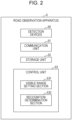
- FIG. 2 is a functional block diagram of the road observation apparatus 5 according to the embodiment.
- the road observation apparatus 5 includes detection devices 50, a communication unit 51, a storage unit 52, and a control unit 53.
- a plurality of detection devices 50 may be included.
- the plurality of detection devices 50 may be capable of operating independently of one another.
- the detection devices 50 detect the vehicles 6, the pedestrians 9, and the like.
- the detection devices 50 include sensors.
- the detection devices 50 may be, for example, visible light cameras including image sensors.
- the detection devices 50 may be infrared cameras including infrared sensors.
- the detection devices 50 include at least a visible light camera and obtain captured images by capturing images of imaging targets including markers M, which will be described later.
- the sensors included in the detection devices 50 are not limited to image sensors and infrared sensors.
- the sensors included in the detection devices 50 can include, for example, 3D laser scanners.
- the detection devices 50 output detection signals detected by the sensors and the captured images, for example, to the control unit 53.
- the communication unit 51 wirelessly communicates with the vehicles 6 under control of the control unit 53.
- the communication unit 51 may include a communication circuit and an antenna.
- the antenna may be, for example, an omnidirectional antenna.
- the communication unit 51 may perform wireless communication using, for example, a 700 MHz band assigned to the ITS.
- the communication unit 51 may perform wireless communication, for example, using a wireless LAN (local area network).
- the communication unit 51 performs various types of processing, such as amplification, on signals received by the antenna and outputs the reception signals subjected to the various types of processing to the control unit 53.
- the control unit 53 performs various types of processing on the input reception signals to obtain information included in the reception signals.
- the control unit 53 outputs transmission signals including information to the communication unit 51.
- the communication unit 51 performs various types of processing such as amplification on the input transmission signals and wirelessly transmits the transmission signals subjected to the various types of processing from the antenna.
- the storage unit 52 may have a function as a memory that stores various pieces of information.
- the storage unit 52 may store, for example, programs to be executed by the control unit 53, results of processing performed by the control unit 53, and the like.
- the storage unit 52 may function as a work memory of the control unit 53.
- the storage unit 52 may be achieved by semiconductor memories such as a ROM and a RAM, for example, but is not limited to these and may be any storage devices.
- the storage unit 52 may include, for example, a small hard disk drive and an SSD (solid-state drive).
- the storage unit 52 stores data relating to visible range setting and recognition correctness determination performed by the control unit 53.
- the storage unit 52 may store a visible range set or updated (reset) by the control unit 53.
- the storage unit 52 may also store coordinate-distance correspondence data indicating correspondences between positions (coordinates) of imaging targets in captured images and distances to the imaging targets.
- the storage unit 52 may also store a program for causing the control unit 53 to perform the visible range setting and the recognition correctness determination.
- the storage unit 52 may store a program for causing the control unit 53 to function as a visible range setting section 531 and a recognition determination section 532, which will be described later.
- the control unit 53 manages overall operation of the road observation apparatus 5 by controlling the other components of the road observation apparatus 5.
- the control unit 53 may include one or more processors.
- the processors may load programs from accessible memories and achieve various functions of the road observation apparatus 5.
- the processors may include at least a general-purpose processor that reads a certain program and that achieves a certain function or a dedicated processor specialized in a certain type of processing.
- the dedicated processor may include an application-specific integrated circuit (ASIC).
- the processors may include a programmable logic device (PLD).
- the PLD may include an FPGA (field-programmable gate array).
- the control unit 53 may include at least an SoC (system-on-a-chip) or a SiP (system-in-a-package), where one or more processors operate together.
- the control unit 53 includes the visible range setting section 531 and the recognition determination section 532.
- the visible range setting section 531 performs the visible range setting, where the visible range is set (determined), at times that will be described later, on the basis of recognition of the markers M in a captured image.
- the recognition determination section 532 performs the recognition correctness determination, where a distance to an imaging target, such as a vehicle 6 or a pedestrian 9, recognized in a captured image and the visible range are compared with each other and whether the correction of the imaging target is correct is determined. Details of the visible range setting and the recognition correctness determination will be described later.
- the control unit 53 is also capable of performing processing for transmitting information regarding the recognized vehicle 6 or pedestrian 9 to the vehicles 6 while including the information in safe driving assistance information.
- FIG. 3 is a diagram illustrating an example of the configuration of the road observation apparatus 5 according to the present embodiment.
- the road observation apparatus 5 may be provided as a road observation unit where the plurality of detection devices 50 included therein are connected to a connector 57 to define a relative positional relationship.
- the connector 57 is a member for connecting the detection devices 50.
- the connector 57 is a metal frame member.
- a material and a shape of the connector 57 are not limited.
- a Cartesian coordinate system may be defined for the road observation apparatus 5, which is the road observation unit.
- a u-axis direction, a v-axis direction, and a w-axis direction correspond to directions in which sides of the connector 57 cross at right angles at a vertex of the connector 57, respectively.
- the plurality of detection devices 50 is aligned in the w-axis direction in the road observation apparatus 5 according to the present embodiment.
- FIG. 4 illustrates an example of installation of the road observation apparatus 5.
- the road observation apparatus 5 is installed, for example, on a pole 59 near an intersection between roads 7 to be observed.
- the connector 57 may be fixed on the pole 59, and orientations of the plurality of detection devices 50 may be adjusted in relation to the connector 57.
- the w-axis direction is a vertical direction.
- a z-axis direction is the vertical direction
- an x-axis and a y-axis are horizontal directions perpendicular to a z-axis.
- the detection devices 50 may be mounted on the connector 57 via, for example, a screw, fitting, or the like and the orientations thereof may be adjusted. When the connector 57 is fixed on the pole 59, the detection devices 50 are adjusted in such a way as to be able to observe the roads from above at appropriate angles.
- the road observation apparatus 5 can recognize imaging targets (the vehicles 6, the pedestrians 9, etc.) in images captured by the detection devices 50, generate safe driving assistance information on the basis of types, motions, distances, and the like of the recognized imaging targets, and provide the safe driving assistance information.
- the detection devices 50 may recognize imaging targets through image processing such as binarization or contour detection.
- the recognition of imaging targets may include recognition of presence of imaging targets and recognition of types of imaging targets. When a recognized imaging target is beyond the visible range of the road observation apparatus 5, the recognition might not be correct. In order to provide reliable safe driving assistance information, therefore, the road observation apparatus 5 may determine that recognition of a distant imaging target beyond the visible range is incorrect.
- the visible range can vary depending on the environment including meteorological phenomena such as fogs, rain, and reflection of sunlight. If a visible range set with poor visibility, for example, continues to be used, therefore, the road observation apparatus 5 might undesirably determine that correct recognition performed after visibility is restored is incorrect. The visible range, therefore, needs to be reset at appropriate times.
- FIGs. 5 and 6 are diagrams illustrating the visible range.
- FIG. 5 illustrates how one of the detection devices 50 of the road observation apparatus 5 captures an image of markers M at certain distances from an observation position P and the captured image.
- the observation position P is a position of the detection device 50 at a time when the road observation apparatus 5 installed on the pole 59 is projected onto ground.
- the observation position P is a position at which a vertical virtual line from the detection device 50 of the road observation apparatus 5 and the ground intersect each other.
- the road observation apparatus 5 is capable of associating coordinates in a captured image and distances with each other using the markers M.
- the markers M are also called signs or indicators.
- the markers M for example, objects that hardly move, such as buildings, installations indicating bus stops or the like, or white lines drawn on the roads 7.
- the markers M may include a plurality of objects different distances away from the observation position P.
- the markers M include a marker M 1 30 m ahead of the observation position P, a marker M 2 40 m ahead of the observation position P, and a marker M 3 50 m ahead of the observation position P.
- the road observation apparatus 5 may store, in the storage unit 52, an image including the markers M captured by the detection device 50 in a desirable environment where the farthest marker M can be recognized.
- the storage unit 52 may store information regarding the distance between the observation position P and each of the markers M.
- the storage unit 52 may store information regarding a type of each of the markers M.
- the marker M 3 is located at coordinates (50, 40), which are associated with a position 50 m ahead of the observation position P.
- the marker M 2 is located at coordinates (45, 45), which are associated with a position 40 m ahead of the observation position P.
- the marker M 1 is located at coordinates (30, 60), which are associated with a position 30 m ahead of the observation position P. Coordinates of the captured image are defined with a horizontal direction represented by an X-axis, a vertical direction represented by a Y-axis, and coordinates of an upper-left corner determined as (0, 0).
- the visible range setting section 531 sets the visible range, which is a range within which an imaging target can be recognized, on the basis of whether the markers M can be recognized. When a plurality of markers M are available, the visible range setting section 531 sets a distance to, among a plurality of objects included in the markers M, a recognizable object located farthest from the observation position P as the visible range.
- the visible range setting section 531 may determine that the markers M have been recognized when contours of the markers M are detected, for example, as a result of image processing, such as edge extraction, performed on a captured image.
- the visible range setting section 531 may determine, as a result of comparison between images of the markers M included in the captured image and images of the markers M captured in a desirable environment, that the markers M have been recognized. Alternatively, the visible range setting section 531 may determine, if types of markers M can be correctly recognized, that the markers M have been recognized.
- the visible range setting section 531 recognizes all of the marker M 1 , the marker M 2 , and the marker M 3 . At this time, the visible range setting section 531 sets 50 m, which is the distance to the farthest marker M 3 , as the visible range. If there is another marker M farther than the marker M 3 and the visible range setting section 531 recognizes the other marker M, a distance corresponding to the other marker M is set as the visible range.
- FIG. 6 illustrates how the detection device 50, which is the same as in FIG. 5 , of the road observation apparatus 5 captures an image of the markers M and the captured image.
- the marker M 3 cannot be distinguished from a background and other objects due to a thick fog.
- the visible range setting section 531 sets 40 m, which is the distance to the farthest marker M 2 recognized, as the visible range.
- the road observation apparatus 5 might recognize an imaging target (distant imaging target) located at a position farther than 40 m from the observation position P.
- the term "distant” is used herein to indicate a distance beyond the visible range.
- a distant imaging target therefore, need not actually be located distant, and even when an imaging target is located 1 m away, the imaging target is referred to as being located "distant" insofar as the visible range is exceeded.
- a distant imaging target is a vehicle 6 45 m ahead of the observation position P. If a state of the fog does not change, recognition of the vehicle 6 is appropriately determined to be incorrect. If the fog clears, for example, and the visible range is restored to 50 m, however, the recognition of the vehicle 6 45 m ahead is correct.
- the recognition determination section 532 when the recognition determination section 532 recognizes a distant imaging target beyond a set visible range, the recognition determination section 532 causes the visible range setting section 531 to reset the visible range. If the reset visible range does not exceed a position of the distant imaging target, the recognition determination section 532 determines that the recognition of the distant imaging target is incorrect. If the reset visible range exceeds the position of the distant imaging target, the recognition determination section 532 determines that the recognition of the distant imaging target is correct. After a distant imaging target is recognized at a position beyond a visible range, the recognition determination section 532 thus determines, using a reset visible range appropriate for a current condition, whether the recognition of the distant imaging target is correct. The road observation apparatus 5, therefore, can correctly recognize the imaging target.
- the recognition determination section 532 may determine that an imaging target has been recognized when a contour of the imaging target has been detected as a result of image processing, such as edge extraction, performed on a captured image. Alternatively, the recognition determination section 532 may determine that an imaging target has been recognized when a type of imaging target has been recognized.
- the recognition determination section 532 may initiate the resetting of the visible range when regular update time T1 (refer to FIG. 7 ) has elapsed, in order to keep the visible range appropriate for a current condition.
- regular update time T1 is not particularly limited, but an initial value thereof may be set at, for example, 5 minutes.
- the recognition determination section 532 may increase the regular update time T 1. When the regular update time T1 varies like this, the recognition determination section 532 may reset the regular update time T1 to the initial value after a distant imaging target is recognized.
- the recognition determination section 532 When the visible range is frequently updated, a processing load of the road observation apparatus 5 increases.
- the recognition determination section 532 therefore, need not initiate the resetting of the visible range even after a distant imaging target is recognized, until retention time T0 (refer to FIG. 7 ) has elapsed since the visible range was set. In many cases, the environment including meteorological phenomena does not change very frequently.
- the retention time T0 is shorter than the regular update time T1.
- FIG. 7 is a diagram illustrating when to set the visible range and a summary of the above description.
- the recognition determination section 532 initiates the resetting of the visible range when the regular update time T1 has elapsed since the visible range was set.
- the recognition determination section 532 initiates the resetting of the visible range when the retention time T0 has elapsed since the visible range was set and then a distant imaging target is recognized. If a distant imaging target is recognized before the retention time T0 has elapsed since the visible range was set, however, the recognition determination section 532 does not initiate the resetting of the visible range.
- FIG. 8 is a flowchart illustrating a method for observing a road according to another embodiment.
- the road observation apparatus 5 observes, in accordance with the flowchart of FIG. 8 , vehicles 6, objects, and humans on roads while setting a visible range.
- the road observation apparatus 5 sets a visible range on the basis of a first captured image (step S1).
- the regular update time T1 is set at the initial value (e.g., 5 minutes) at a beginning.
- step S2 When the regular update time T1 has not elapsed since the visible range was set (No in step S2), the road observation apparatus 5 proceeds to processing in step S3.
- step S3 If a distant imaging target is recognized at a position beyond the set visible range (Yes in step S3), the road observation apparatus 5 initializes the regular update time T1 (step S4). That is, the regular update time T1 is set at the initial value.
- the road observation apparatus 5 increases the regular update time T1 (step S5). For example, the road observation apparatus 5 may set time 5 minutes longer than the regular update time T1. After increasing the regular update time T1, the road observation apparatus 5 returns to the processing in step S2.
- step S6 If the retention time T0 has elapsed since the visible range was set after the processing in step S4 (Yes in step S6), the road observation apparatus 5 resets the visible range (step S7).
- step S6 If the retention time T0 has not elapsed since the visible range was set after the processing in step S4 (No in step S6), the road observation apparatus 5 returns to the processing in step S2.
- step S7 If the processing in step S7 is the resetting based on the regular update (Yes in step S8), the road observation apparatus 5 returns to the processing in step S2.
- step S7 If the processing in step S7 is not the regular update and is the resetting as a result of recognition of a distant imaging target (No in step S8), the road observation apparatus 5 proceeds to step S9.
- step S10 determines that the recognition of the distant imaging target is incorrect. That is, if the distant imaging target exceeds the visible range even after the resetting, the road observation apparatus 5 determines that the recognition of the distant imaging target is incorrect. The road observation apparatus 5 then returns to the processing in step S2.
- step S9 the road observation apparatus 5 determines that the recognition of the distant imaging target is correct. That is, if the visible range includes the position of the distant imaging target as a result of the resetting, the road observation apparatus 5 determines that the recognition of the distant imaging target is correct. The road observation apparatus 5 then returns to the processing in step S2.
- the road observation apparatus 5 and the method for observing a road can correctly recognize an imaging target with the above configurations and steps.
- the road observation apparatus 5 is also capable of transmitting, on the basis of a reset visible range appropriate for a current condition, useful safe driving assistance information, such as a speed at which the vehicles 6 can be stopped, to the vehicles 6.
Landscapes
- Physics & Mathematics (AREA)
- General Physics & Mathematics (AREA)
- Engineering & Computer Science (AREA)
- Multimedia (AREA)
- Theoretical Computer Science (AREA)
- Chemical & Material Sciences (AREA)
- Analytical Chemistry (AREA)
- Life Sciences & Earth Sciences (AREA)
- Atmospheric Sciences (AREA)
- Traffic Control Systems (AREA)
Abstract
Description
- The present application claims priority to
Japanese Patent Application No. 2020-211815 (filed December 21, 2020 - The present disclosure relates to a road observation apparatus and a method for observing a road.
- During these years, safe driving assistance systems where a road observation apparatus is provided on a side of a road, vehicles, pedestrians, and the like are detected, and vehicles in close proximity to each other are notified of danger are being developed.
Patent Literature 1, for example, discloses shape recognition of an object with a roadside apparatus, which is a type of road observation apparatus, and a determination as to a type of object. - Patent Literature 1:
Japanese Unexamined Patent Application Publication No. 2007-272598 - In an embodiment of the present disclosure, a road observation apparatus includes a visible range setter that sets a visible range, which is a range within which an imaging target is recognizable, on a basis of whether a marker is recognizable and a recognition determiner that, if a distant imaging target, which is the imaging target located at a position beyond the set visible range, is recognized, initiates resetting of the visible range and that, if the reset visible range does not exceed the position of the distant imaging target, determines that the recognition of the distant imaging target is incorrect.
- In another embodiment of the present disclosure, a road observation apparatus includes a visible range setter that sets a visible range, which is a range within which an imaging target is recognizable, on a basis of whether a marker is recognizable and a recognition determiner that recognizes a distant imaging target, which is the imaging target located at a position beyond the set visible range, and, when the marker beyond a position of the distant imaging target is not recognized, determines that the recognition of the distant imaging target is incorrect.
- In another embodiment of the present disclosure, a method for observing a road includes setting a visible range, which is a range within which an imaging target is recognizable, on a basis of whether a marker is recognizable, initiating, if a distant imaging target, which is the imaging target located at a position beyond the set visible range, resetting of the visible range, and determining, if the reset visible range does not exceed the position of the distant imaging target, that the recognition of the distant imaging target is incorrect.
-
-
FIG. 1 is a diagram illustrating an example of configuration of a communication system including a road observation apparatus according to an embodiment. -
FIG. 2 is an example of a functional block diagram of the road observation apparatus according to the embodiment. -
FIG. 3 is a diagram illustrating an example of configuration of the road observation apparatus according to the embodiment. -
FIG. 4 is a diagram illustrating an example of installation of the road observation apparatus according to the embodiment. -
FIG. 5 is a diagram illustrating a visible range. -
FIG. 6 is another diagram illustrating the visible range. -
FIG. 7 is a diagram illustrating when to set the visible range. -
FIG. 8 is a flowchart illustrating an example of a method for observing a road according to the embodiment. -
FIG. 1 illustrates an example of configuration of acommunication system 1 including aroad observation apparatus 5 according to an embodiment. Thecommunication system 1 is, for example, a safe driving assistance communication system of an intelligent transport system (ITS). The safe driving assistance communication system is also called a safe driving assistance system or a safe driving assistance wireless system. - The
road observation apparatus 5 is an apparatus that observesvehicles 6, objects, and humans on roads, such as a roadside apparatus or a surveillance camera apparatus. In the present embodiment, theroad observation apparatus 5 is a roadside apparatus provided near an intersection between a plurality of roads 7 (roadways). Theroad observation apparatus 5 may be provided on a side of a road other than an intersection, instead. Details of theroad observation apparatus 5 will be described later. - In the
communication system 1, theroad observation apparatus 5 andvehicles 6 running on theroads 7, such as automobiles, can wirelessly communicate with each other. The plurality ofvehicles 6 may be wirelessly capable of communicating with one another. In thecommunication system 1, electronic devices carried bypedestrians 9 may also be capable of performing wireless communication. The electronic devices are, for example, mobile terminal devices such as smartphones. - The
road observation apparatus 5 is capable of transmitting, to thevehicles 6, safe driving assistance information for assisting drivers of thevehicles 6 in driving safely. The safe driving assistance information may include, for example, information regarding lighting ofsignals 4, information regarding traffic rules, and road linear information indicating, for example, a shape of the intersection (shapes of the roads 7) at which theroad observation apparatus 5 is provided. Theroad observation apparatus 5 also detectsnearby vehicles 6 andpedestrians 9. Theroad observation apparatus 5 can detect, for example,pedestrians 9 walking acrosspedestrian crossings 3. Theroad observation apparatus 5 can detectvehicles 6 approaching the intersection. Theroad observation apparatus 5 is capable of transmitting, to thevehicles 6, information regarding detectedvehicles 6 andpedestrians 9 while including the information in the safe driving assistance information. Theroad observation apparatus 5 is also capable of including information transmitted from one of thevehicles 6 in the safe driving assistance information and transmitting the safe driving assistance information to theother vehicles 6. As described above, theroad observation apparatus 5 may be capable of transmitting these pieces of information to the electronic devices carried by thepedestrians 9. - The
vehicles 6 may, for example, regularly transmit vehicle information to theroad observation apparatus 5 and other apparatuses. The vehicle information can include, for example, information regarding positions, speeds, and direction indicators of thevehicles 6. Thevehicles 6 can receive various pieces of information transmitted from theroad observation apparatus 5 and other apparatuses depending on electronic devices provided therefor. The electronic devices provided for thevehicles 6 may be, for example, automotive navigation systems. The electronic devices provided for thevehicles 6 can assist the drivers in driving safely by issuing notifications such as warnings to the drivers on the basis of information transmitted from theroad observation apparatus 5. The notifications to the drivers may indicate, for example, approach of anothervehicle 6 from the front when avehicle 6 is turning at an intersection or presence of apedestrian 9 on a pedestrian crossing 3 at an end of a turn. - In the present embodiment, the
road observation apparatus 5 is capable of transmitting safe driving assistance information based on a visible range to thevehicles 6. The visible range is a range within which theroad observation apparatus 5 can recognize (identify) objects in images captured by a camera thereof. The visible range may be close to a range within which general drivers can recognize objects. Objects may be recognized by determining presence or absence of objects. Alternatively, objects may be recognized by determining types of objects. The visible range varies depending on an environment including meteorological phenomena and becomes short, for example, due to a fog. When the visible range obtained on the basis of a captured image is 25 m, for example, theroad observation apparatus 5 may transmit, to thevehicles 6 as safe driving assistance information, information for prompting the drivers to decelerate to a speed at which thevehicles 6 can stop within 25 m when brakes are applied. - The
communication system 1 thus assists the drivers of thevehicles 6 in driving safely. Thevehicles 6 are not limited to automobiles. Thevehicles 6 can include, for example, motorcycles, buses, streetcars, and bicycles. -
FIG. 2 is a functional block diagram of theroad observation apparatus 5 according to the embodiment. Theroad observation apparatus 5 includesdetection devices 50, acommunication unit 51, astorage unit 52, and acontrol unit 53. A plurality ofdetection devices 50 may be included. The plurality ofdetection devices 50 may be capable of operating independently of one another. - The
detection devices 50 detect thevehicles 6, thepedestrians 9, and the like. Thedetection devices 50 include sensors. Thedetection devices 50 may be, for example, visible light cameras including image sensors. Thedetection devices 50 may be infrared cameras including infrared sensors. In the present embodiment, thedetection devices 50 include at least a visible light camera and obtain captured images by capturing images of imaging targets including markers M, which will be described later. - The sensors included in the
detection devices 50 are not limited to image sensors and infrared sensors. The sensors included in thedetection devices 50 can include, for example, 3D laser scanners. Thedetection devices 50 output detection signals detected by the sensors and the captured images, for example, to thecontrol unit 53. - The
communication unit 51 wirelessly communicates with thevehicles 6 under control of thecontrol unit 53. Thecommunication unit 51 may include a communication circuit and an antenna. The antenna may be, for example, an omnidirectional antenna. Thecommunication unit 51 may perform wireless communication using, for example, a 700 MHz band assigned to the ITS. Alternatively, thecommunication unit 51 may perform wireless communication, for example, using a wireless LAN (local area network). - The
communication unit 51 performs various types of processing, such as amplification, on signals received by the antenna and outputs the reception signals subjected to the various types of processing to thecontrol unit 53. Thecontrol unit 53 performs various types of processing on the input reception signals to obtain information included in the reception signals. Thecontrol unit 53 outputs transmission signals including information to thecommunication unit 51. Thecommunication unit 51 performs various types of processing such as amplification on the input transmission signals and wirelessly transmits the transmission signals subjected to the various types of processing from the antenna. - The
storage unit 52 may have a function as a memory that stores various pieces of information. Thestorage unit 52 may store, for example, programs to be executed by thecontrol unit 53, results of processing performed by thecontrol unit 53, and the like. Thestorage unit 52 may function as a work memory of thecontrol unit 53. Thestorage unit 52 may be achieved by semiconductor memories such as a ROM and a RAM, for example, but is not limited to these and may be any storage devices. Thestorage unit 52 may include, for example, a small hard disk drive and an SSD (solid-state drive). - In the present embodiment, the
storage unit 52 stores data relating to visible range setting and recognition correctness determination performed by thecontrol unit 53. Thestorage unit 52 may store a visible range set or updated (reset) by thecontrol unit 53. Thestorage unit 52 may also store coordinate-distance correspondence data indicating correspondences between positions (coordinates) of imaging targets in captured images and distances to the imaging targets. Thestorage unit 52 may also store a program for causing thecontrol unit 53 to perform the visible range setting and the recognition correctness determination. In other words, thestorage unit 52 may store a program for causing thecontrol unit 53 to function as a visiblerange setting section 531 and arecognition determination section 532, which will be described later. - The
control unit 53 manages overall operation of theroad observation apparatus 5 by controlling the other components of theroad observation apparatus 5. Thecontrol unit 53 may include one or more processors. The processors may load programs from accessible memories and achieve various functions of theroad observation apparatus 5. The processors may include at least a general-purpose processor that reads a certain program and that achieves a certain function or a dedicated processor specialized in a certain type of processing. The dedicated processor may include an application-specific integrated circuit (ASIC). The processors may include a programmable logic device (PLD). The PLD may include an FPGA (field-programmable gate array). Thecontrol unit 53 may include at least an SoC (system-on-a-chip) or a SiP (system-in-a-package), where one or more processors operate together. - In the present embodiment, the
control unit 53 includes the visiblerange setting section 531 and therecognition determination section 532. The visiblerange setting section 531 performs the visible range setting, where the visible range is set (determined), at times that will be described later, on the basis of recognition of the markers M in a captured image. Therecognition determination section 532 performs the recognition correctness determination, where a distance to an imaging target, such as avehicle 6 or apedestrian 9, recognized in a captured image and the visible range are compared with each other and whether the correction of the imaging target is correct is determined. Details of the visible range setting and the recognition correctness determination will be described later. Thecontrol unit 53 is also capable of performing processing for transmitting information regarding the recognizedvehicle 6 orpedestrian 9 to thevehicles 6 while including the information in safe driving assistance information. -
FIG. 3 is a diagram illustrating an example of the configuration of theroad observation apparatus 5 according to the present embodiment. As illustrated inFIG. 3 , theroad observation apparatus 5 may be provided as a road observation unit where the plurality ofdetection devices 50 included therein are connected to aconnector 57 to define a relative positional relationship. - The
connector 57 is a member for connecting thedetection devices 50. In the present embodiment, theconnector 57 is a metal frame member. A material and a shape of theconnector 57, however, are not limited. As illustrated inFIG. 3 , a Cartesian coordinate system may be defined for theroad observation apparatus 5, which is the road observation unit. A u-axis direction, a v-axis direction, and a w-axis direction, for example, correspond to directions in which sides of theconnector 57 cross at right angles at a vertex of theconnector 57, respectively. As illustrated inFIG. 3 , the plurality ofdetection devices 50 is aligned in the w-axis direction in theroad observation apparatus 5 according to the present embodiment. -
FIG. 4 illustrates an example of installation of theroad observation apparatus 5. Theroad observation apparatus 5 is installed, for example, on apole 59 near an intersection betweenroads 7 to be observed. Theconnector 57 may be fixed on thepole 59, and orientations of the plurality ofdetection devices 50 may be adjusted in relation to theconnector 57. When theroad observation apparatus 5 is installed in such a way as to observe the roads from above, the w-axis direction is a vertical direction. InFIG. 4 , a z-axis direction is the vertical direction, and an x-axis and a y-axis are horizontal directions perpendicular to a z-axis. - The
detection devices 50 may be mounted on theconnector 57 via, for example, a screw, fitting, or the like and the orientations thereof may be adjusted. When theconnector 57 is fixed on thepole 59, thedetection devices 50 are adjusted in such a way as to be able to observe the roads from above at appropriate angles. - As described above, the
road observation apparatus 5 can recognize imaging targets (thevehicles 6, thepedestrians 9, etc.) in images captured by thedetection devices 50, generate safe driving assistance information on the basis of types, motions, distances, and the like of the recognized imaging targets, and provide the safe driving assistance information. Thedetection devices 50 may recognize imaging targets through image processing such as binarization or contour detection. The recognition of imaging targets may include recognition of presence of imaging targets and recognition of types of imaging targets. When a recognized imaging target is beyond the visible range of theroad observation apparatus 5, the recognition might not be correct. In order to provide reliable safe driving assistance information, therefore, theroad observation apparatus 5 may determine that recognition of a distant imaging target beyond the visible range is incorrect. As described above, on the other hand, the visible range can vary depending on the environment including meteorological phenomena such as fogs, rain, and reflection of sunlight. If a visible range set with poor visibility, for example, continues to be used, therefore, theroad observation apparatus 5 might undesirably determine that correct recognition performed after visibility is restored is incorrect. The visible range, therefore, needs to be reset at appropriate times. -
FIGs. 5 and6 are diagrams illustrating the visible range.FIG. 5 illustrates how one of thedetection devices 50 of theroad observation apparatus 5 captures an image of markers M at certain distances from an observation position P and the captured image. The observation position P is a position of thedetection device 50 at a time when theroad observation apparatus 5 installed on thepole 59 is projected onto ground. In other words, the observation position P is a position at which a vertical virtual line from thedetection device 50 of theroad observation apparatus 5 and the ground intersect each other. Theroad observation apparatus 5 is capable of associating coordinates in a captured image and distances with each other using the markers M. The markers M are also called signs or indicators. As the markers M, for example, objects that hardly move, such as buildings, installations indicating bus stops or the like, or white lines drawn on theroads 7. The markers M may include a plurality of objects different distances away from the observation position P. In the example illustrated inFIGs. 5 and6 , the markers M include amarker M 1 30 m ahead of the observation position P, amarker M 2 40 m ahead of the observation position P, and amarker M 3 50 m ahead of the observation position P. Theroad observation apparatus 5 may store, in thestorage unit 52, an image including the markers M captured by thedetection device 50 in a desirable environment where the farthest marker M can be recognized. Thestorage unit 52 may store information regarding the distance between the observation position P and each of the markers M. Thestorage unit 52 may store information regarding a type of each of the markers M. - In the captured image illustrated in
FIG. 5 , the marker M3 is located at coordinates (50, 40), which are associated with aposition 50 m ahead of the observation position P. The marker M2 is located at coordinates (45, 45), which are associated with aposition 40 m ahead of the observation position P. The marker M1 is located at coordinates (30, 60), which are associated with aposition 30 m ahead of the observation position P. Coordinates of the captured image are defined with a horizontal direction represented by an X-axis, a vertical direction represented by a Y-axis, and coordinates of an upper-left corner determined as (0, 0). - The visible
range setting section 531 sets the visible range, which is a range within which an imaging target can be recognized, on the basis of whether the markers M can be recognized. When a plurality of markers M are available, the visiblerange setting section 531 sets a distance to, among a plurality of objects included in the markers M, a recognizable object located farthest from the observation position P as the visible range. The visiblerange setting section 531 may determine that the markers M have been recognized when contours of the markers M are detected, for example, as a result of image processing, such as edge extraction, performed on a captured image. Alternatively, the visiblerange setting section 531 may determine, as a result of comparison between images of the markers M included in the captured image and images of the markers M captured in a desirable environment, that the markers M have been recognized. Alternatively, the visiblerange setting section 531 may determine, if types of markers M can be correctly recognized, that the markers M have been recognized. - In the example illustrated in
FIG. 5 , the visiblerange setting section 531 recognizes all of the marker M1, the marker M2, and the marker M3. At this time, the visiblerange setting section 531 sets 50 m, which is the distance to the farthest marker M3, as the visible range. If there is another marker M farther than the marker M3 and the visiblerange setting section 531 recognizes the other marker M, a distance corresponding to the other marker M is set as the visible range. -
FIG. 6 illustrates how thedetection device 50, which is the same as inFIG. 5 , of theroad observation apparatus 5 captures an image of the markers M and the captured image. In the example illustrated inFIG. 6 , the marker M3 cannot be distinguished from a background and other objects due to a thick fog. In this situation, the visiblerange setting section 531 sets 40 m, which is the distance to the farthest marker M2 recognized, as the visible range. After the visible range is set at 40 m, theroad observation apparatus 5 might recognize an imaging target (distant imaging target) located at a position farther than 40 m from the observation position P. The term "distant" is used herein to indicate a distance beyond the visible range. A distant imaging target, therefore, need not actually be located distant, and even when an imaging target is located 1 m away, the imaging target is referred to as being located "distant" insofar as the visible range is exceeded. In the example illustrated inFIG. 6 , a distant imaging target is avehicle 6 45 m ahead of the observation position P. If a state of the fog does not change, recognition of thevehicle 6 is appropriately determined to be incorrect. If the fog clears, for example, and the visible range is restored to 50 m, however, the recognition of thevehicle 6 45 m ahead is correct. - In the present embodiment, when the
recognition determination section 532 recognizes a distant imaging target beyond a set visible range, therecognition determination section 532 causes the visiblerange setting section 531 to reset the visible range. If the reset visible range does not exceed a position of the distant imaging target, therecognition determination section 532 determines that the recognition of the distant imaging target is incorrect. If the reset visible range exceeds the position of the distant imaging target, therecognition determination section 532 determines that the recognition of the distant imaging target is correct. After a distant imaging target is recognized at a position beyond a visible range, therecognition determination section 532 thus determines, using a reset visible range appropriate for a current condition, whether the recognition of the distant imaging target is correct. Theroad observation apparatus 5, therefore, can correctly recognize the imaging target. As in the recognition of the markers M performed by the visiblerange setting section 531, therecognition determination section 532 may determine that an imaging target has been recognized when a contour of the imaging target has been detected as a result of image processing, such as edge extraction, performed on a captured image. Alternatively, therecognition determination section 532 may determine that an imaging target has been recognized when a type of imaging target has been recognized. - Even if a distant imaging target is not recognized, the
recognition determination section 532 may initiate the resetting of the visible range when regular update time T1 (refer toFIG. 7 ) has elapsed, in order to keep the visible range appropriate for a current condition. When the visible range is reset after the regular update time T1 elapses, the visible range can be kept appropriate for a current operation environment, for example, even with aroad observation apparatus 5 that observesroads 7 with little traffic. The regular update time T1 is not particularly limited, but an initial value thereof may be set at, for example, 5 minutes. - If the visible range does not change after regular update, intervals of the update may be increased. If a distant imaging target, that is, an imaging target at a position beyond a set visible range, is not recognized, the
recognition determination section 532 may increase the regularupdate time T 1. When the regular update time T1 varies like this, therecognition determination section 532 may reset the regular update time T1 to the initial value after a distant imaging target is recognized. - When the visible range is frequently updated, a processing load of the
road observation apparatus 5 increases. Therecognition determination section 532, therefore, need not initiate the resetting of the visible range even after a distant imaging target is recognized, until retention time T0 (refer toFIG. 7 ) has elapsed since the visible range was set. In many cases, the environment including meteorological phenomena does not change very frequently. The retention time T0 is shorter than the regular update time T1. -
FIG. 7 is a diagram illustrating when to set the visible range and a summary of the above description. As illustrated inFIG. 7 , even if a distant imaging target is not recognized, therecognition determination section 532 initiates the resetting of the visible range when the regular update time T1 has elapsed since the visible range was set. Therecognition determination section 532 initiates the resetting of the visible range when the retention time T0 has elapsed since the visible range was set and then a distant imaging target is recognized. If a distant imaging target is recognized before the retention time T0 has elapsed since the visible range was set, however, therecognition determination section 532 does not initiate the resetting of the visible range. -
FIG. 8 is a flowchart illustrating a method for observing a road according to another embodiment. Theroad observation apparatus 5 observes, in accordance with the flowchart ofFIG. 8 ,vehicles 6, objects, and humans on roads while setting a visible range. - The
road observation apparatus 5 sets a visible range on the basis of a first captured image (step S1). - When the regular update time T1 has elapsed since the visible range was set (Yes in step S2), the
road observation apparatus 5 proceeds to processing in step S7. The regular update time T1 is set at the initial value (e.g., 5 minutes) at a beginning. - When the regular update time T1 has not elapsed since the visible range was set (No in step S2), the
road observation apparatus 5 proceeds to processing in step S3. - If a distant imaging target is recognized at a position beyond the set visible range (Yes in step S3), the
road observation apparatus 5 initializes the regular update time T1 (step S4). That is, the regular update time T1 is set at the initial value. - If a distant imaging target is not recognized (No in step S3), the
road observation apparatus 5 increases the regular update time T1 (step S5). For example, theroad observation apparatus 5 may settime 5 minutes longer than the regular update time T1. After increasing the regular update time T1, theroad observation apparatus 5 returns to the processing in step S2. - If the retention time T0 has elapsed since the visible range was set after the processing in step S4 (Yes in step S6), the
road observation apparatus 5 resets the visible range (step S7). - If the retention time T0 has not elapsed since the visible range was set after the processing in step S4 (No in step S6), the
road observation apparatus 5 returns to the processing in step S2. - If the processing in step S7 is the resetting based on the regular update (Yes in step S8), the
road observation apparatus 5 returns to the processing in step S2. - If the processing in step S7 is not the regular update and is the resetting as a result of recognition of a distant imaging target (No in step S8), the
road observation apparatus 5 proceeds to step S9. - If the reset visible range does not exceed a position of the distant imaging target (Yes in step S9), the
road observation apparatus 5 determines that the recognition of the distant imaging target is incorrect (step S10). That is, if the distant imaging target exceeds the visible range even after the resetting, theroad observation apparatus 5 determines that the recognition of the distant imaging target is incorrect. Theroad observation apparatus 5 then returns to the processing in step S2. - If the reset visible range exceeds the position of the distant imaging target (No in step S9), the
road observation apparatus 5 determines that the recognition of the distant imaging target is correct (step S11). That is, if the visible range includes the position of the distant imaging target as a result of the resetting, theroad observation apparatus 5 determines that the recognition of the distant imaging target is correct. Theroad observation apparatus 5 then returns to the processing in step S2. - As described above, in the present embodiment, the
road observation apparatus 5 and the method for observing a road can correctly recognize an imaging target with the above configurations and steps. Theroad observation apparatus 5 is also capable of transmitting, on the basis of a reset visible range appropriate for a current condition, useful safe driving assistance information, such as a speed at which thevehicles 6 can be stopped, to thevehicles 6. - Although the present disclosure has been described on the basis of the drawings and the examples, those skilled in the art can easily alter or correct the examples on the basis of the present disclosure. The scope of the present disclosure, therefore, also includes such alterations and corrections.
-
- 1
- communication system
- 3
- pedestrian crossing
- 4
- signal
- 5
- road observation apparatus
- 6
- vehicle
- 7
- road
- 9
- pedestrian
- 50
- detection device
- 51
- communication unit
- 52
- storage unit
- 53
- control unit
- 57
- connector
- 59
- pole
- 531
- visible range setting section
- 532
- recognition determination section
Claims (8)
- A road observation apparatus comprising:a visible range setter that sets a visible range, which is a range within which an imaging target is recognizable, on a basis of whether a marker is recognizable; anda recognition determiner that, if a distant imaging target, which is the imaging target located at a position beyond the set visible range, is recognized, initiates resetting of the visible range and that, if the reset visible range does not exceed the position of the distant imaging target, determines that the recognition of the distant imaging target is incorrect.
- The road observation apparatus according to claim 1,wherein the marker includes a plurality of objects different distances away from an observation position, andwherein the visible range setter sets, as the visible range, a distance to, among the plurality of objects included in the marker, a recognizable object farthest from the observation position.
- The road observation apparatus according to claim 1 or 2,
wherein, if the reset visible range exceeds the position of the distant imaging target, the recognition determiner determines that the recognition of the distant imaging target is correct. - The road observation apparatus according to any of claims 1 to 3,
wherein, when regular update time has elapsed since the visible range was set, the recognition determiner initiates the resetting of the visible range. - The road observation apparatus according to claim 4,
wherein, if the distant imaging target is not recognized, the recognition determiner increases the regular update time. - The road observation apparatus according to claim 4 or 5,
wherein, even if the distant imaging target is recognized, the recognition determiner does not initiate the resetting of the visible range until retention time, which is shorter than the regular update time, has elapsed since the visible range was set. - A road observation apparatus comprising:a visible range setter that sets a visible range, which is a range within which an imaging target is recognizable, on a basis of whether a marker is recognizable; anda recognition determiner that recognizes a distant imaging target, which is the imaging target located at a position beyond the set visible range, and, when the marker beyond a position of the distant imaging target is not recognizable, determines that the recognition of the distant imaging target is incorrect.
- A method for observing a road, the method comprising:setting a visible range, which is a range within which an imaging target is recognizable, on a basis of whether a marker is recognizable;initiating, if a distant imaging target, which is the imaging target located at a position beyond the set visible range, resetting of the visible range; anddetermining, if the reset visible range does not exceed the position of the distant imaging target, that the recognition of the distant imaging target is incorrect.
Applications Claiming Priority (2)
| Application Number | Priority Date | Filing Date | Title |
|---|---|---|---|
| JP2020211815A JP7514758B2 (en) | 2020-12-21 | 2020-12-21 | Road observation device and road observation method |
| PCT/JP2021/044761 WO2022138117A1 (en) | 2020-12-21 | 2021-12-06 | Road observation device and road observation method |
Publications (3)
| Publication Number | Publication Date |
|---|---|
| EP4266283A1 true EP4266283A1 (en) | 2023-10-25 |
| EP4266283A4 EP4266283A4 (en) | 2024-11-20 |
| EP4266283B1 EP4266283B1 (en) | 2026-05-06 |
Family
ID=82159587
Family Applications (1)
| Application Number | Title | Priority Date | Filing Date |
|---|---|---|---|
| EP21910267.0A Active EP4266283B1 (en) | 2020-12-21 | 2021-12-06 | Road observation device and road observation method |
Country Status (5)
| Country | Link |
|---|---|
| US (1) | US20240020982A1 (en) |
| EP (1) | EP4266283B1 (en) |
| JP (1) | JP7514758B2 (en) |
| CN (1) | CN116583890A (en) |
| WO (1) | WO2022138117A1 (en) |
Family Cites Families (16)
| Publication number | Priority date | Publication date | Assignee | Title |
|---|---|---|---|---|
| JP2004178239A (en) * | 2002-11-27 | 2004-06-24 | Hitachi Ltd | Driving support road system |
| JP4397164B2 (en) * | 2003-01-14 | 2010-01-13 | トヨタ自動車株式会社 | Obstacle detection device and obstacle detection method |
| JP2004317309A (en) * | 2003-04-16 | 2004-11-11 | Mts Institute Inc | Visibility calculation system and its program |
| JP2006127058A (en) * | 2004-10-27 | 2006-05-18 | Sumitomo Electric Ind Ltd | Object recognition system and image processing apparatus |
| JP2007272598A (en) | 2006-03-31 | 2007-10-18 | Denso It Laboratory Inc | Information device for operating state of safety driving support service |
| JP5659913B2 (en) * | 2011-03-30 | 2015-01-28 | 富士通株式会社 | Alarm device, alarm system, and alarm method |
| KR101957943B1 (en) * | 2012-08-31 | 2019-07-04 | 삼성전자주식회사 | Method and vehicle for providing information |
| US20160275359A1 (en) * | 2013-12-26 | 2016-09-22 | Mitsubishi Electric Corporation | Information processing apparatus, information processing method, and computer readable medium storing a program |
| JP2018073049A (en) * | 2016-10-27 | 2018-05-10 | 株式会社リコー | Image recognition device, image recognition system, and image recognition method |
| CN106448223B (en) * | 2016-11-10 | 2019-12-13 | 石家庄市长兴惠达科技有限公司 | Expressway driving speed early warning device and method capable of automatically adapting to haze |
| DE102017106952A1 (en) * | 2017-03-31 | 2018-10-04 | Connaught Electronics Ltd. | DISTANCE CONTROL FOR A VEHICLE WITH TRAILER |
| WO2019169604A1 (en) * | 2018-03-08 | 2019-09-12 | Baidu.Com Times Technology (Beijing) Co., Ltd. | Simulation-based method to evaluate perception requirement for autonomous driving vehicles |
| JP7084238B2 (en) * | 2018-07-11 | 2022-06-14 | 株式会社アイシン | Driving support system and driving support program |
| DE102018118215B4 (en) * | 2018-07-27 | 2020-04-16 | Man Truck & Bus Se | Method for updating a map of the surroundings, device for carrying out method steps of the method on the vehicle, vehicle, device for carrying out method steps of the method on the central computer, and computer-readable storage medium |
| CN108833795B (en) * | 2018-08-29 | 2020-06-19 | 北京七鑫易维信息技术有限公司 | Focusing method and device of image acquisition equipment |
| JP7081444B2 (en) * | 2018-11-01 | 2022-06-07 | トヨタ自動車株式会社 | Vehicle control system |
-
2020
- 2020-12-21 JP JP2020211815A patent/JP7514758B2/en active Active
-
2021
- 2021-12-06 EP EP21910267.0A patent/EP4266283B1/en active Active
- 2021-12-06 CN CN202180083836.0A patent/CN116583890A/en active Pending
- 2021-12-06 US US18/256,186 patent/US20240020982A1/en active Pending
- 2021-12-06 WO PCT/JP2021/044761 patent/WO2022138117A1/en not_active Ceased
Also Published As
| Publication number | Publication date |
|---|---|
| EP4266283A4 (en) | 2024-11-20 |
| JP7514758B2 (en) | 2024-07-11 |
| EP4266283B1 (en) | 2026-05-06 |
| US20240020982A1 (en) | 2024-01-18 |
| WO2022138117A1 (en) | 2022-06-30 |
| JP2022098331A (en) | 2022-07-01 |
| CN116583890A (en) | 2023-08-11 |
Similar Documents
| Publication | Publication Date | Title |
|---|---|---|
| US20230005275A1 (en) | Vehicular control system | |
| US11157751B2 (en) | Traffic guide object recognition device, traffic guide object recognition method, and storage medium | |
| US9583003B2 (en) | Vehicle danger notification control apparatus | |
| US9809223B2 (en) | Driving assistant for vehicles | |
| US9884585B1 (en) | Exterior vehicle alerting system | |
| US8854458B2 (en) | Object detection device | |
| CN107430822B (en) | Object detection device and object detection method | |
| US11119210B2 (en) | Vehicle control device and vehicle control method | |
| US11074818B2 (en) | Drive assist device and drive assist method | |
| CN107408346B (en) | Vehicle control device and vehicle control method | |
| EP3709279A1 (en) | Target detection device for vehicle | |
| JP7275623B2 (en) | Driving support device | |
| CN110164182B (en) | Vehicle awareness data collection system and method | |
| JP7229052B2 (en) | vehicle control device, vehicle control system | |
| US11086007B2 (en) | Target detection device | |
| CN110962744A (en) | Vehicle blind area detection method and vehicle blind area detection system | |
| CN113884090A (en) | Intelligent platform vehicle environment sensing system and data fusion method thereof | |
| US20190031205A1 (en) | Distinguish between vehicle turn and lane change | |
| EP3223188A1 (en) | A vehicle environment mapping system | |
| US12384363B2 (en) | Driver assistance system and computer-readable recording medium | |
| EP4266283A1 (en) | Road observation device and road observation method | |
| JP5606468B2 (en) | Vehicle periphery monitoring device | |
| JP2025069401A (en) | Observation equipment | |
| WO2018021444A1 (en) | Object detection apparatus | |
| CN113474225A (en) | Brake assist control device, brake assist system, and brake assist control method in vehicle |
Legal Events
| Date | Code | Title | Description |
|---|---|---|---|
| STAA | Information on the status of an ep patent application or granted ep patent |
Free format text: STATUS: THE INTERNATIONAL PUBLICATION HAS BEEN MADE |
|
| PUAI | Public reference made under article 153(3) epc to a published international application that has entered the european phase |
Free format text: ORIGINAL CODE: 0009012 |
|
| STAA | Information on the status of an ep patent application or granted ep patent |
Free format text: STATUS: REQUEST FOR EXAMINATION WAS MADE |
|
| 17P | Request for examination filed |
Effective date: 20230605 |
|
| AK | Designated contracting states |
Kind code of ref document: A1 Designated state(s): AL AT BE BG CH CY CZ DE DK EE ES FI FR GB GR HR HU IE IS IT LI LT LU LV MC MK MT NL NO PL PT RO RS SE SI SK SM TR |
|
| DAV | Request for validation of the european patent (deleted) | ||
| DAX | Request for extension of the european patent (deleted) | ||
| A4 | Supplementary search report drawn up and despatched |
Effective date: 20241018 |
|
| RIC1 | Information provided on ipc code assigned before grant |
Ipc: G08G 1/09 20060101ALI20241014BHEP Ipc: G08G 1/04 20060101AFI20241014BHEP |
|
| GRAP | Despatch of communication of intention to grant a patent |
Free format text: ORIGINAL CODE: EPIDOSNIGR1 |
|
| STAA | Information on the status of an ep patent application or granted ep patent |
Free format text: STATUS: GRANT OF PATENT IS INTENDED |
|
| INTG | Intention to grant announced |
Effective date: 20251202 |
|
| GRAS | Grant fee paid |
Free format text: ORIGINAL CODE: EPIDOSNIGR3 |
|
| GRAA | (expected) grant |
Free format text: ORIGINAL CODE: 0009210 |
|
| STAA | Information on the status of an ep patent application or granted ep patent |
Free format text: STATUS: THE PATENT HAS BEEN GRANTED |