EP4266263A1 - Method of determining parking area layout - Google Patents
Method of determining parking area layout Download PDFInfo
- Publication number
- EP4266263A1 EP4266263A1 EP23164699.3A EP23164699A EP4266263A1 EP 4266263 A1 EP4266263 A1 EP 4266263A1 EP 23164699 A EP23164699 A EP 23164699A EP 4266263 A1 EP4266263 A1 EP 4266263A1
- Authority
- EP
- European Patent Office
- Prior art keywords
- parking
- layout
- vehicle
- slot
- parking area
- Prior art date
- Legal status (The legal status is an assumption and is not a legal conclusion. Google has not performed a legal analysis and makes no representation as to the accuracy of the status listed.)
- Granted
Links
Images

Classifications
-
- G—PHYSICS
- G08—SIGNALLING
- G08G—TRAFFIC CONTROL SYSTEMS
- G08G1/00—Traffic control systems for road vehicles
- G08G1/01—Detecting movement of traffic to be counted or controlled
- G08G1/0104—Measuring and analyzing of parameters relative to traffic conditions
- G08G1/0108—Measuring and analyzing of parameters relative to traffic conditions based on the source of data
- G08G1/0112—Measuring and analyzing of parameters relative to traffic conditions based on the source of data from the vehicle, e.g. floating car data [FCD]
-
- B—PERFORMING OPERATIONS; TRANSPORTING
- B60—VEHICLES IN GENERAL
- B60W—CONJOINT CONTROL OF VEHICLE SUB-UNITS OF DIFFERENT TYPE OR DIFFERENT FUNCTION; CONTROL SYSTEMS SPECIALLY ADAPTED FOR HYBRID VEHICLES; ROAD VEHICLE DRIVE CONTROL SYSTEMS FOR PURPOSES NOT RELATED TO THE CONTROL OF A PARTICULAR SUB-UNIT
- B60W30/00—Purposes of road vehicle drive control systems not related to the control of a particular sub-unit, e.g. of systems using conjoint control of vehicle sub-units
- B60W30/06—Automatic manoeuvring for parking
-
- G—PHYSICS
- G06—COMPUTING OR CALCULATING; COUNTING
- G06V—IMAGE OR VIDEO RECOGNITION OR UNDERSTANDING
- G06V20/00—Scenes; Scene-specific elements
- G06V20/50—Context or environment of the image
- G06V20/56—Context or environment of the image exterior to a vehicle by using sensors mounted on the vehicle
- G06V20/58—Recognition of moving objects or obstacles, e.g. vehicles or pedestrians; Recognition of traffic objects, e.g. traffic signs, traffic lights or roads
- G06V20/586—Recognition of moving objects or obstacles, e.g. vehicles or pedestrians; Recognition of traffic objects, e.g. traffic signs, traffic lights or roads of parking space
-
- B—PERFORMING OPERATIONS; TRANSPORTING
- B60—VEHICLES IN GENERAL
- B60W—CONJOINT CONTROL OF VEHICLE SUB-UNITS OF DIFFERENT TYPE OR DIFFERENT FUNCTION; CONTROL SYSTEMS SPECIALLY ADAPTED FOR HYBRID VEHICLES; ROAD VEHICLE DRIVE CONTROL SYSTEMS FOR PURPOSES NOT RELATED TO THE CONTROL OF A PARTICULAR SUB-UNIT
- B60W60/00—Drive control systems specially adapted for autonomous road vehicles
- B60W60/001—Planning or execution of driving tasks
- B60W60/0025—Planning or execution of driving tasks specially adapted for specific operations
-
- G—PHYSICS
- G01—MEASURING; TESTING
- G01C—MEASURING DISTANCES, LEVELS OR BEARINGS; SURVEYING; NAVIGATION; GYROSCOPIC INSTRUMENTS; PHOTOGRAMMETRY OR VIDEOGRAMMETRY
- G01C21/00—Navigation; Navigational instruments not provided for in groups G01C1/00 - G01C19/00
- G01C21/38—Electronic maps specially adapted for navigation; Updating thereof
- G01C21/3804—Creation or updating of map data
- G01C21/3807—Creation or updating of map data characterised by the type of data
- G01C21/3815—Road data
-
- G—PHYSICS
- G01—MEASURING; TESTING
- G01C—MEASURING DISTANCES, LEVELS OR BEARINGS; SURVEYING; NAVIGATION; GYROSCOPIC INSTRUMENTS; PHOTOGRAMMETRY OR VIDEOGRAMMETRY
- G01C21/00—Navigation; Navigational instruments not provided for in groups G01C1/00 - G01C19/00
- G01C21/38—Electronic maps specially adapted for navigation; Updating thereof
- G01C21/3804—Creation or updating of map data
- G01C21/3833—Creation or updating of map data characterised by the source of data
-
- G—PHYSICS
- G05—CONTROLLING; REGULATING
- G05D—SYSTEMS FOR CONTROLLING OR REGULATING NON-ELECTRIC VARIABLES
- G05D1/00—Control of position, course, altitude or attitude of land, water, air or space vehicles, e.g. using automatic pilots
- G05D1/0088—Control of position, course, altitude or attitude of land, water, air or space vehicles, e.g. using automatic pilots characterized by the autonomous decision making process, e.g. artificial intelligence, predefined behaviours
-
- G—PHYSICS
- G08—SIGNALLING
- G08G—TRAFFIC CONTROL SYSTEMS
- G08G1/00—Traffic control systems for road vehicles
- G08G1/01—Detecting movement of traffic to be counted or controlled
- G08G1/0104—Measuring and analyzing of parameters relative to traffic conditions
- G08G1/0125—Traffic data processing
-
- G—PHYSICS
- G08—SIGNALLING
- G08G—TRAFFIC CONTROL SYSTEMS
- G08G1/00—Traffic control systems for road vehicles
- G08G1/01—Detecting movement of traffic to be counted or controlled
- G08G1/048—Detecting movement of traffic to be counted or controlled with provision for compensation of environmental or other condition, e.g. snow, vehicle stopped at detector
-
- G—PHYSICS
- G08—SIGNALLING
- G08G—TRAFFIC CONTROL SYSTEMS
- G08G1/00—Traffic control systems for road vehicles
- G08G1/14—Traffic control systems for road vehicles indicating individual free spaces in parking areas
-
- G—PHYSICS
- G08—SIGNALLING
- G08G—TRAFFIC CONTROL SYSTEMS
- G08G1/00—Traffic control systems for road vehicles
- G08G1/14—Traffic control systems for road vehicles indicating individual free spaces in parking areas
- G08G1/141—Traffic control systems for road vehicles indicating individual free spaces in parking areas with means giving the indication of available parking spaces
-
- G—PHYSICS
- G08—SIGNALLING
- G08G—TRAFFIC CONTROL SYSTEMS
- G08G1/00—Traffic control systems for road vehicles
- G08G1/16—Anti-collision systems
- G08G1/168—Driving aids for parking, e.g. acoustic or visual feedback on parking space
-
- B—PERFORMING OPERATIONS; TRANSPORTING
- B60—VEHICLES IN GENERAL
- B60W—CONJOINT CONTROL OF VEHICLE SUB-UNITS OF DIFFERENT TYPE OR DIFFERENT FUNCTION; CONTROL SYSTEMS SPECIALLY ADAPTED FOR HYBRID VEHICLES; ROAD VEHICLE DRIVE CONTROL SYSTEMS FOR PURPOSES NOT RELATED TO THE CONTROL OF A PARTICULAR SUB-UNIT
- B60W2556/00—Input parameters relating to data
- B60W2556/40—High definition maps
Definitions
- the present disclosure relates to a computer-implemented method of determining a layout for a parking area.
- the parking area may be a parking lot or a region of a parking lot.
- Such a method can be used for example by a vehicle to determine a parking area layout and control the vehicle to move within the parking area based on the parking area layout, in an automated or partially automated manner.
- parking systems In the automotive field, parking systems have been developed to control the vehicle in executing parking maneuvers in an automated manner or partially automated manner.
- the parking systems rely on multiple sensors, e.g. vision sensors, Lidar sensors, radar sensors, Global Navigation Satellite System (GNSS), and a perception stack to collect information about a surrounding environment of the vehicle, and detect a free or unoccupied parking slot, also termed as parking space. Once a free parking slot has been detected and confirmed, the parking system starts planning a parking maneuver and then controls at least partially the vehicle to execute the planned parking maneuver.
- sensors e.g. vision sensors, Lidar sensors, radar sensors, Global Navigation Satellite System (GNSS), and a perception stack to collect information about a surrounding environment of the vehicle, and detect a free or unoccupied parking slot, also termed as parking space.
- GNSS Global Navigation Satellite System
- the parking system Before planning the parking maneuver, the parking system accumulates evidences of occupancy from the perception stack, post process the evidences of occupancy to detect gaps between occupied spaces and classify detected gaps as parking slots. After detection of a parking slot, the slot occupancy status is tracked and, if the slot is unoccupied, a path is planned to perform the parking maneuver to park the vehicle in the unoccupied parking slot.
- the existing parking systems are effective in controlling the vehicle to perform automated or partially automated parking maneuvers. However, they have a high latency.
- the algorithms implemented for planning the parking maneuver have to wait for a confirmation that a detected gap is unoccupied and can fit the vehicle, which can generally be performed only after passing it by. As a result, the overall execution time for a parking maneuver controlled by the parking system is significantly increased.
- the present disclosure allows to improve the situation. In particular, there is a need for facilitating maneuvers for a vehicle in a parking area.
- the present disclosure concerns a computer-implemented method of determining a layout for a parking area, comprising the following steps:
- the determined parking area layout can be used to control one or more functions of the vehicle.
- the determined parking area layout can be used by a path planning module of the vehicle, to better plan a trajectory within the parking area for the vehicle.
- the vehicle can be controlled to move along the planned trajectory in an automated or at least partially automated manner. This allows faster, smoother and more secure maneuvers of the vehicle in the parking area.
- the determined parking area layout is used to control a driving trajectory of the vehicle and/or an Advanced Driver Assistance Systems (ADAS) control function.
- ADAS Advanced Driver Assistance Systems
- the method may also include a step of controlling the vehicle to move along a driving trajectory planned using the determined parking area layout, in an automated or partially automated manner.
- the method may further include a step of assigning an occupancy status score to each of a plurality of parking slot elements of the layout of the parking area, indicating a probability of occupancy of said parking slot, and updating the occupancy status scores based on the environmental information.
- a score indicating an unoccupied status may be assigned by default to each of the parking slot elements of the layout of the parking area, unless the environmental information provides an occupancy indication for said parking slot element.
- the method may further include a step of identifying an unoccupied parking slot based on the occupancy status score assigned to each of the plurality of parking slot elements, and a step of determining a parking maneuver to park the vehicle in the identified unoccupied parking slot.
- the method may also include a step of controlling the vehicle to execute the set parking maneuver in an automated or partially automated manner.
- the identification of an unoccupied parking slot by using the parking area layout built based on a layout model allows to reduce the parking maneuver latency. In other words, the execution time of a parking maneuver executed by the vehicle in an automated or partially automated manner is significantly decreased.
- the detection of an unoccupied parking slot can be performed earlier than in the prior art, since it is no longer necessary to pass by the unoccupied parking slot to start a parking maneuver.
- the parking maneuver can be significantly simplified by planning a smoother and simpler trajectory for the vehicle.
- the present method has another advantage that it does not require specific sensors and/or specific perception means.
- the one or more parameters associated with an identified parking slot, extracted from the environmental information includes at least one of the following elements:
- updating over time the layout of the parking area includes generating over time first parking slot elements representing parking slots already identified from the environmental information, and predicting second parking slot elements corresponding to parking slots foreseen based on the parking slots already identified from the environmental information and the current layout model.
- the parking area layout can extend beyond the parking slots that have already been identified or detected, by addition of parking slots predicted, or extrapolated, based on the layout model and the parking slots already identified. This allows an earlier estimation of parking slots location, which can reduce significantly the complexity of the parking maneuver by planning a simpler trajectory. It is not guaranteed that a predicted or foreseen parking slot exists and is unoccupied. But, the parking slot will be confirmed or not confirmed later once more environmental information has been obtained.
- predicting the second parking slot elements includes placing, or adding, parking slot elements outside of a sensing area covered by the sensing system of the vehicle within the parking area layout.
- the present disclosure also concerns a
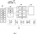
- Figure 1 shows a schematic functional block diagram of a vehicle 200.
- the vehicle 200 includes a sensing system 300 in charge of sensing data in a surrounding environment of the vehicle 200.
- the sensing system 300 may comprise multiple sensors, preferably of different types, such as radar sensor(s) 301, vision sensor(s) 302, ultrasonic sensor(s) 303, and/or lidar sensor(s) 304, etc.
- the vision sensors 302 may for example include one or more forward vision sensors 302a and one or more surround vision sensors 302b.
- the sensing system 300 may further include a semantic layer, or function, or module, 305 responsible for determining semantic data from data provided by the sensors 301-304.
- the semantic data includes semantic information about the environment around the vehicle 200, in other words information in a syntactic form. It may relate for example to a traffic sign, a traffic regulation, a disabled parking slot, etc...
- the semantic layer 305 may be implemented by software and hardware.
- the vehicle 200 may further include a perception stack or perception module 400.
- the perception stack 400 is responsible for determining environmental information related to the surrounding environment of the vehicle 200 using sensing data provided by the sensing system 300. It may implement algorithms and/or applications and/or functions for processing sensing data from the sensing system 300 to determine environmental information about the surrounding environment of the vehicle 200.
- the perception stack 400 may have a plurality of perception layers implementing respective algorithms and/or applications and/or functions for processing the sensing data to determine various information about the surrounding environment of the vehicle 200.
- the perception stack 400 may include:
- the perception stack 400 may be implemented by software and hardware.
- the perception layers may use algorithms such as machine learning algorithms.
- the vehicle 200 further includes a system 500 for tracking a parking area.
- the parking area can be a parking lot or a region, or part, of the parking lot.
- the parking area tracking system 500 has a function of determining a layout for a parking area.
- the system 500 may have another function of determining unoccupied or free parking slots, also termed as parking spaces, that are locations designated for parking, in a parking area.
- a layout of a parking area, or a parking area layout is a schematical representation of the parking area, for example in geometric shapes. It includes parking slot elements representing respective parking slots of the parking area. Each parking slot element may have a predetermined geometric shape, for example a U shape or a rectangular shape.
- the parking area layout may also include one or more aisle elements representing aisles, or traffic lanes, that are designated for moving within the parking lot or area.
- the parking area tracking system 500 may include a parking area layout tracker 501 and a parking slot tracker 502.
- the parking area layout tracker 501 is responsible for determining and updating over time, or tracking, a layout for a parking area, as described later in the method.
- a parking area may use different arrangements of parking slots in different parking areas or regions, respectively.
- a parking area may use perpendicular parking in a main parking area and, in supplement, parallel parking in a limited parking area.
- the parking area layout tracker 501 may determine a parking area layout for each parking area, or region, using a specific arrangement of parking slots.
- the parking slot elements tracker 502 is responsible for determining and updating over time, or tracking, the parking slot elements of the parking area layout, as described later in the method.
- the parking area tracking system 500 may further include, or be connected to, a database 550 of predefined parking lot layout models. Most of parking lots are designed, or arranged, in compliance with known parking arrangements. There are at least three main types, or categories, of parking: parallel, perpendicular and angle. In the parallel type, each parking slot is parallel to the direction in which a vehicle is approaching the parking slot. In the perpendicular type, each parking slot is perpendicular to the direction in which a vehicle is approaching the parking slot. In the angle type, each parking slot forms an angle A with the direction in which a vehicle is approaching the parking slot represented by an arrow in figure 1 . The angle type may have multiple variants depending on the angle. The most common angles used in the angle type parking areas are 30°, 45° and 60° for the acute angle A.
- Figure 1 shows five different predefined parking lot layout models of different types including one parallel type, one perpendicular type, and three angle types for the three respective acute angles A of 30°, 45° and 60°.
- the database 550 may further include, for each type of parking, multiple variants defined by different slot dimensions of the parking slot. Th slot dimensions include for example a slot width and a slot length.
- Each parking lot layout model may be associated with a parking slot template. In other words, each parking layout model may comprise an underlaying parking slot template.
- Each parking slot template may be characterized by a plurality of features including for example at least one of:
- the slot length may be a usable length of the parking slot, in other words the effective length that can be used by a vehicle to park.
- the parking area tracking system 500 may further include a semantic processing module 503 having the function of gathering semantic information about the surrounding environment of the vehicle 200 either from sensors 301-304, and/or from the semantic layer 305, and/or from the perception stack 400, and the function assigning special semantic information to parking slots and optionally to the layout. For example, if a special slot such as a parking slot for disabled person is sensed, the information "parking slot for disabled person" is assigned to the parking slot by the semantic processing module 503.
- the parking slot tracker 502 may be configured to reject the parking slot, based on the information "parking slot for disabled person", even if the slot is free, or unoccupied, as the vehicle 200 is not authorized to park in such a special slot.
- the parking area tracking system 500 may be implemented by software and hardware.
- the vehicle 200 may be an autonomous vehicle or at least partially automated vehicle.
- the vehicle 200 may further comprise an automatic parking system 600 configured to at least partially control the vehicle 200 to move in a parking area and/or perform a parking maneuver to park into a parking spot.
- the automatic parking system 600 may use information or data provided at the output of the parking area tracking system 500, as explained in the method described later.
- the automatic parking system 600 may be implemented by software and hardware.
- the perception stack 400, the parking area tracking system 500 and/or the automatic parking system 600 may be implemented on a same processor or controller, or on different processors or controllers.
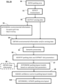
- a computer-implemented method of determining a parking layout for a parking area will now be described with reference to figures 2A-2B and 3 .
- a parking area may designate a parking lot or a region, or sub-area, of the parking lot.
- the sensing system 300 of the vehicle 200 collects information about a surrounding environment of the vehicle 200 with the sensors 301-304 in real time.
- the sensing system 300 monitors, senses in real time the surrounding environment or surrounding area of the vehicle with the sensors 301-304 of the vehicle 200.
- the step S1 may be performed while the vehicle 200 is moving in the parking area 700.
- the sensing system 300 outputs sensing data, in a step S2.
- the sensing data may include raw, or unprocessed, data and/or pre-processed data provided by the sensors 301-304.
- the sensing data may include semantic data about the surrounding environment of the vehicle 200, provided by the semantic layer 305.
- one or more sensors 301-304 may have the capacity to determine semantic information from sensing data.
- the sensing data contains information about the environment surrounding the vehicle 200.
- At least part of the sensing data may be received as input by the perception stack or perception module 400.
- the sensing data may be processed by the perception stack 400 to determine environmental information about the surrounding environment of the vehicle 200.
- the occupancy grid map generator 401 may generate an occupancy grid map related to the environment surrounding the vehicle 200.
- the occupancy grid map represents a map of an area surrounding the vehicle 200 as an evenly spaced field of binary random variables each representing the presence of an obstacle at that location in the area.
- the object tracker 402 may identify and track dynamic objects in the environment surrounding the vehicle 200.
- the environmental information is continuously determined, updated, in real time by the perception stack 400 from the sensing data continuously provided by the sensing system 300 in real time.
- the parking area tracking system 500 obtains, or receives, the environmental information about the surrounding environment of the vehicle 200, provided by the perception stack 400.
- the parking area tracking system 500 may directly receive at least part of the sensing data from the sensing system 300, and process the received sensing data to determine environmental information about the environment surrounding the vehicle 200.
- the semantic processing layer 503 of the parking area tracking system 500 may gather semantic information from the sensors 301-304, and/or the semantic layer 305, and/or the perception stack 400, and provide it to the parking area layout tracker 501 and to the parking slot tracker 502.
- the parking area layout tracker 501 may identify, or detect, parking slots in the environment around the vehicle 200 from the environmental information, obtained from the perception stack 400 and/or the semantic processing layer 503 and/or the sensing system 300.
- the tracker 501 may extract one or more parameters associated with identified parking slots from the environmental information, by data analysis.
- the parking area layout tracker 501 may identify or detect road surface markings delineating the parking spots and/or parked vehicles and/or occupied parking slots and/ unoccupied parking slots, based on the obtained environmental information.
- the extracted parameters associated with the identified parking slots may include, for each identified parking slot, at least part of the following features: a slot position relative to the vehicle 200, a slot width, a slot length, a parking orientation (e.g., parallel, perpendicular or angle) and/or a parking angle.
- a slot position relative to the vehicle 200 e.g., a slot width
- a slot length e.g., a slot width
- a parking orientation e.g., parallel, perpendicular or angle
- a parking angle e.g., parallel, perpendicular or angle
- the parking area layout tracker 501 determines one or more parking layout models for the parking area based on the extracted one or more parameters.
- each layout model includes an underlaying parking slot template.
- the one or more extracted slot parameters associated with the one or more parking slots identified in the step S6 may be used as filter or selection criteria to retrieve one or more parking layout models from the database 550.
- a selection of one or more parking layout models in the database 550 may thus be performed by only selecting the parking layout model(s) whose underlaying parking slot template matches at least partially the extracted parameter(s).
- the parking layout models from the database 550, whose parking slot templates do not match any parameter extracted from the environmental information, may be excluded from the selection.
- the parking area layout tracker 501 may obtain map information related to a current location of the vehicle 200.
- the map information may be used as an additional filter or selection criteria to select one or more parking layout models in the database 550, in the step S7.
- the map information may be received from an online mapping platform to which the vehicle 200 is connected through a mobile communication network, and/or from a mapping application installed on the vehicle 200.
- determining one or more parking layout models for the parking area may be further based on the semantic information about the surrounding environment of the vehicle.
- the parking area layout tracker 501 assigns a confidence score to each of the parking layout models determined in the step S7.
- the confidence score assigned to each parking layout model indicates how the corresponding underlaying parking slot template matches the one or more extracted parameters of the parking slots identified from the environmental information.
- the confidence score assigned to each parking layout model quantifies a correspondence, a matching, between the parking slot template of this parking layout model and the one or more extracted slot parameter.
- the computation of the confidence score can be executed by a computation algorithm for example based on an algorithm known as "intersection over union" that gives similarity values or coefficients from 0 to 1 and measures similarity between two sample sets or objects for object detection in images.
- the computation algorithm may measure similarity between the parking slot template and the identified parking slot in terms of orientation and/or dimensions. For each parking layout model, a similarity coefficient may be computed for each identified or detected parking slot. Then, an overall score can be calculated by combining the scores obtained for a plurality of identified parking slots, which gives the confidence score assigned to this parking layout model.
- the method further comprises a step S10, performed by the parking layout tracker 501, of selecting and updating over time a layout model for the parking area, based on the confidence scores assigned to the one or more parking layout models.
- the parking layout tracker 501 selects the layout model of the parking area having the highest confidence score as a current layout model.
- the selected layout model is updated over time, by the parking layout tracker 501, based on the confidence scores assigned to the layout models generated from sensing data collected while the vehicle is moving.
- the current parking layout model is used by the parking layout tracker 501 to build, or determine, the parking area layout.
- all the features of the parking area layout may be derived from the current parking layout model.
- some features of the parking area layout may be derived from the extracted parameters of the identified parking slots.
- the parking area layout may be based on a basic parking layout model, like one of the five models shown in figure 1 , but have a slot width and a slot length determined from the extracted parameters.
- the step S10 may be continuously executed in real time.
- the steps S1 to S10 are performed in real time, continuously. While the vehicle 200 is moving in the parking area 700, its sensing system 300 continuously collects information about the surrounding environment of the vehicle 200. In this way, the parking area tracking system 500 gets more and more environmental information about the surrounding environment of the vehicle 200 over time. Over time, more and more parking slots can be identified in the step S6, and the extracted slot parameters can become more and more precise. In the step S9, the confidence scores assigned to the one or more parking layout models are updated over time and are more and more reliable. This allows the parking area layout tracker 501 to converge over time to the correct parking layout model.
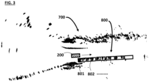
- Figure 3 represents an example of a parking area layout 800 including a plurality of parking slot elements 801, 802, ..., representing parking slots of the parking area 700.
- the parking area layout 800 is superimposed on an occupancy grid map.
- the parking slot elements may include:
- the prediction, or extrapolation, of the second parking slot elements may use environmental information and/or map information, for example a road curve, and/or the presence of building(s) in the area, and/or the presence of a wall at a certain distance to the vehicle 200, etc., to adjust the prediction or extrapolation.
- environmental information and/or map information for example a road curve, and/or the presence of building(s) in the area, and/or the presence of a wall at a certain distance to the vehicle 200, etc.
- the step S10 may include :
- Predicting the second parking slot elements may include adding or placing parking slot elements outside of a sensing area covered by the sensing system 300 of the vehicle 200, in the parking area layout 800.
- the determined parking area layout may be used to control one or more functions of the vehicle 200.
- the determined parking area layout may be used to control a driving trajectory of the vehicle 200 and/or an Advanced Driver Assistance System, or ADAS, control function.
- the parking area layout 800 may be used by the automatic parking system 600, and/or by an automated driving system, of the vehicle 200 to control the vehicle 200 to move within the parking area 700 in an automated manner or partially automated manner.
- the method may include a step of controlling one or more functions of the vehicle 200 moving in the parking area 700 in an automated or partially automated manner, by using the parking area layout 800. This allows to facilitate and secure the action of driving the vehicle 200 in the parking area 700.
- the method may further include a step S11 of assigning an occupancy status score to each of the plurality of parking slot elements 801, 802, ... of the parking area layout 800, and updating the occupancy status scores, based on the obtained environmental information.
- the step S11 may be continuously performed by the parking slot tracker 502, in real time.
- the occupancy status score of each parking slot element 801, 802, ... of the parking area layout 800 indicates a probability of occupancy of the corresponding parking slot of the parking area 700.
- a score indicating an unoccupied status may be assigned by default to each of the parking slot elements 801, 802, ... of the parking area layout 800, unless the obtained environmental information provides an occupancy indication, or evidence, for the corresponding parking slot.
- the occupancy indication can be the indication that a vehicle is parked in the parking slot, or an object is detected in the parking slot, or a part of a vehicle is detected in the parking slot.
- the occupancy grid map produced by the generator 401 may also give evidence about free, or unoccupied, space in a certain area.
- the parking slot tracker 502 may rely on such information to determine if the area can be considered as unoccupied, or unknown, or occupied, and assign occupancy status scores to the parking slot elements.
- the parking slot tracker 502 may also use the output of the semantic processing module 503 to assign special information to parking slot elements of the parking layout 800, for example the information that the parking slot is for a disabled person, in an optional step S12.
- the parking slot tracker 502 may optionally perform a semantic classification of the parking slot elements 801, 802, ... of the parking area layout 800, into different categories, based on the scores assigned to the parking slot elements and optionally special information received from the semantic processing module 503.
- the different categories may include at least part of the following categories : unoccupied parking slot, occupied parking slot, unknown status, and/or special parking slot, for example parking slot for disabled person.
- the step S11, and the optional steps S12, S13 are continuously performed in real time, based on the environmental information continuously obtained.
- the occupancy status scores of the parking slot elements 801, 802, ... of the parking area layout 800 are continuously updated in real time, based on the environmental information continuously obtained.
- the automatic parking system 600 may have been initiated by a user, for example when the vehicle 200 enters the parking area 700.
- the automatic parking system 600 may control the vehicle 200 to move in the parking area to search for an unoccupied parking slot suitable for parking, in an automated or at least partially automated manner, based on the parking area layout 800.
- the method may further include a step S15, performed by the parking slot tracker 502, of identifying at least one unoccupied parking slot suitable for parking in the parking area 700, based on the occupancy status score assigned to each of the plurality of parking slot elements of the parking area layout 800 and/or based on the result of the classification of the parking slot elements performed in the step S13. This can be performed by comparing the occupancy status score of each parking slot element with a predetermined threshold, and/or based on the parking slot categories resulting from the classification.
- the automatic parking system 600 may set or plan a parking maneuver to park the vehicle 200 in the unoccupied parking slot. If a plurality of unoccupied parking slots suitable for parking has been detected, the automatic parking system 600 may select one of them, for example the unoccupied parking slot closest to the vehicle 200.
- the automatic parking system 600 may control the vehicle 200 to execute the parking maneuver set or planned in the step S16, to park the vehicle 200 in the unoccupied parking slot, in an automated or partially automated manner.
- the parking maneuver may at least include a movement of the vehicle 200 consisting in approaching the unoccupied parking slot, used as a target parking slot. While the vehicle 200 is approaching this target parking slot, the parking area layout and the occupancy status scores of the parking slot elements are updated continuously, in real time. It may happen that the target parking slot for the parking maneuver be finally identified as an occupied parking slot. In that case, the automatic parking system 600 repeats the steps S13 and S15 to park the vehicle 200 in another parking slot.
- the parking area layout may be displayed on a display apparatus of the vehicle 200. It may be superimposed on a map representing the environment of the vehicle 200.
- the parking area layout displayed on the display apparatus may be used by a driver to facilitate the maneuvers in the parking area 700.
- the method may further include a step of generating a map based on the parking area layout.
- This map may be displayed on a display apparatus of the vehicle.
- the parking slot elements of the parking area layout may be classified into three categories based on their occupancy status scores: unoccupied, occupied, unknown.
- the three categories may be represented by different colors on the display apparatus.
- the present disclosure also concerns:
Landscapes
- Engineering & Computer Science (AREA)
- Physics & Mathematics (AREA)
- General Physics & Mathematics (AREA)
- Radar, Positioning & Navigation (AREA)
- Remote Sensing (AREA)
- Automation & Control Theory (AREA)
- Transportation (AREA)
- Mechanical Engineering (AREA)
- Analytical Chemistry (AREA)
- Chemical & Material Sciences (AREA)
- Human Computer Interaction (AREA)
- Theoretical Computer Science (AREA)
- Multimedia (AREA)
- Business, Economics & Management (AREA)
- Health & Medical Sciences (AREA)
- Artificial Intelligence (AREA)
- Evolutionary Computation (AREA)
- Game Theory and Decision Science (AREA)
- Medical Informatics (AREA)
- Aviation & Aerospace Engineering (AREA)
- Traffic Control Systems (AREA)
- Control Of Driving Devices And Active Controlling Of Vehicle (AREA)
Abstract
Description
- The present disclosure relates to a computer-implemented method of determining a layout for a parking area. The parking area may be a parking lot or a region of a parking lot. Such a method can be used for example by a vehicle to determine a parking area layout and control the vehicle to move within the parking area based on the parking area layout, in an automated or partially automated manner.
- In the automotive field, parking systems have been developed to control the vehicle in executing parking maneuvers in an automated manner or partially automated manner. The parking systems rely on multiple sensors, e.g. vision sensors, Lidar sensors, radar sensors, Global Navigation Satellite System (GNSS), and a perception stack to collect information about a surrounding environment of the vehicle, and detect a free or unoccupied parking slot, also termed as parking space. Once a free parking slot has been detected and confirmed, the parking system starts planning a parking maneuver and then controls at least partially the vehicle to execute the planned parking maneuver.
- Before planning the parking maneuver, the parking system accumulates evidences of occupancy from the perception stack, post process the evidences of occupancy to detect gaps between occupied spaces and classify detected gaps as parking slots. After detection of a parking slot, the slot occupancy status is tracked and, if the slot is unoccupied, a path is planned to perform the parking maneuver to park the vehicle in the unoccupied parking slot.
- The existing parking systems are effective in controlling the vehicle to perform automated or partially automated parking maneuvers. However, they have a high latency. The algorithms implemented for planning the parking maneuver have to wait for a confirmation that a detected gap is unoccupied and can fit the vehicle, which can generally be performed only after passing it by. As a result, the overall execution time for a parking maneuver controlled by the parking system is significantly increased.
- The present disclosure allows to improve the situation. In particular, there is a need for facilitating maneuvers for a vehicle in a parking area.
- The present disclosure concerns a computer-implemented method of determining a layout for a parking area, comprising the following steps:
- determining environmental information about a surrounding environment of a vehicle from sensing data provided by a sensing system of said vehicle, while the vehicle is moving in the parking area;
- extracting one or more parameters associated with parking slots identified from the environmental information;
- determining one or more layout models for the parking area based at least on the extracted one or more parameters, each layout model comprising an underlaying parking slot template;
- assigning to each of the determined layout models a confidence score, indicating how the respective underlaying parking slot template matches the one or more parameters associated with the parking slots identified from the environmental information; and
- selecting the layout model of the parking area having the highest confidence score as a current layout model used to determine the parking area layout; wherein, the selected layout model is updated over time based on the confidence scores assigned to the layout models generated from sensing data collected while the vehicle is moving.
- The determined parking area layout can be used to control one or more functions of the vehicle. For example, the determined parking area layout can be used by a path planning module of the vehicle, to better plan a trajectory within the parking area for the vehicle. The vehicle can be controlled to move along the planned trajectory in an automated or at least partially automated manner. This allows faster, smoother and more secure maneuvers of the vehicle in the parking area.
- Advantageously, the determined parking area layout is used to control a driving trajectory of the vehicle and/or an Advanced Driver Assistance Systems (ADAS) control function.
- For example, the method may also include a step of controlling the vehicle to move along a driving trajectory planned using the determined parking area layout, in an automated or partially automated manner.
- In an embodiment, the method may further include a step of assigning an occupancy status score to each of a plurality of parking slot elements of the layout of the parking area, indicating a probability of occupancy of said parking slot, and updating the occupancy status scores based on the environmental information.
- In an embodiment, a score indicating an unoccupied status may be assigned by default to each of the parking slot elements of the layout of the parking area, unless the environmental information provides an occupancy indication for said parking slot element.
- Advantageously, the method may further include a step of identifying an unoccupied parking slot based on the occupancy status score assigned to each of the plurality of parking slot elements, and a step of determining a parking maneuver to park the vehicle in the identified unoccupied parking slot. The method may also include a step of controlling the vehicle to execute the set parking maneuver in an automated or partially automated manner.
- The identification of an unoccupied parking slot by using the parking area layout built based on a layout model allows to reduce the parking maneuver latency. In other words, the execution time of a parking maneuver executed by the vehicle in an automated or partially automated manner is significantly decreased. The detection of an unoccupied parking slot can be performed earlier than in the prior art, since it is no longer necessary to pass by the unoccupied parking slot to start a parking maneuver. Furthermore, the parking maneuver can be significantly simplified by planning a smoother and simpler trajectory for the vehicle.
- The present method has another advantage that it does not require specific sensors and/or specific perception means.
- In an embodiment, the one or more parameters associated with an identified parking slot, extracted from the environmental information, includes at least one of the following elements:
- a position of the identified parking slot relative to the vehicle;
- one or more dimensions of the identified parking slot;
- an orientation of the identified parking slot.
- In an embodiment, updating over time the layout of the parking area includes generating over time first parking slot elements representing parking slots already identified from the environmental information, and predicting second parking slot elements corresponding to parking slots foreseen based on the parking slots already identified from the environmental information and the current layout model.
- The parking area layout can extend beyond the parking slots that have already been identified or detected, by addition of parking slots predicted, or extrapolated, based on the layout model and the parking slots already identified. This allows an earlier estimation of parking slots location, which can reduce significantly the complexity of the parking maneuver by planning a simpler trajectory. It is not guaranteed that a predicted or foreseen parking slot exists and is unoccupied. But, the parking slot will be confirmed or not confirmed later once more environmental information has been obtained.
- Advantageously, predicting the second parking slot elements includes placing, or adding, parking slot elements outside of a sensing area covered by the sensing system of the vehicle within the parking area layout.
- The present disclosure also concerns a
- a computer program comprising instructions which, when the program is executed by a computer, cause the computer to carry out the method previously defined;
- a computing system comprising means adapted to execute the steps of the method;
- a vehicle including the computing system.
- Other features, purposes and advantages of the disclosure will become more explicit by means of reading the detailed statement of the non-restrictive embodiments made with reference to the accompanying drawings.
-
Figure 1 schematically represents a vehicle including a computing system of determining a parking area layout, according to an embodiment. -
Figure 2A-2B shows a flowchart of a method of determining a layout for a parking area, according to an embodiment. -
Figure 3 illustrates an example of a parking area layout determined using the method offigure 2 . -
Figure 1 shows a schematic functional block diagram of avehicle 200. - The
vehicle 200 includes asensing system 300 in charge of sensing data in a surrounding environment of thevehicle 200. Thesensing system 300 may comprise multiple sensors, preferably of different types, such as radar sensor(s) 301, vision sensor(s) 302, ultrasonic sensor(s) 303, and/or lidar sensor(s) 304, etc. The vision sensors 302 may for example include one or moreforward vision sensors 302a and one or moresurround vision sensors 302b. - Optionally, the
sensing system 300 may further include a semantic layer, or function, or module, 305 responsible for determining semantic data from data provided by the sensors 301-304. The semantic data includes semantic information about the environment around thevehicle 200, in other words information in a syntactic form. It may relate for example to a traffic sign, a traffic regulation, a disabled parking slot, etc... Thesemantic layer 305 may be implemented by software and hardware. - The
vehicle 200 may further include a perception stack orperception module 400. Theperception stack 400 is responsible for determining environmental information related to the surrounding environment of thevehicle 200 using sensing data provided by thesensing system 300. It may implement algorithms and/or applications and/or functions for processing sensing data from thesensing system 300 to determine environmental information about the surrounding environment of thevehicle 200. Theperception stack 400 may have a plurality of perception layers implementing respective algorithms and/or applications and/or functions for processing the sensing data to determine various information about the surrounding environment of thevehicle 200. For example, theperception stack 400 may include: - an occupancy
grid map generator 401 for generating an occupancy grid map of the surrounding environment of thevehicle 200 from the sensing data; and - an
object tracker 402 for identifying and tracking dynamic objects in the surrounding environment of thevehicle 200 from the sensing data. - The
perception stack 400 may be implemented by software and hardware. The perception layers may use algorithms such as machine learning algorithms. - In the present disclosure, the
vehicle 200 further includes asystem 500 for tracking a parking area. The parking area can be a parking lot or a region, or part, of the parking lot. The parkingarea tracking system 500 has a function of determining a layout for a parking area. Optionally, thesystem 500 may have another function of determining unoccupied or free parking slots, also termed as parking spaces, that are locations designated for parking, in a parking area. - A layout of a parking area, or a parking area layout, is a schematical representation of the parking area, for example in geometric shapes. It includes parking slot elements representing respective parking slots of the parking area. Each parking slot element may have a predetermined geometric shape, for example a U shape or a rectangular shape. The parking area layout may also include one or more aisle elements representing aisles, or traffic lanes, that are designated for moving within the parking lot or area.
- The parking
area tracking system 500 may include a parkingarea layout tracker 501 and aparking slot tracker 502. - The parking
area layout tracker 501 is responsible for determining and updating over time, or tracking, a layout for a parking area, as described later in the method. - It should be noted that a parking area may use different arrangements of parking slots in different parking areas or regions, respectively. For example, a parking area may use perpendicular parking in a main parking area and, in supplement, parallel parking in a limited parking area. The parking
area layout tracker 501 may determine a parking area layout for each parking area, or region, using a specific arrangement of parking slots. - The parking
slot elements tracker 502 is responsible for determining and updating over time, or tracking, the parking slot elements of the parking area layout, as described later in the method. - The parking
area tracking system 500 may further include, or be connected to, adatabase 550 of predefined parking lot layout models. Most of parking lots are designed, or arranged, in compliance with known parking arrangements. There are at least three main types, or categories, of parking: parallel, perpendicular and angle. In the parallel type, each parking slot is parallel to the direction in which a vehicle is approaching the parking slot. In the perpendicular type, each parking slot is perpendicular to the direction in which a vehicle is approaching the parking slot. In the angle type, each parking slot forms an angle A with the direction in which a vehicle is approaching the parking slot represented by an arrow infigure 1 . The angle type may have multiple variants depending on the angle. The most common angles used in the angle type parking areas are 30°, 45° and 60° for the acute angle A. -
Figure 1 shows five different predefined parking lot layout models of different types including one parallel type, one perpendicular type, and three angle types for the three respective acute angles A of 30°, 45° and 60°. Thedatabase 550 may further include, for each type of parking, multiple variants defined by different slot dimensions of the parking slot. Th slot dimensions include for example a slot width and a slot length. Each parking lot layout model may be associated with a parking slot template. In other words, each parking layout model may comprise an underlaying parking slot template. Each parking slot template may be characterized by a plurality of features including for example at least one of: - an angle of parking (e.g., 0°, 30°, 45°, 60° or 90°);
- a slot width;
- a slot length.
- The slot length may be a usable length of the parking slot, in other words the effective length that can be used by a vehicle to park.
- Optionally, the parking
area tracking system 500 may further include asemantic processing module 503 having the function of gathering semantic information about the surrounding environment of thevehicle 200 either from sensors 301-304, and/or from thesemantic layer 305, and/or from theperception stack 400, and the function assigning special semantic information to parking slots and optionally to the layout. For example, if a special slot such as a parking slot for disabled person is sensed, the information "parking slot for disabled person" is assigned to the parking slot by thesemantic processing module 503. Theparking slot tracker 502 may be configured to reject the parking slot, based on the information "parking slot for disabled person", even if the slot is free, or unoccupied, as thevehicle 200 is not authorized to park in such a special slot. - The parking
area tracking system 500 may be implemented by software and hardware. - The
vehicle 200 may be an autonomous vehicle or at least partially automated vehicle. - In an embodiment, the
vehicle 200 may further comprise anautomatic parking system 600 configured to at least partially control thevehicle 200 to move in a parking area and/or perform a parking maneuver to park into a parking spot. Theautomatic parking system 600 may use information or data provided at the output of the parkingarea tracking system 500, as explained in the method described later. Theautomatic parking system 600 may be implemented by software and hardware. - The
perception stack 400, the parkingarea tracking system 500 and/or theautomatic parking system 600 may be implemented on a same processor or controller, or on different processors or controllers. - A computer-implemented method of determining a parking layout for a parking area, according to an embodiment, will now be described with reference to
figures 2A-2B and3 . A parking area may designate a parking lot or a region, or sub-area, of the parking lot. - Let's consider that the
vehicle 200 enters aparking area 700, in a step S0, and is moving in theparking area 700. - In a step S1 of detection of the environment, the
sensing system 300 of thevehicle 200 collects information about a surrounding environment of thevehicle 200 with the sensors 301-304 in real time. In other words, thesensing system 300 monitors, senses in real time the surrounding environment or surrounding area of the vehicle with the sensors 301-304 of thevehicle 200. The step S1 may be performed while thevehicle 200 is moving in theparking area 700. - The
sensing system 300 outputs sensing data, in a step S2. The sensing data may include raw, or unprocessed, data and/or pre-processed data provided by the sensors 301-304. Optionally, the sensing data may include semantic data about the surrounding environment of thevehicle 200, provided by thesemantic layer 305. Optionally, one or more sensors 301-304 may have the capacity to determine semantic information from sensing data. The sensing data contains information about the environment surrounding thevehicle 200. - At least part of the sensing data may be received as input by the perception stack or
perception module 400. In a step S3, the sensing data may be processed by theperception stack 400 to determine environmental information about the surrounding environment of thevehicle 200. - In an embodiment, in the step S3, the occupancy
grid map generator 401 may generate an occupancy grid map related to the environment surrounding thevehicle 200. The occupancy grid map represents a map of an area surrounding thevehicle 200 as an evenly spaced field of binary random variables each representing the presence of an obstacle at that location in the area. - In the step S3, the
object tracker 402 may identify and track dynamic objects in the environment surrounding thevehicle 200. - The environmental information is continuously determined, updated, in real time by the perception stack 400 from the sensing data continuously provided by the
sensing system 300 in real time. - In a reception step S4, the parking
area tracking system 500 obtains, or receives, the environmental information about the surrounding environment of thevehicle 200, provided by theperception stack 400. - Additionally, or alternatively, in the reception step S4, the parking
area tracking system 500 may directly receive at least part of the sensing data from thesensing system 300, and process the received sensing data to determine environmental information about the environment surrounding thevehicle 200. - In an embodiment, in a step S5, the
semantic processing layer 503 of the parkingarea tracking system 500 may gather semantic information from the sensors 301-304, and/or thesemantic layer 305, and/or theperception stack 400, and provide it to the parkingarea layout tracker 501 and to theparking slot tracker 502. - In a step S6, the parking
area layout tracker 501 may identify, or detect, parking slots in the environment around thevehicle 200 from the environmental information, obtained from theperception stack 400 and/or thesemantic processing layer 503 and/or thesensing system 300. Thetracker 501 may extract one or more parameters associated with identified parking slots from the environmental information, by data analysis. For example, the parkingarea layout tracker 501 may identify or detect road surface markings delineating the parking spots and/or parked vehicles and/or occupied parking slots and/ unoccupied parking slots, based on the obtained environmental information. The extracted parameters associated with the identified parking slots may include, for each identified parking slot, at least part of the following features: a slot position relative to thevehicle 200, a slot width, a slot length, a parking orientation (e.g., parallel, perpendicular or angle) and/or a parking angle. Some extracted parameters might not be very accurate, and be quantified by a range of values. - Then, in a step S7, the parking
area layout tracker 501 determines one or more parking layout models for the parking area based on the extracted one or more parameters. As previously indicated, in thedatabase 550, each layout model includes an underlaying parking slot template. The one or more extracted slot parameters associated with the one or more parking slots identified in the step S6 may be used as filter or selection criteria to retrieve one or more parking layout models from thedatabase 550. A selection of one or more parking layout models in thedatabase 550 may thus be performed by only selecting the parking layout model(s) whose underlaying parking slot template matches at least partially the extracted parameter(s). The parking layout models from thedatabase 550, whose parking slot templates do not match any parameter extracted from the environmental information, may be excluded from the selection. - Optionally, in a step S8, the parking
area layout tracker 501 may obtain map information related to a current location of thevehicle 200. The map information may be used as an additional filter or selection criteria to select one or more parking layout models in thedatabase 550, in the step S7. The map information may be received from an online mapping platform to which thevehicle 200 is connected through a mobile communication network, and/or from a mapping application installed on thevehicle 200. - Optionally, determining one or more parking layout models for the parking area may be further based on the semantic information about the surrounding environment of the vehicle.
- In a step S9, the parking
area layout tracker 501 assigns a confidence score to each of the parking layout models determined in the step S7. The confidence score assigned to each parking layout model indicates how the corresponding underlaying parking slot template matches the one or more extracted parameters of the parking slots identified from the environmental information. In other words, the confidence score assigned to each parking layout model quantifies a correspondence, a matching, between the parking slot template of this parking layout model and the one or more extracted slot parameter. The computation of the confidence score can be executed by a computation algorithm for example based on an algorithm known as "intersection over union" that gives similarity values or coefficients from 0 to 1 and measures similarity between two sample sets or objects for object detection in images. The computation algorithm may measure similarity between the parking slot template and the identified parking slot in terms of orientation and/or dimensions. For each parking layout model, a similarity coefficient may be computed for each identified or detected parking slot. Then, an overall score can be calculated by combining the scores obtained for a plurality of identified parking slots, which gives the confidence score assigned to this parking layout model. - The method further comprises a step S10, performed by the
parking layout tracker 501, of selecting and updating over time a layout model for the parking area, based on the confidence scores assigned to the one or more parking layout models. In the step S10, theparking layout tracker 501 selects the layout model of the parking area having the highest confidence score as a current layout model. The selected layout model is updated over time, by theparking layout tracker 501, based on the confidence scores assigned to the layout models generated from sensing data collected while the vehicle is moving. - In the step S10, the current parking layout model is used by the
parking layout tracker 501 to build, or determine, the parking area layout. In some embodiments, all the features of the parking area layout may be derived from the current parking layout model. In other embodiment, some features of the parking area layout may be derived from the extracted parameters of the identified parking slots. For example, the parking area layout may be based on a basic parking layout model, like one of the five models shown infigure 1 , but have a slot width and a slot length determined from the extracted parameters. - The step S10 may be continuously executed in real time.
- The steps S1 to S10 are performed in real time, continuously. While the
vehicle 200 is moving in theparking area 700, itssensing system 300 continuously collects information about the surrounding environment of thevehicle 200. In this way, the parkingarea tracking system 500 gets more and more environmental information about the surrounding environment of thevehicle 200 over time. Over time, more and more parking slots can be identified in the step S6, and the extracted slot parameters can become more and more precise. In the step S9, the confidence scores assigned to the one or more parking layout models are updated over time and are more and more reliable. This allows the parkingarea layout tracker 501 to converge over time to the correct parking layout model. -
Figure 3 represents an example of aparking area layout 800 including a plurality ofparking slot elements parking area 700. Infigure 3 , theparking area layout 800 is superimposed on an occupancy grid map. In an embodiment, the parking slot elements may include: - first parking slot elements, representing parking slots identified by the parking
area layout tracker 501 from the obtained environmental information, and - second parking slot elements, corresponding to parking slots foreseen, or predicted, or extrapolated, by the parking
area layout tracker 501, based on the parking slots already identified from the obtained environmental information and the current parking layout model. - The prediction, or extrapolation, of the second parking slot elements may use environmental information and/or map information, for example a road curve, and/or the presence of building(s) in the area, and/or the presence of a wall at a certain distance to the
vehicle 200, etc., to adjust the prediction or extrapolation. - Thus, the step S10 may include :
- generating the first parking slot elements representing the parking slots already identified from the obtained environmental information;
- predicting the second parking slot elements foreseen or extrapolated based on the parking slots already identified from the obtained environmental information and the current parking layout model.
- Predicting the second parking slot elements may include adding or placing parking slot elements outside of a sensing area covered by the
sensing system 300 of thevehicle 200, in theparking area layout 800. - The determined parking area layout may be used to control one or more functions of the
vehicle 200. In some embodiments, the determined parking area layout may be used to control a driving trajectory of thevehicle 200 and/or an Advanced Driver Assistance System, or ADAS, control function. For example, theparking area layout 800 may be used by theautomatic parking system 600, and/or by an automated driving system, of thevehicle 200 to control thevehicle 200 to move within theparking area 700 in an automated manner or partially automated manner. Thus, the method may include a step of controlling one or more functions of thevehicle 200 moving in theparking area 700 in an automated or partially automated manner, by using theparking area layout 800. This allows to facilitate and secure the action of driving thevehicle 200 in theparking area 700. - In an embodiment, the method may further include a step S11 of assigning an occupancy status score to each of the plurality of
parking slot elements parking area layout 800, and updating the occupancy status scores, based on the obtained environmental information. The step S11 may be continuously performed by theparking slot tracker 502, in real time. The occupancy status score of eachparking slot element parking area layout 800 indicates a probability of occupancy of the corresponding parking slot of theparking area 700. - In a particular embodiment, a score indicating an unoccupied status may be assigned by default to each of the
parking slot elements parking area layout 800, unless the obtained environmental information provides an occupancy indication, or evidence, for the corresponding parking slot. The occupancy indication can be the indication that a vehicle is parked in the parking slot, or an object is detected in the parking slot, or a part of a vehicle is detected in the parking slot. - The occupancy grid map produced by the
generator 401 may also give evidence about free, or unoccupied, space in a certain area. Theparking slot tracker 502 may rely on such information to determine if the area can be considered as unoccupied, or unknown, or occupied, and assign occupancy status scores to the parking slot elements. - The
parking slot tracker 502 may also use the output of thesemantic processing module 503 to assign special information to parking slot elements of theparking layout 800, for example the information that the parking slot is for a disabled person, in an optional step S12. - In a step S13, the
parking slot tracker 502 may optionally perform a semantic classification of theparking slot elements parking area layout 800, into different categories, based on the scores assigned to the parking slot elements and optionally special information received from thesemantic processing module 503. The different categories may include at least part of the following categories : unoccupied parking slot, occupied parking slot, unknown status, and/or special parking slot, for example parking slot for disabled person. - The step S11, and the optional steps S12, S13 are continuously performed in real time, based on the environmental information continuously obtained. Thus, the occupancy status scores of the
parking slot elements parking area layout 800 are continuously updated in real time, based on the environmental information continuously obtained. - The
automatic parking system 600 may have been initiated by a user, for example when thevehicle 200 enters theparking area 700. - In an optional step S14, the
automatic parking system 600 may control thevehicle 200 to move in the parking area to search for an unoccupied parking slot suitable for parking, in an automated or at least partially automated manner, based on theparking area layout 800. - The method may further include a step S15, performed by the
parking slot tracker 502, of identifying at least one unoccupied parking slot suitable for parking in theparking area 700, based on the occupancy status score assigned to each of the plurality of parking slot elements of theparking area layout 800 and/or based on the result of the classification of the parking slot elements performed in the step S13. This can be performed by comparing the occupancy status score of each parking slot element with a predetermined threshold, and/or based on the parking slot categories resulting from the classification. - In a step S16, after identification or detection of at least one unoccupied parking slot suitable for parking in the
parking area 700 in the step S13, theautomatic parking system 600 may set or plan a parking maneuver to park thevehicle 200 in the unoccupied parking slot. If a plurality of unoccupied parking slots suitable for parking has been detected, theautomatic parking system 600 may select one of them, for example the unoccupied parking slot closest to thevehicle 200. - Then, in a step S17, the
automatic parking system 600 may control thevehicle 200 to execute the parking maneuver set or planned in the step S16, to park thevehicle 200 in the unoccupied parking slot, in an automated or partially automated manner. The parking maneuver may at least include a movement of thevehicle 200 consisting in approaching the unoccupied parking slot, used as a target parking slot. While thevehicle 200 is approaching this target parking slot, the parking area layout and the occupancy status scores of the parking slot elements are updated continuously, in real time. It may happen that the target parking slot for the parking maneuver be finally identified as an occupied parking slot. In that case, theautomatic parking system 600 repeats the steps S13 and S15 to park thevehicle 200 in another parking slot. - The parking area layout may be displayed on a display apparatus of the
vehicle 200. It may be superimposed on a map representing the environment of thevehicle 200. The parking area layout displayed on the display apparatus may be used by a driver to facilitate the maneuvers in theparking area 700. - The method may further include a step of generating a map based on the parking area layout. This map may be displayed on a display apparatus of the vehicle. The parking slot elements of the parking area layout may be classified into three categories based on their occupancy status scores: unoccupied, occupied, unknown. The three categories may be represented by different colors on the display apparatus.
- The present disclosure also concerns:
- a computer program comprising instructions which, when the program is executed by a computer, cause the computer to carry out the method previously defined;
- a computer-readable data medium having stored thereon the computer program above defined;
- a computing system having means adapted to execute the steps of the method previously described;
- a vehicle including the above-defined computing system.
Claims (15)
- A computer-implemented method of determining a layout for a parking area (700), comprising the following steps:- determining (S3, S4, S5) environmental information about a surrounding environment of a vehicle (200) from sensing data provided by a sensing system of said vehicle, while the vehicle (200) is moving in the parking area (700);determining a layout (800) for the parking area (700) by performing the steps of:- extracting (S6) one or more parameters associated with parking slots identified from the environmental information;- determining (S7) one or more layout models for the parking area based at least on the extracted one or more parameters, each layout model comprising an underlaying parking slot template;- assigning (S9) to each of the determined layout models a confidence score, indicating how the respective underlaying parking slot template matches the one or more parameters associated with the parking slots identified from the environmental information; and- selecting (S10) the layout model of the parking area having the highest confidence score as a current layout model used to determine the parking area layout;wherein, the selected layout model is updated over time based on the confidence scores assigned to the layout models generated from sensing data collected while the vehicle is moving.
- The computer-implemented method according to claim 1, wherein the determined parking area layout is used to control one or more functions of the vehicle.
- The computer-implemented method according to claim 1 or 2, wherein the determined parking area layout is used to control a driving trajectory of the vehicle and/or an Advanced Driver Assistance System (ADAS) control function
- The computer-implemented method according to any one of the preceding claims, wherein, the method further includes a step (S11) of assigning an occupancy status score to each of a plurality of parking slot elements (801, 802, ...) of the layout (800) of the parking area (700), indicating a probability of occupancy of said parking slot, and updating the occupancy status scores based on the environmental information.
- The computer-implemented method according to claim 4, wherein a score indicating an unoccupied status is assigned by default to each of the parking slot elements of the layout of the parking area, unless the environmental information provides an occupancy indication for said parking slot element.
- The computer-implemented method according to any one of the preceding claims , further including a step (S13) of identifying an unoccupied parking slot based on the occupancy status score assigned to each of the plurality of parking slot elements, and a step (S15) of determining a parking maneuver to park the vehicle (200) in the identified unoccupied parking slot.
- The computer-implemented method according to any of claims 1 to 6, wherein the one or more parameters associated with an identified parking slot, extracted from the environmental information, includes at least one of the following elements:a position of the identified parking slot relative to the vehicle;one or more dimensions of the identified parking slot;an orientation of the identified parking slot.
- The computer-implemented method according to any of claims 1 to 7, wherein updating (S10) over time the layout (800) of the parking area (700) includes generating over time first parking slot elements representing parking slots already identified from the environmental information, and predicting second parking slot elements corresponding to parking slots foreseen based on the parking slots already identified from the environmental information and the current layout model.
- The computer-implement method according to claim 8, wherein predicting the second parking slot elements includes placing parking slot elements outside of a sensing area covered by the sensing system of the vehicle within the parking area layout.
- The computer-implemented method according to any of claims 1 to 9, wherein the step (S7) of determining one or more layout models includes retrieving the one or more layout models from a database (503) storing a plurality of predefined layout models.
- The computer-implemented method according to any of claims 1 to 10, wherein the step of determining an environmental information related to the surrounding environment of the vehicle from the sensing data provided by the sensing system of the vehicle includes at least one of:. generating an occupancy grid map of the environment of the vehicle;. performing object tracking in the environment of the vehicle;. obtaining semantic information on the environment of the vehicle;. performing a semantic classification of parking slots into different categories.
- The computer-implemented method according to claim 11, wherein determining (S7) one or more layout models for the parking area is further based on the semantic information about the surrounding environment of the vehicle (200).
- A computer program comprising instructions which, when the program is executed by a computer, cause the computer to carry out the method of any of claims 1 to 12.
- A computing system, comprising means adapted to execute the steps of the method of any of claims 1 to 12.
- A vehicle including the computing system according to claim 14.
Applications Claiming Priority (1)
| Application Number | Priority Date | Filing Date | Title |
|---|---|---|---|
| GB2205719.4A GB2617838B (en) | 2022-04-19 | 2022-04-19 | Method of determining parking area layout |
Publications (2)
| Publication Number | Publication Date |
|---|---|
| EP4266263A1 true EP4266263A1 (en) | 2023-10-25 |
| EP4266263B1 EP4266263B1 (en) | 2025-06-25 |
Family
ID=81753190
Family Applications (1)
| Application Number | Title | Priority Date | Filing Date |
|---|---|---|---|
| EP23164699.3A Active EP4266263B1 (en) | 2022-04-19 | 2023-03-28 | Method of determining parking area layout |
Country Status (3)
| Country | Link |
|---|---|
| US (1) | US12472936B2 (en) |
| EP (1) | EP4266263B1 (en) |
| GB (1) | GB2617838B (en) |
Families Citing this family (5)
| Publication number | Priority date | Publication date | Assignee | Title |
|---|---|---|---|---|
| CN118529049B (en) * | 2023-03-29 | 2026-05-01 | 比亚迪股份有限公司 | Vehicle control method and device, storage medium and vehicle |
| KR20250055262A (en) * | 2023-10-17 | 2025-04-24 | 현대자동차주식회사 | Computing apparatus and method for inspecting learning data |
| KR20250091469A (en) * | 2023-12-14 | 2025-06-23 | 현대자동차주식회사 | Electric Vehicle Parking System And Parking Method |
| CN118133382B (en) * | 2024-01-15 | 2024-11-22 | 深圳市锐明像素科技有限公司 | Parking lot design method, device, terminal and storage medium |
| US12609029B2 (en) | 2024-03-19 | 2026-04-21 | Imagry Istael Ltd. | Parking spot detection |
Citations (3)
| Publication number | Priority date | Publication date | Assignee | Title |
|---|---|---|---|---|
| US10311731B1 (en) * | 2014-09-16 | 2019-06-04 | Knightscope, Inc. | Autonomous parking monitor |
| US20190303691A1 (en) * | 2016-12-19 | 2019-10-03 | Denso Corporation | Parking assisting apparatus and control unit |
| EP3764335A1 (en) * | 2019-07-11 | 2021-01-13 | Volvo Car Corporation | Vehicle parking availability map systems and methods |
Family Cites Families (19)
| Publication number | Priority date | Publication date | Assignee | Title |
|---|---|---|---|---|
| US8805110B2 (en) * | 2008-08-19 | 2014-08-12 | Digimarc Corporation | Methods and systems for content processing |
| US8929877B2 (en) * | 2008-09-12 | 2015-01-06 | Digimarc Corporation | Methods and systems for content processing |
| US9601018B2 (en) * | 2015-03-12 | 2017-03-21 | International Business Machines Corporation | Distributed parking space detection, characterization, advertisement, and enforcement |
| DE102016206631A1 (en) * | 2016-04-20 | 2017-10-26 | Continental Automotive Gmbh | Device for data fusion of measured data for generating a spatial occupancy grid for a motor vehicle |
| US10818188B2 (en) * | 2016-12-13 | 2020-10-27 | Direct Current Capital LLC | Method for dispatching a vehicle to a user's location |
| US20180215374A1 (en) * | 2017-01-27 | 2018-08-02 | Ford Global Technologies, Llc | Self-parking vehicle |
| US10482766B2 (en) * | 2017-02-01 | 2019-11-19 | Microsoft Technology Licensing, Llc | Automated parking lot space assignment |
| DE102017123848A1 (en) * | 2017-10-13 | 2019-04-18 | Connaught Electronics Ltd. | Automatic parking of a vehicle in a parking lot |
| RU2681963C1 (en) * | 2017-11-07 | 2019-03-14 | Общество С Ограниченной Ответственностью "Яндекс" | System and method for determining parking presence |
| US10416677B2 (en) * | 2017-11-14 | 2019-09-17 | Uber Technologies, Inc. | Autonomous vehicle routing using annotated maps |
| FR3076795B1 (en) * | 2018-01-18 | 2020-11-13 | Renault Sas | PARKING ASSISTANCE PROCESS FOR A MOTOR VEHICLE |
| US10580300B1 (en) * | 2018-08-22 | 2020-03-03 | Ford Global Technologies, Llc | Parking management systems and methods |
| US10984659B2 (en) * | 2018-09-13 | 2021-04-20 | Volvo Car Corporation | Vehicle parking availability map systems and methods |
| DE112021000216T5 (en) * | 2020-02-19 | 2022-11-03 | Nvidia Corporation | Behavior planning for autonomous vehicles |
| WO2021191685A2 (en) * | 2020-03-27 | 2021-09-30 | Wejo Ltd. | System and method for vehicle event data processing for identifying parking areas |
| US11062602B1 (en) * | 2020-05-01 | 2021-07-13 | Here Global B.V. | Method and apparatus for recommending temporary parking |
| CN111753649B (en) * | 2020-05-13 | 2024-05-14 | 上海欧菲智能车联科技有限公司 | Parking space detection method, device, computer equipment and storage medium |
| US12442657B2 (en) * | 2020-12-09 | 2025-10-14 | Ford Global Technologies, Llc | Vehicle path determination |
| US12498243B2 (en) * | 2021-12-17 | 2025-12-16 | Intel Corporation | Navigation routes for vehicles |
-
2022
- 2022-04-19 GB GB2205719.4A patent/GB2617838B/en active Active
-
2023
- 2023-03-14 US US18/183,649 patent/US12472936B2/en active Active
- 2023-03-28 EP EP23164699.3A patent/EP4266263B1/en active Active
Patent Citations (3)
| Publication number | Priority date | Publication date | Assignee | Title |
|---|---|---|---|---|
| US10311731B1 (en) * | 2014-09-16 | 2019-06-04 | Knightscope, Inc. | Autonomous parking monitor |
| US20190303691A1 (en) * | 2016-12-19 | 2019-10-03 | Denso Corporation | Parking assisting apparatus and control unit |
| EP3764335A1 (en) * | 2019-07-11 | 2021-01-13 | Volvo Car Corporation | Vehicle parking availability map systems and methods |
Also Published As
| Publication number | Publication date |
|---|---|
| CN116913076A (en) | 2023-10-20 |
| EP4266263B1 (en) | 2025-06-25 |
| US12472936B2 (en) | 2025-11-18 |
| US20230331215A1 (en) | 2023-10-19 |
| GB2617838B (en) | 2024-04-10 |
| GB2617838A (en) | 2023-10-25 |
| GB202205719D0 (en) | 2022-06-01 |
Similar Documents
| Publication | Publication Date | Title |
|---|---|---|
| EP4266263B1 (en) | Method of determining parking area layout | |
| US11932284B2 (en) | Trajectory setting device and trajectory setting method | |
| JP7625679B2 (en) | Prediction device, prediction method, program, and vehicle control system | |
| Sales et al. | Adaptive finite state machine based visual autonomous navigation system | |
| CN111722249A (en) | Object recognition device and vehicle control system | |
| KR102456626B1 (en) | Apparatus and method for traffic lane recognition in automatic steering control of vehilcles | |
| CN119179338A (en) | Unmanned aerial vehicle region boundary automatic identification and obstacle avoidance method and device | |
| Zhang et al. | A framework for turning behavior classification at intersections using 3D LIDAR | |
| CN114274980B (en) | Track control method, track control device, vehicle and storage medium | |
| JP2018063476A (en) | Apparatus, method and computer program for driving support | |
| CN118794465B (en) | Intelligent logistics method and equipment based on Beidou satellite navigation and Bluetooth positioning technology | |
| US12488564B2 (en) | Systems and methods for image classification using a neural network combined with a correlation structure | |
| CN119414846B (en) | Methods, systems, equipment and media for marking environmental obstacles in cleaning robots | |
| CN120631014A (en) | A method, system and device for autonomous target search of unmanned aerial vehicle based on hierarchical decision-making | |
| CN116311114A (en) | A drivable area generation method, device, electronic equipment and storage medium | |
| WO2024223902A1 (en) | Trajectory prediction for dynamic agents | |
| CN113963027B (en) | Uncertainty detection model training method and device, and uncertainty detection method and device | |
| Santos et al. | Model-based and machine learning-based high-level controller for autonomous vehicle navigation: lane centering and obstacles avoidance | |
| CN114415659B (en) | Robot safety obstacle avoidance method and device, robot and storage medium | |
| JP2020119526A (en) | Main object selection for assist function or automatic driving function of driver assist system or driving system of power vehicle | |
| CN118613849A (en) | Vehicle Controls | |
| CN114510037A (en) | Intelligent road condition analysis method and system based on unmanned driving | |
| CN118597186B (en) | Track prediction method, track prediction device, electronic equipment and readable storage medium | |
| CN116913076B (en) | Method for determining parking area layout | |
| CN119964109A (en) | Vehicle intention recognition method, device, vehicle and medium |
Legal Events
| Date | Code | Title | Description |
|---|---|---|---|
| STAA | Information on the status of an ep patent application or granted ep patent |
Free format text: STATUS: THE APPLICATION HAS BEEN PUBLISHED |
|
| PUAI | Public reference made under article 153(3) epc to a published international application that has entered the european phase |
Free format text: ORIGINAL CODE: 0009012 |
|
| AK | Designated contracting states |
Kind code of ref document: A1 Designated state(s): AL AT BE BG CH CY CZ DE DK EE ES FI FR GB GR HR HU IE IS IT LI LT LU LV MC ME MK MT NL NO PL PT RO RS SE SI SK SM TR |
|
| RAP1 | Party data changed (applicant data changed or rights of an application transferred) |
Owner name: APTIV TECHNOLOGIES AG |
|
| STAA | Information on the status of an ep patent application or granted ep patent |
Free format text: STATUS: REQUEST FOR EXAMINATION WAS MADE |
|
| 17P | Request for examination filed |
Effective date: 20240422 |
|
| RBV | Designated contracting states (corrected) |
Designated state(s): AL AT BE BG CH CY CZ DE DK EE ES FI FR GB GR HR HU IE IS IT LI LT LU LV MC ME MK MT NL NO PL PT RO RS SE SI SK SM TR |
|
| RAP3 | Party data changed (applicant data changed or rights of an application transferred) |
Owner name: APTIV TECHNOLOGIES AG |
|
| GRAP | Despatch of communication of intention to grant a patent |
Free format text: ORIGINAL CODE: EPIDOSNIGR1 |
|
| STAA | Information on the status of an ep patent application or granted ep patent |
Free format text: STATUS: GRANT OF PATENT IS INTENDED |
|
| INTG | Intention to grant announced |
Effective date: 20250212 |
|
| GRAS | Grant fee paid |
Free format text: ORIGINAL CODE: EPIDOSNIGR3 |
|
| GRAA | (expected) grant |
Free format text: ORIGINAL CODE: 0009210 |
|
| STAA | Information on the status of an ep patent application or granted ep patent |
Free format text: STATUS: THE PATENT HAS BEEN GRANTED |
|
| AK | Designated contracting states |
Kind code of ref document: B1 Designated state(s): AL AT BE BG CH CY CZ DE DK EE ES FI FR GB GR HR HU IE IS IT LI LT LU LV MC ME MK MT NL NO PL PT RO RS SE SI SK SM TR |
|
| REG | Reference to a national code |
Ref country code: GB Ref legal event code: FG4D |
|
| REG | Reference to a national code |
Ref country code: CH Ref legal event code: EP |
|
| REG | Reference to a national code |
Ref country code: CH Ref legal event code: EP |
|
| P01 | Opt-out of the competence of the unified patent court (upc) registered |
Free format text: CASE NUMBER: APP_27280/2025 Effective date: 20250609 |
|
| REG | Reference to a national code |
Ref country code: IE Ref legal event code: FG4D |
|
| REG | Reference to a national code |
Ref country code: DE Ref legal event code: R096 Ref document number: 602023004197 Country of ref document: DE |
|
| PG25 | Lapsed in a contracting state [announced via postgrant information from national office to epo] |
Ref country code: FI Free format text: LAPSE BECAUSE OF FAILURE TO SUBMIT A TRANSLATION OF THE DESCRIPTION OR TO PAY THE FEE WITHIN THE PRESCRIBED TIME-LIMIT Effective date: 20250625 |
|
| REG | Reference to a national code |
Ref country code: LT Ref legal event code: MG9D |
|
| PG25 | Lapsed in a contracting state [announced via postgrant information from national office to epo] |
Ref country code: GR Free format text: LAPSE BECAUSE OF FAILURE TO SUBMIT A TRANSLATION OF THE DESCRIPTION OR TO PAY THE FEE WITHIN THE PRESCRIBED TIME-LIMIT Effective date: 20250926 Ref country code: NO Free format text: LAPSE BECAUSE OF FAILURE TO SUBMIT A TRANSLATION OF THE DESCRIPTION OR TO PAY THE FEE WITHIN THE PRESCRIBED TIME-LIMIT Effective date: 20250925 |
|
| PG25 | Lapsed in a contracting state [announced via postgrant information from national office to epo] |
Ref country code: BG Free format text: LAPSE BECAUSE OF FAILURE TO SUBMIT A TRANSLATION OF THE DESCRIPTION OR TO PAY THE FEE WITHIN THE PRESCRIBED TIME-LIMIT Effective date: 20250625 |
|
| PG25 | Lapsed in a contracting state [announced via postgrant information from national office to epo] |
Ref country code: HR Free format text: LAPSE BECAUSE OF FAILURE TO SUBMIT A TRANSLATION OF THE DESCRIPTION OR TO PAY THE FEE WITHIN THE PRESCRIBED TIME-LIMIT Effective date: 20250625 |
|
| PG25 | Lapsed in a contracting state [announced via postgrant information from national office to epo] |
Ref country code: RS Free format text: LAPSE BECAUSE OF FAILURE TO SUBMIT A TRANSLATION OF THE DESCRIPTION OR TO PAY THE FEE WITHIN THE PRESCRIBED TIME-LIMIT Effective date: 20250925 |
|
| PG25 | Lapsed in a contracting state [announced via postgrant information from national office to epo] |
Ref country code: LV Free format text: LAPSE BECAUSE OF FAILURE TO SUBMIT A TRANSLATION OF THE DESCRIPTION OR TO PAY THE FEE WITHIN THE PRESCRIBED TIME-LIMIT Effective date: 20250625 |
|
| REG | Reference to a national code |
Ref country code: NL Ref legal event code: MP Effective date: 20250625 |
|
| PG25 | Lapsed in a contracting state [announced via postgrant information from national office to epo] |
Ref country code: NL Free format text: LAPSE BECAUSE OF FAILURE TO SUBMIT A TRANSLATION OF THE DESCRIPTION OR TO PAY THE FEE WITHIN THE PRESCRIBED TIME-LIMIT Effective date: 20250625 |
|
| PG25 | Lapsed in a contracting state [announced via postgrant information from national office to epo] |
Ref country code: PT Free format text: LAPSE BECAUSE OF FAILURE TO SUBMIT A TRANSLATION OF THE DESCRIPTION OR TO PAY THE FEE WITHIN THE PRESCRIBED TIME-LIMIT Effective date: 20251027 |
|
| REG | Reference to a national code |
Ref country code: AT Ref legal event code: MK05 Ref document number: 1807346 Country of ref document: AT Kind code of ref document: T Effective date: 20250625 |
|
| PG25 | Lapsed in a contracting state [announced via postgrant information from national office to epo] |
Ref country code: IS Free format text: LAPSE BECAUSE OF FAILURE TO SUBMIT A TRANSLATION OF THE DESCRIPTION OR TO PAY THE FEE WITHIN THE PRESCRIBED TIME-LIMIT Effective date: 20251025 |
|
| PG25 | Lapsed in a contracting state [announced via postgrant information from national office to epo] |
Ref country code: AT Free format text: LAPSE BECAUSE OF FAILURE TO SUBMIT A TRANSLATION OF THE DESCRIPTION OR TO PAY THE FEE WITHIN THE PRESCRIBED TIME-LIMIT Effective date: 20250625 Ref country code: SM Free format text: LAPSE BECAUSE OF FAILURE TO SUBMIT A TRANSLATION OF THE DESCRIPTION OR TO PAY THE FEE WITHIN THE PRESCRIBED TIME-LIMIT Effective date: 20250625 |
|
| PG25 | Lapsed in a contracting state [announced via postgrant information from national office to epo] |
Ref country code: CZ Free format text: LAPSE BECAUSE OF FAILURE TO SUBMIT A TRANSLATION OF THE DESCRIPTION OR TO PAY THE FEE WITHIN THE PRESCRIBED TIME-LIMIT Effective date: 20250625 |
|
| PG25 | Lapsed in a contracting state [announced via postgrant information from national office to epo] |
Ref country code: PL Free format text: LAPSE BECAUSE OF FAILURE TO SUBMIT A TRANSLATION OF THE DESCRIPTION OR TO PAY THE FEE WITHIN THE PRESCRIBED TIME-LIMIT Effective date: 20250625 |
|
| PG25 | Lapsed in a contracting state [announced via postgrant information from national office to epo] |
Ref country code: EE Free format text: LAPSE BECAUSE OF FAILURE TO SUBMIT A TRANSLATION OF THE DESCRIPTION OR TO PAY THE FEE WITHIN THE PRESCRIBED TIME-LIMIT Effective date: 20250625 |
|
| PG25 | Lapsed in a contracting state [announced via postgrant information from national office to epo] |
Ref country code: SK Free format text: LAPSE BECAUSE OF FAILURE TO SUBMIT A TRANSLATION OF THE DESCRIPTION OR TO PAY THE FEE WITHIN THE PRESCRIBED TIME-LIMIT Effective date: 20250625 |
|
| PG25 | Lapsed in a contracting state [announced via postgrant information from national office to epo] |
Ref country code: ES Free format text: LAPSE BECAUSE OF FAILURE TO SUBMIT A TRANSLATION OF THE DESCRIPTION OR TO PAY THE FEE WITHIN THE PRESCRIBED TIME-LIMIT Effective date: 20250625 |
|
| PG25 | Lapsed in a contracting state [announced via postgrant information from national office to epo] |
Ref country code: DK Free format text: LAPSE BECAUSE OF FAILURE TO SUBMIT A TRANSLATION OF THE DESCRIPTION OR TO PAY THE FEE WITHIN THE PRESCRIBED TIME-LIMIT Effective date: 20250625 |
|
| PGFP | Annual fee paid to national office [announced via postgrant information from national office to epo] |
Ref country code: DE Payment date: 20260223 Year of fee payment: 4 |
|
| PG25 | Lapsed in a contracting state [announced via postgrant information from national office to epo] |
Ref country code: IT Free format text: LAPSE BECAUSE OF FAILURE TO SUBMIT A TRANSLATION OF THE DESCRIPTION OR TO PAY THE FEE WITHIN THE PRESCRIBED TIME-LIMIT Effective date: 20250625 |
|
| PGFP | Annual fee paid to national office [announced via postgrant information from national office to epo] |
Ref country code: FR Payment date: 20260303 Year of fee payment: 4 |
|
| PLBE | No opposition filed within time limit |
Free format text: ORIGINAL CODE: 0009261 |
|
| STAA | Information on the status of an ep patent application or granted ep patent |
Free format text: STATUS: NO OPPOSITION FILED WITHIN TIME LIMIT |
|
| REG | Reference to a national code |
Ref country code: CH Ref legal event code: L10 Free format text: ST27 STATUS EVENT CODE: U-0-0-L10-L00 (AS PROVIDED BY THE NATIONAL OFFICE) Effective date: 20260507 |