EP4266035A1 - Gas detection device - Google Patents
Gas detection device Download PDFInfo
- Publication number
- EP4266035A1 EP4266035A1 EP21906789.9A EP21906789A EP4266035A1 EP 4266035 A1 EP4266035 A1 EP 4266035A1 EP 21906789 A EP21906789 A EP 21906789A EP 4266035 A1 EP4266035 A1 EP 4266035A1
- Authority
- EP
- European Patent Office
- Prior art keywords
- case
- gas
- gas detection
- detection device
- coupled
- Prior art date
- Legal status (The legal status is an assumption and is not a legal conclusion. Google has not performed a legal analysis and makes no representation as to the accuracy of the status listed.)
- Pending
Links
Images

Classifications
-
- G—PHYSICS
- G01—MEASURING; TESTING
- G01N—INVESTIGATING OR ANALYSING MATERIALS BY DETERMINING THEIR CHEMICAL OR PHYSICAL PROPERTIES
- G01N27/00—Investigating or analysing materials by the use of electric, electrochemical, or magnetic means
- G01N27/26—Investigating or analysing materials by the use of electric, electrochemical, or magnetic means by investigating electrochemical variables; by using electrolysis or electrophoresis
-
- G—PHYSICS
- G08—SIGNALLING
- G08B—SIGNALLING SYSTEMS, e.g. PERSONAL CALLING SYSTEMS; ORDER TELEGRAPHS; ALARM SYSTEMS
- G08B21/00—Alarms responsive to a single specified undesired or abnormal condition and not otherwise provided for
- G08B21/02—Alarms for ensuring the safety of persons
- G08B21/12—Alarms for ensuring the safety of persons responsive to undesired emission of substances, e.g. pollution alarms
- G08B21/14—Toxic gas alarms
-
- G—PHYSICS
- G01—MEASURING; TESTING
- G01N—INVESTIGATING OR ANALYSING MATERIALS BY DETERMINING THEIR CHEMICAL OR PHYSICAL PROPERTIES
- G01N1/00—Sampling; Preparing specimens for investigation
- G01N1/02—Devices for withdrawing samples
- G01N1/22—Devices for withdrawing samples in the gaseous state
- G01N1/2202—Devices for withdrawing samples in the gaseous state involving separation of sample components during sampling
- G01N1/2205—Devices for withdrawing samples in the gaseous state involving separation of sample components during sampling with filters
-
- G—PHYSICS
- G01—MEASURING; TESTING
- G01N—INVESTIGATING OR ANALYSING MATERIALS BY DETERMINING THEIR CHEMICAL OR PHYSICAL PROPERTIES
- G01N1/00—Sampling; Preparing specimens for investigation
- G01N1/02—Devices for withdrawing samples
- G01N1/22—Devices for withdrawing samples in the gaseous state
- G01N1/2273—Atmospheric sampling
-
- G—PHYSICS
- G01—MEASURING; TESTING
- G01N—INVESTIGATING OR ANALYSING MATERIALS BY DETERMINING THEIR CHEMICAL OR PHYSICAL PROPERTIES
- G01N33/00—Investigating or analysing materials by specific methods not covered by groups G01N1/00 - G01N31/00
- G01N33/0004—Gaseous mixtures, e.g. polluted air
- G01N33/0009—General constructional details of gas analysers, e.g. portable test equipment
-
- G—PHYSICS
- G08—SIGNALLING
- G08B—SIGNALLING SYSTEMS, e.g. PERSONAL CALLING SYSTEMS; ORDER TELEGRAPHS; ALARM SYSTEMS
- G08B5/00—Visible signalling systems, e.g. visible personal calling systems or remote indication of seats occupied
- G08B5/22—Visible signalling systems, e.g. visible personal calling systems or remote indication of seats occupied using electric transmission; using electromagnetic transmission
- G08B5/222—Personal calling arrangements or devices, i.e. paging systems
- G08B5/223—Personal calling arrangements or devices, i.e. paging systems using wireless transmission
-
- G—PHYSICS
- G08—SIGNALLING
- G08B—SIGNALLING SYSTEMS, e.g. PERSONAL CALLING SYSTEMS; ORDER TELEGRAPHS; ALARM SYSTEMS
- G08B7/00—Signalling systems according to two or more of groups G08B3/00 - G08B6/00
- G08B7/06—Signalling systems according to two or more of groups G08B3/00 - G08B6/00 using electric transmission, e.g. involving audible and visible signalling through the use of sound and light sources
-
- G—PHYSICS
- G01—MEASURING; TESTING
- G01N—INVESTIGATING OR ANALYSING MATERIALS BY DETERMINING THEIR CHEMICAL OR PHYSICAL PROPERTIES
- G01N1/00—Sampling; Preparing specimens for investigation
- G01N1/02—Devices for withdrawing samples
- G01N1/22—Devices for withdrawing samples in the gaseous state
- G01N1/2273—Atmospheric sampling
- G01N2001/2276—Personal monitors
-
- G—PHYSICS
- G01—MEASURING; TESTING
- G01N—INVESTIGATING OR ANALYSING MATERIALS BY DETERMINING THEIR CHEMICAL OR PHYSICAL PROPERTIES
- G01N15/00—Investigating characteristics of particles; Investigating permeability, pore-volume or surface-area of porous materials
- G01N2015/0042—Investigating dispersion of solids
- G01N2015/0046—Investigating dispersion of solids in gas, e.g. smoke
-
- G—PHYSICS
- G01—MEASURING; TESTING
- G01N—INVESTIGATING OR ANALYSING MATERIALS BY DETERMINING THEIR CHEMICAL OR PHYSICAL PROPERTIES
- G01N27/00—Investigating or analysing materials by the use of electric, electrochemical, or magnetic means
- G01N27/02—Investigating or analysing materials by the use of electric, electrochemical, or magnetic means by investigating impedance
- G01N27/22—Investigating or analysing materials by the use of electric, electrochemical, or magnetic means by investigating impedance by investigating capacitance
- G01N27/221—Investigating or analysing materials by the use of electric, electrochemical, or magnetic means by investigating impedance by investigating capacitance by investigating the dielectric properties
- G01N2027/222—Investigating or analysing materials by the use of electric, electrochemical, or magnetic means by investigating impedance by investigating capacitance by investigating the dielectric properties for analysing gases
Definitions
- the present invention relates to a gas detection device.
- An embodiment of the present invention is directed to providing a gas detection device which is easy to carry and capable of quickly detecting gases existing in any place by only throwing the gas detection device.
- One aspect of the present invention provides a gas detection device including a case in which a plurality of grooves are formed in a circumferential surface, an inlet which is coupled to a first groove among the grooves and through which air is introduced into the case, a power button which is coupled to a second groove among the grooves and turns a power source on or off, a gas detector which is provided in the case and detects a gas contained in the introduced air, a light unit which is coupled to a third groove among the grooves and informs a state in which the power source is turned on or off and whether the gas is detected, a battery which supplies power, a beep generator which generates a beep when a gas detection signal is received from the gas detector, and a power switch operated by the power button to turn on or off so as to supply the power from the battery, wherein one or more of the inlet, the power button, and the light unit are coupled to the grooves in a recessed form, the battery, the beep generator, and the power switch are provided inside the
- the case may have a shape in which an upper case having a hemispherical shape and a lower case having a hemispherical shape are coupled, and an outer cover of the case may be formed of an elastic material and formed in a shape in which hexagonal shapes are consecutively arranged.
- the inlet may include a filter exposed to the outside and a guide member in which a hole is formed so that air passing through the filter flows to the gas detector.
- the gas detection device may further include a support frame provided above the battery, wherein the battery, the support frame, and the gas detector coupled to an upper portion of the support frame, the beep generator, and the power switch may be sequentially disposed in the case from a lower side so that a center of gravity is present at a lower portion.
- the gas detection device may further include a transmitter through which information on the detected gas is transmitted to a smartphone.
- a gas detection device is easy to carry and can quickly detect a gas existing in any place by only throwing the gas detection device.
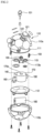
- FIG. 1 is a view illustrating a gas detection device according to an embodiment of the present invention
- FIG. 2 is an exploded view illustrating the gas detection device of FIG. 1 .
- a gas detection device 100 includes a case 110 in which a plurality of grooves H are formed in a circumferential surface of the case 110, an inlet 120 which is coupled to a first groove H1 among the grooves H and through which air is introduced into the case 110, a power button 130 which is coupled to a second groove H2 among the grooves H and turns a power source on or off, a gas detector 140 which is provided in the case 110 and detects a gas contained in the air introduced through the inlet 120, and a light unit 150 which is coupled to a third groove H3 among the grooves H and informs an on or off state of the power source and whether a gas is detected.
- the gas detection device 100 may include a battery 160 which supplies power, a beep generator 170 which generates a beep when a gas is detected, and a power switch 180 which is turned on or off by the power button 130.
- one or more of the inlet 120, the power button 130, and the light unit 150 are coupled to the grooves H in a recessed form.
- the case 110 may be formed in a portable spherical shape, and an outer cover of the case 110 may be formed of an elastic material.
- the case 110 may be provided in the spherical shape in which convex hexagonal covers are connected. Accordingly, the gas detection device 100 can be easily carried and thrown into a desired space.
- the gas detection device 100 may be manufactured in the small spherical shape which may be easily carried in a palm of an operator and moved by the operator, and a ring 101 may be provided at an upper end of the gas detection device 100 to be bound to an operator's clothes so that convenience of portability and movement can be improved.
- a strap (not shown) may be connected to the ring 101, the gas detection device 100 may be thrown into a place in which gas detection is required while the operator is holding the strap, and the gas detection device 100 may be easily collected by pulling the strap.
- a fishing line connected to a fishing rod may be connected to the ring 101, the gas detection device 100 may be thrown into a place in which gas detection is required, and then the gas detection device 100 may be collected by winding the fishing line.
- the gas detection device 100 may be thrown into a closed space or the like and detect gas or analyze gas components, and provide information to one or more external devices through data communication.
- the plurality of grooves H are formed, and one or more of the inlet 120, power button 130, and the light unit 150 may be coupled to the grooves H in a recessed form. Accordingly, when the gas detection device 100 is thrown, the inlet 120, the power button 130, and the light unit 150 can be prevented from being damaged by impact.
- the inlet 120, the power button 130, and the light unit 150 may be coupled to the first groove H1, the second groove H2, and the third groove H3, respectively, and each of the grooves H1 to H3 may be formed in a hexagonal shape.
- the first groove H1 in which the inlet 120 is provided may be provided as two or more first grooves H1 at set positions, and one second groove H2 in which the power button 130 is provided may be formed.
- the third groove H3, in which the light unit 150 is provided may be provided as two or more third grooves H3 at set positions.
- the case 110 may have a shape in which an upper case 110a having a hemispherical shape is coupled to a lower case 110b having a hemispherical shape.
- an O-ring 111 for sealing may be used therebetween.
- the case 110 may have the spherical shape formed by the upper case 110a and the lower case 110b that are coupled, and the outer cover of the case 110 may be formed of the elastic material including rubber. Accordingly, an impact, when the gas detection device 100 is thrown, can be reduced, and an operation of the gas detection device 100 can be performed normally.
- the outer cover of the case 110 may have a shape in which hexagonal shapes are consecutively arranged, and in another example, may be formed in a shape in which hexagonal shapes and pentagonal shapes are mixed. Accordingly, the gas detection device 100 can provide familiarity to the operator and reduce slippage, and thus the operator can easily grip the gas detection device 100 with a hand of the operator.
- the inlet 120 may be provided in each of two or more first grooves H1.
- the inlet 120 may include a filter 121 exposed to the outside and a guide member 122 having a hole through which air passing through the filter 121 flows to the gas detector 140.
- the filter 121 may filter impurities such as dust, and a plurality of holes may be formed in the filter 121 so that only particles having a predetermined size pass through the filter 121.
- the guide member 122 is disposed to support a lower portion of the filter 121 so that a fluid smoothly flows to the gas detector 140 inside the case 110.
- the power button 130 may press the power switch 180 inside the case 110 to turn the power source on, and when the power button 130 is pressed again, the power switch 180 may return to its original state so that the power source is turned off.
- the gas detector 140 detects gases contained in air introduced through the inlet 120.
- the gas detector 140 may include sensors and means for analyzing types, concentrations, and components of gases, and thus harmful gases can be detected.
- the gas detector 140 may transmit a gas detection signal to the light unit 150, the beep generator 170, and the like only when detecting the harmful gases.
- the light unit 150 may be provided in each of two or more of the third grooves H3 and may inform the outside of one or more states in which the power source is turned on or off and whether a gas is detected. For example, in the state in which the power source is turned on, the light unit 150 may inform the state by emitting light emitting diode (LED) light. In addition, when a gas detection signal is received from the gas detector 140, the light unit 150 can visually inform the outside of light repeatedly blinking at regular time intervals.
- the inlet 120, the power button 130, and the light unit 150 may be provided in circular shapes and coupled to the first groove H1, the second groove H2, and the third groove H3 in a recessed form.
- the battery 160 supplies electricity when the power button 130 is pressed.
- the battery 160 may supply electricity to one or more of the gas detector140, the light unit 150, and the beep generator170.
- the beep generator170 may generate a beep to audibly inform the outside of the beep.
- a surface of the case 110, on which the inlet 120 is installed face upward.
- the battery 160 which is relatively heavy compared to other means, may be disposed at a lower side in an inner portion of the case 110, a support frame 112 may be provided on the battery 160, and the gas detector 140, the beep generator 170, and the power switch 180 may be coupled to an upper portion of the support frame 112 so that a center of gravity is present at a lower portion of the case 110.
- the cylindrical battery 160 may be disposed horizontally under the support frame 112, and a seating groove or protrusion (not shown) may be provided in the lower case 110b so that the battery 160 is stably disposed.
- the support frame 112 may be formed as a circular flat plate matching an inner diameter of the spherical case 110 and disposed on the battery 15, and protrusions may be provided at two sides so that two ends of the battery 15 are hooked on a lower surface.
- installation lines may be drawn on an upper end of the support frame 112 to correspond to sizes and shapes of the cylindrical gas detector 140, the beep generator 170, and the power switch 180 so that the cylindrical gas detector 140, the beep generator 170, and the power switch 180 are disposed at designated positions.
- a coupling frame 113 and other auxiliary means which are relatively light may be provided above the gas detector 140, the beep generator 170, and the power switch 180.
- a coupling protrusion 113a may be formed at a lower center of the coupling frame 113, and the coupling frame 113 may be coupled to a coupling groove 170a formed in an upper portion of the beep generator 170.
- the gas detection device 100 of the present invention may include a transmitter 190 through which information on a harmful gas detected by the gas detector 140 is transmitted to a smartphone 200.
- An installation position of the transmitter 190 may be variously changed.
- the operator may install an application, which may perform data transmission and reception between the gas detection device 100 and the smartphone 200, in the smartphone 200, pairing is performed between the smartphone 200 and the gas detection device 100, and then the gas detection device 100 may be thrown into a place in which gas detection is required.
- an application which may perform data transmission and reception between the gas detection device 100 and the smartphone 200, in the smartphone 200, pairing is performed between the smartphone 200 and the gas detection device 100, and then the gas detection device 100 may be thrown into a place in which gas detection is required.
- the gas detection device 100 may transmit information on gas components, types, concentrations, and the like contained in air to the smartphone 200 in real time, and the operator may check the information through a screen of the smartphone 200.
- powering on or off of the gas detection device 100, the light unit 150, the beep generator 170, and the like may be controlled through the smartphone 200.
- the gas detection device 100 may operate in a 1:N manner with two or more smartphones 200.
- the gas detection devices 100 may also transmit detected information to the smartphone 200 through a well-known relay communication method or mesh communication method.
- One or more of the gas detection devices 100 can be conveniently carried, can be easily thrown into a place in which gas detection is required, can detect a gas in real time, and transmit information to an external device when the power source is simply turned on, and thus the gas detection device 100 is highly cost effective.
- the gas detection device 100 can prevent mortality accidents by generating LED light and a beep to call attention.
Landscapes
- Health & Medical Sciences (AREA)
- Physics & Mathematics (AREA)
- General Physics & Mathematics (AREA)
- General Health & Medical Sciences (AREA)
- Life Sciences & Earth Sciences (AREA)
- Engineering & Computer Science (AREA)
- Chemical & Material Sciences (AREA)
- Toxicology (AREA)
- Analytical Chemistry (AREA)
- Pathology (AREA)
- Biochemistry (AREA)
- Immunology (AREA)
- Molecular Biology (AREA)
- Business, Economics & Management (AREA)
- Emergency Management (AREA)
- Environmental & Geological Engineering (AREA)
- Biomedical Technology (AREA)
- Electrochemistry (AREA)
- Computer Networks & Wireless Communication (AREA)
- Electromagnetism (AREA)
- Chemical Kinetics & Catalysis (AREA)
- Combustion & Propulsion (AREA)
- Food Science & Technology (AREA)
- Medicinal Chemistry (AREA)
- Investigating Or Analyzing Materials By The Use Of Electric Means (AREA)
- Emergency Alarm Devices (AREA)
- Investigating Or Analyzing Materials By The Use Of Fluid Adsorption Or Reactions (AREA)
- Alarm Systems (AREA)
Abstract
Description
- The present invention relates to a gas detection device.
- When harmful gases exist in closed spaces, mortality accidents may occur. To prevent this, various gas detection devices have been conventionally used.
- However, since an operator has to carry a gas detection device and measure harmful gases, an accident risk still exists, and it is inconvenient to carry the gas detection device due to the weight of the gas detection device.
- In addition, since it is difficult to detect harmful gases in a deep and cramped place which is difficult for the operator to approach and additional means are required, installation and operation costs can be increased.
- An embodiment of the present invention is directed to providing a gas detection device which is easy to carry and capable of quickly detecting gases existing in any place by only throwing the gas detection device.
- One aspect of the present invention provides a gas detection device including a case in which a plurality of grooves are formed in a circumferential surface, an inlet which is coupled to a first groove among the grooves and through which air is introduced into the case, a power button which is coupled to a second groove among the grooves and turns a power source on or off, a gas detector which is provided in the case and detects a gas contained in the introduced air, a light unit which is coupled to a third groove among the grooves and informs a state in which the power source is turned on or off and whether the gas is detected, a battery which supplies power, a beep generator which generates a beep when a gas detection signal is received from the gas detector, and a power switch operated by the power button to turn on or off so as to supply the power from the battery, wherein one or more of the inlet, the power button, and the light unit are coupled to the grooves in a recessed form, the battery, the beep generator, and the power switch are provided inside the case, and the case is formed in a small spherical shape which is carried in a palm of an operator and moved by the operator.
- The case may have a shape in which an upper case having a hemispherical shape and a lower case having a hemispherical shape are coupled, and an outer cover of the case may be formed of an elastic material and formed in a shape in which hexagonal shapes are consecutively arranged.
- The inlet may include a filter exposed to the outside and a guide member in which a hole is formed so that air passing through the filter flows to the gas detector.
- The gas detection device may further include a support frame provided above the battery, wherein the battery, the support frame, and the gas detector coupled to an upper portion of the support frame, the beep generator, and the power switch may be sequentially disposed in the case from a lower side so that a center of gravity is present at a lower portion.
- The gas detection device may further include a transmitter through which information on the detected gas is transmitted to a smartphone.
- A gas detection device according to embodiments of the present invention is easy to carry and can quickly detect a gas existing in any place by only throwing the gas detection device.
- In addition, the presence of a gas can be immediately informed visually and audibly.
-
-
FIG. 1 is a view illustrating a gas detection device according to an embodiment of the present invention. -
FIG. 2 is an exploded view illustrating the gas detection device ofFIG. 1 . - Hereinafter, embodiments of the present disclosure will be described in detail with reference to the accompanying drawings. The embodiments, which will be described below, are examples which provide the concept of the present disclosure to those skilled in the art. The present disclosure is not limited to the embodiments, and may be implemented in different forms. Parts irrelevant to description are omitted in the drawings in order to clearly describe the present disclosure, and widths, lengths, and thicknesses of components in the drawings may be exaggerated for convenience of description. In this specification, like reference characters denote like components.
-
FIG. 1 is a view illustrating a gas detection device according to an embodiment of the present invention, andFIG. 2 is an exploded view illustrating the gas detection device ofFIG. 1 . - Referring to
FIGS. 1 and2 , agas detection device 100 includes acase 110 in which a plurality of grooves H are formed in a circumferential surface of thecase 110, aninlet 120 which is coupled to a first groove H1 among the grooves H and through which air is introduced into thecase 110, apower button 130 which is coupled to a second groove H2 among the grooves H and turns a power source on or off, agas detector 140 which is provided in thecase 110 and detects a gas contained in the air introduced through theinlet 120, and alight unit 150 which is coupled to a third groove H3 among the grooves H and informs an on or off state of the power source and whether a gas is detected. - In addition, the
gas detection device 100 may include abattery 160 which supplies power, abeep generator 170 which generates a beep when a gas is detected, and apower switch 180 which is turned on or off by thepower button 130. - In this case, one or more of the
inlet 120, thepower button 130, and thelight unit 150 are coupled to the grooves H in a recessed form. - In addition, the
case 110 may be formed in a portable spherical shape, and an outer cover of thecase 110 may be formed of an elastic material. Thecase 110 may be provided in the spherical shape in which convex hexagonal covers are connected. Accordingly, thegas detection device 100 can be easily carried and thrown into a desired space. - The
gas detection device 100 may be manufactured in the small spherical shape which may be easily carried in a palm of an operator and moved by the operator, and aring 101 may be provided at an upper end of thegas detection device 100 to be bound to an operator's clothes so that convenience of portability and movement can be improved. - In addition, a strap (not shown) may be connected to the
ring 101, thegas detection device 100 may be thrown into a place in which gas detection is required while the operator is holding the strap, and thegas detection device 100 may be easily collected by pulling the strap. For example, a fishing line connected to a fishing rod may be connected to thering 101, thegas detection device 100 may be thrown into a place in which gas detection is required, and then thegas detection device 100 may be collected by winding the fishing line. - The
gas detection device 100 may be thrown into a closed space or the like and detect gas or analyze gas components, and provide information to one or more external devices through data communication. - Hereinafter, each component of the
gas detection device 100 will be described in detail. - In the circumferential surface of the
case 110, the plurality of grooves H are formed, and one or more of theinlet 120,power button 130, and thelight unit 150 may be coupled to the grooves H in a recessed form. Accordingly, when thegas detection device 100 is thrown, theinlet 120, thepower button 130, and thelight unit 150 can be prevented from being damaged by impact. Theinlet 120, thepower button 130, and thelight unit 150 may be coupled to the first groove H1, the second groove H2, and the third groove H3, respectively, and each of the grooves H1 to H3 may be formed in a hexagonal shape. The first groove H1 in which theinlet 120 is provided may be provided as two or more first grooves H1 at set positions, and one second groove H2 in which thepower button 130 is provided may be formed. In addition, the third groove H3, in which thelight unit 150 is provided, may be provided as two or more third grooves H3 at set positions. - The
case 110 may have a shape in which anupper case 110a having a hemispherical shape is coupled to alower case 110b having a hemispherical shape. When theupper case 110a and thelower case 110b are coupled, an O-ring 111 for sealing may be used therebetween. - The
case 110 may have the spherical shape formed by theupper case 110a and thelower case 110b that are coupled, and the outer cover of thecase 110 may be formed of the elastic material including rubber. Accordingly, an impact, when thegas detection device 100 is thrown, can be reduced, and an operation of thegas detection device 100 can be performed normally. - In addition, the outer cover of the
case 110 may have a shape in which hexagonal shapes are consecutively arranged, and in another example, may be formed in a shape in which hexagonal shapes and pentagonal shapes are mixed. Accordingly, thegas detection device 100 can provide familiarity to the operator and reduce slippage, and thus the operator can easily grip thegas detection device 100 with a hand of the operator. - The
inlet 120 may be provided in each of two or more first grooves H1. Theinlet 120 may include afilter 121 exposed to the outside and aguide member 122 having a hole through which air passing through thefilter 121 flows to thegas detector 140. - The
filter 121 may filter impurities such as dust, and a plurality of holes may be formed in thefilter 121 so that only particles having a predetermined size pass through thefilter 121. Theguide member 122 is disposed to support a lower portion of thefilter 121 so that a fluid smoothly flows to thegas detector 140 inside thecase 110. - The
power button 130 may press thepower switch 180 inside thecase 110 to turn the power source on, and when thepower button 130 is pressed again, thepower switch 180 may return to its original state so that the power source is turned off. - The
gas detector 140 detects gases contained in air introduced through theinlet 120. Thegas detector 140 may include sensors and means for analyzing types, concentrations, and components of gases, and thus harmful gases can be detected. Thegas detector 140 may transmit a gas detection signal to thelight unit 150, thebeep generator 170, and the like only when detecting the harmful gases. - The
light unit 150 may be provided in each of two or more of the third grooves H3 and may inform the outside of one or more states in which the power source is turned on or off and whether a gas is detected. For example, in the state in which the power source is turned on, thelight unit 150 may inform the state by emitting light emitting diode (LED) light. In addition, when a gas detection signal is received from thegas detector 140, thelight unit 150 can visually inform the outside of light repeatedly blinking at regular time intervals. Theinlet 120, thepower button 130, and thelight unit 150 may be provided in circular shapes and coupled to the first groove H1, the second groove H2, and the third groove H3 in a recessed form. - The
battery 160 supplies electricity when thepower button 130 is pressed. For example, thebattery 160 may supply electricity to one or more of the gas detector140, thelight unit 150, and the beep generator170. - When receiving a gas detection signal from the gas detector140, the beep generator170 may generate a beep to audibly inform the outside of the beep.
- Meanwhile, when the
gas detection device 100 is thrown into a closed space, it is preferable that a surface of thecase 110, on which theinlet 120 is installed, face upward. - To this end, the
battery 160, which is relatively heavy compared to other means, may be disposed at a lower side in an inner portion of thecase 110, asupport frame 112 may be provided on thebattery 160, and thegas detector 140, thebeep generator 170, and thepower switch 180 may be coupled to an upper portion of thesupport frame 112 so that a center of gravity is present at a lower portion of thecase 110. - Specifically, the
cylindrical battery 160 may be disposed horizontally under thesupport frame 112, and a seating groove or protrusion (not shown) may be provided in thelower case 110b so that thebattery 160 is stably disposed. - The
support frame 112 may be formed as a circular flat plate matching an inner diameter of thespherical case 110 and disposed on the battery 15, and protrusions may be provided at two sides so that two ends of the battery 15 are hooked on a lower surface. In addition, installation lines may be drawn on an upper end of thesupport frame 112 to correspond to sizes and shapes of thecylindrical gas detector 140, thebeep generator 170, and thepower switch 180 so that thecylindrical gas detector 140, thebeep generator 170, and thepower switch 180 are disposed at designated positions. - In addition, a
coupling frame 113 and other auxiliary means which are relatively light may be provided above thegas detector 140, thebeep generator 170, and thepower switch 180. - A
coupling protrusion 113a may be formed at a lower center of thecoupling frame 113, and thecoupling frame 113 may be coupled to acoupling groove 170a formed in an upper portion of thebeep generator 170. - The
gas detection device 100 of the present invention may include atransmitter 190 through which information on a harmful gas detected by thegas detector 140 is transmitted to asmartphone 200. An installation position of thetransmitter 190 may be variously changed. - The operator may install an application, which may perform data transmission and reception between the
gas detection device 100 and thesmartphone 200, in thesmartphone 200, pairing is performed between thesmartphone 200 and thegas detection device 100, and then thegas detection device 100 may be thrown into a place in which gas detection is required. - The
gas detection device 100 may transmit information on gas components, types, concentrations, and the like contained in air to thesmartphone 200 in real time, and the operator may check the information through a screen of thesmartphone 200. - In addition, in another example, powering on or off of the
gas detection device 100, thelight unit 150, thebeep generator 170, and the like may be controlled through thesmartphone 200. - The
gas detection device 100 may operate in a 1:N manner with two ormore smartphones 200. - In addition, when two or more
gas detection devices 100 are thrown, thegas detection devices 100 may also transmit detected information to thesmartphone 200 through a well-known relay communication method or mesh communication method. - One or more of the
gas detection devices 100 can be conveniently carried, can be easily thrown into a place in which gas detection is required, can detect a gas in real time, and transmit information to an external device when the power source is simply turned on, and thus thegas detection device 100 is highly cost effective. - In addition, the
gas detection device 100 can prevent mortality accidents by generating LED light and a beep to call attention. - The specific embodiments have been illustrated and described above. However, the present disclosure is not limited in the above-described embodiments and may be variously changed without limitation by those skilled in the art without departing from the gist of the technical sprit described in the appended claims.
Claims (5)
- A gas detection device comprising:a case in which a plurality of grooves are formed in a circumferential surface;an inlet which is coupled to a first groove among the grooves and through which air is introduced into the case;a power button which is coupled to a second groove among the grooves and turns a power source on or off;a gas detector which is provided in the case and detects a gas contained in the introduced air;a light unit which is coupled to a third groove among the grooves and emits light to inform an outside of one or more states in which the power source is turned on or off and whether the gas is detected;a battery which supplies power;a beep generator which generates a beep when a gas detection signal is received from the gas detector; anda power switch operated by the power button to turn on or off so as to supply the power from the battery,wherein one or more of the inlet, the power button, and the light unit are coupled to the grooves in a recessed form,the battery, the beep generator, and the power switch are provided inside the case, andthe case is formed in a small spherical shape which is carried in a palm of an operator and moved by the operator.
- The gas detection device of claim 1, wherein:the case has a shape in which an upper case having a hemispherical shape and a lower case having a hemispherical shape are coupled; andan outer cover of the case is formed of an elastic material and formed in a shape in which hexagonal shapes are consecutively arranged.
- The gas detection device of claim 1, wherein the inlet includes:a filter exposed to the outside; anda guide member in which a hole is formed so that air passing through the filter flows to the gas detector.
- The gas detection device of claim 1, further comprising a support frame provided above the battery,
wherein the battery, the support frame, and the gas detector coupled to an upper portion of the support frame, the beep generator, and the power switch are sequentially disposed in the case from a lower side so that a center of gravity is present at a lower portion. - The gas detection device of claim 1, further comprising a transmitter through which information on the detected gas is transmitted to a smartphone.
Applications Claiming Priority (2)
| Application Number | Priority Date | Filing Date | Title |
|---|---|---|---|
| KR1020200178275A KR102570088B1 (en) | 2020-12-18 | 2020-12-18 | Apparatus for detecting gas |
| PCT/KR2021/011770 WO2022131484A1 (en) | 2020-12-18 | 2021-09-01 | Gas detection device |
Publications (2)
| Publication Number | Publication Date |
|---|---|
| EP4266035A1 true EP4266035A1 (en) | 2023-10-25 |
| EP4266035A4 EP4266035A4 (en) | 2024-12-11 |
Family
ID=82057858
Family Applications (1)
| Application Number | Title | Priority Date | Filing Date |
|---|---|---|---|
| EP21906789.9A Pending EP4266035A4 (en) | 2020-12-18 | 2021-09-01 | GAS DETECTION DEVICE |
Country Status (6)
| Country | Link |
|---|---|
| US (1) | US12217594B2 (en) |
| EP (1) | EP4266035A4 (en) |
| JP (1) | JP7561998B2 (en) |
| KR (1) | KR102570088B1 (en) |
| CN (1) | CN116783635A (en) |
| WO (1) | WO2022131484A1 (en) |
Families Citing this family (1)
| Publication number | Priority date | Publication date | Assignee | Title |
|---|---|---|---|---|
| KR102768879B1 (en) * | 2023-12-26 | 2025-02-19 | 주식회사 케이알산업 | Communication manhole gas sensing device capable of remote and manual sensing |
Family Cites Families (16)
| Publication number | Priority date | Publication date | Assignee | Title |
|---|---|---|---|---|
| JP2620787B2 (en) * | 1987-07-31 | 1997-06-18 | 株式会社ジャルコ | Odor measuring instrument |
| JPH11160277A (en) * | 1997-11-28 | 1999-06-18 | Shimadzu Corp | Portable gas meter |
| KR100441678B1 (en) * | 2001-07-19 | 2004-07-27 | 주식회사 진산물산 | Device and method for preventing wear of gas sensors |
| WO2007120898A2 (en) | 2006-04-13 | 2007-10-25 | Quantum Group Inc. | Carbon monoxide (co) microsir sensor system |
| US8537020B2 (en) * | 2008-12-23 | 2013-09-17 | Honeywell International Inc. | Visual indicator of gas sensor impairment |
| KR20110038213A (en) * | 2009-10-08 | 2011-04-14 | 주식회사코어벨 | Environmental information measuring ball |
| KR200477918Y1 (en) | 2014-04-15 | 2015-08-05 | 주식회사 이제갬 | Air measuring apparatus |
| KR101588415B1 (en) * | 2015-03-30 | 2016-01-25 | 송창영 | Search device for human body harmful field |
| KR101947598B1 (en) * | 2015-09-02 | 2019-04-22 | 정주환 | Portable gas detecting apparatus and gas detecting system therewith |
| US10041918B2 (en) * | 2015-11-10 | 2018-08-07 | Nuxtu S.A.S. | Electronic nose and tongue device for real-time monitoring and analysis of liquid and gaseous substances |
| US20180321209A1 (en) | 2015-11-10 | 2018-11-08 | Nuxtu S.A.S | Methods and processes for detection of a substance using an electronic nose and tongue device |
| CN106052736B (en) * | 2016-07-18 | 2018-06-26 | 西安电子科技大学 | The node protective cover of ZigBee technology environmental monitoring system |
| KR20180079788A (en) * | 2017-01-02 | 2018-07-11 | (주)공존연구소 | Smart phone combined industrial wearable device equipped with sensor and communication module |
| AU2019229185A1 (en) * | 2018-02-27 | 2020-07-23 | TeleSense, Inc. | Method and apparatus for remote monitoring and management of storage using machine learning and data analytics |
| KR101972057B1 (en) * | 2018-12-13 | 2019-04-24 | 한국가스안전공사 | Intelligent Gas Density and Water Level Measuring System based on IoT |
| KR102045277B1 (en) * | 2019-05-27 | 2019-11-15 | 주식회사 오투 | Detachable oxygen concentration and hazardous gas alarm using band |
-
2020
- 2020-12-18 KR KR1020200178275A patent/KR102570088B1/en active Active
-
2021
- 2021-09-01 EP EP21906789.9A patent/EP4266035A4/en active Pending
- 2021-09-01 JP JP2023537420A patent/JP7561998B2/en active Active
- 2021-09-01 WO PCT/KR2021/011770 patent/WO2022131484A1/en not_active Ceased
- 2021-09-01 US US18/268,171 patent/US12217594B2/en active Active
- 2021-09-01 CN CN202180090358.6A patent/CN116783635A/en active Pending
Also Published As
| Publication number | Publication date |
|---|---|
| WO2022131484A1 (en) | 2022-06-23 |
| US20240296731A1 (en) | 2024-09-05 |
| KR102570088B1 (en) | 2023-08-23 |
| JP2024500149A (en) | 2024-01-04 |
| KR20220087848A (en) | 2022-06-27 |
| EP4266035A4 (en) | 2024-12-11 |
| CN116783635A (en) | 2023-09-19 |
| US12217594B2 (en) | 2025-02-04 |
| JP7561998B2 (en) | 2024-10-04 |
Similar Documents
| Publication | Publication Date | Title |
|---|---|---|
| KR101526950B1 (en) | Safety belt and system for checking a usage status of the safety belt | |
| US12217594B2 (en) | Gas detection device | |
| US8103459B2 (en) | Safety clothing | |
| KR101800971B1 (en) | Multi camping lantern | |
| KR200454894Y1 (en) | Multifunctional Smoke Lantern | |
| KR102217765B1 (en) | Safety device for the prevention of falling of the high place worker and safety system using the same | |
| CN110429502B (en) | Waist-mounted power distribution network inspection system | |
| KR20130120279A (en) | System for measuring radioactive rays and radioactivity | |
| US20110304480A1 (en) | Apparatus for locating one mooring in a field of moorings | |
| US10669117B2 (en) | Portable rope guiding apparatus | |
| JP4695502B2 (en) | Helmet with gas detector and gas detector for helmet mounting | |
| KR102317800B1 (en) | A Locking Type of an Indicating Apparatus for a Safety Cap and the Safety Cap with the Same | |
| KR102540115B1 (en) | Safety vest for checking facility safety | |
| US20180350206A1 (en) | System and method for providing portable light | |
| CN111210608A (en) | Remote control device and remote control method thereof | |
| KR20230086298A (en) | Safety hook fastening detection device | |
| KR101843880B1 (en) | Safety equipment of locking sensor | |
| KR101588415B1 (en) | Search device for human body harmful field | |
| CN210539580U (en) | Children prevent losing knapsack | |
| JP6644840B2 (en) | Fall detection device and monitoring system equipped with the fall detection device | |
| KR20220021557A (en) | Double beacon system for checking out safety apparatus state of worker in construction filed | |
| CN106457004A (en) | brake device and monitoring system thereof | |
| EP3498093A1 (en) | A fishing appliance and a fishing accessory | |
| KR102169217B1 (en) | Portable GPS Device Active Type | |
| JP2006306526A (en) | Crane alarm device |
Legal Events
| Date | Code | Title | Description |
|---|---|---|---|
| STAA | Information on the status of an ep patent application or granted ep patent |
Free format text: STATUS: THE INTERNATIONAL PUBLICATION HAS BEEN MADE |
|
| PUAI | Public reference made under article 153(3) epc to a published international application that has entered the european phase |
Free format text: ORIGINAL CODE: 0009012 |
|
| STAA | Information on the status of an ep patent application or granted ep patent |
Free format text: STATUS: REQUEST FOR EXAMINATION WAS MADE |
|
| 17P | Request for examination filed |
Effective date: 20230616 |
|
| AK | Designated contracting states |
Kind code of ref document: A1 Designated state(s): AL AT BE BG CH CY CZ DE DK EE ES FI FR GB GR HR HU IE IS IT LI LT LU LV MC MK MT NL NO PL PT RO RS SE SI SK SM TR |
|
| DAV | Request for validation of the european patent (deleted) | ||
| DAX | Request for extension of the european patent (deleted) | ||
| A4 | Supplementary search report drawn up and despatched |
Effective date: 20241111 |
|
| RIC1 | Information provided on ipc code assigned before grant |
Ipc: G01D 11/24 20060101ALI20241105BHEP Ipc: G01N 27/22 20060101ALI20241105BHEP Ipc: G01N 15/00 20060101ALI20241105BHEP Ipc: G08B 7/06 20060101ALI20241105BHEP Ipc: G08B 21/14 20060101ALI20241105BHEP Ipc: G01N 27/26 20060101AFI20241105BHEP |