EP4266015A1 - System for monitoring a switchgear - Google Patents
System for monitoring a switchgear Download PDFInfo
- Publication number
- EP4266015A1 EP4266015A1 EP22169229.6A EP22169229A EP4266015A1 EP 4266015 A1 EP4266015 A1 EP 4266015A1 EP 22169229 A EP22169229 A EP 22169229A EP 4266015 A1 EP4266015 A1 EP 4266015A1
- Authority
- EP
- European Patent Office
- Prior art keywords
- temperature
- infrared image
- pixels
- switchgear
- infrared
- Prior art date
- Legal status (The legal status is an assumption and is not a legal conclusion. Google has not performed a legal analysis and makes no representation as to the accuracy of the status listed.)
- Granted
Links
Images


Classifications
-
- G—PHYSICS
- G06—COMPUTING OR CALCULATING; COUNTING
- G06T—IMAGE DATA PROCESSING OR GENERATION, IN GENERAL
- G06T7/00—Image analysis
- G06T7/0002—Inspection of images, e.g. flaw detection
- G06T7/0004—Industrial image inspection
-
- G—PHYSICS
- G01—MEASURING; TESTING
- G01J—MEASUREMENT OF INTENSITY, VELOCITY, SPECTRAL CONTENT, POLARISATION, PHASE OR PULSE CHARACTERISTICS OF INFRARED, VISIBLE OR ULTRAVIOLET LIGHT; COLORIMETRY; RADIATION PYROMETRY
- G01J5/00—Radiation pyrometry, e.g. infrared or optical thermometry
- G01J5/0066—Radiation pyrometry, e.g. infrared or optical thermometry for hot spots detection
-
- G—PHYSICS
- G01—MEASURING; TESTING
- G01R—MEASURING ELECTRIC VARIABLES; MEASURING MAGNETIC VARIABLES
- G01R31/00—Arrangements for testing electric properties; Arrangements for locating electric faults; Arrangements for electrical testing characterised by what is being tested not provided for elsewhere
- G01R31/327—Testing of circuit interrupters, switches or circuit-breakers
-
- G—PHYSICS
- G01—MEASURING; TESTING
- G01J—MEASUREMENT OF INTENSITY, VELOCITY, SPECTRAL CONTENT, POLARISATION, PHASE OR PULSE CHARACTERISTICS OF INFRARED, VISIBLE OR ULTRAVIOLET LIGHT; COLORIMETRY; RADIATION PYROMETRY
- G01J5/00—Radiation pyrometry, e.g. infrared or optical thermometry
- G01J5/0096—Radiation pyrometry, e.g. infrared or optical thermometry for measuring wires, electrical contacts or electronic systems
-
- G—PHYSICS
- G01—MEASURING; TESTING
- G01J—MEASUREMENT OF INTENSITY, VELOCITY, SPECTRAL CONTENT, POLARISATION, PHASE OR PULSE CHARACTERISTICS OF INFRARED, VISIBLE OR ULTRAVIOLET LIGHT; COLORIMETRY; RADIATION PYROMETRY
- G01J5/00—Radiation pyrometry, e.g. infrared or optical thermometry
- G01J5/48—Thermography; Techniques using wholly visual means
-
- G—PHYSICS
- G01—MEASURING; TESTING
- G01J—MEASUREMENT OF INTENSITY, VELOCITY, SPECTRAL CONTENT, POLARISATION, PHASE OR PULSE CHARACTERISTICS OF INFRARED, VISIBLE OR ULTRAVIOLET LIGHT; COLORIMETRY; RADIATION PYROMETRY
- G01J5/00—Radiation pyrometry, e.g. infrared or optical thermometry
- G01J5/48—Thermography; Techniques using wholly visual means
- G01J5/485—Temperature profile
-
- G—PHYSICS
- G06—COMPUTING OR CALCULATING; COUNTING
- G06T—IMAGE DATA PROCESSING OR GENERATION, IN GENERAL
- G06T5/00—Image enhancement or restoration
- G06T5/50—Image enhancement or restoration using two or more images, e.g. averaging or subtraction
-
- G—PHYSICS
- G06—COMPUTING OR CALCULATING; COUNTING
- G06T—IMAGE DATA PROCESSING OR GENERATION, IN GENERAL
- G06T7/00—Image analysis
- G06T7/10—Segmentation; Edge detection
- G06T7/11—Region-based segmentation
-
- G—PHYSICS
- G06—COMPUTING OR CALCULATING; COUNTING
- G06T—IMAGE DATA PROCESSING OR GENERATION, IN GENERAL
- G06T7/00—Image analysis
- G06T7/10—Segmentation; Edge detection
- G06T7/136—Segmentation; Edge detection involving thresholding
-
- G—PHYSICS
- G06—COMPUTING OR CALCULATING; COUNTING
- G06V—IMAGE OR VIDEO RECOGNITION OR UNDERSTANDING
- G06V10/00—Arrangements for image or video recognition or understanding
- G06V10/40—Extraction of image or video features
- G06V10/56—Extraction of image or video features relating to colour
-
- G—PHYSICS
- G06—COMPUTING OR CALCULATING; COUNTING
- G06V—IMAGE OR VIDEO RECOGNITION OR UNDERSTANDING
- G06V20/00—Scenes; Scene-specific elements
- G06V20/50—Context or environment of the image
- G06V20/52—Surveillance or monitoring of activities, e.g. for recognising suspicious objects
-
- G—PHYSICS
- G01—MEASURING; TESTING
- G01J—MEASUREMENT OF INTENSITY, VELOCITY, SPECTRAL CONTENT, POLARISATION, PHASE OR PULSE CHARACTERISTICS OF INFRARED, VISIBLE OR ULTRAVIOLET LIGHT; COLORIMETRY; RADIATION PYROMETRY
- G01J5/00—Radiation pyrometry, e.g. infrared or optical thermometry
- G01J2005/0077—Imaging
-
- G—PHYSICS
- G06—COMPUTING OR CALCULATING; COUNTING
- G06T—IMAGE DATA PROCESSING OR GENERATION, IN GENERAL
- G06T2207/00—Indexing scheme for image analysis or image enhancement
- G06T2207/10—Image acquisition modality
- G06T2207/10048—Infrared image
Definitions
- the present invention relates to a system for monitoring a switchgear, a method for monitoring a switchgear, to a switchgear having such a system, and a computer program element.
- switchgear can suffer from small faults that change the electrical resistance of the system. These faults manifest as hot spots and can ultimately lead to catastrophic failures.
- a switchgear can be a high voltage, medium voltage, or low voltage switchgear.
- thermographic camera monitor parts of the switchgear, such as the phases, with an infrared thermographic camera to detect the hot spots.
- IR infrared
- a system for monitoring a switchgear comprising:
- the infrared camera is configured to acquire a first infrared image of the switchgear, and a total number of pixels in the first infrared image is equal to a first number.
- the processing unit is configured to determine a pixel in the first infrared image with a maximum temperature in the first infrared image.
- the processing unit is configured to utilize a second number of pixels less than the first number of pixels to determine a temperature interval for the first infrared image equal to a difference between the maximum temperature in the first infrared image and a threshold temperature in the first infrared image.
- the processing unit is configured to sort the pixels in the infrared image in descending order of temperature from the maximum temperature and determine the threshold temperature in the first infrared image as a temperature of a pixel in the first infrared image that is the pixel placed a set number in the sorted order of pixels in the descending order of temperature from the maximum temperature, and the set number is equal to the second number of pixels.
- the processing unit is configured to determine that a hot spot exists in the switchgear. The determination that the hot spot exists comprises utilization of the temperature interval for the first infrared image.
- the output unit is configured to output an indication of a fault in the switchgear when the determination has been made that a hot spot exists in the switchgear.
- infrared imagery of a switchgear is acquired, for example of the three phases.
- Each image could have 1024 pixels.
- a number such as 300 is selected.
- an image is analysed to determine the maximum or hottest temperature in an image. For example this could be 60.5C.
- the pixels are sorted in decreasing order of temperature.
- the pixel 300 from the maximum temperature in the descending list of pixel temperatures is identified. This for example could have a temperature of 51.5C.
- the temperature interval is then 60.5C minus 51.5C equal to 9C. And this temperature interval can be used to determine if there is a hot spot in the image.
- a temperature span of for example current carrying phases of a switchgear can indicate is there is a hotspot without requiring a detailed understanding of the image structure.
- the new temperature monitoring system can be used to determine whether there are hot spots in the image that indicate faults in the switchgear system.
- the temperature interval of 9C can be associated with a correctly functioning switchgear with no hot spots.
- a hot spot develops the maximum temperature is again identified and the pixels are again sorted in descending order of temperature, and the pixel 300 from the top again identified and its temperature identified to determine a new temperature interval. If there is a hot spot, then the temperature interval will be greater than 9C and this can be used to determine that there is a hot spot.
- the second number is a predetermined number.
- the second number is determined from one or more calibration infrared images of the, or a similar, switchgear.
- the determination that the hot spot exists comprises utilization of the maximum temperature in the first infrared image.
- the determination that the hot spot exists comprises a determination that the temperature interval for the first infrared image is greater than a threshold temperature interval value.
- the threshold temperature interval value is determined as a function of the maximum temperature in the first infrared image.
- the infrared camera is configured to acquire a second infrared image of the switchgear after acquisition of the first infrared image of the switchgear, and a total number of pixels in the second infrared image is equal to the first number.
- the processing unit is configured to determine a pixel in the second infrared image with a maximum temperature in the second infrared image.
- the processing unit is configured to utilize the second number of pixels to determine a temperature interval for the second infrared image equal to a difference between the maximum temperature in the second infrared image and a threshold temperature in the second infrared image.
- the processing unit is configured to sort the pixels in the second infrared image in descending order of temperature from the maximum temperature in the second infrared image and determine the threshold temperature in the second infrared image as a temperature of a pixel in the second infrared image that is the pixel placed the set number in the sorted order of pixels in the descending order of temperature from the maximum temperature.
- the processing unit is configured to determine that the hot spot exists in the switchgear on the basis that the temperature interval for the second infrared image is greater than the temperature interval for the first infrared image.
- the processing unit is configured to determine that the hot spot exists in the switchgear on the basis that the temperature interval for the second infrared image is greater than the temperature interval for the first infrared image by a set amount.
- the set amount is 0,5C, 1C, 1.5C ... 3C.
- the set amount is determined as a function of the maximum temperature.
- the infrared camera is configured to acquire a plurality of infrared images of the switchgear after acquisition of the first infrared image of the switchgear, and a total number of pixels in each of the plurality of infrared images is equal to the first number.
- the processing unit is configured to determine a pixel in each of plurality of infrareds image with a maximum temperature in the each of the plurality of infrared images.
- the processing unit is configured to utilize the second number of pixels to determine a temperature interval for each of the plurality of infrared images equal to a difference between the maximum temperature in the each of the plurality of infrared images and a threshold temperature in each of the plurality of infrared images.
- the processing unit is configured to sort the pixels in each of the plurality of infrared images in descending order of temperature from the maximum temperature in each of the plurality of infrared images and determine the threshold temperature in each of the plurality of infrared images as a temperature of a pixel in each of the plurality of infrared images that is the pixel placed the set number in the sorted order of pixels in the descending order of temperature from the maximum temperature.
- the processing unit is configured to determine that the hot spot exists in the switchgear on the basis of a rate of change between adjacent temperature intervals of the temperature interval for the first infrared image and the temperature intervals for the plurality of infrared images.
- the determination that the hot spot exists comprises utilization of a machine learning algorithm
- the machine learning algorithm is a trained neural network.
- the system comprises a visible camera configured to acquire a visible image of the switchgear.
- the processing unit is configured to overlay a location of a maximum temperature in an infrared image onto a corresponding location in the visible image.
- the processing unit is configured to overlay locations of pixels having a temperature between a threshold temperature and the maximum temperature in an infrared image onto corresponding locations in the visible image.
- the location of hot pixels can be mapped to a visible image in order to allow a human to review the situation to determine if there is a fault.
- a switchgear comprising a system according to the first aspect.
- a method for monitoring a switchgear comprises:
- a computer program element controlling one or more of the systems as previously described which, if the computer program element is executed by a processor, is adapted to perform the methods as previously described.
- a computer readable medium having stored a computer element as previously described.
- the computer program element can for example be a software program but can also be a FPGA, a PLD or any other appropriate digital means.
- Figs. 1-7 provide details explaining a new system for monitoring a switchgear.
- the system comprises an infrared camera, a processing unit, and an output unit.
- the infrared camera is configured to acquire a first infrared image of the switchgear, and a total number of pixels in the first infrared image is equal to a first number.
- the processing unit is configured to determine a pixel in the first infrared image with a maximum temperature in the first infrared image.
- the processing unit is configured to utilize a second number of pixels less than the first number of pixels to determine a temperature interval for the first infrared image equal to a difference between the maximum temperature in the first infrared image and a threshold temperature in the first infrared image.
- the processing unit is configured to sort the pixels in the infrared image in descending order of temperature from the maximum temperature and determine the threshold temperature in the first infrared image as a temperature of a pixel in the first infrared image that is the pixel placed a set number in the sorted order of pixels in the descending order of temperature from the maximum temperature. The set number is equal to the second number of pixels.
- the processing unit is configured to determine that a hot spot exists in the switchgear. The determination that the hot spot exists comprises utilization of the temperature interval for the first infrared image.
- the output unit is configured to output an indication of a fault in the switchgear when the determination has been made that a hot spot exists in the switchgear.
- the second number is determined from an infrared image captured by the infrared camera, or an equivalent infrared camera, of the switchgear, or an equivalent switchgear, such that the second number is a number of pixels in the infrared image that have the highest temperature values and that cover the parts of the switchgear, such as the phases or parts of the phases, that are required to be monitored.
- a correctly functioning switchgear can be imaged and the number of the hottest pixels varied until the associated parts of the image cover the parts of the switchgear required to be monitored.
- This sets the second number (say X), and is then used to identify the hottest X pixels in subsequent images and the temperature threshold which along with the maximum temperature provides the associated temperature interval that is used to indicate if there is a hot spot or not.
- the second number is a predetermined number.
- the second number is determined from one or more calibration infrared images of the, or a similar, switchgear.
- the determination that the hot spot exists comprises utilization of the maximum temperature in the first infrared image.
- the determination that the hot spot exists comprises a determination that the temperature interval for the first infrared image is greater than a threshold temperature interval value.
- the threshold temperature interval value is determined as a function of the maximum temperature in the first infrared image.
- the infrared camera is configured to acquire a second infrared image of the switchgear after acquisition of the first infrared image of the switchgear, and a total number of pixels in the second infrared image is equal to the first number.
- the processing unit is configured to determine a pixel in the second infrared image with a maximum temperature in the second infrared image.
- the processing unit is configured to utilize the second number of pixels to determine a temperature interval for the second infrared image equal to a difference between the maximum temperature in the second infrared image and a threshold temperature in the second infrared image.
- the processing unit is configured to sort the pixels in the second infrared image in descending order of temperature from the maximum temperature in the second infrared image and determine the threshold temperature in the second infrared image as a temperature of a pixel in the second infrared image that is the pixel placed the set number in the sorted order of pixels in the descending order of temperature from the maximum temperature.
- the processing unit is configured to determine that the hot spot exists in the switchgear on the basis that the temperature interval for the second infrared image is greater than the temperature interval for the first infrared image.
- the processing unit is configured to determine that the hot spot exists in the switchgear on the basis that the temperature interval for the second infrared image is greater than the temperature interval for the first infrared image by a set amount.
- the set amount is 0,5C, 1C, 1.5C ... 3C.
- the set amount is determined as a function of the maximum temperature.
- the infrared camera is configured to acquire a plurality of infrared images of the switchgear after acquisition of the first infrared image of the switchgear, and a total number of pixels in each of the plurality of infrared images is equal to the first number.
- the processing unit is configured to determine a pixel in each of plurality of infrareds image with a maximum temperature in the each of the plurality of infrared images.
- the processing unit is configured to utilize the second number of pixels to determine a temperature interval for each of the plurality of infrared images equal to a difference between the maximum temperature in the each of the plurality of infrared images and a threshold temperature in each of the plurality of infrared images.
- the processing unit is configured to sort the pixels in each of the plurality of infrared images in descending order of temperature from the maximum temperature in each of the plurality of infrared images and determine the threshold temperature in each of the plurality of infrared images as a temperature of a pixel in each of the plurality of infrared images that is the pixel placed the set number in the sorted order of pixels in the descending order of temperature from the maximum temperature.
- the processing unit is configured to determine that the hot spot exists in the switchgear on the basis of a rate of change between adjacent temperature intervals of the temperature interval for the first infrared image and the temperature intervals for the plurality of infrared images.
- the determination that the hot spot exists comprises utilization of a machine learning algorithm
- the machine learning algorithm is a trained neural network.
- the system comprises a visible camera configured to acquire a visible image of the switchgear.
- the processing unit is configured to overlay a location of a maximum temperature in an infrared image onto a corresponding location in the visible image.
- the processing unit is configured to overlay locations of pixels having a temperature between a threshold temperature and the maximum temperature in an infrared image onto corresponding locations in the visible image.
- a switchgear can comprising such a system as described above, whether retrofitted to an existing switchgear, or provided with a switchgear as it is built.
- an associated method for monitoring a switchgear comprises:
- the second number is a predetermined number.
- the second number is determined from one or more calibration infrared images of the, or a similar, switchgear.
- the determining that the hot spot exists comprises utilizing the maximum temperature in the first infrared image.
- the determining that the hot spot exists comprises determining that the temperature interval for the first infrared image is greater than a threshold temperature interval value.
- the threshold temperature interval value is determined as a function of the maximum temperature in the first infrared image.
- the method comprises:
- method comprises:
- the determining that the hot spot exists comprises utilizing a machine learning algorithm.
- the machine learning algorithm is a trained neural network.
- the method comprises acquiring by a visible camera a visible image of the switchgear, and overlaying by the processing unit a location of a maximum temperature in an infrared image onto a corresponding location in the visible image.
- the method comprises overlaying by the processing unit locations of pixels having a temperature between a threshold temperature and the maximum temperature in an infrared image onto corresponding locations in the visible image.
- IRT infrared thermographic
- the image can be separated into two regions - a region where the temperature is above the threshold (t) and the region where it is below t.
- a threshold of 42°C. All pixels hotter than or as hot as that are marked white, anything else is marked black.
- a threshold of 35°C is used. The lower the threshold, the more pixels will be included.
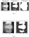
- Fig. 2 in effect shows the effects of applying a threshold.
- FIG. 2 there is a relatively clear distinction between an object (the phases, which are heated by Joule heating) and the background in the IRT image on the left.
- a threshold of about 42°C roughly reproduces the phases while removing the background (see middle image).
- the number of pixels above the threshold is 373 in this example. (This value is called the pixel count.)
- the lower threshold on the right has a higher pixel count - 768.
- the threshold used to obtain the "proper" middle image in Fig. 2 can be used to compute the temperature difference in the phase region.
- the temperature in the phases ranges from 42 to almost 50°C, so the temperature interval is 8K.
- a temperature interval need not be defined.
- a threshold temperature is determined by sorting all the pixels in descending order of temperature from a maximum temperature and a fixed number of pixels is chosen and the pixel that sits this fixed number in the sorted list of pixels from the maximum temperature defines a threshold temperature, and the difference between the maximum temperature and this threshold temperature provides the temperature interval.
- Fig. 4 which shows the same hot spot image as Fig. 3 , the pixels count (the number of pixels below the maximum temperature in the sorted list of pixels), and its associated threshold temperature, has been chosen such that the pixel count is as close to the value that fully shows all three phases.
- the image looks similar to the middle one in Fig. 2 , which shows a healthy image.
- the temperature interval is slightly larger (9K vs 8K). As the hot spot grows in intensity, so does the required interval, which goes up to 21K in Fig. 5 . Thus, the size of the interval can be used to classify faulty and healthy cases. If the temperature interval at the fixed pixel count is low, the temperature of the phases is homogeneous. If the interval is high, there is a hot spot.
- Fig. 6 shows a representation of how the fast variant inverse pixel count algorithm operates.
- An infrared image is shown at the top.
- the pixels have different temperatures.
- the pixels are sorted in decreasing temperatures, with the maximum temperature at the right hand side, which in this case is 32C.
- the infrared image only has 25 pixels, which is less than a real image and is being used for this example for simplicity.
- a number, in this case 4 is chosen.
- the temperature of the fourth pixel from the maximum temperature in the sorted list is identified. This is the temperature threshold, and in this case this is 31C.
- the temperature interval is 1C.
- the pixels are again ordered in decreasing temperatures, and the maximum temperature identified and the temperature of the fourth pixel down in the list identified, with the difference being the temperature interval. If this temperature interval suddenly increases, then a hot spot is developing and a warning can be indicated.
- the threshold temperature could be a fixed number such as 50, 100, 150, 200 etc. A determination of this number can be made by gradually selecting more of an image in terms of the hottest pixels until all of the relevant parts of the switchgear that are required to be monitored are selected. This number of pixels is then the number to be used in counting down from the hottest pixel in the sorted list of pixels to identify the threshold temperature in this image, which along with the maximum temperature provides the temperature interval. This same number is then used to count down in the list of sorted temperature pixels in subsequent infrared images to determine the temperature threshold for that image, which along with the maximum temperature for that image provides the temperature interval used to determine if there is a hot spot.
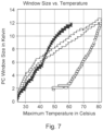
- the fast variant inverse pixel count algorithm can be used to distinguish faulty and healthy cases as can be seen in Fig. 7 .
- a simple algorithm would use a line to separate healthy and faulty above a temperature of 45°C, where every interval above the line would be classified as faulty and anything below as healthy.
- Fig. 7 it can be seen that above around 45C in one case of increasing maximum temperature the temperature interval diverges upwards, above the generally monotonically increasing case for a healthy switchgear, thereby indicating that there is a hotspot.
- More complex algorithms can apply different rules at different temperatures.
- the interval size can also be used as one of several machine learning features including for example maximum image temperature, and derivatives of the maximum temperature and derivatives of the temperature interval.
- a computer program or computer program element is provided that is characterized by being configured to execute the method steps of the method according to one of the preceding embodiments, on an appropriate processor or system.
- the computer program element might therefore be stored on a computer unit, which might also be part of an embodiment.
- This computing unit may be configured to perform or induce performing of the steps of the method described above. Moreover, it may be configured to operate the components of the above described system.
- the computing unit can be configured to operate automatically and/or to execute the orders of a user.
- a computer program may be loaded into a working memory of a data processor.
- the data processor may thus be equipped to carry out the method according to one of the preceding embodiments.
- This exemplary embodiment of the invention covers both, a computer program that right from the beginning uses the invention and computer program that by means of an update turns an existing program into a program that uses the invention.
- the computer program element might be able to provide all necessary steps to fulfill the procedure of an exemplary embodiment of the method as described above.
- a computer readable medium such as a CD-ROM, USB stick or the like
- the computer readable medium has a computer program element stored on it which computer program element is described by the preceding section.
- a computer program may be stored and/or distributed on a suitable medium, such as an optical storage medium or a solid state medium supplied together with or as part of other hardware, but may also be distributed in other forms, such as via the internet or other wired or wireless telecommunication systems.
- a suitable medium such as an optical storage medium or a solid state medium supplied together with or as part of other hardware, but may also be distributed in other forms, such as via the internet or other wired or wireless telecommunication systems.
- the computer program may also be presented over a network like the World Wide Web and can be downloaded into the working memory of a data processor from such a network.
- a medium for making a computer program element available for downloading is provided, which computer program element is arranged to perform a method according to one of the previously described embodiments of the invention.
Landscapes
- Engineering & Computer Science (AREA)
- Physics & Mathematics (AREA)
- General Physics & Mathematics (AREA)
- Theoretical Computer Science (AREA)
- Computer Vision & Pattern Recognition (AREA)
- Spectroscopy & Molecular Physics (AREA)
- Multimedia (AREA)
- Quality & Reliability (AREA)
- Radiation Pyrometers (AREA)
Abstract
Description
- The present invention relates to a system for monitoring a switchgear, a method for monitoring a switchgear, to a switchgear having such a system, and a computer program element.
- Electrical equipment such as switchgear can suffer from small faults that change the electrical resistance of the system. These faults manifest as hot spots and can ultimately lead to catastrophic failures. Here a switchgear can be a high voltage, medium voltage, or low voltage switchgear.
- One solution is to monitor parts of the switchgear, such as the phases, with an infrared thermographic camera to detect the hot spots. This is because infrared (IR) images can be used to identify technical problems within electrical equipment (e.g. switchgear) that lead to the overheating of components and to identify the hot spots themselves.
- However, while a human is quite capable of recognizing hot spots from infared images, monitoring 24 hours a day every day is required meaning that an automated system is required, and it is not simple for an automated system to determine from infrared imagery whether there is a hot spot.
- There is a need to address these issues.
- Therefore, it would be advantageous to have an improved system for monitoring a switch gear.
- The object of the present invention is solved with the subject matter of the independent claims, wherein further embodiments are incorporated in the dependent claims. It is to be noted that the system is described with respect to a switchgear, but finds utility in other electrical system than can suffer from components that overheat.
- In an aspect, there is provided a system for monitoring a switchgear. The system comprises:
- an infrared camera;
- a processing unit; and
- an output unit.
- The infrared camera is configured to acquire a first infrared image of the switchgear, and a total number of pixels in the first infrared image is equal to a first number. The processing unit is configured to determine a pixel in the first infrared image with a maximum temperature in the first infrared image. The processing unit is configured to utilize a second number of pixels less than the first number of pixels to determine a temperature interval for the first infrared image equal to a difference between the maximum temperature in the first infrared image and a threshold temperature in the first infrared image. The processing unit is configured to sort the pixels in the infrared image in descending order of temperature from the maximum temperature and determine the threshold temperature in the first infrared image as a temperature of a pixel in the first infrared image that is the pixel placed a set number in the sorted order of pixels in the descending order of temperature from the maximum temperature, and the set number is equal to the second number of pixels. The processing unit is configured to determine that a hot spot exists in the switchgear. The determination that the hot spot exists comprises utilization of the temperature interval for the first infrared image. The output unit is configured to output an indication of a fault in the switchgear when the determination has been made that a hot spot exists in the switchgear.
- In other words, infrared imagery of a switchgear is acquired, for example of the three phases. Each image could have 1024 pixels. A number such as 300 is selected. Then an image is analysed to determine the maximum or hottest temperature in an image. For example this could be 60.5C. Then the pixels are sorted in decreasing order of temperature. The pixel 300 from the maximum temperature in the descending list of pixel temperatures is identified. This for example could have a temperature of 51.5C. The temperature interval is then 60.5C minus 51.5C equal to 9C. And this temperature interval can be used to determine if there is a hot spot in the image.
- In other words, a temperature span of for example current carrying phases of a switchgear can indicate is there is a hotspot without requiring a detailed understanding of the image structure.
- In this manner, the new temperature monitoring system can be used to determine whether there are hot spots in the image that indicate faults in the switchgear system.
- Thus, for the above example the temperature interval of 9C can be associated with a correctly functioning switchgear with no hot spots. However, at a later time, if a hot spot develops the maximum temperature is again identified and the pixels are again sorted in descending order of temperature, and the pixel 300 from the top again identified and its temperature identified to determine a new temperature interval. If there is a hot spot, then the temperature interval will be greater than 9C and this can be used to determine that there is a hot spot.
- Also, a minimum amount of camera system configuration is required with respect to implementing such a switchgear monitoring system.
- According to an example, the second number is a predetermined number.
- According to an example, the second number is determined from one or more calibration infrared images of the, or a similar, switchgear.
- According to an example, the determination that the hot spot exists comprises utilization of the maximum temperature in the first infrared image.
- In this way, as the switchgear heats up a maximum temperature will gradually increase and for each maximum temperature it can be known what the temperature interval should be for a switchgear with no hot spots. Then, if for a maximum temperature the temperature interval is above that anticipated, it can be determined that there is a hot spot. Thus, it is not required to know whether the maximum temperature is normal or not, for example that would require to know at what time point in a heat-up stage the switchgear was, simply an indication that the temperature interval is above that anticipated for that maximum temperature is enough to indicate that there is a hotspot.
- According to an example, the determination that the hot spot exists comprises a determination that the temperature interval for the first infrared image is greater than a threshold temperature interval value.
- According to an example, the threshold temperature interval value is determined as a function of the maximum temperature in the first infrared image.
- According to an example, the infrared camera is configured to acquire a second infrared image of the switchgear after acquisition of the first infrared image of the switchgear, and a total number of pixels in the second infrared image is equal to the first number. The processing unit is configured to determine a pixel in the second infrared image with a maximum temperature in the second infrared image. The processing unit is configured to utilize the second number of pixels to determine a temperature interval for the second infrared image equal to a difference between the maximum temperature in the second infrared image and a threshold temperature in the second infrared image. The processing unit is configured to sort the pixels in the second infrared image in descending order of temperature from the maximum temperature in the second infrared image and determine the threshold temperature in the second infrared image as a temperature of a pixel in the second infrared image that is the pixel placed the set number in the sorted order of pixels in the descending order of temperature from the maximum temperature. The processing unit is configured to determine that the hot spot exists in the switchgear on the basis that the temperature interval for the second infrared image is greater than the temperature interval for the first infrared image.
- Thus for example, in operation in a steady state with constant current that should result in a constant maximum temperature or pseudo steady state with slight variations in current that can lead to variations in the maximum temperature, by monitoring the temperature interval between images it can be determined that there is a hotspot developing without. A hot spot can be identified and an alarm raised, whilst at the same time an increase in maximum temperature for a healthy system due to increased current can be identified as such because the temperature interval has either not increased or has not increased by a required amount to indicate that there is a hot spot.
- In an example, the processing unit is configured to determine that the hot spot exists in the switchgear on the basis that the temperature interval for the second infrared image is greater than the temperature interval for the first infrared image by a set amount.
- In an example, the set amount is 0,5C, 1C, 1.5C ... 3C.
- In an example, the set amount is determined as a function of the maximum temperature.
- According to an example, the infrared camera is configured to acquire a plurality of infrared images of the switchgear after acquisition of the first infrared image of the switchgear, and a total number of pixels in each of the plurality of infrared images is equal to the first number. The processing unit is configured to determine a pixel in each of plurality of infrareds image with a maximum temperature in the each of the plurality of infrared images. The processing unit is configured to utilize the second number of pixels to determine a temperature interval for each of the plurality of infrared images equal to a difference between the maximum temperature in the each of the plurality of infrared images and a threshold temperature in each of the plurality of infrared images. The processing unit is configured to sort the pixels in each of the plurality of infrared images in descending order of temperature from the maximum temperature in each of the plurality of infrared images and determine the threshold temperature in each of the plurality of infrared images as a temperature of a pixel in each of the plurality of infrared images that is the pixel placed the set number in the sorted order of pixels in the descending order of temperature from the maximum temperature. The processing unit is configured to determine that the hot spot exists in the switchgear on the basis of a rate of change between adjacent temperature intervals of the temperature interval for the first infrared image and the temperature intervals for the plurality of infrared images.
- According to an example, the determination that the hot spot exists comprises utilization of a machine learning algorithm
- According to an example, the machine learning algorithm is a trained neural network.
- According to an example, the system comprises a visible camera configured to acquire a visible image of the switchgear. The processing unit is configured to overlay a location of a maximum temperature in an infrared image onto a corresponding location in the visible image.
- According to an example, the processing unit is configured to overlay locations of pixels having a temperature between a threshold temperature and the maximum temperature in an infrared image onto corresponding locations in the visible image.
- In other words, the location of hot pixels can be mapped to a visible image in order to allow a human to review the situation to determine if there is a fault.
- In a second aspect, there is provided a switchgear comprising a system according to the first aspect.
- In a third aspect, there is provided a method for monitoring a switchgear. The method comprises:
- acquiring by an infrared camera a first infrared image of the switchgear, wherein a total number of pixels in the first infrared image is equal to a first number;
- determining by a processing unit a pixel in the first infrared image with a maximum temperature in the first infrared image;
- utilizing by the processing unit a second number of pixels less than the first number of pixels to determine a temperature interval for the first infrared image equal to a difference between the maximum temperature in the first infrared image and a threshold temperature in the first infrared image;
- sorting by the processing unit the pixels in the infrared image in descending order of temperature from the maximum temperature and determining the threshold temperature in the first infrared image as a temperature of a pixel in the first infrared image that is the pixel placed a set number in the sorted order of pixels in the descending order of temperature from the maximum temperature, and wherein the set number is equal to the second number of pixels;
- determining by the processing unit that a hot spot exists in the switchgear, wherein the determining that the hot spot exists comprises utilizing the temperature interval for the first infrared image; and
- outputting by an output unit an indication of a fault in the switchgear when the determination has been made that a hot spot exists in the switchgear.
- According to another aspect, there is provided a computer program element controlling one or more of the systems as previously described which, if the computer program element is executed by a processor, is adapted to perform the methods as previously described.
- According to another aspect, there is provided a computer readable medium having stored a computer element as previously described.
- The computer program element can for example be a software program but can also be a FPGA, a PLD or any other appropriate digital means.
- The above aspects and examples will become apparent from and be elucidated with reference to the embodiments described hereinafter.
- Exemplary embodiments will be described in the following with reference to the following drawings:
-
Fig. 1 shows an exemplar infrared image of a switchgear; -
Fig. 2 shows an exemplar infrared image of a switchgear and examples of two different thresholds being applied to the infrared image; -
Fig. 3 shows an exemplar infrared image of a switchgear with a hot spot and examples of the two different thresholds that were applied with respect toFig.2 now applied to the infrared image with the hot spot; and -
Fig. 4 shows the exemplar infrared image of a switchgear with a hot spot as shown inFig. 3 and an example of a threshold being applied that shows the three phases in a similar manner to the that shown inFig. 2 for a healthy switchgear; -
Fig. 5 shows the exemplar infrared image of a switchgear with a hot spot as shown inFig. 3 but that has increased in intensity and an example of a threshold being applied that shows the three phases in a similar manner to the that shown inFig. 2 for a healthy switchgear; -
Fig. 6 shows an example of pixels of an infrared image being sorted by temperature and the threshold temperature being determined; and -
Fig. 7 shows plots of maximum temperature against temperature interval for a healthy switchgear and for a switchgear with a developing hot spot. -
Figs. 1-7 provide details explaining a new system for monitoring a switchgear. The system comprises an infrared camera, a processing unit, and an output unit. The infrared camera is configured to acquire a first infrared image of the switchgear, and a total number of pixels in the first infrared image is equal to a first number. The processing unit is configured to determine a pixel in the first infrared image with a maximum temperature in the first infrared image. The processing unit is configured to utilize a second number of pixels less than the first number of pixels to determine a temperature interval for the first infrared image equal to a difference between the maximum temperature in the first infrared image and a threshold temperature in the first infrared image. The processing unit is configured to sort the pixels in the infrared image in descending order of temperature from the maximum temperature and determine the threshold temperature in the first infrared image as a temperature of a pixel in the first infrared image that is the pixel placed a set number in the sorted order of pixels in the descending order of temperature from the maximum temperature. The set number is equal to the second number of pixels. The processing unit is configured to determine that a hot spot exists in the switchgear. The determination that the hot spot exists comprises utilization of the temperature interval for the first infrared image. The output unit is configured to output an indication of a fault in the switchgear when the determination has been made that a hot spot exists in the switchgear. - In an example, the second number is determined from an infrared image captured by the infrared camera, or an equivalent infrared camera, of the switchgear, or an equivalent switchgear, such that the second number is a number of pixels in the infrared image that have the highest temperature values and that cover the parts of the switchgear, such as the phases or parts of the phases, that are required to be monitored. In other words, a correctly functioning switchgear can be imaged and the number of the hottest pixels varied until the associated parts of the image cover the parts of the switchgear required to be monitored. This then sets the second number (say X), and is then used to identify the hottest X pixels in subsequent images and the temperature threshold which along with the maximum temperature provides the associated temperature interval that is used to indicate if there is a hot spot or not.
- According to an example, the second number is a predetermined number.
- According to an example, the second number is determined from one or more calibration infrared images of the, or a similar, switchgear.
- According to an example, the determination that the hot spot exists comprises utilization of the maximum temperature in the first infrared image.
- According to an example, the determination that the hot spot exists comprises a determination that the temperature interval for the first infrared image is greater than a threshold temperature interval value.
- According to an example, the threshold temperature interval value is determined as a function of the maximum temperature in the first infrared image.
- According to an example, the infrared camera is configured to acquire a second infrared image of the switchgear after acquisition of the first infrared image of the switchgear, and a total number of pixels in the second infrared image is equal to the first number. The processing unit is configured to determine a pixel in the second infrared image with a maximum temperature in the second infrared image. The processing unit is configured to utilize the second number of pixels to determine a temperature interval for the second infrared image equal to a difference between the maximum temperature in the second infrared image and a threshold temperature in the second infrared image. The processing unit is configured to sort the pixels in the second infrared image in descending order of temperature from the maximum temperature in the second infrared image and determine the threshold temperature in the second infrared image as a temperature of a pixel in the second infrared image that is the pixel placed the set number in the sorted order of pixels in the descending order of temperature from the maximum temperature. The processing unit is configured to determine that the hot spot exists in the switchgear on the basis that the temperature interval for the second infrared image is greater than the temperature interval for the first infrared image.
- In an example, the processing unit is configured to determine that the hot spot exists in the switchgear on the basis that the temperature interval for the second infrared image is greater than the temperature interval for the first infrared image by a set amount.
- In an example, the set amount is 0,5C, 1C, 1.5C ... 3C.
- In an example, the set amount is determined as a function of the maximum temperature.
- According to an example, the infrared camera is configured to acquire a plurality of infrared images of the switchgear after acquisition of the first infrared image of the switchgear, and a total number of pixels in each of the plurality of infrared images is equal to the first number. The processing unit is configured to determine a pixel in each of plurality of infrareds image with a maximum temperature in the each of the plurality of infrared images. The processing unit is configured to utilize the second number of pixels to determine a temperature interval for each of the plurality of infrared images equal to a difference between the maximum temperature in the each of the plurality of infrared images and a threshold temperature in each of the plurality of infrared images. The processing unit is configured to sort the pixels in each of the plurality of infrared images in descending order of temperature from the maximum temperature in each of the plurality of infrared images and determine the threshold temperature in each of the plurality of infrared images as a temperature of a pixel in each of the plurality of infrared images that is the pixel placed the set number in the sorted order of pixels in the descending order of temperature from the maximum temperature. The processing unit is configured to determine that the hot spot exists in the switchgear on the basis of a rate of change between adjacent temperature intervals of the temperature interval for the first infrared image and the temperature intervals for the plurality of infrared images.
- According to an example, the determination that the hot spot exists comprises utilization of a machine learning algorithm
- According to an example, the machine learning algorithm is a trained neural network.
- According to an example, the system comprises a visible camera configured to acquire a visible image of the switchgear. The processing unit is configured to overlay a location of a maximum temperature in an infrared image onto a corresponding location in the visible image.
- According to an example, the processing unit is configured to overlay locations of pixels having a temperature between a threshold temperature and the maximum temperature in an infrared image onto corresponding locations in the visible image.
- It is clear from the above a switchgear can comprising such a system as described above, whether retrofitted to an existing switchgear, or provided with a switchgear as it is built.
- Also, it is clear that an associated method for monitoring a switchgear comprises:
- acquiring by an infrared camera a first infrared image of the switchgear, wherein a total number of pixels in the first infrared image is equal to a first number;
- determining by a processing unit a pixel in the first infrared image with a maximum temperature in the first infrared image;
- utilizing by the processing unit a second number of pixels less than the first number of pixels to determine a temperature interval for the first infrared image equal to a difference between the maximum temperature in the first infrared image and a threshold temperature in the first infrared image;
- sorting by the processing unit the pixels in the infrared image in descending order of temperature from the maximum temperature and determining the threshold temperature in the first infrared image as a temperature of a pixel in the first infrared image that is the pixel placed a set number in the sorted order of pixels in the descending order of temperature from the maximum temperature, and wherein the set number is equal to the second number of pixels;
- determining by the processing unit that a hot spot exists in the switchgear, wherein the determining that the hot spot exists comprises utilizing the temperature interval for the first infrared image; and
- outputting by an output unit an indication of a fault in the switchgear when the determination has been made that a hot spot exists in the switchgear.
- In an example, the second number is a predetermined number.
- In an example, the second number is determined from one or more calibration infrared images of the, or a similar, switchgear.
- In an example, the determining that the hot spot exists comprises utilizing the maximum temperature in the first infrared image.
- In an example, the determining that the hot spot exists comprises determining that the temperature interval for the first infrared image is greater than a threshold temperature interval value.
- In an example, the threshold temperature interval value is determined as a function of the maximum temperature in the first infrared image.
- In an example, the method comprises:
- acquiring by the infrared camera a second infrared image of the switchgear after acquisition of the first infrared image of the switchgear, wherein a total number of pixels in the second infrared image is equal to the first number;
- determining by the processing unit a pixel in the second infrared image with a maximum temperature in the second infrared image;
- utilizing by the processing unit the second number of pixels to determine a temperature interval for the second infrared image equal to a difference between the maximum temperature in the second infrared image and a threshold temperature in the second infrared image;
- sorting by the processing unit the pixels in the second infrared image in descending order of temperature from the maximum temperature in the second infrared image and determining the threshold temperature in the second infrared image as a temperature of a pixel in the second infrared image that is the pixel placed the set number in the sorted order of pixels in the descending order of temperature from the maximum temperature; and
- determining by the processing unit that the hot spot exists in the switchgear on the basis that the temperature interval for the second infrared image is greater than the temperature interval for the first infrared image.
- In an example, method comprises:
- acquiring by the infrared camera a plurality infrared images of the switchgear after acquisition of the first infrared image of the switchgear, wherein a total number of pixels in each of the plurality of infrared images is equal to the first number;
- determining by the processing unit a pixel in each of plurality of infrareds image with a maximum temperature in the each of the plurality of infrared images;
- utilizing by the processing unit the second number of pixels to determine a temperature interval for each of the plurality of infrared images equal to a difference between the maximum temperature in the each of the plurality of infrared images and a threshold temperature in each of the plurality of infrared images;
- sorting by the processing unit the pixels in each of the plurality of infrared images in descending order of temperature from the maximum temperature in each of the plurality of infrared images and determining the threshold temperature in each of the plurality of infrared images as a temperature of a pixel in each of the plurality of infrared images that is the pixel placed the set number in the sorted order of pixels in the descending order of temperature from the maximum temperature;
- determining by the processing unit that the hot spot exists in the switchgear on the basis of a rate of change between adjacent temperature intervals of the temperature interval for the first infrared image and the temperature intervals for the plurality of infrared images.
- In an example, the determining that the hot spot exists comprises utilizing a machine learning algorithm.
- In an example, the machine learning algorithm is a trained neural network.
- In an example, the method comprises acquiring by a visible camera a visible image of the switchgear, and overlaying by the processing unit a location of a maximum temperature in an infrared image onto a corresponding location in the visible image.
- In an example, the method comprises overlaying by the processing unit locations of pixels having a temperature between a threshold temperature and the maximum temperature in an infrared image onto corresponding locations in the visible image.
- Continuing with the figures, the system and method for monitoring a switchgear is described in further detail, with respect to specific embodiments.
- It is to be noted, that the basis for the new system and method for monitoring a switchgear is based around a new algorithm that is termed an fast variant inverse pixel count algorithm.
- An infrared thermographic (IRT) image is essentially a matrix of temperature values or a grayscale image. An example is shown in
Fig. 1 . The image shows the phases of a medium-voltage switchgear which heat up because current is flowing through them. The same applies to a high-voltage switchgear and to a low-voltage switchgear. - By applying a threshold to the image, the image can be separated into two regions - a region where the temperature is above the threshold (t) and the region where it is below t. In
Fig. 2 , an IRT image from another switchgear compartment is shown where the maximum temperature is about 50°C. The image in the middle shows the result of applying a threshold of 42°C. All pixels hotter than or as hot as that are marked white, anything else is marked black. In the image on the right, a threshold of 35°C is used. The lower the threshold, the more pixels will be included. ThusFig. 2 in effect shows the effects of applying a threshold. - In the example of
Fig. 2 , there is a relatively clear distinction between an object (the phases, which are heated by Joule heating) and the background in the IRT image on the left. A threshold of about 42°C (ca 8K below the maximum temperature) roughly reproduces the phases while removing the background (see middle image). When the phase is fully visible, the number of pixels above the threshold is 373 in this example. (This value is called the pixel count.) The lower threshold on the right has a higher pixel count - 768. - The threshold used to obtain the "proper" middle image in
Fig. 2 can be used to compute the temperature difference in the phase region. In the example, the temperature in the phases ranges from 42 to almost 50°C, so the temperature interval is 8K. - When the same thresholds are applied to an image with a hot spot but roughly the same maximum temperature (
Fig. 3 , left), the pixel count will be lower for an image with the same maximum temperature and the same threshold levels. The reason is that a bigger temperature interval would be needed to include all phases because the hot spot by definition has a higher temperature than the other phases. In other words as a hot spot spike in temperature starts to occur this maximum temperature becomes more separated from the temperatures of the other parts of the switchgear such that the number of pixels within a fixed threshold of the maximum become ever smaller as the hot spot increases in temperature. If for the same maximum temperature and the same temperature interval the pixel count is lower, there is a hot spot. - However, it was realised that for the new system a temperature interval need not be defined. Thus in the new fast variant inverse pixel count algorithm there is no definition of a temperature interval and a counting of the pixels. Rather in the fast variant inverse pixel count algorithm a threshold temperature is determined by sorting all the pixels in descending order of temperature from a maximum temperature and a fixed number of pixels is chosen and the pixel that sits this fixed number in the sorted list of pixels from the maximum temperature defines a threshold temperature, and the difference between the maximum temperature and this threshold temperature provides the temperature interval.
- In
Fig. 4 , which shows the same hot spot image asFig. 3 , the pixels count (the number of pixels below the maximum temperature in the sorted list of pixels), and its associated threshold temperature, has been chosen such that the pixel count is as close to the value that fully shows all three phases. The image looks similar to the middle one inFig. 2 , which shows a healthy image. - The main difference, however, is that the temperature interval is slightly larger (9K vs 8K). As the hot spot grows in intensity, so does the required interval, which goes up to 21K in
Fig. 5 . Thus, the size of the interval can be used to classify faulty and healthy cases. If the temperature interval at the fixed pixel count is low, the temperature of the phases is homogeneous. If the interval is high, there is a hot spot. -
Fig. 6 shows a representation of how the fast variant inverse pixel count algorithm operates. An infrared image is shown at the top. The pixels have different temperatures. The pixels are sorted in decreasing temperatures, with the maximum temperature at the right hand side, which in this case is 32C. In this example case the infrared image only has 25 pixels, which is less than a real image and is being used for this example for simplicity. A number, in thiscase 4, is chosen. The temperature of the fourth pixel from the maximum temperature in the sorted list is identified. This is the temperature threshold, and in this case this is 31C. Then the temperature interval is 1C. For all subsequent images, the pixels are again ordered in decreasing temperatures, and the maximum temperature identified and the temperature of the fourth pixel down in the list identified, with the difference being the temperature interval. If this temperature interval suddenly increases, then a hot spot is developing and a warning can be indicated. - In the above example, there were only 25 pixels and the fourth pixel down from the maximum in the sorted list was used to determine the threshold temperature. In a real infrared image with for example 1024 pixels, the threshold temperature could be a fixed number such as 50, 100, 150, 200 etc. A determination of this number can be made by gradually selecting more of an image in terms of the hottest pixels until all of the relevant parts of the switchgear that are required to be monitored are selected. This number of pixels is then the number to be used in counting down from the hottest pixel in the sorted list of pixels to identify the threshold temperature in this image, which along with the maximum temperature provides the temperature interval. This same number is then used to count down in the list of sorted temperature pixels in subsequent infrared images to determine the temperature threshold for that image, which along with the maximum temperature for that image provides the temperature interval used to determine if there is a hot spot.
- The fast variant inverse pixel count algorithm can be used to distinguish faulty and healthy cases as can be seen in
Fig. 7 . A simple algorithm would use a line to separate healthy and faulty above a temperature of 45°C, where every interval above the line would be classified as faulty and anything below as healthy. InFig. 7 it can be seen that above around 45C in one case of increasing maximum temperature the temperature interval diverges upwards, above the generally monotonically increasing case for a healthy switchgear, thereby indicating that there is a hotspot. More complex algorithms can apply different rules at different temperatures. The interval size can also be used as one of several machine learning features including for example maximum image temperature, and derivatives of the maximum temperature and derivatives of the temperature interval. - In another exemplary embodiment, a computer program or computer program element is provided that is characterized by being configured to execute the method steps of the method according to one of the preceding embodiments, on an appropriate processor or system.
- The computer program element might therefore be stored on a computer unit, which might also be part of an embodiment. This computing unit may be configured to perform or induce performing of the steps of the method described above. Moreover, it may be configured to operate the components of the above described system. The computing unit can be configured to operate automatically and/or to execute the orders of a user. A computer program may be loaded into a working memory of a data processor. The data processor may thus be equipped to carry out the method according to one of the preceding embodiments.
- This exemplary embodiment of the invention covers both, a computer program that right from the beginning uses the invention and computer program that by means of an update turns an existing program into a program that uses the invention.
- Further on, the computer program element might be able to provide all necessary steps to fulfill the procedure of an exemplary embodiment of the method as described above.
- According to a further exemplary embodiment of the present invention, a computer readable medium, such as a CD-ROM, USB stick or the like, is presented wherein the computer readable medium has a computer program element stored on it which computer program element is described by the preceding section.
- A computer program may be stored and/or distributed on a suitable medium, such as an optical storage medium or a solid state medium supplied together with or as part of other hardware, but may also be distributed in other forms, such as via the internet or other wired or wireless telecommunication systems.
- However, the computer program may also be presented over a network like the World Wide Web and can be downloaded into the working memory of a data processor from such a network. According to a further exemplary embodiment of the present invention, a medium for making a computer program element available for downloading is provided, which computer program element is arranged to perform a method according to one of the previously described embodiments of the invention.
Claims (15)
- A system for monitoring a switchgear, the system comprising:- an infrared camera;- a processing unit; and- an output unit;wherein the infrared camera is configured to acquire a first infrared image of the switchgear, wherein a total number of pixels in the first infrared image is equal to a first number;wherein the processing unit is configured to determine a pixel in the first infrared image with a maximum temperature in the first infrared image;wherein the processing unit is configured to utilize a second number of pixels less than the first number of pixels to determine a temperature interval for the first infrared image equal to a difference between the maximum temperature in the first infrared image and a threshold temperature in the first infrared image;wherein the processing unit is configured to sort the pixels in the infrared image in descending order of temperature from the maximum temperature and determine the threshold temperature in the first infrared image as a temperature of a pixel in the first infrared image that is the pixel placed a set number in the sorted order of pixels in the descending order of temperature from the maximum temperature, and wherein the set number is equal to the second number of pixels;wherein the processing unit is configured to determine that a hot spot exists in the switchgear, wherein the determination that the hot spot exists comprises utilization of the temperature interval for the first infrared image; andwherein the output unit is configured to output an indication of a fault in the switchgear when the determination has been made that a hot spot exists in the switchgear.
- System according to claim 1, wherein the second number is a predetermined number.
- System according to any of claims 1-2, wherein the second number is determined from one or more calibration infrared images of the, or a similar, switchgear.
- System according to any of claims 1-3, wherein the determination that the hot spot exists comprises utilization of the maximum temperature in the first infrared image.
- System according to any of claims 1-4, wherein the determination that the hot spot exists comprises a determination that the temperature interval for the first infrared image is greater than a threshold temperature interval value.
- System according to claim 5, wherein the threshold temperature interval value is determined as a function of the maximum temperature in the first infrared image.
- System according to any of claims 1-6, wherein the infrared camera is configured to acquire a second infrared image of the switchgear after acquisition of the first infrared image of the switchgear, wherein a total number of pixels in the second infrared image is equal to the first number, wherein the processing unit is configured to determine a pixel in the second infrared image with a maximum temperature in the second infrared image, wherein the processing unit is configured to utilize the second number of pixels to determine a temperature interval for the second infrared image equal to a difference between the maximum temperature in the second infrared image and a threshold temperature in the second infrared image, wherein the processing unit is configured to sort the pixels in the second infrared image in descending order of temperature from the maximum temperature in the second infrared image and determine the threshold temperature in the second infrared image as a temperature of a pixel in the second infrared image that is the pixel placed the set number in the sorted order of pixels in the descending order of temperature from the maximum temperature, wherein the processing unit is configured to determine that the hot spot exists in the switchgear on the basis that the temperature interval for the second infrared image is greater than the temperature interval for the first infrared image.
- System according to any of claims 1-7, wherein the infrared camera is configured to acquire a plurality infrared images of the switchgear after acquisition of the first infrared image of the switchgear, wherein a total number of pixels in each of the plurality of infrared images is equal to the first number, wherein the processing unit is configured to determine a pixel in each of plurality of infrareds image with a maximum temperature in the each of the plurality of infrared images, wherein the processing unit is configured to utilize the second number of pixels to determine a temperature interval for each of the plurality of infrared images equal to a difference between the maximum temperature in the each of the plurality of infrared images and a threshold temperature in each of the plurality of infrared images, wherein the processing unit is configured to sort the pixels in each of the plurality of infrared images in descending order of temperature from the maximum temperature in each of the plurality of infrared images and determine the threshold temperature in each of the plurality of infrared images as a temperature of a pixel in each of the plurality of infrared images that is the pixel placed the set number in the sorted order of pixels in the descending order of temperature from the maximum temperature, wherein the processing unit is configured to determine that the hot spot exists in the switchgear on the basis of a rate of change between adjacent temperature intervals of the temperature interval for the first infrared image and the temperature intervals for the plurality of infrared images.
- System according to any of claims 1-8, wherein the determination that the hot spot exists comprises utilization of a machine learning algorithm
- System according to claim 9, wherein the machine learning algorithm is a trained neural network.
- System according to any of claims 1-10, wherein the system comprises a visible camera configured to acquire a visible image of the switchgear, and wherein the processing unit is configured to overlay a location of a maximum temperature in an infrared image onto a corresponding location in the visible image.
- System according to claim 11, wherein the processing unit is configured to overlay locations of pixels having a temperature between a threshold temperature and the maximum temperature in an infrared image onto corresponding locations in the visible image.
- A switchgear comprising a system according to any of claims 1-12.
- A method for monitoring a switchgear, the method comprising:- acquiring by an infrared camera a first infrared image of the switchgear, wherein a total number of pixels in the first infrared image is equal to a first number;- determining by a processing unit a pixel in the first infrared image with a maximum temperature in the first infrared image;- utilizing by the processing unit a second number of pixels less than the first number of pixels to determine a temperature interval for the first infrared image equal to a difference between the maximum temperature in the first infrared image and a threshold temperature in the first infrared image;- sorting by the processing unit the pixels in the infrared image in descending order of temperature from the maximum temperature and determining the threshold temperature in the first infrared image as a temperature of a pixel in the first infrared image that is the pixel placed a set number in the sorted order of pixels in the descending order of temperature from the maximum temperature, and wherein the set number is equal to the second number of pixels;- determining by the processing unit that a hot spot exists in the switchgear, wherein the determining that the hot spot exists comprises utilizing the temperature interval for the first infrared image; and- outputting by an output unit an indication of a fault in the switchgear when the determination has been made that a hot spot exists in the switchgear.
- A computer program element for controlling an system according to any of claims 1-13 which when executed by a processor is configured to carry out the method of claim 14.
Priority Applications (4)
| Application Number | Priority Date | Filing Date | Title |
|---|---|---|---|
| ES22169229T ES3057391T3 (en) | 2022-04-21 | 2022-04-21 | System for monitoring a switchgear |
| EP22169229.6A EP4266015B1 (en) | 2022-04-21 | 2022-04-21 | System for monitoring a switchgear |
| US18/303,645 US12548139B2 (en) | 2022-04-21 | 2023-04-20 | System for monitoring a switchgear |
| CN202310431892.XA CN116930732A (en) | 2022-04-21 | 2023-04-21 | Systems for monitoring switchgear |
Applications Claiming Priority (1)
| Application Number | Priority Date | Filing Date | Title |
|---|---|---|---|
| EP22169229.6A EP4266015B1 (en) | 2022-04-21 | 2022-04-21 | System for monitoring a switchgear |
Publications (2)
| Publication Number | Publication Date |
|---|---|
| EP4266015A1 true EP4266015A1 (en) | 2023-10-25 |
| EP4266015B1 EP4266015B1 (en) | 2025-10-01 |
Family
ID=81345928
Family Applications (1)
| Application Number | Title | Priority Date | Filing Date |
|---|---|---|---|
| EP22169229.6A Active EP4266015B1 (en) | 2022-04-21 | 2022-04-21 | System for monitoring a switchgear |
Country Status (4)
| Country | Link |
|---|---|
| US (1) | US12548139B2 (en) |
| EP (1) | EP4266015B1 (en) |
| CN (1) | CN116930732A (en) |
| ES (1) | ES3057391T3 (en) |
Families Citing this family (2)
| Publication number | Priority date | Publication date | Assignee | Title |
|---|---|---|---|---|
| EP4120490B1 (en) * | 2021-07-14 | 2025-12-31 | Abb Schweiz Ag | SYSTEM FOR MONITORING A DEVICE |
| US11927485B2 (en) * | 2021-12-17 | 2024-03-12 | Rebellion Photonics, Inc. | Systems, methods, and computer program products for detection limit determinations for hyperspectral imaging |
Citations (3)
| Publication number | Priority date | Publication date | Assignee | Title |
|---|---|---|---|---|
| EP3716205A1 (en) * | 2019-03-26 | 2020-09-30 | ABB Schweiz AG | An apparatus for hot spot sensing |
| EP3786598A1 (en) * | 2019-08-30 | 2021-03-03 | ABB Schweiz AG | System for monitoring a switchgear |
| KR102295188B1 (en) * | 2021-02-18 | 2021-08-31 | 주식회사 삼광산전 | Artificial intelligence switchboard having integrated anomaly monitoring and defect prediction function |
Family Cites Families (4)
| Publication number | Priority date | Publication date | Assignee | Title |
|---|---|---|---|---|
| US8462990B2 (en) * | 2008-10-21 | 2013-06-11 | West Nippon Expressway Engineering Shikoku Company Limited | Infrared-ray thermal image analyzer |
| WO2017177370A1 (en) * | 2016-04-12 | 2017-10-19 | 深圳华盛昌机械实业有限公司 | Image fusion method and apparatus, and infrared thermography device |
| EP4080450B1 (en) * | 2021-04-20 | 2025-06-04 | ABB Schweiz AG | A system for monitoring a device |
| EP4212838B1 (en) * | 2022-01-14 | 2025-11-12 | Abb Schweiz Ag | System for monitoring a switchgear |
-
2022
- 2022-04-21 EP EP22169229.6A patent/EP4266015B1/en active Active
- 2022-04-21 ES ES22169229T patent/ES3057391T3/en active Active
-
2023
- 2023-04-20 US US18/303,645 patent/US12548139B2/en active Active
- 2023-04-21 CN CN202310431892.XA patent/CN116930732A/en active Pending
Patent Citations (3)
| Publication number | Priority date | Publication date | Assignee | Title |
|---|---|---|---|---|
| EP3716205A1 (en) * | 2019-03-26 | 2020-09-30 | ABB Schweiz AG | An apparatus for hot spot sensing |
| EP3786598A1 (en) * | 2019-08-30 | 2021-03-03 | ABB Schweiz AG | System for monitoring a switchgear |
| KR102295188B1 (en) * | 2021-02-18 | 2021-08-31 | 주식회사 삼광산전 | Artificial intelligence switchboard having integrated anomaly monitoring and defect prediction function |
Non-Patent Citations (2)
| Title |
|---|
| GITZEL RALF ET AL: "AUTOMATIC ANALYSIS OF THERMOGRAMS - CHALLENGE IN THERMAL MONITORING OF SWITCHGEARS USING INFRARED CAMERAS", 20 September 2021 (2021-09-20), pages 395 - 399, XP055931303, ISBN: 978-1-83953-591-8, Retrieved from the Internet <URL:https://ieeexplore.ieee.org/stampPDF/getPDF.jsp?tp=&arnumber=9692744&ref=aHR0cHM6Ly9pZWVleHBsb3JlLmllZWUub3JnL2RvY3VtZW50Lzk2OTI3NDQ=> DOI: 10.1049/icp.2021.1581 * |
| YAN YUNFENG ET AL: "A Real-Time IR-Fusion Switchgear Contact Monitoring System (SCMS)", IEEE ACCESS, vol. 5, 25 May 2017 (2017-05-25), pages 12114 - 12124, XP011657088, DOI: 10.1109/ACCESS.2017.2698060 * |
Also Published As
| Publication number | Publication date |
|---|---|
| ES3057391T3 (en) | 2026-03-02 |
| US20230342906A1 (en) | 2023-10-26 |
| CN116930732A (en) | 2023-10-24 |
| EP4266015B1 (en) | 2025-10-01 |
| US12548139B2 (en) | 2026-02-10 |
Similar Documents
| Publication | Publication Date | Title |
|---|---|---|
| US12625003B2 (en) | System for monitoring a switchgear | |
| US12548139B2 (en) | System for monitoring a switchgear | |
| US11694320B2 (en) | System for monitoring a switchgear | |
| Jadin et al. | Feature extraction and classification for detecting the thermal faults in electrical installations | |
| CN115219039B (en) | Systems for monitoring equipment | |
| US12092526B2 (en) | Apparatus for monitoring a switchgear | |
| CN117613822B (en) | Method, device, equipment and storage medium for fast shutdown of frequency converter | |
| EP4235591A1 (en) | System for monitoring a switchgear | |
| KR102610309B1 (en) | System for performing thermal imaging monitoring and diagnosis based on artificial intelligence | |
| EP4414725A1 (en) | System for monitoring a switchgear | |
| EP4403937B1 (en) | System for monitoring a switchgear | |
| EP4414674B1 (en) | System, method, and computer program element for monitoring a switchgear | |
| CN118967684A (en) | Power equipment detection method and system based on image recognition | |
| CN113544923B (en) | Devices for monitoring switchgear | |
| CN118483562A (en) | System for monitoring a switching device | |
| US20250198848A1 (en) | Device and method for electrical fault detection | |
| EP4411665A1 (en) | Switchgear monitoring apparatus | |
| Malek et al. | Condition based monitoring of gapless surge arrester using electrical and thermal parameters | |
| EP3706266A1 (en) | Artificial intelligence monitoring system using infrared images to identify hotspots in a switchgear |
Legal Events
| Date | Code | Title | Description |
|---|---|---|---|
| STAA | Information on the status of an ep patent application or granted ep patent |
Free format text: STATUS: THE APPLICATION HAS BEEN PUBLISHED |
|
| PUAI | Public reference made under article 153(3) epc to a published international application that has entered the european phase |
Free format text: ORIGINAL CODE: 0009012 |
|
| AK | Designated contracting states |
Kind code of ref document: A1 Designated state(s): AL AT BE BG CH CY CZ DE DK EE ES FI FR GB GR HR HU IE IS IT LI LT LU LV MC MK MT NL NO PL PT RO RS SE SI SK SM TR |
|
| STAA | Information on the status of an ep patent application or granted ep patent |
Free format text: STATUS: REQUEST FOR EXAMINATION WAS MADE |
|
| 17P | Request for examination filed |
Effective date: 20240312 |
|
| RBV | Designated contracting states (corrected) |
Designated state(s): AL AT BE BG CH CY CZ DE DK EE ES FI FR GB GR HR HU IE IS IT LI LT LU LV MC MK MT NL NO PL PT RO RS SE SI SK SM TR |
|
| REG | Reference to a national code |
Ref country code: DE Ref legal event code: R079 Free format text: PREVIOUS MAIN CLASS: G01J0005000000 Ipc: G06V0010560000 Ref country code: DE Ref legal event code: R079 Ref document number: 602022022135 Country of ref document: DE Free format text: PREVIOUS MAIN CLASS: G01J0005000000 Ipc: G06V0010560000 |
|
| GRAP | Despatch of communication of intention to grant a patent |
Free format text: ORIGINAL CODE: EPIDOSNIGR1 |
|
| STAA | Information on the status of an ep patent application or granted ep patent |
Free format text: STATUS: GRANT OF PATENT IS INTENDED |
|
| RIC1 | Information provided on ipc code assigned before grant |
Ipc: G06T 7/11 20170101ALI20250516BHEP Ipc: G06T 7/00 20170101ALI20250516BHEP Ipc: G06T 7/136 20170101ALI20250516BHEP Ipc: G01J 5/48 20220101ALI20250516BHEP Ipc: H02B 13/065 20060101ALI20250516BHEP Ipc: G01J 5/00 20220101ALI20250516BHEP Ipc: G06V 20/52 20220101ALI20250516BHEP Ipc: G06V 10/56 20220101AFI20250516BHEP |
|
| INTG | Intention to grant announced |
Effective date: 20250528 |
|
| GRAS | Grant fee paid |
Free format text: ORIGINAL CODE: EPIDOSNIGR3 |
|
| GRAA | (expected) grant |
Free format text: ORIGINAL CODE: 0009210 |
|
| STAA | Information on the status of an ep patent application or granted ep patent |
Free format text: STATUS: THE PATENT HAS BEEN GRANTED |
|
| AK | Designated contracting states |
Kind code of ref document: B1 Designated state(s): AL AT BE BG CH CY CZ DE DK EE ES FI FR GB GR HR HU IE IS IT LI LT LU LV MC MK MT NL NO PL PT RO RS SE SI SK SM TR |
|
| REG | Reference to a national code |
Ref country code: GB Ref legal event code: FG4D Ref country code: CH Ref legal event code: F10 Free format text: ST27 STATUS EVENT CODE: U-0-0-F10-F00 (AS PROVIDED BY THE NATIONAL OFFICE) Effective date: 20251001 |
|
| REG | Reference to a national code |
Ref country code: IE Ref legal event code: FG4D |
|
| REG | Reference to a national code |
Ref country code: DE Ref legal event code: R096 Ref document number: 602022022135 Country of ref document: DE |
|
| REG | Reference to a national code |
Ref country code: NL Ref legal event code: MP Effective date: 20251001 |
|
| REG | Reference to a national code |
Ref country code: ES Ref legal event code: FG2A Ref document number: 3057391 Country of ref document: ES Kind code of ref document: T3 Effective date: 20260302 |
|
| REG | Reference to a national code |
Ref country code: AT Ref legal event code: MK05 Ref document number: 1843322 Country of ref document: AT Kind code of ref document: T Effective date: 20251001 |
|
| PG25 | Lapsed in a contracting state [announced via postgrant information from national office to epo] |
Ref country code: NL Free format text: LAPSE BECAUSE OF FAILURE TO SUBMIT A TRANSLATION OF THE DESCRIPTION OR TO PAY THE FEE WITHIN THE PRESCRIBED TIME-LIMIT Effective date: 20251001 |
|
| REG | Reference to a national code |
Ref country code: LT Ref legal event code: MG9D |
|
| PG25 | Lapsed in a contracting state [announced via postgrant information from national office to epo] |
Ref country code: NO Free format text: LAPSE BECAUSE OF FAILURE TO SUBMIT A TRANSLATION OF THE DESCRIPTION OR TO PAY THE FEE WITHIN THE PRESCRIBED TIME-LIMIT Effective date: 20260101 |
|
| PG25 | Lapsed in a contracting state [announced via postgrant information from national office to epo] |
Ref country code: HR Free format text: LAPSE BECAUSE OF FAILURE TO SUBMIT A TRANSLATION OF THE DESCRIPTION OR TO PAY THE FEE WITHIN THE PRESCRIBED TIME-LIMIT Effective date: 20251001 Ref country code: FI Free format text: LAPSE BECAUSE OF FAILURE TO SUBMIT A TRANSLATION OF THE DESCRIPTION OR TO PAY THE FEE WITHIN THE PRESCRIBED TIME-LIMIT Effective date: 20251001 Ref country code: AT Free format text: LAPSE BECAUSE OF FAILURE TO SUBMIT A TRANSLATION OF THE DESCRIPTION OR TO PAY THE FEE WITHIN THE PRESCRIBED TIME-LIMIT Effective date: 20251001 |
|
| PG25 | Lapsed in a contracting state [announced via postgrant information from national office to epo] |
Ref country code: RS Free format text: LAPSE BECAUSE OF FAILURE TO SUBMIT A TRANSLATION OF THE DESCRIPTION OR TO PAY THE FEE WITHIN THE PRESCRIBED TIME-LIMIT Effective date: 20260101 |
|
| PG25 | Lapsed in a contracting state [announced via postgrant information from national office to epo] |
Ref country code: IS Free format text: LAPSE BECAUSE OF FAILURE TO SUBMIT A TRANSLATION OF THE DESCRIPTION OR TO PAY THE FEE WITHIN THE PRESCRIBED TIME-LIMIT Effective date: 20260201 |
|
| PG25 | Lapsed in a contracting state [announced via postgrant information from national office to epo] |
Ref country code: CZ Free format text: LAPSE BECAUSE OF FAILURE TO SUBMIT A TRANSLATION OF THE DESCRIPTION OR TO PAY THE FEE WITHIN THE PRESCRIBED TIME-LIMIT Effective date: 20251001 Ref country code: PT Free format text: LAPSE BECAUSE OF FAILURE TO SUBMIT A TRANSLATION OF THE DESCRIPTION OR TO PAY THE FEE WITHIN THE PRESCRIBED TIME-LIMIT Effective date: 20260202 |
|
| PG25 | Lapsed in a contracting state [announced via postgrant information from national office to epo] |
Ref country code: PL Free format text: LAPSE BECAUSE OF FAILURE TO SUBMIT A TRANSLATION OF THE DESCRIPTION OR TO PAY THE FEE WITHIN THE PRESCRIBED TIME-LIMIT Effective date: 20251001 |
|
| PG25 | Lapsed in a contracting state [announced via postgrant information from national office to epo] |
Ref country code: LV Free format text: LAPSE BECAUSE OF FAILURE TO SUBMIT A TRANSLATION OF THE DESCRIPTION OR TO PAY THE FEE WITHIN THE PRESCRIBED TIME-LIMIT Effective date: 20251001 |
|
| PG25 | Lapsed in a contracting state [announced via postgrant information from national office to epo] |
Ref country code: BG Free format text: LAPSE BECAUSE OF FAILURE TO SUBMIT A TRANSLATION OF THE DESCRIPTION OR TO PAY THE FEE WITHIN THE PRESCRIBED TIME-LIMIT Effective date: 20251001 |