EP4265968A1 - Outdoor unit of air conditioning device - Google Patents
Outdoor unit of air conditioning device Download PDFInfo
- Publication number
- EP4265968A1 EP4265968A1 EP20965906.9A EP20965906A EP4265968A1 EP 4265968 A1 EP4265968 A1 EP 4265968A1 EP 20965906 A EP20965906 A EP 20965906A EP 4265968 A1 EP4265968 A1 EP 4265968A1
- Authority
- EP
- European Patent Office
- Prior art keywords
- outdoor unit
- accommodated
- electrical box
- devices
- box
- Prior art date
- Legal status (The legal status is an assumption and is not a legal conclusion. Google has not performed a legal analysis and makes no representation as to the accuracy of the status listed.)
- Granted
Links
Images


Classifications
-
- F—MECHANICAL ENGINEERING; LIGHTING; HEATING; WEAPONS; BLASTING
- F24—HEATING; RANGES; VENTILATING
- F24F—AIR-CONDITIONING; AIR-HUMIDIFICATION; VENTILATION; USE OF AIR CURRENTS FOR SCREENING
- F24F1/00—Room units for air-conditioning, e.g. separate or self-contained units or units receiving primary air from a central station
- F24F1/06—Separate outdoor units, e.g. outdoor unit to be linked to a separate room comprising a compressor and a heat exchanger
- F24F1/20—Electric components for separate outdoor units
- F24F1/22—Arrangement or mounting thereof
-
- F—MECHANICAL ENGINEERING; LIGHTING; HEATING; WEAPONS; BLASTING
- F24—HEATING; RANGES; VENTILATING
- F24F—AIR-CONDITIONING; AIR-HUMIDIFICATION; VENTILATION; USE OF AIR CURRENTS FOR SCREENING
- F24F11/00—Control or safety arrangements
- F24F11/88—Electrical aspects, e.g. circuits
Definitions
- the present disclosure relates to an outdoor unit of an air-conditioning apparatus in which, for example, the outdoor unit is used as a heat source unit.
- an outdoor unit is provided with a control box.
- various types of devices that serve as a controller configured to control the air-conditioning apparatus are accommodated (for example, Patent Literature 1).
- Patent Literature 1 various types of devices that serve as a controller configured to control the air-conditioning apparatus are accommodated.
- the control box many electrical components are accommodated. Examples of the electrical components include a control substrate, an inverter, a capacitor, and a terminal.
- control box Since this control box is operated by a worker during trial run of the air-conditioning apparatus, in general, the control box needs to be installed at a location that is easily accessible for the worker. In addition, in the control box, many heat-producing devices are accommodated, such as an inverter and a capacitor. For this reason, the control box needs to be installed at a location where the internal heat-producing devices can be sufficiently cooled by air introduced from the outside. Furthermore, in view of work efficiency for a worker and the necessity to avoid the influence of rain that rebounds from the bottom side of the outdoor unit, the control box needs to be positioned at a given height or more from the installation surface of the outdoor unit.
- Patent Literature 1 Japanese Unexamined Patent Application Publication No. 2011-196560
- thermal relay In a case where an outdoor unit is additionally equipped with a thermal relay, it is conceivable in general that the thermal relay is also accommodated in the control box along with various types of electrical components. However, there are many electrical components accommodated in the control box. Accordingly, it is difficult to additionally accommodate the thermal relay in the control box.
- control box it is also conceivable to increase the size of the control box to additionally accommodate the thermal relay therein. However, it is difficult to ensure a space sufficient to install the control box with an increased size at such a regular installation location as to satisfy the limitations described above.
- the present disclosure has been made in view of the above problems associated with the known technique, and it is an object of the present disclosure to provide an outdoor unit of an air-conditioning apparatus in which a thermal relay can be accommodated properly in the outdoor unit without affecting the installation location of a control box.
- An outdoor unit of an air-conditioning apparatus of an embodiment of the present disclosure includes a control box and an electrical box accommodated therein, in the control box, devices serving as a controller configured to control refrigeration cycle-related devices are accommodated, and in the electrical box, devices including a thermal relay are accommodated, the devices producing a smaller amount of heat compared to the devices accommodated in the control box, the electrical box being formed separately from the control box.
- the devices producing a smaller amount of heat are accommodated in the electrical box that is formed separately from the control box.
- additional thermal relays can be properly installed in the outdoor unit.
- the outdoor unit according to the present Embodiment 1 is connected to an indoor unit by a heat medium pipe to allow a heat medium such as water or brine to circulate through the heat medium pipe.
- This outdoor unit is used as, for example, a heat source unit of a heat pump device.
- Fig. 1 is a schematic view illustrating an example of the exterior appearance of the outdoor unit of an air-conditioning apparatus according to the present Embodiment 1.
- Fig. 2 is a schematic cross-sectional view of the outdoor unit in Fig. 1 when viewed in the direction from the front.
- Fig. 3 is a schematic cross-sectional view of the outdoor unit in Fig. 1 when viewed in the direction from the top. Note that Fig. 1 omits illustrations of a lower portion of a front panel 2B for the sake of easily understanding the internal structure of the outdoor unit 1.
- Figs. 1 and 2 schematically illustrate various types of devices provided inside the outdoor unit.
- the outdoor unit 1 is formed into, for example, a cuboid shape, and the outer shell of the outdoor unit 1 is made up of a housing 2.
- the housing 2 is made up of a top panel 2A, a front panel 2B, a rear panel 2C, two side panels 2D, and a bottom panel 2E.
- the bottom panel 2E also serves as a drain pan through which drain water, and rain water or other liquid having entered the inside of the outdoor unit 1 is discharged to the outside.
- the drain pan is not limited to this example, and may be provided separately from the bottom panel 2E as another example.
- Suction ports 3 are provided on the front panel 2B, the rear panel 2C, and the two side panels 2D to introduce the outside air through the suction ports 3. At least one of the surfaces defined by the front panel 2B, the rear panel 2C, and the two side panels 2D is used as a work surface when a worker performs maintenance work. In this example, the surface defined by the front panel 2B is used as the work surface.
- the front panel 2B, the rear panel 2C, and the two side panels 2D are provided along the peripheral edge portion of the bottom panel 2E, extending upward from the bottom panel 2E.
- the top panel 2A is provided on top of these panels.
- a discharge port 4 is provided on the top panel 2A to discharge air in the outdoor unit 1 to the outside through the discharge port 4.
- the discharge port 4 is made up of a fan 4A that serves as a discharge mechanism, and a fan guard 4B provided to cover the fan 4A and its surroundings.
- a heat-source-side heat exchanger 5 is provided at the peripheral edge portion on three sides of the bottom panel 2E, other than one side near the front panel 2B, such that the heat-source-side heat exchanger 5 extends along the rear panel 2C and the two side panels 2D.
- FIG. 4 is a schematic view illustrating an example of the internal structure of the outdoor unit according to the present Embodiment 1. Note that for the sake of easily understanding the internal structure of the outdoor unit 1, Fig. 4 omits illustrations of the housing 2 and devices which do not need to be described.
- various types of refrigeration cycle-related devices are accommodated.
- the refrigeration cycle-related devices include a compressor 6 that compresses refrigerant, a pressure reducing device (not illustrated) that reduces the pressure of refrigerant, and a water heat exchanger 7 that exchanges heat between the refrigerant and the heat medium.
- These devices including the compressor 6, the heat-source-side heat exchanger 5, the pressure reducing device, and the water heat exchanger 7, are connected by a refrigerant pipe to allow the refrigerant to circulate through these devices.
- This refrigerant pipe is also accommodated in the housing 2.
- a heat medium pipe 8 through which the heat medium circulates is connected to the water heat exchanger 7.
- the heat medium pipe 8 is also accommodated in the housing 2.
- the outdoor unit 1 has a control box 10 and an electrical box 20 accommodated therein.
- control box 10 electrical components are accommodated.
- the electrical components serve as a controller configured to control the refrigeration cycle-related devices such as the compressor 6 and the pressure reducing device provided in the air-conditioning apparatus including the outdoor unit 1.
- Examples of the electrical components accommodated in the control box 10 include a control substrate, an inverter, a capacitor, and a terminal.
- control box 10 Since the control box 10 is operated by a worker during trial run of the air-conditioning apparatus, the control box 10 needs to be installed at a location that is easily accessible for the worker. In the control box 10, many heat-producing devices such as an inverter and a capacitor are accommodated. The heat-producing devices produce a relatively large amount of heat and thus need heat dissipation means. Accordingly, it is necessary to position the internal heat-producing devices at a location where they can be sufficiently cooled. Furthermore, in consideration of work efficiency for a worker, the influence of rain that rebounds from the bottom panel 2E, and other factors, the control box 10 needs to be installed at a given height or more from the bottom panel 2E. Therefore, in the outdoor unit 1 according to the present Embodiment 1, the control box 10 is installed, extending along the front panel 2B that is a panel as the work surface, while being installed at a given height or more from the bottom panel 2E.
- the control box 10 is installed, extending along the front panel 2B that is a panel as the work
- Fig. 5 is a schematic view illustrating an example of the internal configuration of the electrical box in Fig. 4 .
- thermal relays 21 are accommodated in the electrical box 20.
- two thermal relays 21a and 21b are accommodated in the electrical box 20.
- the thermal relays 21 are provided to protect motors from burnout caused by an overcurrent flow due to an overload on the motors or other reasons.
- motors are mounted in the compressor 6 and the fan 4A.
- the thermal relays 21 are provided to protect these motors from burnout.
- the outdoor unit 1 of an air-conditioning apparatus uses a plurality of rotational elements with different capacities, such as the compressor 6 and the fan 4A. In view of that, preferably a plurality of thermal relays 21 are provided corresponding to the individual rotational elements.
- devices that produce a relatively small amount of heat including the plurality of thermal relays 21, as well as devices that do not need regular maintenance are accommodated.
- the "devices that produce a relatively small amount of heat” refer to a device that does not need heat dissipation means. Examples of the device include a device that produces a smaller amount of heat and thus does not need to be cooled by a heatsink, compared to the electrical components accommodated in the control box 10 such as an inverter and a variable voltage regulator.
- Fig. 6 is a schematic view illustrating an example of the connection state of wires to the electrical box in Fig. 5 .
- a plurality of electric wires 22 are connected to the devices accommodated in the electrical box 20. These electric wires 22 are connected from the lower side of the electrical box 20. This can prevent rain water or other liquid from entering the electrical box 20 via the wires.
- the electric wires 22 include a first electric wire 22a that is a power wire, and a second electric wire 22b other than the power wire.
- a first wire connection port 23a and a second wire connection port 23b are formed on the lower side of the electrical box 20, a first wire connection port 23a and a second wire connection port 23b are formed.
- the first wire connection port 23a is a connection port for the first electric wire 22a.
- the second wire connection port 23b is a connection port for the second electric wire 22b.
- connection ports for the electric wires 22 are provided in such a manner as to separate the connection port for a power wire from the connection port for a wire other than the power wire. This can reduce the likelihood of improper wiring at the time of manufacturing the outdoor unit 1. This also helps a worker to easily distinguish between the wires during on-site work.
- the electrical box 20 is installed between motor-mounted devices, for example, between the compressor 6 and the fan 4A. This allows the compressor 6 and the fan 4A to be connected to the electrical box 20 with a shortest distance between them, so that the length of the wire can be minimized and work efficiency for a worker can be improved.
- the refrigerant When refrigerant leaks in the outdoor unit 1, the refrigerant is stagnant in the lower portion of the outdoor unit 1. The reason for this is that the refrigerant is heavier than air. Accordingly, when flammable refrigerant is used as the refrigerant, the electrical box 20 is installed at a height equal to or greater than the set height of approximately 50 mm from the installation surface of the outdoor unit 1 to prevent the occurrence of fire caused by the stagnant refrigerant.
- the electrical box 20 does not need to be installed at a location that is accessible for a worker.
- the electrical box 20 may be installed at a location where it is difficult for a worker to see the work spot during work and where it is difficult to access the electrical box 20.
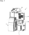
- Fig. 7 is a schematic view illustrating an example of the internal structure of the outdoor unit in Fig. 1 when viewed in the direction from the rear.
- the electrical box 20 may be installed at such a location that the electrical box 20 extends along the rear panel 2C facing the front panel 2B that is a panel as the work surface, or may be installed on the back side (rear side) of a compressor box in which the compressor 6 is accommodated or on the back side (rear side) of the control box 10 when viewed from the front side.
- the devices that do not need regular maintenance are accommodated in the electrical box 20. Accordingly, there are no limitations on the installation location of the electrical box 20, so that the electrical box 20 can be installed at a location where it is difficult for a worker to access it. For this reason, the electrical box 20 can be installed at any location without taking the space in the outdoor unit 1 into consideration.
- the heat medium pipe 8 is accommodated. Since a heat medium with heat circulates through the heat medium pipe 8, the temperature in the vicinity of the heat medium pipe 8 can possibly be increased compared to the temperature at other locations. In the present Embodiment 1, maintenance-free devices that produce a relatively small amount of heat are accommodated in the electrical box 20. In view of that, the electrical box 20 can still be installed even in the vicinity of the heat medium pipe 8 that can possibly heat the inside of the electrical box 20 as described above.
- control box 10 As having been explained in the section "Background Art,” it is considered normal to accommodate a thermal relay in the control box 10 when the thermal relay is added compared to the known technique.
- the control box 10 needs to increase its size to accommodate the thermal relay therein.
- the control box 10 is maintained at its known installation location that satisfies the limitations on its installation, it is difficult to increase the size of the control box 10 from the viewpoint of insufficient space.
- the plurality of thermal relays 21 are accommodated in the electrical box 20 that is formed separately from the control box 10, and the electrical box 20 is installed at a different location from the control box 10. This allows additional thermal relays to be installed in the outdoor unit 1, while the control box 10 is maintained at its installation location.
- the electric wires 22 for the devices accommodated in the electrical box 20 are connected from the lower side of the electrical box 20. This can prevent rain water or other liquid from entering the electrical box 20 via the electric wires 22.
- the electrical box 20 includes the first wire connection port 23a that is a connection port for the first electric wire 22a, and the second wire connection port 23b that is a connection port for the second electric wire 22b.
- the connection ports for the electric wires 22 are provided in such a manner as to separate the connection port for a power wire from the connection port for a wire other than the power wire. This can reduce the likelihood of improper wiring at the time of manufacturing the outdoor unit 1, and can help a worker to easily distinguish between the wires during on-site work.
- the electrical box 20 is installed between the compressor 6 and the fan 4A, each of which has a motor mounted therein. This allows the compressor 6 and the fan 4A to be connected to the electrical box 20 with a shortest distance between them, so that the length of the wire can be minimized and work efficiency for a worker can be improved.
- the electrical box 20 is installed at a height equal to or greater than the set height from the installation surface. This can prevent the occurrence of fire caused by stagnant refrigerant when the refrigerant leaks.
- the electrical box In the outdoor unit 1, the electrical box is installed in the vicinity of the heat medium pipe 8.
- the devices that do not need heat dissipation means or regular maintenance are accommodated in the electrical box 20. Therefore, the electrical box 20 can still be installed even in the vicinity of the heat medium pipe 8 that can possibly heat the inside of the electrical box 20.
- 1 outdoor unit, 2: housing, 2A: top panel, 2B: front panel, 2C: rear panel, 2D: side panel, 2E: bottom panel, 3: suction port, 4: discharge port, 4A: fan, 4B: fan guard, 5: heat-source-side heat exchanger, 6: compressor, 7: water heat exchanger, 8: heat medium pipe, 10: control box, 20: electrical box, 21, 21a, 21b: thermal relay, 22: electric wire, 22a: first electric wire, 22b: second electric wire, 23a: first wire connection port, 23b: second wire connection port
Landscapes
- Engineering & Computer Science (AREA)
- Chemical & Material Sciences (AREA)
- Combustion & Propulsion (AREA)
- Mechanical Engineering (AREA)
- General Engineering & Computer Science (AREA)
- Other Air-Conditioning Systems (AREA)
Abstract
Description
- The present disclosure relates to an outdoor unit of an air-conditioning apparatus in which, for example, the outdoor unit is used as a heat source unit.
- In recent years, from the viewpoint of safety, more stringent electrical regulations require outdoor units of air-conditioning apparatuses to be additionally equipped with a thermal relay. Normally, an outdoor unit is provided with a control box. In the control box, various types of devices that serve as a controller configured to control the air-conditioning apparatus are accommodated (for example, Patent Literature 1). In the control box, many electrical components are accommodated. Examples of the electrical components include a control substrate, an inverter, a capacitor, and a terminal.
- Since this control box is operated by a worker during trial run of the air-conditioning apparatus, in general, the control box needs to be installed at a location that is easily accessible for the worker. In addition, in the control box, many heat-producing devices are accommodated, such as an inverter and a capacitor. For this reason, the control box needs to be installed at a location where the internal heat-producing devices can be sufficiently cooled by air introduced from the outside. Furthermore, in view of work efficiency for a worker and the necessity to avoid the influence of rain that rebounds from the bottom side of the outdoor unit, the control box needs to be positioned at a given height or more from the installation surface of the outdoor unit.
- Patent Literature 1:
Japanese Unexamined Patent Application Publication No. 2011-196560 - In a case where an outdoor unit is additionally equipped with a thermal relay, it is conceivable in general that the thermal relay is also accommodated in the control box along with various types of electrical components. However, there are many electrical components accommodated in the control box. Accordingly, it is difficult to additionally accommodate the thermal relay in the control box.
- It is also conceivable to increase the size of the control box to additionally accommodate the thermal relay therein. However, it is difficult to ensure a space sufficient to install the control box with an increased size at such a regular installation location as to satisfy the limitations described above.
- The present disclosure has been made in view of the above problems associated with the known technique, and it is an object of the present disclosure to provide an outdoor unit of an air-conditioning apparatus in which a thermal relay can be accommodated properly in the outdoor unit without affecting the installation location of a control box.
- An outdoor unit of an air-conditioning apparatus of an embodiment of the present disclosure includes a control box and an electrical box accommodated therein, in the control box, devices serving as a controller configured to control refrigeration cycle-related devices are accommodated, and in the electrical box, devices including a thermal relay are accommodated, the devices producing a smaller amount of heat compared to the devices accommodated in the control box, the electrical box being formed separately from the control box.
- As described above, according to the embodiment of the present disclosure, the devices producing a smaller amount of heat are accommodated in the electrical box that is formed separately from the control box. With this configuration, while the control box is maintained at its installation location, additional thermal relays can be properly installed in the outdoor unit.
-
- [
Fig. 1] Fig. 1 is a schematic view illustrating an example of the exterior appearance of an outdoor unit of an air-conditioning apparatus according toEmbodiment 1. - [
Fig. 2] Fig. 2 is a schematic cross-sectional view of the outdoor unit inFig. 1 when viewed in the direction from the front. - [
Fig. 3] Fig. 3 is a schematic cross-sectional view of the outdoor unit inFig. 1 when viewed in the direction from the top. - [
Fig. 4] Fig. 4 is a schematic view illustrating an example of the internal structure of the outdoor unit according toEmbodiment 1. - [
Fig. 5] Fig. 5 is a schematic view illustrating an example of the internal configuration of an electrical box inFig. 4 . - [
Fig. 6] Fig. 6 is a schematic view illustrating an example of the connection state of wires to the electrical box inFig. 5 . - [
Fig. 7] Fig. 7 is a schematic view illustrating an example of the internal structure of the outdoor unit inFig. 1 when viewed from the rear. - Hereinafter, an embodiment of the present disclosure will be described with reference to the drawings. The present disclosure is not limited to the embodiment described below, and can be variously modified without departing from the scope of the present disclosure. In addition, the present disclosure includes all combinations of configurations that can be combined among the configurations shown in the embodiment described below. The shape, size, location, and other factors of the constituent components described in each of the drawings may be appropriately changed within the scope of the present disclosure.
- In the descriptions below, terms that represent directions (for example, "up," "down," "right," "left," "front," and "rear") are appropriately used for the sake of easily understanding the present disclosure. However, these terms are used merely for description purposes, and the present disclosure is not limited by these terms. In the embodiment described below, the terms such as "up," "down," "right," "left," "front," and "rear" are used in a state where the installation plate is viewed from the front. Note that the relative relationship of sizes of the constituent components, the shapes of the constituent components, and the like in the drawings may differ from those of actual ones.
- An outdoor unit of an air-conditioning apparatus according to the
present Embodiment 1 is described below. The outdoor unit according to thepresent Embodiment 1 is connected to an indoor unit by a heat medium pipe to allow a heat medium such as water or brine to circulate through the heat medium pipe. This outdoor unit is used as, for example, a heat source unit of a heat pump device. -
Fig. 1 is a schematic view illustrating an example of the exterior appearance of the outdoor unit of an air-conditioning apparatus according to thepresent Embodiment 1.Fig. 2 is a schematic cross-sectional view of the outdoor unit inFig. 1 when viewed in the direction from the front.Fig. 3 is a schematic cross-sectional view of the outdoor unit inFig. 1 when viewed in the direction from the top. Note thatFig. 1 omits illustrations of a lower portion of afront panel 2B for the sake of easily understanding the internal structure of theoutdoor unit 1.Figs. 1 and 2 schematically illustrate various types of devices provided inside the outdoor unit. - As illustrated in
Figs. 1 to 3 , theoutdoor unit 1 is formed into, for example, a cuboid shape, and the outer shell of theoutdoor unit 1 is made up of ahousing 2. Thehousing 2 is made up of atop panel 2A, afront panel 2B, a rear panel 2C, twoside panels 2D, and abottom panel 2E. Thebottom panel 2E also serves as a drain pan through which drain water, and rain water or other liquid having entered the inside of theoutdoor unit 1 is discharged to the outside. Note that the drain pan is not limited to this example, and may be provided separately from thebottom panel 2E as another example. -
Suction ports 3 are provided on thefront panel 2B, the rear panel 2C, and the twoside panels 2D to introduce the outside air through thesuction ports 3. At least one of the surfaces defined by thefront panel 2B, the rear panel 2C, and the twoside panels 2D is used as a work surface when a worker performs maintenance work. In this example, the surface defined by thefront panel 2B is used as the work surface. - The
front panel 2B, the rear panel 2C, and the twoside panels 2D are provided along the peripheral edge portion of thebottom panel 2E, extending upward from thebottom panel 2E. Thetop panel 2A is provided on top of these panels. A discharge port 4 is provided on thetop panel 2A to discharge air in theoutdoor unit 1 to the outside through the discharge port 4. The discharge port 4 is made up of afan 4A that serves as a discharge mechanism, and afan guard 4B provided to cover thefan 4A and its surroundings. A heat-source-side heat exchanger 5 is provided at the peripheral edge portion on three sides of thebottom panel 2E, other than one side near thefront panel 2B, such that the heat-source-side heat exchanger 5 extends along the rear panel 2C and the twoside panels 2D. - Next, the internal structure of the
outdoor unit 1 is described.Fig. 4 is a schematic view illustrating an example of the internal structure of the outdoor unit according to thepresent Embodiment 1. Note that for the sake of easily understanding the internal structure of theoutdoor unit 1,Fig. 4 omits illustrations of thehousing 2 and devices which do not need to be described. - In the
housing 2 of theoutdoor unit 1, various types of refrigeration cycle-related devices are accommodated. Examples of the refrigeration cycle-related devices include acompressor 6 that compresses refrigerant, a pressure reducing device (not illustrated) that reduces the pressure of refrigerant, and awater heat exchanger 7 that exchanges heat between the refrigerant and the heat medium. These devices, including thecompressor 6, the heat-source-side heat exchanger 5, the pressure reducing device, and thewater heat exchanger 7, are connected by a refrigerant pipe to allow the refrigerant to circulate through these devices. This refrigerant pipe is also accommodated in thehousing 2. Aheat medium pipe 8 through which the heat medium circulates is connected to thewater heat exchanger 7. Theheat medium pipe 8 is also accommodated in thehousing 2. Theoutdoor unit 1 has acontrol box 10 and anelectrical box 20 accommodated therein. - In the
control box 10, electrical components are accommodated. The electrical components serve as a controller configured to control the refrigeration cycle-related devices such as thecompressor 6 and the pressure reducing device provided in the air-conditioning apparatus including theoutdoor unit 1. Examples of the electrical components accommodated in thecontrol box 10 include a control substrate, an inverter, a capacitor, and a terminal. - Since the
control box 10 is operated by a worker during trial run of the air-conditioning apparatus, thecontrol box 10 needs to be installed at a location that is easily accessible for the worker. In thecontrol box 10, many heat-producing devices such as an inverter and a capacitor are accommodated. The heat-producing devices produce a relatively large amount of heat and thus need heat dissipation means. Accordingly, it is necessary to position the internal heat-producing devices at a location where they can be sufficiently cooled. Furthermore, in consideration of work efficiency for a worker, the influence of rain that rebounds from thebottom panel 2E, and other factors, thecontrol box 10 needs to be installed at a given height or more from thebottom panel 2E. Therefore, in theoutdoor unit 1 according to thepresent Embodiment 1, thecontrol box 10 is installed, extending along thefront panel 2B that is a panel as the work surface, while being installed at a given height or more from thebottom panel 2E. -
Fig. 5 is a schematic view illustrating an example of the internal configuration of the electrical box inFig. 4 . As illustrated inFig. 5 ,thermal relays 21 are accommodated in theelectrical box 20. In this example, twothermal relays electrical box 20. - The thermal relays 21 are provided to protect motors from burnout caused by an overcurrent flow due to an overload on the motors or other reasons. In the
outdoor unit 1 according to thepresent Embodiment 1, motors are mounted in thecompressor 6 and thefan 4A. The thermal relays 21 are provided to protect these motors from burnout. Note that theoutdoor unit 1 of an air-conditioning apparatus uses a plurality of rotational elements with different capacities, such as thecompressor 6 and thefan 4A. In view of that, preferably a plurality ofthermal relays 21 are provided corresponding to the individual rotational elements. - In the
electrical box 20, devices that produce a relatively small amount of heat, including the plurality ofthermal relays 21, as well as devices that do not need regular maintenance are accommodated. The "devices that produce a relatively small amount of heat" refer to a device that does not need heat dissipation means. Examples of the device include a device that produces a smaller amount of heat and thus does not need to be cooled by a heatsink, compared to the electrical components accommodated in thecontrol box 10 such as an inverter and a variable voltage regulator. -
Fig. 6 is a schematic view illustrating an example of the connection state of wires to the electrical box inFig. 5 . As illustrated inFig. 6 , a plurality ofelectric wires 22 are connected to the devices accommodated in theelectrical box 20. Theseelectric wires 22 are connected from the lower side of theelectrical box 20. This can prevent rain water or other liquid from entering theelectrical box 20 via the wires. - The
electric wires 22 include a firstelectric wire 22a that is a power wire, and a secondelectric wire 22b other than the power wire. On the lower side of theelectrical box 20, a firstwire connection port 23a and a secondwire connection port 23b are formed. The firstwire connection port 23a is a connection port for the firstelectric wire 22a. The secondwire connection port 23b is a connection port for the secondelectric wire 22b. - In the
present Embodiment 1, the connection ports for theelectric wires 22 are provided in such a manner as to separate the connection port for a power wire from the connection port for a wire other than the power wire. This can reduce the likelihood of improper wiring at the time of manufacturing theoutdoor unit 1. This also helps a worker to easily distinguish between the wires during on-site work. - Preferably, the
electrical box 20 is installed between motor-mounted devices, for example, between thecompressor 6 and thefan 4A. This allows thecompressor 6 and thefan 4A to be connected to theelectrical box 20 with a shortest distance between them, so that the length of the wire can be minimized and work efficiency for a worker can be improved. - When refrigerant leaks in the
outdoor unit 1, the refrigerant is stagnant in the lower portion of theoutdoor unit 1. The reason for this is that the refrigerant is heavier than air. Accordingly, when flammable refrigerant is used as the refrigerant, theelectrical box 20 is installed at a height equal to or greater than the set height of approximately 50 mm from the installation surface of theoutdoor unit 1 to prevent the occurrence of fire caused by the stagnant refrigerant. - As described above, in the
electrical box 20, devices that produce a relatively small amount of heat and thus do not need heat dissipation means are accommodated. As the devices do not need heat dissipation means, these devices do not need regular maintenance. Consequently, theelectrical box 20 does not need to be installed at a location that is accessible for a worker. For example, theelectrical box 20 may be installed at a location where it is difficult for a worker to see the work spot during work and where it is difficult to access theelectrical box 20. -
Fig. 7 is a schematic view illustrating an example of the internal structure of the outdoor unit inFig. 1 when viewed in the direction from the rear. As illustrated inFig. 7 , for example, theelectrical box 20 may be installed at such a location that theelectrical box 20 extends along the rear panel 2C facing thefront panel 2B that is a panel as the work surface, or may be installed on the back side (rear side) of a compressor box in which thecompressor 6 is accommodated or on the back side (rear side) of thecontrol box 10 when viewed from the front side. - The devices that do not need regular maintenance are accommodated in the
electrical box 20. Accordingly, there are no limitations on the installation location of theelectrical box 20, so that theelectrical box 20 can be installed at a location where it is difficult for a worker to access it. For this reason, theelectrical box 20 can be installed at any location without taking the space in theoutdoor unit 1 into consideration. - In the
outdoor unit 1, for example, theheat medium pipe 8 is accommodated. Since a heat medium with heat circulates through theheat medium pipe 8, the temperature in the vicinity of theheat medium pipe 8 can possibly be increased compared to the temperature at other locations. In thepresent Embodiment 1, maintenance-free devices that produce a relatively small amount of heat are accommodated in theelectrical box 20. In view of that, theelectrical box 20 can still be installed even in the vicinity of theheat medium pipe 8 that can possibly heat the inside of theelectrical box 20 as described above. - As having been explained in the section "Background Art," it is considered normal to accommodate a thermal relay in the
control box 10 when the thermal relay is added compared to the known technique. Thecontrol box 10 needs to increase its size to accommodate the thermal relay therein. However, assuming that thecontrol box 10 is maintained at its known installation location that satisfies the limitations on its installation, it is difficult to increase the size of thecontrol box 10 from the viewpoint of insufficient space. - In contrast to this, in the
present Embodiment 1, the plurality ofthermal relays 21 are accommodated in theelectrical box 20 that is formed separately from thecontrol box 10, and theelectrical box 20 is installed at a different location from thecontrol box 10. This allows additional thermal relays to be installed in theoutdoor unit 1, while thecontrol box 10 is maintained at its installation location. - As described above, in the
outdoor unit 1 of an air-conditioning apparatus according to thepresent Embodiment 1, devices that produce a relatively small amount of heat are accommodated in theelectrical box 20 that is formed separately from thecontrol box 10. This allows additionalthermal relays 21 to be installed in theoutdoor unit 1, while thecontrol box 10 is maintained at its installation location. - In the
outdoor unit 1, theelectric wires 22 for the devices accommodated in theelectrical box 20 are connected from the lower side of theelectrical box 20. This can prevent rain water or other liquid from entering theelectrical box 20 via theelectric wires 22. - In the
outdoor unit 1, theelectrical box 20 includes the firstwire connection port 23a that is a connection port for the firstelectric wire 22a, and the secondwire connection port 23b that is a connection port for the secondelectric wire 22b. As described above, the connection ports for theelectric wires 22 are provided in such a manner as to separate the connection port for a power wire from the connection port for a wire other than the power wire. This can reduce the likelihood of improper wiring at the time of manufacturing theoutdoor unit 1, and can help a worker to easily distinguish between the wires during on-site work. - In the
outdoor unit 1, theelectrical box 20 is installed between thecompressor 6 and thefan 4A, each of which has a motor mounted therein. This allows thecompressor 6 and thefan 4A to be connected to theelectrical box 20 with a shortest distance between them, so that the length of the wire can be minimized and work efficiency for a worker can be improved. - In the
outdoor unit 1, theelectrical box 20 is installed at a height equal to or greater than the set height from the installation surface. This can prevent the occurrence of fire caused by stagnant refrigerant when the refrigerant leaks. - In the
outdoor unit 1, the electrical box is installed in the vicinity of theheat medium pipe 8. The devices that do not need heat dissipation means or regular maintenance are accommodated in theelectrical box 20. Therefore, theelectrical box 20 can still be installed even in the vicinity of theheat medium pipe 8 that can possibly heat the inside of theelectrical box 20. - 1: outdoor unit, 2: housing, 2A: top panel, 2B: front panel, 2C: rear panel, 2D: side panel, 2E: bottom panel, 3: suction port, 4: discharge port, 4A: fan, 4B: fan guard, 5: heat-source-side heat exchanger, 6: compressor, 7: water heat exchanger, 8: heat medium pipe, 10: control box, 20: electrical box, 21, 21a, 21b: thermal relay, 22: electric wire, 22a: first electric wire, 22b: second electric wire, 23a: first wire connection port, 23b: second wire connection port
Claims (6)
- An outdoor unit of an air-conditioning apparatus, whereinthe outdoor unit has a control box and an electrical box accommodated therein,in the control box, devices serving as a controller configured to control refrigeration cycle-related devices are accommodated, andin the electrical box, devices including a thermal relay are accommodated, the devices producing a smaller amount of heat compared to the devices accommodated in the control box, the electrical box being formed separately from the control box.
- The outdoor unit of an air-conditioning apparatus of claim 1, wherein
electric wires for the devices accommodated in the electrical box are connected from a lower side of the electrical box. - The outdoor unit of an air-conditioning apparatus of claim 2, whereinthe electric wires includea first electric wire that is a power wire, anda second electric wire that is other than the power wire, andthe electrical box includesa first wire connection port that is a connection port for the first electric wire, anda second wire connection port that is a connection port for the second electric wire.
- The outdoor unit of an air-conditioning apparatus of any one of claims 1 to 3, wherein the electrical box is installed between a compressor and a fan, the compressor and the fan being included in the refrigeration cycle-related devices.
- The outdoor unit of an air-conditioning apparatus of any one of claims 1 to 4, wherein the electrical box is installed at a height equal to or greater than a set height from an installation surface.
- The outdoor unit of an air-conditioning apparatus of any one of claims 1 to 5, whereina heat medium pipe through which a heat medium circulates is accommodated in the outdoor unit, andthe electrical box is installed in a vicinity of the heat medium pipe.
Applications Claiming Priority (1)
| Application Number | Priority Date | Filing Date | Title |
|---|---|---|---|
| PCT/JP2020/046844 WO2022130518A1 (en) | 2020-12-16 | 2020-12-16 | Outdoor unit of air conditioning device |
Publications (3)
| Publication Number | Publication Date |
|---|---|
| EP4265968A1 true EP4265968A1 (en) | 2023-10-25 |
| EP4265968A4 EP4265968A4 (en) | 2024-01-17 |
| EP4265968B1 EP4265968B1 (en) | 2025-08-13 |
Family
ID=82059233
Family Applications (1)
| Application Number | Title | Priority Date | Filing Date |
|---|---|---|---|
| EP20965906.9A Active EP4265968B1 (en) | 2020-12-16 | 2020-12-16 | Outdoor unit of air conditioning device |
Country Status (3)
| Country | Link |
|---|---|
| US (1) | US12467642B2 (en) |
| EP (1) | EP4265968B1 (en) |
| WO (1) | WO2022130518A1 (en) |
Family Cites Families (12)
| Publication number | Priority date | Publication date | Assignee | Title |
|---|---|---|---|---|
| JP2925980B2 (en) | 1995-05-23 | 1999-07-28 | 三洋電機株式会社 | Heat exchange unit |
| JP2003274683A (en) * | 2002-03-14 | 2003-09-26 | Sanyo Electric Co Ltd | Protecting apparatus of motor |
| JP5375349B2 (en) * | 2009-06-10 | 2013-12-25 | ダイキン工業株式会社 | Transportation refrigeration equipment |
| JP5549296B2 (en) | 2010-03-17 | 2014-07-16 | パナソニック株式会社 | Heat pump water heater |
| JP5304865B2 (en) * | 2011-09-29 | 2013-10-02 | ダイキン工業株式会社 | Air conditioner outdoor unit |
| WO2013145013A1 (en) * | 2012-03-29 | 2013-10-03 | 三菱電機株式会社 | Branch controller and air-conditioning device provided therewith |
| CN104251522B (en) * | 2013-06-28 | 2019-04-26 | 珠海格力电器股份有限公司 | Air conditioner electrical box assembly and air conditioner outdoor unit thereof |
| JP2016201473A (en) | 2015-04-10 | 2016-12-01 | 東芝キヤリア株式会社 | Refrigeration cycle device and method of controlling the same |
| WO2017077647A1 (en) * | 2015-11-06 | 2017-05-11 | 三菱電機株式会社 | Outdoor unit and air-conditioner using same |
| JP6599007B2 (en) * | 2016-07-22 | 2019-10-30 | 三菱電機株式会社 | Air conditioner |
| JP6593402B2 (en) * | 2017-08-09 | 2019-10-23 | ダイキン工業株式会社 | Refrigeration unit outdoor unit |
| JP6749293B2 (en) * | 2017-08-09 | 2020-09-02 | ダイキン工業株式会社 | Outdoor unit of refrigeration equipment |
-
2020
- 2020-12-16 WO PCT/JP2020/046844 patent/WO2022130518A1/en not_active Ceased
- 2020-12-16 EP EP20965906.9A patent/EP4265968B1/en active Active
- 2020-12-16 US US18/245,392 patent/US12467642B2/en active Active
Also Published As
| Publication number | Publication date |
|---|---|
| US20230349565A1 (en) | 2023-11-02 |
| US12467642B2 (en) | 2025-11-11 |
| WO2022130518A1 (en) | 2022-06-23 |
| EP4265968A4 (en) | 2024-01-17 |
| EP4265968B1 (en) | 2025-08-13 |
Similar Documents
| Publication | Publication Date | Title |
|---|---|---|
| EP1956309A1 (en) | Electrical parts assembly, outdoor unit of air conditioner having the same, and air conditioner | |
| US11209175B2 (en) | Outdoor unit for refrigeration apparatus | |
| US7363768B2 (en) | Outdoor unit of refrigerator, and electrical equipment box of outdoor unit | |
| JP2009089511A (en) | Electric compressor for onboard air conditioner | |
| EP3882529B1 (en) | Outdoor unit for air conditioner | |
| US7876574B2 (en) | Electric equipment assembly and outdoor unit of air conditioner provided with the same | |
| EP4102143B1 (en) | Heat pump heat source device | |
| EP3147579B1 (en) | Outdoor equipment for refrigeration cycle device | |
| EP3051216B1 (en) | Outdoor unit of air conditioner, and air conditioner | |
| EP3392573B1 (en) | Outdoor machine for freezing cycle apparatus | |
| JP2013135196A (en) | Cooling structure of electrical box | |
| CN1764808A (en) | Recirculation cooling system | |
| JP2007278559A (en) | Outdoor unit of air conditioner | |
| US12467642B2 (en) | Outdoor unit of air-conditioning apparatus | |
| CN101266063B (en) | Outdoor machine of air conditioner | |
| EP3514457B1 (en) | Heat source unit | |
| JP5423322B2 (en) | Air conditioner outdoor unit | |
| EP4027065B1 (en) | Outdoor unit of refrigeration device | |
| EP4321811A1 (en) | Outdoor unit | |
| EP4560207A1 (en) | Outdoor unit for a heat pump | |
| EP4345387A1 (en) | Heat pump apparatus | |
| JP3974609B2 (en) | Cubicle | |
| EP4306868A1 (en) | Outdoor unit | |
| JP2023134102A (en) | Outdoor unit of air conditioner | |
| CN116097040A (en) | Outdoor unit of air conditioner |
Legal Events
| Date | Code | Title | Description |
|---|---|---|---|
| STAA | Information on the status of an ep patent application or granted ep patent |
Free format text: STATUS: THE INTERNATIONAL PUBLICATION HAS BEEN MADE |
|
| PUAI | Public reference made under article 153(3) epc to a published international application that has entered the european phase |
Free format text: ORIGINAL CODE: 0009012 |
|
| STAA | Information on the status of an ep patent application or granted ep patent |
Free format text: STATUS: REQUEST FOR EXAMINATION WAS MADE |
|
| 17P | Request for examination filed |
Effective date: 20230426 |
|
| AK | Designated contracting states |
Kind code of ref document: A1 Designated state(s): AL AT BE BG CH CY CZ DE DK EE ES FI FR GB GR HR HU IE IS IT LI LT LU LV MC MK MT NL NO PL PT RO RS SE SI SK SM TR |
|
| A4 | Supplementary search report drawn up and despatched |
Effective date: 20231219 |
|
| RIC1 | Information provided on ipc code assigned before grant |
Ipc: F24F 11/88 20180101ALI20231213BHEP Ipc: F24F 1/22 20110101AFI20231213BHEP |
|
| DAV | Request for validation of the european patent (deleted) | ||
| DAX | Request for extension of the european patent (deleted) | ||
| GRAP | Despatch of communication of intention to grant a patent |
Free format text: ORIGINAL CODE: EPIDOSNIGR1 |
|
| STAA | Information on the status of an ep patent application or granted ep patent |
Free format text: STATUS: GRANT OF PATENT IS INTENDED |
|
| RIC1 | Information provided on ipc code assigned before grant |
Ipc: F24F 11/88 20180101ALI20250305BHEP Ipc: F24F 1/22 20110101AFI20250305BHEP |
|
| INTG | Intention to grant announced |
Effective date: 20250313 |
|
| GRAS | Grant fee paid |
Free format text: ORIGINAL CODE: EPIDOSNIGR3 |
|
| GRAA | (expected) grant |
Free format text: ORIGINAL CODE: 0009210 |
|
| STAA | Information on the status of an ep patent application or granted ep patent |
Free format text: STATUS: THE PATENT HAS BEEN GRANTED |
|
| AK | Designated contracting states |
Kind code of ref document: B1 Designated state(s): AL AT BE BG CH CY CZ DE DK EE ES FI FR GB GR HR HU IE IS IT LI LT LU LV MC MK MT NL NO PL PT RO RS SE SI SK SM TR |
|
| REG | Reference to a national code |
Ref country code: GB Ref legal event code: FG4D |
|
| REG | Reference to a national code |
Ref country code: CH Ref legal event code: EP |
|
| REG | Reference to a national code |
Ref country code: DE Ref legal event code: R096 Ref document number: 602020056794 Country of ref document: DE |
|
| REG | Reference to a national code |
Ref country code: IE Ref legal event code: FG4D |
|
| REG | Reference to a national code |
Ref country code: NL Ref legal event code: MP Effective date: 20250813 |
|
| PG25 | Lapsed in a contracting state [announced via postgrant information from national office to epo] |
Ref country code: IS Free format text: LAPSE BECAUSE OF FAILURE TO SUBMIT A TRANSLATION OF THE DESCRIPTION OR TO PAY THE FEE WITHIN THE PRESCRIBED TIME-LIMIT Effective date: 20251213 |
|
| PGFP | Annual fee paid to national office [announced via postgrant information from national office to epo] |
Ref country code: DE Payment date: 20251028 Year of fee payment: 6 |
|
| PGFP | Annual fee paid to national office [announced via postgrant information from national office to epo] |
Ref country code: GB Payment date: 20251030 Year of fee payment: 6 |
|
| PG25 | Lapsed in a contracting state [announced via postgrant information from national office to epo] |
Ref country code: NO Free format text: LAPSE BECAUSE OF FAILURE TO SUBMIT A TRANSLATION OF THE DESCRIPTION OR TO PAY THE FEE WITHIN THE PRESCRIBED TIME-LIMIT Effective date: 20251113 |
|
| REG | Reference to a national code |
Ref country code: LT Ref legal event code: MG9D |
|
| PG25 | Lapsed in a contracting state [announced via postgrant information from national office to epo] |
Ref country code: PT Free format text: LAPSE BECAUSE OF FAILURE TO SUBMIT A TRANSLATION OF THE DESCRIPTION OR TO PAY THE FEE WITHIN THE PRESCRIBED TIME-LIMIT Effective date: 20251215 |
|
| PG25 | Lapsed in a contracting state [announced via postgrant information from national office to epo] |
Ref country code: FI Free format text: LAPSE BECAUSE OF FAILURE TO SUBMIT A TRANSLATION OF THE DESCRIPTION OR TO PAY THE FEE WITHIN THE PRESCRIBED TIME-LIMIT Effective date: 20250813 |
|
| PG25 | Lapsed in a contracting state [announced via postgrant information from national office to epo] |
Ref country code: HR Free format text: LAPSE BECAUSE OF FAILURE TO SUBMIT A TRANSLATION OF THE DESCRIPTION OR TO PAY THE FEE WITHIN THE PRESCRIBED TIME-LIMIT Effective date: 20250813 Ref country code: NL Free format text: LAPSE BECAUSE OF FAILURE TO SUBMIT A TRANSLATION OF THE DESCRIPTION OR TO PAY THE FEE WITHIN THE PRESCRIBED TIME-LIMIT Effective date: 20250813 |
|
| PG25 | Lapsed in a contracting state [announced via postgrant information from national office to epo] |
Ref country code: GR Free format text: LAPSE BECAUSE OF FAILURE TO SUBMIT A TRANSLATION OF THE DESCRIPTION OR TO PAY THE FEE WITHIN THE PRESCRIBED TIME-LIMIT Effective date: 20251114 |
|
| PG25 | Lapsed in a contracting state [announced via postgrant information from national office to epo] |
Ref country code: SE Free format text: LAPSE BECAUSE OF FAILURE TO SUBMIT A TRANSLATION OF THE DESCRIPTION OR TO PAY THE FEE WITHIN THE PRESCRIBED TIME-LIMIT Effective date: 20250813 |
|
| PG25 | Lapsed in a contracting state [announced via postgrant information from national office to epo] |
Ref country code: LV Free format text: LAPSE BECAUSE OF FAILURE TO SUBMIT A TRANSLATION OF THE DESCRIPTION OR TO PAY THE FEE WITHIN THE PRESCRIBED TIME-LIMIT Effective date: 20250813 |
|
| PG25 | Lapsed in a contracting state [announced via postgrant information from national office to epo] |
Ref country code: PL Free format text: LAPSE BECAUSE OF FAILURE TO SUBMIT A TRANSLATION OF THE DESCRIPTION OR TO PAY THE FEE WITHIN THE PRESCRIBED TIME-LIMIT Effective date: 20250813 Ref country code: BG Free format text: LAPSE BECAUSE OF FAILURE TO SUBMIT A TRANSLATION OF THE DESCRIPTION OR TO PAY THE FEE WITHIN THE PRESCRIBED TIME-LIMIT Effective date: 20250813 |
|
| PG25 | Lapsed in a contracting state [announced via postgrant information from national office to epo] |
Ref country code: RS Free format text: LAPSE BECAUSE OF FAILURE TO SUBMIT A TRANSLATION OF THE DESCRIPTION OR TO PAY THE FEE WITHIN THE PRESCRIBED TIME-LIMIT Effective date: 20251113 |
|
| PG25 | Lapsed in a contracting state [announced via postgrant information from national office to epo] |
Ref country code: ES Free format text: LAPSE BECAUSE OF FAILURE TO SUBMIT A TRANSLATION OF THE DESCRIPTION OR TO PAY THE FEE WITHIN THE PRESCRIBED TIME-LIMIT Effective date: 20250813 |
|
| REG | Reference to a national code |
Ref country code: AT Ref legal event code: MK05 Ref document number: 1825012 Country of ref document: AT Kind code of ref document: T Effective date: 20250813 |
|
| PG25 | Lapsed in a contracting state [announced via postgrant information from national office to epo] |
Ref country code: RO Free format text: LAPSE BECAUSE OF FAILURE TO SUBMIT A TRANSLATION OF THE DESCRIPTION OR TO PAY THE FEE WITHIN THE PRESCRIBED TIME-LIMIT Effective date: 20250813 |
|
| PG25 | Lapsed in a contracting state [announced via postgrant information from national office to epo] |
Ref country code: SM Free format text: LAPSE BECAUSE OF FAILURE TO SUBMIT A TRANSLATION OF THE DESCRIPTION OR TO PAY THE FEE WITHIN THE PRESCRIBED TIME-LIMIT Effective date: 20250813 |
|
| PG25 | Lapsed in a contracting state [announced via postgrant information from national office to epo] |
Ref country code: DK Free format text: LAPSE BECAUSE OF FAILURE TO SUBMIT A TRANSLATION OF THE DESCRIPTION OR TO PAY THE FEE WITHIN THE PRESCRIBED TIME-LIMIT Effective date: 20250813 |
|
| PG25 | Lapsed in a contracting state [announced via postgrant information from national office to epo] |
Ref country code: AT Free format text: LAPSE BECAUSE OF FAILURE TO SUBMIT A TRANSLATION OF THE DESCRIPTION OR TO PAY THE FEE WITHIN THE PRESCRIBED TIME-LIMIT Effective date: 20250813 |
|
| PG25 | Lapsed in a contracting state [announced via postgrant information from national office to epo] |
Ref country code: IT Free format text: LAPSE BECAUSE OF FAILURE TO SUBMIT A TRANSLATION OF THE DESCRIPTION OR TO PAY THE FEE WITHIN THE PRESCRIBED TIME-LIMIT Effective date: 20250813 |
|
| PG25 | Lapsed in a contracting state [announced via postgrant information from national office to epo] |
Ref country code: CZ Free format text: LAPSE BECAUSE OF FAILURE TO SUBMIT A TRANSLATION OF THE DESCRIPTION OR TO PAY THE FEE WITHIN THE PRESCRIBED TIME-LIMIT Effective date: 20250813 |
|
| PG25 | Lapsed in a contracting state [announced via postgrant information from national office to epo] |
Ref country code: EE Free format text: LAPSE BECAUSE OF FAILURE TO SUBMIT A TRANSLATION OF THE DESCRIPTION OR TO PAY THE FEE WITHIN THE PRESCRIBED TIME-LIMIT Effective date: 20250813 Ref country code: SK Free format text: LAPSE BECAUSE OF FAILURE TO SUBMIT A TRANSLATION OF THE DESCRIPTION OR TO PAY THE FEE WITHIN THE PRESCRIBED TIME-LIMIT Effective date: 20250813 |