EP4265942A1 - Hydraulic fluid flow control - Google Patents
Hydraulic fluid flow control Download PDFInfo
- Publication number
- EP4265942A1 EP4265942A1 EP23168815.1A EP23168815A EP4265942A1 EP 4265942 A1 EP4265942 A1 EP 4265942A1 EP 23168815 A EP23168815 A EP 23168815A EP 4265942 A1 EP4265942 A1 EP 4265942A1
- Authority
- EP
- European Patent Office
- Prior art keywords
- gear
- brake
- hydraulic fluid
- reduction
- coupled
- Prior art date
- Legal status (The legal status is an assumption and is not a legal conclusion. Google has not performed a legal analysis and makes no representation as to the accuracy of the status listed.)
- Granted
Links
Images

Classifications
-
- F—MECHANICAL ENGINEERING; LIGHTING; HEATING; WEAPONS; BLASTING
- F16—ENGINEERING ELEMENTS AND UNITS; GENERAL MEASURES FOR PRODUCING AND MAINTAINING EFFECTIVE FUNCTIONING OF MACHINES OR INSTALLATIONS; THERMAL INSULATION IN GENERAL
- F16H—GEARING
- F16H61/00—Control functions within control units of change-speed- or reversing-gearings for conveying rotary motion ; Control of exclusively fluid gearing, friction gearing, gearings with endless flexible members or other particular types of gearing
- F16H61/38—Control of exclusively fluid gearing
- F16H61/40—Control of exclusively fluid gearing hydrostatic
- F16H61/44—Control of exclusively fluid gearing hydrostatic with more than one pump or motor in operation
-
- F—MECHANICAL ENGINEERING; LIGHTING; HEATING; WEAPONS; BLASTING
- F15—FLUID-PRESSURE ACTUATORS; HYDRAULICS OR PNEUMATICS IN GENERAL
- F15B—SYSTEMS ACTING BY MEANS OF FLUIDS IN GENERAL; FLUID-PRESSURE ACTUATORS, e.g. SERVOMOTORS; DETAILS OF FLUID-PRESSURE SYSTEMS, NOT OTHERWISE PROVIDED FOR
- F15B15/00—Fluid-actuated devices for displacing a member from one position to another; Gearing associated therewith
- F15B15/02—Mechanical layout characterised by the means for converting the movement of the fluid-actuated element into movement of the finally-operated member
-
- B—PERFORMING OPERATIONS; TRANSPORTING
- B60—VEHICLES IN GENERAL
- B60T—VEHICLE BRAKE CONTROL SYSTEMS OR PARTS THEREOF; BRAKE CONTROL SYSTEMS OR PARTS THEREOF, IN GENERAL; ARRANGEMENT OF BRAKING ELEMENTS ON VEHICLES IN GENERAL; PORTABLE DEVICES FOR PREVENTING UNWANTED MOVEMENT OF VEHICLES; VEHICLE MODIFICATIONS TO FACILITATE COOLING OF BRAKES
- B60T10/00—Control or regulation for continuous braking making use of fluid or powdered medium, e.g. for use when descending a long slope
- B60T10/04—Control or regulation for continuous braking making use of fluid or powdered medium, e.g. for use when descending a long slope with hydrostatic brake
-
- F—MECHANICAL ENGINEERING; LIGHTING; HEATING; WEAPONS; BLASTING
- F03—MACHINES OR ENGINES FOR LIQUIDS; WIND, SPRING, OR WEIGHT MOTORS; PRODUCING MECHANICAL POWER OR A REACTIVE PROPULSIVE THRUST, NOT OTHERWISE PROVIDED FOR
- F03C—POSITIVE-DISPLACEMENT ENGINES DRIVEN BY LIQUIDS
- F03C2/00—Rotary-piston engines
- F03C2/08—Rotary-piston engines of intermeshing-engagement type, i.e. with engagement of co- operating members similar to that of toothed gearing
-
- F—MECHANICAL ENGINEERING; LIGHTING; HEATING; WEAPONS; BLASTING
- F04—POSITIVE - DISPLACEMENT MACHINES FOR LIQUIDS; PUMPS FOR LIQUIDS OR ELASTIC FLUIDS
- F04C—ROTARY-PISTON, OR OSCILLATING-PISTON, POSITIVE-DISPLACEMENT MACHINES FOR LIQUIDS; ROTARY-PISTON, OR OSCILLATING-PISTON, POSITIVE-DISPLACEMENT PUMPS
- F04C15/00—Component parts, details or accessories of machines, pumps or pumping installations, not provided for in groups F04C2/00 - F04C14/00
- F04C15/0057—Driving elements, brakes, couplings, transmission specially adapted for machines or pumps
- F04C15/0061—Means for transmitting movement from the prime mover to driven parts of the pump, e.g. clutches, couplings, transmissions
-
- F—MECHANICAL ENGINEERING; LIGHTING; HEATING; WEAPONS; BLASTING
- F04—POSITIVE - DISPLACEMENT MACHINES FOR LIQUIDS; PUMPS FOR LIQUIDS OR ELASTIC FLUIDS
- F04C—ROTARY-PISTON, OR OSCILLATING-PISTON, POSITIVE-DISPLACEMENT MACHINES FOR LIQUIDS; ROTARY-PISTON, OR OSCILLATING-PISTON, POSITIVE-DISPLACEMENT PUMPS
- F04C15/00—Component parts, details or accessories of machines, pumps or pumping installations, not provided for in groups F04C2/00 - F04C14/00
- F04C15/0057—Driving elements, brakes, couplings, transmission specially adapted for machines or pumps
- F04C15/0084—Brakes, braking assemblies
-
- F—MECHANICAL ENGINEERING; LIGHTING; HEATING; WEAPONS; BLASTING
- F16—ENGINEERING ELEMENTS AND UNITS; GENERAL MEASURES FOR PRODUCING AND MAINTAINING EFFECTIVE FUNCTIONING OF MACHINES OR INSTALLATIONS; THERMAL INSULATION IN GENERAL
- F16D—COUPLINGS FOR TRANSMITTING ROTATION; CLUTCHES; BRAKES
- F16D57/00—Liquid-resistance brakes; Brakes using the internal friction of fluids or fluid-like media, e.g. powders
- F16D57/002—Liquid-resistance brakes; Brakes using the internal friction of fluids or fluid-like media, e.g. powders comprising a medium with electrically or magnetically controlled internal friction, e.g. electrorheological fluid, magnetic powder
-
- F—MECHANICAL ENGINEERING; LIGHTING; HEATING; WEAPONS; BLASTING
- F16—ENGINEERING ELEMENTS AND UNITS; GENERAL MEASURES FOR PRODUCING AND MAINTAINING EFFECTIVE FUNCTIONING OF MACHINES OR INSTALLATIONS; THERMAL INSULATION IN GENERAL
- F16F—SPRINGS; SHOCK-ABSORBERS; MEANS FOR DAMPING VIBRATION
- F16F9/00—Springs, vibration-dampers, shock-absorbers, or similarly-constructed movement-dampers using a fluid or the equivalent as damping medium
- F16F9/32—Details
- F16F9/53—Means for adjusting damping characteristics by varying fluid viscosity, e.g. electromagnetically
- F16F9/532—Electrorheological [ER] fluid dampers
-
- F—MECHANICAL ENGINEERING; LIGHTING; HEATING; WEAPONS; BLASTING
- F16—ENGINEERING ELEMENTS AND UNITS; GENERAL MEASURES FOR PRODUCING AND MAINTAINING EFFECTIVE FUNCTIONING OF MACHINES OR INSTALLATIONS; THERMAL INSULATION IN GENERAL
- F16F—SPRINGS; SHOCK-ABSORBERS; MEANS FOR DAMPING VIBRATION
- F16F9/00—Springs, vibration-dampers, shock-absorbers, or similarly-constructed movement-dampers using a fluid or the equivalent as damping medium
- F16F9/32—Details
- F16F9/53—Means for adjusting damping characteristics by varying fluid viscosity, e.g. electromagnetically
- F16F9/535—Magnetorheological [MR] fluid dampers
-
- F—MECHANICAL ENGINEERING; LIGHTING; HEATING; WEAPONS; BLASTING
- F16—ENGINEERING ELEMENTS AND UNITS; GENERAL MEASURES FOR PRODUCING AND MAINTAINING EFFECTIVE FUNCTIONING OF MACHINES OR INSTALLATIONS; THERMAL INSULATION IN GENERAL
- F16H—GEARING
- F16H47/00—Combinations of mechanical gearing with fluid clutches or fluid gearing
- F16H47/02—Combinations of mechanical gearing with fluid clutches or fluid gearing the fluid gearing being of the volumetric type
-
- F—MECHANICAL ENGINEERING; LIGHTING; HEATING; WEAPONS; BLASTING
- F16—ENGINEERING ELEMENTS AND UNITS; GENERAL MEASURES FOR PRODUCING AND MAINTAINING EFFECTIVE FUNCTIONING OF MACHINES OR INSTALLATIONS; THERMAL INSULATION IN GENERAL
- F16H—GEARING
- F16H61/00—Control functions within control units of change-speed- or reversing-gearings for conveying rotary motion ; Control of exclusively fluid gearing, friction gearing, gearings with endless flexible members or other particular types of gearing
- F16H61/38—Control of exclusively fluid gearing
- F16H61/40—Control of exclusively fluid gearing hydrostatic
- F16H61/44—Control of exclusively fluid gearing hydrostatic with more than one pump or motor in operation
- F16H61/444—Control of exclusively fluid gearing hydrostatic with more than one pump or motor in operation by changing the number of pump or motor units in operation
-
- F—MECHANICAL ENGINEERING; LIGHTING; HEATING; WEAPONS; BLASTING
- F04—POSITIVE - DISPLACEMENT MACHINES FOR LIQUIDS; PUMPS FOR LIQUIDS OR ELASTIC FLUIDS
- F04C—ROTARY-PISTON, OR OSCILLATING-PISTON, POSITIVE-DISPLACEMENT MACHINES FOR LIQUIDS; ROTARY-PISTON, OR OSCILLATING-PISTON, POSITIVE-DISPLACEMENT PUMPS
- F04C2240/00—Components
- F04C2240/80—Other components
- F04C2240/81—Sensor, e.g. electronic sensor for control or monitoring
-
- F—MECHANICAL ENGINEERING; LIGHTING; HEATING; WEAPONS; BLASTING
- F04—POSITIVE - DISPLACEMENT MACHINES FOR LIQUIDS; PUMPS FOR LIQUIDS OR ELASTIC FLUIDS
- F04C—ROTARY-PISTON, OR OSCILLATING-PISTON, POSITIVE-DISPLACEMENT MACHINES FOR LIQUIDS; ROTARY-PISTON, OR OSCILLATING-PISTON, POSITIVE-DISPLACEMENT PUMPS
- F04C2270/00—Control; Monitoring or safety arrangements
- F04C2270/05—Speed
- F04C2270/052—Speed angular
- F04C2270/0525—Controlled or regulated
-
- F—MECHANICAL ENGINEERING; LIGHTING; HEATING; WEAPONS; BLASTING
- F15—FLUID-PRESSURE ACTUATORS; HYDRAULICS OR PNEUMATICS IN GENERAL
- F15B—SYSTEMS ACTING BY MEANS OF FLUIDS IN GENERAL; FLUID-PRESSURE ACTUATORS, e.g. SERVOMOTORS; DETAILS OF FLUID-PRESSURE SYSTEMS, NOT OTHERWISE PROVIDED FOR
- F15B2211/00—Circuits for servomotor systems
- F15B2211/40—Flow control
-
- F—MECHANICAL ENGINEERING; LIGHTING; HEATING; WEAPONS; BLASTING
- F15—FLUID-PRESSURE ACTUATORS; HYDRAULICS OR PNEUMATICS IN GENERAL
- F15B—SYSTEMS ACTING BY MEANS OF FLUIDS IN GENERAL; FLUID-PRESSURE ACTUATORS, e.g. SERVOMOTORS; DETAILS OF FLUID-PRESSURE SYSTEMS, NOT OTHERWISE PROVIDED FOR
- F15B2211/00—Circuits for servomotor systems
- F15B2211/40—Flow control
- F15B2211/405—Flow control characterised by the type of flow control means or valve
- F15B2211/40523—Flow control characterised by the type of flow control means or valve with flow dividers
- F15B2211/4053—Flow control characterised by the type of flow control means or valve with flow dividers using valves
-
- F—MECHANICAL ENGINEERING; LIGHTING; HEATING; WEAPONS; BLASTING
- F15—FLUID-PRESSURE ACTUATORS; HYDRAULICS OR PNEUMATICS IN GENERAL
- F15B—SYSTEMS ACTING BY MEANS OF FLUIDS IN GENERAL; FLUID-PRESSURE ACTUATORS, e.g. SERVOMOTORS; DETAILS OF FLUID-PRESSURE SYSTEMS, NOT OTHERWISE PROVIDED FOR
- F15B2211/00—Circuits for servomotor systems
- F15B2211/70—Output members, e.g. hydraulic motors or cylinders or control therefor
- F15B2211/715—Output members, e.g. hydraulic motors or cylinders or control therefor having braking means
-
- F—MECHANICAL ENGINEERING; LIGHTING; HEATING; WEAPONS; BLASTING
- F16—ENGINEERING ELEMENTS AND UNITS; GENERAL MEASURES FOR PRODUCING AND MAINTAINING EFFECTIVE FUNCTIONING OF MACHINES OR INSTALLATIONS; THERMAL INSULATION IN GENERAL
- F16H—GEARING
- F16H47/00—Combinations of mechanical gearing with fluid clutches or fluid gearing
- F16H47/02—Combinations of mechanical gearing with fluid clutches or fluid gearing the fluid gearing being of the volumetric type
- F16H2047/025—Combinations of mechanical gearing with fluid clutches or fluid gearing the fluid gearing being of the volumetric type the fluid gearing comprising a plurality of pumps or motors
-
- F—MECHANICAL ENGINEERING; LIGHTING; HEATING; WEAPONS; BLASTING
- F16—ENGINEERING ELEMENTS AND UNITS; GENERAL MEASURES FOR PRODUCING AND MAINTAINING EFFECTIVE FUNCTIONING OF MACHINES OR INSTALLATIONS; THERMAL INSULATION IN GENERAL
- F16H—GEARING
- F16H59/00—Control inputs to control units of change-speed- or reversing-gearings for conveying rotary motion
- F16H59/68—Inputs being a function of gearing status
- F16H2059/6838—Sensing gearing status of hydrostatic transmissions
- F16H2059/6861—Sensing gearing status of hydrostatic transmissions the pressures, e.g. high, low or differential pressures
Definitions
- the present disclosure generally relates to hydraulics and, more particularly, to controlling hydraulic fluid flow.
- MR fluid magneto-rheological
- Various aerospace applications prefer recirculation of hydraulic fluid that is void of any solid phase particles and provides relatively low fluid density.
- a hydraulic fluid system including a hydraulic motor including an output shaft, a reduction gear box having a first side and an opposing second side, the reduction gear box being coupled to the output shaft at the first side and coupled to a reduction shaft at the second side, and a magneto-rheological fluid brake (MRF) brake coupled to the reduction shaft.
- MRF magneto-rheological fluid brake
- the hydraulic motor further includes an idler gear, and an output gear, where the output gear is coupled to the output shaft.
- the reduction gear box further includes a first gear coupled to the output shaft and a second gear configured to operate with the first gear, the second gear being coupled to the reduction shaft.
- the reduction gear box has a reduction ratio of about 2:1 to about 20:1.
- the reduction gear box further comprises a planetary gear having an input coupled to the output shaft and an output coupled to the reduction shaft.
- the output shaft has a first diameter and the reduction shaft as a second diameter, the second diameter being smaller than the first diameter.
- the hydraulic motor, the reduction gear box, and the MRF brake define a first set
- the hydraulic fluid system further including a second hydraulic motor, a second reduction gear box coupled to the second hydraulic motor, and a second MRF brake coupled to the second reduction gear box, wherein the second hydraulic motor, the second reduction gear box, and the second MRF brake define a second set, and wherein the first set and the second set are connected in series.
- the MRF brake comprises a controller configured to receive an input based on the operation of the hydraulic motor.
- the hydraulic fluid system further includes a first housing enclosing the hydraulic motor and a second housing enclosing the reduction gear box and the MRF brake, the first housing being completely separate from the second housing.
- the hydraulic fluid system includes a hydraulic motor having a first output shaft, a gear box having a second output shaft, the gear box being coupled to the first output shaft, and a magneto-rheological fluid (MRF) brake having a third output shaft, the MRF brake being coupled to the second output shaft.
- MRF magneto-rheological fluid
- the hydraulic fluid system further includes a speed sensor associated with the third output shaft and a controller configured to receive input from the speed sensor and control the MRF brake in response to the input received from the speed sensor.
- the gear box further includes an input gear coupled to the first output shaft and an output gear coupled to the input gear, wherein the output gear is configured to drive the second output shaft.
- the input gear is larger than the output gear.
- the ratio of the input gear to the output gear is about 5:1 to about 10:1.
- the input gear and the output gear are part of a planetary gear.
- the hydraulic fluid system further includes a first housing enclosing the gear box and the MRF brake and a second housing enclosing the first housing and the hydraulic motor.
- the first output shaft has a first diameter
- the second output shaft has a second diameter
- the first diameter is larger than the second diameter
- the hydraulic fluid system includes a hydraulic motor configured, a reduction gear assembly including an input gear and an output gear operatively coupled to the hydraulic motor, a magneto-rheological fluid (MRF) brake operatively coupled to the hydraulic motor through the reduction gear assembly, and a controller configured to control a braking torque of the MRF brake to manage a speed of the hydraulic motor.
- MRF magneto-rheological fluid
- a ratio of input gear to the output gear is greater than 2:1.
- a ratio of input gear to the output gear is about 3:1 to about 15:1.
- references to "a,” “an” or “the” may include one or more than one and that reference to an item in the singular may also include the item in the plural. Further, all ranges may include upper and lower values and all ranges and ratio limits disclosed herein may be combined.
- the hydraulic fluid system 10 includes a hydraulic motor 30 (e.g., a gear pump), a reduction gear box 45, a magneto-rheological fluid (MRF) brake 50, and a controller 70.
- the hydraulic motor 30, reduction gear box 45, and MRF brake 50 are separate components in the case of the hydraulic fluid system 10, and may be disposed in spaced relation to one another.
- the MRF brake 50 may be operated to control a magnitude of a braking torque exerted on the hydraulic motor 30, and the magnitude of this braking torque is adjustable.
- the magnitude of braking torque exerted on the hydraulic motor 30 may be adjusted using reduction gear box 45.
- the hydraulic motor 30 may be characterized as an adjustable orifice for the hydraulic fluid system 10 (e.g., fluid pressure from one or more devices fluidly connected with the hydraulic motor 30 drive the hydraulic motor 30 (e.g., a gear pump 30), and the MRF brake 50 and reduction gear box 45 would in turn be used to control how the hydraulic motor 30 resists the fluid pressure from each such device).
- the hydraulic motor 30, reduction gear box 45, MRF brake 50, and controller 70 collectively control the flow of the hydraulic fluid 12 within the hydraulic fluid system 10 and the pressure of the hydraulic fluid 12 within the hydraulic fluid system 10.
- Representative applications of the hydraulic fluid system 10 include a hydraulic damper (e.g., a shimmy damper for nose wheel steering on an aircraft, as an adjustable orifice to control the "free fall" characteristics of hydraulically-actuated landing gear for aircraft, or any other application that would benefit from having a hydraulic fluid restriction (the combination of the hydraulic motor 30, reduction gear box 45, and MRF brake 50) that can be controlled quickly and in real time.
- a hydraulic damper e.g., a shimmy damper for nose wheel steering on an aircraft, as an adjustable orifice to control the "free fall" characteristics of hydraulically-actuated landing gear for aircraft, or any other application that would benefit from having a hydraulic fluid restriction (the combination of the hydraulic motor 30, reduction gear box 45, and MRF brake 50) that can be controlled quickly and in real time.
- a hydraulic fluid 12 of any appropriate type is directed through a hydraulic fluid input line 14 and into an input port 34 of a motor housing 32 of the hydraulic motor 30.
- a hydraulic fluid output line 18 extends from an output port 36 of the motor housing 32.
- the hydraulic fluid input line 14, the hydraulic fluid output line 18, or both, may be interconnected with a hydraulic fluid source, such as an accumulator, and one or more other devices.
- At least one pressure transducer/sensor 16 may be associated with the hydraulic fluid input line 14, at least one pressure transducer/sensor 20 may be associated with the hydraulic fluid output line 18, or both.
- the hydraulic motor 30 may include an output gear 38 and an idler gear 40. Hydraulic fluid 12 that enters the motor housing 32 simultaneously rotates the output gear 38 and idler gear 40. An output shaft 42 may be interconnected and rotate with the output gear 38. The output shaft 42 may also extend to the reduction gear box 45.
- the reduction gear box 45 includes a gear housing 44.
- the gear housing 44 may be spaced from the motor housing 32.
- the hydraulic fluid system 10 may also be configured such that the motor housing 32 and the gear housing 44 do not share any common housing sections.
- the reduction gear box 45 includes a first gear 46 coupled to the output shaft 42 and a second gear 47 coupled to a reduction shaft 43.
- the first gear 46 and the second gear 47 are contained within gear housing 44 with output shaft 42 and reduction shaft 43 passing through gear housing 44.
- more than two gears may be used, such as for example, with a planetary gear assembly, a double reduction gearbox, a right-angle worm reduction gearbox, and a helical gearbox, among others.
- first gear 46 is larger than second gear 47.
- the ratio of the gears 46, 47 may be greater than about 2:1. In various embodiments, the ratio of the gears 46, 47 may be about 2:1 to about 20:1. In various embodiments, the ratio of the gears 46, 47 may be about 3:1 to about 15:1. In various embodiments, the ratio of the gears 46, 47 may be about 5:1 to about 10:1. In this way, the rotation speed of the output shaft 42 may be lower than the rotation speed of the reduction shaft 43. Similarly, the torque of the output shaft 42 may be higher than the torque of the reduction shaft. In various embodiments, the diameter of the output shaft 42 may be about the same as the diameter of the reduction shaft 43.
- the diameter of the output shaft 42 may be larger than the diameter of the reduction shaft 43. In such embodiments, the difference in size between the output shaft 42 and the reduction shaft 43 reduces the overall weight of the hydraulic fluid system 10 as the MRF brake 50 may be smaller as well.
- the MRF brake 50 is illustrated in FIG. 1A and 1B .
- the MRF brake 50 includes a brake housing 52.
- the brake housing 52 may be spaced from the gear housing 44.
- the hydraulic fluid system 10 may also be configured such that the gear housing 44 and brake housing 52 do not share any common housing section.
- the hydraulic fluid system 10 may be configured such that gear housing 44 and brake housing 52 share at least one common housing section.
- the MRF brake 50 and the reduction gear box 45 are combined into a single unit sharing a housing, either gear housing 44 or brake housing 52.
- the MRF brake 50 includes a magnetic coil 54, a rotor 56, and a rotor shaft 58.
- the reduction shaft 43 of the reduction gear box 45 may be coupled with the rotor shaft 58 of the MRF brake 50 such that the reduction shaft 43, rotor shaft 58, and rotor 56 collectively rotate at a common rotational speed (with rotor 56 and rotor shaft 58 being rotatable relative to the brake housing 52).
- a speed transducer/sensor 62 may be associated with the rotor shaft 58 (e.g., to monitor a rotational speed of the rotor shaft 58).
- At least a portion of at least one of the rotor 56 and rotor shaft 58 may be exposed to a magneto-rheological fluid 60, including with the rotor 56 is disposed in the magneto-rheological fluid 60.
- a fixed quantity of the magneto-rheological fluid 60 may be contained/retained within the brake housing 52.
- the magneto-rheological fluid 60 may be incorporated so as to not be recirculated through the brake housing 52 (e.g., the magneto-rheological fluid 60 does not flow from a fluid source (e.g., an accumulator) through one or more input ports of the brake housing 52, and then exit the brake housing 52 through one or more output ports and then back to the fluid source during operation of the MRF brake 50).
- a fluid source e.g., an accumulator
- the controller 70 may be operatively interconnected with the MRF brake 50 by an electrical signal control line 84 that extends from the controller 70 to the magnetic coil 54 of the MRF brake 50.
- an electrical control signal is sent from the controller 70 to the magnetic coil 54 via the control line 84.
- Increasing the current of this electrical control signal increases the viscosity of the magneto-rheological fluid 60 in the MRF brake 50, which increases the braking torque applied by the MRF brake 50 to the reduction shaft 43 of the reduction gear box 45.
- a high pressure signal line 72 may extend from the pressure transducer 16 of the hydraulic motor 30 to the controller 70 (an input to the controller 70).
- a low pressure signal line 74 may extend from the pressure transducer 20 of the hydraulic motor 30 to the controller 70 (an input to the controller 70).
- a rotational speed signal line 76 may extend from the speed transducer/sensor 62 to the controller 70.
- the controller 70 may be configured to utilize a pressure control logic.
- the monitored pressure on the input side of the hydraulic motor 30 (via pressure transducer 16) and the monitored pressure on the output side of the hydraulic motor 30 (via pressure transducer 20) may be used to determine a corresponding differential pressure between the input side and output side of the hydraulic motor 30, and this differential pressure may be used to generate an electrical control signal that provides a corresponding braking torque.
- a data structure 82 e.g., a look-up table
- memory 80 e.g., computer-readable
- System program instructions and/or controller instructions may be loaded onto a non-transitory, tangible computer-readable medium having instructions stored thereon that, in response to execution by a controller, cause the controller to perform various operations.
- non-transitory is to be understood to remove only propagating transitory signals per se from the claim scope and does not relinquish rights to all standard computer-readable media that are not only propagating transitory signals per se.
- An MRF brake driver 78 of the controller 70 may generate and send an electrical control signal to the coil 54 of the MRF brake 50 (via the electrical signal control line 84) that yields the desired differential pressure (between the input side and output side of the hydraulic motor 30) and a corresponding desired braking torque (via producing a certain viscosity of the magneto-rheological fluid 60 via the current of the electrical control signal).
- the controller 70 could also be configured to utilize a flow control logic.
- the flow rate through the hydraulic motor 30 may be correlated to a differential pressure between the input side of the hydraulic motor 30 (via pressure transducer 16) and the output side of the hydraulic motor 30 (via pressure transducer 20).
- the data structure 82 e.g., a look-up table
- the data structure 82 in memory 80 may correlate a certain rotational speed of the rotor shaft 58 to a braking torque and an associated current for the electrical control signal.
- the MRF brake driver 78 of the controller 70 may generate and send an electrical control signal to the coil 54 of the MRF brake 50 (via the control line 84) that yields a desired rotational speed of the rotor shaft 58 and a corresponding desired braking torque (via producing a certain viscosity of the magneto-rheological fluid 60 via the current of the electrical control signal).
- the flow rate of the hydraulic fluid system 10 is limited by the practical speed limit of the hydraulic motor 30. This dictates the minimal motor displacement and the torque, size, and weight of the MRF brake 50.
- the reduction gear box 45 overcomes this limitation and reduces the size of the MRF brake 50 for a given application.
- the reduction gear box 45 allows the hydraulic motor 30 to operate at lower speeds while reducing the braking torque of the MRF brake 50. This allows the MRF brake 50 to be smaller than otherwise possible by utilizing the higher torque-to-weight ratio of the reduction gear box 45. Therefore, while the reduction gear box 45 adds additional weight, the corresponding reduction in MRF brake 50 weight offsets the additional weight and provides improved performance.
- FIG. 2 A hydraulic fluid system in accordance with various embodiments is illustrated in FIG. 2 and is identified by reference numeral 90.
- the hydraulic fluid system 90 includes four motor/gear/brake sets 92a, 92b, 92c, and 92d.
- the configuration of each of these motor/gear/brake sets 92a, 92b, 92c, and 92d is at least generally in accordance with the discussion presented above regarding FIGS. 1 and 1B .
- the motor/gear/brake sets 92a and 92b are disposed in series with one another, the motor/gear/brake sets 92c and 92d are disposed in series with one another, and the motor/gear/brake sets 92a, 92b are collectively disposed in parallel to the motor/gear/brake sets 92c, 92d.
- the motor/gear/brake sets 92a, 92b, 92c, and 92d in effect define a hydraulic bridge circuit.
- the output pressure and flow may be controlled by adjusting the individual currents in the coil 54 of the four MRF brakes 50.
- the hydraulic fluid input line 14' extends to the input port 34 of the hydraulic motor 30 of the motor/gear/brake sets 92a, 92c, while the hydraulic fluid output line 18' extends from the output port 36 of the hydraulic motor 30 of the motor/gear/brake sets 92b, 92d.
- a hydraulic line 94a extends from the output port 36 of the hydraulic motor 30 for the motor/gear/brake set 92a to the input port 34 of the hydraulic motor 30 for the motor/gear/brake set 92b, and also extends to a hydraulic load 96.
- a hydraulic line 94b extends from the output port 36 of the hydraulic motor 30 for the motor/gear/brake set 92c to the input port 34 of the hydraulic motor 30 for the motor/gear/brake set 92d, and also extends to the hydraulic load 96 (via an electrical control signal via the corresponding control line 84).
- the pressure in the hydraulic fluid input line 14' may be constant, and the pressure in the hydraulic fluid output line 18' may be constant.
- the motor/gear/brake sets 92a, 92b, 92c, and 92d in the case of the hydraulic fluid system 90 may be used to control the hydraulic load 96.
- Representative hydraulic loads 96 include without limitation an aircraft component.
- the hydraulic load 96 may be a hydraulic actuator (e.g., a wheel brake actuator of an aircraft to control brake torque), a hydraulic (rotary) motor that drives an actuator, a vehicle, or any other device that requires the conversion of hydraulic power (the product of flow and pressure) into another form of mechanical (motive) energy.
- a hydraulic fluid system in accordance with various embodiments is illustrated in FIG. 3 and is identified by reference numeral 100.
- a hydraulic motor or gear pump e.g., hydraulic motor 30
- a gear assembly e.g., reduction gear box 45
- an MRF brake e.g., MRF brake 50
- This housing assembly 102 includes a gear pump housing 104, a brake housing 120, and a cover plate 122.
- the brake housing 120 includes components for a gear assembly (e.g., reduction gear box 45) and an MRF brake (e.g., MRF brake 50), and furthermore closes an open end of the gear pump housing 104.
- the cover plate 122 seals an open end of the brake housing 120.
- the gear pump (e.g., hydraulic motor 30) includes an output gear 106 and an idler gear 110.
- An idler gear shaft 112 is associated and rotates with the idler gear 110.
- a shaft 108 is associated and rotates with each of the output gear 106 (gear pump) and a rotor 126 (gear assembly/MRF brake).
- Bearings 114 may rotatably support the shaft 108 and the idler gear shaft 112.
- a seal 116 may be mounted on the shaft 108 adjacent to the brake housing 120 and into which the shaft 108 extends.
- a magnetic coil 124 may be disposed within the brake housing 120, along with a magneto-rheological fluid 128 in which the rotor 126 is disposed.
- Two or more gears may be disposed within the brake housing, forming the gear assembly.
- An electrical control signal to the magnetic coil 124 may be used to control the braking torque exerted by the magneto-rheological fluid 128 on gear assembly and in turn on the rotor 126 (and any portion of the shaft 108 that also interfaces with this magneto-rheological fluid 128.
- Increasing the current of the electrical control signal to the magnetic coil 124 increases the viscosity of the magneto-rheological fluid 128, and thereby the increases the magnitude of the braking torque exerted by the magneto-rheological fluid 128 on the rotor 126, as translated through the gear assembly.
- references to "one embodiment,” “an embodiment,” “various embodiments,” etc. indicate that the embodiment described may include a particular feature, structure, or characteristic, but every embodiment may not necessarily include the particular feature, structure, or characteristic. Moreover, such phrases are not necessarily referring to the same embodiment. Further, when a particular feature, structure, or characteristic is described in connection with an embodiment, it is submitted that it is within the knowledge of one skilled in the art to affect such feature, structure, or characteristic in connection with other embodiments whether or not explicitly described. After reading the description, it will be apparent to one skilled in the relevant art(s) how to implement the disclosure in alternative embodiments.
- Numbers, percentages, or other values stated herein are intended to include that value, and also other values that are about or approximately equal to the stated value, as would be appreciated by one of ordinary skill in the art encompassed by various embodiments of the present disclosure.
- a stated value should therefore be interpreted broadly enough to encompass values that are at least close enough to the stated value to perform a desired function or achieve a desired result.
- the stated values include at least the variation to be expected in a suitable industrial process, and may include values that are within 10%, within 5%, within 1%, within 0.1%, or within 0.01% of a stated value.
- the terms “substantially,” “about” or “approximately” as used herein represent an amount close to the stated amount that still performs a desired function or achieves a desired result.
- the term “substantially,” “about” or “approximately” may refer to an amount that is within 10% of, within 5% of, within 1% of, within 0.1 % of, and within 0.01% of a stated amount
Landscapes
- Engineering & Computer Science (AREA)
- General Engineering & Computer Science (AREA)
- Mechanical Engineering (AREA)
- Physics & Mathematics (AREA)
- Electromagnetism (AREA)
- Chemical & Material Sciences (AREA)
- Combustion & Propulsion (AREA)
- Fluid Mechanics (AREA)
- Transportation (AREA)
- Braking Arrangements (AREA)
- Regulating Braking Force (AREA)
- Transmission Devices (AREA)
Abstract
Description
- The present disclosure generally relates to hydraulics and, more particularly, to controlling hydraulic fluid flow.
- Existing applications that use magneto-rheological (MR) fluid to manipulate the fluid pressure relationship in a hydraulic fluid system are typically limited to applications compatible with certain MR fluid properties. MR fluid has a high density and includes ferromagnetic particles. Various aerospace applications prefer recirculation of hydraulic fluid that is void of any solid phase particles and provides relatively low fluid density.
- A hydraulic fluid system is disclosed herein. The hydraulic fluid system including a hydraulic motor including an output shaft, a reduction gear box having a first side and an opposing second side, the reduction gear box being coupled to the output shaft at the first side and coupled to a reduction shaft at the second side, and a magneto-rheological fluid brake (MRF) brake coupled to the reduction shaft.
- In various embodiments, the hydraulic motor further includes an idler gear, and an output gear, where the output gear is coupled to the output shaft.
- In various embodiments, the reduction gear box further includes a first gear coupled to the output shaft and a second gear configured to operate with the first gear, the second gear being coupled to the reduction shaft.
- In various embodiments, the reduction gear box has a reduction ratio of about 2:1 to about 20:1.
- In various embodiments, the reduction gear box further comprises a planetary gear having an input coupled to the output shaft and an output coupled to the reduction shaft.
- In various embodiments, the output shaft has a first diameter and the reduction shaft as a second diameter, the second diameter being smaller than the first diameter.
- In various embodiments, the hydraulic motor, the reduction gear box, and the MRF brake define a first set, the hydraulic fluid system further including a second hydraulic motor, a second reduction gear box coupled to the second hydraulic motor, and a second MRF brake coupled to the second reduction gear box, wherein the second hydraulic motor, the second reduction gear box, and the second MRF brake define a second set, and wherein the first set and the second set are connected in series.
- In various embodiments, the MRF brake comprises a controller configured to receive an input based on the operation of the hydraulic motor.
- In various embodiments, the hydraulic fluid system further includes a first housing enclosing the hydraulic motor and a second housing enclosing the reduction gear box and the MRF brake, the first housing being completely separate from the second housing.
- Also disclosed herein is a hydraulic fluid system. The hydraulic fluid system includes a hydraulic motor having a first output shaft, a gear box having a second output shaft, the gear box being coupled to the first output shaft, and a magneto-rheological fluid (MRF) brake having a third output shaft, the MRF brake being coupled to the second output shaft.
- In various embodiments, the hydraulic fluid system further includes a speed sensor associated with the third output shaft and a controller configured to receive input from the speed sensor and control the MRF brake in response to the input received from the speed sensor.
- In various embodiments, wherein the gear box further includes an input gear coupled to the first output shaft and an output gear coupled to the input gear, wherein the output gear is configured to drive the second output shaft.
- In various embodiments, the input gear is larger than the output gear.
- In various embodiments, the ratio of the input gear to the output gear is about 5:1 to about 10:1.
- In various embodiments, the input gear and the output gear are part of a planetary gear.
- In various embodiments, the hydraulic fluid system further includes a first housing enclosing the gear box and the MRF brake and a second housing enclosing the first housing and the hydraulic motor.
- In various embodiments, the first output shaft has a first diameter, wherein the second output shaft has a second diameter, and wherein the first diameter is larger than the second diameter.
- Also disclosed herein is a hydraulic fluid system. The hydraulic fluid system includes a hydraulic motor configured, a reduction gear assembly including an input gear and an output gear operatively coupled to the hydraulic motor, a magneto-rheological fluid (MRF) brake operatively coupled to the hydraulic motor through the reduction gear assembly, and a controller configured to control a braking torque of the MRF brake to manage a speed of the hydraulic motor.
- In various embodiments, a ratio of input gear to the output gear is greater than 2:1.
- In various embodiments, a ratio of input gear to the output gear is about 3:1 to about 15:1.
- The foregoing features and elements may be combined in any combination, without exclusivity, unless expressly indicated herein otherwise. These features and elements as well as the operation of the disclosed embodiments will become more apparent in light of the following description and accompanying drawings.
- The subject matter of the present disclosure is particularly pointed out and distinctly claimed in the concluding portion of the specification. A more complete understanding of the present disclosure, however, may best be obtained by referring to the following detailed description and claims in connection with the following drawings. While the drawings illustrate various embodiments employing the principles described herein, the drawings do not limit the scope of the claims.
-
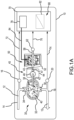
FIG. 1A is a schematic of a hydraulic fluid system that uses a hydraulic motor, gear box, and separate MRF brake, in accordance with various embodiments; -
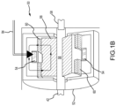
FIG. 1B is an enlarged view of the MRF brake used by the hydraulic fluid system shown inFIG. 1A ; -
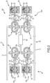
FIG. 2 is a schematic of a hydraulic fluid system that uses multiple gear boxes and MRF brakes, in accordance with various embodiments; and -
FIG. 3 is a schematic of a hydraulic fluid system that uses an integrated hydraulic motor, gear assembly, and MRF brake, in accordance with various embodiments. - The following detailed description of various embodiments herein makes reference to the accompanying drawings, which show various embodiments by way of illustration. While these various embodiments are described in sufficient detail to enable those skilled in the art to practice the disclosure, it should be understood that other embodiments may be realized and that changes may be made without departing from the scope of the disclosure. Thus, the detailed description herein is presented for purposes of illustration only and not of limitation. Furthermore, any reference to singular includes plural embodiments, and any reference to more than one component or step may include a singular embodiment or step. Also, any reference to attached, fixed, connected, or the like may include permanent, removable, temporary, partial, full or any other possible attachment option. Additionally, any reference to without contact (or similar phrases) may also include reduced contact or minimal contact. It should also be understood that unless specifically stated otherwise, references to "a," "an" or "the" may include one or more than one and that reference to an item in the singular may also include the item in the plural. Further, all ranges may include upper and lower values and all ranges and ratio limits disclosed herein may be combined.
- A hydraulic fluid system in accordance with various embodiments is illustrated in
FIG. 1A and is identified byreference numeral 10. Thehydraulic fluid system 10 includes a hydraulic motor 30 (e.g., a gear pump), areduction gear box 45, a magneto-rheological fluid (MRF)brake 50, and acontroller 70. Thehydraulic motor 30,reduction gear box 45, andMRF brake 50 are separate components in the case of thehydraulic fluid system 10, and may be disposed in spaced relation to one another. Generally, theMRF brake 50 may be operated to control a magnitude of a braking torque exerted on thehydraulic motor 30, and the magnitude of this braking torque is adjustable. The magnitude of braking torque exerted on thehydraulic motor 30 may be adjusted usingreduction gear box 45. In the case of thehydraulic fluid system 10, thehydraulic motor 30 may be characterized as an adjustable orifice for the hydraulic fluid system 10 (e.g., fluid pressure from one or more devices fluidly connected with thehydraulic motor 30 drive the hydraulic motor 30 (e.g., a gear pump 30), and theMRF brake 50 andreduction gear box 45 would in turn be used to control how thehydraulic motor 30 resists the fluid pressure from each such device). Thehydraulic motor 30,reduction gear box 45,MRF brake 50, and controller 70 collectively control the flow of thehydraulic fluid 12 within thehydraulic fluid system 10 and the pressure of thehydraulic fluid 12 within thehydraulic fluid system 10. Representative applications of thehydraulic fluid system 10 include a hydraulic damper (e.g., a shimmy damper for nose wheel steering on an aircraft, as an adjustable orifice to control the "free fall" characteristics of hydraulically-actuated landing gear for aircraft, or any other application that would benefit from having a hydraulic fluid restriction (the combination of thehydraulic motor 30,reduction gear box 45, and MRF brake 50) that can be controlled quickly and in real time. - A
hydraulic fluid 12 of any appropriate type is directed through a hydraulicfluid input line 14 and into aninput port 34 of amotor housing 32 of thehydraulic motor 30. A hydraulicfluid output line 18 extends from anoutput port 36 of themotor housing 32. The hydraulicfluid input line 14, the hydraulicfluid output line 18, or both, may be interconnected with a hydraulic fluid source, such as an accumulator, and one or more other devices. At least one pressure transducer/sensor 16 may be associated with the hydraulicfluid input line 14, at least one pressure transducer/sensor 20 may be associated with the hydraulicfluid output line 18, or both. - The
hydraulic motor 30 may include anoutput gear 38 and anidler gear 40.Hydraulic fluid 12 that enters themotor housing 32 simultaneously rotates theoutput gear 38 andidler gear 40. Anoutput shaft 42 may be interconnected and rotate with theoutput gear 38. Theoutput shaft 42 may also extend to thereduction gear box 45. - An exemplary
reduction gear box 45 is illustrated inFIG. 1A . Thereduction gear box 45 includes agear housing 44. Thegear housing 44 may be spaced from themotor housing 32. Thehydraulic fluid system 10 may also be configured such that themotor housing 32 and thegear housing 44 do not share any common housing sections. - The
reduction gear box 45 includes afirst gear 46 coupled to theoutput shaft 42 and asecond gear 47 coupled to areduction shaft 43. Thefirst gear 46 and thesecond gear 47 are contained withingear housing 44 withoutput shaft 42 andreduction shaft 43 passing throughgear housing 44. In various embodiments, more than two gears may be used, such as for example, with a planetary gear assembly, a double reduction gearbox, a right-angle worm reduction gearbox, and a helical gearbox, among others. - In the depicted embodiment,
first gear 46 is larger thansecond gear 47. The ratio of thegears gears gears gears output shaft 42 may be lower than the rotation speed of thereduction shaft 43. Similarly, the torque of theoutput shaft 42 may be higher than the torque of the reduction shaft. In various embodiments, the diameter of theoutput shaft 42 may be about the same as the diameter of thereduction shaft 43. In various embodiments, the diameter of theoutput shaft 42 may be larger than the diameter of thereduction shaft 43. In such embodiments, the difference in size between theoutput shaft 42 and thereduction shaft 43 reduces the overall weight of thehydraulic fluid system 10 as theMRF brake 50 may be smaller as well. - The
MRF brake 50 is illustrated inFIG. 1A and1B . TheMRF brake 50 includes abrake housing 52. Thebrake housing 52 may be spaced from thegear housing 44. Thehydraulic fluid system 10 may also be configured such that thegear housing 44 andbrake housing 52 do not share any common housing section. In various embodiments, thehydraulic fluid system 10 may be configured such thatgear housing 44 andbrake housing 52 share at least one common housing section. In various embodiments, theMRF brake 50 and thereduction gear box 45 are combined into a single unit sharing a housing, eithergear housing 44 orbrake housing 52. - The
MRF brake 50 includes amagnetic coil 54, arotor 56, and arotor shaft 58. Thereduction shaft 43 of thereduction gear box 45 may be coupled with therotor shaft 58 of theMRF brake 50 such that thereduction shaft 43,rotor shaft 58, androtor 56 collectively rotate at a common rotational speed (withrotor 56 androtor shaft 58 being rotatable relative to the brake housing 52). A speed transducer/sensor 62 may be associated with the rotor shaft 58 (e.g., to monitor a rotational speed of the rotor shaft 58). - At least a portion of at least one of the
rotor 56 androtor shaft 58 may be exposed to a magneto-rheological fluid 60, including with therotor 56 is disposed in the magneto-rheological fluid 60. A fixed quantity of the magneto-rheological fluid 60 may be contained/retained within thebrake housing 52. Stated another way, the magneto-rheological fluid 60 may be incorporated so as to not be recirculated through the brake housing 52 (e.g., the magneto-rheological fluid 60 does not flow from a fluid source (e.g., an accumulator) through one or more input ports of thebrake housing 52, and then exit thebrake housing 52 through one or more output ports and then back to the fluid source during operation of the MRF brake 50). - The
controller 70 may be operatively interconnected with theMRF brake 50 by an electricalsignal control line 84 that extends from thecontroller 70 to themagnetic coil 54 of theMRF brake 50. Generally, an electrical control signal is sent from thecontroller 70 to themagnetic coil 54 via thecontrol line 84. Increasing the current of this electrical control signal increases the viscosity of the magneto-rheological fluid 60 in theMRF brake 50, which increases the braking torque applied by theMRF brake 50 to thereduction shaft 43 of thereduction gear box 45. Similarly, decreasing the current of this electrical control signal decreases the viscosity of the magneto-rheological fluid 60 in theMRF brake 50, which decreases the braking torque applied by theMRF brake 50 to thereduction shaft 43 of thereduction gear box 45 with a corresponding decrease in braking to thehydraulic motor 30. - A high
pressure signal line 72 may extend from thepressure transducer 16 of thehydraulic motor 30 to the controller 70 (an input to the controller 70). A lowpressure signal line 74 may extend from thepressure transducer 20 of thehydraulic motor 30 to the controller 70 (an input to the controller 70). A rotationalspeed signal line 76 may extend from the speed transducer/sensor 62 to thecontroller 70. - The
controller 70 may be configured to utilize a pressure control logic. The monitored pressure on the input side of the hydraulic motor 30 (via pressure transducer 16) and the monitored pressure on the output side of the hydraulic motor 30 (via pressure transducer 20) may be used to determine a corresponding differential pressure between the input side and output side of thehydraulic motor 30, and this differential pressure may be used to generate an electrical control signal that provides a corresponding braking torque. A data structure 82 (e.g., a look-up table) in memory 80 (e.g., computer-readable) may correlate a certain differential pressure to a braking torque and an associated current for the electrical control signal. - System program instructions and/or controller instructions may be loaded onto a non-transitory, tangible computer-readable medium having instructions stored thereon that, in response to execution by a controller, cause the controller to perform various operations. The term "non-transitory" is to be understood to remove only propagating transitory signals per se from the claim scope and does not relinquish rights to all standard computer-readable media that are not only propagating transitory signals per se.
- An
MRF brake driver 78 of thecontroller 70 may generate and send an electrical control signal to thecoil 54 of the MRF brake 50 (via the electrical signal control line 84) that yields the desired differential pressure (between the input side and output side of the hydraulic motor 30) and a corresponding desired braking torque (via producing a certain viscosity of the magneto-rheological fluid 60 via the current of the electrical control signal). - The
controller 70 could also be configured to utilize a flow control logic. The flow rate through thehydraulic motor 30 may be correlated to a differential pressure between the input side of the hydraulic motor 30 (via pressure transducer 16) and the output side of the hydraulic motor 30 (via pressure transducer 20). The data structure 82 (e.g., a look-up table) inmemory 80 may correlate a certain rotational speed of therotor shaft 58 to a braking torque and an associated current for the electrical control signal. TheMRF brake driver 78 of thecontroller 70 may generate and send an electrical control signal to thecoil 54 of the MRF brake 50 (via the control line 84) that yields a desired rotational speed of therotor shaft 58 and a corresponding desired braking torque (via producing a certain viscosity of the magneto-rheological fluid 60 via the current of the electrical control signal). - Generally, the flow rate of the
hydraulic fluid system 10 is limited by the practical speed limit of thehydraulic motor 30. This dictates the minimal motor displacement and the torque, size, and weight of theMRF brake 50. Thereduction gear box 45 overcomes this limitation and reduces the size of theMRF brake 50 for a given application. Thereduction gear box 45 allows thehydraulic motor 30 to operate at lower speeds while reducing the braking torque of theMRF brake 50. This allows theMRF brake 50 to be smaller than otherwise possible by utilizing the higher torque-to-weight ratio of thereduction gear box 45. Therefore, while thereduction gear box 45 adds additional weight, the corresponding reduction inMRF brake 50 weight offsets the additional weight and provides improved performance. - A hydraulic fluid system in accordance with various embodiments is illustrated in
FIG. 2 and is identified byreference numeral 90. Thehydraulic fluid system 90 includes four motor/gear/brake sets brake sets FIGS. 1 and1B . The motor/gear/brake sets 92a and 92b are disposed in series with one another, the motor/gear/brake sets 92c and 92d are disposed in series with one another, and the motor/gear/brake sets brake sets coil 54 of the fourMRF brakes 50. - The hydraulic fluid input line 14' extends to the
input port 34 of thehydraulic motor 30 of the motor/gear/brake sets output port 36 of thehydraulic motor 30 of the motor/gear/brake sets 92b, 92d. Ahydraulic line 94a extends from theoutput port 36 of thehydraulic motor 30 for the motor/gear/brake set 92a to theinput port 34 of thehydraulic motor 30 for the motor/gear/brake set 92b, and also extends to ahydraulic load 96. Ahydraulic line 94b extends from theoutput port 36 of thehydraulic motor 30 for the motor/gear/brake set 92c to theinput port 34 of thehydraulic motor 30 for the motor/gear/brake set 92d, and also extends to the hydraulic load 96 (via an electrical control signal via the corresponding control line 84). - In the case of the
hydraulic fluid system 90, the pressure in the hydraulic fluid input line 14' may be constant, and the pressure in the hydraulic fluid output line 18' may be constant. The motor/gear/brake sets hydraulic fluid system 90 may be used to control thehydraulic load 96. Representativehydraulic loads 96 include without limitation an aircraft component. Thehydraulic load 96 may be a hydraulic actuator (e.g., a wheel brake actuator of an aircraft to control brake torque), a hydraulic (rotary) motor that drives an actuator, a vehicle, or any other device that requires the conversion of hydraulic power (the product of flow and pressure) into another form of mechanical (motive) energy. - A hydraulic fluid system in accordance with various embodiments is illustrated in
FIG. 3 and is identified byreference numeral 100. Generally, a hydraulic motor or gear pump (e.g., hydraulic motor 30), a gear assembly (e.g., reduction gear box 45), and an MRF brake (e.g., MRF brake 50) are integrated into acommon housing assembly 102. Thishousing assembly 102 includes agear pump housing 104, abrake housing 120, and acover plate 122. Thebrake housing 120 includes components for a gear assembly (e.g., reduction gear box 45) and an MRF brake (e.g., MRF brake 50), and furthermore closes an open end of thegear pump housing 104. Thecover plate 122 seals an open end of thebrake housing 120. The gear pump (e.g., hydraulic motor 30) includes anoutput gear 106 and anidler gear 110. Anidler gear shaft 112 is associated and rotates with theidler gear 110. Ashaft 108 is associated and rotates with each of the output gear 106 (gear pump) and a rotor 126 (gear assembly/MRF brake).Bearings 114 may rotatably support theshaft 108 and theidler gear shaft 112. Aseal 116 may be mounted on theshaft 108 adjacent to thebrake housing 120 and into which theshaft 108 extends. Amagnetic coil 124 may be disposed within thebrake housing 120, along with a magneto-rheological fluid 128 in which therotor 126 is disposed. Two or more gears may be disposed within the brake housing, forming the gear assembly. An electrical control signal to themagnetic coil 124 may be used to control the braking torque exerted by the magneto-rheological fluid 128 on gear assembly and in turn on the rotor 126 (and any portion of theshaft 108 that also interfaces with this magneto-rheological fluid 128. Increasing the current of the electrical control signal to themagnetic coil 124 increases the viscosity of the magneto-rheological fluid 128, and thereby the increases the magnitude of the braking torque exerted by the magneto-rheological fluid 128 on therotor 126, as translated through the gear assembly. Decreasing the current of the electrical control signal to themagnetic coil 124 decreases the viscosity of the magneto-rheological fluid 128, and thereby decreases the magnitude of the braking torque exerted by the magneto-rheological fluid 128 on therotor 126, as translated through the gear assembly. - Benefits, other advantages, and solutions to problems have been described herein with regard to specific embodiments. Furthermore, the connecting lines shown in the various figures contained herein are intended to represent exemplary functional relationships and/or physical couplings between the various elements. It should be noted that many alternative or additional functional relationships or physical connections may be present in a practical system. However, the benefits, advantages, solutions to problems, and any elements that may cause any benefit, advantage, or solution to occur or become more pronounced are not to be construed as critical, required, or essential features or elements of the disclosure. The scope of the disclosure is accordingly to be limited by nothing other than the appended claims, in which reference to an element in the singular is not intended to mean "one and only one" unless explicitly so stated, but rather "one or more." Moreover, where a phrase similar to "at least one of A, B, or C" is used in the claims, it is intended that the phrase be interpreted to mean that A alone may be present in an embodiment, B alone may be present in an embodiment, C alone may be present in an embodiment, or that any combination of the elements A, Band C may be present in a single embodiment; for example, A and B, A and C, B and C, or A and B and C. Different cross-hatching is used throughout the figures to denote different parts but not necessarily to denote the same or different materials.
- Systems, methods and apparatus are provided herein. In the detailed description herein, references to "one embodiment," "an embodiment," "various embodiments," etc., indicate that the embodiment described may include a particular feature, structure, or characteristic, but every embodiment may not necessarily include the particular feature, structure, or characteristic. Moreover, such phrases are not necessarily referring to the same embodiment. Further, when a particular feature, structure, or characteristic is described in connection with an embodiment, it is submitted that it is within the knowledge of one skilled in the art to affect such feature, structure, or characteristic in connection with other embodiments whether or not explicitly described. After reading the description, it will be apparent to one skilled in the relevant art(s) how to implement the disclosure in alternative embodiments.
- Numbers, percentages, or other values stated herein are intended to include that value, and also other values that are about or approximately equal to the stated value, as would be appreciated by one of ordinary skill in the art encompassed by various embodiments of the present disclosure. A stated value should therefore be interpreted broadly enough to encompass values that are at least close enough to the stated value to perform a desired function or achieve a desired result. The stated values include at least the variation to be expected in a suitable industrial process, and may include values that are within 10%, within 5%, within 1%, within 0.1%, or within 0.01% of a stated value. Additionally, the terms "substantially," "about" or "approximately" as used herein represent an amount close to the stated amount that still performs a desired function or achieves a desired result. For example, the term "substantially," "about" or "approximately" may refer to an amount that is within 10% of, within 5% of, within 1% of, within 0.1 % of, and within 0.01% of a stated amount or value.
- Finally, it should be understood that any of the above described concepts can be used alone or in combination with any or all of the other above described concepts. Although various embodiments have been disclosed and described, one of ordinary skill in this art would recognize that certain modifications would come within the scope of the invention as defined by the claims.
Claims (15)
- A hydraulic fluid system, comprising:a hydraulic motor (30) including an output shaft (42);a reduction gear box (45) having a first side and an opposing second side, the reduction gear box being coupled to the output shaft at the first side and coupled to a reduction shaft (43) at the second side; anda magneto-rheological fluid brake, MRF, brake (50) coupled to the reduction shaft.
- The hydraulic fluid system of claim 1, wherein the hydraulic motor further comprises:an idler gear (40); andan output gear (38), the output gear being coupled to the output shaft (42).
- The hydraulic fluid system of claim 1, wherein the reduction gear box further comprises:a first gear (46) coupled to the output shaft; anda second gear (47) configured to operate with the first gear, the second gear being coupled to the reduction shaft, and optionally wherein the reduction gear box has a reduction ratio of about 2:1 to about 20:1.
- The hydraulic fluid system of claim 1, wherein the reduction gear box further comprises a planetary gear having an input coupled to the output shaft and an output coupled to the reduction shaft.
- The hydraulic fluid system of any preceding claim, wherein the output shaft (42) has a first diameter and the reduction shaft (43) has a second diameter, the second diameter being smaller than the first diameter.
- The hydraulic fluid system of any preceding claim, wherein the hydraulic motor, the reduction gear box, and the MRF brake define a first set, the hydraulic fluid system further comprising:a second hydraulic motor;a second reduction gear box coupled to the second hydraulic motor; anda second MRF brake coupled to the second reduction gear box, wherein the second hydraulic motor, the second reduction gear box, and the second MRF brake define a second set, and wherein the first set and the second set are connected in series.
- The hydraulic fluid system of any preceding claim, wherein the MRF brake comprises a controller (70) configured to receive an input based on the operation of the hydraulic motor.
- The hydraulic fluid system of any preceding claim, further comprising:a first housing (44) enclosing the hydraulic motor; anda second housing (52) enclosing the reduction gear box and the MRF brake, the first housing being completely separate from the second housing.
- A hydraulic fluid system, comprising:a hydraulic motor having a first output shaft;a gear box having a second output shaft, the gear box being coupled to the first output shaft; anda magneto-rheological fluid, MRF, brake having a third output shaft, the MRF brake being coupled to the second output shaft.
- The hydraulic fluid system of claim 9, further comprising:a speed sensor (62) associated with the third output shaft; anda controller configured to receive input from the speed sensor and control the MRF brake in response to the input received from the speed sensor.
- The hydraulic fluid system of claim 9 or 10, wherein the gear box further comprises:an input gear coupled to the first output shaft; andan output gear coupled to the input gear, wherein the output gear is configured to drive the second output shaft., and optionally wherein the input gear is larger than the output gear, and further optionally wherein the ratio of the input gear to the output gear is about 5:1 to about 10:1.
- The hydraulic fluid system of claim 11, wherein the input gear and the output gear are part of a planetary gear.
- The hydraulic fluid system of any of claims 9 to 12, further comprising:a first housing enclosing the gear box and the MRF brake; anda second housing enclosing the first housing and the hydraulic motor and/or wherein the first output shaft has a first diameter, wherein the second output shaft has a second diameter, and wherein the first diameter is larger than the second diameter.
- A hydraulic fluid system, comprising:a hydraulic motor configured;a reduction gear assembly including an input gear and an output gear operatively coupled to the hydraulic motor;a magneto-rheological fluid, MRF, brake operatively coupled to the hydraulic motor through the reduction gear assembly; anda controller configured to control a braking torque of the MRF brake to manage a speed of the hydraulic motor.
- The hydraulic fluid system of claim 14, wherein a ratio of input gear to the output gear is greater than 2:1, or wherein a ratio of input gear to the output gear is about 3:1 to about 15:1.
Applications Claiming Priority (1)
| Application Number | Priority Date | Filing Date | Title |
|---|---|---|---|
| US17/723,891 US11920615B2 (en) | 2022-04-19 | 2022-04-19 | Hydraulic fluid flow control |
Publications (2)
| Publication Number | Publication Date |
|---|---|
| EP4265942A1 true EP4265942A1 (en) | 2023-10-25 |
| EP4265942B1 EP4265942B1 (en) | 2026-04-01 |
Family
ID=86095691
Family Applications (1)
| Application Number | Title | Priority Date | Filing Date |
|---|---|---|---|
| EP23168815.1A Active EP4265942B1 (en) | 2022-04-19 | 2023-04-19 | Hydraulic fluid flow control |
Country Status (4)
| Country | Link |
|---|---|
| US (1) | US11920615B2 (en) |
| EP (1) | EP4265942B1 (en) |
| BR (1) | BR102023007099A2 (en) |
| CA (1) | CA3195896A1 (en) |
Citations (3)
| Publication number | Priority date | Publication date | Assignee | Title |
|---|---|---|---|---|
| US20110045932A1 (en) * | 2008-03-27 | 2011-02-24 | Societe De Commercialisation Des Produits De La Recherche Appliquee-Socpra | Dual differential semi-active actuator fit for interaction tasks and fast motion |
| CN109941902A (en) * | 2019-02-27 | 2019-06-28 | 浙江润华机电有限公司 | a hydraulic winch |
| EP3896315A1 (en) * | 2020-04-15 | 2021-10-20 | Goodrich Corporation | Hydraulic fluid flow control |
Family Cites Families (15)
| Publication number | Priority date | Publication date | Assignee | Title |
|---|---|---|---|---|
| JP2599602B2 (en) | 1987-11-02 | 1997-04-09 | 株式会社ブリヂストン | Exciter |
| US5161653A (en) | 1989-04-18 | 1992-11-10 | Hare Sr Nicholas S | Electro-rheological shock absorber |
| US6352143B1 (en) * | 2000-03-09 | 2002-03-05 | Bridgestone/Firestone, Inc. | Vibration damping system using a hydraulic damper with a field responsive fluid control |
| US6854573B2 (en) | 2001-10-25 | 2005-02-15 | Lord Corporation | Brake with field responsive material |
| US6910699B2 (en) | 2003-05-30 | 2005-06-28 | Deere & Company | Magnetorheological fluid brake and force-feedback system for a steering mechanism |
| FR2911658B1 (en) | 2007-01-22 | 2009-04-24 | Poclain Hydraulics Ind Soc Par | DEVICE FOR HYDROSTATIC TRANSMISSION OF A GEAR. |
| JP5397411B2 (en) * | 2011-05-17 | 2014-01-22 | 株式会社日本自動車部品総合研究所 | Fluid brake device and valve timing adjusting device |
| CN204355018U (en) * | 2014-12-30 | 2015-05-27 | 齐齐哈尔大学 | A kind of auxiliary brake be used in the long descending process of heavy-load automobile |
| KR102095094B1 (en) | 2015-05-29 | 2020-03-30 | 히다치 오토모티브 시스템즈 가부시키가이샤 | Vibration damping device |
| CN107850148B (en) | 2015-07-29 | 2020-02-07 | 埃索欧耐迪克超动力 | Manually actuated brake system using magnetorheological fluid clutch apparatus |
| DE102015117594A1 (en) * | 2015-10-15 | 2017-04-20 | Inventus Engineering Gmbh | rotary damper |
| JP6953069B2 (en) | 2016-06-30 | 2021-10-27 | 株式会社栗本鐵工所 | Ferrofluid unit |
| CN206386221U (en) * | 2016-09-26 | 2017-08-08 | 中石化石油工程技术服务有限公司 | Rotary well bore sidewall core taker and gear type motor |
| CN107355490A (en) | 2017-09-14 | 2017-11-17 | 合肥工业大学 | A kind of magnetorheological transmission brake-by-wire device |
| US10677087B2 (en) | 2018-05-11 | 2020-06-09 | General Electric Company | Support structure for geared turbomachine |
-
2022
- 2022-04-19 US US17/723,891 patent/US11920615B2/en active Active
-
2023
- 2023-04-12 CA CA3195896A patent/CA3195896A1/en active Pending
- 2023-04-14 BR BR102023007099-0A patent/BR102023007099A2/en unknown
- 2023-04-19 EP EP23168815.1A patent/EP4265942B1/en active Active
Patent Citations (3)
| Publication number | Priority date | Publication date | Assignee | Title |
|---|---|---|---|---|
| US20110045932A1 (en) * | 2008-03-27 | 2011-02-24 | Societe De Commercialisation Des Produits De La Recherche Appliquee-Socpra | Dual differential semi-active actuator fit for interaction tasks and fast motion |
| CN109941902A (en) * | 2019-02-27 | 2019-06-28 | 浙江润华机电有限公司 | a hydraulic winch |
| EP3896315A1 (en) * | 2020-04-15 | 2021-10-20 | Goodrich Corporation | Hydraulic fluid flow control |
Also Published As
| Publication number | Publication date |
|---|---|
| US20230332627A1 (en) | 2023-10-19 |
| CA3195896A1 (en) | 2023-10-19 |
| BR102023007099A2 (en) | 2023-10-24 |
| US11920615B2 (en) | 2024-03-05 |
| EP4265942B1 (en) | 2026-04-01 |
Similar Documents
| Publication | Publication Date | Title |
|---|---|---|
| US10030755B2 (en) | Torque vectoring device | |
| JP5179280B2 (en) | Apparatus for transmitting torque from vehicle drive train to vehicle wheels and method for transmitting torque to vehicle drive components | |
| JP5265981B2 (en) | Apparatus for transmitting torque from a vehicle drive train to a plurality of wheels of a vehicle and method for transmitting torque to at least two vehicle drive components | |
| KR101097531B1 (en) | Drive force adjustment appapatus | |
| JP6309956B2 (en) | Vehicle equipped with hydraulic assist by torque transmission from drive shaft to drive shaft | |
| JP2015527247A (en) | Control surface actuation assembly | |
| US3461744A (en) | Steering of tracked vehicles | |
| CN103195901A (en) | Magneto-rheological clutching, braking, veering and variable speed controlling transmission assembly device | |
| US7322898B2 (en) | Active front steering actuator | |
| EP3896315B1 (en) | Hydraulic fluid flow control | |
| US9945466B2 (en) | Active differential and motor vehicle | |
| CN107850148A (en) | Use the manual actuating type brakes of magneto-rheological fluid clutch apparatus | |
| EP3099932B1 (en) | A hydraulic pump assembly for a vehicle | |
| US11920615B2 (en) | Hydraulic fluid flow control | |
| WO2002099312A1 (en) | A planetary gear unit | |
| WO2014005060A1 (en) | Electric motor/generator power transfer unit | |
| JP7023385B2 (en) | Variable line speed deceleration clutch | |
| CN116513452A (en) | Dual-redundancy electromechanical actuating front wheel turning device for unmanned aerial vehicle | |
| US11584517B2 (en) | Nose-wheel steering system | |
| US10744985B2 (en) | Electro-hydrostatic brake control | |
| EP3006284B1 (en) | Electric brake control system | |
| EP4183680B1 (en) | Feel adjustment braking systems and methods | |
| Nordhammer et al. | Controlling the slewing motion of hydraulically actuated cranes using sequential activation of counterbalance valves | |
| US20240263696A1 (en) | Control device for gearbox | |
| CN215980760U (en) | Control device for gear box |
Legal Events
| Date | Code | Title | Description |
|---|---|---|---|
| STAA | Information on the status of an ep patent application or granted ep patent |
Free format text: STATUS: THE APPLICATION HAS BEEN PUBLISHED |
|
| PUAI | Public reference made under article 153(3) epc to a published international application that has entered the european phase |
Free format text: ORIGINAL CODE: 0009012 |
|
| AK | Designated contracting states |
Kind code of ref document: A1 Designated state(s): AL AT BE BG CH CY CZ DE DK EE ES FI FR GB GR HR HU IE IS IT LI LT LU LV MC ME MK MT NL NO PL PT RO RS SE SI SK SM TR |
|
| STAA | Information on the status of an ep patent application or granted ep patent |
Free format text: STATUS: REQUEST FOR EXAMINATION WAS MADE |
|
| 17P | Request for examination filed |
Effective date: 20240424 |
|
| RBV | Designated contracting states (corrected) |
Designated state(s): AL AT BE BG CH CY CZ DE DK EE ES FI FR GB GR HR HU IE IS IT LI LT LU LV MC ME MK MT NL NO PL PT RO RS SE SI SK SM TR |
|
| STAA | Information on the status of an ep patent application or granted ep patent |
Free format text: STATUS: EXAMINATION IS IN PROGRESS |
|
| 17Q | First examination report despatched |
Effective date: 20250326 |
|
| GRAP | Despatch of communication of intention to grant a patent |
Free format text: ORIGINAL CODE: EPIDOSNIGR1 |
|
| STAA | Information on the status of an ep patent application or granted ep patent |
Free format text: STATUS: GRANT OF PATENT IS INTENDED |
|
| RIC1 | Information provided on ipc code assigned before grant |
Ipc: F16H 61/44 20060101AFI20251024BHEP Ipc: F16H 57/00 20120101ALI20251024BHEP Ipc: F16H 47/02 20060101ALI20251024BHEP Ipc: B60T 10/04 20060101ALI20251024BHEP |
|
| INTG | Intention to grant announced |
Effective date: 20251107 |
|
| GRAS | Grant fee paid |
Free format text: ORIGINAL CODE: EPIDOSNIGR3 |
|
| GRAA | (expected) grant |
Free format text: ORIGINAL CODE: 0009210 |
|
| STAA | Information on the status of an ep patent application or granted ep patent |
Free format text: STATUS: THE PATENT HAS BEEN GRANTED |
|
| AK | Designated contracting states |
Kind code of ref document: B1 Designated state(s): AL AT BE BG CH CY CZ DE DK EE ES FI FR GB GR HR HU IE IS IT LI LT LU LV MC ME MK MT NL NO PL PT RO RS SE SI SK SM TR |
|
| REG | Reference to a national code |
Ref country code: CH Ref legal event code: F10 Free format text: ST27 STATUS EVENT CODE: U-0-0-F10-F00 (AS PROVIDED BY THE NATIONAL OFFICE) Effective date: 20260401 Ref country code: GB Ref legal event code: FG4D |
|
| REG | Reference to a national code |
Ref country code: DE Ref legal event code: R096 Ref document number: 602023014301 Country of ref document: DE |
|
| REG | Reference to a national code |
Ref country code: IE Ref legal event code: FG4D |