EP4265931A1 - Asymmetric mechanical torque limiter - Google Patents
Asymmetric mechanical torque limiter Download PDFInfo
- Publication number
- EP4265931A1 EP4265931A1 EP22305598.9A EP22305598A EP4265931A1 EP 4265931 A1 EP4265931 A1 EP 4265931A1 EP 22305598 A EP22305598 A EP 22305598A EP 4265931 A1 EP4265931 A1 EP 4265931A1
- Authority
- EP
- European Patent Office
- Prior art keywords
- torque
- annular friction
- disk
- skewed
- friction disk
- Prior art date
- Legal status (The legal status is an assumption and is not a legal conclusion. Google has not performed a legal analysis and makes no representation as to the accuracy of the status listed.)
- Granted
Links
Images


Classifications
-
- F—MECHANICAL ENGINEERING; LIGHTING; HEATING; WEAPONS; BLASTING
- F16—ENGINEERING ELEMENTS AND UNITS; GENERAL MEASURES FOR PRODUCING AND MAINTAINING EFFECTIVE FUNCTIONING OF MACHINES OR INSTALLATIONS; THERMAL INSULATION IN GENERAL
- F16D—COUPLINGS FOR TRANSMITTING ROTATION; CLUTCHES; BRAKES
- F16D7/00—Slip couplings, e.g. slipping on overload, for absorbing shock
- F16D7/007—Slip couplings, e.g. slipping on overload, for absorbing shock the torque being transmitted and limited by rolling surfaces skidding, e.g. skew needle rollers
-
- B—PERFORMING OPERATIONS; TRANSPORTING
- B64—AIRCRAFT; AVIATION; COSMONAUTICS
- B64C—AEROPLANES; HELICOPTERS
- B64C13/00—Control systems or transmitting systems for actuating flying-control surfaces, lift-increasing flaps, air brakes, or spoilers
- B64C13/24—Transmitting means
- B64C13/26—Transmitting means without power amplification or where power amplification is irrelevant
- B64C13/28—Transmitting means without power amplification or where power amplification is irrelevant mechanical
-
- F—MECHANICAL ENGINEERING; LIGHTING; HEATING; WEAPONS; BLASTING
- F16—ENGINEERING ELEMENTS AND UNITS; GENERAL MEASURES FOR PRODUCING AND MAINTAINING EFFECTIVE FUNCTIONING OF MACHINES OR INSTALLATIONS; THERMAL INSULATION IN GENERAL
- F16D—COUPLINGS FOR TRANSMITTING ROTATION; CLUTCHES; BRAKES
- F16D7/00—Slip couplings, e.g. slipping on overload, for absorbing shock
- F16D7/02—Slip couplings, e.g. slipping on overload, for absorbing shock of the friction type
- F16D7/024—Slip couplings, e.g. slipping on overload, for absorbing shock of the friction type with axially applied torque limiting friction surfaces
-
- F—MECHANICAL ENGINEERING; LIGHTING; HEATING; WEAPONS; BLASTING
- F16—ENGINEERING ELEMENTS AND UNITS; GENERAL MEASURES FOR PRODUCING AND MAINTAINING EFFECTIVE FUNCTIONING OF MACHINES OR INSTALLATIONS; THERMAL INSULATION IN GENERAL
- F16C—SHAFTS; FLEXIBLE SHAFTS; ELEMENTS OR CRANKSHAFT MECHANISMS; ROTARY BODIES OTHER THAN GEARING ELEMENTS; BEARINGS
- F16C19/00—Bearings with rolling contact, for exclusively rotary movement
- F16C19/22—Bearings with rolling contact, for exclusively rotary movement with bearing rollers essentially of the same size in one or more circular rows, e.g. needle bearings
- F16C19/30—Bearings with rolling contact, for exclusively rotary movement with bearing rollers essentially of the same size in one or more circular rows, e.g. needle bearings for axial load mainly
Definitions
- the present disclosure relates to torque limiters and in particular an asymmetric torque limiter.
- a torque limiter is a device that provides a limit to the torque that can be transmitted by a connection, for example between an input and an output shaft. This limiting of the transmissible torque through the connection is able to protect components either comprised by or connected to the connection from mechanical overload and thereby reduce the chance of damage incurred by the overload.
- a torque limiter may be used to limit torque in both directions of torque, that is, in both a clockwise and an anticlockwise direction.
- the transmissible torque limit may be different in each rotational direction.
- An asymmetric torque limiter is a torque limiter with a different transmissible torque limit in each torque direction.
- the torque that can be transmitted through the asymmetric torque limiter may be higher in a clockwise direction than in an anticlockwise direction.
- Asymmetric torque limiters may be used in a variety of applications.
- One such application is in the actuation of flight control surfaces (such as flaps, slats, spoilers, ailerons, and/or spoilerons) on an aircraft, for example on a wing of the aircraft.
- the flight control surfaces, and their actuators experience differing loads during extension (or deployment) and retraction due to the airflow interacting with the flight control surface. Greater torque is required to extend or deploy the flight control surface than to retract the flight control surface. There is therefore a requirement for a higher transmissible torque limit in the direction which deploys the flight control surface than the transmissible torque limit in the direction which retracts the flight control surface.
- an asymmetric torque limiter having an axis of rotation including a first annular friction disk, a second annular friction disk, a skewed roller disk, a first resilient member and a second resilient member.
- the second annular friction disk is concentrically arranged with the first annular friction disk.
- the skewed roller disk is in contact with the second annular friction disk.
- the skewed roller disk includes a plurality of skewed rollers mounted in an annular retainer.
- the plurality of skewed rollers are each rotatable about a respective roller axis, each roller axis being skewed with respect to a radial direction passing through the skewed roller from the axis of rotation.
- the first resilient member is attached to the first annular friction disk and is configured to bias the first annular friction disk toward an input shaft.
- the second resilient member is configured to bias the skewed roller disk toward the second annular friction disk.
- the asymmetric torque limiter may include an annular spacer mounted between the second resilient member and the skewed roller disk.
- the annular spacer is in contact with the skewed roller disk.
- the second annular friction disk is arranged radially outwardly of first annular friction disk.
- the second annular friction disk is arranged radially inwardly of the first annular friction disk.
- the first resilient member includes a Belleville spring.
- the second resilient member includes a Belleville spring.
- each of the first and the second annular friction disks are carbon friction disks.
- each roller axis is skewed at an angle of 45 degrees with respect to the radial direction passing through the skewed roller from the axis of rotation (A).
- an assembly including an input shaft, an output shaft coaxial with the input shaft and an asymmetric torque limiter in accordance with any of the above mounted axially between the input shaft and the output shaft.
- the output shaft includes an outer circumferential ring located radially outwardly of the skewed roller disk.
- the assembly includes a static body and a thrust bearing mounted axially between a portion of the static body and a portion of the input shaft.
- an aircraft wing including a flight control surface and the assembly of any of the above.
- the output shaft is configured to actuate the flight control surface.
- the method includes: providing an input shaft with a first input torque in one of a clockwise and anticlockwise direction and transmitting the first input torque from the input shaft to an output shaft when the first input torque is less than a first torque threshold and preventing transmission of torque higher than the first torque threshold when the first input torque is greater than the first torque threshold; and providing the input shaft with a second input torque in the other of the clockwise and anticlockwise direction and transmitting the second input torque from the input shaft to the output shaft when the second input torque is less than a second torque threshold and preventing transmission of torque higher than the second torque threshold when the second input torque is greater than the second torque threshold.
- the second torque threshold is larger than the first torque threshold.
- a method of controlling a flight control surface on an aircraft wing including the method above, wherein providing the input shaft with the second input torque deploys the flight control surface and providing the input shaft with the first input torque retracts the flight control surface.
- the aircraft 2 includes wings 4 and a tail assembly 6 including a vertical stabiliser 8 and horizontal stabilisers 10.
- the illustrated wings 4 and the tail assembly 6 include flight control surfaces 12, 14, 15, 16, 18, 20 which include ailerons 12, flaps 14, slats 15, spoilers 16, elevators 18 and a rudder 20.
- flight control surfaces 12-20 are extended (or deployed), retracted and adjusted as appropriate to control the yaw 22, the roll 24, the pitch 26, and the lift 28 of the aircraft 2 when in flight by the interaction of the flight control surfaces 12-20 with the airflow.
- the asymmetric torque limiter allows torque to be transmitted therethrough when the input torque is below a threshold torque.
- the threshold torque in the extension direction is greater than the threshold torque in the retraction direction.
- the asymmetric torque limiter allows the transmission of a greater torque in the extension direction than in the retraction direction.
- the extension direction corresponds to one of a clockwise and anti-clockwise direction and the retraction direction corresponds to the other of the clockwise and anticlockwise direction of input torque, depending on the configuration of the actuator.
- An asymmetric torque limiter 30 is described below with reference to figure 2 .
- the illustrated asymmetric torque limiter 30 is provided between an input shaft 32 and an output shaft 34.
- the input shaft 32 and output shaft 34 are arranged coaxially on an axis of rotation A.
- the output shaft 34 is located in a distal direction with respect to the input shaft 32.
- the input shaft 32 is supported by a stationary casing 36 (or a body) by means of thrust bearings 38.
- the thrust bearings 38 are located axially between a portion of the casing 36 and a portion 40 of the input shaft 32.
- the portion 40 of the input shaft 32 is a radially extending flange 40 at a distal end of the input shaft 32.
- the thrust bearings 38 may have any appropriate construction, such as roller bearings supported by distal and proximal races attached to the portion 40 of the input shaft 32 and the portion of the casing 36 respectively.
- Alternative thrust bearings may be used, such as a three-part ball thrust bearing.
- the thrust bearing 38 allows the input shaft 32 to rotate with minimal friction with respect to the casing 36 and supports a predominantly axial load between the input shaft 34 and the casing 36.
- the first annular friction disk 42 is mounted to a first resilient member 44, and biased by the first resilient member 44 toward the input shaft 32 to be in contact therewith.
- the first resilient member is mounted to the output shaft 34.
- the first resilient member 44 may be a spring, for example a Belleville spring 44 (which is a plurality of stacked Belleville washers, or stacked coned-disc springs).
- the illustrated first resilient member 44 is coaxial to the axis of rotation A.
- the friction coefficient may be from 0.05 to 0.2, or more particularly about 0.1.
- the spring load may be 2000-4000 N, or more particularly about 2800 N.
- the inner radius R 1 may be from 1 mm to 10mm, or more particularly about 5 mm.
- the outer radius R 2 may be from 10 mm to 60 mm, or more particularly about 30 mm.
- the first individual torque threshold may be from 2 Nm to 8 Nm, or more particularly about 4.9 Nm.
- the first annular friction disk 42 would allow torque in both clockwise and anticlockwise directions to be transmitted therethrough from the input shaft 32 to the output shaft 34 when the torque input to the input shaft 32 is below the first individual torque threshold and prevent any further torque being transmitted when the torque input to the input shaft 32 is above the first individual torque threshold.
- the input shaft 32 will slip with respect to the first annular friction disk 42 and thereby rotate without transmitting all of the input torque.
- the asymmetric torque limiter 30 also includes a second annular friction disk 46 located between the input shaft 32 and the output shaft 34.
- the second annular friction disk 46 is arranged coaxially about the axis of rotation A.
- the illustrated second annular friction disk 46 is located radially outwards of the first annular friction disk 42.
- the second annular friction disk 46 in some embodiments is a carbon friction disk; however, other materials may be used for the second annular friction disk 46.
- Axially adjacent (with respect to the rotational axis A) to the second annular friction disk 46 is a skewed roller disk 48, distal of the second annular friction disk 46.
- the skewed roller disk 48 includes an annular retainer 50 and a plurality of skewed rollers 52.
- the skewed rollers 52 are mounted in the annular retainer 50 in a manner such that each skewed roller 52 may freely rotate about a respective roller axis 54.
- each respective roller axis 54 is arranged at an angle ⁇ with respect to a radial direction 56 of the skewed roller disk 48 extending through the centre of the respective skewed roller 52.
- the angle ⁇ may be called a skew angle or a tilt angle.
- the angle ⁇ is an acute angle. In some embodiments the angle ⁇ is between 20 and 70 degrees, or, more particularly, between 30 and 60 degrees, or about 45 degrees.
- a second resilient member 60 is arranged axially adjacent the spacer 58.
- the second resilient member 60 is mounted to the output shaft 34 and biases the spacer 58 and the skewed roller disk 48 toward the second annular friction disk 46. Due to the action of the second resilient member 60 both the spacer 58 and the second annular friction disk 46 are maintained in contact with the skewed rollers 52.
- the second resilient member 60 may be a spring, for example a Belleville spring 60 (which is a plurality of stacked Belleville washers, or stacked coned-disc springs).
- the illustrated second resilient member 60 is coaxial with the rotational axis A and is arranged concentrically with the first resilient member 44.
- the illustrated output shaft 34 includes an outer circumferential ring 66 located radially outwardly of the skewed roller disk 48.
- the outer circumferential ring 66 maintains the skewed roller disk 48, the spacer 58 and the second resilient member 60 in its coaxial position about the rotation axis A.
- the second annular friction disk 46, the skewed roller disk 48, the spacer 58 and the second resilient member 60 allow the transmission of torque in a single direction below a second individual torque threshold.
- the second annular friction disk 46 will slip in the clockwise direction with respect to the skewed roller disk 48, and/or the skewed roller disk 48 will slip in the clockwise direction with respect to the spacer 58. In this case, the input shaft 32 will thereby rotate freely without transmitting all of the input torque. In this torque direction the skewed roller disk 48 is said to be in a sliding condition.
- the skewed rollers 52 are able to rotate about their roller axes 54 and thereby allow the input shaft 32 to rotate with minimal friction and thereby without driving the skewed roller disk 48 or the spacer 58 and thus the output shaft 34.
- the skewed roller disk 48 is said to be in a rolling condition.
- the second individual torque threshold is determined by certain characteristics of the second annular friction disk 46, the skewed roller disk 48 and the second resilient member 60. Those characteristics include: an inner radius R 3 of the second annular friction disk 46; an outer radius R 4 of the second annular friction disk 46, a spring load, a friction coefficient between the material of the second annular friction disk 46 and that of the skewed rollers 46, and the skew angle ⁇ of the skewed rollers 46.
- the friction coefficient may be from 0.05 to 0.2, or more particularly about 0.1.
- the spring load may be 2000-4000 N, or more particularly about 2800 N.
- the inner radius R 3 may be from 20 mm to 60mm, or more particularly about 40 mm.
- the outer radius R 4 may be from 40 mm to 80 mm, or more particularly about 52.5 mm.
- the second individual torque threshold may be from 8 Nm to 20 Nm, or more particularly about 12.95 Nm.
- first annular friction disk 42 When the first annular friction disk 42 is used in combination with the second annular friction disk 46 and the skewed roller disk 48 in the asymmetric torque limiter described herein, two load paths are provided between the input shaft 32 and the output shaft 34.
- the first load path is through the first annular friction disk 42 and the first resilient member 44 and the second load path is through the second annular friction disk 46, the skewed roller disk 48, the spacer 58 and the second resilient member 60.
- a first combined torque threshold (or a first torque threshold) below which all of the torque is transmitted to the output shaft 34 is the sum of the first individual torque threshold and the second individual torque threshold.
- a second combined torque threshold (or a second torque threshold) below which torque is transmitted to the output shaft 34 is equal to the first individual torque threshold. Accordingly, the first combined torque threshold is higher than the second combined torque threshold. This means that higher torque can be transmitted in the first (or clockwise) direction 62 than in the second (or anticlockwise) direction 64.
- the first direction 62 (with its higher torque threshold) is used for extension of the aircraft flight control surface 12-20 and the second direction 64 (with its lower torque threshold) is used for retraction of the aircraft flight control surface 12-20.
- the rolling of the skewed rollers 52 may provide a small amount of friction such that the second combined torque threshold (or second torque threshold) is slightly higher than the first individual torque threshold, for example by up to about 10%.
- the first annular friction disk 42 still accounts for 90% or more of the second combined torque threshold (or the global retraction torque threshold).
- the asymmetric torque limiter provides a passive means to limit the torque transmissible in each direction of the torque input from the input shaft 32 at different torque limits.
- FIG. 4 An alternative embodiment of an asymmetric torque limiter 30' is illustrated in figure 4 .
- Like reference numerals have been used for similar elements, and unless described otherwise below, the elements of figure 4 share the same characteristics as those of figure 2 .
- figure 4 differs from that of figure 2 in that the first annular friction disk 42' and first resilient member 44' are radially outwardly located of the second annular friction disk 46', the skewed roller disk 48', the spacer 58' and the second resilient member 60' (i.e., they have swapped positions).
- the inner radius R 1 ' and the outer radius R 2 ' of the first annular friction disk 42' are therefore larger in the figure 4 embodiment.
- the inner radius R 1 ' may be between 20 mm and 60 mm, or more particularly about 40 mm
- the outer radius R 2 ' may be between 60 mm and 80 mm, or more particularly about 52.5 mm.
- the inner radius R 3 ' and the outer radius R 4 ' of the second annular friction disk 46' will likewise be smaller in the figure 4 embodiment.
- the inner radius R 3 may be from 1 mm to 10mm, or more particularly about 5 mm
- the outer radius R 4 may be from 10 mm to 60 mm, or more particularly about 30 mm.
- the first resilient member 44' shown in figure 4 is still associated with the first annular friction disk 42' in the same manner as described with reference to figure 2 and is accordingly larger than the first resilient member 44 shown in figure 2 .
- the skewed roller disk 48', skewed rollers 52', retainer 50', spacer 58' and second resilient member 60' are still associated with the second annular friction disk 46' in the same manner as described with reference to figure 2 .
- Each of the skewed roller disk 48', skewed rollers 52', retainer 50', spacer 58' and second resilient member 60' are therefore smaller than their equivalent components from figure 2 .
- Each of the skewed roller disk 48', skewed rollers 52', retainer 50', spacer 58' and second resilient member 60' are arranged radially inwardly of the first resilient member 44'.
- the first individual torque threshold will be higher than the embodiment of figure 2 and the second individual torque threshold will be lower than the embodiment of figure 2 .
- the skewed roller disk 48' which provides the asymmetric character of the torque limiter, by being positioned inside the first annular friction disk 42', will provide a smaller proportion of the first combined torque threshold (that is, the torque threshold where the skewed roller disk 48' is in its sliding condition).
- the second annular friction disk 46, 46' and the spacer 58, 58' could swap positions, such that the spacer 58, 58' is mounted to the input shaft 32 and the second annular friction disk 46, 46' is mounted to the second resilient member 60, 60'.
- the torque limiting function (described above) is achieved in the same manner in each of these embodiments by the skewed roller disk 48, 48' slipping with respect to the second annular friction disk 46, 46' and/or the spacer 58, 58' when a torque exceeding the second individual torque threshold in the clockwise direction 62 is provided to the input shaft 32.
- the second annular friction disk 46, 46' may be misaligned axially with the first annular friction disk 42, 42'.
Landscapes
- Engineering & Computer Science (AREA)
- General Engineering & Computer Science (AREA)
- Mechanical Engineering (AREA)
- Automation & Control Theory (AREA)
- Aviation & Aerospace Engineering (AREA)
- One-Way And Automatic Clutches, And Combinations Of Different Clutches (AREA)
Abstract
Description
- The present disclosure relates to torque limiters and in particular an asymmetric torque limiter.
- A torque limiter is a device that provides a limit to the torque that can be transmitted by a connection, for example between an input and an output shaft. This limiting of the transmissible torque through the connection is able to protect components either comprised by or connected to the connection from mechanical overload and thereby reduce the chance of damage incurred by the overload.
- In certain applications, a torque limiter may be used to limit torque in both directions of torque, that is, in both a clockwise and an anticlockwise direction. Of those applications, the transmissible torque limit may be different in each rotational direction.
- An asymmetric torque limiter is a torque limiter with a different transmissible torque limit in each torque direction. For example, the torque that can be transmitted through the asymmetric torque limiter may be higher in a clockwise direction than in an anticlockwise direction.
- Asymmetric torque limiters may be used in a variety of applications. One such application is in the actuation of flight control surfaces (such as flaps, slats, spoilers, ailerons, and/or spoilerons) on an aircraft, for example on a wing of the aircraft. The flight control surfaces, and their actuators in turn, experience differing loads during extension (or deployment) and retraction due to the airflow interacting with the flight control surface. Greater torque is required to extend or deploy the flight control surface than to retract the flight control surface. There is therefore a requirement for a higher transmissible torque limit in the direction which deploys the flight control surface than the transmissible torque limit in the direction which retracts the flight control surface.
- In previous systems active torque limit control, for example by electronically limiting the torque in each direction, has been used. However, there is a desire for a passive, mechanical, asymmetric torque limiter, to avoid dependence on electronic controls, for example to mitigate risk arising in the event of electronic failure.
- There is also a desire to provide a compact and light asymmetric torque limiter.
- There is a desire for a passive asymmetric torque limiter having a different torque limit in each of a clockwise and anti-clockwise direction.
- While described in the context of aircraft flight control surfaces, it is noted that the presently described asymmetric torque limiter will be useful in a variety of applications.
- According to one aspect of the present disclosure, there is provided an asymmetric torque limiter having an axis of rotation including a first annular friction disk, a second annular friction disk, a skewed roller disk, a first resilient member and a second resilient member. The second annular friction disk is concentrically arranged with the first annular friction disk. The skewed roller disk is in contact with the second annular friction disk. The skewed roller disk includes a plurality of skewed rollers mounted in an annular retainer. The plurality of skewed rollers are each rotatable about a respective roller axis, each roller axis being skewed with respect to a radial direction passing through the skewed roller from the axis of rotation. The first resilient member is attached to the first annular friction disk and is configured to bias the first annular friction disk toward an input shaft. The second resilient member is configured to bias the skewed roller disk toward the second annular friction disk.
- In some examples in accordance with the above, the asymmetric torque limiter may include an annular spacer mounted between the second resilient member and the skewed roller disk. The annular spacer is in contact with the skewed roller disk.
- In some examples in accordance with any of the above, the second annular friction disk is arranged radially outwardly of first annular friction disk.
- In some examples in accordance with any of the above, the second annular friction disk is arranged radially inwardly of the first annular friction disk.
- In some examples in accordance with any of the above, the first resilient member includes a Belleville spring.
- In some examples in accordance with any of the above, the second resilient member includes a Belleville spring.
- In some examples in accordance with any of the above, each of the first and the second annular friction disks are carbon friction disks.
- In some examples in accordance with any of the above, each roller axis is skewed at an angle of 45 degrees with respect to the radial direction passing through the skewed roller from the axis of rotation (A).
- There is also provided an assembly including an input shaft, an output shaft coaxial with the input shaft and an asymmetric torque limiter in accordance with any of the above mounted axially between the input shaft and the output shaft.
- In some examples in accordance with the above, the output shaft includes an outer circumferential ring located radially outwardly of the skewed roller disk.
- In some examples in accordance with any of the above, the assembly includes a static body and a thrust bearing mounted axially between a portion of the static body and a portion of the input shaft.
- There is also provided an aircraft wing including a flight control surface and the assembly of any of the above. The output shaft is configured to actuate the flight control surface.
- There is also provided an aircraft including the aircraft wing of the above.
- There is also provided a method of passively limiting torque asymmetrically using the asymmetric torque limiter of any of the above. The method includes: providing an input shaft with a first input torque in one of a clockwise and anticlockwise direction and transmitting the first input torque from the input shaft to an output shaft when the first input torque is less than a first torque threshold and preventing transmission of torque higher than the first torque threshold when the first input torque is greater than the first torque threshold; and providing the input shaft with a second input torque in the other of the clockwise and anticlockwise direction and transmitting the second input torque from the input shaft to the output shaft when the second input torque is less than a second torque threshold and preventing transmission of torque higher than the second torque threshold when the second input torque is greater than the second torque threshold. The second torque threshold is larger than the first torque threshold.
- There is also provided a method of controlling a flight control surface on an aircraft wing including the method above, wherein providing the input shaft with the second input torque deploys the flight control surface and providing the input shaft with the first input torque retracts the flight control surface.
- The features of the above aspects and examples may be used in any combination.
- These and other features disclosed herein can be best understood from the following specification and drawings, the following of which is a brief description.
- Various embodiments of this disclosure will now be described by way of example only, with reference to the accompanying drawings in which:
-
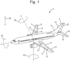
Figure 1 shows an aircraft in which the torque limiter may be used; -
Figure 2 shows a cross-sectional schematic view of an asymmetric torque limiter according to one embodiment; -
Figure 3 shows an axial view of the skewed roller device and the first and second annular friction disks of the torque limiter offigure 2 ; and -
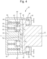
Figure 4 shows a cross-sectional schematic view of an asymmetric torque limiter according to another embodiment. - With reference to
figure 1 , there is described anaircraft 2 in which the asymmetric torque limiter is used. Theaircraft 2 includeswings 4 and a tail assembly 6 including a vertical stabiliser 8 andhorizontal stabilisers 10. - The illustrated
wings 4 and the tail assembly 6 includeflight control surfaces ailerons 12,flaps 14,slats 15,spoilers 16,elevators 18 and arudder 20. - Together, these flight control surfaces 12-20 are extended (or deployed), retracted and adjusted as appropriate to control the
yaw 22, theroll 24, thepitch 26, and thelift 28 of theaircraft 2 when in flight by the interaction of the flight control surfaces 12-20 with the airflow. - The flight control surfaces 12-20 are controlled by the action of respective actuators, which include of a motor and a gearbox. These actuators provide rotary motion as their output, which is connected to the respective flight control surface 12-20. These actuators may be suitable for use on thin wing configurations.
- There is a requirement to limit the amount of torque transmitted from the actuator to the flight control surfaces 12-20 in order to avoid mechanical overload from an input shaft working against the airflow interacting with the flight control surface 12-20. For this reason, a torque limiter is provided on the input of each flight control surface 12-20. The torque limit required is different for the extension (or deployment) of the flight control surface 12-20 and the retraction of the flight control surface 12-20. The torque required to extend (or deploy) the flight control surface 12-20 is greater than the torque required to retract the flight control surface 12-20, and thus an asymmetric torque limiter is required.
- The asymmetric torque limiter allows torque to be transmitted therethrough when the input torque is below a threshold torque.
- The threshold torque in the extension direction is greater than the threshold torque in the retraction direction. In this way, the asymmetric torque limiter allows the transmission of a greater torque in the extension direction than in the retraction direction. The extension direction corresponds to one of a clockwise and anti-clockwise direction and the retraction direction corresponds to the other of the clockwise and anticlockwise direction of input torque, depending on the configuration of the actuator.
- An
asymmetric torque limiter 30 is described below with reference tofigure 2 . - The illustrated
asymmetric torque limiter 30 is provided between aninput shaft 32 and anoutput shaft 34. Theinput shaft 32 andoutput shaft 34 are arranged coaxially on an axis of rotation A. Theoutput shaft 34 is located in a distal direction with respect to theinput shaft 32. - The
input shaft 32 is supported by a stationary casing 36 (or a body) by means ofthrust bearings 38. Thethrust bearings 38 are located axially between a portion of thecasing 36 and aportion 40 of theinput shaft 32. Theportion 40 of theinput shaft 32 is aradially extending flange 40 at a distal end of theinput shaft 32. Thethrust bearings 38 may have any appropriate construction, such as roller bearings supported by distal and proximal races attached to theportion 40 of theinput shaft 32 and the portion of thecasing 36 respectively. Alternative thrust bearings may be used, such as a three-part ball thrust bearing. Thethrust bearing 38 allows theinput shaft 32 to rotate with minimal friction with respect to thecasing 36 and supports a predominantly axial load between theinput shaft 34 and thecasing 36. - The
asymmetric torque limiter 30 includes a firstannular friction disk 42 located between theinput shaft 32 and theoutput shaft 34. The firstannular friction disk 42 is arranged coaxially about the axis of rotation A. The firstannular friction disk 42 in some embodiments is a carbon friction disk; however, other materials may be used for the firstannular friction disk 42. The firstannular friction disk 42 acts as a symmetrical torque limiter in that it provides a torque threshold (the first individual torque threshold described below) that is the same in each of a clockwise direction and an anti-clockwise direction. - In one embodiment, the first
annular friction disk 42 is mounted to a firstresilient member 44, and biased by the firstresilient member 44 toward theinput shaft 32 to be in contact therewith. The first resilient member is mounted to theoutput shaft 34. The firstresilient member 44 may be a spring, for example a Belleville spring 44 (which is a plurality of stacked Belleville washers, or stacked coned-disc springs). The illustrated firstresilient member 44 is coaxial to the axis of rotation A. - The first
annular friction disk 42 and the firstresilient member 44 have characteristics that allow a torque to be transmitted from theinput shaft 32, through the firstannular friction disk 42 and firstresilient member 44 to theoutput shaft 34, when the torque is below a first individual torque threshold. The first individual torque threshold is the same in both the clockwise and anticlockwise directions. Above the first individual torque threshold, the surface of theinput shaft 32 in contact with the firstannular friction disk 42 will slip such that any excess torque above the first individual torque threshold will not be transmitted. Those characteristics that set the first individual torque threshold include: an inner radius R1 of theannular friction disk 42; an outer radius R2 of theannular friction disk 42, a spring load, and a friction coefficient between the material of the firstannular friction disk 42 and that of theinput shaft 32. - The friction coefficient may be from 0.05 to 0.2, or more particularly about 0.1. The spring load may be 2000-4000 N, or more particularly about 2800 N. The inner radius R1 may be from 1 mm to 10mm, or more particularly about 5 mm. The outer radius R2 may be from 10 mm to 60 mm, or more particularly about 30 mm. The first individual torque threshold may be from 2 Nm to 8 Nm, or more particularly about 4.9 Nm.
- For alternative applications where different torque thresholds are required, these characteristics can be different to those listed above.
- Taken in isolation (for example if the second annular friction disk and skewed roller disk described below were removed), the first
annular friction disk 42 would allow torque in both clockwise and anticlockwise directions to be transmitted therethrough from theinput shaft 32 to theoutput shaft 34 when the torque input to theinput shaft 32 is below the first individual torque threshold and prevent any further torque being transmitted when the torque input to theinput shaft 32 is above the first individual torque threshold. When the torque input to theinput shaft 32 is above the first individual torque threshold, theinput shaft 32 will slip with respect to the firstannular friction disk 42 and thereby rotate without transmitting all of the input torque. - The
asymmetric torque limiter 30 also includes a secondannular friction disk 46 located between theinput shaft 32 and theoutput shaft 34. The secondannular friction disk 46 is arranged coaxially about the axis of rotation A. The illustrated secondannular friction disk 46 is located radially outwards of the firstannular friction disk 42. The secondannular friction disk 46 in some embodiments is a carbon friction disk; however, other materials may be used for the secondannular friction disk 46. - Axially adjacent (with respect to the rotational axis A) to the second
annular friction disk 46 is a skewedroller disk 48, distal of the secondannular friction disk 46. The skewedroller disk 48 includes anannular retainer 50 and a plurality of skewedrollers 52. As can be appreciated fromfigure 3 , the skewedrollers 52 are mounted in theannular retainer 50 in a manner such that eachskewed roller 52 may freely rotate about a respective roller axis 54. As shown, each respective roller axis 54 is arranged at an angle α with respect to aradial direction 56 of the skewedroller disk 48 extending through the centre of the respective skewedroller 52. The angle α may be called a skew angle or a tilt angle. The angle α is an acute angle. In some embodiments the angle α is between 20 and 70 degrees, or, more particularly, between 30 and 60 degrees, or about 45 degrees. - With reference again to
figure 2 , axially adjacent (with respect to the rotational axis A) to the skewedrollers 52 is aspacer 58. Thespacer 58 is distal of and in contact with the skewedrollers 52. Thespacer 58 is coaxially arranged about the rotational axis A. - A second
resilient member 60 is arranged axially adjacent thespacer 58. The secondresilient member 60 is mounted to theoutput shaft 34 and biases thespacer 58 and the skewedroller disk 48 toward the secondannular friction disk 46. Due to the action of the secondresilient member 60 both thespacer 58 and the secondannular friction disk 46 are maintained in contact with the skewedrollers 52. The secondresilient member 60 may be a spring, for example a Belleville spring 60 (which is a plurality of stacked Belleville washers, or stacked coned-disc springs). The illustrated secondresilient member 60 is coaxial with the rotational axis A and is arranged concentrically with the firstresilient member 44. - The illustrated
output shaft 34 includes an outercircumferential ring 66 located radially outwardly of the skewedroller disk 48. The outercircumferential ring 66 maintains the skewedroller disk 48, thespacer 58 and the secondresilient member 60 in its coaxial position about the rotation axis A. - Taken in isolation (that is, if the first
annular friction disk 42 were removed), the secondannular friction disk 46, the skewedroller disk 48, thespacer 58 and the secondresilient member 60 allow the transmission of torque in a single direction below a second individual torque threshold. - Considering
figure 3 , when theinput shaft 32 rotates in aclockwise direction 62 with respect to the skewed roller disk 48 (which is equivalent to the skewedroller disk 48 rotating in ananticlockwise direction 64 in the frame of reference of the input shaft 32), the skewedrollers 52 are not able to freely rotate about their roller axes 54. If the input torque is below a second individual torque threshold, the secondannular friction disk 46 will frictionally engage the skewedrollers 52 to drive rotation of the skewedroller disk 48. The skewedroller disk 48 will in turn frictionally engage and drive rotation of thespacer 58 and thus ultimately drive rotation of theoutput shaft 34. If the input torque is above the second individual torque threshold, the secondannular friction disk 46 will slip in the clockwise direction with respect to the skewedroller disk 48, and/or the skewedroller disk 48 will slip in the clockwise direction with respect to thespacer 58. In this case, theinput shaft 32 will thereby rotate freely without transmitting all of the input torque. In this torque direction the skewedroller disk 48 is said to be in a sliding condition. - When the
input shaft 32 rotates in ananti-clockwise rotation 64 with respect to the skewedroller disk 48, the skewedrollers 52 are able to rotate about their roller axes 54 and thereby allow theinput shaft 32 to rotate with minimal friction and thereby without driving the skewedroller disk 48 or thespacer 58 and thus theoutput shaft 34. In this situation the skewedroller disk 48 is said to be in a rolling condition. - As will be appreciated, if the direction of the skew of the skewed
rollers 52 is reversed, then the directions in which free rotation and torque limited transmission is allowed are also reversed. - The second individual torque threshold is determined by certain characteristics of the second
annular friction disk 46, the skewedroller disk 48 and the secondresilient member 60. Those characteristics include: an inner radius R3 of the secondannular friction disk 46; an outer radius R4 of the secondannular friction disk 46, a spring load, a friction coefficient between the material of the secondannular friction disk 46 and that of the skewedrollers 46, and the skew angle α of the skewedrollers 46. - The friction coefficient may be from 0.05 to 0.2, or more particularly about 0.1. The spring load may be 2000-4000 N, or more particularly about 2800 N. The inner radius R3 may be from 20 mm to 60mm, or more particularly about 40 mm. The outer radius R4 may be from 40 mm to 80 mm, or more particularly about 52.5 mm. The second individual torque threshold may be from 8 Nm to 20 Nm, or more particularly about 12.95 Nm.
- For alternative applications where different torque thresholds are required, these characteristics can be different to those listed above.
- When the first
annular friction disk 42 is used in combination with the secondannular friction disk 46 and the skewedroller disk 48 in the asymmetric torque limiter described herein, two load paths are provided between theinput shaft 32 and theoutput shaft 34. The first load path is through the firstannular friction disk 42 and the firstresilient member 44 and the second load path is through the secondannular friction disk 46, the skewedroller disk 48, thespacer 58 and the secondresilient member 60. - In a first direction of torque applied by the input shaft 32 (the
clockwise direction 62 as described above, wherein the skewedroller disk 48 is in the sliding condition) a first combined torque threshold (or a first torque threshold) below which all of the torque is transmitted to theoutput shaft 34 is the sum of the first individual torque threshold and the second individual torque threshold. In a second direction of torque applied to theinput shaft 32 opposite the first direction (theanticlockwise direction 64 as described above, wherein the skewedroller disk 48 is in the rolling condition) a second combined torque threshold (or a second torque threshold) below which torque is transmitted to theoutput shaft 34 is equal to the first individual torque threshold. Accordingly, the first combined torque threshold is higher than the second combined torque threshold. This means that higher torque can be transmitted in the first (or clockwise)direction 62 than in the second (or anticlockwise)direction 64. - For example, when the first individual torque threshold is 4.9 Nm and the second individual torque threshold is 12.95 Nm, as in the examples above, the first combined torque threshold is 17.85 Nm and the second combined torque threshold is 4.9 Nm.
- When used in an aircraft, the first direction 62 (with its higher torque threshold) is used for extension of the aircraft flight control surface 12-20 and the second direction 64 (with its lower torque threshold) is used for retraction of the aircraft flight control surface 12-20.
- It will be appreciated that when the skewed
roller disk 48 is in the rolling condition, which is when the second (or anticlockwise) direction of torque is applied to theinput shaft 32, the rolling of the skewedrollers 52 may provide a small amount of friction such that the second combined torque threshold (or second torque threshold) is slightly higher than the first individual torque threshold, for example by up to about 10%. In this manner, when the second direction of torque is applied to theinput shaft 32 the firstannular friction disk 42 still accounts for 90% or more of the second combined torque threshold (or the global retraction torque threshold). - In this way, the asymmetric torque limiter provides a passive means to limit the torque transmissible in each direction of the torque input from the
input shaft 32 at different torque limits. - An alternative embodiment of an asymmetric torque limiter 30' is illustrated in
figure 4 . Like reference numerals have been used for similar elements, and unless described otherwise below, the elements offigure 4 share the same characteristics as those offigure 2 . - The embodiment of
figure 4 differs from that offigure 2 in that the first annular friction disk 42' and first resilient member 44' are radially outwardly located of the second annular friction disk 46', the skewed roller disk 48', the spacer 58' and the second resilient member 60' (i.e., they have swapped positions). - The inner radius R1' and the outer radius R2' of the first annular friction disk 42' are therefore larger in the
figure 4 embodiment. For example, the inner radius R1' may be between 20 mm and 60 mm, or more particularly about 40 mm, and the outer radius R2' may be between 60 mm and 80 mm, or more particularly about 52.5 mm. The inner radius R3' and the outer radius R4' of the second annular friction disk 46' will likewise be smaller in thefigure 4 embodiment. For example, the inner radius R3 may be from 1 mm to 10mm, or more particularly about 5 mm and the outer radius R4 may be from 10 mm to 60 mm, or more particularly about 30 mm. - The first resilient member 44' shown in
figure 4 is still associated with the first annular friction disk 42' in the same manner as described with reference tofigure 2 and is accordingly larger than the firstresilient member 44 shown infigure 2 . - In the embodiment of
figure 4 , the skewed roller disk 48', skewed rollers 52', retainer 50', spacer 58' and second resilient member 60' are still associated with the second annular friction disk 46' in the same manner as described with reference tofigure 2 . Each of the skewed roller disk 48', skewed rollers 52', retainer 50', spacer 58' and second resilient member 60' are therefore smaller than their equivalent components fromfigure 2 . Each of the skewed roller disk 48', skewed rollers 52', retainer 50', spacer 58' and second resilient member 60' are arranged radially inwardly of the first resilient member 44'. - In the embodiment of
figure 4 , the first individual torque threshold will be higher than the embodiment offigure 2 and the second individual torque threshold will be lower than the embodiment offigure 2 . As a result, there will be a smaller difference between the first and second combined torque thresholds. This is because the skewed roller disk 48', which provides the asymmetric character of the torque limiter, by being positioned inside the first annular friction disk 42', will provide a smaller proportion of the first combined torque threshold (that is, the torque threshold where the skewed roller disk 48' is in its sliding condition). - In alternative embodiments, the second
annular friction disk 46, 46' and thespacer 58, 58' could swap positions, such that thespacer 58, 58' is mounted to theinput shaft 32 and the secondannular friction disk 46, 46' is mounted to the secondresilient member 60, 60'. - The torque limiting function (described above) is achieved in the same manner in each of these embodiments by the skewed
roller disk 48, 48' slipping with respect to the secondannular friction disk 46, 46' and/or thespacer 58, 58' when a torque exceeding the second individual torque threshold in theclockwise direction 62 is provided to theinput shaft 32. In each of these embodiments, the secondannular friction disk 46, 46' may be misaligned axially with the firstannular friction disk 42, 42'. - It will be appreciated that the above description is of a number of embodiments and that modifications may be made to those embodiments without departing from the scope of the disclosure.
Claims (15)
- An asymmetric torque limiter (30; 30') having an axis of rotation (A) comprising:a first annular friction disk (42; 42');a second annular friction disk (46; 46') concentrically arranged with the first annular friction disk (42; 42');a skewed roller disk (48; 48') in contact with the second annular friction disk (46; 46'), wherein the skewed roller disk (48; 48') includes a plurality of skewed rollers (52; 52') mounted in an annular retainer (50; 50'), wherein the plurality of skewed rollers (52; 52') are each rotatable about a respective roller axis (54), each roller axis (54) being skewed with respect to a radial direction passing through the skewed roller (52; 52') from the axis of rotation (A);a first resilient member (44; 44') attached to the first annular friction disk (42; 42') and configured to bias the first annular friction disk (42; 42') toward an input shaft (32); anda second resilient member (60; 60') configured to bias the skewed roller disk (48; 48') toward the second annular friction disk (46; 46').
- The asymmetric torque limiter (30; 30') of claim 1, comprising an annular spacer (58; 58') mounted between the second resilient member (60; 60') and the skewed roller disk (48; 48'), wherein the annular spacer (58; 58') is in contact with the skewed roller disk (48; 48').
- The asymmetric torque limiter (30) of claim 1 or 2, wherein the second annular friction disk (46) is arranged radially outwardly of first annular friction disk (42).
- The asymmetric torque limiter (30') of claim 1 or 2, wherein the second annular friction disk (46') is arranged radially inwardly of the first annular friction disk (42').
- The asymmetric torque limiter (30; 30') of any preceding claim, wherein the first resilient member (44; 44') comprises a Belleville spring.
- The asymmetric torque limiter (30; 30') of any preceding claim, wherein the second resilient member (60; 60') comprises a Belleville spring.
- The asymmetric torque limiter (30; 30') of any preceding claim, wherein each of the first and the second annular friction disks (42, 46; 42', 46') are carbon friction disks.
- The asymmetric torque limiter (30; 30') of any preceding claim, wherein each roller axis (54) is skewed at an angle (α) of 45 degrees with respect to the radial direction (56) passing through the skewed roller (52; 52') from the axis of rotation (A).
- An assembly, comprising:an input shaft (32);an output shaft (34) coaxial with the input shaft (32); andan asymmetric torque limiter (30; 30') as recited in any preceding claim mounted axially between the input shaft (32) and the output shaft (34).
- The assembly of claim 9, wherein the output shaft (34) comprises an outer circumferential ring (66) located radially outwardly of the skewed roller disk (48; 48').
- The assembly of claim 9 or 10, comprising:a static body (36);a thrust bearing (38) mounted axially between a portion of the static body (36) and a portion (40) of the input shaft (32).
- An aircraft wing (4) comprising:a flight control surface (12, 14, 15, 16); andthe assembly of any of claims 9 to 11, wherein the output shaft (34) is configured to actuate the flight control surface (12, 14, 15, 16).
- An aircraft (2) comprising the aircraft wing (4) of claim 12.
- A method of passively limiting torque asymmetrically using the asymmetric torque limiter (30; 30') of any of claims 1 to 8, comprising:providing an input shaft (32) with a first input torque in one of a clockwise and anticlockwise direction (62; 64) and transmitting the first input torque from the input shaft (32) to an output shaft (34) when the first input torque is less than a first torque threshold and preventing transmission of torque higher than the first torque threshold when the first input torque is greater than the first torque threshold; andproviding the input shaft (32) with a second input torque in the other of the clockwise and anticlockwise direction (62; 64) and transmitting the second input torque from the input shaft (32) to the output shaft (34) when the second input torque is less than a second torque threshold and preventing transmission of torque higher than the second torque threshold when the second input torque is greater than the second torque threshold,wherein the second torque threshold is larger than the first torque threshold.
- A method of controlling a flight control surface (12, 14, 15, 16) on an aircraft wing (4) including the method of claim 14, wherein providing the input shaft (32) with the second input torque deploys the flight control surface (12, 14, 15, 16) and providing the input shaft (32) with the first input torque retracts the flight control surface (12, 14, 15, 16).
Priority Applications (4)
| Application Number | Priority Date | Filing Date | Title |
|---|---|---|---|
| EP22305598.9A EP4265931B1 (en) | 2022-04-21 | 2022-04-21 | Asymmetric mechanical torque limiter |
| CA3187956A CA3187956A1 (en) | 2022-04-21 | 2023-01-27 | Asymmetric mechanical torque limiter |
| BR102023002507-2A BR102023002507A2 (en) | 2022-04-21 | 2023-02-09 | ASYMMETRIC TORQUE LIMITER, ASSEMBLY, AIRCRAFT WING, AIRCRAFT, METHOD FOR PASSIVELY LIMITING TORQUE IN AN ASYMMETRIC MANNER, AND, METHOD FOR CONTROLING A FLIGHT CONTROL SURFACE ON AN AIRCRAFT WING |
| US18/303,155 US12422001B2 (en) | 2022-04-21 | 2023-04-19 | Asymmetric mechanical torque limiter |
Applications Claiming Priority (1)
| Application Number | Priority Date | Filing Date | Title |
|---|---|---|---|
| EP22305598.9A EP4265931B1 (en) | 2022-04-21 | 2022-04-21 | Asymmetric mechanical torque limiter |
Publications (2)
| Publication Number | Publication Date |
|---|---|
| EP4265931A1 true EP4265931A1 (en) | 2023-10-25 |
| EP4265931B1 EP4265931B1 (en) | 2025-02-12 |
Family
ID=81580691
Family Applications (1)
| Application Number | Title | Priority Date | Filing Date |
|---|---|---|---|
| EP22305598.9A Active EP4265931B1 (en) | 2022-04-21 | 2022-04-21 | Asymmetric mechanical torque limiter |
Country Status (4)
| Country | Link |
|---|---|
| US (1) | US12422001B2 (en) |
| EP (1) | EP4265931B1 (en) |
| BR (1) | BR102023002507A2 (en) |
| CA (1) | CA3187956A1 (en) |
Families Citing this family (1)
| Publication number | Priority date | Publication date | Assignee | Title |
|---|---|---|---|---|
| EP4269234A1 (en) * | 2022-04-25 | 2023-11-01 | Eaton Intelligent Power Limited | Skewed roller impeller cage for use with a rotary no-back device |
Citations (3)
| Publication number | Priority date | Publication date | Assignee | Title |
|---|---|---|---|---|
| AT212648B (en) * | 1959-05-08 | 1960-12-27 | Wilhelm Dr Ing Stieber | Friction clutch |
| WO2013162734A1 (en) * | 2012-04-24 | 2013-10-31 | Ebo Group, Inc. | Wind turbine torque limiting clutch system |
| CN206582065U (en) * | 2017-03-10 | 2017-10-24 | 利恩传动设备(常州)有限公司 | Two-way asymmetric breakaway torque limiter |
Family Cites Families (15)
| Publication number | Priority date | Publication date | Assignee | Title |
|---|---|---|---|---|
| DE430562C (en) * | 1925-01-29 | 1926-06-19 | Alfred Kaestner | Torque coupling |
| DE1220211B (en) * | 1959-04-29 | 1966-06-30 | Wilhelm Stieber Dr Ing | Safety friction clutch |
| DE1211874B (en) * | 1959-12-03 | 1966-03-03 | Kurt Schroeter | Safety friction clutch |
| US4850458A (en) * | 1988-11-16 | 1989-07-25 | Boeing Company | Bidirectional rotary brake |
| JP3658804B2 (en) * | 1995-07-17 | 2005-06-08 | 日本精工株式会社 | Damper device for rotary motion |
| DE29713253U1 (en) * | 1997-07-25 | 1998-11-19 | Beyert, Thomas, 53804 Much | Overload clutch |
| US6824099B1 (en) | 2003-07-10 | 2004-11-30 | The Boeing Company | Brake systems for aircraft wing flaps and other control surfaces |
| US6997297B2 (en) * | 2004-03-09 | 2006-02-14 | Eaton Corporation | Coupling assembly |
| US7143888B2 (en) | 2005-01-26 | 2006-12-05 | Hamilton Sundstrand Corporation | Combined no-back and torque limiter |
| DE102006008592A1 (en) | 2006-02-24 | 2007-09-13 | Jakob Gesellschaft mit beschränkter Haftung & Co. Antriebstechnik KG | Hand-operated multi-purpose e.g. machine clamping nut mechanism has balls within tangential hole |
| DE102007047635A1 (en) * | 2007-10-04 | 2009-04-30 | Gkn Walterscheid Gmbh | Torque limiting clutch |
| EP3078589B1 (en) | 2015-04-09 | 2018-01-24 | Goodrich Actuation Systems SAS | No-back device for flight control surface actuator |
| US9810261B1 (en) * | 2016-06-02 | 2017-11-07 | Eaton Corporation | Bearing |
| EP3275789B1 (en) | 2016-07-27 | 2021-11-17 | Ratier-Figeac SAS | Actuator assembly |
| EP4375528A1 (en) * | 2022-11-23 | 2024-05-29 | Goodrich Actuation Systems SAS | Torque transmission device |
-
2022
- 2022-04-21 EP EP22305598.9A patent/EP4265931B1/en active Active
-
2023
- 2023-01-27 CA CA3187956A patent/CA3187956A1/en active Pending
- 2023-02-09 BR BR102023002507-2A patent/BR102023002507A2/en unknown
- 2023-04-19 US US18/303,155 patent/US12422001B2/en active Active
Patent Citations (3)
| Publication number | Priority date | Publication date | Assignee | Title |
|---|---|---|---|---|
| AT212648B (en) * | 1959-05-08 | 1960-12-27 | Wilhelm Dr Ing Stieber | Friction clutch |
| WO2013162734A1 (en) * | 2012-04-24 | 2013-10-31 | Ebo Group, Inc. | Wind turbine torque limiting clutch system |
| CN206582065U (en) * | 2017-03-10 | 2017-10-24 | 利恩传动设备(常州)有限公司 | Two-way asymmetric breakaway torque limiter |
Also Published As
| Publication number | Publication date |
|---|---|
| BR102023002507A2 (en) | 2023-10-31 |
| US20230341003A1 (en) | 2023-10-26 |
| EP4265931B1 (en) | 2025-02-12 |
| CA3187956A1 (en) | 2023-10-21 |
| US12422001B2 (en) | 2025-09-23 |
Similar Documents
| Publication | Publication Date | Title |
|---|---|---|
| US11097830B2 (en) | Hybrid torque limiting rotary no-back device | |
| JP6244021B2 (en) | Torque limiter that can respond to output torque | |
| EP1955947A2 (en) | Actuator | |
| EP2280194B1 (en) | Rotary actuator | |
| JP2022537848A (en) | Anti-torque rotor for helicopter | |
| US12240590B2 (en) | Actuator assembly for moving a movable wing tip of an aircraft | |
| US12422001B2 (en) | Asymmetric mechanical torque limiter | |
| EP3613667B1 (en) | Linear actuator with testable cone no-back and torque limiter | |
| US20140135132A1 (en) | Non-chattering ball detent torque limiter | |
| US12359697B2 (en) | Torque transmission device | |
| CN114040873B (en) | Anti-torque rotor for helicopters | |
| US12510127B2 (en) | Skewed roller impeller cage for use with a rotary no-back device | |
| US20060070827A1 (en) | Screw actuator | |
| US7441642B2 (en) | Low inertia ball brake/clutch | |
| RU2797602C2 (en) | Helicopter tail rotor | |
| JP7525501B2 (en) | Anti-torque rotors for helicopters |
Legal Events
| Date | Code | Title | Description |
|---|---|---|---|
| STAA | Information on the status of an ep patent application or granted ep patent |
Free format text: STATUS: THE APPLICATION HAS BEEN PUBLISHED |
|
| PUAI | Public reference made under article 153(3) epc to a published international application that has entered the european phase |
Free format text: ORIGINAL CODE: 0009012 |
|
| AK | Designated contracting states |
Kind code of ref document: A1 Designated state(s): AL AT BE BG CH CY CZ DE DK EE ES FI FR GB GR HR HU IE IS IT LI LT LU LV MC MK MT NL NO PL PT RO RS SE SI SK SM TR |
|
| STAA | Information on the status of an ep patent application or granted ep patent |
Free format text: STATUS: REQUEST FOR EXAMINATION WAS MADE |
|
| 17P | Request for examination filed |
Effective date: 20240422 |
|
| RBV | Designated contracting states (corrected) |
Designated state(s): AL AT BE BG CH CY CZ DE DK EE ES FI FR GB GR HR HU IE IS IT LI LT LU LV MC MK MT NL NO PL PT RO RS SE SI SK SM TR |
|
| REG | Reference to a national code |
Ref country code: DE Ref legal event code: R079 Ipc: F16C0019300000 Ref document number: 602022010483 Country of ref document: DE Free format text: PREVIOUS MAIN CLASS: F16D0007020000 |
|
| GRAP | Despatch of communication of intention to grant a patent |
Free format text: ORIGINAL CODE: EPIDOSNIGR1 |
|
| STAA | Information on the status of an ep patent application or granted ep patent |
Free format text: STATUS: GRANT OF PATENT IS INTENDED |
|
| RIC1 | Information provided on ipc code assigned before grant |
Ipc: F16D 7/02 20060101ALI20240729BHEP Ipc: F16C 19/30 20060101AFI20240729BHEP |
|
| INTG | Intention to grant announced |
Effective date: 20240903 |
|
| GRAS | Grant fee paid |
Free format text: ORIGINAL CODE: EPIDOSNIGR3 |
|
| GRAA | (expected) grant |
Free format text: ORIGINAL CODE: 0009210 |
|
| STAA | Information on the status of an ep patent application or granted ep patent |
Free format text: STATUS: THE PATENT HAS BEEN GRANTED |
|
| AK | Designated contracting states |
Kind code of ref document: B1 Designated state(s): AL AT BE BG CH CY CZ DE DK EE ES FI FR GB GR HR HU IE IS IT LI LT LU LV MC MK MT NL NO PL PT RO RS SE SI SK SM TR |
|
| REG | Reference to a national code |
Ref country code: GB Ref legal event code: FG4D |
|
| REG | Reference to a national code |
Ref country code: CH Ref legal event code: EP |
|
| REG | Reference to a national code |
Ref country code: DE Ref legal event code: R096 Ref document number: 602022010483 Country of ref document: DE |
|
| REG | Reference to a national code |
Ref country code: IE Ref legal event code: FG4D |
|
| PGFP | Annual fee paid to national office [announced via postgrant information from national office to epo] |
Ref country code: FR Payment date: 20250319 Year of fee payment: 4 |
|
| REG | Reference to a national code |
Ref country code: NL Ref legal event code: MP Effective date: 20250212 |
|
| PG25 | Lapsed in a contracting state [announced via postgrant information from national office to epo] |
Ref country code: RS Free format text: LAPSE BECAUSE OF FAILURE TO SUBMIT A TRANSLATION OF THE DESCRIPTION OR TO PAY THE FEE WITHIN THE PRESCRIBED TIME-LIMIT Effective date: 20250512 |
|
| PG25 | Lapsed in a contracting state [announced via postgrant information from national office to epo] |
Ref country code: FI Free format text: LAPSE BECAUSE OF FAILURE TO SUBMIT A TRANSLATION OF THE DESCRIPTION OR TO PAY THE FEE WITHIN THE PRESCRIBED TIME-LIMIT Effective date: 20250212 |
|
| PG25 | Lapsed in a contracting state [announced via postgrant information from national office to epo] |
Ref country code: PL Free format text: LAPSE BECAUSE OF FAILURE TO SUBMIT A TRANSLATION OF THE DESCRIPTION OR TO PAY THE FEE WITHIN THE PRESCRIBED TIME-LIMIT Effective date: 20250212 |
|
| PGFP | Annual fee paid to national office [announced via postgrant information from national office to epo] |
Ref country code: DE Payment date: 20250319 Year of fee payment: 4 |
|
| PG25 | Lapsed in a contracting state [announced via postgrant information from national office to epo] |
Ref country code: ES Free format text: LAPSE BECAUSE OF FAILURE TO SUBMIT A TRANSLATION OF THE DESCRIPTION OR TO PAY THE FEE WITHIN THE PRESCRIBED TIME-LIMIT Effective date: 20250212 |
|
| REG | Reference to a national code |
Ref country code: LT Ref legal event code: MG9D |
|
| PG25 | Lapsed in a contracting state [announced via postgrant information from national office to epo] |
Ref country code: IS Free format text: LAPSE BECAUSE OF FAILURE TO SUBMIT A TRANSLATION OF THE DESCRIPTION OR TO PAY THE FEE WITHIN THE PRESCRIBED TIME-LIMIT Effective date: 20250612 Ref country code: NO Free format text: LAPSE BECAUSE OF FAILURE TO SUBMIT A TRANSLATION OF THE DESCRIPTION OR TO PAY THE FEE WITHIN THE PRESCRIBED TIME-LIMIT Effective date: 20250512 |
|
| PG25 | Lapsed in a contracting state [announced via postgrant information from national office to epo] |
Ref country code: NL Free format text: LAPSE BECAUSE OF FAILURE TO SUBMIT A TRANSLATION OF THE DESCRIPTION OR TO PAY THE FEE WITHIN THE PRESCRIBED TIME-LIMIT Effective date: 20250212 |
|
| PGFP | Annual fee paid to national office [announced via postgrant information from national office to epo] |
Ref country code: IT Payment date: 20250430 Year of fee payment: 4 |
|
| PG25 | Lapsed in a contracting state [announced via postgrant information from national office to epo] |
Ref country code: HR Free format text: LAPSE BECAUSE OF FAILURE TO SUBMIT A TRANSLATION OF THE DESCRIPTION OR TO PAY THE FEE WITHIN THE PRESCRIBED TIME-LIMIT Effective date: 20250212 |
|
| PG25 | Lapsed in a contracting state [announced via postgrant information from national office to epo] |
Ref country code: PT Free format text: LAPSE BECAUSE OF FAILURE TO SUBMIT A TRANSLATION OF THE DESCRIPTION OR TO PAY THE FEE WITHIN THE PRESCRIBED TIME-LIMIT Effective date: 20250612 Ref country code: LV Free format text: LAPSE BECAUSE OF FAILURE TO SUBMIT A TRANSLATION OF THE DESCRIPTION OR TO PAY THE FEE WITHIN THE PRESCRIBED TIME-LIMIT Effective date: 20250212 |
|
| PG25 | Lapsed in a contracting state [announced via postgrant information from national office to epo] |
Ref country code: GR Free format text: LAPSE BECAUSE OF FAILURE TO SUBMIT A TRANSLATION OF THE DESCRIPTION OR TO PAY THE FEE WITHIN THE PRESCRIBED TIME-LIMIT Effective date: 20250513 Ref country code: BG Free format text: LAPSE BECAUSE OF FAILURE TO SUBMIT A TRANSLATION OF THE DESCRIPTION OR TO PAY THE FEE WITHIN THE PRESCRIBED TIME-LIMIT Effective date: 20250212 |
|
| REG | Reference to a national code |
Ref country code: AT Ref legal event code: MK05 Ref document number: 1766281 Country of ref document: AT Kind code of ref document: T Effective date: 20250212 |
|
| PG25 | Lapsed in a contracting state [announced via postgrant information from national office to epo] |
Ref country code: SE Free format text: LAPSE BECAUSE OF FAILURE TO SUBMIT A TRANSLATION OF THE DESCRIPTION OR TO PAY THE FEE WITHIN THE PRESCRIBED TIME-LIMIT Effective date: 20250212 |
|
| PG25 | Lapsed in a contracting state [announced via postgrant information from national office to epo] |
Ref country code: SM Free format text: LAPSE BECAUSE OF FAILURE TO SUBMIT A TRANSLATION OF THE DESCRIPTION OR TO PAY THE FEE WITHIN THE PRESCRIBED TIME-LIMIT Effective date: 20250212 |
|
| PG25 | Lapsed in a contracting state [announced via postgrant information from national office to epo] |
Ref country code: DK Free format text: LAPSE BECAUSE OF FAILURE TO SUBMIT A TRANSLATION OF THE DESCRIPTION OR TO PAY THE FEE WITHIN THE PRESCRIBED TIME-LIMIT Effective date: 20250212 |
|
| PG25 | Lapsed in a contracting state [announced via postgrant information from national office to epo] |
Ref country code: AT Free format text: LAPSE BECAUSE OF FAILURE TO SUBMIT A TRANSLATION OF THE DESCRIPTION OR TO PAY THE FEE WITHIN THE PRESCRIBED TIME-LIMIT Effective date: 20250212 |
|
| PG25 | Lapsed in a contracting state [announced via postgrant information from national office to epo] |
Ref country code: CZ Free format text: LAPSE BECAUSE OF FAILURE TO SUBMIT A TRANSLATION OF THE DESCRIPTION OR TO PAY THE FEE WITHIN THE PRESCRIBED TIME-LIMIT Effective date: 20250212 Ref country code: EE Free format text: LAPSE BECAUSE OF FAILURE TO SUBMIT A TRANSLATION OF THE DESCRIPTION OR TO PAY THE FEE WITHIN THE PRESCRIBED TIME-LIMIT Effective date: 20250212 |
|
| PG25 | Lapsed in a contracting state [announced via postgrant information from national office to epo] |
Ref country code: RO Free format text: LAPSE BECAUSE OF FAILURE TO SUBMIT A TRANSLATION OF THE DESCRIPTION OR TO PAY THE FEE WITHIN THE PRESCRIBED TIME-LIMIT Effective date: 20250212 |
|
| PG25 | Lapsed in a contracting state [announced via postgrant information from national office to epo] |
Ref country code: SK Free format text: LAPSE BECAUSE OF FAILURE TO SUBMIT A TRANSLATION OF THE DESCRIPTION OR TO PAY THE FEE WITHIN THE PRESCRIBED TIME-LIMIT Effective date: 20250212 |
|
| REG | Reference to a national code |
Ref country code: DE Ref legal event code: R097 Ref document number: 602022010483 Country of ref document: DE |
|
| REG | Reference to a national code |
Ref country code: CH Ref legal event code: H13 Free format text: ST27 STATUS EVENT CODE: U-0-0-H10-H13 (AS PROVIDED BY THE NATIONAL OFFICE) Effective date: 20251125 |
|
| PG25 | Lapsed in a contracting state [announced via postgrant information from national office to epo] |
Ref country code: LU Free format text: LAPSE BECAUSE OF NON-PAYMENT OF DUE FEES Effective date: 20250421 |
|
| PLBE | No opposition filed within time limit |
Free format text: ORIGINAL CODE: 0009261 |
|
| STAA | Information on the status of an ep patent application or granted ep patent |
Free format text: STATUS: NO OPPOSITION FILED WITHIN TIME LIMIT |
|
| PG25 | Lapsed in a contracting state [announced via postgrant information from national office to epo] |
Ref country code: MC Free format text: LAPSE BECAUSE OF FAILURE TO SUBMIT A TRANSLATION OF THE DESCRIPTION OR TO PAY THE FEE WITHIN THE PRESCRIBED TIME-LIMIT Effective date: 20250212 |
|
| REG | Reference to a national code |
Ref country code: BE Ref legal event code: MM Effective date: 20250430 |
|
| PG25 | Lapsed in a contracting state [announced via postgrant information from national office to epo] |
Ref country code: BE Free format text: LAPSE BECAUSE OF NON-PAYMENT OF DUE FEES Effective date: 20250430 |
|
| PG25 | Lapsed in a contracting state [announced via postgrant information from national office to epo] |
Ref country code: CH Free format text: LAPSE BECAUSE OF NON-PAYMENT OF DUE FEES Effective date: 20250430 |
|
| 26N | No opposition filed |
Effective date: 20251113 |
|
| PGFP | Annual fee paid to national office [announced via postgrant information from national office to epo] |
Ref country code: GB Payment date: 20260327 Year of fee payment: 5 |
|
| PG25 | Lapsed in a contracting state [announced via postgrant information from national office to epo] |
Ref country code: IE Free format text: LAPSE BECAUSE OF NON-PAYMENT OF DUE FEES Effective date: 20250421 |