EP4265927B1 - Tool holder - Google Patents
Tool holder Download PDFInfo
- Publication number
- EP4265927B1 EP4265927B1 EP23168516.5A EP23168516A EP4265927B1 EP 4265927 B1 EP4265927 B1 EP 4265927B1 EP 23168516 A EP23168516 A EP 23168516A EP 4265927 B1 EP4265927 B1 EP 4265927B1
- Authority
- EP
- European Patent Office
- Prior art keywords
- gate
- arm
- tool holder
- barrel
- free end
- Prior art date
- Legal status (The legal status is an assumption and is not a legal conclusion. Google has not performed a legal analysis and makes no representation as to the accuracy of the status listed.)
- Active
Links
Images














Classifications
-
- A—HUMAN NECESSITIES
- A45—HAND OR TRAVELLING ARTICLES
- A45F—TRAVELLING OR CAMP EQUIPMENT: SACKS OR PACKS CARRIED ON THE BODY
- A45F5/00—Holders or carriers for hand articles; Holders or carriers for use while travelling or camping
- A45F5/02—Fastening articles to the garment
- A45F5/021—Fastening articles to the garment to the belt
-
- F—MECHANICAL ENGINEERING; LIGHTING; HEATING; WEAPONS; BLASTING
- F16—ENGINEERING ELEMENTS AND UNITS; GENERAL MEASURES FOR PRODUCING AND MAINTAINING EFFECTIVE FUNCTIONING OF MACHINES OR INSTALLATIONS; THERMAL INSULATION IN GENERAL
- F16B—DEVICES FOR FASTENING OR SECURING CONSTRUCTIONAL ELEMENTS OR MACHINE PARTS TOGETHER, e.g. NAILS, BOLTS, CIRCLIPS, CLAMPS, CLIPS OR WEDGES; JOINTS OR JOINTING
- F16B45/00—Hooks; Eyes
- F16B45/02—Hooks with pivoting or elastically bending closing member
- F16B45/024—Hooks with pivoting or elastically bending closing member and having means biasing the closing member about the pivot
-
- A—HUMAN NECESSITIES
- A45—HAND OR TRAVELLING ARTICLES
- A45F—TRAVELLING OR CAMP EQUIPMENT: SACKS OR PACKS CARRIED ON THE BODY
- A45F5/00—Holders or carriers for hand articles; Holders or carriers for use while travelling or camping
- A45F5/1575—Holders or carriers for portable tools
-
- F—MECHANICAL ENGINEERING; LIGHTING; HEATING; WEAPONS; BLASTING
- F16—ENGINEERING ELEMENTS AND UNITS; GENERAL MEASURES FOR PRODUCING AND MAINTAINING EFFECTIVE FUNCTIONING OF MACHINES OR INSTALLATIONS; THERMAL INSULATION IN GENERAL
- F16B—DEVICES FOR FASTENING OR SECURING CONSTRUCTIONAL ELEMENTS OR MACHINE PARTS TOGETHER, e.g. NAILS, BOLTS, CIRCLIPS, CLAMPS, CLIPS OR WEDGES; JOINTS OR JOINTING
- F16B45/00—Hooks; Eyes
- F16B45/02—Hooks with pivoting or elastically bending closing member
- F16B45/023—Hooks with pivoting or elastically bending closing member the closing member pivoting about an axis perpendicular to the plane of the hook
-
- F—MECHANICAL ENGINEERING; LIGHTING; HEATING; WEAPONS; BLASTING
- F16—ENGINEERING ELEMENTS AND UNITS; GENERAL MEASURES FOR PRODUCING AND MAINTAINING EFFECTIVE FUNCTIONING OF MACHINES OR INSTALLATIONS; THERMAL INSULATION IN GENERAL
- F16B—DEVICES FOR FASTENING OR SECURING CONSTRUCTIONAL ELEMENTS OR MACHINE PARTS TOGETHER, e.g. NAILS, BOLTS, CIRCLIPS, CLAMPS, CLIPS OR WEDGES; JOINTS OR JOINTING
- F16B45/00—Hooks; Eyes
- F16B45/02—Hooks with pivoting or elastically bending closing member
- F16B45/027—Hooks with pivoting or elastically bending closing member and having position-locking means for the closing member
- F16B45/028—Hooks with pivoting or elastically bending closing member and having position-locking means for the closing member the position-locking means being pivotally connected
-
- F—MECHANICAL ENGINEERING; LIGHTING; HEATING; WEAPONS; BLASTING
- F16—ENGINEERING ELEMENTS AND UNITS; GENERAL MEASURES FOR PRODUCING AND MAINTAINING EFFECTIVE FUNCTIONING OF MACHINES OR INSTALLATIONS; THERMAL INSULATION IN GENERAL
- F16B—DEVICES FOR FASTENING OR SECURING CONSTRUCTIONAL ELEMENTS OR MACHINE PARTS TOGETHER, e.g. NAILS, BOLTS, CIRCLIPS, CLAMPS, CLIPS OR WEDGES; JOINTS OR JOINTING
- F16B45/00—Hooks; Eyes
- F16B45/02—Hooks with pivoting or elastically bending closing member
- F16B45/027—Hooks with pivoting or elastically bending closing member and having position-locking means for the closing member
- F16B45/029—Hooks with pivoting or elastically bending closing member and having position-locking means for the closing member the position-locking means being slidably mounted
-
- F—MECHANICAL ENGINEERING; LIGHTING; HEATING; WEAPONS; BLASTING
- F16—ENGINEERING ELEMENTS AND UNITS; GENERAL MEASURES FOR PRODUCING AND MAINTAINING EFFECTIVE FUNCTIONING OF MACHINES OR INSTALLATIONS; THERMAL INSULATION IN GENERAL
- F16B—DEVICES FOR FASTENING OR SECURING CONSTRUCTIONAL ELEMENTS OR MACHINE PARTS TOGETHER, e.g. NAILS, BOLTS, CIRCLIPS, CLAMPS, CLIPS OR WEDGES; JOINTS OR JOINTING
- F16B45/00—Hooks; Eyes
- F16B45/02—Hooks with pivoting or elastically bending closing member
- F16B45/032—Hooks with pivoting or elastically bending closing member whereby the closing member is slidable relative to the pivot
Definitions
- the present invention relates to tool holders, more particularly, to hooks that mount to harnesses and belts to carry tools securely.
- Climbers who want the ability to carry climbing equipment, such as spare carabiners, lanyards, slings, and rope, use tool holders attached to their climbing harnesses and/or belts.
- the tool holder provides convenient access to working equipment. They can be designed to be attached to various locations on the harness/belt based on the user's preference. They are typically attached by specific hardware, such as screws with a matching receiving plate, to provide a secure attachment.
- a tool holder is known from XP093077584.
- the present invention is a tool holder according to claim 1, with a body, gate, and attachment.
- the body has a J shape with a hook and finger. The gap between the free end of the hook and the finger is an opening into the interior of the body.
- the body has an optional attachment ring.
- the gate has an arm.
- a radial notch formed by tines in a pivot end of the arm straddles the finger.
- a pivot pin extends through aligned holes in the tines and finger and secured.
- the gate pivots on the pivot pin between a closed position where the gate spans the opening, an inside position where the gate is pivoted into the interior, and an outside position where gate is pivoted outside of the body.
- An optional interlock between the free end of the arm and the hook free end prevents side-to-side motion of the arm when in the closed position.
- a gate biasing mechanism biases the gate to the closed position.
- the gate biasing mechanism forces the gate back to the closed position.
- the gate biasing mechanism forces the gate back to the closed position.
- the gate lock prevents the gate from opening when engaged.
- the gate lock includes a barrel that fits over and rotates about the arm.
- a pin secures that barrel to the arm and operates as a rotational stop for the barrel as the barrel rotates between an unlocked position and a locked position.
- a lateral slot in the end of the barrel aligns with a lateral slot in the end of the arm, permitting a tab extending from the hook free end to pass through.
- the gate is free to pivot between the inside, outside, and closed positions.
- the barrel slot and arm slot are not aligned, capturing the tab, and preventing the gate from pivoting from the closed position.
- a retaining mechanism maintains the barrel in the unlocked or locked position until rotated manually.
- Another configuration of the gate lock includes a barrel with an axial bore that fits over a narrow portion of the arm so as to slide up and down the narrow portion.
- a pin secures the barrel to the arm.
- the barrel slides between an unlocked position, where the barrel bore does not extend over the hook tab and the gate is free to pivot between the closed, inside, and the outside position, and a locked position, where the barrel bore extends over the hook tab and the gate is retained in the closed position.
- a retaining mechanism retains the barrel in the unlocked or locked position until moved manually.
- the attachment secures the tool holder to the flat webbing of a harness, belt, or the like.
- the webbing is sandwiched between the flat surface on the back of the body and a flat surface on a plate that is secured to the body.
- Other configurations of the attachment include different clips.
- textured surface(s) help retain the tool holder in place on the webbing.
- the present invention is a tool holder 10 with a body 12, a gate 14, and an attachment 16.
- the body 12 has a J shape with a vertical back 20, a finger 24 extending generally perpendicularly from the upper end 28 of the back 20, and a hook 22 with a free end 26 extending from the lower end 30 of the back 20 from the same side as the finger 24.
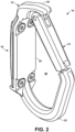
- the hook 22 can be somewhat squared off, as in FIG. 1 , rounded, as in FIG. 2 , or any other desired shape.
- the gap between the hook free end 26 and the finger 24 is an opening 34 into the interior 36 of the body 12 defined by the back 20, hook 22, and finger 24.
- the body has an attachment ring 40 for attaching items extending from the bottom 42 of the hook 22.
- the gate 14 has an elongated arm 50 with a pivot end 52 and a free end 54.
- a radial notch 56 formed by tines 58 in the pivot end 52 straddles the finger 24, as at 66.
- Lateral coaxial through holes 60 in the tines 58 are aligned with a through hole 62 in the finger 24.
- a pivot pin 64 extends through the holes 60, 62 and is secured. In the illustrated configuration, the pivot pin 64 is secured by being press fit into either the tine holes 60 or the finger hole 62. In the former case, the pin 64 pivots in the finger hole 62, and in the latter case, the tine holes 60 pivot on the pin 64.
- the pin 64 is the body of a rivet that is installed through the holes 60, 62, or the pin 64 is the body of a screw that extends through the holes 60, 62. Any mechanism that provides a pin 64 on which the gate 14 can pivot is contemplated by the present invention.
- the gate 14 pivots on the pivot pin 64 between a closed position 70, an inside position 72, and an outside position 74.
- the closed position 70 shown in FIG. 5
- the gate 14 spans the opening 34 between the finger 24 and the hook free end 26, preventing access to the interior 36.
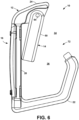
- the inside position 72 shown in FIG. 6
- the gate 14 is pivoted so that the arm free end 54 is within the interior 36, providing access to the interior 36.
- the outside position 74 shown in FIG. 7
- the gate 14 is pivoted so that the arm free end 54 is outside of the interior 36, providing access to the interior 36.
- an optional interlock 80 between the arm free end 54 and the hook free end 26 prevents side-to-side motion of the arm free end 54 relative to the hook free end 26.
- an interlock 80 There are a number of methods known in the art to form an interlock 80.
- a radial slot 82 in the arm free end 54 fits over a tab 84 extending from the hook free end 26 into the opening 34, as in FIG. 1 .
- the slot 82 extends in the direction that the gate 14 pivots so that the tab 84 slides through the slot 82 when the gate 14 pivots to the inside position 72 or the outside position 74.
- the device When a device, such as a carabiner, is being put on the tool holder 10, the device is typically pushed against the gate 14 so that the gate 14 opens to the inside position 72.
- the gate biasing mechanism 90 forces the gate 14 back to the closed position 70 as described above.
- the device When a device is then removed from the tool holder 10, the device is typically pulled against the gate 14 so that the gate 14 opens to the outside position 74.
- the gate biasing mechanism 90 forces the gate 14 back to the closed position 70 as described above.
- An optional gate lock 18, shown in FIGS. 8 and 11-21 prevents the gate 14 from opening when engaged and can be incorporated into the tool holder 10 when the interlock 80 is implemented.
- the configuration 106 of the gate lock 18 of FIGS. 8 and 11-18 includes a barrel 108 with an axial bore 110, a retainer end 116, a free end 112, and a radial slot 120 in the free end 112.
- the axial bore 110 fits over a narrow portion 116 of the arm 50 and is mounted to rotate about the narrow portion 116.
- the barrel 108 is positioned on the narrow portion 116 so that the retainer end 116 abuts a radial wall 118 formed by the change in diameter of the arm 50, and the barrel free end 112 is generally aligned with the arm free end 54, that is, the barrel free end 112 is within 5 mm of the arm free end 54.
- a pin 126 extends through an elongated, circumferential slot 128 in the barrel 108 and is secured in a hole 130 in the arm 50.
- the pin 126 can be secured by being press-fit into the hole 130, by threads turned into the hole 130, by adhesive, by magnet, or any other adequate means.
- the pin 126 has a head 136 for a tighter fit.
- the pin 126 provides two functions. The first is to secure the barrel 108 to the arm 50 so that the barrel 108 retained on the arm 50 but still be able to rotate about the arm 50. The second function is to provide rotational stops, as described below.
- the ring 202 surrounds the narrow portion 116 of the arm 50, straddling four flat surfaces 242, 244 that are 90° apart.
- the distance 246 between the short sides 214, 222 is no less than the diameter of the narrow portion 116.
- the distance 248 between the long sides 210, 218 is the same as the distance between opposed flat surfaces 242, 244 so that the long sides 201, 218 abut the flat surfaces 242, 244.
- the back outer surface 140 and/or plate surface 144/clip inner surface 190 are textured, as at 162 in FIG. 22 , to help retain the tool holder 10 in place on the webbing 2.
Landscapes
- Engineering & Computer Science (AREA)
- General Engineering & Computer Science (AREA)
- Mechanical Engineering (AREA)
- Hooks, Suction Cups, And Attachment By Adhesive Means (AREA)
Description
- The present invention relates to tool holders, more particularly, to hooks that mount to harnesses and belts to carry tools securely.
- Climbers who want the ability to carry climbing equipment, such as spare carabiners, lanyards, slings, and rope, use tool holders attached to their climbing harnesses and/or belts. The tool holder provides convenient access to working equipment. They can be designed to be attached to various locations on the harness/belt based on the user's preference. They are typically attached by specific hardware, such as screws with a matching receiving plate, to provide a secure attachment. A tool holder is known from XP093077584.
- The present invention is a tool holder according to claim 1, with a body, gate, and attachment. The body has a J shape with a hook and finger. The gap between the free end of the hook and the finger is an opening into the interior of the body. The body has an optional attachment ring.
- The gate has an arm. A radial notch formed by tines in a pivot end of the arm straddles the finger. A pivot pin extends through aligned holes in the tines and finger and secured. The gate pivots on the pivot pin between a closed position where the gate spans the opening, an inside position where the gate is pivoted into the interior, and an outside position where gate is pivoted outside of the body. An optional interlock between the free end of the arm and the hook free end prevents side-to-side motion of the arm when in the closed position. A gate biasing mechanism biases the gate to the closed position.
- When a device is being put on the tool holder, the device is pushed against the gate so that the gate opens to the inside position. When the device is in the interior, the gate biasing mechanism forces the gate back to the closed position. When a device is then removed from the tool holder, the device is pulled against the gate so that the gate opens to the outside position. When the device is outside of the interior, the gate biasing mechanism forces the gate back to the closed position.
- An optional gate lock prevents the gate from opening when engaged. In one configuration, the gate lock includes a barrel that fits over and rotates about the arm. A pin secures that barrel to the arm and operates as a rotational stop for the barrel as the barrel rotates between an unlocked position and a locked position. In the unlocked position, a lateral slot in the end of the barrel aligns with a lateral slot in the end of the arm, permitting a tab extending from the hook free end to pass through. The gate is free to pivot between the inside, outside, and closed positions. In the locked position, the barrel slot and arm slot are not aligned, capturing the tab, and preventing the gate from pivoting from the closed position. A retaining mechanism maintains the barrel in the unlocked or locked position until rotated manually.
- Another configuration of the gate lock includes a barrel with an axial bore that fits over a narrow portion of the arm so as to slide up and down the narrow portion. A pin secures the barrel to the arm.
- The barrel slides between an unlocked position, where the barrel bore does not extend over the hook tab and the gate is free to pivot between the closed, inside, and the outside position, and a locked position, where the barrel bore extends over the hook tab and the gate is retained in the closed position. A retaining mechanism retains the barrel in the unlocked or locked position until moved manually.
- The attachment secures the tool holder to the flat webbing of a harness, belt, or the like. In several configurations, the webbing is sandwiched between the flat surface on the back of the body and a flat surface on a plate that is secured to the body. Other configurations of the attachment include different clips. Optionally, textured surface(s) help retain the tool holder in place on the webbing.
- Objects of the present invention will become apparent in light of the following drawings and detailed description of the invention.
- For a fuller understanding of the nature and object of the present invention, reference is made to the accompanying drawings, wherein:
-
FIG. 1 is perspective view of the tool holder of the present invention; -
FIG. 2 is a perspective view of the tool holder with a rounded hook; -
FIG. 3 is a perspective view of the tool holder with a bottom loop; -
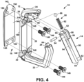
FIG. 4 is an exploded view of the tool holder; -
FIG. 5 is a side view of the tool holder in the closed position; -
FIG. 6 is a side view of the tool holder in the inner position; -
FIG. 7 is a side view of the tool holder in the outer position; -
FIG. 8 is a cross-sectional view of the gate biasing mechanism with the gate in the closed position and the gate lock in the locked position; -
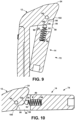
FIG. 9 is a cross-sectional view of the gate biasing mechanism with the gate in the interior position; -
FIG. 10 is a cross-sectional view of the gate biasing mechanism with the gate in the exterior position; -
FIG. 11 is perspective view of the tool holder with the optional gate lock in the locked position; -
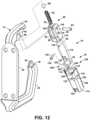
FIG. 12 is an exploded view of the tool holder with one configuration of the optional gate lock; -
FIG. 13 is a side view of the tool holder in the closed position with the optional gate lock ofFIG. 12 in the unlocked position; -
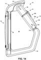
FIG. 14 is a side view of the tool holder in the closed position with the optional gate lock ofFIG. 12 in the locked position; -
FIG. 15 is a cross-sectional view at the friction ring retaining mechanism with gate lock in the unlocked position; -
FIG. 16 is a cross-sectional view at the friction ring retaining mechanism with gate lock in the locked position; -
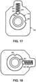
FIG. 17 is a cross-sectional view at the detent retaining mechanism with gate lock in the unlocked position; -
FIG. 18 is a cross-sectional view at the detent retaining mechanism with gate lock in the locked position; -
FIG. 19 is an exploded view of the tool holder with one configuration of the optional gate lock; -
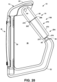
FIG. 20 is a side view of the tool holder in the closed position with the optional gate lock ofFIG. 19 in the unlocked position; -
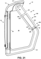
FIG. 21 is a side view of the tool holder in the closed position with the optional gate lock ofFIG. 19 in the locked position; -
FIG. 22 is an exploded view of one configuration of the tool holder attachment to a webbing; -
FIG. 23 is a perspective view of the tool holder attachment ofFIG. 22 assembled to a webbing; -
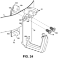
FIG. 24 is an exploded view of another configuration of the tool holder attachment to a webbing; -
FIG. 25 is a perspective view of the tool holder attachment ofFIG. 24 assembled to a webbing; -
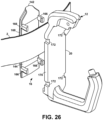
FIG. 26 is an exploded view of another configuration of the tool holder attachment to a webbing; -
FIG. 27 is a side, cross-sectional view of the tool holder attachment ofFIG. 26 assembled to a webbing; -
FIG. 28 is a side view of a clip configuration of the tool holder attachment to a webbing; and -
FIG. 29 is a side view of another clip configuration of the tool holder attachment to a webbing. - The present invention is a
tool holder 10 with abody 12, agate 14, and anattachment 16. Thebody 12 has a J shape with avertical back 20, afinger 24 extending generally perpendicularly from theupper end 28 of the back 20, and ahook 22 with afree end 26 extending from thelower end 30 of the back 20 from the same side as thefinger 24. Thehook 22 can be somewhat squared off, as inFIG. 1 , rounded, as inFIG. 2 , or any other desired shape. - The gap between the hook
free end 26 and thefinger 24 is anopening 34 into the interior 36 of thebody 12 defined by the back 20,hook 22, andfinger 24. - Optionally, as shown in
FIG. 3 , the body has anattachment ring 40 for attaching items extending from the bottom 42 of thehook 22. - The
gate 14 has anelongated arm 50 with apivot end 52 and afree end 54. Aradial notch 56 formed bytines 58 in thepivot end 52 straddles thefinger 24, as at 66. Lateral coaxial throughholes 60 in thetines 58 are aligned with a throughhole 62 in thefinger 24. Apivot pin 64 extends through theholes pivot pin 64 is secured by being press fit into either the tine holes 60 or thefinger hole 62. In the former case, thepin 64 pivots in thefinger hole 62, and in the latter case, the tine holes 60 pivot on thepin 64. Alternatively, thepin 64 is the body of a rivet that is installed through theholes pin 64 is the body of a screw that extends through theholes pin 64 on which thegate 14 can pivot is contemplated by the present invention. - The
gate 14 pivots on thepivot pin 64 between aclosed position 70, aninside position 72, and anoutside position 74. In theclosed position 70, shown inFIG. 5 , thegate 14 spans theopening 34 between thefinger 24 and the hookfree end 26, preventing access to the interior 36. In theinside position 72, shown inFIG. 6 , thegate 14 is pivoted so that the armfree end 54 is within the interior 36, providing access to the interior 36. In theoutside position 74, shown inFIG. 7 , thegate 14 is pivoted so that the armfree end 54 is outside of the interior 36, providing access to the interior 36. - When the
gate 14 is in theclosed position 70, anoptional interlock 80 between the armfree end 54 and the hookfree end 26 prevents side-to-side motion of the armfree end 54 relative to the hookfree end 26. There are a number of methods known in the art to form aninterlock 80. In the present design, aradial slot 82 in the armfree end 54 fits over atab 84 extending from the hookfree end 26 into theopening 34, as inFIG. 1 . Theslot 82 extends in the direction that thegate 14 pivots so that thetab 84 slides through theslot 82 when thegate 14 pivots to theinside position 72 or theoutside position 74. - A
gate biasing mechanism 90 biases thegate 14 to theclosed position 70. In the present design, shown inFIGS. 8-10 , acoil spring 92 fits in aclosed bore 94 in thearm 50. Asteel ball 96 rests on the end of thespring 92 and thespring 92 pushes theball 96 into afinger notch 98 in thefinger 24. When thegate 14 is pushed opened to theinside position 72, thesteel ball 96 rolls out of thefinger notch 98 to theinside surface 100 of thefinger 24, thereby compressing thespring 92. When the pushing force is removed, thespring 92 pushes theball 96 back into thefinger notch 98, whereby thegate 14 returns to theclosed position 70. When thegate 14 is opened to theoutside position 74, thesteel ball 96 rolls out of thefinger notch 98 to theoutside surface 102 of thefinger 24, thereby compressing thespring 92. When the pushing force is removed, thespring 92 pushes theball 96 back into thefinger notch 98, whereby thegate 14 returns to theclosed position 70. Optionalrounded grooves 104 in thetines 58 keep thespring 92 andball 96 in place. - When a device, such as a carabiner, is being put on the
tool holder 10, the device is typically pushed against thegate 14 so that thegate 14 opens to theinside position 72. When the device is in the interior 36 and hung on thehook 22, thegate biasing mechanism 90 forces thegate 14 back to theclosed position 70 as described above. - When a device is then removed from the
tool holder 10, the device is typically pulled against thegate 14 so that thegate 14 opens to theoutside position 74. When the device is outside of the interior 36, thegate biasing mechanism 90 forces thegate 14 back to theclosed position 70 as described above. - An
optional gate lock 18, shown inFIGS. 8 and11-21 , prevents thegate 14 from opening when engaged and can be incorporated into thetool holder 10 when theinterlock 80 is implemented. Theconfiguration 106 of thegate lock 18 ofFIGS. 8 and11-18 includes abarrel 108 with anaxial bore 110, aretainer end 116, afree end 112, and aradial slot 120 in thefree end 112. Theaxial bore 110 fits over anarrow portion 116 of thearm 50 and is mounted to rotate about thenarrow portion 116. Thebarrel 108 is positioned on thenarrow portion 116 so that theretainer end 116 abuts aradial wall 118 formed by the change in diameter of thearm 50, and the barrelfree end 112 is generally aligned with the armfree end 54, that is, the barrelfree end 112 is within 5 mm of the armfree end 54. - A
pin 126 extends through an elongated,circumferential slot 128 in thebarrel 108 and is secured in ahole 130 in thearm 50. Thepin 126 can be secured by being press-fit into thehole 130, by threads turned into thehole 130, by adhesive, by magnet, or any other adequate means. Optionally, thepin 126 has ahead 136 for a tighter fit. - The
pin 126 provides two functions. The first is to secure thebarrel 108 to thearm 50 so that thebarrel 108 retained on thearm 50 but still be able to rotate about thearm 50. The second function is to provide rotational stops, as described below. - The
barrel 108 rotates between anunlocked position 122 and a lockedposition 124. In theunlocked position 122, thepin 126 is against anunlock stop 132 at one end of theslot 128 and thebarrel slot 120 is aligned with thearm slot 82. In the lockedposition 124, thepin 126 is against alock stop 134 at the other end of theslot 128 and thebarrel slot 120 is not aligned with thearm slot 82. Typically, the length of theslot 128, and hence to location of theunlock stop 132 and lock stop 134, is such that theunlocked position 122 and the lockedposition 124 are about 90° of rotation apart. This means that theslot 128 extends about 90° around the wall of thebarrel 108. When in theunlocked position 122, thebarrel slot 120 is aligned with thearm slot 82 so that thebarrel 108 does not block thearm slot 82, permitting thehook tab 84 to pass through thearm slot 82 in either direction. When in the lockedposition 124, thebarrel 108 blocks thearm slot 82 so that thetab 84 cannot pass through in either direction, thereby preventing thegate 14 from opening. - In order to retain the
barrel 108 in the unlocked or locked position until rotated manually, the present invention employs aretaining mechanism 200. One such retaining mechanism is shown inFIGS. 15 and 16 . Aring 202 sits in alateral depression 204 at the retaining end 206 of thebarrel 108. Thering 202 is a length of spring steel formed into a planar rectangle with an openlong side 210, a first 90°bend 212, a closedshort side 214, a second 90°bend 216, a closedlong side 218, a third 90°bend 220, and an openshort side 222. The lengths of the long sides and short sides are discussed below. The openlong side 212 has afree end 224 with ashort finger 228 bent at a 90° angle orthogonal to the plane of thering 202. The openshort side 222 has afree end 226. There is agap 230 between the open long sidefree end 224 and the open short sidefree end 226. - The
depression 204 is rectangular and thering 202 sits in thedepression 204 such that theshort sides sides 234 of thedepression 204. Thefinger 228 extends into ahole 236 in thefloor 236 of thedepression 204 in order to maintain the position of thering 202 in the depression. Thering 204 is retained in thedepression 204 by theretainer end 116 of thebarrel 108 abutting thearm wall 118 so that thearm wall 118 covers thedepression 204. - The
ring 202 surrounds thenarrow portion 116 of thearm 50, straddling fourflat surfaces distance 246 between theshort sides narrow portion 116. Thedistance 248 between thelong sides flat surfaces long sides 201, 218 abut theflat surfaces gate lock 106 is in theunlocked position 122, thelong sides flat surfaces 242, as inFIG. 15 . When thebarrel 108 is rotated clockwise inFIG. 15 toward the lockedposition 124 ofFIG. 16 , the round perimeter surfaces 250 between theflat surfaces long sides ring 202. As thebarrel 108 continues to rotate, thelong sides flat surfaces 244, permitting thering 204 to snap back to its normal shape, with thelong sides flat surfaces 244. To unlock thegate lock 106, thebarrel 108 is rotated counterclockwise. - A detent retaining mechanism is shown in
FIGS. 17 and 18 . Thenarrow portion 116 of thearm 50 has two rounded depressions, anunlock depression 256 and alock depression 258 that are 90° apart. Acoil spring 260 andsteel ball 262 reside in aradial bore 264 in thebarrel 108, where thespring 260 pushes theball 262 against thearm 50. When thebarrel 108 is in thelock position 122, as inFIG. 17 , theball 262 is aligned with theunlock depression 256 and thespring 260 pushes theball 262 into theunlock depression 256, retaining thebarrel 108 in theunlock position 122. To rotate thebarrel 108 to thelock position 124, enough force must be applied to rotate thebarrel 108 to overcome thespring 260 and move theball 262 from theunlock depression 256. When thebarrel 108 is rotated to thelock position 124, as inFIG. 18 , theball 262 is aligned with thelock depression 258 and thespring 260 pushes theball 262 into thelock depression 258, retaining thebarrel 108 in thelock position 124. - The present invention contemplates the use of any other adequate retaining mechanisms.
- The
gate lock configuration 270 ofFIGS. 19-21 includes abarrel 272 with anaxial bore 274, abutt end 278, and afree end 276. Theaxial bore 274 fits over anarrow portion 280 of thearm 50 and is mounted to slide up and down thenarrow portion 280. - A
pin 288 secures thebarrel 272 to thearm 50 by extending through an elongated,longitudinal slot 290 in thebarrel 272 and being secured in ahole 292 in thearm 50. Thepin 288 can be secured by being press-fit into thehole 292, by threads turned into thehole 292, by adhesive, by magnet, or any other adequate means. Optionally, thepin 288 has ahead 294 for a tighter fit. - The
barrel 272 slides between anunlocked position 284, where the barrel bore 274 does not extend over thehook tab 84 and thegate 14 is free to pivot between theclosed position 70, theinside position 72, and theoutside position 74, as inFIG. 20 , and a lockedposition 286, where the barrel bore 274 extends over thehook tab 84 and thegate 14 is retained in theclosed position 70, as inFIG. 21 . - An
unlock stop 296 is provided by thebarrel butt end 278 abutting theshoulder 282 on thearm 50 at thenarrow portion 280. Alock stop 298 is provided by the barrelfree end 276 abutting the hookfree end 26. Theslot 290 is long enough so that both stops 296, 298 can be reached by thebarrel 272. - In order to retain the
barrel 272 in the unlocked or locked position until slid manually, the present invention employs a retaining mechanism. The present invention contemplates the use of any adequate retaining mechanisms, including friction rings and detents. - The
attachment 16 secures thetool holder 10 to theflat webbing 2 of a harness, belt, or the like. The present invention contemplates any mechanism the adequately secures thetool holder 10. - In the illustrated configurations of
FIGS. 22-27 , the back 20 has a flatouter surface 140. Aplate 142 with a flatinner surface 144 removably attaches to the backouter surface 140. - In the configuration of
FIGS. 22 and23 , theplate 142 is attached by removable fasteners, screws 146 in the present illustration, that extend throughholes 148 in the four corners of the back 20 and turn into corresponding threadedholes 150 in theplate 142 to secure theplate 142 to the back 20. Alternatively, thescrews 146 extend through holes in the four corners of theplate 142 and turn into corresponding threaded holes in the back 20 to secure theplate 142 to the back 20. Alternatively, there are no screws or holes and theplate 142 is attached to the back 20 by magnets. - In the configuration of
FIGS. 24 and25 , theplate 142 is attached at one end by a detachable hinge 154, with a lateral,elongated slot 156 in the backouter surface 140 and a lateral,elongated hook 158 at the lower end 160 of theplate 142. Thehook 158 hooks into theslot 156. Removable fasteners, screws 146 in the present illustration, extend throughholes 148 in the upper corners of the back 20 and turn into corresponding threadedholes 150 in theplate 142 to secure theplate 142 to the back 20. Alternatively, thescrews 146 extend through holes in the upper corners of theplate 142 and turn into corresponding threaded holes in the back 20 to secure theplate 142 to the back 20. Alternatively, the attachment is reversed with thehook 158 at the upper end of the plate. - In the configuration of
FIGS. 26 and27 , theplate 142 is attached bysprings clips 166 at each corner of theplate 142. Theclips 166 extend perpendicularly and vertically from the upper andlower sides 168 of theplate 142, and snap onto the side edges 170 of the backouter surface 140. Alternatively, theclips 166 extend perpendicularly and horizontally from the upper and lower edges of theplate 142, and snap onto the upper and lower edges, respectively, of the backouter surface 140. Alternatively, theclips 166 extend from the backouter surface 140 and snap onto the edges of theplate 142. Optionally, theclips 166 snap intonotches 172. - When the
plate 142 is attached to the back 20, thewebbing 2 is sandwiched between the backouter surface 140 and the plateinner surface 144 in agap 152, as inFIGS. 23 ,25 , and27 . Optionally, the backouter surface 140 and/or the plateinner surface 144 are textured, as at 174, to help keep thetool holder 10 from sliding around on thewebbing 2. - In the illustrated configurations of
FIGS. 28 and29 , aclip 178 extends from the back 20. Theclip 178 extends downwardly from theupper portion 180 of the back 20 and forms agap 182 between theclip 178 and the backouter surface 140. Theupper end 184 of thegap 182 is closed and thelower end 186 of thegap 182 is open. In the configuration ofFIG. 28 , theclip 178 is biased toward the back 20 and therefore squeezes thewebbing 2 against the backouter surface 140 to hold thetool holder 10 on thewebbing 2. In the configuration ofFIG. 29 , theclip 178 further hooks around thebottom edge 6 of thewebbing 2, as at 188. The closedupper end 184 of thegap 182 and thehook 188 capture thewebbing 2 to hold thetool holder 10 in place. - Optionally, the back
outer surface 140 and/orplate surface 144/clipinner surface 190 are textured, as at 162 inFIG. 22 , to help retain thetool holder 10 in place on thewebbing 2. - Thus, it has been shown and described a tool holder. Since certain changes may be made in the present disclosure without departing from the scope of the present invention as determined by the appended claims, it is intended that all matter described in the foregoing specification and shown in the accompanying drawings be interpreted as illustrative and not in a limiting sense.
Claims (12)
- A tool holder (10) comprising:(a) a body (12) with a back (20) having a flat outer surface (140), a back upper end (28), a back lower end (30), a finger (24) extending from the back upper end (28), and a hook (22) extending from the back lower end (30), the hook (22) having a free end (26) extending generally toward the finger (24);(b) an opening (34) spanning the finger (24) and the hook free end (26), the opening (34) providing access to an interior (36) defined by the back (20), hook (22), and finger (24);(c) a gate (14) with an elongated arm (50) having a pivot end (52) and a free end (54), the arm pivot end (52) pivotally attached at the finger (24) to pivot between a closed position (70) wherein the gate (14) spans the opening (34), an inside position (72) wherein the arm free end (54) is within the interior (36), and an outside position (74) wherein the arm free end (54) is outside of the interior (36) and opening (34), the gate (14) being biased to the closed position (70); and(d) an attachment mechanism (16) adapted for attaching the back (20) to a webbing (02).
- The tool holder (10) of claim 1 further comprising a gate lock (18) having an unlocked position (122) wherein the gate (14) is permitted to move between the inside position (72), closed position (70), and outside position (74), and a locked position (124) wherein the gate (14) is prevented from moving from the closed position (70).
- The tool holder (10) of claim 1 or 2 wherein the gate (14) is biased to the closed position (70) by a biasing mechanism (90) comprising a coil spring (92) in an axial bore (94) in the pivot end (52) of the gate arm (50) and a steel ball (96) between the coil spring (92) and a finger notch (98) in the finger (24), whereby, when pressure is applied to move the gate (14) to the inside position (72) or outside position (74), the steel ball (96) moves away from the finger notch (98), compressing the spring (92), and when the pressure is removed, the spring (92) pushes the steel ball (96) back to the finger notch (98) and the gate (14) to the closed position (70).
- The tool holder (10) of any preceding claim wherein the arm free end (54) and the hook free end (26) interlock (80) when the gate (14) is in the closed position (70).
- The tool holder (10) of claim 4 wherein the interlock (80) is comprised of a tab (84) extending from the hook free end (26) and a radial arm notch (82) in the arm free end (54), whereby the tab (84) resides in the arm notch (82) when the gate (14) is in the closed position (70) and the tab (84) slides out of the arm notch (82) when the gate (14) moves to the inside position (72) or the outside position (74).
- The tool holder (10) of claim 5 further comprising a gate lock (18) comprised of a barrel (108) mounted to rotate about the arm (50), the barrel (108) having a barrel free end (112) generally aligned with the arm free end (54) and having a radial barrel notch, the barrel (108) rotating between an unlocked position wherein the barrel notch (120) is aligned with the arm notch (82), and a locked position (124) wherein the barrel notch (120) is not aligned with the arm notch (82).
- The tool holder (10) of claim 6 further comprising a pin (126) extending through an elongated circumferential slot (128) in the barrel (108) and secured into a hole (130) in the arm (50), the pin (126) retaining the barrel (108) on the arm (50) and providing rotational stops (132, 134) for the unlocked position (122) and the locked position (124).
- The tool holder (10) of claim 6 or 7 further comprising a retaining mechanism (200) for retaining the barrel (108) in the unlocked position (122) and the locked position (124).
- The tool holder (10) of any preceding claim further comprising an attachment ring (40) on the hook (22).
- The tool holder (10) of any preceding claim wherein the attachment mechanism (16) comprises a plate (142) with a flat inner surface (144) removably mounted to the outer surface (140) of the back (20) whereby the webbing (02) can be sandwiched between the outer surface (140) of the back (20) and the inner surface (144) of the plate (142).
- The tool holder (10) of claim 10 wherein one or both of the outer surface (140) and the inner surface (144) are textured (174).
- The tool holder (10) of claim 10 or 11 wherein the plate (142) is removably attached to the back (20) by screws (146).
Applications Claiming Priority (1)
| Application Number | Priority Date | Filing Date | Title |
|---|---|---|---|
| US17/725,738 US11470951B1 (en) | 2022-04-21 | 2022-04-21 | Tool holder |
Publications (3)
| Publication Number | Publication Date |
|---|---|
| EP4265927A1 EP4265927A1 (en) | 2023-10-25 |
| EP4265927B1 true EP4265927B1 (en) | 2025-06-04 |
| EP4265927C0 EP4265927C0 (en) | 2025-06-04 |
Family
ID=83603461
Family Applications (1)
| Application Number | Title | Priority Date | Filing Date |
|---|---|---|---|
| EP23168516.5A Active EP4265927B1 (en) | 2022-04-21 | 2023-04-18 | Tool holder |
Country Status (3)
| Country | Link |
|---|---|
| US (1) | US11470951B1 (en) |
| EP (1) | EP4265927B1 (en) |
| JP (1) | JP2023160783A (en) |
Families Citing this family (4)
| Publication number | Priority date | Publication date | Assignee | Title |
|---|---|---|---|---|
| USD1039938S1 (en) * | 2022-04-08 | 2024-08-27 | Trayvax Enterprises Llc | Keychain multitool |
| US12551002B2 (en) * | 2022-09-02 | 2026-02-17 | Blue Force Gear, Inc. | Accessory adapter |
| US11814175B1 (en) * | 2022-11-22 | 2023-11-14 | Autoflight (Kunshan) Co., Ltd. | Unmanned aerial vehicle (UAV) delivery structure |
| USD1023717S1 (en) * | 2023-06-10 | 2024-04-23 | Weihong GUAN | Multi-tool knife |
Family Cites Families (18)
| Publication number | Priority date | Publication date | Assignee | Title |
|---|---|---|---|---|
| DE2614961C3 (en) * | 1976-04-07 | 1979-02-01 | Brueggemann & Brand Kg, 5802 Wetter | Snap hook, especially for transporting heavy external loads on helicopters |
| US6729517B2 (en) * | 2000-12-04 | 2004-05-04 | Ralph Ernest Grover | Clamping apparatus |
| US6588076B1 (en) * | 2002-04-08 | 2003-07-08 | Gary E. Choate | Carabiner with locking gate |
| US6715898B1 (en) * | 2002-10-31 | 2004-04-06 | Sky Wave Industrial Co. Ltd. | Carabiner |
| TWM271062U (en) * | 2004-12-21 | 2005-07-21 | Sinox Co Ltd | Padlock |
| US7946006B2 (en) | 2006-07-10 | 2011-05-24 | Techxotic, L.C. | Carabiner having dual gates and associated methods |
| US20100325848A1 (en) * | 2009-06-24 | 2010-12-30 | Feng Chia Liang | Snap hook with rotatable lock |
| US8480690B2 (en) * | 2009-12-17 | 2013-07-09 | Raghavendra Rao Vijayanagar | Suture organizer |
| AU2010241470A1 (en) * | 2010-11-16 | 2012-05-31 | N'vision Creative Concepts Pty Ltd | A Locking Attachment Device |
| WO2013113943A1 (en) | 2012-02-03 | 2013-08-08 | Grivel S.R.L. | Safety carabiner comprising a double gate |
| DE202013104652U1 (en) * | 2013-10-15 | 2013-10-30 | Bahsys Gmbh & Co. Kg | carabiner |
| US20160153487A1 (en) * | 2014-11-28 | 2016-06-02 | Steven J. Hollinger | Fastener with improved gate |
| US9638237B2 (en) * | 2015-06-11 | 2017-05-02 | Neng-Yuan Yeh | Snap hook apparatus |
| JP3213129U (en) * | 2017-08-09 | 2017-10-19 | 井本刃物株式会社 | Carabiner fixed band |
| US10793077B2 (en) | 2017-11-30 | 2020-10-06 | Ford Global Technologies, Llc | Carabiner-style cargo hook |
| US10948006B2 (en) | 2018-10-19 | 2021-03-16 | Outdoor Element, Llc | Carabiner with container gate |
| GB2581804B (en) | 2019-02-26 | 2021-12-08 | Treemagineers Ltd | Device for carrying articles of equipment |
| US12085115B2 (en) * | 2020-06-05 | 2024-09-10 | Derek Peterson | Locking carabiner |
-
2022
- 2022-04-21 US US17/725,738 patent/US11470951B1/en active Active
-
2023
- 2023-04-18 EP EP23168516.5A patent/EP4265927B1/en active Active
- 2023-04-19 JP JP2023068385A patent/JP2023160783A/en active Pending
Also Published As
| Publication number | Publication date |
|---|---|
| JP2023160783A (en) | 2023-11-02 |
| US11470951B1 (en) | 2022-10-18 |
| EP4265927C0 (en) | 2025-06-04 |
| EP4265927A1 (en) | 2023-10-25 |
Similar Documents
| Publication | Publication Date | Title |
|---|---|---|
| EP4265927A1 (en) | Tool holder | |
| US8979397B2 (en) | Camera body with integral strap connector | |
| US5201858A (en) | Quick-release connector | |
| US12607298B1 (en) | Accessory mount for environmental surface | |
| EP3681349B1 (en) | Furniture securing device | |
| US8727294B1 (en) | Handgun holding system | |
| JP6564467B2 (en) | Container mounting assembly | |
| US11672325B2 (en) | Tool attachment system | |
| US8443495B2 (en) | Carabiner with anti-cross loading feature | |
| US20130168429A1 (en) | Belt-mounted, Two-way Radio Holder Unit Assembly | |
| US10730718B2 (en) | Ambidextural retracting reel and device securable to an article | |
| US20110315840A1 (en) | Universal cam lock mount | |
| US11407610B2 (en) | Equipment tether | |
| US20220349439A1 (en) | Device for carrying articles of equipment | |
| EP4060279A1 (en) | Bipod with sling stud mount | |
| EP2418343A2 (en) | Opening restrictor | |
| CN116464357B (en) | Rebounder | |
| US10436551B1 (en) | Holster mounting system | |
| WO2022205809A1 (en) | Strap buckle | |
| WO2025019930A1 (en) | Apparatus for ascending and descending a line with a load | |
| US20020085344A1 (en) | Personal data assistant carrying apparatus | |
| US20240183643A1 (en) | Magazine carrier | |
| US12297678B1 (en) | Device to slow or stop a door from opening | |
| EP4643716A1 (en) | A hanger accessory and hanger system | |
| JP2020122344A (en) | One-touch mounting handle |
Legal Events
| Date | Code | Title | Description |
|---|---|---|---|
| STAA | Information on the status of an ep patent application or granted ep patent |
Free format text: STATUS: THE APPLICATION HAS BEEN PUBLISHED |
|
| PUAI | Public reference made under article 153(3) epc to a published international application that has entered the european phase |
Free format text: ORIGINAL CODE: 0009012 |
|
| AK | Designated contracting states |
Kind code of ref document: A1 Designated state(s): AL AT BE BG CH CY CZ DE DK EE ES FI FR GB GR HR HU IE IS IT LI LT LU LV MC ME MK MT NL NO PL PT RO RS SE SI SK SM TR |
|
| STAA | Information on the status of an ep patent application or granted ep patent |
Free format text: STATUS: REQUEST FOR EXAMINATION WAS MADE |
|
| 17P | Request for examination filed |
Effective date: 20240330 |
|
| RBV | Designated contracting states (corrected) |
Designated state(s): AL AT BE BG CH CY CZ DE DK EE ES FI FR GB GR HR HU IE IS IT LI LT LU LV MC ME MK MT NL NO PL PT RO RS SE SI SK SM TR |
|
| GRAP | Despatch of communication of intention to grant a patent |
Free format text: ORIGINAL CODE: EPIDOSNIGR1 |
|
| STAA | Information on the status of an ep patent application or granted ep patent |
Free format text: STATUS: GRANT OF PATENT IS INTENDED |
|
| RIC1 | Information provided on ipc code assigned before grant |
Ipc: A45F 5/02 20060101ALI20250130BHEP Ipc: F16B 45/02 20060101AFI20250130BHEP |
|
| INTG | Intention to grant announced |
Effective date: 20250207 |
|
| GRAS | Grant fee paid |
Free format text: ORIGINAL CODE: EPIDOSNIGR3 |
|
| GRAA | (expected) grant |
Free format text: ORIGINAL CODE: 0009210 |
|
| STAA | Information on the status of an ep patent application or granted ep patent |
Free format text: STATUS: THE PATENT HAS BEEN GRANTED |
|
| AK | Designated contracting states |
Kind code of ref document: B1 Designated state(s): AL AT BE BG CH CY CZ DE DK EE ES FI FR GB GR HR HU IE IS IT LI LT LU LV MC ME MK MT NL NO PL PT RO RS SE SI SK SM TR |
|
| REG | Reference to a national code |
Ref country code: GB Ref legal event code: FG4D |
|
| REG | Reference to a national code |
Ref country code: CH Ref legal event code: EP |
|
| REG | Reference to a national code |
Ref country code: IE Ref legal event code: FG4D |
|
| U01 | Request for unitary effect filed |
Effective date: 20250604 |
|
| U07 | Unitary effect registered |
Designated state(s): AT BE BG DE DK EE FI FR IT LT LU LV MT NL PT RO SE SI Effective date: 20250611 |
|
| PG25 | Lapsed in a contracting state [announced via postgrant information from national office to epo] |
Ref country code: ES Free format text: LAPSE BECAUSE OF FAILURE TO SUBMIT A TRANSLATION OF THE DESCRIPTION OR TO PAY THE FEE WITHIN THE PRESCRIBED TIME-LIMIT Effective date: 20250604 |
|
| PG25 | Lapsed in a contracting state [announced via postgrant information from national office to epo] |
Ref country code: NO Free format text: LAPSE BECAUSE OF FAILURE TO SUBMIT A TRANSLATION OF THE DESCRIPTION OR TO PAY THE FEE WITHIN THE PRESCRIBED TIME-LIMIT Effective date: 20250904 Ref country code: GR Free format text: LAPSE BECAUSE OF FAILURE TO SUBMIT A TRANSLATION OF THE DESCRIPTION OR TO PAY THE FEE WITHIN THE PRESCRIBED TIME-LIMIT Effective date: 20250905 |
|
| PG25 | Lapsed in a contracting state [announced via postgrant information from national office to epo] |
Ref country code: PL Free format text: LAPSE BECAUSE OF FAILURE TO SUBMIT A TRANSLATION OF THE DESCRIPTION OR TO PAY THE FEE WITHIN THE PRESCRIBED TIME-LIMIT Effective date: 20250604 |
|
| PG25 | Lapsed in a contracting state [announced via postgrant information from national office to epo] |
Ref country code: HR Free format text: LAPSE BECAUSE OF FAILURE TO SUBMIT A TRANSLATION OF THE DESCRIPTION OR TO PAY THE FEE WITHIN THE PRESCRIBED TIME-LIMIT Effective date: 20250604 |
|
| PG25 | Lapsed in a contracting state [announced via postgrant information from national office to epo] |
Ref country code: RS Free format text: LAPSE BECAUSE OF FAILURE TO SUBMIT A TRANSLATION OF THE DESCRIPTION OR TO PAY THE FEE WITHIN THE PRESCRIBED TIME-LIMIT Effective date: 20250904 |
|
| PG25 | Lapsed in a contracting state [announced via postgrant information from national office to epo] |
Ref country code: IS Free format text: LAPSE BECAUSE OF FAILURE TO SUBMIT A TRANSLATION OF THE DESCRIPTION OR TO PAY THE FEE WITHIN THE PRESCRIBED TIME-LIMIT Effective date: 20251004 |
|
| PG25 | Lapsed in a contracting state [announced via postgrant information from national office to epo] |
Ref country code: SM Free format text: LAPSE BECAUSE OF FAILURE TO SUBMIT A TRANSLATION OF THE DESCRIPTION OR TO PAY THE FEE WITHIN THE PRESCRIBED TIME-LIMIT Effective date: 20250604 |
|
| PG25 | Lapsed in a contracting state [announced via postgrant information from national office to epo] |
Ref country code: CZ Free format text: LAPSE BECAUSE OF FAILURE TO SUBMIT A TRANSLATION OF THE DESCRIPTION OR TO PAY THE FEE WITHIN THE PRESCRIBED TIME-LIMIT Effective date: 20250604 |
|
| PG25 | Lapsed in a contracting state [announced via postgrant information from national office to epo] |
Ref country code: SK Free format text: LAPSE BECAUSE OF FAILURE TO SUBMIT A TRANSLATION OF THE DESCRIPTION OR TO PAY THE FEE WITHIN THE PRESCRIBED TIME-LIMIT Effective date: 20250604 |
|
| PLBE | No opposition filed within time limit |
Free format text: ORIGINAL CODE: 0009261 |
|
| STAA | Information on the status of an ep patent application or granted ep patent |
Free format text: STATUS: NO OPPOSITION FILED WITHIN TIME LIMIT |
|
| REG | Reference to a national code |
Ref country code: CH Ref legal event code: L10 Free format text: ST27 STATUS EVENT CODE: U-0-0-L10-L00 (AS PROVIDED BY THE NATIONAL OFFICE) Effective date: 20260416 |
|
| 26N | No opposition filed |
Effective date: 20260305 |