EP4265920A1 - Integrated pump device - Google Patents
Integrated pump device Download PDFInfo
- Publication number
- EP4265920A1 EP4265920A1 EP21906038.1A EP21906038A EP4265920A1 EP 4265920 A1 EP4265920 A1 EP 4265920A1 EP 21906038 A EP21906038 A EP 21906038A EP 4265920 A1 EP4265920 A1 EP 4265920A1
- Authority
- EP
- European Patent Office
- Prior art keywords
- oil
- oil pump
- chamber
- vane
- reverse
- Prior art date
- Legal status (The legal status is an assumption and is not a legal conclusion. Google has not performed a legal analysis and makes no representation as to the accuracy of the status listed.)
- Granted
Links
Images








Classifications
-
- B—PERFORMING OPERATIONS; TRANSPORTING
- B60—VEHICLES IN GENERAL
- B60T—VEHICLE BRAKE CONTROL SYSTEMS OR PARTS THEREOF; BRAKE CONTROL SYSTEMS OR PARTS THEREOF, IN GENERAL; ARRANGEMENT OF BRAKING ELEMENTS ON VEHICLES IN GENERAL; PORTABLE DEVICES FOR PREVENTING UNWANTED MOVEMENT OF VEHICLES; VEHICLE MODIFICATIONS TO FACILITATE COOLING OF BRAKES
- B60T1/00—Arrangements of braking elements, i.e. of those parts where braking effect occurs specially for vehicles
- B60T1/005—Arrangements of braking elements, i.e. of those parts where braking effect occurs specially for vehicles by locking of wheel or transmission rotation
-
- F—MECHANICAL ENGINEERING; LIGHTING; HEATING; WEAPONS; BLASTING
- F15—FLUID-PRESSURE ACTUATORS; HYDRAULICS OR PNEUMATICS IN GENERAL
- F15B—SYSTEMS ACTING BY MEANS OF FLUIDS IN GENERAL; FLUID-PRESSURE ACTUATORS, e.g. SERVOMOTORS; DETAILS OF FLUID-PRESSURE SYSTEMS, NOT OTHERWISE PROVIDED FOR
- F15B15/00—Fluid-actuated devices for displacing a member from one position to another; Gearing associated therewith
- F15B15/18—Combined units comprising both motor and pump
-
- F—MECHANICAL ENGINEERING; LIGHTING; HEATING; WEAPONS; BLASTING
- F16—ENGINEERING ELEMENTS AND UNITS; GENERAL MEASURES FOR PRODUCING AND MAINTAINING EFFECTIVE FUNCTIONING OF MACHINES OR INSTALLATIONS; THERMAL INSULATION IN GENERAL
- F16H—GEARING
- F16H63/00—Control outputs from the control unit to change-speed- or reversing-gearings for conveying rotary motion or to other devices than the final output mechanism
- F16H63/02—Final output mechanisms therefor; Actuating means for the final output mechanisms
- F16H63/30—Constructional features of the final output mechanisms
- F16H63/34—Locking or disabling mechanisms
- F16H63/3416—Parking lock mechanisms or brakes in the transmission
- F16H63/3483—Parking lock mechanisms or brakes in the transmission with hydraulic actuating means
-
- B—PERFORMING OPERATIONS; TRANSPORTING
- B60—VEHICLES IN GENERAL
- B60T—VEHICLE BRAKE CONTROL SYSTEMS OR PARTS THEREOF; BRAKE CONTROL SYSTEMS OR PARTS THEREOF, IN GENERAL; ARRANGEMENT OF BRAKING ELEMENTS ON VEHICLES IN GENERAL; PORTABLE DEVICES FOR PREVENTING UNWANTED MOVEMENT OF VEHICLES; VEHICLE MODIFICATIONS TO FACILITATE COOLING OF BRAKES
- B60T17/00—Component parts, details, or accessories of power brake systems not covered by groups B60T8/00, B60T13/00 or B60T15/00, or presenting other characteristic features
-
- F—MECHANICAL ENGINEERING; LIGHTING; HEATING; WEAPONS; BLASTING
- F04—POSITIVE - DISPLACEMENT MACHINES FOR LIQUIDS; PUMPS FOR LIQUIDS OR ELASTIC FLUIDS
- F04C—ROTARY-PISTON, OR OSCILLATING-PISTON, POSITIVE-DISPLACEMENT MACHINES FOR LIQUIDS; ROTARY-PISTON, OR OSCILLATING-PISTON, POSITIVE-DISPLACEMENT PUMPS
- F04C13/00—Adaptations of machines or pumps for special use, e.g. for extremely high pressures
- F04C13/001—Pumps for particular liquids
- F04C13/002—Pumps for particular liquids for homogeneous viscous liquids
-
- F—MECHANICAL ENGINEERING; LIGHTING; HEATING; WEAPONS; BLASTING
- F04—POSITIVE - DISPLACEMENT MACHINES FOR LIQUIDS; PUMPS FOR LIQUIDS OR ELASTIC FLUIDS
- F04C—ROTARY-PISTON, OR OSCILLATING-PISTON, POSITIVE-DISPLACEMENT MACHINES FOR LIQUIDS; ROTARY-PISTON, OR OSCILLATING-PISTON, POSITIVE-DISPLACEMENT PUMPS
- F04C15/00—Component parts, details or accessories of machines, pumps or pumping installations, not provided for in groups F04C2/00 - F04C14/00
- F04C15/06—Arrangements for admission or discharge of the working fluid, e.g. constructional features of the inlet or outlet
-
- F—MECHANICAL ENGINEERING; LIGHTING; HEATING; WEAPONS; BLASTING
- F15—FLUID-PRESSURE ACTUATORS; HYDRAULICS OR PNEUMATICS IN GENERAL
- F15B—SYSTEMS ACTING BY MEANS OF FLUIDS IN GENERAL; FLUID-PRESSURE ACTUATORS, e.g. SERVOMOTORS; DETAILS OF FLUID-PRESSURE SYSTEMS, NOT OTHERWISE PROVIDED FOR
- F15B15/00—Fluid-actuated devices for displacing a member from one position to another; Gearing associated therewith
- F15B15/08—Characterised by the construction of the motor unit
- F15B15/12—Characterised by the construction of the motor unit of the oscillating-vane or curved-cylinder type
-
- F—MECHANICAL ENGINEERING; LIGHTING; HEATING; WEAPONS; BLASTING
- F15—FLUID-PRESSURE ACTUATORS; HYDRAULICS OR PNEUMATICS IN GENERAL
- F15B—SYSTEMS ACTING BY MEANS OF FLUIDS IN GENERAL; FLUID-PRESSURE ACTUATORS, e.g. SERVOMOTORS; DETAILS OF FLUID-PRESSURE SYSTEMS, NOT OTHERWISE PROVIDED FOR
- F15B15/00—Fluid-actuated devices for displacing a member from one position to another; Gearing associated therewith
- F15B15/20—Other details, e.g. assembly with regulating devices
- F15B15/26—Locking mechanisms
-
- F—MECHANICAL ENGINEERING; LIGHTING; HEATING; WEAPONS; BLASTING
- F16—ENGINEERING ELEMENTS AND UNITS; GENERAL MEASURES FOR PRODUCING AND MAINTAINING EFFECTIVE FUNCTIONING OF MACHINES OR INSTALLATIONS; THERMAL INSULATION IN GENERAL
- F16D—COUPLINGS FOR TRANSMITTING ROTATION; CLUTCHES; BRAKES
- F16D63/00—Brakes not otherwise provided for; Brakes combining more than one of the types of groups F16D49/00 - F16D61/00
- F16D63/006—Positive locking brakes
-
- F—MECHANICAL ENGINEERING; LIGHTING; HEATING; WEAPONS; BLASTING
- F16—ENGINEERING ELEMENTS AND UNITS; GENERAL MEASURES FOR PRODUCING AND MAINTAINING EFFECTIVE FUNCTIONING OF MACHINES OR INSTALLATIONS; THERMAL INSULATION IN GENERAL
- F16D—COUPLINGS FOR TRANSMITTING ROTATION; CLUTCHES; BRAKES
- F16D65/00—Parts or details
- F16D65/14—Actuating mechanisms for brakes; Means for initiating operation at a predetermined position
- F16D65/28—Actuating mechanisms for brakes; Means for initiating operation at a predetermined position arranged apart from the brake
-
- F—MECHANICAL ENGINEERING; LIGHTING; HEATING; WEAPONS; BLASTING
- F16—ENGINEERING ELEMENTS AND UNITS; GENERAL MEASURES FOR PRODUCING AND MAINTAINING EFFECTIVE FUNCTIONING OF MACHINES OR INSTALLATIONS; THERMAL INSULATION IN GENERAL
- F16H—GEARING
- F16H63/00—Control outputs from the control unit to change-speed- or reversing-gearings for conveying rotary motion or to other devices than the final output mechanism
- F16H63/02—Final output mechanisms therefor; Actuating means for the final output mechanisms
- F16H63/30—Constructional features of the final output mechanisms
- F16H63/34—Locking or disabling mechanisms
-
- F—MECHANICAL ENGINEERING; LIGHTING; HEATING; WEAPONS; BLASTING
- F16—ENGINEERING ELEMENTS AND UNITS; GENERAL MEASURES FOR PRODUCING AND MAINTAINING EFFECTIVE FUNCTIONING OF MACHINES OR INSTALLATIONS; THERMAL INSULATION IN GENERAL
- F16H—GEARING
- F16H63/00—Control outputs from the control unit to change-speed- or reversing-gearings for conveying rotary motion or to other devices than the final output mechanism
- F16H63/40—Control outputs from the control unit to change-speed- or reversing-gearings for conveying rotary motion or to other devices than the final output mechanism comprising signals other than signals for actuating the final output mechanisms
- F16H63/48—Signals to a parking brake or parking lock; Control of parking locks or brakes being part of the transmission
- F16H63/483—Circuits for controlling engagement of parking locks or brakes
-
- F—MECHANICAL ENGINEERING; LIGHTING; HEATING; WEAPONS; BLASTING
- F04—POSITIVE - DISPLACEMENT MACHINES FOR LIQUIDS; PUMPS FOR LIQUIDS OR ELASTIC FLUIDS
- F04C—ROTARY-PISTON, OR OSCILLATING-PISTON, POSITIVE-DISPLACEMENT MACHINES FOR LIQUIDS; ROTARY-PISTON, OR OSCILLATING-PISTON, POSITIVE-DISPLACEMENT PUMPS
- F04C2210/00—Fluid
- F04C2210/20—Fluid liquid, i.e. incompressible
- F04C2210/206—Oil
-
- F—MECHANICAL ENGINEERING; LIGHTING; HEATING; WEAPONS; BLASTING
- F15—FLUID-PRESSURE ACTUATORS; HYDRAULICS OR PNEUMATICS IN GENERAL
- F15B—SYSTEMS ACTING BY MEANS OF FLUIDS IN GENERAL; FLUID-PRESSURE ACTUATORS, e.g. SERVOMOTORS; DETAILS OF FLUID-PRESSURE SYSTEMS, NOT OTHERWISE PROVIDED FOR
- F15B21/00—Common features of fluid actuator systems; Fluid-pressure actuator systems or details thereof, not covered by any other group of this subclass
- F15B21/04—Special measures taken in connection with the properties of the fluid
-
- F—MECHANICAL ENGINEERING; LIGHTING; HEATING; WEAPONS; BLASTING
- F15—FLUID-PRESSURE ACTUATORS; HYDRAULICS OR PNEUMATICS IN GENERAL
- F15B—SYSTEMS ACTING BY MEANS OF FLUIDS IN GENERAL; FLUID-PRESSURE ACTUATORS, e.g. SERVOMOTORS; DETAILS OF FLUID-PRESSURE SYSTEMS, NOT OTHERWISE PROVIDED FOR
- F15B21/00—Common features of fluid actuator systems; Fluid-pressure actuator systems or details thereof, not covered by any other group of this subclass
- F15B21/04—Special measures taken in connection with the properties of the fluid
- F15B21/042—Controlling the temperature of the fluid
- F15B21/0423—Cooling
-
- F—MECHANICAL ENGINEERING; LIGHTING; HEATING; WEAPONS; BLASTING
- F15—FLUID-PRESSURE ACTUATORS; HYDRAULICS OR PNEUMATICS IN GENERAL
- F15B—SYSTEMS ACTING BY MEANS OF FLUIDS IN GENERAL; FLUID-PRESSURE ACTUATORS, e.g. SERVOMOTORS; DETAILS OF FLUID-PRESSURE SYSTEMS, NOT OTHERWISE PROVIDED FOR
- F15B2211/00—Circuits for servomotor systems
- F15B2211/20—Fluid pressure source, e.g. accumulator or variable axial piston pump
- F15B2211/205—Systems with pumps
- F15B2211/20507—Type of prime mover
- F15B2211/20515—Electric motor
-
- F—MECHANICAL ENGINEERING; LIGHTING; HEATING; WEAPONS; BLASTING
- F15—FLUID-PRESSURE ACTUATORS; HYDRAULICS OR PNEUMATICS IN GENERAL
- F15B—SYSTEMS ACTING BY MEANS OF FLUIDS IN GENERAL; FLUID-PRESSURE ACTUATORS, e.g. SERVOMOTORS; DETAILS OF FLUID-PRESSURE SYSTEMS, NOT OTHERWISE PROVIDED FOR
- F15B2211/00—Circuits for servomotor systems
- F15B2211/60—Circuit components or control therefor
- F15B2211/61—Secondary circuits
- F15B2211/611—Diverting circuits, e.g. for cooling or filtering
-
- F—MECHANICAL ENGINEERING; LIGHTING; HEATING; WEAPONS; BLASTING
- F15—FLUID-PRESSURE ACTUATORS; HYDRAULICS OR PNEUMATICS IN GENERAL
- F15B—SYSTEMS ACTING BY MEANS OF FLUIDS IN GENERAL; FLUID-PRESSURE ACTUATORS, e.g. SERVOMOTORS; DETAILS OF FLUID-PRESSURE SYSTEMS, NOT OTHERWISE PROVIDED FOR
- F15B2211/00—Circuits for servomotor systems
- F15B2211/60—Circuit components or control therefor
- F15B2211/62—Cooling or heating means
-
- F—MECHANICAL ENGINEERING; LIGHTING; HEATING; WEAPONS; BLASTING
- F16—ENGINEERING ELEMENTS AND UNITS; GENERAL MEASURES FOR PRODUCING AND MAINTAINING EFFECTIVE FUNCTIONING OF MACHINES OR INSTALLATIONS; THERMAL INSULATION IN GENERAL
- F16D—COUPLINGS FOR TRANSMITTING ROTATION; CLUTCHES; BRAKES
- F16D2121/00—Type of actuator operation force
- F16D2121/02—Fluid pressure
-
- F—MECHANICAL ENGINEERING; LIGHTING; HEATING; WEAPONS; BLASTING
- F16—ENGINEERING ELEMENTS AND UNITS; GENERAL MEASURES FOR PRODUCING AND MAINTAINING EFFECTIVE FUNCTIONING OF MACHINES OR INSTALLATIONS; THERMAL INSULATION IN GENERAL
- F16H—GEARING
- F16H61/00—Control functions within control units of change-speed- or reversing-gearings for conveying rotary motion ; Control of exclusively fluid gearing, friction gearing, gearings with endless flexible members or other particular types of gearing
- F16H61/0021—Generation or control of line pressure
- F16H2061/0037—Generation or control of line pressure characterised by controlled fluid supply to lubrication circuits of the gearing
-
- F—MECHANICAL ENGINEERING; LIGHTING; HEATING; WEAPONS; BLASTING
- F16—ENGINEERING ELEMENTS AND UNITS; GENERAL MEASURES FOR PRODUCING AND MAINTAINING EFFECTIVE FUNCTIONING OF MACHINES OR INSTALLATIONS; THERMAL INSULATION IN GENERAL
- F16H—GEARING
- F16H61/00—Control functions within control units of change-speed- or reversing-gearings for conveying rotary motion ; Control of exclusively fluid gearing, friction gearing, gearings with endless flexible members or other particular types of gearing
- F16H61/0021—Generation or control of line pressure
- F16H61/0025—Supply of control fluid; Pumps therefor
- F16H61/0031—Supply of control fluid; Pumps therefor using auxiliary pumps, e.g. pump driven by a different power source than the engine
Definitions
- the present disclosure relates to an integrated pump device.
- a hydraulic system integrating a motor, an electric oil pump, and a hydraulic actuator is known.
- a motor, an electric oil pump, a hydraulic parking lock actuator, and a clutch-engagement control oil passage are integrated.
- the hydraulic parking lock actuator and a clutch operate.
- an oil for cooling a motor generator is supplied from the oil pump.
- Patent Literature 1 WO 20201043235 A
- An object of the present disclosure is to provide an integrated pump device in which a hydraulic actuator integrated with a motor and an electric oil pump is downsized.
- An integrated pump device of the present disclosure is a module in which a motor, an oil pump, and a hydraulic actuator are integrated with each other.
- a module does not necessarily mean a unit which is delivered to an automobile manufacturer as one component.
- the term “a module” may be interpreted as what are delivered in parts and integrated into the automobile after being installed in the automobile.
- the oil pump discharges oil drawn from an oil pan by a driving force of the motor.
- the hydraulic actuator switches between an advance state and a retard state by a hydraulic pressure created by the oil pump.
- the hydraulic actuator is a parking lock actuator which operates a parking lock mechanism of an automobile.
- the hydraulic actuator includes a housing having one or more vane chambers, and a vane rotor housed in the housing and including on one or more vanes arranged in the vane chambers.
- the vane is capable of rotating in a circumferential direction of the vane in the corresponding vane chamber.
- An advance chamber is provided in an area of the vane chamber in the circumferential direction
- a retard chamber is provided in an another area of the vane chamber in the circumferential direction.
- the operating force of a hydraulic actuator is determined by the product of the pressure receiving area and the hydraulic pressure.
- the pressure receiving area can be secured by one or more vanes, and the size of the hydraulic actuator can be reduced. Therefore, the hydraulic actuator is particularly effectively applied such as a parking lock actuator where the mounting space is restricted.
- the integrated pump device of the present embodiment is a module in which a motor, an electric oil pump, and a hydraulic actuator are configured to be integrated.
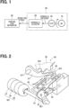
- FIG. 1 is a basic configuration diagram illustrating an integrated pump device 90 of the present embodiment.
- the integrated pump device 90 is integrally configured by the motor 10, the oil pump 30, and the hydraulic actuator 60.
- the motor is denoted by "M” and the electric oil pump by "EOP".
- the oil pump 30 is an electric oil pump and discharges oil drawn from an oil pan by a driving force of the motor 10.
- the hydraulic actuator 60 switches between an advance state and a retard state by a hydraulic pressure created by the oil pump 30.
- advance state and “retard state” are merely terms for distinguishing opposite states for convenience, and either state may be defined as the advance state or the retard state.
- the hydraulic actuator 60 of the present embodiment is a parking lock actuator which operates a parking lock mechanism 80 of an automobile.
- the hydraulic actuator 60 provides an actuating force to the parking lock mechanism 80 such that the hydraulic actuator 60 locks the parking lock mechanism 80 at the advance state and unlocks the parking lock mechanism 80 at the retard state.
- a shift range is operated to a P range, it corresponds to the time of being locked, and when the shift range is operated to a not-P range (i.e., notP range), it corresponds to the time of being unlocked.
- the not-P range is one range in the two-position configuration.
- a plurality of ranges other than the P range may be collectively interpreted as the not-P range.
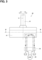
- FIG. 2 is a configuration diagram illustrating the integrated pump device 901 and the parking lock mechanism 80 of the first embodiment.
- the integrated pump device 901 includes the hydraulic actuator 60 of a rotary type having a cylindrical outer shape.
- the integrated pump device 901 is integrally formed by the motor 10, the oil pump 30, and the hydraulic actuator 60.
- the motor 10, the oil pump 30, and the hydraulic actuator 60 are arranged coaxially and in series and integrally constructed, but they may be arranged in series and integrally constructed with their axes shifted, or may be arranged in parallel and integrally constructed.
- the parking lock mechanism 80 includes a detent shaft 81, a detent plate 82, a detent spring 83, a switching rod 84, a parking rod 85, a cone 86, a parking lock pole 87, and a parking gear 88.
- the detent shaft 81 is an output shaft of the hydraulic actuator 60, and rotates in both directions within a predetermined angular range when the hydraulic actuator 60 is operated.
- the detent plate 82 is fixed to the detent shaft 81 and rotates together with the detent shaft 81.
- the detent plate 82 has recesses 823 at portions close to the detent spring 83.
- a rotational force greater than or equal to a predetermined amount is applied to the detent plate 82, the detent spring 83 is elastically deformed, and a detent roller 833 provided at a tip is fitted into one of the recesses 823.
- a pin 824 protruding from a plate surface of the detent plate 82 engages with a groove formed at a tip of the switching rod 84. Note that the pin 824 and the switching rod 84 in the reference embodiment shown in FIG. 19 may be used, or may not be used in the first embodiment.
- the parking rod 85 is formed in a substantially L-shape, and one end 851 is fixed to the detent plate 82.
- the other end 852 of the parking rod 85 is provided at the cone 86.
- the cone 86 is formed so as to decrease in diameter as toward the other end 852.
- the parking lock pole 87 is in contact with a conical surface of the cone 86 and is provided so as to be swingable around a shaft part 877.
- a protrusion 878 that can mesh with the parking gear 88 is provided on the parking lock pole 87.
- FIGS. 3 and 4 show an operation completion state at the time of being unlocked when the shift range is operated from the P range to the not-P range.
- the lower part of FIG. 4 shows the operation completion state at the time of being locked when the shift range is operated from the not-P range to the P range.
- the hydraulic actuator 60 includes a housing 61 having a cylindrical centered on a rotation axis O and a vane rotor 63 coaxially accommodated in the housing 61.
- the housing 61 has, for example, four vane chambers 621 to 624 arranged in the circumferential direction.
- the vane chambers 621 to 624 are fan-shaped with radially outside inner walls each formed in an arc shape. In FIG. 4 , lead wires of reference numerals of the vane chambers 621 to 624 are led out from the radially outside inner wall.
- the vane rotor 63 has four vanes 641 to 644, for example.
- the four vanes 641 to 644 are provided on an outer periphery of the vane rotor 63 respectively corresponding to the vane chambers 621 to 624.
- One vane 641 of the four vanes 641 to 644 includes stoppers 645, 646 provided at both ends in the circumferential direction for restricting a rotation of the vane 641, and is formed larger than the other three vanes 642, 643, 644.
- the other three vanes 642, 643, 644 are formed relatively small in order to secure a volume of a hydraulic chamber.
- a sealing material is provided on a sliding portion of a radial outer wall of each of the vanes 641 to 644.
- the vanes 641 to 644 are capable of rotating in a circumferential direction in the corresponding vane chambers 621 to 624.
- Advance chambers 651 to 654 are formed in one circumferential direction of the vanes 641 to 644 in the vane chambers 621 to 624, respectively.
- Retard chambers 661 to 664 are formed in the other circumferential direction of the vanes 641 to 644.
- the advance chambers 651 to 654 are connected to a common advance port via distribution oil passages.
- the retard chambers 661 to 664 are connected to a common return port via the distribution oil passages.
- Hydraulic pressure is supplied to the retard chambers 661 to 664 hatched with dashed lines at the time of being unlocked shown in the upper part of FIG. 4 .
- the vane rotor 63 rotates in a counterclockwise direction in the FIG. 4 to the retard state, and the parking lock mechanism 80 is unlocked.
- the Oil is discharged from the advance chambers 651 to 654.
- a two-dot chain line arrow in FIG. 3 schematically indicates a flow of the oil at this time.
- the hydraulic pressure is supplied to the advance chambers 651 to 654 hatched with dashed lines at the time of being locked shown in the lower part of FIG. 4 .
- the vane rotor 63 rotates in a clockwise direction in the FIG. 4 to be in the advance state, and the parking lock mechanism 80 is locked.
- the oil is discharged from the retard chambers 661 to 664.
- the dashed-dotted arrows in FIG. 3 schematically indicates the flow of the oil at this time.
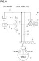
- the oil pump 30 is connected to a motor generator 39 via direct supply passages 35, 38 branched from an oil passage that supplies the hydraulic pressure to the hydraulic actuator 60.
- the motor generator is denoted as "MG" in the drawings and the following specification.
- the MG 39 corresponds to an oil consumption device to which the oil is supplied from the oil pump 30. More specifically, in a stator of the MG 39, the oil is sprayed in an open space so as to cool coils that generate heat when the MG 39 is energized.
- the following first to sixth embodiments are a combination of three patterns of configuration regarding switching of an operating direction of the hydraulic actuator 60 and two patterns of configuration regarding an oil supply route to the MG 39.
- a rotation direction of the oil pump 30 is constant, and the oil drawn from the oil pan 31 via a suction oil passage 32 flows through a suction port 342 to a discharge port 343 only in one direction.
- a directional control valve 56 is provided between the oil pump 30 and the hydraulic actuator 60 to switch a flow of the oil from the oil pump 30 to the advance chambers 651 to 654 and the retard chambers 661 to 664.
- a port shown in the middle is connected to the discharge port 343 of the oil pump 30 via an actuator oil passage 360.
- two ports shown on two sides are connected to the suction oil passage 32 via actuator oil passages 365, 366, respectively.
- a supply switching valve 50 for switching between communication and blocking of direct supply passages 35, 38 are provided in the direct supply passages 35, 38.
- One of the direct supply passages 35, 38, positioned on a side of the oil pump 30, that is, at an upstream side of the supply switching valve 50 is referred to as the "discharge oil passage 35".
- the other one of the direct supply passages 35, 38, positioned on a side of the MG 39 from the supply switching valve 50, that is, at a downstream side of the supply switching valve 50, is referred to as "arrival oil passage 38".
- the use of a circulation oil passage 37 indicated by the dashed line between the supply switching valve 50 and the suction oil passage 32 is basically not assumed. That is, the lowest mode among the three switching modes that constitute the supply switching valve 50 may not be used.
- the discharge oil passage 35 communicates with or is blocked from the arrival oil passage 38.
- the supply switching valve 50 may be configured integrally as a module of the integrated pump device 901.
- the supply switching valve 50 is operated to a position where the direct supply passages 35, 38 communicate with each other.
- the directional control valve 56 is operated to a position where the actuator oil passage 360 is connected to the retard chambers 661 to 664 and the actuator oil passage 365 is connected to the advance chambers 651 to 654.
- the oil discharged from the discharge port 343 of the oil pump 30 is supplied to the MG 39 via the direct supply passages 35, 38, and is also supplied to the retard chambers 661 to 664 of the hydraulic actuator 60 via the actuator oil passage 360.
- the oil is returned to the suction oil passage 32 from the advance chambers 651 to 654 of the hydraulic actuator 60 via the actuator oil passage 365.
- the hydraulic actuator 60 becomes in the retard state, and the parking lock mechanism 80 is unlocked.
- the supply switching valve 50 is operated to a position where the direct supply passages 35, 38 are cut off.
- the directional control valve 56 is operated to a position where the actuator oil passage 360 is connected to the advance chambers 651 to 654 and the actuator oil passage 366 is connected to the retard chambers 661 to 664.
- the oil discharged from the discharge port 343 of the oil pump 30 is supplied to the advance chambers 651 to 654 of the hydraulic actuator 60 via the actuator oil passage 360.
- the oil is returned to the suction oil passage 32 from the retard chambers 661 to 664 of the hydraulic actuator 60 via the actuator oil passage 366.
- the hydraulic actuator 60 becomes in the advance state, and the parking lock mechanism 80 is locked.
- the operating force of the hydraulic actuator is determined by a product of a pressure receiving area and a hydraulic pressure.
- the pressure receiving area can be secured by the plurality of vanes 641 to 644, and the hydraulic actuator 60 can be downsized. Therefore, the hydraulic actuator is particularly effectively applied such as a parking lock actuator where the mounting space is restricted.
- the switching of the operation direction of the hydraulic actuator 60 can be reliably performed by using the directional control valve 56.
- the supply switching valve 50 provided in the direct supply passages 35, 38 is used.
- the supply of cooling oil to the MG 39 can be switched at any timing since the MG 39 can be performed independently of the operation of the hydraulic actuator 60.
- a second embodiment will be described with reference to FIGS. 7 to 10 .
- An integrated pump device 902 of the second embodiment differs from the first embodiment in a route for supplying oil to a MG 39 as an oil consumption device.
- a supply switching valve 50 is not provided.
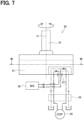
- FIGS. 7 and 8 correspond to FIGS. 3 and 4 of the first embodiment, respectively.
- a vane chamber 621 in which a vane 641 operates has a communication port 67 formed in a middle part in a rotation direction between an advance chamber 651 and a retard chamber 661.
- the communication port 67 may be formed not only in one vane chamber 621 but also in a plurality of vane chambers.
- the communication port 67 is connected to the MG 39 via a sub-supply passage 68.
- a consumption check valve 69 is provided at the sub-supply passage 68 and prevents a reverse flow of the oil from the MG 39 to the hydraulic actuator 60.
- the consumption check valve 69 is not limited to one, and a plurality of consumption check valves may be provided.
- an unlocked state shown on the upper part of FIG. 8 is an initial state of rotation of the vane rotor 63 at the time of being locked.
- a locked state shown on the lower part of FIG. 8 is the initial state of rotation of the vane rotor 63 at the time of being unlocked.
- a two-dot chain line arrow in FIG. 7 schematically indicates a flow of the oil when shifting from a locked state to an unlocked state.
- a dashed-dotted line arrow schematically indicates the flow of oil when shifting from the unlocked state to the locked state.
- the vane 641 closes the communication port 67 in the hydraulic chamber which is the retard chamber 661, to which hydraulic pressure is supplied from the oil pump 30.
- the communication port 67 is opened in the retard chamber 661 at a certain rotational position. Then, at least part of the oil supplied from the oil pump 30 to the retard chamber 661 flows out from the communication port 67 and is supplied to the MG 39 via the sub-supply passage 68.
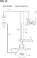
- the vane 641 closes the communication port 67 in the hydraulic chamber, which is the advance chamber 651, to which the hydraulic pressure is supplied from the oil pump 30.
- the communication port 67 is opened in the advance chamber 651 at a certain rotational position. Then, at least part of the oil supplied from the oil pump 30 to the advance chamber 651 flows out from the communication port 67 and is supplied to the MG 39 via the sub-supply passage 68.
- the oil passage from the oil pump 30 to the MG 39 and the oil passage from the oil pump 30 to the hydraulic actuator 60 are provided in parallel.
- the oil passages are provided in series so as to connect the oil pump 30 to the MG 39 via the hydraulic actuator 60.
- An integrated pump device 903 of the third embodiment differs from the first embodiment in a configuration of a hydraulic circuit for switching an operating direction of a hydraulic actuator 60.
- An oil pump 30 can rotate in both a forward direction and a reverse direction together with rotation of a motor 10, and a suction port and a discharge port are alternatively switched in accordance with a change of a rotation direction of the oil pump 30. That is, a forward suction port 342 is a reverse discharge port, and a reverse suction port 343 is a forward discharge port.
- a rotation direction of the first embodiment that is, the rotation direction of the oil pump 30 in which oil is supplied to the MG 39 directly from the forward discharge port 343 via the direct supply passages 35, 38 is a forward direction.
- the supply switching valve 50 switches between communication and blocking of the direct supply passages 35, 38 similarly to the first embodiment.
- the forward suction port 342 is connected to advance chambers 651 to 654 of the hydraulic actuator 60 via an actuator oil passage 367.
- the forward suction passage 32 connected to the forward suction port 342 is provided with a suction check valve 57 that prevents a reverse flow from the oil pump 30 to the oil pan 31.
- the reverse suction port 343 is connected to the retard chambers 661 to 664 of the hydraulic actuator 60 via an actuator oil passage 368.
- a suction check valve 58 that prevents a reverse flow from the oil pump 30 to the oil pan 31 is provided at the reverse suction passage 33 connected to the reverse suction port 343.
- one end of each of the forward suction passage 32 and the reverse suction passage 33 is connected to the oil pan 31.
- the forward suction passage 32 and the reverse suction passage 33 may branch from a common suction oil passage connected to the oil pan 31.
- the supply switching valve 50 is operated to a position where the direct supply passages 35, 38 communicate with each other.
- the oil pump 30 rotates forward, the oil is drawn from the oil pan 31 into the forward suction port 342 via the forward suction passage 32.
- the oil discharged from the forward discharge port 343 of the oil pump 30 is supplied to the MG 39 via the direct supply passages 35, 38, and is also supplied to the retard chamber 661 to 664 of the hydraulic actuator 60 via the actuator oil passage 368.
- the suction check valve 58 prevents the oil from flowing back to the oil pan 31 through the reverse suction passage 33, as indicated by an "x" mark in FIG. 11 .
- the oil is returned to the forward suction passage 32 from the advance chambers 651 to 654 of the hydraulic actuator 60 via the actuator oil passage 367.
- the hydraulic actuator 60 becomes in the retard state, and the parking lock mechanism 80 is unlocked.
- the supply switching valve 50 is operated to a position where the direct supply passages 35, 38 are cut off.
- the oil pump 30 reverses, the oil is drawn from the oil pan 31 into the reverse suction port 343 via the reverse suction passage 33.
- the oil discharged from the reverse discharge port 342 is supplied to the advance chambers 651 to 654 of the hydraulic actuator 60 via the actuator oil passage 367.
- the suction check valve 57 prevents the oil from flowing back to the oil pan 31 through the forward suction passage 32, as indicated by an "x" mark in FIG. 12 .
- the oil is returned to the reverse suction port 343 from the retard chambers 661 to 664 of the hydraulic actuator 60 via the actuator oil passage 368.
- the hydraulic actuator 60 becomes in the advance state, and the parking lock mechanism 80 is locked.
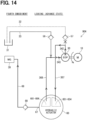
- An integrated pump device 904 of the fourth embodiment combines a configuration for switching an operating direction of a hydraulic actuator 60 according to the third embodiment and a configuration for supplying oil to a MG 39 according to the second embodiment.
- the operating direction of the hydraulic actuator 60 is switched by switching between forward and reverse rotations of the oil pump 30 and using functions of suction check valves 57, 58.
- the oil is supplied to the MG 39 from a communication port 67 formed in the hydraulic actuator 60 via a sub-supply passage 68.
- a consumption check valve 69 is provided in the sub-supply passage 68.
- the oil discharged from a forward discharge port 343 is supplied to retard chambers 661 to 664 of the hydraulic actuator 60 via the actuator oil passage 368.
- the communication port 67 is closed to block communication between the oil pump 30 and the MG 39. After the vane rotor 63 starts rotating, the communication port 67 is opened, and the oil pump 30 and the MG 39 communicate with each other.
- the oil discharged from a reverse discharge port 342 is supplied to advance chambers 651 to 654 of the hydraulic actuator 60 via the actuator oil passage 367.
- the communication port 67 is closed to block communication between the oil pump 30 and the MG 39. After the vane rotor 63 starts rotating, the communication port 67 is opened, and the oil pump 30 and the MG 39 communicate with each other.
- a directional control valve 56 can be omitted.
- the hydraulic pressure supplied to the hydraulic actuator 60 is ensured by preventing backflow of oil to a suction using the suction check valves 57, 58.
- the suction check valves 57, 58 is not limited to one in each of the suction oil passages 32, 33 and a plurality of suction check valves may be provided.
- An integrated pump device 905 of the fifth embodiment differs from the first and third embodiments in a configuration of a hydraulic circuit for switching an operating direction of a hydraulic actuator 60.
- An oil pump 30 can rotate in both a forward direction and a reverse direction together with rotation of a motor 10, and a suction port and a discharge port are alternatively switched in accordance with a change of a rotation direction of the oil pump 30 similarly to the third embodiment.
- a connection structure of a forward suction port 342 and a reverse suction port 343 of the oil pump 30 with the hydraulic actuator 60 is the same as that of the third embodiment.
- a switching valve 59 in place of suction check valves 57, 58 of the third embodiment is provided at a forward suction passage 32 and a reverse suction passage 33.
- the switching valve 59 allows the oil to flow in the forward suction passage 32 and blocks the oil from flowing in the reverse suction passage 33 while the oil pump 30 rotates in a forward direction, and allows the oil to flow in the reverse suction passage 33 and blocks the oil from flowing in the forward suction passage 32 while the oil pump 30 rotates in the reverse direction.
- the switching valve 59 may be configured integrally as a module of the integrated pump device 905.
- the switching valve 59 is not limited to an electromagnetic valve, and may be a hydraulic switching valve that switches a spool depending on operating pressure.
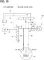
- the supply switching valve 50 is operated to a position where the direct supply passages 35, 38 communicate with each other.
- the switching valve 59 is made to open the forward suction passage 32.
- the oil pump 30 rotates forward, the oil is drawn from the oil pan 31 into the forward suction port 342 via the forward suction passage 32.
- the oil discharged from the forward discharge port 343 of the oil pump 30 is supplied to the MG 39 via the direct supply passages 35, 38, and is also supplied to the retard chamber 661 to 664 of the hydraulic actuator 60 via the actuator oil passage 368.
- the switching valve 59 closes the reverse suction passage 33 as indicated by an "x" mark in FIG. 15 .
- the oil is returned to the forward suction passage 32 from the advance chambers 651 to 654 of the hydraulic actuator 60 via the actuator oil passage 367.
- the hydraulic actuator 60 becomes in the retard state, and the parking lock mechanism 80 is unlocked.
- the supply switching valve 50 is operated to a position where the direct supply passages 35, 38 are cut off.
- the switching valve 59 can open the reverse suction passage 33.
- the oil pump 30 reverses, the oil is drawn from the oil pan 31 into the reverse suction port 343 via the reverse suction passage 33.
- the oil discharged from the reverse discharge port 342 is supplied to the advance chambers 651 to 654 of the hydraulic actuator 60 via the actuator oil passage 367.
- the switching valve 59 closes the forward suction passage 32 as indicated by an "x" mark in FIG. 16 .
- the oil is returned to the reverse suction passage 33 from the retard chambers 661 to 664 of the hydraulic actuator 60 via the actuator oil passage 368.
- the hydraulic actuator 60 becomes in the advance state, and the parking lock mechanism 80 is locked.
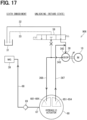
- An integrated pump device 906 of the sixth embodiment combines a configuration for switching an operating direction of a hydraulic actuator 60 according to the fifth embodiment and a configuration for supplying oil to a MG 39 according to the second embodiment.
- the operating direction of the hydraulic actuator 60 is switched by switching between forward and reverse rotations of the oil pump 30 and by an associated change of the switching valve 59.
- the oil is supplied to the MG 39 from a communication port 67 formed in the hydraulic actuator 60 via a sub-supply passage 68.
- a consumption check valve 69 is provided in the sub-supply passage 68.
- the oil discharged from a forward discharge port 343 is supplied to retard chambers 661 to 664 of the hydraulic actuator 60 via the actuator oil passage 368.
- the communication port 67 is closed to block communication between the oil pump 30 and the MG 39. After the vane rotor 63 starts rotating, the communication port 67 is opened, and the oil pump 30 and the MG 39 communicate with each other.
- the oil discharged from a reverse discharge port 342 is supplied to advance chambers 651 to 654 of the hydraulic actuator 60 via the actuator oil passage 367.
- the communication port 67 is closed to block communication between the oil pump 30 and the MG 39. After the vane rotor 63 starts rotating, the communication port 67 is opened, and the oil pump 30 and the MG 39 communicate with each other.
- a directional control valve 56 can be omitted.
- the hydraulic pressure supplied to the hydraulic actuator 60 is ensured by preventing backflow of oil to a suction using the switching valve 59.
- the cylinder type hydraulic actuator 70 includes a cylinder 71 and a piston 73 that reciprocates in the cylinder 71.
- An advance chamber 75 is provided in an area of the cylinder 71 in the axial direction of the piston 73, and a retard chamber 76 is provided in an another area of the cylinder 71 in the axial direction of the piston 73.
- the piston 73 is linked to a switching rod 84 of a parking lock mechanism 80 as indicated by the thick arrow in FIG 19 .
- a tip of the switching rod 84 is engaged with a pin 824 provided on a detent plate 82.
- the switching rod 84 reciprocates with the reciprocating movement of the piston 73, the detent plate 82 rotates via the pin 824 and the parking rod 85 moves, thereby switching between a P range and a not-P range.
- An oil pump 30 can supply oil to the advance chamber 75 and the retard chamber 76 via ports 721, 722. A flow of the oil to each hydraulic chamber 75, 76 is switched based on movements of a rotary hydraulic actuator 60 of the first or second embodiment. The oil in the hydraulic chamber on the discharge side is returned to the suction side of the oil pump 30. In FIG. 19 , illustration of the oil flow switching path is omitted.
- the hydraulic actuator operates in the same manner as in the first to sixth embodiments.
- the reference embodiment differs from the first to sixth embodiments in that it is not intended to reduce a size of the integrated pump device.
Landscapes
- Engineering & Computer Science (AREA)
- General Engineering & Computer Science (AREA)
- Mechanical Engineering (AREA)
- Physics & Mathematics (AREA)
- Fluid Mechanics (AREA)
- Transportation (AREA)
- Valve Device For Special Equipments (AREA)
- Control Of Transmission Device (AREA)
- Gear-Shifting Mechanisms (AREA)
- Valves And Accessory Devices For Braking Systems (AREA)
- Actuator (AREA)
- Braking Arrangements (AREA)
Abstract
Description
- The present application is based on
Japanese Patent Application No. 2020-209129 filed on December 17, 2020 - The present disclosure relates to an integrated pump device.
- A hydraulic system integrating a motor, an electric oil pump, and a hydraulic actuator is known. For example, in a hydraulic system for an automobile disclosed in
Patent Literature 1, a motor, an electric oil pump, a hydraulic parking lock actuator, and a clutch-engagement control oil passage are integrated. When the motor rotates in a forward direction, the hydraulic parking lock actuator and a clutch operate. When the motor rotates in a reverse direction, an oil for cooling a motor generator is supplied from the oil pump. - Patent Literature 1:
WO 20201043235 A - In the hydraulic system of
Patent Literature 1, a cylinder-type hydraulic parking lock actuator in which a piston reciprocates in a cylinder is used. Therefore, a body size for securing a pressure receiving area and a stroke length increases. - An object of the present disclosure is to provide an integrated pump device in which a hydraulic actuator integrated with a motor and an electric oil pump is downsized.
- An integrated pump device of the present disclosure is a module in which a motor, an oil pump, and a hydraulic actuator are integrated with each other. For example, in a case of the integrated pump device mounted on an automobile, the term "a module" does not necessarily mean a unit which is delivered to an automobile manufacturer as one component. The term "a module" may be interpreted as what are delivered in parts and integrated into the automobile after being installed in the automobile.
- The oil pump discharges oil drawn from an oil pan by a driving force of the motor. The hydraulic actuator switches between an advance state and a retard state by a hydraulic pressure created by the oil pump. For example, the hydraulic actuator is a parking lock actuator which operates a parking lock mechanism of an automobile.
- The hydraulic actuator includes a housing having one or more vane chambers, and a vane rotor housed in the housing and including on one or more vanes arranged in the vane chambers.
- The vane is capable of rotating in a circumferential direction of the vane in the corresponding vane chamber. An advance chamber is provided in an area of the vane chamber in the circumferential direction, and a retard chamber is provided in an another area of the vane chamber in the circumferential direction. When the hydraulic pressure in the advance chamber is higher than in the retard chamber, the vane rotor rotates in one direction to enter the advance state; and when the hydraulic pressure in the retard chamber is higher than in the advance chamber, the vane rotor rotates in the other direction to enter the retard state.
- The operating force of a hydraulic actuator is determined by the product of the pressure receiving area and the hydraulic pressure. In the present disclosure, by using a rotary hydraulic actuator, the pressure receiving area can be secured by one or more vanes, and the size of the hydraulic actuator can be reduced. Therefore, the hydraulic actuator is particularly effectively applied such as a parking lock actuator where the mounting space is restricted.
- The above and other objectives, features and advantages of the present disclosure will become more apparent from the following detailed description with reference to the accompanying drawings. In the drawings:
-
FIG. 1 is a basic configuration diagram illustrating an integrated pump device according to the present embodiment; -
FIG. 2 is a configuration diagram illustrating the integrated pump device and a parking lock mechanism according to first to sixth embodiments; -
FIG. 3 is a diagram illustrating an appearance of a rotary hydraulic actuator and a flow of oil according to the first, third and fifth embodiments; -
FIG. 4 is a cross-sectional view taken along line IV-IV ofFIG. 3 at the time of being unlocked (retard state) and locked (advance state) of the first, third, and fifth embodiments; -
FIG. 5 is a diagram showing a hydraulic path at the time of being unlocked (retard state) according to the first embodiment; -
FIG. 6 is a diagram showing a hydraulic path at the time of being unlocked (advance state) according to the first embodiment; -
FIG. 7 is a diagram illustrating an appearance of a rotary hydraulic actuator and a flow of oil according to the second, fourth and sixth embodiments; -
FIG. 8 is a cross-sectional view taken along line VIII-V III ofFIG. 7 at the time of being unlocked (retard state) and locked (advance state) of the second, fourth, and sixth embodiments; -
FIG. 9 is a diagram showing a hydraulic path at the time of being unlocked (retard state) according to the second embodiment; -
FIG. 10 is a diagram showing a hydraulic path at the time of being locked (advance state) according to the second embodiment; -
FIG. 11 is a diagram showing a hydraulic path at the time of being unlocked (retard state) according to the third embodiment; -
FIG. 12 is a diagram showing a hydraulic path at the time of being locked (advance state) according to the third embodiment; -
FIG. 13 is a diagram showing a hydraulic path at the time of being unlocked (retard state) according to the fourth embodiment; -
FIG. 14 is a diagram showing a hydraulic path at the time of being locked (advance state) according to the fourth embodiment; -
FIG. 15 is a diagram showing a hydraulic path at the time of being unlocked (retard state) according to the fifth embodiment; -
FIG. 16 is a diagram showing a hydraulic path at the time of being locked (advance state) according to the fifth embodiment; -
FIG. 17 is a diagram showing a hydraulic path at the time of being unlocked (retard state) according to the sixth embodiment; -
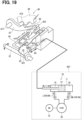
FIG. 18 is a diagram showing a hydraulic path at the time of being locked (advance state) according to the sixth embodiment; and -
FIG. 19 is a configuration diagram of an integrated pump device and a parking lock mechanism using a cylinder type hydraulic actuator according to a reference embodiment. - An integrated pump device according to the present disclosure will be described with reference to plural embodiments based on the drawings. In the multiple embodiments, substantially the same components are denoted by the same reference numerals, and a description of the same components will be omitted. The following first to sixth embodiments are collectively referred to as "present embodiment". The integrated pump device of the present embodiment is a module in which a motor, an electric oil pump, and a hydraulic actuator are configured to be integrated.
-
FIG. 1 is a basic configuration diagram illustrating an integratedpump device 90 of the present embodiment. The integratedpump device 90 is integrally configured by themotor 10, theoil pump 30, and thehydraulic actuator 60. InFIG. 1 , the motor is denoted by "M" and the electric oil pump by "EOP". - The
oil pump 30 is an electric oil pump and discharges oil drawn from an oil pan by a driving force of themotor 10. - The
hydraulic actuator 60 switches between an advance state and a retard state by a hydraulic pressure created by theoil pump 30. Here, "advance state" and "retard state" are merely terms for distinguishing opposite states for convenience, and either state may be defined as the advance state or the retard state. - The
hydraulic actuator 60 of the present embodiment is a parking lock actuator which operates aparking lock mechanism 80 of an automobile. Thehydraulic actuator 60 provides an actuating force to theparking lock mechanism 80 such that thehydraulic actuator 60 locks theparking lock mechanism 80 at the advance state and unlocks theparking lock mechanism 80 at the retard state. When a shift range is operated to a P range, it corresponds to the time of being locked, and when the shift range is operated to a not-P range (i.e., notP range), it corresponds to the time of being unlocked. Here, the not-P range is one range in the two-position configuration. In addition, in a configuration including a multi-shift range, a plurality of ranges other than the P range may be collectively interpreted as the not-P range. - Hereinafter, the reference numerals of the integrated pump device of first to sixth embodiments are "901" to "906" corresponding to the respective embodiments. Firstly, the first embodiment will be described with reference to
FIG. 2 to FIG. 6 .FIG. 2 is a configuration diagram illustrating theintegrated pump device 901 and theparking lock mechanism 80 of the first embodiment. Theintegrated pump device 901 includes thehydraulic actuator 60 of a rotary type having a cylindrical outer shape. Theintegrated pump device 901 is integrally formed by themotor 10, theoil pump 30, and thehydraulic actuator 60. InFIG. 2 , themotor 10, theoil pump 30, and thehydraulic actuator 60 are arranged coaxially and in series and integrally constructed, but they may be arranged in series and integrally constructed with their axes shifted, or may be arranged in parallel and integrally constructed. - The
parking lock mechanism 80 includes adetent shaft 81, adetent plate 82, adetent spring 83, a switchingrod 84, aparking rod 85, acone 86, aparking lock pole 87, and aparking gear 88. Thedetent shaft 81 is an output shaft of thehydraulic actuator 60, and rotates in both directions within a predetermined angular range when thehydraulic actuator 60 is operated. Thedetent plate 82 is fixed to thedetent shaft 81 and rotates together with thedetent shaft 81. - The
detent plate 82 hasrecesses 823 at portions close to thedetent spring 83. When a rotational force greater than or equal to a predetermined amount is applied to thedetent plate 82, thedetent spring 83 is elastically deformed, and adetent roller 833 provided at a tip is fitted into one of therecesses 823. As a result, a rotation of thedetent plate 82 is restricted. Apin 824 protruding from a plate surface of thedetent plate 82 engages with a groove formed at a tip of the switchingrod 84. Note that thepin 824 and the switchingrod 84 in the reference embodiment shown inFIG. 19 may be used, or may not be used in the first embodiment. - The
parking rod 85 is formed in a substantially L-shape, and oneend 851 is fixed to thedetent plate 82. Theother end 852 of theparking rod 85 is provided at thecone 86. Thecone 86 is formed so as to decrease in diameter as toward theother end 852. When thedetent plate 82 rotates in a direction in which thedetent roller 833 fits into a recess corresponding to the P range, thecone 86 moves in the direction of an arrow P inFIG. 2 . - The
parking lock pole 87 is in contact with a conical surface of thecone 86 and is provided so as to be swingable around ashaft part 877. Aprotrusion 878 that can mesh with theparking gear 88 is provided on theparking lock pole 87. When thecone 86 moves in the direction of the arrow P, theparking lock pole 87 is pushed up and theprotrusion 878 and theparking gear 88 mesh with each other. As a result, theparking lock pole 87 is in a locked state. On the other hand, when thecone 86 moves in a direction of an arrow notP, the meshing between theprotrusion 878 and theparking gear 88 is released. As a result, theparking lock pole 87 is in an unlocked state. - Next, a configuration example of the rotary
hydraulic actuator 60 will be described with reference toFIGS. 3 and4 . The configurations ofFIGS. 3 and4 are also common in third and fifth embodiments described later. The upper part ofFIG. 4 shows an operation completion state at the time of being unlocked when the shift range is operated from the P range to the not-P range. The lower part ofFIG. 4 shows the operation completion state at the time of being locked when the shift range is operated from the not-P range to the P range. - The
hydraulic actuator 60 includes ahousing 61 having a cylindrical centered on a rotation axis O and avane rotor 63 coaxially accommodated in thehousing 61. Thehousing 61 has, for example, fourvane chambers 621 to 624 arranged in the circumferential direction. Thevane chambers 621 to 624 are fan-shaped with radially outside inner walls each formed in an arc shape. InFIG. 4 , lead wires of reference numerals of thevane chambers 621 to 624 are led out from the radially outside inner wall. - The
vane rotor 63 has fourvanes 641 to 644, for example. The fourvanes 641 to 644 are provided on an outer periphery of thevane rotor 63 respectively corresponding to thevane chambers 621 to 624. Onevane 641 of the fourvanes 641 to 644 includesstoppers vane 641, and is formed larger than the other threevanes vanes vanes 641 to 644. - The
vanes 641 to 644 are capable of rotating in a circumferential direction in the correspondingvane chambers 621 to 624.Advance chambers 651 to 654 are formed in one circumferential direction of thevanes 641 to 644 in thevane chambers 621 to 624, respectively.Retard chambers 661 to 664 are formed in the other circumferential direction of thevanes 641 to 644. Although not shown, theadvance chambers 651 to 654 are connected to a common advance port via distribution oil passages. Similarly, theretard chambers 661 to 664 are connected to a common return port via the distribution oil passages. - Hydraulic pressure is supplied to the
retard chambers 661 to 664 hatched with dashed lines at the time of being unlocked shown in the upper part ofFIG. 4 . As a result, thevane rotor 63 rotates in a counterclockwise direction in theFIG. 4 to the retard state, and theparking lock mechanism 80 is unlocked. The Oil is discharged from theadvance chambers 651 to 654. A two-dot chain line arrow inFIG. 3 schematically indicates a flow of the oil at this time. - The hydraulic pressure is supplied to the
advance chambers 651 to 654 hatched with dashed lines at the time of being locked shown in the lower part ofFIG. 4 . As a result, thevane rotor 63 rotates in a clockwise direction in theFIG. 4 to be in the advance state, and theparking lock mechanism 80 is locked. The oil is discharged from theretard chambers 661 to 664. The dashed-dotted arrows inFIG. 3 schematically indicates the flow of the oil at this time. - Next, reference is made to
FIGS. 5 and6 . Theoil pump 30 is connected to amotor generator 39 viadirect supply passages hydraulic actuator 60. The motor generator is denoted as "MG" in the drawings and the following specification. TheMG 39 corresponds to an oil consumption device to which the oil is supplied from theoil pump 30. More specifically, in a stator of theMG 39, the oil is sprayed in an open space so as to cool coils that generate heat when theMG 39 is energized. - The following first to sixth embodiments are a combination of three patterns of configuration regarding switching of an operating direction of the
hydraulic actuator 60 and two patterns of configuration regarding an oil supply route to theMG 39. Regarding the switching of the operating direction of thehydraulic actuator 60, in the first and second embodiments, a rotation direction of theoil pump 30 is constant, and the oil drawn from theoil pan 31 via asuction oil passage 32 flows through asuction port 342 to adischarge port 343 only in one direction. - A
directional control valve 56 is provided between theoil pump 30 and thehydraulic actuator 60 to switch a flow of the oil from theoil pump 30 to theadvance chambers 651 to 654 and theretard chambers 661 to 664. Of three inlet ports of thedirectional control valve 56, a port shown in the middle is connected to thedischarge port 343 of theoil pump 30 via anactuator oil passage 360. Of the three inlet ports, two ports shown on two sides are connected to thesuction oil passage 32 viaactuator oil passages - Further, with respect to an oil supply route to the
MG 39, in the first, third, and fifth embodiments, asupply switching valve 50 for switching between communication and blocking ofdirect supply passages direct supply passages direct supply passages oil pump 30, that is, at an upstream side of thesupply switching valve 50 is referred to as the "discharge oil passage 35". The other one of thedirect supply passages MG 39 from thesupply switching valve 50, that is, at a downstream side of thesupply switching valve 50, is referred to as "arrival oil passage 38". In the first, third, and fifth embodiments, the use of acirculation oil passage 37 indicated by the dashed line between thesupply switching valve 50 and thesuction oil passage 32 is basically not assumed. That is, the lowest mode among the three switching modes that constitute thesupply switching valve 50 may not be used. Thedischarge oil passage 35 communicates with or is blocked from thearrival oil passage 38. Thesupply switching valve 50 may be configured integrally as a module of theintegrated pump device 901. - At the time of being unlocked as shown in
FIG. 5 , thesupply switching valve 50 is operated to a position where thedirect supply passages directional control valve 56 is operated to a position where theactuator oil passage 360 is connected to theretard chambers 661 to 664 and theactuator oil passage 365 is connected to theadvance chambers 651 to 654. The oil discharged from thedischarge port 343 of theoil pump 30 is supplied to theMG 39 via thedirect supply passages retard chambers 661 to 664 of thehydraulic actuator 60 via theactuator oil passage 360. In addition, the oil is returned to thesuction oil passage 32 from theadvance chambers 651 to 654 of thehydraulic actuator 60 via theactuator oil passage 365. Thus, thehydraulic actuator 60 becomes in the retard state, and theparking lock mechanism 80 is unlocked. - At the time of being locked as shown in
FIG. 6 , thesupply switching valve 50 is operated to a position where thedirect supply passages directional control valve 56 is operated to a position where theactuator oil passage 360 is connected to theadvance chambers 651 to 654 and theactuator oil passage 366 is connected to theretard chambers 661 to 664. The oil discharged from thedischarge port 343 of theoil pump 30 is supplied to theadvance chambers 651 to 654 of thehydraulic actuator 60 via theactuator oil passage 360. In addition, the oil is returned to thesuction oil passage 32 from theretard chambers 661 to 664 of thehydraulic actuator 60 via theactuator oil passage 366. Thus, thehydraulic actuator 60 becomes in the advance state, and theparking lock mechanism 80 is locked. - The operating force of the hydraulic actuator is determined by a product of a pressure receiving area and a hydraulic pressure. By using the rotary
hydraulic actuator 60, the pressure receiving area can be secured by the plurality ofvanes 641 to 644, and thehydraulic actuator 60 can be downsized. Therefore, the hydraulic actuator is particularly effectively applied such as a parking lock actuator where the mounting space is restricted. Those advantages are common in the first to sixth embodiments. - In the first embodiment, the switching of the operation direction of the
hydraulic actuator 60 can be reliably performed by using thedirectional control valve 56. In addition, in the first embodiment, with respect to the oil supply route to theMG 39, thesupply switching valve 50 provided in thedirect supply passages MG 39 can be switched at any timing since theMG 39 can be performed independently of the operation of thehydraulic actuator 60. - A second embodiment will be described with reference to
FIGS. 7 to 10 . Anintegrated pump device 902 of the second embodiment differs from the first embodiment in a route for supplying oil to aMG 39 as an oil consumption device. In the second embodiment, there are nodirect supply passages oil pump 30 and theMG 39 as in the first embodiment. Further, in the second embodiment, asupply switching valve 50 is not provided. - Next, a configuration example of a rotary
hydraulic actuator 60 of the second embodiment will be described with reference toFIGS. 7 and8 . The configurations ofFIGS. 7 and8 are also common in fourth and sixth embodiments described later.FIGS. 7 and8 correspond toFIGS. 3 and4 of the first embodiment, respectively. As shown inFIG. 8 , avane chamber 621 in which avane 641 operates, for example, has acommunication port 67 formed in a middle part in a rotation direction between anadvance chamber 651 and aretard chamber 661. Thecommunication port 67 may be formed not only in onevane chamber 621 but also in a plurality of vane chambers. - As shown in
FIGS. 9 and10 , thecommunication port 67 is connected to theMG 39 via asub-supply passage 68. Aconsumption check valve 69 is provided at thesub-supply passage 68 and prevents a reverse flow of the oil from theMG 39 to thehydraulic actuator 60. Theconsumption check valve 69 is not limited to one, and a plurality of consumption check valves may be provided. - Here, an unlocked state shown on the upper part of
FIG. 8 is an initial state of rotation of thevane rotor 63 at the time of being locked. A locked state shown on the lower part ofFIG. 8 is the initial state of rotation of thevane rotor 63 at the time of being unlocked. A two-dot chain line arrow inFIG. 7 schematically indicates a flow of the oil when shifting from a locked state to an unlocked state. A dashed-dotted line arrow schematically indicates the flow of oil when shifting from the unlocked state to the locked state. - At an initial stage of rotation of the
vane rotor 63 shown inFIG. 9 , thevane 641 closes thecommunication port 67 in the hydraulic chamber which is theretard chamber 661, to which hydraulic pressure is supplied from theoil pump 30. After thevane rotor 63 starts rotating, thecommunication port 67 is opened in theretard chamber 661 at a certain rotational position. Then, at least part of the oil supplied from theoil pump 30 to theretard chamber 661 flows out from thecommunication port 67 and is supplied to theMG 39 via thesub-supply passage 68. - At the time of being locked as shown
FIG. 10 , at the initial stage of rotation of thevane rotor 63, thevane 641 closes thecommunication port 67 in the hydraulic chamber, which is theadvance chamber 651, to which the hydraulic pressure is supplied from theoil pump 30. After thevane rotor 63 starts rotating, thecommunication port 67 is opened in theadvance chamber 651 at a certain rotational position. Then, at least part of the oil supplied from theoil pump 30 to theadvance chamber 651 flows out from thecommunication port 67 and is supplied to theMG 39 via thesub-supply passage 68. - In the first embodiment, the oil passage from the
oil pump 30 to theMG 39 and the oil passage from theoil pump 30 to thehydraulic actuator 60 are provided in parallel. In contrast, in the second embodiment, the oil passages are provided in series so as to connect theoil pump 30 to theMG 39 via thehydraulic actuator 60. By combining them into one route, the configuration of the oil passage can be simplified. Also, by switching the oil supply to theMG 39 using a rotation of thevane rotor 63, thesupply switching valve 50 may be omitted. Therefore, a system including the integrated pumping device can be made more compact. - A third embodiment will be described with reference to
FIGS. 11 and12 . Anintegrated pump device 903 of the third embodiment differs from the first embodiment in a configuration of a hydraulic circuit for switching an operating direction of ahydraulic actuator 60. Anoil pump 30 can rotate in both a forward direction and a reverse direction together with rotation of amotor 10, and a suction port and a discharge port are alternatively switched in accordance with a change of a rotation direction of theoil pump 30. That is, aforward suction port 342 is a reverse discharge port, and areverse suction port 343 is a forward discharge port. - In
FIGS. 11 and12 , for convenience, a rotation direction of the first embodiment, that is, the rotation direction of theoil pump 30 in which oil is supplied to theMG 39 directly from theforward discharge port 343 via thedirect supply passages supply switching valve 50 switches between communication and blocking of thedirect supply passages - The
forward suction port 342 is connected to advancechambers 651 to 654 of thehydraulic actuator 60 via anactuator oil passage 367. Theforward suction passage 32 connected to theforward suction port 342 is provided with asuction check valve 57 that prevents a reverse flow from theoil pump 30 to theoil pan 31. - The
reverse suction port 343 is connected to theretard chambers 661 to 664 of thehydraulic actuator 60 via anactuator oil passage 368. Asuction check valve 58 that prevents a reverse flow from theoil pump 30 to theoil pan 31 is provided at thereverse suction passage 33 connected to thereverse suction port 343. In theFIGS. 11 and12 , one end of each of theforward suction passage 32 and thereverse suction passage 33 is connected to theoil pan 31. Alternatively, theforward suction passage 32 and thereverse suction passage 33 may branch from a common suction oil passage connected to theoil pan 31. - At the time of unlocking as shown in
FIG. 11 , thesupply switching valve 50 is operated to a position where thedirect supply passages oil pump 30 rotates forward, the oil is drawn from theoil pan 31 into theforward suction port 342 via theforward suction passage 32. The oil discharged from theforward discharge port 343 of theoil pump 30 is supplied to theMG 39 via thedirect supply passages retard chamber 661 to 664 of thehydraulic actuator 60 via theactuator oil passage 368. - At this time, the
suction check valve 58 prevents the oil from flowing back to theoil pan 31 through thereverse suction passage 33, as indicated by an "x" mark inFIG. 11 . In addition, the oil is returned to theforward suction passage 32 from theadvance chambers 651 to 654 of thehydraulic actuator 60 via theactuator oil passage 367. Thus, thehydraulic actuator 60 becomes in the retard state, and theparking lock mechanism 80 is unlocked. - At the time of being locked as shown in
FIG. 12 , thesupply switching valve 50 is operated to a position where thedirect supply passages oil pump 30 reverses, the oil is drawn from theoil pan 31 into thereverse suction port 343 via thereverse suction passage 33. The oil discharged from thereverse discharge port 342 is supplied to theadvance chambers 651 to 654 of thehydraulic actuator 60 via theactuator oil passage 367. - At this time, the
suction check valve 57 prevents the oil from flowing back to theoil pan 31 through theforward suction passage 32, as indicated by an "x" mark inFIG. 12 . In addition, the oil is returned to thereverse suction port 343 from theretard chambers 661 to 664 of thehydraulic actuator 60 via theactuator oil passage 368. Thus, thehydraulic actuator 60 becomes in the advance state, and theparking lock mechanism 80 is locked. - A fourth embodiment will be described with reference to
FIGS. 13 and14 . Anintegrated pump device 904 of the fourth embodiment combines a configuration for switching an operating direction of ahydraulic actuator 60 according to the third embodiment and a configuration for supplying oil to aMG 39 according to the second embodiment. The operating direction of thehydraulic actuator 60 is switched by switching between forward and reverse rotations of theoil pump 30 and using functions ofsuction check valves MG 39 from acommunication port 67 formed in thehydraulic actuator 60 via asub-supply passage 68. Aconsumption check valve 69 is provided in thesub-supply passage 68. - At the time of being unlocked as shown in
FIG. 13 , when theoil pump 30 rotates forward, the oil discharged from aforward discharge port 343 is supplied to retardchambers 661 to 664 of thehydraulic actuator 60 via theactuator oil passage 368. At the initial stage of rotation of thevane rotor 63, thecommunication port 67 is closed to block communication between theoil pump 30 and theMG 39. After thevane rotor 63 starts rotating, thecommunication port 67 is opened, and theoil pump 30 and theMG 39 communicate with each other. - At the time of being locked as shown in
FIG. 14 , when theoil pump 30 reverses, the oil discharged from areverse discharge port 342 is supplied to advancechambers 651 to 654 of thehydraulic actuator 60 via theactuator oil passage 367. At the initial stage of rotation of thevane rotor 63, thecommunication port 67 is closed to block communication between theoil pump 30 and theMG 39. After thevane rotor 63 starts rotating, thecommunication port 67 is opened, and theoil pump 30 and theMG 39 communicate with each other. - In the third and fourth embodiments, since the flow of the oil in the operating direction of the
hydraulic actuator 60 is switched by switching between forward and reverse rotation of theoil pump 30, adirectional control valve 56 can be omitted. In addition, the hydraulic pressure supplied to thehydraulic actuator 60 is ensured by preventing backflow of oil to a suction using thesuction check valves suction check valves suction oil passages - A fifth embodiment will be described with reference to
FIGS. 15 and16 . Anintegrated pump device 905 of the fifth embodiment differs from the first and third embodiments in a configuration of a hydraulic circuit for switching an operating direction of ahydraulic actuator 60. Anoil pump 30 can rotate in both a forward direction and a reverse direction together with rotation of amotor 10, and a suction port and a discharge port are alternatively switched in accordance with a change of a rotation direction of theoil pump 30 similarly to the third embodiment. Further, a connection structure of aforward suction port 342 and areverse suction port 343 of theoil pump 30 with thehydraulic actuator 60 is the same as that of the third embodiment. - A switching
valve 59 in place ofsuction check valves forward suction passage 32 and areverse suction passage 33. The switchingvalve 59 allows the oil to flow in theforward suction passage 32 and blocks the oil from flowing in thereverse suction passage 33 while theoil pump 30 rotates in a forward direction, and allows the oil to flow in thereverse suction passage 33 and blocks the oil from flowing in theforward suction passage 32 while theoil pump 30 rotates in the reverse direction. The switchingvalve 59 may be configured integrally as a module of theintegrated pump device 905. The switchingvalve 59 is not limited to an electromagnetic valve, and may be a hydraulic switching valve that switches a spool depending on operating pressure. - At the time of being unlocked as shown in
FIG. 15 , thesupply switching valve 50 is operated to a position where thedirect supply passages valve 59 is made to open theforward suction passage 32. When theoil pump 30 rotates forward, the oil is drawn from theoil pan 31 into theforward suction port 342 via theforward suction passage 32. The oil discharged from theforward discharge port 343 of theoil pump 30 is supplied to theMG 39 via thedirect supply passages retard chamber 661 to 664 of thehydraulic actuator 60 via theactuator oil passage 368. - At this time, the switching
valve 59 closes thereverse suction passage 33 as indicated by an "x" mark inFIG. 15 . In addition, the oil is returned to theforward suction passage 32 from theadvance chambers 651 to 654 of thehydraulic actuator 60 via theactuator oil passage 367. Thus, thehydraulic actuator 60 becomes in the retard state, and theparking lock mechanism 80 is unlocked. - At the time of being locked as shown in
FIG. 16 , thesupply switching valve 50 is operated to a position where thedirect supply passages valve 59 can open thereverse suction passage 33. When theoil pump 30 reverses, the oil is drawn from theoil pan 31 into thereverse suction port 343 via thereverse suction passage 33. The oil discharged from thereverse discharge port 342 is supplied to theadvance chambers 651 to 654 of thehydraulic actuator 60 via theactuator oil passage 367. - At this time, the switching
valve 59 closes theforward suction passage 32 as indicated by an "x" mark inFIG. 16 . In addition, the oil is returned to thereverse suction passage 33 from theretard chambers 661 to 664 of thehydraulic actuator 60 via theactuator oil passage 368. Thus, thehydraulic actuator 60 becomes in the advance state, and theparking lock mechanism 80 is locked. - A sixth embodiment will be described with reference to
FIGS. 17 and18 . Anintegrated pump device 906 of the sixth embodiment combines a configuration for switching an operating direction of ahydraulic actuator 60 according to the fifth embodiment and a configuration for supplying oil to aMG 39 according to the second embodiment. The operating direction of thehydraulic actuator 60 is switched by switching between forward and reverse rotations of theoil pump 30 and by an associated change of the switchingvalve 59. Also, the oil is supplied to theMG 39 from acommunication port 67 formed in thehydraulic actuator 60 via asub-supply passage 68. Aconsumption check valve 69 is provided in thesub-supply passage 68. - At the time of being unlocked as shown in
FIG. 17 , when theoil pump 30 rotates forward, the oil discharged from aforward discharge port 343 is supplied to retardchambers 661 to 664 of thehydraulic actuator 60 via theactuator oil passage 368. At the initial stage of rotation of thevane rotor 63, thecommunication port 67 is closed to block communication between theoil pump 30 and theMG 39. After thevane rotor 63 starts rotating, thecommunication port 67 is opened, and theoil pump 30 and theMG 39 communicate with each other. - At the time of being locked as shown in
FIG. 18 , when theoil pump 30 reverses, the oil discharged from areverse discharge port 342 is supplied to advancechambers 651 to 654 of thehydraulic actuator 60 via theactuator oil passage 367. At the initial stage of rotation of thevane rotor 63, thecommunication port 67 is closed to block communication between theoil pump 30 and theMG 39. After thevane rotor 63 starts rotating, thecommunication port 67 is opened, and theoil pump 30 and theMG 39 communicate with each other. - In the fifth and sixth embodiments, since the operating direction of the
hydraulic actuator 60 is switched by switching between forward and reverse rotations of theoil pump 30 and by the associated change of the switchingvalve 59, adirectional control valve 56 can be omitted. In addition, the hydraulic pressure supplied to thehydraulic actuator 60 is ensured by preventing backflow of oil to a suction using the switchingvalve 59. - Referring to
FIG. 19 , a reference embodiment of anintegrated pump device 907 having a cylinder typehydraulic actuator 70 will be described. The cylinder typehydraulic actuator 70 includes acylinder 71 and apiston 73 that reciprocates in thecylinder 71. Anadvance chamber 75 is provided in an area of thecylinder 71 in the axial direction of thepiston 73, and aretard chamber 76 is provided in an another area of thecylinder 71 in the axial direction of thepiston 73. - The
piston 73 is linked to a switchingrod 84 of aparking lock mechanism 80 as indicated by the thick arrow inFIG 19 . A tip of the switchingrod 84 is engaged with apin 824 provided on adetent plate 82. When the switchingrod 84 reciprocates with the reciprocating movement of thepiston 73, thedetent plate 82 rotates via thepin 824 and theparking rod 85 moves, thereby switching between a P range and a not-P range. - An
oil pump 30 can supply oil to theadvance chamber 75 and theretard chamber 76 via ports 721, 722. A flow of the oil to eachhydraulic chamber hydraulic actuator 60 of the first or second embodiment. The oil in the hydraulic chamber on the discharge side is returned to the suction side of theoil pump 30. InFIG. 19 , illustration of the oil flow switching path is omitted. - At the time of being unlocked, hydraulic pressure is supplied from the
oil pump 30 to theretard chamber 76, and thepiston 73 moves leftward inFIG. 19 to become in a retard state. Then, as the switchingrod 84 moves, theparking rod 85 moves in a not-P direction (i.e., notP direction), and theparking lock mechanism 80 is unlocked. At the time of being locked, the hydraulic pressure is supplied from theoil pump 30 to theadvance chamber 75, and thepiston 73 moves rightward inFIG. 19 to become in an advance state. Then, as the switchingrod 84 moves, theparking rod 85 moves in a P direction, and theparking lock mechanism 80 is locked. - In the reference embodiment, the hydraulic actuator operates in the same manner as in the first to sixth embodiments. However, the reference embodiment differs from the first to sixth embodiments in that it is not intended to reduce a size of the integrated pump device.
-
- (1) The
hydraulic actuator 60 is not limited to the parking lock actuator, and may be applied to any actuator such as a gear shift drum shift. In addition, depending on an actuator to be applied, what kind of state should be set as an advance state and a retard state may be appropriately set. - (2) The number of vanes of the vane rotor in the
hydraulic actuator 60 is not limited to four as illustrated inFIG. 4 , and a plurality of vanes may be provided if a pressure receiving area can be secured. The vane chamber of the housing is set according to the number of vanes. Further, a stopper for restricting rotation of a vane rotor may be provided between a vane rotor main body and the housing instead of being provided on the vane. - (3) The oil consumption device to which the oil is supplied from the
oil pump 30 is not limited to theMG 39, and may be any device that consumes the oil. In the second, fourth, and sixth embodiments, if the oil consumption device has a backflow prevention function inside, aconsumption check valve 69 may not be provided at asub-supply passage 68. - The present disclosure is not limited to the above embodiments but various modifications may be made further within the scope of the present disclosure without departing from the spirit of the disclosure.
- The present disclosure has been made in accordance with the embodiments. However, the present disclosure is not limited to such embodiments and configurations. The present disclosure also encompasses various modifications and variations within the scope of equivalents. Furthermore, various combination and formation, and other combination and formation including one, more than one or less than one element may be made in the present disclosure.
Claims (8)
- An integrated pump device comprising:a motor (10);an oil pump (30) rotated by a driving force of the motor and configured to discharge oil drawn from an oil pan (31); anda hydraulic actuator (60) configured to switch between an advance state and a retard state by a hydraulic pressure created by the oil pump, whereinthe motor, the oil pump and the hydraulic actuator are integrated to configure an integrated module,the hydraulic actuator includes: a housing (61) having one or more vane chambers (621 to 624); and a vane rotor (63) housed in the housing and including one or more vanes (641 to 644) respectively arranged in the vane chambers,an advance chamber (651 to 654) is provided in an area of the vane chamber in a circumferential direction of the vane,a retard chamber (661 to 664) is provided in an another area of the vane chamber in the circumferential direction, andthe vane rotor is configuredto rotate in one direction to enter the advance state when the hydraulic pressure is supplied to the advance chamber, andto rotate in an other direction to enter the retard state when the hydraulic pressure is supplied to the retard chamber.
- The integrated pump device according to claim 1, further comprising
a directional control valve (56) configured to switch a flow of the oil flowing into the advance chamber or into the retard chamber from the oil pump. - The integrated pump device according to claim 1, whereinthe oil pump is configured to rotate in a forward direction and a reverse direction, and to have a suction port and a discharge port which are alternatively replaced in the forward direction and in the reverse direction,a forward suction port (342) which functions as the discharge port while the oil pump rotates in the reverse direction is connected to the advance chamber,a reverse suction port (343) which functions as the discharge port while the oil pump rotates in the forward direction is connected to the retard chamber,first and second suction check valves (57, 58) are configured to prevent the oil flowing from the oil pump to the oil pan,the first suction check valve is provided in a forward suction passage (32) connected to the forward suction port,the second suction check valve is provided in a reverse suction passage (33) connected to the reverse suction port, andthe oil pump is switched between the forward direction and the reverse direction, to switch a flow of the oil from the oil pump to the advance chamber or the retard chamber.
- The integrated pump device according to claim 1, whereinthe oil pump is configured to rotate in a forward direction and a reverse direction, and to have a suction port and a discharge port which are alternatively replaced in the forward direction and in the reverse direction,a forward suction port (342) which functions as the discharge port while the oil pump rotates in the reverse direction is connected to the advance chamber,
a reverse suction port (343) which functions as the discharge port while the oil pump rotates in the forward direction is connected to the retard chamber,a switching valve (59) is configured: (i) to change in a direction of the flow of the oil between a forward suction passage (32) connecting the forward suction port to the oil pan and a reverse suction passage (33) connecting the reverse suction port to the oil pan; (ii) to allow the oil to flow in the forward suction passage while the oil pump rotates in the forward direction and to block the oil to flow in the reverse suction passage; (iii) to allow the oil to flow in the reverse suction passage while the oil pump rotates in the reverse direction and to block the oil to flow in the forward suction passage, and.the oil pump is switched between the forward direction and the reverse direction, and the switching valve is switched in response to the oil pump, to switch a flow of the oil from the oil pump to the advance chamber or the retard chamber. - The integrated pump device according to any one of claims 2 to 4, whereinthe oil pump is connected to an oil consumption device (39) via a direct supply passage (35, 38) branched from an oil passage which supplies the hydraulic pressure to the hydraulic actuator, anda supply switching valve (50) is provided in the direct supply passage to communicate the direct supply passage with the oil consumption device and to block the direct supply passage from the oil consumption device.
- The integrated pump device according to any one of claims 2 to 4, whereinthe hydraulic actuator is connected to an oil consumption device (39) via a sub-supply passage (68),at least one of the vane chambers includes a communication port (67) communicating with the sub-supply passage at a position between the advance chamber and the retard chamber in the circumferential direction,at an initial stage of rotation of the vane rotor, the vane closes the communication port in the hydraulic chamber to which hydraulic pressure is supplied from the oil pump, andwhen the communication port is opened in the hydraulic chamber to which the hydraulic pressure is supplied from the oil pump after the vane rotor starts to rotate, the vane is made to supply the oil, delivered from the oil pump to the hydraulic actuator, to the oil consumption device via the sub-supply passage.
- The integrated pump device according to claim 6, further comprising
a consumption check valve (69) provided at the sub-supply passage to prevent a reverse flow of the oil from the oil consumption device to the hydraulic actuator. - The integrated pump device according to any one of claims 1 to 7, whereinthe hydraulic actuator is a parking lock actuator which operates a parking lock mechanism (80) of an automobile, andthe parking lock actuator locks the parking lock mechanism at the advance state, and unlocks the parking lock mechanism at the retard state.
Applications Claiming Priority (2)
| Application Number | Priority Date | Filing Date | Title |
|---|---|---|---|
| JP2020209129 | 2020-12-17 | ||
| PCT/JP2021/027431 WO2022130671A1 (en) | 2020-12-17 | 2021-07-22 | Integrated pump device |
Publications (3)
| Publication Number | Publication Date |
|---|---|
| EP4265920A1 true EP4265920A1 (en) | 2023-10-25 |
| EP4265920A4 EP4265920A4 (en) | 2024-06-19 |
| EP4265920B1 EP4265920B1 (en) | 2025-07-09 |
Family
ID=82057511
Family Applications (1)
| Application Number | Title | Priority Date | Filing Date |
|---|---|---|---|
| EP21906038.1A Active EP4265920B1 (en) | 2020-12-17 | 2021-07-22 | Integrated pump device |
Country Status (6)
| Country | Link |
|---|---|
| US (1) | US12338892B2 (en) |
| EP (1) | EP4265920B1 (en) |
| JP (1) | JP7409525B2 (en) |
| KR (1) | KR102925510B1 (en) |
| CN (1) | CN116601062B (en) |
| WO (1) | WO2022130671A1 (en) |
Families Citing this family (4)
| Publication number | Priority date | Publication date | Assignee | Title |
|---|---|---|---|---|
| IT202100004052A1 (en) * | 2021-02-22 | 2022-08-22 | Raicam Driveline S R L | PARKING BRAKE ACTUATOR |
| JPWO2025197599A1 (en) * | 2024-03-19 | 2025-09-25 | ||
| WO2025197605A1 (en) * | 2024-03-19 | 2025-09-25 | 株式会社デンソー | Spool valve device and pump driving method |
| WO2025197598A1 (en) * | 2024-03-19 | 2025-09-25 | 株式会社デンソー | Integrated pump device |
Family Cites Families (21)
| Publication number | Priority date | Publication date | Assignee | Title |
|---|---|---|---|---|
| JP3823359B2 (en) * | 1996-02-14 | 2006-09-20 | 株式会社デンソー | Valve timing control device for internal combustion engine |
| JP2001271616A (en) * | 2000-01-18 | 2001-10-05 | Unisia Jecs Corp | Control device for variable valve mechanism |
| DE10052259B4 (en) * | 2000-10-19 | 2009-10-15 | Deere & Company, Moline | Emergency unlocking device for the parking brake of a motor vehicle |
| JP3415824B2 (en) * | 2000-11-14 | 2003-06-09 | 株式会社朝日商事 | Hydraulic drive car |
| JP4023740B2 (en) * | 2003-11-04 | 2007-12-19 | 株式会社小松製作所 | Pressure oil energy recovery device |
| JP2005180620A (en) * | 2003-12-19 | 2005-07-07 | Toyota Motor Corp | Lubricating / cooling device for continuously variable transmission for vehicle |
| JP2008169907A (en) | 2007-01-11 | 2008-07-24 | Toyota Motor Corp | transmission |
| DE102007056683A1 (en) * | 2007-11-24 | 2009-05-28 | Schaeffler Kg | Device for the variable adjustment of the timing of gas exchange valves of an internal combustion engine |
| JP2009264133A (en) * | 2008-04-22 | 2009-11-12 | Honda Motor Co Ltd | Variable cam phase type internal combustion engine |
| JP2011080430A (en) * | 2009-10-08 | 2011-04-21 | Hitachi Automotive Systems Ltd | Control valve, variable displacement pump using control valve, and hydraulic circuit of internal combustion engine |
| DE102011107263A1 (en) * | 2011-07-06 | 2013-01-10 | Fte Automotive Gmbh | Hydraulic actuating device for the actuation of one or more actuators in particular a motor vehicle transmission |
| JP6205717B2 (en) * | 2012-12-19 | 2017-10-04 | 三菱自動車工業株式会社 | Vehicle control device |
| US8915176B2 (en) * | 2013-02-06 | 2014-12-23 | Woodward, Inc. | Hydraulic blocking rotary actuator |
| JP2014185651A (en) | 2013-03-21 | 2014-10-02 | Hitachi Automotive Systems Ltd | Vehicle assist device |
| JP2015105686A (en) * | 2013-11-29 | 2015-06-08 | コベルコ建機株式会社 | Hydraulic work machine |
| JP6245219B2 (en) * | 2015-05-22 | 2017-12-13 | マツダ株式会社 | Automatic transmission with rotary valve and rotary valve |
| DE102016115925B4 (en) * | 2016-08-26 | 2022-08-11 | Gkn Automotive Ltd. | System for hydraulically actuating a parking lock |
| DE102018120953A1 (en) | 2018-08-28 | 2020-03-05 | Schaeffler Technologies AG & Co. KG | Hydraulic system and drive unit |
| JP2020043235A (en) | 2018-09-11 | 2020-03-19 | 豊田合成株式会社 | Light-emitting device |
| JP7281635B2 (en) | 2018-09-28 | 2023-05-26 | ニデックパワートレインシステムズ株式会社 | Gearbox and motor drive unit |
| CN212079617U (en) * | 2020-04-22 | 2020-12-04 | 山西斯普瑞机械制造股份有限公司 | Bidirectional internal gear motor pump and hydraulic system thereof |
-
2021
- 2021-07-22 WO PCT/JP2021/027431 patent/WO2022130671A1/en not_active Ceased
- 2021-07-22 KR KR1020237019447A patent/KR102925510B1/en active Active
- 2021-07-22 CN CN202180084698.8A patent/CN116601062B/en active Active
- 2021-07-22 EP EP21906038.1A patent/EP4265920B1/en active Active
- 2021-07-22 JP JP2022569698A patent/JP7409525B2/en active Active
-
2023
- 2023-06-14 US US18/335,022 patent/US12338892B2/en active Active
Also Published As
| Publication number | Publication date |
|---|---|
| KR20230098669A (en) | 2023-07-04 |
| CN116601062A (en) | 2023-08-15 |
| KR102925510B1 (en) | 2026-02-10 |
| CN116601062B (en) | 2026-04-14 |
| US12338892B2 (en) | 2025-06-24 |
| JP7409525B2 (en) | 2024-01-09 |
| EP4265920B1 (en) | 2025-07-09 |
| EP4265920A4 (en) | 2024-06-19 |
| JPWO2022130671A1 (en) | 2022-06-23 |
| US20230323949A1 (en) | 2023-10-12 |
| WO2022130671A1 (en) | 2022-06-23 |
Similar Documents
| Publication | Publication Date | Title |
|---|---|---|
| US12338892B2 (en) | Integrated pump device | |
| EP4454959B1 (en) | Integrated pump device | |
| EP1921317B1 (en) | Oil supplying apparatus for engine | |
| CN102102557B (en) | Control valve apparatus | |
| US12467458B2 (en) | Variable capacity bypass valve for screw compressor | |
| US7766626B2 (en) | Multipiston pump | |
| KR20190059985A (en) | Hydraulic device for actuating a clutch | |
| CN102162379A (en) | Control valve apparatus | |
| JP2011196245A (en) | Valve timing adjusting device | |
| JPWO2022130671A5 (en) | ||
| CA2487334C (en) | Rotor machine | |
| EP2843200B1 (en) | Control valve | |
| JP6193068B2 (en) | Double-rotating double internal gear pump | |
| JP2017219091A (en) | Solenoid valve and oil pump | |
| WO2015098858A1 (en) | Control valve | |
| WO2022130672A1 (en) | Integrated pump device | |
| EP2666980A1 (en) | Variable valve timing control apparatus | |
| WO2025197605A1 (en) | Spool valve device and pump driving method | |
| WO2025197598A1 (en) | Integrated pump device | |
| US12012876B2 (en) | Cam phase adjuster | |
| US7314354B2 (en) | Rotor machine | |
| JP3632035B2 (en) | Hydraulic motor |
Legal Events
| Date | Code | Title | Description |
|---|---|---|---|
| STAA | Information on the status of an ep patent application or granted ep patent |
Free format text: STATUS: THE INTERNATIONAL PUBLICATION HAS BEEN MADE |
|
| PUAI | Public reference made under article 153(3) epc to a published international application that has entered the european phase |
Free format text: ORIGINAL CODE: 0009012 |
|
| STAA | Information on the status of an ep patent application or granted ep patent |
Free format text: STATUS: REQUEST FOR EXAMINATION WAS MADE |
|
| 17P | Request for examination filed |
Effective date: 20230525 |
|
| AK | Designated contracting states |
Kind code of ref document: A1 Designated state(s): AL AT BE BG CH CY CZ DE DK EE ES FI FR GB GR HR HU IE IS IT LI LT LU LV MC MK MT NL NO PL PT RO RS SE SI SK SM TR |
|
| DAV | Request for validation of the european patent (deleted) | ||
| DAX | Request for extension of the european patent (deleted) | ||
| STAA | Information on the status of an ep patent application or granted ep patent |
Free format text: STATUS: EXAMINATION IS IN PROGRESS |
|
| A4 | Supplementary search report drawn up and despatched |
Effective date: 20240517 |
|
| RIC1 | Information provided on ipc code assigned before grant |
Ipc: F16D 121/02 20120101ALI20240513BHEP Ipc: F16H 63/34 20060101ALI20240513BHEP Ipc: F16D 65/28 20060101ALI20240513BHEP Ipc: F15B 15/12 20060101ALI20240513BHEP Ipc: F04C 15/06 20060101ALI20240513BHEP Ipc: F04C 15/00 20060101ALI20240513BHEP Ipc: B60T 17/00 20060101ALI20240513BHEP Ipc: F15B 15/18 20060101AFI20240513BHEP |
|
| 17Q | First examination report despatched |
Effective date: 20240529 |
|
| GRAP | Despatch of communication of intention to grant a patent |
Free format text: ORIGINAL CODE: EPIDOSNIGR1 |
|
| STAA | Information on the status of an ep patent application or granted ep patent |
Free format text: STATUS: GRANT OF PATENT IS INTENDED |
|
| INTG | Intention to grant announced |
Effective date: 20250228 |
|
| GRAS | Grant fee paid |
Free format text: ORIGINAL CODE: EPIDOSNIGR3 |
|
| GRAA | (expected) grant |
Free format text: ORIGINAL CODE: 0009210 |
|
| STAA | Information on the status of an ep patent application or granted ep patent |
Free format text: STATUS: THE PATENT HAS BEEN GRANTED |
|
| AK | Designated contracting states |
Kind code of ref document: B1 Designated state(s): AL AT BE BG CH CY CZ DE DK EE ES FI FR GB GR HR HU IE IS IT LI LT LU LV MC MK MT NL NO PL PT RO RS SE SI SK SM TR |
|
| REG | Reference to a national code |
Ref country code: GB Ref legal event code: FG4D |
|
| REG | Reference to a national code |
Ref country code: CH Ref legal event code: EP |
|
| REG | Reference to a national code |
Ref country code: IE Ref legal event code: FG4D |
|
| REG | Reference to a national code |
Ref country code: DE Ref legal event code: R096 Ref document number: 602021033988 Country of ref document: DE |
|
| PGFP | Annual fee paid to national office [announced via postgrant information from national office to epo] |
Ref country code: DE Payment date: 20250722 Year of fee payment: 5 |
|
| PGFP | Annual fee paid to national office [announced via postgrant information from national office to epo] |
Ref country code: AT Payment date: 20251020 Year of fee payment: 5 |
|
| REG | Reference to a national code |
Ref country code: NL Ref legal event code: MP Effective date: 20250709 |
|
| PG25 | Lapsed in a contracting state [announced via postgrant information from national office to epo] |
Ref country code: PT Free format text: LAPSE BECAUSE OF FAILURE TO SUBMIT A TRANSLATION OF THE DESCRIPTION OR TO PAY THE FEE WITHIN THE PRESCRIBED TIME-LIMIT Effective date: 20251110 |
|
| PG25 | Lapsed in a contracting state [announced via postgrant information from national office to epo] |
Ref country code: NL Free format text: LAPSE BECAUSE OF FAILURE TO SUBMIT A TRANSLATION OF THE DESCRIPTION OR TO PAY THE FEE WITHIN THE PRESCRIBED TIME-LIMIT Effective date: 20250709 |
|
| REG | Reference to a national code |
Ref country code: AT Ref legal event code: MK05 Ref document number: 1812040 Country of ref document: AT Kind code of ref document: T Effective date: 20250709 |
|
| PG25 | Lapsed in a contracting state [announced via postgrant information from national office to epo] |
Ref country code: IS Free format text: LAPSE BECAUSE OF FAILURE TO SUBMIT A TRANSLATION OF THE DESCRIPTION OR TO PAY THE FEE WITHIN THE PRESCRIBED TIME-LIMIT Effective date: 20251109 |
|
| PG25 | Lapsed in a contracting state [announced via postgrant information from national office to epo] |
Ref country code: NO Free format text: LAPSE BECAUSE OF FAILURE TO SUBMIT A TRANSLATION OF THE DESCRIPTION OR TO PAY THE FEE WITHIN THE PRESCRIBED TIME-LIMIT Effective date: 20251009 |
|
| REG | Reference to a national code |
Ref country code: LT Ref legal event code: MG9D |
|
| PG25 | Lapsed in a contracting state [announced via postgrant information from national office to epo] |
Ref country code: AT Free format text: LAPSE BECAUSE OF FAILURE TO SUBMIT A TRANSLATION OF THE DESCRIPTION OR TO PAY THE FEE WITHIN THE PRESCRIBED TIME-LIMIT Effective date: 20250709 |
|
| PG25 | Lapsed in a contracting state [announced via postgrant information from national office to epo] |
Ref country code: FI Free format text: LAPSE BECAUSE OF FAILURE TO SUBMIT A TRANSLATION OF THE DESCRIPTION OR TO PAY THE FEE WITHIN THE PRESCRIBED TIME-LIMIT Effective date: 20250709 |
|
| PG25 | Lapsed in a contracting state [announced via postgrant information from national office to epo] |
Ref country code: HR Free format text: LAPSE BECAUSE OF FAILURE TO SUBMIT A TRANSLATION OF THE DESCRIPTION OR TO PAY THE FEE WITHIN THE PRESCRIBED TIME-LIMIT Effective date: 20250709 |
|
| PG25 | Lapsed in a contracting state [announced via postgrant information from national office to epo] |
Ref country code: GR Free format text: LAPSE BECAUSE OF FAILURE TO SUBMIT A TRANSLATION OF THE DESCRIPTION OR TO PAY THE FEE WITHIN THE PRESCRIBED TIME-LIMIT Effective date: 20251010 |
|
| PG25 | Lapsed in a contracting state [announced via postgrant information from national office to epo] |
Ref country code: SE Free format text: LAPSE BECAUSE OF FAILURE TO SUBMIT A TRANSLATION OF THE DESCRIPTION OR TO PAY THE FEE WITHIN THE PRESCRIBED TIME-LIMIT Effective date: 20250709 |
|
| PG25 | Lapsed in a contracting state [announced via postgrant information from national office to epo] |
Ref country code: LV Free format text: LAPSE BECAUSE OF FAILURE TO SUBMIT A TRANSLATION OF THE DESCRIPTION OR TO PAY THE FEE WITHIN THE PRESCRIBED TIME-LIMIT Effective date: 20250709 |
|
| PG25 | Lapsed in a contracting state [announced via postgrant information from national office to epo] |
Ref country code: PL Free format text: LAPSE BECAUSE OF FAILURE TO SUBMIT A TRANSLATION OF THE DESCRIPTION OR TO PAY THE FEE WITHIN THE PRESCRIBED TIME-LIMIT Effective date: 20250709 Ref country code: BG Free format text: LAPSE BECAUSE OF FAILURE TO SUBMIT A TRANSLATION OF THE DESCRIPTION OR TO PAY THE FEE WITHIN THE PRESCRIBED TIME-LIMIT Effective date: 20250709 |
|
| PG25 | Lapsed in a contracting state [announced via postgrant information from national office to epo] |
Ref country code: RS Free format text: LAPSE BECAUSE OF FAILURE TO SUBMIT A TRANSLATION OF THE DESCRIPTION OR TO PAY THE FEE WITHIN THE PRESCRIBED TIME-LIMIT Effective date: 20251009 |
|
| PG25 | Lapsed in a contracting state [announced via postgrant information from national office to epo] |
Ref country code: ES Free format text: LAPSE BECAUSE OF FAILURE TO SUBMIT A TRANSLATION OF THE DESCRIPTION OR TO PAY THE FEE WITHIN THE PRESCRIBED TIME-LIMIT Effective date: 20250709 |
|
| REG | Reference to a national code |
Ref country code: CH Ref legal event code: H13 Free format text: ST27 STATUS EVENT CODE: U-0-0-H10-H13 (AS PROVIDED BY THE NATIONAL OFFICE) Effective date: 20260224 |
|
| PG25 | Lapsed in a contracting state [announced via postgrant information from national office to epo] |
Ref country code: RO Free format text: LAPSE BECAUSE OF FAILURE TO SUBMIT A TRANSLATION OF THE DESCRIPTION OR TO PAY THE FEE WITHIN THE PRESCRIBED TIME-LIMIT Effective date: 20250709 Ref country code: LU Free format text: LAPSE BECAUSE OF NON-PAYMENT OF DUE FEES Effective date: 20250722 |
|
| REG | Reference to a national code |
Ref country code: BE Ref legal event code: MM Effective date: 20250731 |
|
| PG25 | Lapsed in a contracting state [announced via postgrant information from national office to epo] |
Ref country code: SM Free format text: LAPSE BECAUSE OF FAILURE TO SUBMIT A TRANSLATION OF THE DESCRIPTION OR TO PAY THE FEE WITHIN THE PRESCRIBED TIME-LIMIT Effective date: 20250709 |
|
| PG25 | Lapsed in a contracting state [announced via postgrant information from national office to epo] |
Ref country code: DK Free format text: LAPSE BECAUSE OF FAILURE TO SUBMIT A TRANSLATION OF THE DESCRIPTION OR TO PAY THE FEE WITHIN THE PRESCRIBED TIME-LIMIT Effective date: 20250709 |
|
| PG25 | Lapsed in a contracting state [announced via postgrant information from national office to epo] |
Ref country code: IT Free format text: LAPSE BECAUSE OF FAILURE TO SUBMIT A TRANSLATION OF THE DESCRIPTION OR TO PAY THE FEE WITHIN THE PRESCRIBED TIME-LIMIT Effective date: 20250709 Ref country code: BE Free format text: LAPSE BECAUSE OF NON-PAYMENT OF DUE FEES Effective date: 20250731 |
|
| PG25 | Lapsed in a contracting state [announced via postgrant information from national office to epo] |
Ref country code: CZ Free format text: LAPSE BECAUSE OF FAILURE TO SUBMIT A TRANSLATION OF THE DESCRIPTION OR TO PAY THE FEE WITHIN THE PRESCRIBED TIME-LIMIT Effective date: 20250709 Ref country code: CH Free format text: LAPSE BECAUSE OF NON-PAYMENT OF DUE FEES Effective date: 20250731 |
|
| PG25 | Lapsed in a contracting state [announced via postgrant information from national office to epo] |
Ref country code: SK Free format text: LAPSE BECAUSE OF FAILURE TO SUBMIT A TRANSLATION OF THE DESCRIPTION OR TO PAY THE FEE WITHIN THE PRESCRIBED TIME-LIMIT Effective date: 20250709 Ref country code: EE Free format text: LAPSE BECAUSE OF FAILURE TO SUBMIT A TRANSLATION OF THE DESCRIPTION OR TO PAY THE FEE WITHIN THE PRESCRIBED TIME-LIMIT Effective date: 20250709 |