EP4265911A1 - Compressor - Google Patents
Compressor Download PDFInfo
- Publication number
- EP4265911A1 EP4265911A1 EP22742541.0A EP22742541A EP4265911A1 EP 4265911 A1 EP4265911 A1 EP 4265911A1 EP 22742541 A EP22742541 A EP 22742541A EP 4265911 A1 EP4265911 A1 EP 4265911A1
- Authority
- EP
- European Patent Office
- Prior art keywords
- ring
- peripheral surface
- recessed portion
- rotation prevention
- orbiting scroll
- Prior art date
- Legal status (The legal status is an assumption and is not a legal conclusion. Google has not performed a legal analysis and makes no representation as to the accuracy of the status listed.)
- Pending
Links
Images


Classifications
-
- F—MECHANICAL ENGINEERING; LIGHTING; HEATING; WEAPONS; BLASTING
- F04—POSITIVE - DISPLACEMENT MACHINES FOR LIQUIDS; PUMPS FOR LIQUIDS OR ELASTIC FLUIDS
- F04C—ROTARY-PISTON, OR OSCILLATING-PISTON, POSITIVE-DISPLACEMENT MACHINES FOR LIQUIDS; ROTARY-PISTON, OR OSCILLATING-PISTON, POSITIVE-DISPLACEMENT PUMPS
- F04C18/00—Rotary-piston pumps specially adapted for elastic fluids
- F04C18/02—Rotary-piston pumps specially adapted for elastic fluids of arcuate-engagement type, i.e. with circular translatory movement of co-operating members, each member having the same number of teeth or tooth-equivalents
- F04C18/0207—Rotary-piston pumps specially adapted for elastic fluids of arcuate-engagement type, i.e. with circular translatory movement of co-operating members, each member having the same number of teeth or tooth-equivalents both members having co-operating elements in spiral form
- F04C18/0215—Rotary-piston pumps specially adapted for elastic fluids of arcuate-engagement type, i.e. with circular translatory movement of co-operating members, each member having the same number of teeth or tooth-equivalents both members having co-operating elements in spiral form where only one member is moving
-
- F—MECHANICAL ENGINEERING; LIGHTING; HEATING; WEAPONS; BLASTING
- F01—MACHINES OR ENGINES IN GENERAL; ENGINE PLANTS IN GENERAL; STEAM ENGINES
- F01C—ROTARY-PISTON OR OSCILLATING-PISTON MACHINES OR ENGINES
- F01C17/00—Arrangements for drive of co-operating members, e.g. for rotary piston and casing
- F01C17/06—Arrangements for drive of co-operating members, e.g. for rotary piston and casing using cranks, universal joints or similar elements
- F01C17/063—Arrangements for drive of co-operating members, e.g. for rotary piston and casing using cranks, universal joints or similar elements with only rolling movement
-
- F—MECHANICAL ENGINEERING; LIGHTING; HEATING; WEAPONS; BLASTING
- F04—POSITIVE - DISPLACEMENT MACHINES FOR LIQUIDS; PUMPS FOR LIQUIDS OR ELASTIC FLUIDS
- F04C—ROTARY-PISTON, OR OSCILLATING-PISTON, POSITIVE-DISPLACEMENT MACHINES FOR LIQUIDS; ROTARY-PISTON, OR OSCILLATING-PISTON, POSITIVE-DISPLACEMENT PUMPS
- F04C18/00—Rotary-piston pumps specially adapted for elastic fluids
- F04C18/02—Rotary-piston pumps specially adapted for elastic fluids of arcuate-engagement type, i.e. with circular translatory movement of co-operating members, each member having the same number of teeth or tooth-equivalents
-
- F—MECHANICAL ENGINEERING; LIGHTING; HEATING; WEAPONS; BLASTING
- F04—POSITIVE - DISPLACEMENT MACHINES FOR LIQUIDS; PUMPS FOR LIQUIDS OR ELASTIC FLUIDS
- F04C—ROTARY-PISTON, OR OSCILLATING-PISTON, POSITIVE-DISPLACEMENT MACHINES FOR LIQUIDS; ROTARY-PISTON, OR OSCILLATING-PISTON, POSITIVE-DISPLACEMENT PUMPS
- F04C29/00—Component parts, details or accessories of pumps or pumping installations, not provided for in groups F04C18/00 - F04C28/00
- F04C29/0042—Driving elements, brakes, couplings, transmissions specially adapted for pumps
- F04C29/005—Means for transmitting movement from the prime mover to driven parts of the pump, e.g. clutches, couplings, transmissions
- F04C29/0057—Means for transmitting movement from the prime mover to driven parts of the pump, e.g. clutches, couplings, transmissions for eccentric movement
-
- F—MECHANICAL ENGINEERING; LIGHTING; HEATING; WEAPONS; BLASTING
- F04—POSITIVE - DISPLACEMENT MACHINES FOR LIQUIDS; PUMPS FOR LIQUIDS OR ELASTIC FLUIDS
- F04C—ROTARY-PISTON, OR OSCILLATING-PISTON, POSITIVE-DISPLACEMENT MACHINES FOR LIQUIDS; ROTARY-PISTON, OR OSCILLATING-PISTON, POSITIVE-DISPLACEMENT PUMPS
- F04C29/00—Component parts, details or accessories of pumps or pumping installations, not provided for in groups F04C18/00 - F04C28/00
- F04C29/02—Lubrication; Lubricant separation
-
- F—MECHANICAL ENGINEERING; LIGHTING; HEATING; WEAPONS; BLASTING
- F04—POSITIVE - DISPLACEMENT MACHINES FOR LIQUIDS; PUMPS FOR LIQUIDS OR ELASTIC FLUIDS
- F04C—ROTARY-PISTON, OR OSCILLATING-PISTON, POSITIVE-DISPLACEMENT MACHINES FOR LIQUIDS; ROTARY-PISTON, OR OSCILLATING-PISTON, POSITIVE-DISPLACEMENT PUMPS
- F04C29/00—Component parts, details or accessories of pumps or pumping installations, not provided for in groups F04C18/00 - F04C28/00
- F04C29/06—Silencing
-
- F—MECHANICAL ENGINEERING; LIGHTING; HEATING; WEAPONS; BLASTING
- F04—POSITIVE - DISPLACEMENT MACHINES FOR LIQUIDS; PUMPS FOR LIQUIDS OR ELASTIC FLUIDS
- F04C—ROTARY-PISTON, OR OSCILLATING-PISTON, POSITIVE-DISPLACEMENT MACHINES FOR LIQUIDS; ROTARY-PISTON, OR OSCILLATING-PISTON, POSITIVE-DISPLACEMENT PUMPS
- F04C2270/00—Control; Monitoring or safety arrangements
- F04C2270/13—Noise
-
- F—MECHANICAL ENGINEERING; LIGHTING; HEATING; WEAPONS; BLASTING
- F04—POSITIVE - DISPLACEMENT MACHINES FOR LIQUIDS; PUMPS FOR LIQUIDS OR ELASTIC FLUIDS
- F04C—ROTARY-PISTON, OR OSCILLATING-PISTON, POSITIVE-DISPLACEMENT MACHINES FOR LIQUIDS; ROTARY-PISTON, OR OSCILLATING-PISTON, POSITIVE-DISPLACEMENT PUMPS
- F04C23/00—Combinations of two or more pumps, each being of rotary-piston or oscillating-piston type, specially adapted for elastic fluids; Pumping installations specially adapted for elastic fluids; Multi-stage pumps specially adapted for elastic fluids
- F04C23/008—Hermetic pumps
Definitions
- the present disclosure relates to a compressor.
- a scroll compressor including a pair of a fixed scroll and an orbiting scroll that mesh with each other to form a compression chamber.
- the orbiting scroll compresses a refrigerant gas in the compression chamber through revolving and orbiting with respect to the fixed scroll.
- the scroll compressor is provided with a rotation prevention mechanism in order to prevent the rotation of the orbiting scroll.
- the rotation prevention mechanism include an Oldham link-type rotation prevention mechanism and a pin ring-type rotation prevention mechanism.
- PTL 1 discloses a scroll compressor including a pin ring type rotation prevention mechanism.
- PTL 1 discloses a scroll-type compressor in which a pin-and-ring coupling is disposed between a movable spiral body and an end surface of a front housing.
- the pin-and-ring coupling has a movable-side pin fixed to the movable spiral body, a fixed-side pin fixed to the front housing, and a ring into which the movable-side pin and the fixed-side pin are inserted.
- the ring is accommodated in a recessed portion formed in the housing, and moves with the revolving motion of the movable spiral body while being in sliding contact with a bottom surface of the recessed portion.
- a gap formed between an inner peripheral surface of the recessed portion and an outer peripheral surface of the ring is reduced. This is because the Hertz stress is reduced by reducing the gap, and damage to the recessed portion is suppressed.
- the inner peripheral surface of the recessed portion and the outer peripheral surface of the ring collide with each other due to the load generated by orbiting of the orbiting scroll. There has been a problem of noise generated when the ring collides with the recessed portion.
- the present disclosure has been made in view of such circumstances, and an object of the present disclosure is to provide a compressor capable of suppressing noise caused by contact between a recessed portion and a ring.
- the compressor of the present disclosure adopts the following means.
- a compressor including a casing that forms an outer shell; a fixed scroll that is accommodated in the casing and fixed to the casing side; an orbiting scroll that is meshed with the fixed scroll and orbits with respect to the fixed scroll; a rotation prevention mechanism that prevents rotation of the orbiting scroll; and a lubricant supply unit that supplies a lubricant to the rotation prevention mechanism, in which the rotation prevention mechanism includes a recessed portion formed on either the orbiting scroll side or the casing side, a ring disposed in the recessed portion and having an outer peripheral surface facing an inner peripheral surface of the recessed portion, and a pin provided on either the orbiting scroll side or the casing side and engaged with an inner peripheral surface of the ring, and a gap formed between the inner peripheral surface of the recessed portion and the outer peripheral surface of the ring is 0.1 mm or more and 0.6 mm or less.
- noise caused by contact between the recessed portion and the ring can be suppressed.
- Fig. 1 is a vertical sectional view of an electric compressor 1 according to the present embodiment.
- the electric compressor 1 is an inverter-integrated electric compressor in which an inverter (not shown) for driving a motor 17 is integrally incorporated.
- the electric compressor 1 includes a housing (casing) 2 that forms an outer shell, a scroll compression mechanism 7 accommodated in the housing 2, and the motor 17 that drives the scroll compression mechanism 7.
- the housing 2 has a cylindrical first housing 3 extending along a central axis, and a second housing 4 that closes one end side (lower end side in Fig. 1 ) of the first housing 3 in a direction of the central axis.
- the scroll compression mechanism 7 is incorporated in one end side of the housing 2.
- the scroll compression mechanism 7 has a pair of fixed scroll 5 and an orbiting scroll 6.
- the scroll compression mechanism 7 compresses a refrigerant gas.
- the high-pressure refrigerant gas compressed by the scroll compression mechanism 7 is discharged into a discharge chamber 10 through a discharge port 8.
- the discharge port 8 is formed at the center of the fixed scroll 5.
- the refrigerant gas discharged into the discharge chamber 10 is discharged to the outside of the electric compressor 1 via a discharge port (not shown) provided in the housing 2.
- the fixed scroll 5 is fixed to the second housing 4 by a fastener (not shown) such as a bolt.
- the orbiting scroll 6 is supported by a thrust bearing 12 to be able to orbit via a rotation prevention mechanism 30. The details of the rotation prevention mechanism 30 will be described later.
- the orbiting scroll 6 orbits with respect to the fixed scroll 5.
- the fixed scroll 5 and the orbiting scroll 6 are made of, for example, aluminum. Raw materials of the fixed scroll 5 and the orbiting scroll 6 are not limited to aluminum.
- the fixed scroll 5 and the orbiting scroll 6 are engaged with each other to be meshed with each other.
- a compression chamber 14 is formed between the fixed scroll 5 and the orbiting scroll 6.
- the orbiting scroll 6 orbits (revolves) such that a volume of the compression chamber 14 decreases from the outer peripheral side toward the center side, and thus the refrigerant in the compression chamber 14 is compressed.
- the motor 17 is incorporated in the other end side of the cylindrical housing 2.
- the motor 17 has a stator 15 and a rotor 16.
- a drive shaft 18 is joined to the rotor 16.
- the drive shaft 18 is rotatably supported by a bearing 20 installed near a central portion inside the housing 2 and a bearing 21 installed near the other end portion inside the housing 2.
- a crank pin 19 is provided at one end of the drive shaft 18.
- the central axes of the drive shaft 18 and the crank pin 19 are eccentric.
- the crank pin 19 is connected to the orbiting scroll 6. That is, the drive shaft 18 connects the motor 17 to the scroll compression mechanism 7.
- the motor 17 causes the orbiting scroll 6 to orbit via the drive shaft 18.
- a driven crank mechanism (not shown) is provided between the crank pin 19 and the orbiting scroll 6.
- the driven crank mechanism performs the orbiting radius of the orbiting scroll 6 variable.
- Examples of the driven crank mechanism include a swing link type driven crank mechanism.
- a suction port (not shown) for sucking a low-pressure refrigerant gas from a refrigerating cycle is provided on the other end side of the housing 2.
- the refrigerant gas sucked from the suction port flows into a space 24 between the first housing 3 and one end of the motor 17.
- the low-pressure refrigerant gas that has flowed into the space 24 fills the inside of the housing 2. Specifically, the low-pressure refrigerant gas that has flowed into the space 24 flows to the scroll compression mechanism 7 side, is sucked into the scroll compression mechanism 7, and is compressed.
- a lubricant is contained in the refrigerant gas.
- the lubricant contained in the refrigerant gas is supplied to the scroll compression mechanism 7 and the rotation prevention mechanism 30 together with the refrigerant gas to lubricate each mechanism. That is, the suction port has a function as a lubricant supply unit that supplies a lubricant to the rotation prevention mechanism 30.
- An inverter accommodating portion 25 is provided on the other end side (upper end side in Fig. 1 ) in a direction along the central axis of the housing 2. The other end side of the first housing 3 is closed by the inverter accommodating portion 25.
- An inverter (not shown) that drives the motor 17 is accommodated inside the inverter accommodating portion 25. The inverter drives the motor 17 by converting DC power supplied from an external battery or the like into three-phase AC power having a required frequency and applying the AC power to the motor 17 via terminals (not shown).
- the rotation prevention mechanism 30 is a so-called pin ring type rotation prevention mechanism.
- the rotation prevention mechanism 30 prevents the rotation of the orbiting scroll 6.
- the rotation prevention mechanism 30 has a plurality of pin ring structures (rotation prevention structures) 31 (six in the present embodiment as an example) (refer to Fig. 3 ).
- the plurality of pin ring structures 31 are provided at equal intervals in the circumferential direction around the central axis of the drive shaft 18 or the orbiting scroll 6. That is, in the present embodiment, since the six pin ring structures 31 are provided, the six pin ring structures 31 are provided at intervals of 60 degrees in the circumferential direction.
- each of the plurality of pin ring structures 31 has the same structure, in principle, one pin ring structure 31 will be described as a representative below.
- the pin ring structure 31 includes a ring hole (recessed portion) 32 formed in the orbiting scroll 6, a ring 33 accommodated in the ring hole 32, and a pin 34 that engages with an inner peripheral surface 33a of the ring 33.
- the plurality of ring holes 32 are disposed to be arranged at predetermined intervals in an end plate 6a of the orbiting scroll 6. Specifically, the plurality of ring holes 32 are disposed to be arranged in the circumferential direction with the center point of the orbiting scroll 6 as the center.
- the ring hole 32 is formed on a surface (hereinafter, referred to as a "back surface 6b") of the end plate 6a of the orbiting scroll 6 opposite to the surface forming the compression chamber 14.
- the ring hole 32 is recessed to a predetermined depth from the back surface 6b of the orbiting scroll 6.
- the ring hole 32 is a bottomed recessed portion.
- the ring hole 32 has a perfect circular shape in a plan view. That is, an inner peripheral surface 32a of the ring hole 32 is a cylindrical surface.
- the ring 33 is a cylindrical member having a predetermined thickness. A length of the ring 33 in the direction of the central axis is substantially the same as the depth of the ring hole 32.
- the ring 33 is disposed in the ring hole 32.
- the ring 33 is disposed such that an outer peripheral surface 33b faces the inner peripheral surface 32a of the ring hole 32.
- the ring 33 is made of, for example, high carbon chrome bearing steel (SUJ2).
- a raw material of the ring 33 is not limited to the high carbon chrome bearing steel (SUJ2).
- an outer diameter of the ring 33 is 13 mm or more and 15.5 mm or less.
- the value of the outer diameter of the ring 33 is an example and is not limited to this value.
- a gap G is formed between the inner peripheral surface 32a of the ring hole 32 and the outer peripheral surface 33b of the ring 33.
- a length of the gap G a length of the longest portion in a state in which a part of the outer peripheral surface 33b of the ring 33 is in contact with the inner peripheral surface 32a of the ring hole 32 (hereinafter, simply a "length of the gap G") is 0.1 mm or more and 0.6 mm or less. That is, the outer diameter of the ring 33 is smaller than the diameter of the ring hole 32. Specifically, the outer diameter of the ring 33 is smaller than the diameter of the ring hole 32 by the length of the gap G.
- a plurality of pins 34 are disposed to correspond to the rings 33 disposed in the respective ring holes 32. Specifically, the plurality of pins 34 are disposed to be arranged at equal intervals in the circumferential direction with the central axis of the drive shaft 18 as the center. As shown in Fig. 1 , the pin 34 is fixed to the first housing 3. As shown in Fig. 2 , the pin 34 is engaged with the inner peripheral surface 33a of the ring 33. A tip of the pin 34 is separated from the bottom surface of the ring hole 32.
- the plurality of pin ring structures 31 are disposed to sequentially receive a load in accordance with the orbiting motion of the orbiting scroll 6. That is, the rotation prevention mechanism 30 sequentially passes the rotation prevention function between the plurality of pin ring structures 31 in accordance with the orbiting motion of the orbiting scroll 6 (in other words, the pin ring structures 31 that function as the rotation prevention mechanism 30 are switched), and thus the rotation of the orbiting scroll 6 is prevented.
- the inner peripheral surface 32a of the ring hole 32 of each pin ring structure 31 has a load region A1 over a predetermined angle range in which a load is received from the pin 34 in accordance with the orbiting motion of the orbiting scroll 6.
- the load region A1 of the ring hole 32 receives the load from the pin 34 via the ring 33.
- the load region A1 in each of the ring holes 32 is provided to be displaced by 60 degrees when the back surface 6b of the end plate 6a of the orbiting scroll 6 is viewed in a plan view.
- the load region A1 of each ring hole 32 is provided to form an arc at an angle ⁇ (60 degrees in the present embodiment) when the back surface 6b of the end plate 6a of the orbiting scroll 6 is viewed in a plan view.
- the pin 34 and the ring 33 move relative to each other as the orbiting scroll 6 orbits, so that the pin 34 and the ring 33 come into contact with each other, and the rotation of the orbiting scroll 6 is prevented due to the contact.
- the pin 34 fixed to the housing 2 does not move, but the ring 33 provided in the orbiting scroll 6 moves.
- each pin ring structure 31 When the orbiting scroll 6 orbits, first, one pin ring structure 31 among the six pin ring structures 31 performs the rotation prevention function. Specifically, as the ring 33 moves relative to the pin 34, the inner peripheral surface 33a of the ring 33 provided in one pin ring structure 31 receives a load from the pin 34. As described above, the movement of the ring hole 32 and the ring 33 is restricted by the pin 34, and thus the rotation of the orbiting scroll 6 is prevented. The ring 33 moves along the outer peripheral surface of the pin 34 by a predetermined angle range (60 degrees in the present embodiment) while receiving a load. As a result, the load region A1 of the ring hole 32 also receives the load via the ring 33.
- a predetermined angle range 60 degrees in the present embodiment
- the rotation prevention mechanism 30 switches the pin ring structures 31 that perform the rotation prevention function. Specifically, switching to the pin ring structure 31 located on the front side of the orbiting scroll 6 in the orbiting direction occurs. Also in this pin ring structure 31, the rotation of the orbiting scroll 6 is prevented in the same manner. As described above the rotation prevention mechanism 30 prevents the rotation of the orbiting scroll 6 by repeatedly passing the rotation prevention function between the plurality of pin ring structures 31.
- the length of the gap G formed between the ring hole 32 and the ring 33 is 0.1 mm or more and 0.6 mm or less.
- the noise caused by the contact between the ring hole 32 and the ring 33 includes, for example, noise generated when the pins 34 and the rings 33 having the rotation prevention function are switched.
- Fig. 4 shows experimental results of investigating a relationship between the length of the gap G and the noise level.
- a horizontal axis represents the length of the gap G
- a vertical axis represents the noise level.
- the noise level is relatively high. It is considered that this is because, in a case where the length of the gap G is less than 0.1 mm, it is difficult for the lubricant to flow into the gap G.
- the noise level is sharply reduced compared with the case where the gap G is less than 0.1 mm. This is because the length of the gap G is 0.1 mm, so that the lubricant suitably flows into the gap G.
- the noise level decreases as the length of the gap G increases.
- the noise level gradually increases.
- the noise level is sufficiently low when the length of the gap G is 0.6 mm or less.
- the graph in Fig. 4 is suitably appropriate in a case where the outer diameter of the ring 33 is 13 mm or more and 15.5 mm or less.
- the present embodiment is different from the first embodiment in that a storage portion is formed in the ring hole 32.
- the present embodiment is the same as the first embodiment except that the storage portion is formed. Therefore, the same reference numerals are given to the same configurations, and detailed description thereof will be omitted.
- a storage portion 41 recessed outward in a radial direction is formed on an inner peripheral surface 42a of a ring hole 42 according to the present embodiment.
- the storage portion 41 is formed in a rectangular shape in a plan view.
- the storage portion 41 is formed in a region other than the load region A1 (hereinafter, referred to as a "counterload region A2").
- the storage portion 41 is disposed to include a midpoint C in the circumferential direction of the counterload region A2. That is, the storage portion 41 is provided at a position farthest from the load region A1.
- the storage portion 41 may be formed in all the ring holes 32 or may be formed in only some of the ring holes 32.
- the lubricant supplied to the rotation prevention mechanism 30 is stored in the storage portion 41. Since the storage portion 41 is formed on the inner peripheral surface 42a of the ring hole 42, in a case where an amount of lubricant held in the gap G between the inner peripheral surface 42a of the ring hole 42 and the outer peripheral surface 33b of the ring 33 is reduced, the lubricant stored in the storage portion 41 is guided to the gap G. Therefore, the lubricant is more preferably held in the gap G. Therefore, noise caused by contact between the ring hole 42 and the ring 33 can be further suppressed.
- the ring 33 may be deformed to be pushed into the storage portion 41 due to the load from the pin 34 due to the orbiting motion of the orbiting scroll 6.
- the storage portion 41 may also be damaged by the load from the pin 34.
- the storage portion 41 is formed in the counterload region A2. As a result, deformation of and damage to the ring 33 can be suppressed. Damage to the storage portion 41 due to the load from the pin 34 can be suppressed.
- the entire storage portion 51 may be provided in front of the midpoint C in the circumferential direction of the counterload region A2 in the orbiting direction of the orbiting scroll 6.
- the lubricant stored in the storage portion is guided to the load region A1 due to orbiting of the orbiting scroll 6. Therefore, in the present modification example, a distance through which the lubricant travels is shorter than in a case where the storage portion is provided behind the midpoint C in the orbiting direction. Therefore, the lubricant can be suitably guided to the load region A1. Therefore, in the load region A1, the impact when the ring hole 52 and the ring 33 come into contact with each other can be suitably alleviated. Therefore, noise caused by contact between the ring hole 52 and the ring 33 can be more suitably suppressed.
- the electric compressor 1 is an inverter-integrated electric compressor
- the electric compressor 1 may be an electric compressor that does not include an inverter.
- the electric compressor 1 may be an electric compressor in which an inverter is separately provided.
- Shapes of the storage portions 41 and 51 are not limited to the shapes described above.
- the shape may be an oval shape or an elliptical shape.
- the ring hole 32 is formed in the orbiting scroll 6 and the pin 34 is fixed to the first housing 3 has been described, but the present disclosure is not limited thereto.
- the ring hole 32 may be formed in the first housing 3, and the pin 34 may be fixed to the orbiting scroll 6.
- a compressor includes a casing (2) that forms an outer shell, a fixed scroll (5) that is accommodated in the casing and fixed to the casing side, an orbiting scroll (6) that is meshed with the fixed scroll and orbits with respect to the fixed scroll, a rotation prevention mechanism (30) that prevents rotation of the orbiting scroll, and a lubricant supply unit that supplies a lubricant to the rotation prevention mechanism,
- the rotation prevention mechanism includes a recessed portion (32) formed on either the orbiting scroll side or the casing side, a ring (33) disposed in the recessed portion and having an outer peripheral surface (33b) facing an inner peripheral surface (32a) of the recessed portion, and a pin (34) provided on either the orbiting scroll side or the casing side and engaged with an inner peripheral surface (33a) of the ring, and a gap formed between the inner peripheral surface of the recessed portion and the outer peripheral surface of the ring is 0.1 mm or more and 0.6 mm or less.
- the gap formed between the recessed portion and the ring is 0.1 mm or more and 0.6 mm or less.
- the lubricant supplied from the lubricant supply unit to the rotation prevention mechanism easily flows into the gap formed between the recessed portion and the ring.
- the lubricant that has flowed into the gap alleviates an impact when the recessed portion and the ring come into contact with each other. Therefore, noise caused by contact between the recessed portion and the ring can be suppressed.
- the noise caused by the contact between the recessed portion and the ring includes, for example, noise generated when, among a plurality of combinations of pins and rings, the rotation prevention function is passed from one combination of a pin and a ring to another combination of a pin and a ring (when the pins and the rings that perform the rotation prevention function are switched).
- the outer diameter of the ring is 13 mm or more and 15.5 mm or less.
- the recessed portion is provided with the storage portion (41, 51) recessed outward in a radial direction on the inner peripheral surface that is a cylindrical surface.
- the lubricant supplied from the lubricant supply unit to the rotation prevention mechanism is stored in the oil storage portion.
- the storage portion is formed on the inner peripheral surface of the recessed portion, in a case where an amount of lubricant held in the gap between the inner peripheral surface of the recessed portion and the outer peripheral surface of the ring is reduced, the lubricant stored in the storage portion is guided to the gap. Therefore, the lubricant is more preferably held in the gap between the inner peripheral surface of the recessed portion and the outer peripheral surface of the ring. Therefore, noise caused by contact between the recessed portion and the ring can be further suppressed.
- a compressor includes a casing (2) that forms an outer shell, a fixed scroll (5) that is accommodated in the casing and fixed to the casing side, an orbiting scroll (6) that is meshed with the fixed scroll and orbits with respect to the fixed scroll, a rotation prevention mechanism (30) that prevents rotation of the orbiting scroll, and a lubricant supply unit that supplies a lubricant to the rotation prevention mechanism,
- the rotation prevention mechanism includes a recessed portion (32) formed on either the orbiting scroll side or the casing side, a ring (33) disposed in the recessed portion and having an outer peripheral surface (33b) facing an inner peripheral surface (32a) of the recessed portion, and a pin (34) provided on either the orbiting scroll side or the casing side and engaged with an inner peripheral surface (33a) of the ring, and the recessed portion is provided with a storage portion (41, 51) recessed outward in a radial direction on the inner peripheral surface that is a cylindrical surface.
- the lubricant supplied from the lubricant supply unit to the rotation prevention mechanism is stored in the oil storage portion.
- the storage portion is formed on the inner peripheral surface of the recessed portion, in a case where an amount of lubricant held in the gap between the inner peripheral surface of the recessed portion and the outer peripheral surface of the ring is reduced, the lubricant stored in the storage portion is guided to the gap. Therefore, the lubricant can be easily held in the gap between the inner peripheral surface of the recessed portion and the outer peripheral surface of the ring.
- the lubricant that has flowed into the gap alleviates an impact when the recessed portion and the ring come into contact with each other. Therefore, noise caused by contact between the recessed portion and the ring can be suppressed.
- the rotation prevention mechanism has a plurality of rotation prevention structures that are a combination of the recessed portion, the ring, and the pin, the plurality of rotation prevention structures are disposed to sequentially receive a load in accordance with orbiting motion of the orbiting scroll, the inner peripheral surface of the recessed portion of each rotation prevention structure has a load region (A1) over a predetermined angle range in which the load is received from the pin in accordance with the orbiting motion of the orbiting scroll, and the storage portion is provided in a region (A2) other than the load region on the inner peripheral surface of the recessed portion.
- the ring In a case where the storage portion is formed in the load region, the ring may be deformed to be pushed into the storage portion due to the load from the pin due to the orbiting motion of the orbiting scroll. The storage portion may be damaged by the load from the pin.
- the storage portion is formed in a region other than the load region. As a result, deformation of and damage to the ring can be suppressed. Damage to the storage portion can be suppressed.
- the storage portion is provided in front of the midpoint (C) in the circumferential direction of a region other than the load region in the orbiting direction of the orbiting scroll.
- the lubricant stored in the storage portion is guided to the load region in accordance with orbiting of the orbiting scroll.
- the storage portion is provided in front of the midpoint in the circumferential direction of the region other than the load region in the orbiting direction of the orbiting scroll.
- a distance through which the lubricant travels is shorter than in a case where the storage portion is provided behind the midpoint in the orbiting direction. Therefore, the lubricant can be suitably guided to the load region. Therefore, in the load region, the impact when the recessed portion and the ring come into contact with each other can be suitably reduced. Therefore, noise caused by contact between the recessed portion and the ring can be suppressed.
Landscapes
- Engineering & Computer Science (AREA)
- Mechanical Engineering (AREA)
- General Engineering & Computer Science (AREA)
- Rotary Pumps (AREA)
- Applications Or Details Of Rotary Compressors (AREA)
Abstract
Description
- The present disclosure relates to a compressor.
- There is a scroll compressor including a pair of a fixed scroll and an orbiting scroll that mesh with each other to form a compression chamber. The orbiting scroll compresses a refrigerant gas in the compression chamber through revolving and orbiting with respect to the fixed scroll.
- The scroll compressor is provided with a rotation prevention mechanism in order to prevent the rotation of the orbiting scroll. Examples of the rotation prevention mechanism include an Oldham link-type rotation prevention mechanism and a pin ring-type rotation prevention mechanism. For example, PTL 1 discloses a scroll compressor including a pin ring type rotation prevention mechanism.
- PTL 1 discloses a scroll-type compressor in which a pin-and-ring coupling is disposed between a movable spiral body and an end surface of a front housing. The pin-and-ring coupling has a movable-side pin fixed to the movable spiral body, a fixed-side pin fixed to the front housing, and a ring into which the movable-side pin and the fixed-side pin are inserted. The ring is accommodated in a recessed portion formed in the housing, and moves with the revolving motion of the movable spiral body while being in sliding contact with a bottom surface of the recessed portion.
- [PTL 1]
Japanese Unexamined Patent Application Publication No. 2001-132670 - In a rotation prevention mechanism having a ring accommodated in a recessed portion and a pin that engages with the ring, in the related art, a gap formed between an inner peripheral surface of the recessed portion and an outer peripheral surface of the ring is reduced. This is because the Hertz stress is reduced by reducing the gap, and damage to the recessed portion is suppressed. On the other hand, as long as there is a gap between the inner peripheral surface of the recessed portion and the outer peripheral surface of the ring, the inner peripheral surface of the recessed portion and the outer peripheral surface of the ring collide with each other due to the load generated by orbiting of the orbiting scroll. There has been a problem of noise generated when the ring collides with the recessed portion.
- The present disclosure has been made in view of such circumstances, and an object of the present disclosure is to provide a compressor capable of suppressing noise caused by contact between a recessed portion and a ring.
- In order to solve the above problems, the compressor of the present disclosure adopts the following means.
- According to one aspect of the present disclosure, there is provided a compressor including a casing that forms an outer shell; a fixed scroll that is accommodated in the casing and fixed to the casing side; an orbiting scroll that is meshed with the fixed scroll and orbits with respect to the fixed scroll; a rotation prevention mechanism that prevents rotation of the orbiting scroll; and a lubricant supply unit that supplies a lubricant to the rotation prevention mechanism, in which the rotation prevention mechanism includes a recessed portion formed on either the orbiting scroll side or the casing side, a ring disposed in the recessed portion and having an outer peripheral surface facing an inner peripheral surface of the recessed portion, and a pin provided on either the orbiting scroll side or the casing side and engaged with an inner peripheral surface of the ring, and a gap formed between the inner peripheral surface of the recessed portion and the outer peripheral surface of the ring is 0.1 mm or more and 0.6 mm or less.
- According to the present disclosure, noise caused by contact between the recessed portion and the ring can be suppressed.
-
-
Fig. 1 is a vertical sectional view of an electric compressor according to an embodiment of the present disclosure. -
Fig. 2 is a plan view of a pin ring structure according to the embodiment of the present disclosure. -
Fig. 3 is a schematic diagram showing a region in which a load acts on each ring hole according to the embodiment of the present disclosure. -
Fig. 4 is a graph showing a relationship between a size of a gap between a ring and a ring hole and a noise level. -
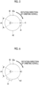
Fig. 5 is a schematic plan view showing a ring hole according to a second embodiment of the present disclosure. -
Fig. 6 is a diagram illustrating a modification example corresponding toFig. 5 . - Hereinafter, an embodiment of a compressor according to the present disclosure will be described with reference to the drawings.
- Hereinafter, a first embodiment of the present disclosure will be described with reference to
Figs. 1 to 4 . -
Fig. 1 is a vertical sectional view of an electric compressor 1 according to the present embodiment. - The electric compressor 1 according to the present embodiment is an inverter-integrated electric compressor in which an inverter (not shown) for driving a
motor 17 is integrally incorporated. - The electric compressor 1 includes a housing (casing) 2 that forms an outer shell, a
scroll compression mechanism 7 accommodated in thehousing 2, and themotor 17 that drives thescroll compression mechanism 7. - The
housing 2 has a cylindricalfirst housing 3 extending along a central axis, and asecond housing 4 that closes one end side (lower end side inFig. 1 ) of thefirst housing 3 in a direction of the central axis. - The
scroll compression mechanism 7 is incorporated in one end side of thehousing 2. Thescroll compression mechanism 7 has a pair offixed scroll 5 and an orbitingscroll 6. Thescroll compression mechanism 7 compresses a refrigerant gas. The high-pressure refrigerant gas compressed by thescroll compression mechanism 7 is discharged into adischarge chamber 10 through adischarge port 8. Thedischarge port 8 is formed at the center of thefixed scroll 5. The refrigerant gas discharged into thedischarge chamber 10 is discharged to the outside of the electric compressor 1 via a discharge port (not shown) provided in thehousing 2. - The
fixed scroll 5 is fixed to thesecond housing 4 by a fastener (not shown) such as a bolt. The orbitingscroll 6 is supported by a thrust bearing 12 to be able to orbit via arotation prevention mechanism 30. The details of therotation prevention mechanism 30 will be described later. The orbiting scroll 6 orbits with respect to thefixed scroll 5. Thefixed scroll 5 and the orbitingscroll 6 are made of, for example, aluminum. Raw materials of thefixed scroll 5 and theorbiting scroll 6 are not limited to aluminum. - The
fixed scroll 5 and theorbiting scroll 6 are engaged with each other to be meshed with each other. A compression chamber 14 is formed between thefixed scroll 5 and theorbiting scroll 6. In thescroll compression mechanism 7, the orbiting scroll 6 orbits (revolves) such that a volume of the compression chamber 14 decreases from the outer peripheral side toward the center side, and thus the refrigerant in the compression chamber 14 is compressed. - The
motor 17 is incorporated in the other end side of thecylindrical housing 2. Themotor 17 has astator 15 and arotor 16. Adrive shaft 18 is joined to therotor 16. Thedrive shaft 18 is rotatably supported by abearing 20 installed near a central portion inside thehousing 2 and abearing 21 installed near the other end portion inside thehousing 2. Acrank pin 19 is provided at one end of thedrive shaft 18. The central axes of thedrive shaft 18 and thecrank pin 19 are eccentric. Thecrank pin 19 is connected to the orbitingscroll 6. That is, thedrive shaft 18 connects themotor 17 to thescroll compression mechanism 7. Themotor 17 causes the orbitingscroll 6 to orbit via thedrive shaft 18. - A driven crank mechanism (not shown) is provided between the
crank pin 19 and the orbitingscroll 6. The driven crank mechanism performs the orbiting radius of the orbitingscroll 6 variable. Examples of the driven crank mechanism include a swing link type driven crank mechanism. - A suction port (not shown) for sucking a low-pressure refrigerant gas from a refrigerating cycle is provided on the other end side of the
housing 2. The refrigerant gas sucked from the suction port flows into aspace 24 between thefirst housing 3 and one end of themotor 17. The low-pressure refrigerant gas that has flowed into thespace 24 fills the inside of thehousing 2. Specifically, the low-pressure refrigerant gas that has flowed into thespace 24 flows to thescroll compression mechanism 7 side, is sucked into thescroll compression mechanism 7, and is compressed. A lubricant is contained in the refrigerant gas. The lubricant contained in the refrigerant gas is supplied to thescroll compression mechanism 7 and therotation prevention mechanism 30 together with the refrigerant gas to lubricate each mechanism. That is, the suction port has a function as a lubricant supply unit that supplies a lubricant to therotation prevention mechanism 30. - An
inverter accommodating portion 25 is provided on the other end side (upper end side inFig. 1 ) in a direction along the central axis of thehousing 2. The other end side of thefirst housing 3 is closed by theinverter accommodating portion 25. An inverter (not shown) that drives themotor 17 is accommodated inside theinverter accommodating portion 25. The inverter drives themotor 17 by converting DC power supplied from an external battery or the like into three-phase AC power having a required frequency and applying the AC power to themotor 17 via terminals (not shown). - Next, the
rotation prevention mechanism 30 will be described in detail. - The
rotation prevention mechanism 30 according to the present embodiment is a so-called pin ring type rotation prevention mechanism. Therotation prevention mechanism 30 prevents the rotation of theorbiting scroll 6. Therotation prevention mechanism 30 has a plurality of pin ring structures (rotation prevention structures) 31 (six in the present embodiment as an example) (refer toFig. 3 ). The plurality ofpin ring structures 31 are provided at equal intervals in the circumferential direction around the central axis of thedrive shaft 18 or theorbiting scroll 6. That is, in the present embodiment, since the sixpin ring structures 31 are provided, the sixpin ring structures 31 are provided at intervals of 60 degrees in the circumferential direction. - Since each of the plurality of
pin ring structures 31 has the same structure, in principle, onepin ring structure 31 will be described as a representative below. - As shown in
Figs. 1 and2 , thepin ring structure 31 includes a ring hole (recessed portion) 32 formed in theorbiting scroll 6, aring 33 accommodated in thering hole 32, and apin 34 that engages with an innerperipheral surface 33a of thering 33. - As shown in
Fig. 3 , the plurality of ring holes 32 are disposed to be arranged at predetermined intervals in anend plate 6a of theorbiting scroll 6. Specifically, the plurality of ring holes 32 are disposed to be arranged in the circumferential direction with the center point of theorbiting scroll 6 as the center. Thering hole 32 is formed on a surface (hereinafter, referred to as a "back surface 6b") of theend plate 6a of theorbiting scroll 6 opposite to the surface forming the compression chamber 14. Thering hole 32 is recessed to a predetermined depth from theback surface 6b of theorbiting scroll 6. Thering hole 32 is a bottomed recessed portion. Thering hole 32 has a perfect circular shape in a plan view. That is, an innerperipheral surface 32a of thering hole 32 is a cylindrical surface. - The
ring 33 is a cylindrical member having a predetermined thickness. A length of thering 33 in the direction of the central axis is substantially the same as the depth of thering hole 32. Thering 33 is disposed in thering hole 32. Thering 33 is disposed such that an outerperipheral surface 33b faces the innerperipheral surface 32a of thering hole 32. Thering 33 is made of, for example, high carbon chrome bearing steel (SUJ2). A raw material of thering 33 is not limited to the high carbon chrome bearing steel (SUJ2). In the present embodiment, an outer diameter of thering 33 is 13 mm or more and 15.5 mm or less. The value of the outer diameter of thering 33 is an example and is not limited to this value. - A gap G is formed between the inner
peripheral surface 32a of thering hole 32 and the outerperipheral surface 33b of thering 33. Regarding a length of the gap G, a length of the longest portion in a state in which a part of the outerperipheral surface 33b of thering 33 is in contact with the innerperipheral surface 32a of the ring hole 32 (hereinafter, simply a "length of the gap G") is 0.1 mm or more and 0.6 mm or less. That is, the outer diameter of thering 33 is smaller than the diameter of thering hole 32. Specifically, the outer diameter of thering 33 is smaller than the diameter of thering hole 32 by the length of the gap G. - A plurality of
pins 34 are disposed to correspond to therings 33 disposed in the respective ring holes 32. Specifically, the plurality ofpins 34 are disposed to be arranged at equal intervals in the circumferential direction with the central axis of thedrive shaft 18 as the center. As shown inFig. 1 , thepin 34 is fixed to thefirst housing 3. As shown inFig. 2 , thepin 34 is engaged with the innerperipheral surface 33a of thering 33. A tip of thepin 34 is separated from the bottom surface of thering hole 32. - The plurality of
pin ring structures 31 are disposed to sequentially receive a load in accordance with the orbiting motion of theorbiting scroll 6. That is, therotation prevention mechanism 30 sequentially passes the rotation prevention function between the plurality ofpin ring structures 31 in accordance with the orbiting motion of the orbiting scroll 6 (in other words, thepin ring structures 31 that function as therotation prevention mechanism 30 are switched), and thus the rotation of theorbiting scroll 6 is prevented. - The inner
peripheral surface 32a of thering hole 32 of eachpin ring structure 31 has a load region A1 over a predetermined angle range in which a load is received from thepin 34 in accordance with the orbiting motion of theorbiting scroll 6. Specifically, the load region A1 of thering hole 32 receives the load from thepin 34 via thering 33. As shown inFig. 3 , the load region A1 in each of the ring holes 32 is provided to be displaced by 60 degrees when theback surface 6b of theend plate 6a of theorbiting scroll 6 is viewed in a plan view. The load region A1 of eachring hole 32 is provided to form an arc at an angle θ (60 degrees in the present embodiment) when theback surface 6b of theend plate 6a of theorbiting scroll 6 is viewed in a plan view. - Next, a behavior of the
rotation prevention mechanism 30 will be described. - In the
rotation prevention mechanism 30, thepin 34 and thering 33 move relative to each other as theorbiting scroll 6 orbits, so that thepin 34 and thering 33 come into contact with each other, and the rotation of theorbiting scroll 6 is prevented due to the contact. In the present embodiment, thepin 34 fixed to thehousing 2 does not move, but thering 33 provided in theorbiting scroll 6 moves. - Next, a behavior of each
pin ring structure 31 will be described. When theorbiting scroll 6 orbits, first, onepin ring structure 31 among the sixpin ring structures 31 performs the rotation prevention function. Specifically, as thering 33 moves relative to thepin 34, the innerperipheral surface 33a of thering 33 provided in onepin ring structure 31 receives a load from thepin 34. As described above, the movement of thering hole 32 and thering 33 is restricted by thepin 34, and thus the rotation of theorbiting scroll 6 is prevented. Thering 33 moves along the outer peripheral surface of thepin 34 by a predetermined angle range (60 degrees in the present embodiment) while receiving a load. As a result, the load region A1 of thering hole 32 also receives the load via thering 33. When thering 33 and thering hole 32 move by a predetermined angle range, therotation prevention mechanism 30 switches thepin ring structures 31 that perform the rotation prevention function. Specifically, switching to thepin ring structure 31 located on the front side of theorbiting scroll 6 in the orbiting direction occurs. Also in thispin ring structure 31, the rotation of theorbiting scroll 6 is prevented in the same manner. As described above therotation prevention mechanism 30 prevents the rotation of theorbiting scroll 6 by repeatedly passing the rotation prevention function between the plurality ofpin ring structures 31. - According to the present embodiment, the following actions and effects are achieved.
- In the present embodiment, the length of the gap G formed between the
ring hole 32 and thering 33 is 0.1 mm or more and 0.6 mm or less. As a result, the lubricant supplied to therotation prevention mechanism 30 easily flows into the gap G. The lubricant that has flowed into the gap G alleviates an impact when thering hole 32 and thering 33 come into contact with each other. Therefore, noise caused by contact between thering hole 32 and thering 33 can be suppressed. - The noise caused by the contact between the
ring hole 32 and thering 33 includes, for example, noise generated when thepins 34 and therings 33 having the rotation prevention function are switched. - Next, a noise reduction effect of the
rotation prevention mechanism 30 according to the present embodiment will be described with reference to a graph ofFig. 4. Fig. 4 shows experimental results of investigating a relationship between the length of the gap G and the noise level. InFig. 4 , a horizontal axis represents the length of the gap G, and a vertical axis represents the noise level. - As shown in
Fig. 4 , in a case where the length of the gap G is less than 0.1 mm, the noise level is relatively high. It is considered that this is because, in a case where the length of the gap G is less than 0.1 mm, it is difficult for the lubricant to flow into the gap G. When the length of the gap G is 0.1 mm, the noise level is sharply reduced compared with the case where the gap G is less than 0.1 mm. This is because the length of the gap G is 0.1 mm, so that the lubricant suitably flows into the gap G. - It can be seen that, in a range in which the length of the gap G is 0.1 mm or more and less than 0.5 mm, the noise level decreases as the length of the gap G increases. When the length of the gap G is 0.5 mm or more, the noise level gradually increases. However, it can be seen that the noise level is sufficiently low when the length of the gap G is 0.6 mm or less.
- As described above, it can be understood from
Fig. 4 that noise can be suppressed in a case where the length of the gap G is 0.1 mm or more and 0.6 mm or less. - The graph in
Fig. 4 is suitably appropriate in a case where the outer diameter of thering 33 is 13 mm or more and 15.5 mm or less. - Next, a second embodiment of the present disclosure will be described with reference to
Fig. 5 . - The present embodiment is different from the first embodiment in that a storage portion is formed in the
ring hole 32. The present embodiment is the same as the first embodiment except that the storage portion is formed. Therefore, the same reference numerals are given to the same configurations, and detailed description thereof will be omitted. - As shown in
Fig. 5 , astorage portion 41 recessed outward in a radial direction is formed on an innerperipheral surface 42a of aring hole 42 according to the present embodiment. Thestorage portion 41 is formed in a rectangular shape in a plan view. Thestorage portion 41 is formed in a region other than the load region A1 (hereinafter, referred to as a "counterload region A2"). In the present embodiment, thestorage portion 41 is disposed to include a midpoint C in the circumferential direction of the counterload region A2. That is, thestorage portion 41 is provided at a position farthest from the load region A1. - The
storage portion 41 may be formed in all the ring holes 32 or may be formed in only some of the ring holes 32. - According to the present embodiment, the following actions and effects are achieved.
- In the present embodiment, the lubricant supplied to the
rotation prevention mechanism 30 is stored in thestorage portion 41. Since thestorage portion 41 is formed on the innerperipheral surface 42a of thering hole 42, in a case where an amount of lubricant held in the gap G between the innerperipheral surface 42a of thering hole 42 and the outerperipheral surface 33b of thering 33 is reduced, the lubricant stored in thestorage portion 41 is guided to the gap G. Therefore, the lubricant is more preferably held in the gap G. Therefore, noise caused by contact between thering hole 42 and thering 33 can be further suppressed. - In a case where the storage portion is formed in the load region A1, the
ring 33 may be deformed to be pushed into thestorage portion 41 due to the load from thepin 34 due to the orbiting motion of theorbiting scroll 6. Thestorage portion 41 may also be damaged by the load from thepin 34. On the other hand, in the present embodiment, thestorage portion 41 is formed in the counterload region A2. As a result, deformation of and damage to thering 33 can be suppressed. Damage to thestorage portion 41 due to the load from thepin 34 can be suppressed. - As in a
ring hole 52 shown inFig. 6 , on an innerperipheral surface 52a of thering hole 52, theentire storage portion 51 may be provided in front of the midpoint C in the circumferential direction of the counterload region A2 in the orbiting direction of theorbiting scroll 6. - The lubricant stored in the storage portion is guided to the load region A1 due to orbiting of the
orbiting scroll 6. Therefore, in the present modification example, a distance through which the lubricant travels is shorter than in a case where the storage portion is provided behind the midpoint C in the orbiting direction. Therefore, the lubricant can be suitably guided to the load region A1. Therefore, in the load region A1, the impact when thering hole 52 and thering 33 come into contact with each other can be suitably alleviated. Therefore, noise caused by contact between thering hole 52 and thering 33 can be more suitably suppressed. - The present disclosure is not limited to the invention according to each of the above embodiments, and can be modified as appropriate without departing from the concept thereof.
- For example, in each of the above embodiments, an example in which the electric compressor 1 is an inverter-integrated electric compressor has been described, but the present disclosure is not limited thereto. For example, the electric compressor 1 may be an electric compressor that does not include an inverter. The electric compressor 1 may be an electric compressor in which an inverter is separately provided.
- Shapes of the
storage portions - In each of the above embodiments, an example in which the
ring hole 32 is formed in theorbiting scroll 6 and thepin 34 is fixed to thefirst housing 3 has been described, but the present disclosure is not limited thereto. For example, thering hole 32 may be formed in thefirst housing 3, and thepin 34 may be fixed to theorbiting scroll 6. - The compressor described in the embodiment described above is understood as follows, for example.
- A compressor according to one aspect of the present disclosure includes a casing (2) that forms an outer shell, a fixed scroll (5) that is accommodated in the casing and fixed to the casing side, an orbiting scroll (6) that is meshed with the fixed scroll and orbits with respect to the fixed scroll, a rotation prevention mechanism (30) that prevents rotation of the orbiting scroll, and a lubricant supply unit that supplies a lubricant to the rotation prevention mechanism, in which the rotation prevention mechanism includes a recessed portion (32) formed on either the orbiting scroll side or the casing side, a ring (33) disposed in the recessed portion and having an outer peripheral surface (33b) facing an inner peripheral surface (32a) of the recessed portion, and a pin (34) provided on either the orbiting scroll side or the casing side and engaged with an inner peripheral surface (33a) of the ring, and a gap formed between the inner peripheral surface of the recessed portion and the outer peripheral surface of the ring is 0.1 mm or more and 0.6 mm or less.
- In the above configuration, the gap formed between the recessed portion and the ring is 0.1 mm or more and 0.6 mm or less. As a result, the lubricant supplied from the lubricant supply unit to the rotation prevention mechanism easily flows into the gap formed between the recessed portion and the ring. The lubricant that has flowed into the gap alleviates an impact when the recessed portion and the ring come into contact with each other. Therefore, noise caused by contact between the recessed portion and the ring can be suppressed.
- The noise caused by the contact between the recessed portion and the ring includes, for example, noise generated when, among a plurality of combinations of pins and rings, the rotation prevention function is passed from one combination of a pin and a ring to another combination of a pin and a ring (when the pins and the rings that perform the rotation prevention function are switched).
- In the compressor according to one aspect of the present disclosure, the outer diameter of the ring is 13 mm or more and 15.5 mm or less.
- In the compressor according to one aspect of the present disclosure, the recessed portion is provided with the storage portion (41, 51) recessed outward in a radial direction on the inner peripheral surface that is a cylindrical surface.
- In the above configuration, the lubricant supplied from the lubricant supply unit to the rotation prevention mechanism is stored in the oil storage portion. As a result, since the storage portion is formed on the inner peripheral surface of the recessed portion, in a case where an amount of lubricant held in the gap between the inner peripheral surface of the recessed portion and the outer peripheral surface of the ring is reduced, the lubricant stored in the storage portion is guided to the gap. Therefore, the lubricant is more preferably held in the gap between the inner peripheral surface of the recessed portion and the outer peripheral surface of the ring. Therefore, noise caused by contact between the recessed portion and the ring can be further suppressed.
- A compressor according to one aspect of the present disclosure includes a casing (2) that forms an outer shell, a fixed scroll (5) that is accommodated in the casing and fixed to the casing side, an orbiting scroll (6) that is meshed with the fixed scroll and orbits with respect to the fixed scroll, a rotation prevention mechanism (30) that prevents rotation of the orbiting scroll, and a lubricant supply unit that supplies a lubricant to the rotation prevention mechanism, in which the rotation prevention mechanism includes a recessed portion (32) formed on either the orbiting scroll side or the casing side, a ring (33) disposed in the recessed portion and having an outer peripheral surface (33b) facing an inner peripheral surface (32a) of the recessed portion, and a pin (34) provided on either the orbiting scroll side or the casing side and engaged with an inner peripheral surface (33a) of the ring, and the recessed portion is provided with a storage portion (41, 51) recessed outward in a radial direction on the inner peripheral surface that is a cylindrical surface.
- In the above configuration, the lubricant supplied from the lubricant supply unit to the rotation prevention mechanism is stored in the oil storage portion. As a result, since the storage portion is formed on the inner peripheral surface of the recessed portion, in a case where an amount of lubricant held in the gap between the inner peripheral surface of the recessed portion and the outer peripheral surface of the ring is reduced, the lubricant stored in the storage portion is guided to the gap. Therefore, the lubricant can be easily held in the gap between the inner peripheral surface of the recessed portion and the outer peripheral surface of the ring. The lubricant that has flowed into the gap alleviates an impact when the recessed portion and the ring come into contact with each other. Therefore, noise caused by contact between the recessed portion and the ring can be suppressed.
- In the compressor according to one aspect of the present disclosure, the rotation prevention mechanism has a plurality of rotation prevention structures that are a combination of the recessed portion, the ring, and the pin, the plurality of rotation prevention structures are disposed to sequentially receive a load in accordance with orbiting motion of the orbiting scroll, the inner peripheral surface of the recessed portion of each rotation prevention structure has a load region (A1) over a predetermined angle range in which the load is received from the pin in accordance with the orbiting motion of the orbiting scroll, and the storage portion is provided in a region (A2) other than the load region on the inner peripheral surface of the recessed portion.
- In a case where the storage portion is formed in the load region, the ring may be deformed to be pushed into the storage portion due to the load from the pin due to the orbiting motion of the orbiting scroll. The storage portion may be damaged by the load from the pin. On the other hand, in the above configuration, the storage portion is formed in a region other than the load region. As a result, deformation of and damage to the ring can be suppressed. Damage to the storage portion can be suppressed.
- In the compressor according to one aspect of the present disclosure, the storage portion is provided in front of the midpoint (C) in the circumferential direction of a region other than the load region in the orbiting direction of the orbiting scroll.
- The lubricant stored in the storage portion is guided to the load region in accordance with orbiting of the orbiting scroll. In the above configuration, the storage portion is provided in front of the midpoint in the circumferential direction of the region other than the load region in the orbiting direction of the orbiting scroll. As a result, a distance through which the lubricant travels is shorter than in a case where the storage portion is provided behind the midpoint in the orbiting direction. Therefore, the lubricant can be suitably guided to the load region. Therefore, in the load region, the impact when the recessed portion and the ring come into contact with each other can be suitably reduced. Therefore, noise caused by contact between the recessed portion and the ring can be suppressed.
-
- 1: Electric compressor (compressor)
- 2: Housing (casing)
- 3: First housing
- 4: Second housing
- 5: Fixed scroll
- 6: Orbiting scroll
- 6a: End plate
- 6b: Back surface
- 7: Scroll compression mechanism
- 8: Discharge port
- 10: Discharge chamber
- 12: Thrust bearing
- 14: Compression chamber
- 15: Stator
- 16: Rotor
- 17: Motor
- 18: Drive shaft
- 19: Crank pin
- 20: Bearing
- 21: Bearing
- 24: Space
- 25: Inverter accommodating portion
- 30: Rotation prevention mechanism
- 31: Pin ring structure (rotation prevention structure)
- 32: Ring hole (recessed portion)
- 32a: Inner peripheral surface
- 33: Ring
- 33a: Inner peripheral surface
- 33b: Outer peripheral surface
- 34: Pin
- 41: Storage portion
- 42: Ring hole
- 42a: Inner peripheral surface
- 51: Storage portion
- 52: Ring hole
- A1: Load region
- A2: Counterload region
- C: Midpoint
- G: Gap
Claims (6)
- A compressor comprising:a casing that forms an outer shell;a fixed scroll that is accommodated in the casing and fixed to a casing side;an orbiting scroll that is meshed with the fixed scroll and orbits with respect to the fixed scroll;a rotation prevention mechanism that prevents rotation of the orbiting scroll; anda lubricant supply unit that supplies a lubricant to the rotation prevention mechanism, whereinthe rotation prevention mechanism includes a recessed portion formed on either an orbiting scroll side or the casing side, a ring disposed in the recessed portion and having an outer peripheral surface facing an inner peripheral surface of the recessed portion, and a pin provided on either the orbiting scroll side or the casing side and engaged with an inner peripheral surface of the ring, anda gap formed between the inner peripheral surface of the recessed portion and the outer peripheral surface of the ring is 0.1 mm or more and 0.6 mm or less.
- The compressor according to claim 1, wherein an outer diameter of the ring is 13 mm or more and 15.5 mm or less.
- The compressor according to claim 1 or 2, wherein the recessed portion is provided with a storage portion recessed outward in a radial direction on the inner peripheral surface that is a cylindrical surface.
- A compressor comprising:a casing that forms an outer shell;a fixed scroll that is accommodated in the casing and fixed to a casing side;an orbiting scroll that is meshed with the fixed scroll and orbits with respect to the fixed scroll;a rotation prevention mechanism that prevents rotation of the orbiting scroll; anda lubricant supply unit that supplies a lubricant to the rotation prevention mechanism, whereinthe rotation prevention mechanism includes a recessed portion formed on either an orbiting scroll side or the casing side, a ring disposed in the recessed portion and having an outer peripheral surface facing an inner peripheral surface of the recessed portion, and a pin provided on either the orbiting scroll side or the casing side and engaged with an inner peripheral surface of the ring, andthe recessed portion is provided with a storage portion recessed outward in a radial direction on the inner peripheral surface that is a cylindrical surface.
- The compressor according to claim 3 or 4, whereinthe rotation prevention mechanism has a plurality of rotation prevention structures that are a combination of the recessed portion, the ring, and the pin,the plurality of rotation prevention structures are disposed to sequentially receive a load in accordance with an orbiting motion of the orbiting scroll,the inner peripheral surface of the recessed portion of each of the rotation prevention structures has a load region over a predetermined angle range in which the load is received from the pin in accordance with the orbiting motion of the orbiting scroll, andthe storage portion is provided in a region other than the load region on the inner peripheral surface of the recessed portion.
- The compressor according to claim 5, wherein the storage portion is provided in front of a midpoint in a circumferential direction of the region other than the load region in an orbiting direction of the orbiting scroll.
Applications Claiming Priority (2)
| Application Number | Priority Date | Filing Date | Title |
|---|---|---|---|
| JP2021008859A JP7749325B2 (en) | 2021-01-22 | 2021-01-22 | Compressor |
| PCT/JP2022/001384 WO2022158419A1 (en) | 2021-01-22 | 2022-01-17 | Compressor |
Publications (2)
| Publication Number | Publication Date |
|---|---|
| EP4265911A1 true EP4265911A1 (en) | 2023-10-25 |
| EP4265911A4 EP4265911A4 (en) | 2024-06-12 |
Family
ID=82549750
Family Applications (1)
| Application Number | Title | Priority Date | Filing Date |
|---|---|---|---|
| EP22742541.0A Pending EP4265911A4 (en) | 2021-01-22 | 2022-01-17 | COMPRESSOR |
Country Status (5)
| Country | Link |
|---|---|
| US (1) | US12385484B2 (en) |
| EP (1) | EP4265911A4 (en) |
| JP (1) | JP7749325B2 (en) |
| CN (2) | CN116724173A (en) |
| WO (1) | WO2022158419A1 (en) |
Families Citing this family (1)
| Publication number | Priority date | Publication date | Assignee | Title |
|---|---|---|---|---|
| JP7749325B2 (en) * | 2021-01-22 | 2025-10-06 | 三菱重工サーマルシステムズ株式会社 | Compressor |
Family Cites Families (11)
| Publication number | Priority date | Publication date | Assignee | Title |
|---|---|---|---|---|
| JP2001132670A (en) | 1999-11-09 | 2001-05-18 | Sanden Corp | Scroll compressor |
| JP4427354B2 (en) * | 2004-02-26 | 2010-03-03 | 三菱重工業株式会社 | Scroll compressor |
| JP2008180094A (en) * | 2007-01-23 | 2008-08-07 | Sanden Corp | Scroll-type fluid machine |
| JP5462994B2 (en) * | 2007-02-23 | 2014-04-02 | 三菱重工業株式会社 | Scroll compressor |
| JP6171601B2 (en) * | 2013-06-12 | 2017-08-02 | 株式会社豊田自動織機 | Rotation prevention mechanism of scroll compressor |
| DE102014113435A1 (en) * | 2014-09-17 | 2016-03-17 | Bitzer Kühlmaschinenbau Gmbh | compressor |
| FR3027972B1 (en) * | 2014-10-30 | 2019-09-20 | Valeo Japan Co., Ltd. | COMPRESSOR, IN PARTICULAR FOR MOTOR VEHICLE |
| KR102080622B1 (en) * | 2015-03-06 | 2020-02-25 | 한온시스템 주식회사 | Scroll compressor |
| KR102549777B1 (en) * | 2016-12-21 | 2023-06-30 | 삼성전자주식회사 | Scroll compressor |
| JP6750548B2 (en) * | 2017-03-30 | 2020-09-02 | 株式会社豊田自動織機 | Scroll compressor |
| JP7749325B2 (en) * | 2021-01-22 | 2025-10-06 | 三菱重工サーマルシステムズ株式会社 | Compressor |
-
2021
- 2021-01-22 JP JP2021008859A patent/JP7749325B2/en active Active
-
2022
- 2022-01-17 WO PCT/JP2022/001384 patent/WO2022158419A1/en not_active Ceased
- 2022-01-17 US US18/272,454 patent/US12385484B2/en active Active
- 2022-01-17 EP EP22742541.0A patent/EP4265911A4/en active Pending
- 2022-01-17 CN CN202280010368.9A patent/CN116724173A/en active Pending
- 2022-01-20 CN CN202220154438.5U patent/CN217107422U/en active Active
Also Published As
| Publication number | Publication date |
|---|---|
| EP4265911A4 (en) | 2024-06-12 |
| WO2022158419A1 (en) | 2022-07-28 |
| US12385484B2 (en) | 2025-08-12 |
| CN116724173A (en) | 2023-09-08 |
| JP7749325B2 (en) | 2025-10-06 |
| JP2022112858A (en) | 2022-08-03 |
| US20240068472A1 (en) | 2024-02-29 |
| CN217107422U (en) | 2022-08-02 |
Similar Documents
| Publication | Publication Date | Title |
|---|---|---|
| EP2538083B1 (en) | Scroll compressor | |
| CN105556125B (en) | Electric scroll compressor | |
| EP2913531B1 (en) | Scroll compressor with balance weight | |
| US9784272B2 (en) | Scroll-type fluid machine | |
| EP2426359A1 (en) | Scroll compressor | |
| EP3584443B1 (en) | Compressor | |
| US12385484B2 (en) | Compressor | |
| EP2497954B1 (en) | Scroll compressor | |
| EP2194274B1 (en) | Scroll compressor | |
| EP3564531B1 (en) | Motor-operated scroll compressor | |
| US11976653B2 (en) | Scroll compressor with suppressed reduction of rotational moment | |
| KR20200132421A (en) | Scroll-type compressor | |
| US7273361B2 (en) | Coupling structure of eccentric bush of scroll compressor | |
| EP3572670B1 (en) | Scroll compressor | |
| US6193489B1 (en) | Shaft assembly mechanism for scroll compressor | |
| JP2025066427A (en) | Compressor | |
| US20260074579A1 (en) | Electric compressor | |
| EP4600495A1 (en) | Scroll compressor | |
| US8939741B2 (en) | Scroll compressor | |
| JP2026072255A (en) | Scroll compressor | |
| KR20250028011A (en) | Scroll compressor | |
| JP3913072B2 (en) | Scroll compressor | |
| JP2001221176A (en) | Scroll fluid machine | |
| JP2013181487A (en) | Scroll compressor | |
| WO2018021058A1 (en) | Scroll compressor |
Legal Events
| Date | Code | Title | Description |
|---|---|---|---|
| STAA | Information on the status of an ep patent application or granted ep patent |
Free format text: STATUS: THE INTERNATIONAL PUBLICATION HAS BEEN MADE |
|
| PUAI | Public reference made under article 153(3) epc to a published international application that has entered the european phase |
Free format text: ORIGINAL CODE: 0009012 |
|
| STAA | Information on the status of an ep patent application or granted ep patent |
Free format text: STATUS: REQUEST FOR EXAMINATION WAS MADE |
|
| 17P | Request for examination filed |
Effective date: 20230719 |
|
| AK | Designated contracting states |
Kind code of ref document: A1 Designated state(s): AL AT BE BG CH CY CZ DE DK EE ES FI FR GB GR HR HU IE IS IT LI LT LU LV MC MK MT NL NO PL PT RO RS SE SI SK SM TR |
|
| DAV | Request for validation of the european patent (deleted) | ||
| DAX | Request for extension of the european patent (deleted) | ||
| A4 | Supplementary search report drawn up and despatched |
Effective date: 20240513 |
|
| RIC1 | Information provided on ipc code assigned before grant |
Ipc: F01C 17/06 20060101ALI20240506BHEP Ipc: F04C 23/00 20060101ALI20240506BHEP Ipc: F04C 29/00 20060101ALI20240506BHEP Ipc: F04C 29/06 20060101ALI20240506BHEP Ipc: F04C 29/02 20060101ALI20240506BHEP Ipc: F04C 18/02 20060101AFI20240506BHEP |
|
| STAA | Information on the status of an ep patent application or granted ep patent |
Free format text: STATUS: EXAMINATION IS IN PROGRESS |
|
| 17Q | First examination report despatched |
Effective date: 20250623 |