EP4265895A1 - Waste heat capture using tail cone of a gas turbine engine - Google Patents
Waste heat capture using tail cone of a gas turbine engine Download PDFInfo
- Publication number
- EP4265895A1 EP4265895A1 EP23168276.6A EP23168276A EP4265895A1 EP 4265895 A1 EP4265895 A1 EP 4265895A1 EP 23168276 A EP23168276 A EP 23168276A EP 4265895 A1 EP4265895 A1 EP 4265895A1
- Authority
- EP
- European Patent Office
- Prior art keywords
- thermoelectric material
- air
- tail cone
- component
- turbine engine
- Prior art date
- Legal status (The legal status is an assumption and is not a legal conclusion. Google has not performed a legal analysis and makes no representation as to the accuracy of the status listed.)
- Granted
Links
Images



Classifications
-
- F—MECHANICAL ENGINEERING; LIGHTING; HEATING; WEAPONS; BLASTING
- F02—COMBUSTION ENGINES; HOT-GAS OR COMBUSTION-PRODUCT ENGINE PLANTS
- F02K—JET-PROPULSION PLANTS
- F02K1/00—Plants characterised by the form or arrangement of the jet pipe or nozzle; Jet pipes or nozzles peculiar thereto
- F02K1/04—Mounting of an exhaust cone in the jet pipe
-
- H—ELECTRICITY
- H10—SEMICONDUCTOR DEVICES; ELECTRIC SOLID-STATE DEVICES NOT OTHERWISE PROVIDED FOR
- H10N—ELECTRIC SOLID-STATE DEVICES NOT OTHERWISE PROVIDED FOR
- H10N10/00—Thermoelectric devices comprising a junction of dissimilar materials, i.e. devices exhibiting Seebeck or Peltier effects
- H10N10/10—Thermoelectric devices comprising a junction of dissimilar materials, i.e. devices exhibiting Seebeck or Peltier effects operating with only the Peltier or Seebeck effects
- H10N10/13—Thermoelectric devices comprising a junction of dissimilar materials, i.e. devices exhibiting Seebeck or Peltier effects operating with only the Peltier or Seebeck effects characterised by the heat-exchanging means at the junction
-
- F—MECHANICAL ENGINEERING; LIGHTING; HEATING; WEAPONS; BLASTING
- F01—MACHINES OR ENGINES IN GENERAL; ENGINE PLANTS IN GENERAL; STEAM ENGINES
- F01D—NON-POSITIVE DISPLACEMENT MACHINES OR ENGINES, e.g. STEAM TURBINES
- F01D15/00—Adaptations of machines or engines for special use; Combinations of engines with devices driven thereby
- F01D15/10—Adaptations for driving, or combinations with, electric generators
-
- F—MECHANICAL ENGINEERING; LIGHTING; HEATING; WEAPONS; BLASTING
- F01—MACHINES OR ENGINES IN GENERAL; ENGINE PLANTS IN GENERAL; STEAM ENGINES
- F01D—NON-POSITIVE DISPLACEMENT MACHINES OR ENGINES, e.g. STEAM TURBINES
- F01D25/00—Component parts, details, or accessories, not provided for in, or of interest apart from, other groups
- F01D25/08—Cooling; Heating; Heat-insulation
- F01D25/12—Cooling
-
- F—MECHANICAL ENGINEERING; LIGHTING; HEATING; WEAPONS; BLASTING
- F02—COMBUSTION ENGINES; HOT-GAS OR COMBUSTION-PRODUCT ENGINE PLANTS
- F02C—GAS-TURBINE PLANTS; AIR INTAKES FOR JET-PROPULSION PLANTS; CONTROLLING FUEL SUPPLY IN AIR-BREATHING JET-PROPULSION PLANTS
- F02C6/00—Plural gas-turbine plants; Combinations of gas-turbine plants with other apparatus; Adaptations of gas-turbine plants for special use
- F02C6/18—Plural gas-turbine plants; Combinations of gas-turbine plants with other apparatus; Adaptations of gas-turbine plants for special use using the waste heat of gas-turbine plants outside the plants themselves, e.g. gas-turbine power heat plants
-
- F—MECHANICAL ENGINEERING; LIGHTING; HEATING; WEAPONS; BLASTING
- F02—COMBUSTION ENGINES; HOT-GAS OR COMBUSTION-PRODUCT ENGINE PLANTS
- F02C—GAS-TURBINE PLANTS; AIR INTAKES FOR JET-PROPULSION PLANTS; CONTROLLING FUEL SUPPLY IN AIR-BREATHING JET-PROPULSION PLANTS
- F02C7/00—Features, components parts, details or accessories, not provided for in, or of interest apart form groups F02C1/00 - F02C6/00; Air intakes for jet-propulsion plants
- F02C7/12—Cooling of plants
-
- F—MECHANICAL ENGINEERING; LIGHTING; HEATING; WEAPONS; BLASTING
- F02—COMBUSTION ENGINES; HOT-GAS OR COMBUSTION-PRODUCT ENGINE PLANTS
- F02K—JET-PROPULSION PLANTS
- F02K1/00—Plants characterised by the form or arrangement of the jet pipe or nozzle; Jet pipes or nozzles peculiar thereto
- F02K1/78—Other construction of jet pipes
- F02K1/82—Jet pipe walls, e.g. liners
- F02K1/822—Heat insulating structures or liners, cooling arrangements, e.g. post combustion liners; Infrared radiation suppressors
-
- F—MECHANICAL ENGINEERING; LIGHTING; HEATING; WEAPONS; BLASTING
- F02—COMBUSTION ENGINES; HOT-GAS OR COMBUSTION-PRODUCT ENGINE PLANTS
- F02K—JET-PROPULSION PLANTS
- F02K3/00—Plants including a gas turbine driving a compressor or a ducted fan
- F02K3/02—Plants including a gas turbine driving a compressor or a ducted fan in which part of the working fluid by-passes the turbine and combustion chamber
- F02K3/04—Plants including a gas turbine driving a compressor or a ducted fan in which part of the working fluid by-passes the turbine and combustion chamber the plant including ducted fans, i.e. fans with high volume, low pressure outputs, for augmenting the jet thrust, e.g. of double-flow type
- F02K3/06—Plants including a gas turbine driving a compressor or a ducted fan in which part of the working fluid by-passes the turbine and combustion chamber the plant including ducted fans, i.e. fans with high volume, low pressure outputs, for augmenting the jet thrust, e.g. of double-flow type with front fan
-
- F—MECHANICAL ENGINEERING; LIGHTING; HEATING; WEAPONS; BLASTING
- F05—INDEXING SCHEMES RELATING TO ENGINES OR PUMPS IN VARIOUS SUBCLASSES OF CLASSES F01-F04
- F05D—INDEXING SCHEME FOR ASPECTS RELATING TO NON-POSITIVE-DISPLACEMENT MACHINES OR ENGINES, GAS-TURBINES OR JET-PROPULSION PLANTS
- F05D2220/00—Application
- F05D2220/60—Application making use of surplus or waste energy
-
- F—MECHANICAL ENGINEERING; LIGHTING; HEATING; WEAPONS; BLASTING
- F05—INDEXING SCHEMES RELATING TO ENGINES OR PUMPS IN VARIOUS SUBCLASSES OF CLASSES F01-F04
- F05D—INDEXING SCHEME FOR ASPECTS RELATING TO NON-POSITIVE-DISPLACEMENT MACHINES OR ENGINES, GAS-TURBINES OR JET-PROPULSION PLANTS
- F05D2220/00—Application
- F05D2220/70—Application in combination with
- F05D2220/76—Application in combination with an electrical generator
-
- F—MECHANICAL ENGINEERING; LIGHTING; HEATING; WEAPONS; BLASTING
- F05—INDEXING SCHEMES RELATING TO ENGINES OR PUMPS IN VARIOUS SUBCLASSES OF CLASSES F01-F04
- F05D—INDEXING SCHEME FOR ASPECTS RELATING TO NON-POSITIVE-DISPLACEMENT MACHINES OR ENGINES, GAS-TURBINES OR JET-PROPULSION PLANTS
- F05D2260/00—Function
- F05D2260/20—Heat transfer, e.g. cooling
-
- F—MECHANICAL ENGINEERING; LIGHTING; HEATING; WEAPONS; BLASTING
- F05—INDEXING SCHEMES RELATING TO ENGINES OR PUMPS IN VARIOUS SUBCLASSES OF CLASSES F01-F04
- F05D—INDEXING SCHEME FOR ASPECTS RELATING TO NON-POSITIVE-DISPLACEMENT MACHINES OR ENGINES, GAS-TURBINES OR JET-PROPULSION PLANTS
- F05D2260/00—Function
- F05D2260/20—Heat transfer, e.g. cooling
- F05D2260/231—Preventing heat transfer
-
- H—ELECTRICITY
- H10—SEMICONDUCTOR DEVICES; ELECTRIC SOLID-STATE DEVICES NOT OTHERWISE PROVIDED FOR
- H10N—ELECTRIC SOLID-STATE DEVICES NOT OTHERWISE PROVIDED FOR
- H10N10/00—Thermoelectric devices comprising a junction of dissimilar materials, i.e. devices exhibiting Seebeck or Peltier effects
- H10N10/10—Thermoelectric devices comprising a junction of dissimilar materials, i.e. devices exhibiting Seebeck or Peltier effects operating with only the Peltier or Seebeck effects
- H10N10/17—Thermoelectric devices comprising a junction of dissimilar materials, i.e. devices exhibiting Seebeck or Peltier effects operating with only the Peltier or Seebeck effects characterised by the structure or configuration of the cell or thermocouple forming the device
Definitions
- the present invention generally relates to waste heat capture, and more specifically to, waste heat capture using tail cone of a gas turbine engine.
- An aircraft gas turbine engine of the conventional turbofan type generally includes a forward bypass fan and a low pressure compressor, a middle core engine, and an aft low pressure turbine all located along a common longitudinal axis. Air flows into the engine at an inner diameter and an outer diameter of the engine. Air entering through the outer diameter of the engine exits the rear of the engine at the outer diameter as a relatively low temperature gas stream after flowing through the bypass fan. Airflow entering the inner diameter of the engine enters a high pressure compressor driven by a high pressure turbine to compress the air to a high pressure. This high pressure air is then mixed with fuel in a combustor and ignited to form a relatively high temperature gas stream.
- the high temperature gas stream flows axially aft to rotatably drive the high pressure turbine which rotatably drives the high pressure compressor through the high pressure shaft.
- the high temperature gas stream leaving the high pressure turbine is expanded through the low pressure turbine which rotatably drives the bypass fan and low pressure compressor through a low pressure shaft.
- the high temperature gas stream exits the rear of the engine at the inner diameter from the low pressure turbine and flows over a tailcone.
- the tailcone is made of titanium or other metal to withstand the elevated temperatures of the high temperature gas stream.
- Embodiments of the present invention are directed to a turbine engine.
- a non-limiting example of the turbine engine includes a tail cone, a fan that drives air along a bypass flow path in a bypass duct and a core flow path in a compression duct.
- the core flow path flows around an exterior surface of the tail cone.
- the engine also includes an air scoop connected to the tail cone, the air scoop configured to direct air from the bypass duct to an interior compartment of the tail cone and a thermoelectric material connected to an interior surface of the tail cone.
- the interior compartment of the tail cone is on a first side of the thermoelectric material, wherein the bypass flow path comprises air having a first temperature range, and wherein the core flow path is confirmed to receive air having a second temperature range, wherein the second temperature range is an order of magnitude higher than the first temperature range.
- thermoelectric material a temperature differential is created in the thermoelectric material based on a temperature difference between the bypass flow path on the first side of the thermoelectric material and the core flow path on the exterior surface of the tail cone.
- the temperature differential causes an electrical voltage to be generated in the thermoelectric material.
- the engine can further include: an electrical component connected to the thermoelectric material.
- thermoelectric material is conformally connected to the interior of the tail cone.
- the air scoop comprises titanium.
- the turbine can further include: an insulation layer between the exterior surface of the tail cone and the thermoelectric material.
- the insulation layer comprises an electrically insulative and thermally conducting material.
- the tail cone comprises an exit port for the interior compartment.
- thermoelectric material comprises n-doped and p-doped semiconductors.
- a waste heat capture system that includes an air scoop connected to a first component, the air scoop configured to direct air from a first duct to an interior compartment of the first component, a second duct along an exterior of the first component; and a thermoelectric material connected to an interior surface of the first component.
- the interior compartment of the first component is on a first side of the thermoelectric material and the exterior of the first component is on a second side of the thermoelectric material.
- the first duct is configured to receive air having a first temperature range
- the second duct is configured to receive air having a second temperature range, wherein the second temperature range is an order of magnitude higher than the first temperature range.
- thermoelectric material a temperature differential is created in the thermoelectric material based on a temperature difference between the air in the first duct on the first side of the thermoelectric material and the air in the second duct on the exterior surface of the first component.
- the temperature differential causes an electrical voltage to be generated in the thermoelectric material.
- system can further includes an electrical component connected to the thermoelectric material.
- thermoelectric material is conformally connected to the interior of the first component.
- the first component comprises a tail cone in a turbine engine.
- the air scoop comprises titanium.
- system can further include an insulation layer between the exterior surface of the tail cone and the thermoelectric material.
- the first component comprises an exit port for the interior compartment.
- thermoelectric material comprises n-doped and p-doped semiconductors.
- FIG. 1 illustrates an example of a commercial aircraft 10 having aircraft engines 20 that may embody aspects of the teachings of this disclosure.
- the aircraft 10 includes two wings 22 that each include one or more slats 24 and one or more flaps 26.
- the aircraft further includes ailerons 27, spoilers 28, horizontal stabilizer trim tabs 29, rudder 30 and horizontal stabilizer 31.
- control surface used herein includes but is not limited to either a slat or a flap or any of the above described. It will be understood that the slats 24 and/or the flaps 26 can include one or more slat/flap panels that move together.
- the aircraft 10 also includes a waste heat capture system 220 (described in greater detail in FIG. 3 ) which allows for utilization of waste heat for electrical power on board the aircraft 10.
- MEA fully electric aircraft
- functionality that has previously been achieved utilizing a pneumatic and/or hydraulic system can now be replaced fully or partially by an electric system.
- a few examples where the previous systems can be substituted for an electric system include, but are not limited to, flight controls, fuel pumps, oil pumps, cooling pumps, landing system, cargo and air management systems, and the like.
- These electric systems require power supplied from various generators and/or battery systems on the aircraft. Since these power systems are a necessity, new ways of generating power on board the aircraft are required.
- FIG. 2 is a perspective view of a ducted fan gas turbine engine with a waste heat capture system according to one or more embodiments.
- the gas turbine engine 200 includes, in axial flow series, a fan 232, intermediate pressure compressor 234, a high pressure compressor 236, combustion equipment 238, high, intermediate, and low pressure turbines 240, 242, and 244, respectively and an exhaust nozzle 246. Air can be accelerated by the fan 232 to produce two flows of air, the larger airflow (bypass air cooling air flow) 206 can be exhausted from the engine 200 to provide propulsive thrust through a bypass duct.
- the smaller airflow (low pressure exhaust flow 208) is directed into the compression duct which flows to an intermediate pressure compressor 234 where it can be compressed and then into the high pressure compressor 236 where further compression can take place.
- the compressed air then can be mixed with fuel in the combustion equipment 238 and the mixture combusted.
- the resultant combustion products then can expand through the high, intermediate, and low pressure turbines 240, 242, and 244 respectively before being exhausted to the atmosphere through the exhaust nozzle 246 to provide additional propulsive thrust.
- the two airflows 206, 208 have a much different temperature range due to the combustion of the compressed air with fuel taking place in the second airflow 208.
- the first airflow (bypass airflow) 206 has a typical ground temperature of 40-60 C and a typical cruising temperature of 30-50 C.
- the second airflow (low pressure turbine exhaust) 208 has a typical ground temperature of 540-575 C and a typical cruising temperature of 640 - 670 C.
- the turbine engine 200 includes a waste heat capture system 220 that utilizes thermoelectric material to create a voltage.
- Thermoelectric materials have the capability of energy conversion between heat and electricity and vice-versa.
- the thermoelectric materials are used in a thermoelectric generator (TEG) to generate power on an aircraft.
- TEG thermoelectric generator
- a TEG is a solid state device that converts heat flux (temperature differences) directly into electrical energy through the Seebeck effect.
- the turbine engine 200 includes a tail cone 210.
- the tail cone 210 is used to make the exhaust air divergent which reduces the flow velocity of the exhaust air and increase thrust due to the smoothening of the air flow out of the exhaust nozzle 246.
- the tail cone 210 is typically hollow and constructed using a material such as titanium or other metal capable of withstanding an elevated temperature. As mentioned above, for a TEG to operate, there needs to be a temperature differential (heat flux) to convert heat into an electrical energy through the Seebeck effect.
- the turbine engine 200 includes a scoop 202 configured to direct air from the bypass air flow 206 into the tail cone 210 (to be shown in more detail in FIG. 3 ). Given the differences in temperatures between the bypass airflow 206 and the turbine exhaust airflow 208, a TEG is able to operate and produce a voltage.
- FIG. 3 depicts a waste heat capture system using a thermoelectric generator according one or more embodiments.
- the waste heat capture system 220 includes a tail cone 210 of the turbine engine 200 (from FIG. 2 ).
- the tail cone 210 is typically made of titanium or another metal capable of withstanding high temperatures.
- the air scoop 202 (from FIG. 2 ) is configured to redirect the bypass air flow 206 into an interior compartment 304 of the tail cone 210 and through an exit port 306.
- the scoop 202 is a titanium fairing that can be curved to better redirect the cooler air flow from the bypass airflow 206 into the tail cone 210 and interior compartment 304.
- this bypass airflow 206 has a temperature range of 30 - 60 C depending on the location of the aircraft.
- the higher temperature air flow 208 (low pressure turbine exhaust flow) continues to flow around the exterior of the tail cone 210.
- the waste heat capture system 220 includes a thermoelectric material 302 that is conformally connected to an interior surface of the tail cone 210 housing. This configuration has the effect of a high temperature air flow (208) on one side of the thermoelectric material 302 and a lower temperature air flow 206 on an opposite side of the thermoelectric material 302.
- the thermoelectric materials 302 include materials of different Seebeck coefficients (e.g., p-doped and n-doped semiconductors).
- thermoelectric material 302 experiences a temperature gradient across two junctions (cold junction and hot junction).
- the thermoelectric material generates a potential difference corresponding to the temperature gradient.
- Terminal voltage and output power are a function of the temperature difference across the junctions.
- the Peltier cells can be connected in series or parallel configurations to make the thermoelectric material 302 match the required voltage and current output or the heat transfer across the junctions.
- this thermoelectric material 302 can be connected to electrical components for usage as a power source/generator called a thermoelectric generator (TEG).
- TOG thermoelectric generator
- the TEG also cools the housing of the tail cone 210 through thermoelectric cooling (Peltier effect).
- the electrical energy generated by the TEG can be utilized for multiple applications including, but not limited to, powering up on board sensors, feeding back to a DC bus, and the like. Additionally, power converters can be used to boost the voltage to higher voltage and transfer on higher voltage bus.
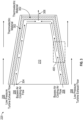
- FIG. 4 depicts a side view of a cross section of the waste heat capture system according to one or more embodiments.
- the cross section 400 includes the tail cone housing 404 having a TEG 402 that includes the thermoelectric material. These TEG 402 can be connected to an electrical component to generate a voltage. Above the TEG 402 and above the tail cone housing 404 is the airflow 208 from the exhaust air of the turbine engine. The redirected cooler airflow 206 is under the TEG 402 thus creating a temperature gradient for use by the TEG 402 to generate a voltage.
- the tail cone housing 404 can include an electrically insulating and thermally conducting material/layers 406.
- the electrical insulation 406 can be a material such as 30 mil Nomex or Kapton or combination, capable of withstanding high temperatures. As described above, the high temperature turbine exhaust airflow 208 along with the bypass air flow 206 creates a temperature gradient for the TEG 402 to generate a voltage.
Landscapes
- Engineering & Computer Science (AREA)
- Mechanical Engineering (AREA)
- General Engineering & Computer Science (AREA)
- Chemical & Material Sciences (AREA)
- Combustion & Propulsion (AREA)
- Structures Of Non-Positive Displacement Pumps (AREA)
- Engine Equipment That Uses Special Cycles (AREA)
Abstract
Description
- The present invention generally relates to waste heat capture, and more specifically to, waste heat capture using tail cone of a gas turbine engine.
- An aircraft gas turbine engine of the conventional turbofan type generally includes a forward bypass fan and a low pressure compressor, a middle core engine, and an aft low pressure turbine all located along a common longitudinal axis. Air flows into the engine at an inner diameter and an outer diameter of the engine. Air entering through the outer diameter of the engine exits the rear of the engine at the outer diameter as a relatively low temperature gas stream after flowing through the bypass fan. Airflow entering the inner diameter of the engine enters a high pressure compressor driven by a high pressure turbine to compress the air to a high pressure. This high pressure air is then mixed with fuel in a combustor and ignited to form a relatively high temperature gas stream. The high temperature gas stream flows axially aft to rotatably drive the high pressure turbine which rotatably drives the high pressure compressor through the high pressure shaft. The high temperature gas stream leaving the high pressure turbine is expanded through the low pressure turbine which rotatably drives the bypass fan and low pressure compressor through a low pressure shaft. The high temperature gas stream exits the rear of the engine at the inner diameter from the low pressure turbine and flows over a tailcone. The tailcone is made of titanium or other metal to withstand the elevated temperatures of the high temperature gas stream.
- Embodiments of the present invention are directed to a turbine engine. A non-limiting example of the turbine engine includes a tail cone, a fan that drives air along a bypass flow path in a bypass duct and a core flow path in a compression duct. The core flow path flows around an exterior surface of the tail cone. The engine also includes an air scoop connected to the tail cone, the air scoop configured to direct air from the bypass duct to an interior compartment of the tail cone and a thermoelectric material connected to an interior surface of the tail cone. The interior compartment of the tail cone is on a first side of the thermoelectric material, wherein the bypass flow path comprises air having a first temperature range, and wherein the core flow path is confirmed to receive air having a second temperature range, wherein the second temperature range is an order of magnitude higher than the first temperature range.
- In addition to one or more of the features described above, or as an alternative to any of the foregoing embodiments, a temperature differential is created in the thermoelectric material based on a temperature difference between the bypass flow path on the first side of the thermoelectric material and the core flow path on the exterior surface of the tail cone.
- In addition to one or more of the features described above, or as an alternative to any of the foregoing embodiments, the temperature differential causes an electrical voltage to be generated in the thermoelectric material.
- In addition to one or more of the features described above, or as an alternative to any of the foregoing embodiments, the engine can further include: an electrical component connected to the thermoelectric material.
- In addition to one or more of the features described above, or as an alternative to any of the foregoing embodiments, the thermoelectric material is conformally connected to the interior of the tail cone.
- In addition to one or more of the features described above, or as an alternative to any of the foregoing embodiments, the air scoop comprises titanium.
- In addition to one or more of the features described above, or as an alternative to any of the foregoing embodiments, the turbine can further include: an insulation layer between the exterior surface of the tail cone and the thermoelectric material.
- In addition to one or more of the features described above, or as an alternative to any of the foregoing embodiments, the insulation layer comprises an electrically insulative and thermally conducting material.
- In addition to one or more of the features described above, or as an alternative to any of the foregoing embodiments, the tail cone comprises an exit port for the interior compartment.
- In addition to one or more of the features described above, or as an alternative to any of the foregoing embodiments, the thermoelectric material comprises n-doped and p-doped semiconductors.
- Also disclosed is a waste heat capture system that includes an air scoop connected to a first component, the air scoop configured to direct air from a first duct to an interior compartment of the first component, a second duct along an exterior of the first component; and a thermoelectric material connected to an interior surface of the first component. The interior compartment of the first component is on a first side of the thermoelectric material and the exterior of the first component is on a second side of the thermoelectric material. The first duct is configured to receive air having a first temperature range, and wherein the second duct is configured to receive air having a second temperature range, wherein the second temperature range is an order of magnitude higher than the first temperature range.
- In addition to one or more of the features described above, or as an alternative to any of the foregoing system embodiments, a temperature differential is created in the thermoelectric material based on a temperature difference between the air in the first duct on the first side of the thermoelectric material and the air in the second duct on the exterior surface of the first component.
- In addition to one or more of the features described above, or as an alternative to any of the foregoing system embodiments, the temperature differential causes an electrical voltage to be generated in the thermoelectric material.
- In addition to one or more of the features described above, or as an alternative to any of the foregoing system embodiments, the system can further includes an electrical component connected to the thermoelectric material.
- In addition to one or more of the features described above, or as an alternative to any of the foregoing system embodiments, the thermoelectric material is conformally connected to the interior of the first component.
- In addition to one or more of the features described above, or as an alternative to any of the foregoing system embodiments, the first component comprises a tail cone in a turbine engine.
- In addition to one or more of the features described above, or as an alternative to any of the foregoing system embodiments, the air scoop comprises titanium.
- In addition to one or more of the features described above, or as an alternative to any of the foregoing system embodiments, the system can further include an insulation layer between the exterior surface of the tail cone and the thermoelectric material.
- In addition to one or more of the features described above, or as an alternative to any of the foregoing system embodiments, the first component comprises an exit port for the interior compartment.
- In addition to one or more of the features described above, or as an alternative to any of the foregoing system embodiments, the thermoelectric material comprises n-doped and p-doped semiconductors.
- Additional technical features and benefits are realized through the techniques of the present invention. Embodiments and aspects of the invention are described in detail herein and are considered a part of the claimed subject matter. For a better understanding, refer to the detailed description and to the drawings.
- The specifics of the exclusive rights described herein are particularly pointed out and distinctly claimed in the claims at the conclusion of the specification. The foregoing and other features and advantages of the embodiments of the invention are apparent from the following detailed description taken in conjunction with the accompanying drawings in which:
-
FIG. 1 is a perspective view of an aircraft that may incorporate embodiments of the present disclosure; -
FIG. 2 is a perspective view of a ducted fan gas turbine engine with a waste heat capture system according to one or more embodiments; -
FIG. 3 depicts a waste heat capture system using a thermoelectric generator according one or more embodiments; and -
FIG. 4 depicts a side view of a cross section of the waste heat capture system according to one or more embodiments. - The diagrams depicted herein are illustrative. There can be many variations to the diagram or the operations described therein without departing from the spirit of the invention. For instance, the actions can be performed in a differing order or actions can be added, deleted or modified. Also, the term "coupled" and variations thereof describes having a communications path between two elements and does not imply a direct connection between the elements with no intervening elements/connections between them. All of these variations are considered a part of the specification.
-
FIG. 1 illustrates an example of acommercial aircraft 10 havingaircraft engines 20 that may embody aspects of the teachings of this disclosure. Theaircraft 10 includes twowings 22 that each include one ormore slats 24 and one ormore flaps 26. The aircraft further includesailerons 27,spoilers 28, horizontalstabilizer trim tabs 29,rudder 30 andhorizontal stabilizer 31. The term "control surface" used herein includes but is not limited to either a slat or a flap or any of the above described. It will be understood that theslats 24 and/or theflaps 26 can include one or more slat/flap panels that move together. Theaircraft 10 also includes a waste heat capture system 220 (described in greater detail inFIG. 3 ) which allows for utilization of waste heat for electrical power on board theaircraft 10. - Turning now to an overview of technologies that are more specifically relevant to aspects of the disclosure, the concept of a fully electric aircraft (FEA) has been proposed in the past. However, to achieve a FEA, the technological space must first contend with a more electric aircraft (MEA). In the MEA, functionality that has previously been achieved utilizing a pneumatic and/or hydraulic system can now be replaced fully or partially by an electric system. A few examples where the previous systems can be substituted for an electric system include, but are not limited to, flight controls, fuel pumps, oil pumps, cooling pumps, landing system, cargo and air management systems, and the like. These electric systems require power supplied from various generators and/or battery systems on the aircraft. Since these power systems are a necessity, new ways of generating power on board the aircraft are required.
- In one or more embodiments, systems described herein provide for a thermoelectric generator generates electrical power from waste heat capture within a gas turbine engine.
FIG. 2 is a perspective view of a ducted fan gas turbine engine with a waste heat capture system according to one or more embodiments. In one or more embodiments, thegas turbine engine 200 includes, in axial flow series, afan 232,intermediate pressure compressor 234, ahigh pressure compressor 236,combustion equipment 238, high, intermediate, andlow pressure turbines exhaust nozzle 246. Air can be accelerated by thefan 232 to produce two flows of air, the larger airflow (bypass air cooling air flow) 206 can be exhausted from theengine 200 to provide propulsive thrust through a bypass duct. The smaller airflow (low pressure exhaust flow 208) is directed into the compression duct which flows to anintermediate pressure compressor 234 where it can be compressed and then into thehigh pressure compressor 236 where further compression can take place. The compressed air then can be mixed with fuel in thecombustion equipment 238 and the mixture combusted. The resultant combustion products then can expand through the high, intermediate, andlow pressure turbines exhaust nozzle 246 to provide additional propulsive thrust. The twoairflows second airflow 208. The first airflow (bypass airflow) 206 has a typical ground temperature of 40-60 C and a typical cruising temperature of 30-50 C. The second airflow (low pressure turbine exhaust) 208 has a typical ground temperature of 540-575 C and a typical cruising temperature of 640 - 670 C. - In one or more embodiments, the
turbine engine 200 includes a wasteheat capture system 220 that utilizes thermoelectric material to create a voltage. Thermoelectric materials have the capability of energy conversion between heat and electricity and vice-versa. The thermoelectric materials are used in a thermoelectric generator (TEG) to generate power on an aircraft. A TEG is a solid state device that converts heat flux (temperature differences) directly into electrical energy through the Seebeck effect. In one or more embodiments, theturbine engine 200 includes atail cone 210. Thetail cone 210 is used to make the exhaust air divergent which reduces the flow velocity of the exhaust air and increase thrust due to the smoothening of the air flow out of theexhaust nozzle 246. Thetail cone 210 is typically hollow and constructed using a material such as titanium or other metal capable of withstanding an elevated temperature. As mentioned above, for a TEG to operate, there needs to be a temperature differential (heat flux) to convert heat into an electrical energy through the Seebeck effect. Theturbine engine 200 includes ascoop 202 configured to direct air from thebypass air flow 206 into the tail cone 210 (to be shown in more detail inFIG. 3 ). Given the differences in temperatures between thebypass airflow 206 and theturbine exhaust airflow 208, a TEG is able to operate and produce a voltage. -
FIG. 3 depicts a waste heat capture system using a thermoelectric generator according one or more embodiments. The wasteheat capture system 220 includes atail cone 210 of the turbine engine 200 (fromFIG. 2 ). Thetail cone 210 is typically made of titanium or another metal capable of withstanding high temperatures. The air scoop 202 (fromFIG. 2 ) is configured to redirect thebypass air flow 206 into aninterior compartment 304 of thetail cone 210 and through anexit port 306. In one or more embodiments, thescoop 202 is a titanium fairing that can be curved to better redirect the cooler air flow from thebypass airflow 206 into thetail cone 210 andinterior compartment 304. - As mentioned before, this
bypass airflow 206 has a temperature range of 30 - 60 C depending on the location of the aircraft. The higher temperature air flow 208 (low pressure turbine exhaust flow) continues to flow around the exterior of thetail cone 210. In one or more embodiments, the wasteheat capture system 220 includes athermoelectric material 302 that is conformally connected to an interior surface of thetail cone 210 housing. This configuration has the effect of a high temperature air flow (208) on one side of thethermoelectric material 302 and a lowertemperature air flow 206 on an opposite side of thethermoelectric material 302. Thethermoelectric materials 302 include materials of different Seebeck coefficients (e.g., p-doped and n-doped semiconductors). These p-doped and n-doped semiconductors are sometimes referred to as Peltier cells. Thethermoelectric material 302 experiences a temperature gradient across two junctions (cold junction and hot junction). The thermoelectric material generates a potential difference corresponding to the temperature gradient. As this process continues, the temperature at the hot junction and the cold junctions are maintained nearly at the low pressure turbine exhaust and fan bypass exhaust temperatures respectively. Terminal voltage and output power are a function of the temperature difference across the junctions. The Peltier cells can be connected in series or parallel configurations to make thethermoelectric material 302 match the required voltage and current output or the heat transfer across the junctions. Thus, thisthermoelectric material 302 can be connected to electrical components for usage as a power source/generator called a thermoelectric generator (TEG). In addition to the energy generated, the TEG also cools the housing of thetail cone 210 through thermoelectric cooling (Peltier effect). The electrical energy generated by the TEG can be utilized for multiple applications including, but not limited to, powering up on board sensors, feeding back to a DC bus, and the like. Additionally, power converters can be used to boost the voltage to higher voltage and transfer on higher voltage bus. -
FIG. 4 depicts a side view of a cross section of the waste heat capture system according to one or more embodiments. Thecross section 400 includes the tail cone housing 404 having aTEG 402 that includes the thermoelectric material. TheseTEG 402 can be connected to an electrical component to generate a voltage. Above theTEG 402 and above the tail cone housing 404 is theairflow 208 from the exhaust air of the turbine engine. The redirectedcooler airflow 206 is under theTEG 402 thus creating a temperature gradient for use by theTEG 402 to generate a voltage. In one or more embodiments, the tail cone housing 404 can include an electrically insulating and thermally conducting material/layers 406. Theelectrical insulation 406 can be a material such as 30 mil Nomex or Kapton or combination, capable of withstanding high temperatures. As described above, the high temperatureturbine exhaust airflow 208 along with thebypass air flow 206 creates a temperature gradient for theTEG 402 to generate a voltage. - A detailed description of one or more embodiments of the disclosed apparatus and method are presented herein by way of exemplification and not limitation with reference to the Figures.
- The term "about" is intended to include the degree of error associated with measurement of the particular quantity based upon the equipment available at the time of filing the application.
- The terminology used herein is for the purpose of describing particular embodiments only and is not intended to be limiting of the present disclosure. As used herein, the singular forms "a", "an" and "the" are intended to include the plural forms as well, unless the context clearly indicates otherwise. It will be further understood that the terms "comprises" and/or "comprising," when used in this specification, specify the presence of stated features, integers, steps, operations, elements, and/or components, but do not preclude the presence or addition of one or more other features, integers, steps, operations, element components, and/or groups thereof.
- While the present disclosure has been described with reference to an exemplary embodiment or embodiments, it will be understood by those skilled in the art that various changes may be made and equivalents may be substituted for elements thereof without departing from the scope of the present disclosure. In addition, many modifications may be made to adapt a particular situation or material to the teachings of the present disclosure without departing from the essential scope thereof. Therefore, it is intended that the present disclosure not be limited to the particular embodiment disclosed as the best mode contemplated for carrying out this present disclosure, but that the present disclosure will include all embodiments falling within the scope of the claims.
Claims (15)
- A gas turbine engine (200) comprising:a tail cone (210);a fan, wherein the fan drives air along a bypass flow path (206) in a bypass duct and a core flow path in a compression duct, wherein the core flow path flows around an exterior surface of the tail cone;an air scoop (202) connected to the tail cone, the air scoop configured to direct air from the bypass duct to an interior compartment of the tail cone; anda thermoelectric material (302) connected to an interior surface of the tail cone (210), wherein the interior compartment of the tail cone is on a first side of the thermoelectric material (302), wherein the bypass flow path (206) comprises air having a first temperature range, and wherein the core flow path comprises air having a second temperature range, wherein the second temperature range is an order of magnitude higher than the first temperature range.
- The gas turbine engine of Claim 1, wherein a temperature differential is created in the thermoelectric material (302) based on a temperature difference between the bypass flow path (206) on the first side of the thermoelectric material (302) and the core flow path on the exterior surface of the tail cone (210), and preferably wherein the temperature differential causes an electrical voltage to be generated in the thermoelectric material (302), and more preferably further comprising: an electrical component connected to the thermoelectric material (302).
- The gas turbine engine of Claim 1 or 2, wherein the thermoelectric material (302) is conformally connected to the interior of the tail cone (210).
- The gas turbine engine of any preceding Claim, wherein the air scoop (202) comprises titanium.
- The gas turbine engine of any preceding Claim, further comprising: an insulation layer between the exterior surface of the tail cone (210) and the thermoelectric material (302).
- The gas turbine engine of any preceding Claim, wherein the insulation layer comprises an electrically insulative and thermally conducting material.
- The gas turbine engine of any preceding Claim, wherein the tail cone (210) comprises an exit port for the interior compartment.
- The gas turbine engine of any preceding Claim, wherein the thermoelectric material (302) comprises n-doped and p-doped semiconductors.
- A waste heat capture system comprising:an air scoop (202) connected to a first component, the air scoop configured to direct air from a first duct to an interior compartment of the first component;a second duct along an exterior of the first component; anda thermoelectric material (302) connected to an interior surface of the first component, wherein the interior compartment of the first component is on a first side of the thermoelectric material (302), wherein the exterior of the first component is on a second side of the thermoelectric material (302); andwherein the first duct comprises air having a first temperature range, and wherein the second duct comprises air having a second temperature range, wherein the second temperature range is an order of magnitude higher than the first temperature range.
- The waste heat capture system of Claim 9, wherein a temperature differential is created in the thermoelectric material (302) based on a temperature difference between the air in the first duct on the first side of the thermoelectric material (302) and the air in the second duct on the exterior surface of the first component, and preferably wherein the temperature differential causes an electrical voltage to be generated in the thermoelectric material (302), and more preferably further comprising: an electrical component connected to the thermoelectric material (302).
- The waste heat capture system of Claim 9 or 10, wherein the thermoelectric material (302) is conformally connected to the interior of the first component.
- The waste heat capture system of any of Claims 9-11, wherein the first component comprises a tail cone (210) in a turbine engine.
- The waste heat capture system of any of Claims 9-12, wherein the air scoop (202) comprises titanium.
- The waste heat capture system of any of Claims 9-13, further comprising: an insulation layer between the exterior surface of the tail cone and the thermoelectric material.
- The waste heat capture system of any of Claims 9-14, wherein the first component comprises an exit port for the interior compartment; and/or
wherein the thermoelectric material (302) comprises n-doped and p-doped semiconductors.
Applications Claiming Priority (1)
| Application Number | Priority Date | Filing Date | Title |
|---|---|---|---|
| US17/726,624 US11665963B1 (en) | 2022-04-22 | 2022-04-22 | Waste heat capture using tail cone of a gas turbine engine |
Publications (2)
| Publication Number | Publication Date |
|---|---|
| EP4265895A1 true EP4265895A1 (en) | 2023-10-25 |
| EP4265895B1 EP4265895B1 (en) | 2026-03-25 |
Family
ID=86052404
Family Applications (1)
| Application Number | Title | Priority Date | Filing Date |
|---|---|---|---|
| EP23168276.6A Active EP4265895B1 (en) | 2022-04-22 | 2023-04-17 | Waste heat capture using tail cone of a gas turbine engine |
Country Status (2)
| Country | Link |
|---|---|
| US (1) | US11665963B1 (en) |
| EP (1) | EP4265895B1 (en) |
Families Citing this family (2)
| Publication number | Priority date | Publication date | Assignee | Title |
|---|---|---|---|---|
| US12571325B2 (en) * | 2022-11-01 | 2026-03-10 | General Electric Company | Thermoelectric generator for a turbine engine |
| GB2633003A (en) * | 2023-08-11 | 2025-03-05 | Botanic Energy Ltd | Heat pump, heat transfer arrangement, cooling module, turbomachine, method of pumping heat |
Citations (2)
| Publication number | Priority date | Publication date | Assignee | Title |
|---|---|---|---|---|
| US3693880A (en) * | 1970-11-02 | 1972-09-26 | Us Navy | Infrared suppressor means |
| US20120118345A1 (en) * | 2010-11-15 | 2012-05-17 | The Boeing Company | Thermal integration of thermoelectronic device |
Family Cites Families (11)
| Publication number | Priority date | Publication date | Assignee | Title |
|---|---|---|---|---|
| US9018512B2 (en) * | 2007-12-21 | 2015-04-28 | The Boeing Company | Thermoelectric generation system |
| JP5298532B2 (en) * | 2007-12-27 | 2013-09-25 | ダイキン工業株式会社 | Thermoelectric element |
| JP2009293390A (en) | 2008-06-02 | 2009-12-17 | Honda Motor Co Ltd | Gas turbine engine |
| FR2942077B1 (en) | 2009-02-06 | 2013-08-16 | Turbomeca | THERMOELECTRIC GENERATION FOR GAS TURBINE |
| US9388740B2 (en) * | 2012-02-15 | 2016-07-12 | The Boeing Company | Thermoelectric generator in turbine engine nozzles |
| WO2015073101A2 (en) | 2013-09-16 | 2015-05-21 | United Technologies Corporation | Systems for generating auxillary electrical power for jet aircraft propulsion systems |
| FR3027958B1 (en) * | 2014-10-30 | 2016-12-23 | Snecma | METHOD AND CIRCUIT FOR VENTILATING EQUIPMENT OF A THERMO-ELECTRICITY TURBOKINACTOR |
| US10208641B2 (en) * | 2015-11-25 | 2019-02-19 | The Boeing Company | Thermal electric assembly attached on an outer surface of a hot section of a gas turbine engine to generate electrical power |
| DE102016107303A1 (en) * | 2016-04-20 | 2017-10-26 | Rolls-Royce Deutschland Ltd & Co Kg | Energy conversion system of a turbomachine, transmission or bearing housing of a turbomachine and turbomachinery |
| US11015509B2 (en) | 2019-03-27 | 2021-05-25 | The Boeing Company | Systems and apparatus to generate electrical power from aircraft engine heat |
| EP3892546A1 (en) * | 2020-04-07 | 2021-10-13 | Rohr, Inc. | Transpirationally cooled exhaust center body for an aircraft propulsion system |
-
2022
- 2022-04-22 US US17/726,624 patent/US11665963B1/en active Active
-
2023
- 2023-04-17 EP EP23168276.6A patent/EP4265895B1/en active Active
Patent Citations (2)
| Publication number | Priority date | Publication date | Assignee | Title |
|---|---|---|---|---|
| US3693880A (en) * | 1970-11-02 | 1972-09-26 | Us Navy | Infrared suppressor means |
| US20120118345A1 (en) * | 2010-11-15 | 2012-05-17 | The Boeing Company | Thermal integration of thermoelectronic device |
Also Published As
| Publication number | Publication date |
|---|---|
| EP4265895B1 (en) | 2026-03-25 |
| US11665963B1 (en) | 2023-05-30 |
Similar Documents
| Publication | Publication Date | Title |
|---|---|---|
| US10533481B2 (en) | Thermal electric assembly attached on an outer surface of a hot section of a gas turbine engine to generate electrical power | |
| EP2509869B1 (en) | Thermoelectric generator on an aircraft bleed system | |
| CN109562836B (en) | Electric propulsion system | |
| US9388740B2 (en) | Thermoelectric generator in turbine engine nozzles | |
| EP2233728B1 (en) | Fuel-cooled heat exchanger with thermoelectric device compression | |
| EP4265895B1 (en) | Waste heat capture using tail cone of a gas turbine engine | |
| US8453456B2 (en) | Fuel-cooled flexible heat exchanger with thermoelectric device compression | |
| US12304646B2 (en) | Fuel cell turboelectric fan for an aircraft | |
| US20190085765A1 (en) | Distributed propulsion and electric power generation system | |
| CA2949703A1 (en) | Method and system for pre-cooler exhaust energy recovery | |
| US20210017879A1 (en) | Routing for electrical communication in gas turbine engines | |
| US11015509B2 (en) | Systems and apparatus to generate electrical power from aircraft engine heat | |
| US20260139622A1 (en) | Thermophotovoltaic assembly for an aircraft propulsion system | |
| US12410748B1 (en) | Boost compressor augmentation for hybrid electric thermal management systems |
Legal Events
| Date | Code | Title | Description |
|---|---|---|---|
| STAA | Information on the status of an ep patent application or granted ep patent |
Free format text: STATUS: THE APPLICATION HAS BEEN PUBLISHED |
|
| PUAI | Public reference made under article 153(3) epc to a published international application that has entered the european phase |
Free format text: ORIGINAL CODE: 0009012 |
|
| AK | Designated contracting states |
Kind code of ref document: A1 Designated state(s): AL AT BE BG CH CY CZ DE DK EE ES FI FR GB GR HR HU IE IS IT LI LT LU LV MC ME MK MT NL NO PL PT RO RS SE SI SK SM TR |
|
| STAA | Information on the status of an ep patent application or granted ep patent |
Free format text: STATUS: REQUEST FOR EXAMINATION WAS MADE |
|
| 17P | Request for examination filed |
Effective date: 20240419 |
|
| RBV | Designated contracting states (corrected) |
Designated state(s): AL AT BE BG CH CY CZ DE DK EE ES FI FR GB GR HR HU IE IS IT LI LT LU LV MC ME MK MT NL NO PL PT RO RS SE SI SK SM TR |
|
| GRAP | Despatch of communication of intention to grant a patent |
Free format text: ORIGINAL CODE: EPIDOSNIGR1 |
|
| STAA | Information on the status of an ep patent application or granted ep patent |
Free format text: STATUS: GRANT OF PATENT IS INTENDED |
|
| INTG | Intention to grant announced |
Effective date: 20251112 |
|
| GRAS | Grant fee paid |
Free format text: ORIGINAL CODE: EPIDOSNIGR3 |
|
| GRAA | (expected) grant |
Free format text: ORIGINAL CODE: 0009210 |
|
| STAA | Information on the status of an ep patent application or granted ep patent |
Free format text: STATUS: THE PATENT HAS BEEN GRANTED |
|
| AK | Designated contracting states |
Kind code of ref document: B1 Designated state(s): AL AT BE BG CH CY CZ DE DK EE ES FI FR GB GR HR HU IE IS IT LI LT LU LV MC ME MK MT NL NO PL PT RO RS SE SI SK SM TR |
|
| REG | Reference to a national code |
Ref country code: CH Ref legal event code: F10 Free format text: ST27 STATUS EVENT CODE: U-0-0-F10-F00 (AS PROVIDED BY THE NATIONAL OFFICE) Effective date: 20260325 Ref country code: GB Ref legal event code: FG4D |
|
| REG | Reference to a national code |
Ref country code: DE Ref legal event code: R096 Ref document number: 602023013930 Country of ref document: DE |
|
| REG | Reference to a national code |
Ref country code: IE Ref legal event code: FG4D |