EP4265836A1 - Lint filter for laundry appliance having a closable filtering space for capturing lint particles - Google Patents
Lint filter for laundry appliance having a closable filtering space for capturing lint particles Download PDFInfo
- Publication number
- EP4265836A1 EP4265836A1 EP23168349.1A EP23168349A EP4265836A1 EP 4265836 A1 EP4265836 A1 EP 4265836A1 EP 23168349 A EP23168349 A EP 23168349A EP 4265836 A1 EP4265836 A1 EP 4265836A1
- Authority
- EP
- European Patent Office
- Prior art keywords
- panel
- lint filter
- hinge
- filter
- hinge member
- Prior art date
- Legal status (The legal status is an assumption and is not a legal conclusion. Google has not performed a legal analysis and makes no representation as to the accuracy of the status listed.)
- Withdrawn
Links
Images



Classifications
-
- D—TEXTILES; PAPER
- D06—TREATMENT OF TEXTILES OR THE LIKE; LAUNDERING; FLEXIBLE MATERIALS NOT OTHERWISE PROVIDED FOR
- D06F—LAUNDERING, DRYING, IRONING, PRESSING OR FOLDING TEXTILE ARTICLES
- D06F39/00—Details of washing machines not specific to a single type of machines covered by groups D06F9/00 - D06F27/00
- D06F39/10—Filtering arrangements
-
- D—TEXTILES; PAPER
- D06—TREATMENT OF TEXTILES OR THE LIKE; LAUNDERING; FLEXIBLE MATERIALS NOT OTHERWISE PROVIDED FOR
- D06F—LAUNDERING, DRYING, IRONING, PRESSING OR FOLDING TEXTILE ARTICLES
- D06F58/00—Domestic laundry dryers
- D06F58/20—General details of domestic laundry dryers
- D06F58/22—Lint collecting arrangements
-
- D—TEXTILES; PAPER
- D06—TREATMENT OF TEXTILES OR THE LIKE; LAUNDERING; FLEXIBLE MATERIALS NOT OTHERWISE PROVIDED FOR
- D06F—LAUNDERING, DRYING, IRONING, PRESSING OR FOLDING TEXTILE ARTICLES
- D06F58/00—Domestic laundry dryers
- D06F58/02—Domestic laundry dryers having dryer drums rotating about a horizontal axis
- D06F58/04—Details
Definitions
- the device is generally in the field of laundry appliances, and more specifically, a lint filter for a laundry appliance that includes opposable panels that operate relative to one another to enclose a filtering space between the two panels so that particulate matter can be captured within the filtering space.
- a lint filter for a laundry appliance includes a handle, a first panel that extends from the handle and has a mesh filtration member, and a second panel that is coupled to the first panel at a hinge member that opposes the handle.
- the hinge member biases the second panel against the mesh filtration member to define a closed position, and a flow of process air through the mesh filtration member moves the second panel away from the mesh filtration member to define an open position that forms a filtering space for capturing particulate matter from the process air.
- the lint filter Upon deactivation of the flow of the process air, the lint filter returns to the closed position that is configured to trap the particulate matter in the filtering space and between the first and second panels.
- a laundry appliance includes a blower that delivers process air through an airflow path that is disposed within an outer cabinet.
- a drum defines a processing space that treats articles, wherein the airflow path includes the processing space.
- a lint filter is selectively disposed within the airflow path.
- the lint filter includes a first panel that selectively extends into the airflow path and has a filtration member and a handle, and a second panel that is coupled to the first panel at a hinge member that opposes the handle. The hinge member biases the second panel against the first panel to define a closed position.
- Activation of the blower directs the process air through the filtration member and also biases the second panel away from the first panel to define an open position that forms a filtering space between the second panel and the filtration member.
- the second panel Upon deactivation of the blower, the second panel returns to the closed position that traps particulate matter within the filtering space and between the second panel and the filtration member.
- a filtration system for an appliance includes a blower that delivers process air through an airflow path.
- a particulate filter is selectively disposed within the airflow path.
- the particulate filter includes a first panel that extends between a handle and a hinge member, a mesh filtration member that is disposed within the first panel that is configured to separate particulate matter from the process air to define captured particulate matter, and a second panel that is coupled to the hinge member and cooperates with the mesh filtration member to define a filtering space therebetween.
- the hinge member biases the second panel to a closed position proximate the mesh filtration member.
- blower directs the process air through the filtering space and defines an increased air pressure within the filtering space that moves the second panel to an open position that expands the filtering space.
- the second panel is biased to the closed position that traps the captured particulate matter within the filtering space and between the second panel and the mesh filtration member.
- the present illustrated embodiments reside primarily in combinations of method steps and apparatus components related to a lint filter for a laundry appliance that includes a filtering first panel and an operable second panel that operates under air pressure to an open position for capturing particulate matter, such as lint particles, and also closed when the flow of air stops to contain the particulate matter within an enclosed filtering space. Accordingly, the apparatus components and method steps have been represented, where appropriate, by conventional symbols in the drawings, showing only those specific details that are pertinent to understanding the embodiments of the present disclosure so as not to obscure the disclosure with details that will be readily apparent to those of ordinary skill in the art having the benefit of the description herein. Further, like numerals in the description and drawings represent like elements.
- the terms “upper,” “lower,” “right,” “left,” “rear,” “front,” “vertical,” “horizontal,” and derivatives thereof shall relate to the disclosure as oriented in FIG. 1 .
- the term “front” shall refer to the surface of the element closer to an intended viewer, and the term “rear” shall refer to the surface of the element further from the intended viewer.
- the disclosure may assume various alternative orientations, except where expressly specified to the contrary.
- the specific devices and processes illustrated in the attached drawings, and described in the following specification are simply exemplary embodiments of the inventive concepts defined in the appended claims. Hence, specific dimensions and other physical characteristics relating to the embodiments disclosed herein are not to be considered as limiting, unless the claims expressly state otherwise.
- reference numeral 10 generally refers to a lint filter that can be selectively installed or otherwise disposed within a filtration system for an appliance, typically in the form of a laundry appliance 12 for capturing particulate matter 14, such as lint particles, that are moved along with process air 16 through an airflow path 18 during operation of a blower 20 for dehumidifying articles within the laundry appliance 12.
- the blower 20 delivers process air 16 through the airflow path 18 that includes a processing space 60.
- This processing space 60 can be within a drum, such as a rotating drum or other container that defines the processing space 60 that treats the articles being processed.
- the lint filter 10 also referred to herein as a particulate filter, includes a handle 22 and a filtering first panel 24 that extends from the handle 22.
- the first panel 24 typically includes a mesh filtration member 26 that is used for capturing particulate matter 14 while allowing filtered process air 16 to move therethrough.
- An operable second panel 28 is coupled to the first panel 24 at a hinge member 30.
- the hinge member 30 is positioned at a first end 32 of the first panel 24 and the handle 22 is positioned at a second end 34 of the first panel 24. Accordingly, the hinge member 30 opposes the handle 22 with respect to the first panel 24.
- the hinge member 30 biases the second panel 28 against the mesh filtration member 26 to define a closed position 36.
- a filtering space 38 is defined between the first and second panels 24, 28.
- a flow of process air 16 through the mesh filtration member 26 biases the second panel 28 away from the mesh filtration member 26 to define an open position 40 of the lint filter 10.
- process air 16 moves through the mesh filtration member 26 and the mesh filtration member 26 separates particulate matter 14 from the process air 16.
- the particulate matter 14 is captured within the mesh filtration member 26 and within the filtering space 38.
- the blower 20 of the laundry appliance 12 is deactivated, the flow of process air 16 stops. This deactivation of the blower 20 allows the increase in air pressure 62 to diminish and a biasing force 42 of the hinge member 30 allows the lint filter 10 to be returned to the closed position 36.
- the second panel 28 engages the first panel 24 and traps the now captured particulate matter 14 between the first and second panels 24, 28 and in the filtering space 38.
- process air 16 moves through the airflow path 18 of the appliance 12 for drying articles within a processing space 60.
- Process air 16 travels through the mesh filtration member 26. Due to the mesh size of the mesh filtration member 26, at least a portion of the process air 16 is temporarily trapped between the first and second panels 24, 28. This results in an increased air pressure 62 between the first and second panels 24, 28. This increased air pressure 62 overcomes the biasing force 42 of the hinge member 30 and causes the second panel 28 to move away from the first panel 24 to define the open position 40 of the lint filter 10.
- movement of process air 16 through the lint filter 10 causes eddies 80 of the process air 16 and other minute airflows to form between the first and second panels 24, 28.
- eddies 80 generate the increased air pressure 62 between the first and second panels 24, 28 that moves the second panel 28 to the open position 40.
- the laundry appliance 12 includes a filter receptacle 90 that selectively receives the lint filter 10.
- This filter receptacle 90 forms a portion of the airflow path 18 through which process air 16 is delivered for drying articles within the processing space 60.
- the filter receptacle 90 can be within a top panel 92 of the appliance 12.
- the lint filter 10 can be extracted from the top panel 92 where the handle 22 of the lint filter 10 is exposed at the exterior of an outer cabinet 94 for the appliance 12. It is also contemplated that the lint filter 10 can be positioned within a portion of the processing space 60.
- the lint filter 10 can be positioned within a filter receptacle 90 that is positioned within a lower portion of an aperture 96 that provides access to the processing space 60.
- the lint filter 10 is configured to be placed within the filter receptacle 90 of the laundry appliance 12. In this manner, the lint filter 10 can be placed within and extracted from the filter receptacle 90 for removing captured particulate matter 14 from the filtering space 38.
- the second panel 28 is attached to the first panel 24 at the hinge member 30.
- this hinge member 30 can be in the form of a living hinge 44.
- This living hinge 44 can be formed between the second panel 28 and a frame 110 of the first panel 24 that surrounds the mesh filtration member 26 of the first panel 24.
- the hinge member 30 can be in the form of a mechanical hinge where the first panel 24 and second panel 28 meet.
- the hinge member 30 can include a biasing mechanism 112 that biases the second panel 28 toward the first panel 24. In this manner, the second panel 28 returns to the closed position 36 of the lint filter 10.
- This biasing mechanism 112 can be in the form of a spring, a formed living hinge 44, another elastic member, the force of gravity, combinations thereof and other similar mechanisms for biasing the second panel 28 to the closed position 36 proximate the mesh filtration member 26.
- the hinge member 30 can be incorporated within a single and continuous member that forms the frame 110 of the first panel 24 and the second panel 28.
- the seam that is formed between the first panel 24 and the second panel 28 can define the living hinge 44.
- the hinge member 30 in the form of the living hinge 44 can also be incorporated into either the first panel 24 or the second panel 28.
- the hinge member 30 can be an extension of the first panel 24 that is then attached to the second panel 28.
- the hinge member 30 can also be an extension of the second panel 28 that is then attached to the first panel 24.
- the hinge member 30 is an extension of the second panel 28, it is contemplated that the second panel 28 having the hinge member 30 can be an after-market component that is attached to the first panel 24.
- the hinge member 30 can also be part of a separate component, such as a third panel 50, that connects with each of the first panel 24 and the second panel 28.
- the hinge member 30 can include a first hinge panel and a second hinge panel that are joined at the hinge mechanism.
- the hinge mechanism can be in the form of a living hinge 44, a mechanical hinge having a hinge pin or other rotational interface, or other similar hinge configurations.
- the second panel 28 When the blower 20 for the laundry appliance 12 is deactivated and particulate matter 14 is captured within the filtering space 38, the second panel 28 is biased toward the first panel 24. Through this configuration, the second panel 28 traps particulate matter 14 within the filtering space 38. As the lint filter 10 is extracted from the filter receptacle 90, minimal amounts of particulate matter 14, if any, are allowed to be dislodged from the mesh filtration member 26 as the lint filter 10 is extracted from the filter receptacle 90. Certain amounts of particulate matter 14 may be dislodged as the user separates the second panel 28 from the first panel 24 and removes captured particulate matter 14 from the mesh filtration member 26.
- the second panel 28 can include various structural formations 120 that are defined within the outer surface 122 of the second panel 28. These structural formations 120 can include fine slots 124 that allow a certain amount of process air 16 to move therethrough and provide additional filtering capability within the filtering space 38. In certain instances, the structural formations 120 can increase the formation of eddies 80 that increase the air pressure 62 within the filtering space 38.
- the amount of air pressure 62 formed between the first and second panels 24, 28 and in the filtering space 38 can be increased such that the blower 20 moving at a slower speed can provide a sufficient amount of process air 16 to bias a second panel 28 away from the first panel 24 to define the open position 40 of the lint filter 10.
- the surface of the second panel 28 can take various forms and can include these structural formations 120 in the outer surface 122 of the second panel 28.
- the second panel 28 can be smooth or have a rough or textured outer surface 122 that can take various forms and configurations for allowing the process air 16 to bias the second panel 28 towards the open position 40, during operation of the blower 20.
- the second panel 28 includes a body portion 100 and a plurality of apertures 102 defined within the body portion 100. These apertures 102 are formed within the structural formations 120 of the body portion 100 for the second panel 28 and define a secondary filtration member 104. This secondary filtration member 104 assists in separating particulate matter 14 from the process air 16.
- the apertures 102 that are defined within the structural formations 120 are defined by a resilient frame 106 that surrounds the aperture 102. This resilient frame 106 also defines a filtration slot 108 that assists in cooperating with the process air 16 to move the second panel 28 to the open position 40.
- the resilient frames 106 for the respective apertures 102 of the plurality of apertures 102 are typically integrally formed with the body portion 100 of the second panel 28.
- the second panel 28 and the structural formations 120 that are formed therein are typically made of a single and continuous member that is molded as a single piece.
- the first panel 24 extends between the handle 22 and the hinge member 30.
- the second panel 28 extends from the hinge member 30 to a medial section 130 of the first panel 24.
- the mesh filtration member 26 of the first panel 24 includes the filtering space 38 that is defined between the first and second panels 24, 28 and also defines an air directing space 132 that is positioned between the handle 22 and an outer edge 134 of the second panel 28.
- This air directing space 132 directs process air 16 into the filtering space 38 between the first and second panels 24, 28 to allow for the build-up of air pressure 62 that moves the second panel 28 to the open position 40 and expands the filtering space 38 to receive the process air 16.
- the lint filter 10 provides for an operable second panel 28 that can be used for containing captured particulate matter 14 within a filtering space 38 and preventing these particulate matter 14 from being dislodged as the lint filter 10 is removed from the filter receptacle 90. It is also contemplated that the lint filter 10 described herein can be used within any one or more of various appliances 12. Such appliances 12 can include, but are not limited to, vented dryers, recirculating dryers, heat pump dryers, condensing dryers, combination washing and drying appliances, air handling units, and other similar appliances that filter a flow of air by using a filtration member. It is also contemplated that the appliance 12 may include multiple lint filters 10 that may include filtration members 26 having different mesh sizes.
- the particulate filter such as the lint filter 10
- the particulate filter can be incorporated within any one of a variety of appliances 12.
- appliances 12 can include, but are not limited to, laundry appliances, refreshing appliances, dishwashers, air handling units, air conditioning units, vent hoods, refrigerating units and other appliances that include a filtration mechanism for an air handling system.
- a lint filter for a laundry appliance includes a handle, a first panel that extends from the handle and has a mesh filtration member, and a second panel that is coupled to the first panel at a hinge member that opposes the handle.
- the hinge member biases the second panel against the mesh filtration member to define a closed position, and a flow of process air through the mesh filtration member moves the second panel away from the mesh filtration member to define an open position that forms a filtering space for capturing particulate matter from the process air.
- the lint filter Upon deactivation of the flow of the process air, the lint filter returns to the closed position that is configured to trap the particulate matter in the filtering space and between the first and second panels.
- the lint filter is configured to be placed within a filter receptacle of said laundry appliance.
- the filter receptacle is positioned within a top panel of a cabinet of said laundry appliance.
- the hinge member is a mechanical hinge that connects the first panel and the second panel.
- the mechanical hinge includes a biasing mechanism that biases the first panel and the second panel toward the closed position.
- the first panel includes a frame that surrounds the mesh filtration member, and the hinge member is attached to the frame.
- the frame and the second panel are a single and continuous member, and the hinge member is a living hinge that is defined between the first panel and the second panel.
- the hinge member is a living hinge that is defined within the second panel.
- the second panel that has the hinge member is attached to the first panel.
- the second panel that has the hinge member is an after-market component that is attached to the first panel.
- the second panel includes a body portion and a plurality of apertures that are defined within the body portion that define a secondary filtration member.
- each aperture of the plurality of apertures includes a resilient frame that defines a filtration slot that assists in cooperating with the process air to move the second panel to the open position.
- the resilient frame of each aperture is integrally formed with the body portion of the second panel.
- the hinge member is a third panel that extends between the first panel and the second panel.
- the third panel includes the hinge member in a form of a living hinge.
- a laundry appliance includes a blower that delivers process air through an airflow path that is disposed within an outer cabinet.
- a drum defines a processing space that treats articles, wherein the airflow path includes the processing space.
- a lint filter is selectively disposed within the airflow path.
- the lint filter includes a first panel that selectively extends into the airflow path and has a filtration member and a handle, and a second panel that is coupled to the first panel at a hinge member that opposes the handle. The hinge member biases the second panel against the first panel to define a closed position.
- Activation of the blower directs the process air through the filtration member and also biases the second panel away from the first panel to define an open position that forms a filtering space between the second panel and the filtration member.
- the second panel Upon deactivation of the blower, the second panel returns to the closed position that traps particulate matter within the filtering space and between the second panel and the filtration member.
- the lint filter is selectively received within a receptacle that extends into the airflow path.
- the receptacle is defined within a top panel of the outer cabinet.
- a filtration system for an appliance includes a blower that delivers process air through an airflow path.
- a particulate filter is selectively disposed within the airflow path.
- the particulate filter includes a first panel that extends between a handle and a hinge member, a mesh filtration member that is disposed within the first panel that is configured to separate particulate matter from the process air to define captured particulate matter, and a second panel that is coupled to the hinge member and cooperates with the mesh filtration member to define a filtering space therebetween.
- the hinge member biases the second panel to a closed position proximate the mesh filtration member.
- blower directs the process air through the filtering space and defines an increased air pressure within the filtering space that moves the second panel to an open position that expands the filtering space.
- the second panel is biased to the closed position that traps the captured particulate matter within the filtering space and between the second panel and the mesh filtration member.
- the particulate filter is disposed within the airflow path through an opening in an outer cabinet that surrounds the airflow path.
Landscapes
- Engineering & Computer Science (AREA)
- Textile Engineering (AREA)
- Detail Structures Of Washing Machines And Dryers (AREA)
Abstract
Description
- The device is generally in the field of laundry appliances, and more specifically, a lint filter for a laundry appliance that includes opposable panels that operate relative to one another to enclose a filtering space between the two panels so that particulate matter can be captured within the filtering space.
- According to an aspect of the present disclosure, a lint filter for a laundry appliance includes a handle, a first panel that extends from the handle and has a mesh filtration member, and a second panel that is coupled to the first panel at a hinge member that opposes the handle. The hinge member biases the second panel against the mesh filtration member to define a closed position, and a flow of process air through the mesh filtration member moves the second panel away from the mesh filtration member to define an open position that forms a filtering space for capturing particulate matter from the process air. Upon deactivation of the flow of the process air, the lint filter returns to the closed position that is configured to trap the particulate matter in the filtering space and between the first and second panels.
- According to another aspect of the present disclosure, a laundry appliance includes a blower that delivers process air through an airflow path that is disposed within an outer cabinet. A drum defines a processing space that treats articles, wherein the airflow path includes the processing space. A lint filter is selectively disposed within the airflow path. The lint filter includes a first panel that selectively extends into the airflow path and has a filtration member and a handle, and a second panel that is coupled to the first panel at a hinge member that opposes the handle. The hinge member biases the second panel against the first panel to define a closed position. Activation of the blower directs the process air through the filtration member and also biases the second panel away from the first panel to define an open position that forms a filtering space between the second panel and the filtration member. Upon deactivation of the blower, the second panel returns to the closed position that traps particulate matter within the filtering space and between the second panel and the filtration member.
- According to another aspect of the present disclosure, a filtration system for an appliance includes a blower that delivers process air through an airflow path. A particulate filter is selectively disposed within the airflow path. The particulate filter includes a first panel that extends between a handle and a hinge member, a mesh filtration member that is disposed within the first panel that is configured to separate particulate matter from the process air to define captured particulate matter, and a second panel that is coupled to the hinge member and cooperates with the mesh filtration member to define a filtering space therebetween. The hinge member biases the second panel to a closed position proximate the mesh filtration member. Activation of the blower directs the process air through the filtering space and defines an increased air pressure within the filtering space that moves the second panel to an open position that expands the filtering space. Upon deactivation of the blower, the second panel is biased to the closed position that traps the captured particulate matter within the filtering space and between the second panel and the mesh filtration member.
- These and other features, advantages, and objects of the present disclosure will be further understood and appreciated by those skilled in the art by reference to the following specification, claims, and appended drawings.
- In the drawings:
-
FIG. 1 is a perspective view of an aspect of the lint filter separated from a filter receptacle of a laundry appliance; -
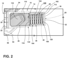
FIG. 2 is a perspective view of the lint filter shown in a closed position with lint particles captured within the filtering space; -
FIG. 3 is a schematic diagram illustrating an aspect of the lint filter and showing operation of the lint filter as process air moves therethrough; -
FIG. 4 is a schematic diagram of the lint filter ofFIG. 3 and showing the lint particles captured within a filtering space after the blower for the appliance is deactivated; -
FIG. 5 is a perspective view of the lint filter ofFIG. 2 and showing captured lint particles within the filtering space; -
FIG. 6 is a schematic diagram illustrating operation of the second panel relative to the first panel as process air moves through the lint filter; -
FIG. 7 is a schematic diagram illustrating operation of the second panel relative to the first panel as process air moves through the lint filter; and -
FIG. 8 is a perspective view of an aspect of the second panel for the lint filter that is attached to the first panel at a hinge member. - The components in the figures are not necessarily to scale, emphasis instead being placed upon illustrating the principles described herein.
- The present illustrated embodiments reside primarily in combinations of method steps and apparatus components related to a lint filter for a laundry appliance that includes a filtering first panel and an operable second panel that operates under air pressure to an open position for capturing particulate matter, such as lint particles, and also closed when the flow of air stops to contain the particulate matter within an enclosed filtering space. Accordingly, the apparatus components and method steps have been represented, where appropriate, by conventional symbols in the drawings, showing only those specific details that are pertinent to understanding the embodiments of the present disclosure so as not to obscure the disclosure with details that will be readily apparent to those of ordinary skill in the art having the benefit of the description herein. Further, like numerals in the description and drawings represent like elements.
- For purposes of description herein, the terms "upper," "lower," "right," "left," "rear," "front," "vertical," "horizontal," and derivatives thereof shall relate to the disclosure as oriented in
FIG. 1 . Unless stated otherwise, the term "front" shall refer to the surface of the element closer to an intended viewer, and the term "rear" shall refer to the surface of the element further from the intended viewer. However, it is to be understood that the disclosure may assume various alternative orientations, except where expressly specified to the contrary. It is also to be understood that the specific devices and processes illustrated in the attached drawings, and described in the following specification are simply exemplary embodiments of the inventive concepts defined in the appended claims. Hence, specific dimensions and other physical characteristics relating to the embodiments disclosed herein are not to be considered as limiting, unless the claims expressly state otherwise. - The terms "including," "comprises," "comprising," or any other variation thereof, are intended to cover a non-exclusive inclusion, such that a process, method, article, or apparatus that comprises a list of elements does not include only those elements but may include other elements not expressly listed or inherent to such process, method, article, or apparatus. An element preceded by "comprises a ... " does not, without more constraints, preclude the existence of additional identical elements in the process, method, article, or apparatus that comprises the element.
- Referring now to
FIGS. 1-8 ,reference numeral 10 generally refers to a lint filter that can be selectively installed or otherwise disposed within a filtration system for an appliance, typically in the form of alaundry appliance 12 for capturingparticulate matter 14, such as lint particles, that are moved along withprocess air 16 through anairflow path 18 during operation of ablower 20 for dehumidifying articles within thelaundry appliance 12. Typically, when theblower 20 is activated, theblower 20 deliversprocess air 16 through theairflow path 18 that includes aprocessing space 60. Thisprocessing space 60 can be within a drum, such as a rotating drum or other container that defines theprocessing space 60 that treats the articles being processed. According to various aspects of the device, thelint filter 10, also referred to herein as a particulate filter, includes ahandle 22 and a filteringfirst panel 24 that extends from thehandle 22. Thefirst panel 24 typically includes amesh filtration member 26 that is used for capturingparticulate matter 14 while allowing filteredprocess air 16 to move therethrough. An operablesecond panel 28 is coupled to thefirst panel 24 at ahinge member 30. Thehinge member 30 is positioned at afirst end 32 of thefirst panel 24 and thehandle 22 is positioned at asecond end 34 of thefirst panel 24. Accordingly, thehinge member 30 opposes thehandle 22 with respect to thefirst panel 24. Thehinge member 30 biases thesecond panel 28 against themesh filtration member 26 to define a closedposition 36. Afiltering space 38 is defined between the first andsecond panels process air 16 through themesh filtration member 26 biases thesecond panel 28 away from themesh filtration member 26 to define anopen position 40 of thelint filter 10. In thisopen position 40,process air 16 moves through themesh filtration member 26 and themesh filtration member 26 separatesparticulate matter 14 from theprocess air 16. In this manner, theparticulate matter 14 is captured within themesh filtration member 26 and within thefiltering space 38. When theblower 20 of thelaundry appliance 12 is deactivated, the flow ofprocess air 16 stops. This deactivation of theblower 20 allows the increase inair pressure 62 to diminish and abiasing force 42 of thehinge member 30 allows thelint filter 10 to be returned to the closedposition 36. In this manner, thesecond panel 28 engages thefirst panel 24 and traps the now capturedparticulate matter 14 between the first andsecond panels filtering space 38. - During operation of the
blower 20,process air 16 moves through theairflow path 18 of theappliance 12 for drying articles within aprocessing space 60.Process air 16 travels through themesh filtration member 26. Due to the mesh size of themesh filtration member 26, at least a portion of theprocess air 16 is temporarily trapped between the first andsecond panels air pressure 62 between the first andsecond panels air pressure 62 overcomes thebiasing force 42 of thehinge member 30 and causes thesecond panel 28 to move away from thefirst panel 24 to define theopen position 40 of thelint filter 10. - In certain aspects of the device, movement of
process air 16 through thelint filter 10 causeseddies 80 of theprocess air 16 and other minute airflows to form between the first andsecond panels eddies 80 generate the increasedair pressure 62 between the first andsecond panels second panel 28 to theopen position 40. - In this
open position 40, it is contemplated that thesecond panel 28 engages a portion of theairflow path 18. In this manner, all or substantially all of theprocess air 16 is directed through themesh filtration member 26 and primarily through thefiltering space 38 defined between the first andsecond panels lint filter 10 is in theopen position 40. - Referring again to
FIGS. 1-8 , thelaundry appliance 12 includes afilter receptacle 90 that selectively receives thelint filter 10. Thisfilter receptacle 90 forms a portion of theairflow path 18 through whichprocess air 16 is delivered for drying articles within theprocessing space 60. In certain aspects of the device, thefilter receptacle 90 can be within atop panel 92 of theappliance 12. In such an aspect of the device, thelint filter 10 can be extracted from thetop panel 92 where thehandle 22 of thelint filter 10 is exposed at the exterior of anouter cabinet 94 for theappliance 12. It is also contemplated that thelint filter 10 can be positioned within a portion of theprocessing space 60. In certain aspects, thelint filter 10 can be positioned within afilter receptacle 90 that is positioned within a lower portion of anaperture 96 that provides access to theprocessing space 60. - Referring again to
FIGS. 1-8 , thelint filter 10 is configured to be placed within thefilter receptacle 90 of thelaundry appliance 12. In this manner, thelint filter 10 can be placed within and extracted from thefilter receptacle 90 for removing capturedparticulate matter 14 from thefiltering space 38. - As exemplified in
FIGS. 1-8 , thesecond panel 28 is attached to thefirst panel 24 at thehinge member 30. It is contemplated that thishinge member 30 can be in the form of a livinghinge 44. This livinghinge 44 can be formed between thesecond panel 28 and aframe 110 of thefirst panel 24 that surrounds themesh filtration member 26 of thefirst panel 24. It is also contemplated that thehinge member 30 can be in the form of a mechanical hinge where thefirst panel 24 andsecond panel 28 meet. Thehinge member 30 can include abiasing mechanism 112 that biases thesecond panel 28 toward thefirst panel 24. In this manner, thesecond panel 28 returns to theclosed position 36 of thelint filter 10. In thisclosed position 36, thefiltering space 38 can be generally enclosed between the first andsecond panels biasing mechanism 112 can be in the form of a spring, a formed livinghinge 44, another elastic member, the force of gravity, combinations thereof and other similar mechanisms for biasing thesecond panel 28 to theclosed position 36 proximate themesh filtration member 26. - It is contemplated that the
hinge member 30 can be incorporated within a single and continuous member that forms theframe 110 of thefirst panel 24 and thesecond panel 28. In such an aspect of the device, the seam that is formed between thefirst panel 24 and thesecond panel 28 can define the livinghinge 44. Thehinge member 30 in the form of the livinghinge 44 can also be incorporated into either thefirst panel 24 or thesecond panel 28. In this aspect of the device, thehinge member 30 can be an extension of thefirst panel 24 that is then attached to thesecond panel 28. Thehinge member 30 can also be an extension of thesecond panel 28 that is then attached to thefirst panel 24. Where thehinge member 30 is an extension of thesecond panel 28, it is contemplated that thesecond panel 28 having thehinge member 30 can be an after-market component that is attached to thefirst panel 24. - The
hinge member 30 can also be part of a separate component, such as athird panel 50, that connects with each of thefirst panel 24 and thesecond panel 28. In such an aspect of the device, thehinge member 30 can include a first hinge panel and a second hinge panel that are joined at the hinge mechanism. As described herein, the hinge mechanism can be in the form of a livinghinge 44, a mechanical hinge having a hinge pin or other rotational interface, or other similar hinge configurations. - When the
blower 20 for thelaundry appliance 12 is deactivated andparticulate matter 14 is captured within thefiltering space 38, thesecond panel 28 is biased toward thefirst panel 24. Through this configuration, thesecond panel 28 trapsparticulate matter 14 within thefiltering space 38. As thelint filter 10 is extracted from thefilter receptacle 90, minimal amounts ofparticulate matter 14, if any, are allowed to be dislodged from themesh filtration member 26 as thelint filter 10 is extracted from thefilter receptacle 90. Certain amounts ofparticulate matter 14 may be dislodged as the user separates thesecond panel 28 from thefirst panel 24 and removes capturedparticulate matter 14 from themesh filtration member 26. Using this configuration, a minimal amount ofparticulate matter 14 are allowed to fly freely through the space surrounding thelaundry appliance 12 as the user removes capturedparticulate matter 14 from thelint filter 10. This creates a minimal amount of mess and debris around thelaundry appliance 12 during use of the dryer. - As exemplified in
FIGS. 1 ,2 ,5 and8 , thesecond panel 28 can include variousstructural formations 120 that are defined within theouter surface 122 of thesecond panel 28. Thesestructural formations 120 can includefine slots 124 that allow a certain amount ofprocess air 16 to move therethrough and provide additional filtering capability within thefiltering space 38. In certain instances, thestructural formations 120 can increase the formation ofeddies 80 that increase theair pressure 62 within thefiltering space 38. Using this configuration, the amount ofair pressure 62 formed between the first andsecond panels filtering space 38 can be increased such that theblower 20 moving at a slower speed can provide a sufficient amount ofprocess air 16 to bias asecond panel 28 away from thefirst panel 24 to define theopen position 40 of thelint filter 10. It is contemplated that the surface of thesecond panel 28 can take various forms and can include thesestructural formations 120 in theouter surface 122 of thesecond panel 28. It is also contemplated that thesecond panel 28 can be smooth or have a rough or texturedouter surface 122 that can take various forms and configurations for allowing theprocess air 16 to bias thesecond panel 28 towards theopen position 40, during operation of theblower 20. - Referring again to
FIGS 1 ,2 ,5 and8 , thesecond panel 28 includes abody portion 100 and a plurality ofapertures 102 defined within thebody portion 100. Theseapertures 102 are formed within thestructural formations 120 of thebody portion 100 for thesecond panel 28 and define asecondary filtration member 104. Thissecondary filtration member 104 assists in separatingparticulate matter 14 from theprocess air 16. Theapertures 102 that are defined within thestructural formations 120 are defined by aresilient frame 106 that surrounds theaperture 102. Thisresilient frame 106 also defines afiltration slot 108 that assists in cooperating with theprocess air 16 to move thesecond panel 28 to theopen position 40. Theresilient frames 106 for therespective apertures 102 of the plurality ofapertures 102 are typically integrally formed with thebody portion 100 of thesecond panel 28. In this manner, thesecond panel 28 and thestructural formations 120 that are formed therein are typically made of a single and continuous member that is molded as a single piece. - According to various aspects of the device, the
first panel 24 extends between thehandle 22 and thehinge member 30. Thesecond panel 28 extends from thehinge member 30 to amedial section 130 of thefirst panel 24. Through this configuration, themesh filtration member 26 of thefirst panel 24 includes thefiltering space 38 that is defined between the first andsecond panels air directing space 132 that is positioned between thehandle 22 and anouter edge 134 of thesecond panel 28. Thisair directing space 132 directsprocess air 16 into thefiltering space 38 between the first andsecond panels air pressure 62 that moves thesecond panel 28 to theopen position 40 and expands thefiltering space 38 to receive theprocess air 16. - According to various aspects of the device, the
lint filter 10 provides for an operablesecond panel 28 that can be used for containing capturedparticulate matter 14 within afiltering space 38 and preventing theseparticulate matter 14 from being dislodged as thelint filter 10 is removed from thefilter receptacle 90. It is also contemplated that thelint filter 10 described herein can be used within any one or more ofvarious appliances 12.Such appliances 12 can include, but are not limited to, vented dryers, recirculating dryers, heat pump dryers, condensing dryers, combination washing and drying appliances, air handling units, and other similar appliances that filter a flow of air by using a filtration member. It is also contemplated that theappliance 12 may includemultiple lint filters 10 that may includefiltration members 26 having different mesh sizes. - According to the various aspects of the device, the particulate filter, such as the
lint filter 10, can be incorporated within any one of a variety ofappliances 12.Such appliances 12 can include, but are not limited to, laundry appliances, refreshing appliances, dishwashers, air handling units, air conditioning units, vent hoods, refrigerating units and other appliances that include a filtration mechanism for an air handling system. - The invention disclosed herein is further summarized in the following paragraphs and is further characterized by combinations of any and all of the various aspects described therein.
- According to an aspect of the present disclosure, a lint filter for a laundry appliance includes a handle, a first panel that extends from the handle and has a mesh filtration member, and a second panel that is coupled to the first panel at a hinge member that opposes the handle. The hinge member biases the second panel against the mesh filtration member to define a closed position, and a flow of process air through the mesh filtration member moves the second panel away from the mesh filtration member to define an open position that forms a filtering space for capturing particulate matter from the process air. Upon deactivation of the flow of the process air, the lint filter returns to the closed position that is configured to trap the particulate matter in the filtering space and between the first and second panels.
- According to another aspect, the lint filter is configured to be placed within a filter receptacle of said laundry appliance.
- According to another aspect, the filter receptacle is positioned within a top panel of a cabinet of said laundry appliance.
- According to another aspect, the hinge member is a mechanical hinge that connects the first panel and the second panel.
- According to another aspect, the mechanical hinge includes a biasing mechanism that biases the first panel and the second panel toward the closed position.
- According to another aspect, the first panel includes a frame that surrounds the mesh filtration member, and the hinge member is attached to the frame.
- According to another aspect, the frame and the second panel are a single and continuous member, and the hinge member is a living hinge that is defined between the first panel and the second panel.
- According to another aspect, the hinge member is a living hinge that is defined within the second panel.
- According to another aspect, the second panel that has the hinge member is attached to the first panel.
- According to another aspect, the second panel that has the hinge member is an after-market component that is attached to the first panel.
- According to another aspect, the second panel includes a body portion and a plurality of apertures that are defined within the body portion that define a secondary filtration member.
- According to another aspect, each aperture of the plurality of apertures includes a resilient frame that defines a filtration slot that assists in cooperating with the process air to move the second panel to the open position.
- According to another aspect, the resilient frame of each aperture is integrally formed with the body portion of the second panel.
- According to another aspect, the hinge member is a third panel that extends between the first panel and the second panel.
- According to another aspect, the third panel includes the hinge member in a form of a living hinge.
- According to another aspect of the present disclosure, a laundry appliance includes a blower that delivers process air through an airflow path that is disposed within an outer cabinet. A drum defines a processing space that treats articles, wherein the airflow path includes the processing space. A lint filter is selectively disposed within the airflow path. The lint filter includes a first panel that selectively extends into the airflow path and has a filtration member and a handle, and a second panel that is coupled to the first panel at a hinge member that opposes the handle. The hinge member biases the second panel against the first panel to define a closed position. Activation of the blower directs the process air through the filtration member and also biases the second panel away from the first panel to define an open position that forms a filtering space between the second panel and the filtration member. Upon deactivation of the blower, the second panel returns to the closed position that traps particulate matter within the filtering space and between the second panel and the filtration member.
- According to another aspect, the lint filter is selectively received within a receptacle that extends into the airflow path.
- According to another aspect, the receptacle is defined within a top panel of the outer cabinet.
- According to another aspect of the present disclosure, a filtration system for an appliance includes a blower that delivers process air through an airflow path. A particulate filter is selectively disposed within the airflow path. The particulate filter includes a first panel that extends between a handle and a hinge member, a mesh filtration member that is disposed within the first panel that is configured to separate particulate matter from the process air to define captured particulate matter, and a second panel that is coupled to the hinge member and cooperates with the mesh filtration member to define a filtering space therebetween. The hinge member biases the second panel to a closed position proximate the mesh filtration member. Activation of the blower directs the process air through the filtering space and defines an increased air pressure within the filtering space that moves the second panel to an open position that expands the filtering space. Upon deactivation of the blower, the second panel is biased to the closed position that traps the captured particulate matter within the filtering space and between the second panel and the mesh filtration member.
- According to another aspect, the particulate filter is disposed within the airflow path through an opening in an outer cabinet that surrounds the airflow path.
Claims (15)
- A lint filter (10) for a laundry appliance (12), the lint filter (12) comprising:a handle (22);a first panel (24) that extends from the handle (22) and having a mesh filtration member (26); anda second panel (28) that is coupled to the first panel (24) at a hinge member (30) that opposes the handle (22), wherein the hinge member (30) biases the second panel (28) against the mesh filtration member (26) to define a lint filter closed position (36), and the lint filter (10) being configured so that a flow of process air (16) through the mesh filtration member (26) moves the second panel (28) away from the mesh filtration member (26) to define a lint filter open position (40) that forms a filtering space (38) for capturing particulate matter (14) from the process air (16), and where upon deactivation of the flow of the process air (16), the lint filter (10) returns to the closed position (36) that is configured to trap the particulate matter (14) in the filtering space (38) and between the first and second panels (24, 28).
- The lint filter (10) of claim 1, wherein the lint filter (10) is configured to be placed within a filter receptacle (90) of said laundry appliance (12).
- The lint filter (10) of claim 2, wherein the filter receptacle (90) is positioned within a top panel (92) of a cabinet (94) of said laundry appliance (12).
- The lint filter (10) of any one of claims 1-3, wherein the hinge member (30) is a mechanical hinge that connects the first panel (24) and the second panel (28).
- The lint filter (10) of claim 4, wherein the mechanical hinge includes a biasing mechanism (112) that biases the first panel (24) and the second panel (28) toward the lint filter closed position (36).
- The lint filter (10) of any one of claims 1-5, wherein the hinge member (30) is a living hinge (44) that is defined within the second panel (28).
- The lint filter (10) of any one of claims 1-6, wherein the second panel (28) having the hinge member (30) is attached to the first panel (24).
- The lint filter (10) of claim 7, wherein the second panel (28) having the hinge member (30) is detachably attached to the first panel (24).
- The lint filter (10) of claim 8, wherein the second panel (28) is an after-market component.
- The lint filter (10) of any one of claims 1-9, wherein the second panel (28) includes a body portion (100) and a plurality of apertures (102) defined within the body portion (100) that define a secondary filtration member (104).
- The lint filter (10) of claim 10, wherein each aperture (102) of the plurality of apertures (102) includes a resilient frame (106) that defines a filtration slot (108) that assists in cooperating with the process air (16) to move the second panel (28) to the open position (40).
- The lint filter (10) of claim 11, wherein the resilient frame (106) of each aperture (102) is integrally formed with the body portion (100) of the second panel (28).
- The lint filter (10) of any one of claims 1-12, further comprising a third panel (50) that extends between the first panel (24) and the second panel (28), wherein the third panel (50) includes the hinge member (30) in a form of a living hinge (44).
- The lint filter (10) of any one of claims 1-13, wherein the first panel (24) includes a frame (110) that surrounds the mesh filtration member (26), and wherein the hinge member (30) is attached to the frame (110).
- The lint filter (10) of claim 14, wherein the frame (110) and the second panel (28) are a single and continuous member, and wherein the hinge member (30) is a living hinge (44) that is defined between the first panel (24) and the second panel (28).
Applications Claiming Priority (2)
| Application Number | Priority Date | Filing Date | Title |
|---|---|---|---|
| US202263332713P | 2022-04-20 | 2022-04-20 | |
| US18/121,248 US12618189B2 (en) | 2022-04-20 | 2023-03-14 | Lint filter for laundry appliance having a closable filtering space for capturing lint particles |
Publications (1)
| Publication Number | Publication Date |
|---|---|
| EP4265836A1 true EP4265836A1 (en) | 2023-10-25 |
Family
ID=86052870
Family Applications (1)
| Application Number | Title | Priority Date | Filing Date |
|---|---|---|---|
| EP23168349.1A Withdrawn EP4265836A1 (en) | 2022-04-20 | 2023-04-17 | Lint filter for laundry appliance having a closable filtering space for capturing lint particles |
Country Status (3)
| Country | Link |
|---|---|
| US (1) | US12618189B2 (en) |
| EP (1) | EP4265836A1 (en) |
| BR (1) | BR102023007386A2 (en) |
Citations (3)
| Publication number | Priority date | Publication date | Assignee | Title |
|---|---|---|---|---|
| US4653200A (en) * | 1986-03-05 | 1987-03-31 | Whirlpool Corporation | Lint screen shield assembly for a dryer |
| US6101741A (en) * | 1998-04-15 | 2000-08-15 | Maytag Corporation | Gravity assisted lint trap |
| US20140208603A1 (en) * | 2013-01-25 | 2014-07-31 | Youngsuk Kim | Laundry treatment apparatus |
Family Cites Families (10)
| Publication number | Priority date | Publication date | Assignee | Title |
|---|---|---|---|---|
| US2509300A (en) * | 1948-04-05 | 1950-05-30 | Kenneth E Hendrickson | Lint trap |
| DE8032679U1 (en) | 1980-12-09 | 1982-02-25 | G. Bauknecht Gmbh, 7000 Stuttgart | LAUNDRY DRYER |
| US4856348A (en) | 1983-11-21 | 1989-08-15 | Great Plains, Industries, Inc. | Flow meter turbine |
| DE8437357U1 (en) | 1984-12-20 | 1985-03-21 | Bosch-Siemens Hausgeräte GmbH, 7000 Stuttgart | HOUSEHOLD LAUNDRY DRYER WITH A FLUSH FILTER |
| EP2562304B1 (en) | 2011-08-24 | 2017-03-08 | Electrolux Home Products Corporation N.V. | Air stream filter for a laundry dryer |
| EP2682513A1 (en) * | 2012-07-06 | 2014-01-08 | Electrolux Home Products Corporation N.V. | Laundry dryer |
| CN104452236B (en) | 2013-09-18 | 2018-08-07 | 佛山海尔滚筒洗衣机有限公司 | A kind of adjustable filter device and dryer of dryer |
| KR102633056B1 (en) | 2018-10-29 | 2024-02-02 | 삼성전자주식회사 | Filter assembly and dryer for the same |
| US11603623B2 (en) * | 2021-03-18 | 2023-03-14 | Haier Us Appliance Solutions, Inc. | Lint filter latch |
| US12378716B2 (en) * | 2021-06-09 | 2025-08-05 | Whirlpool Corporation | Laundry appliance |
-
2023
- 2023-03-14 US US18/121,248 patent/US12618189B2/en active Active
- 2023-04-17 EP EP23168349.1A patent/EP4265836A1/en not_active Withdrawn
- 2023-04-19 BR BR102023007386-7A patent/BR102023007386A2/en not_active Application Discontinuation
Patent Citations (3)
| Publication number | Priority date | Publication date | Assignee | Title |
|---|---|---|---|---|
| US4653200A (en) * | 1986-03-05 | 1987-03-31 | Whirlpool Corporation | Lint screen shield assembly for a dryer |
| US6101741A (en) * | 1998-04-15 | 2000-08-15 | Maytag Corporation | Gravity assisted lint trap |
| US20140208603A1 (en) * | 2013-01-25 | 2014-07-31 | Youngsuk Kim | Laundry treatment apparatus |
Also Published As
| Publication number | Publication date |
|---|---|
| US12618189B2 (en) | 2026-05-05 |
| BR102023007386A2 (en) | 2023-10-24 |
| US20230340715A1 (en) | 2023-10-26 |
Similar Documents
| Publication | Publication Date | Title |
|---|---|---|
| EP3118366B1 (en) | Clothes dryer | |
| EP2843123B1 (en) | Appliance for drying laundary with auxiliary de-fluff filter | |
| KR100633605B1 (en) | Dust collection unit of vacuum cleaner | |
| EP2843103B1 (en) | Appliance for drying laundary with auxiliary de-fluff filter | |
| EP3118368B1 (en) | Clothes dryer | |
| KR101070485B1 (en) | Dryer and apparatus for removing lint thereof | |
| EP2202350B1 (en) | A dryer and foreign material removing apparatus thereof | |
| US7950104B2 (en) | Vacuum cleaner having dust-separating apparatus with shutter unit | |
| KR102739008B1 (en) | Apparatus for treating clothes | |
| EP1725707A2 (en) | A washer / dryer | |
| US10941513B2 (en) | Hinged housing for a lint trap of a dryer appliance | |
| GB2091123A (en) | Filter for clothes dryer | |
| US12618189B2 (en) | Lint filter for laundry appliance having a closable filtering space for capturing lint particles | |
| EP4086384A1 (en) | Side access panel for lint filter of laundry appliance | |
| EP1947232B1 (en) | Household clothes drying machine with vibrating lint filter | |
| EP3246455B1 (en) | Laundry treating machine comprising a removable de-fluff filter | |
| WO2018068707A1 (en) | Clothes dryer having shield | |
| US1918764A (en) | Vacuum cleaner | |
| TW202012736A (en) | Clothes dryer | |
| JP7113308B2 (en) | clothes dryer | |
| EP4137634A1 (en) | Foreign particulate removal assembly of a laundry appliance | |
| US12630967B2 (en) | Foreign particulate removal assembly of a laundry appliance | |
| KR102336632B1 (en) | Kitchen air purifier | |
| EP4183915A1 (en) | Laundry handling device |
Legal Events
| Date | Code | Title | Description |
|---|---|---|---|
| STAA | Information on the status of an ep patent application or granted ep patent |
Free format text: STATUS: THE APPLICATION HAS BEEN PUBLISHED |
|
| PUAI | Public reference made under article 153(3) epc to a published international application that has entered the european phase |
Free format text: ORIGINAL CODE: 0009012 |
|
| AK | Designated contracting states |
Kind code of ref document: A1 Designated state(s): AL AT BE BG CH CY CZ DE DK EE ES FI FR GB GR HR HU IE IS IT LI LT LU LV MC ME MK MT NL NO PL PT RO RS SE SI SK SM TR |
|
| P01 | Opt-out of the competence of the unified patent court (upc) registered |
Effective date: 20231220 |
|
| STAA | Information on the status of an ep patent application or granted ep patent |
Free format text: STATUS: REQUEST FOR EXAMINATION WAS MADE |
|
| 17P | Request for examination filed |
Effective date: 20240402 |
|
| RBV | Designated contracting states (corrected) |
Designated state(s): AL AT BE BG CH CY CZ DE DK EE ES FI FR GB GR HR HU IE IS IT LI LT LU LV MC ME MK MT NL NO PL PT RO RS SE SI SK SM TR |
|
| STAA | Information on the status of an ep patent application or granted ep patent |
Free format text: STATUS: THE APPLICATION HAS BEEN WITHDRAWN |
|
| 18W | Application withdrawn |
Effective date: 20250331 |