EP4265829A1 - Heater - Google Patents
Heater Download PDFInfo
- Publication number
- EP4265829A1 EP4265829A1 EP23162283.8A EP23162283A EP4265829A1 EP 4265829 A1 EP4265829 A1 EP 4265829A1 EP 23162283 A EP23162283 A EP 23162283A EP 4265829 A1 EP4265829 A1 EP 4265829A1
- Authority
- EP
- European Patent Office
- Prior art keywords
- yarn
- contacted member
- heater
- height direction
- yarn contacted
- Prior art date
- Legal status (The legal status is an assumption and is not a legal conclusion. Google has not performed a legal analysis and makes no representation as to the accuracy of the status listed.)
- Granted
Links
Images



Classifications
-
- D—TEXTILES; PAPER
- D02—YARNS; MECHANICAL FINISHING OF YARNS OR ROPES; WARPING OR BEAMING
- D02G—CRIMPING OR CURLING FIBRES, FILAMENTS, THREADS, OR YARNS; YARNS OR THREADS
- D02G1/00—Producing crimped or curled fibres, filaments, yarns, or threads, giving them latent characteristics
- D02G1/004—Producing crimped or curled fibres, filaments, yarns, or threads, giving them latent characteristics by heating fibres, filaments, yarns or threads so as to create a temperature gradient across their diameter, thereby imparting them latent asymmetrical shrinkage properties
-
- D—TEXTILES; PAPER
- D02—YARNS; MECHANICAL FINISHING OF YARNS OR ROPES; WARPING OR BEAMING
- D02J—FINISHING OR DRESSING OF FILAMENTS, YARNS, THREADS, CORDS, ROPES OR THE LIKE
- D02J13/00—Heating or cooling the yarn, thread, cord, rope, or the like, not specific to any one of the processes provided for in this subclass
- D02J13/003—Heating or cooling the yarn, thread, cord, rope, or the like, not specific to any one of the processes provided for in this subclass by contact with at least one stationary surface, e.g. a plate
-
- D—TEXTILES; PAPER
- D02—YARNS; MECHANICAL FINISHING OF YARNS OR ROPES; WARPING OR BEAMING
- D02G—CRIMPING OR CURLING FIBRES, FILAMENTS, THREADS, OR YARNS; YARNS OR THREADS
- D02G1/00—Producing crimped or curled fibres, filaments, yarns, or threads, giving them latent characteristics
- D02G1/02—Producing crimped or curled fibres, filaments, yarns, or threads, giving them latent characteristics by twisting, fixing the twist and backtwisting, i.e. by imparting false twist
- D02G1/0206—Producing crimped or curled fibres, filaments, yarns, or threads, giving them latent characteristics by twisting, fixing the twist and backtwisting, i.e. by imparting false twist by false-twisting
-
- D—TEXTILES; PAPER
- D02—YARNS; MECHANICAL FINISHING OF YARNS OR ROPES; WARPING OR BEAMING
- D02G—CRIMPING OR CURLING FIBRES, FILAMENTS, THREADS, OR YARNS; YARNS OR THREADS
- D02G1/00—Producing crimped or curled fibres, filaments, yarns, or threads, giving them latent characteristics
- D02G1/02—Producing crimped or curled fibres, filaments, yarns, or threads, giving them latent characteristics by twisting, fixing the twist and backtwisting, i.e. by imparting false twist
- D02G1/0206—Producing crimped or curled fibres, filaments, yarns, or threads, giving them latent characteristics by twisting, fixing the twist and backtwisting, i.e. by imparting false twist by false-twisting
- D02G1/0266—Producing crimped or curled fibres, filaments, yarns, or threads, giving them latent characteristics by twisting, fixing the twist and backtwisting, i.e. by imparting false twist by false-twisting false-twisting machines
-
- D—TEXTILES; PAPER
- D02—YARNS; MECHANICAL FINISHING OF YARNS OR ROPES; WARPING OR BEAMING
- D02G—CRIMPING OR CURLING FIBRES, FILAMENTS, THREADS, OR YARNS; YARNS OR THREADS
- D02G1/00—Producing crimped or curled fibres, filaments, yarns, or threads, giving them latent characteristics
- D02G1/20—Combinations of two or more of the above-mentioned operations or devices; After-treatments for fixing crimp or curl
Definitions
- the present invention relates to a heater configured to heat a yarn.
- Patent Literature 1 Japanese Laid-Open Patent Publication No. 2002-194631 discloses a heater provided in a false-twist texturing machine (textile machine) configured to perform false twisting of a running yarn.
- the heater includes a sheathed heater (heat source), a heating body (heating unit) extending in a predetermined extending direction, and a contact plate (yarn contacted member) which is attached to the heating unit and which is heated by the heat source.
- the yarn contacted member is provided with a yarn contacted surface curved to be reliably made contact with the yarn. With this arrangement, the yarn running while being in contact with the yarn contacted surface is heated by means of heat conduction.
- the specifications (to be more specific, a suitable curvature of a yarn path formed by the yarn contacted surface) of the above-described heater may vary mainly because of the layout of the textile machine forming the yarn path.
- a yarn contacted member is processed in advance based on the specifications of a heater so that a yarn path has a suitable curvature. Therefore, production cost is high.
- An object of the present invention is to achieve the reduction in production cost of a yarn contacted member applied to a heater.
- a heater is configured to heat a running yarn, and includes: a heat source; a heating unit which extends in a predetermined extending direction and which is heated by the heat source; a yarn contacted member which has a yarn contacted surface, which extends at least in the extending direction, and which is heated by the heating unit, the yarn making contact with the yarn contacted surface; and an attaching portion which includes the heating unit and to which the yarn contacted member is attached.
- the yarn contacted surface extends at least in the extending direction and is oriented at least to one side in a predetermined height direction orthogonal to the extending direction.
- This heater further includes an elastic deformation holding unit configured to hold the yarn contacted member attached to the attaching portion while elastically deforming the yarn contacted member viewed in a width direction orthogonal to the extending direction and the height direction.
- an elastic deformation holding unit configured to hold the yarn contacted member attached to the attaching portion while elastically deforming the yarn contacted member viewed in a width direction orthogonal to the extending direction and the height direction.
- the cross sectional curve of the yarn contacted surface has a predetermined curvature in such a way that the elastic deformation holding unit holds the yarn contacted member which is attached to the attaching portion while being elastically deformed.
- the yarn contacted surface has a desired shape only in such a way that the yarn contacted member is elastically deformed.
- the heater of the first aspect is arranged such that the elastic deformation holding unit is configured to hold the yarn contacted member so that the yarn contacted member is attachable to and detachable from the attaching portion.
- the heater may be provided at a position higher than the stature of an operator who cleans the member. Therefore, when the yarn contacted member cannot be detached from the attaching portion, the cleaning of the member may be difficult depending on the position of the heater.
- the present invention makes it possible to detach the yarn contacted member from the attaching portion at the time of cleaning. It is therefore possible to improve the work efficiency in cleaning of the yarn contacted member, irrespective of the position of the heater.
- the heater of the second aspect is arranged such that an attachment-detachment path through which the yarn contacted member is able to pass in the height direction at the time of attachment and detachment of the yarn contacted member is formed in the attaching portion.
- the yarn contacted member may be attached to and detached from the attaching portion by being inserted in and pulled out from the attaching portion in the extending direction.
- a long space provided for the attachment and detachment of the yarn contacted member is required at a position adjacent to the heater in the extending direction.
- the yarn contacted member is attachable to and detachable from the attaching portion by moving the yarn contacted member in the height direction.
- the above-described long space at the position adjacent to the heater in the extending direction is not required. It is therefore possible to suppress the occurrence of disadvantages such as the limit on the layout of the heater and its surroundings.
- the heater of any one of the first to third aspects is arranged such that the elastic deformation holding unit includes: a first force portion configured to apply the force toward one side in the height direction to a first part of the yarn contacted member attached to the attaching portion, the first part being at a predetermined position in the extending direction; a second force portion configured to apply the force toward the other side in the height direction to a second part of the yarn contacted member attached to the attaching portion, the second part being provided on one side in the extending direction as compared to the first part; and a third force portion configured to apply the force toward the other side in the height direction to a third part of the yarn contacted member attached to the attaching portion, the third part being provided on the other side in the extending direction as compared to the first part.
- the force toward one side in the height direction is applied to a part of the yarn contacted member in the extending direction.
- one part of the yarn contacted member is provided on one side in the extending direction and another part of the yarn contacted member is provided on the other side in the extending direction.
- the force toward the other side in the height direction is applied to these two parts.
- the heater of the fourth aspect is arranged such that the first force portion includes a first regulatory portion which is provided on the other side in the height direction as compared to the first part and which is configured to regulate the movement of the first part toward the other side in the height direction, the second force portion includes a second regulatory portion which is provided on one side in the height direction as compared to the second part and which is configured to regulate the movement of the second part toward one side in the height direction, and the third force portion includes a third regulatory portion which is provided on one side in the height direction as compared to the third part and which is configured to regulate the movement of the third part toward one side in the height direction.
- the force toward one side in the height direction is applied to the first part on account of the law of action and reaction in such a way that the first regulatory portion regulates the movement of the first part toward the other side in the height direction.
- the force toward the other side in the height direction is applied to the second part and the third part on account of the law of action and reaction in such a way that the second regulatory portion and the third regulatory portion regulate the movement of the second part and third part toward one side in the height direction. It is therefore possible to elastically deform the yarn contacted member with a simple structure.
- the heater of the fifth aspect is arranged such that, when each of the second regulatory portion and the third regulatory portion is viewed in the height direction, the each of the second regulatory portion and the third regulatory portion is movable between a retracted position which does not overlap the yarn contacted member and an overlapping position which overlaps the yarn contacted member.
- the yarn contacted member when the yarn contacted member is to be attached to the attaching portion, the yarn contacted member is attached to the attaching portion in such a simple way that (i) the each of the second regulatory portion and the third regulatory portion is temporarily moved to the retracted position and then (ii) the each of the second regulatory portion and the third regulatory portion is moved back to the overlapping position while the yarn contacted member is warped.
- the yarn contacted member is attachable to and detachable from the attaching portion, the yarn contacted member is detached from the attaching portion in such a simple way that the each of the second regulatory portion and the third regulatory portion is temporarily moved to the retracted position.
- the heater of the sixth aspect further includes a biasing portion configured to bias the each of the second regulatory portion and the third regulatory portion from the retracted position to the overlapping position.
- the heater of the sixth or seventh aspect further includes a swing axis configured to swingably support the each of the second regulatory portion and the third regulatory portion.
- the second regulatory portion and the third regulatory portion may be movable in a parallel manner. In this case, however, a large space is required for the movement of the second regulatory portion and the third regulatory portion. According to this aspect, for example, when the yarn contacted member is to be attached to the attaching portion in the production of the heater (or when the yarn contacted member which is attachable to and detachable from the attaching portion is to be detached from the attaching portion), a space required for the movement of the second regulatory portion and the third regulatory portion is downsized.
- the heater of any one of the fifth to eighth aspects is arranged such that the position of at least one of the first regulatory portion, the second regulatory portion, and the third regulatory portion is changeable with respect to the attaching portion in at least one of the extending direction and the height direction.
- the curvature of the cross sectional curve of the yarn contacted surface is adjustable according to need even after the heater is set.
- the direction perpendicular to the sheet of FIG. 1 will be referred to as a base longitudinal direction.
- the left-right direction of the sheet of FIG. 1 will be referred to as a base width direction.
- the direction orthogonal to the base longitudinal direction and the base width direction will be referred to as an up-down direction (vertical direction) in which the gravity acts.
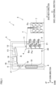
- FIG. 1 is a profile of the false-twist texturing machine 1.
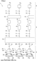
- FIG. 2 is a schematic diagram of the false-twist texturing machine 1, expanded along paths of yarns Y (yarn paths).
- the false-twist texturing machine 1 is able to perform false twisting of yarns Y (to false-twist yarns Y) made of synthetic fibers (e.g., polyester).
- Each yarn Y is, e.g., a multi-filament yarn formed of filaments. Alternatively, each yarn Y may be formed of a single filament.
- the false-twist texturing machine 1 includes a yarn supplying unit 2, a processing unit 3, and a winding unit 4.
- the yarn supplying unit 2 is able to supply yarns Y.
- the processing unit 3 is configured to pull out the yarns Y from the yarn supplying unit 2, and to false-twist the yarns Y.
- the winding unit 4 is configured to wind the yarns Y processed by the processing unit 3 onto winding bobbins Bw. Components of the yarn supplying unit 2, the processing unit 3, and the winding unit 4 are aligned to form plural lines (see FIG. 2 ) in the base longitudinal direction.
- the base longitudinal direction is a direction orthogonal to a running plane (plane of FIG. 1 ) of the yarns Y.
- the running plane of the yarns Y is formed of the yarn paths extending from the yarn supplying unit 2 to the winding unit 4 through the processing unit 3.
- the yarn supplying unit 2 includes a creel stand 7 retaining yarn supply packages Ps, and is configured to supply the yarns Y to the processing unit 3.
- the processing unit 3 is configured to pull out the yarns Y from the yarn supplying unit 2, and to process the yarns Y.
- the following members are provided in this order from the upstream side in a yarn running direction: each first feed roller 11; each twist-stopping guide 12; each first heater 13; each cooler 14; each false-twisting device 15; each second feed roller 16; each interlacing device 17; each third feed roller 18; a second heater 19; and each fourth feed roller 20.
- the winding unit 4 includes winding devices 21. Each winding device 21 is configured to wind a yarn Y for which the false twisting has been performed by the processing unit 3 onto a winding bobbin Bw, and to form a wound package Pw.
- the false-twist texturing machine 1 includes a main frame 8 and a winding base 9 which are spaced apart from each other in the base width direction.
- the main frame 8 and the winding base 9 are substantially identical in length in the base longitudinal direction.
- the main frame 8 and the winding base 9 oppose each other in the base width direction.
- the false-twist texturing machine 1 includes units termed spans each of which includes a pair of the main frame 8 and the winding base 9. In one span, each device is placed so that the false twisting is simultaneously performable for the yarns Y running while being aligned in the base longitudinal direction.
- the spans are placed in a left-right symmetrical manner to the sheet, with a center line C of the base width direction of the main frame 8 as a symmetry axis. (That is, the main frame 8 is shared between the left span and the right span.)
- the spans are aligned in the base longitudinal direction.
- Each first feed roller 11 is configured to unwind a yarn Y from one yarn supply package Ps attached to the yarn supplying unit 2, and to send the yarn Y to one first heater 13. As shown in FIG. 2 , each first feed roller 11 is configured to send, e.g., a single yarn Y to the first heater 13. Alternatively, each first feed roller 11 may be able to send plural adjacent yarns Y to the downstream side in the yarn running direction.
- Each twist-stopping guide 12 prevents twisting, which is applied to a yarn Y by one later-described false-twisting device 15, from being propagated to the upstream of each twist-stopping guide 12 in the yarn running direction.
- Each first heater 13 is configured to increase the temperature of yarns Y sent from some first feed rollers 11 to a predetermined processing temperature. As shown in FIG. 2 , each first heater 13 is able to heat, e.g., two yarns Y. Below the first heater 13, there is a working space S (see FIG. 1 ) provided for an operator to perform yarn threading, etc. Each first heater 13 will be detailed later.
- Each cooler 14 is configured to cool a yarn Y heated by one first heater 13. As shown in FIG. 2 , each cooler 14 is configured to cool, e.g., a single yarn Y. Alternatively, the cooler 14 may be able to simultaneously cool plural yarns Y.
- Each false-twisting device 15 is provided downstream of one cooler 14 in the yarn running direction, and configured to twist a yarn Y. Each false-twisting device 15 is, e.g., a so-called disc-friction false-twisting device. However, the disclosure is not limited to this.
- Each second feed roller 16 is configured to send a yarn Y processed by one false-twisting device 15 to one interlacing device 17.
- the conveyance speed of conveying the yarn Y by each second feed roller 16 is higher than the conveyance speed of conveying the yarn Y by each first feed roller 11. Because of this, the yarn Y is therefore drawn and false-twisted between each first feed roller 11 and each second feed roller 16.
- Each interlacing device 17 is configured to interlace a yarn Y.
- Each interlacing device 17 has, e.g., a known interlace nozzle configured to interlace the yarn Y by means of an airflow.
- Each third feed roller 18 is configured to send, to the second heater 19, a yarn Y running on the downstream side of one interlacing device 17 in the yarn running direction. As shown in FIG. 2 , each third feed roller 18 is configured to send, e.g., a single yarn Y to the second heater 19. Alternatively, each third feed roller 18 may be able to send plural adjacent yarns Y to the downstream side in the yarn running direction. The conveyance speed of conveying the yarn Y by each third feed roller 18 is lower than the conveyance speed of conveying the yarn Y by each second feed roller 16. The yarn Y is therefore relaxed between each second feed roller 16 and each third feed roller 18. The second heater 19 is configured to heat yarns Y sent from some third feed rollers 18.
- the second heater 19 extends along the vertical direction, and is provided for each of the spans.
- Each fourth feed roller 20 is configured to send a yarn Y heated by the second heater 19 to one winding device 21. As shown in FIG. 2 , each fourth feed roller 20 is able to send, e.g., a single yarn Y to the winding device 21. Alternatively, each fourth feed roller 20 may be able to send plural adjacent yarns Y to the downstream side in the yarn running direction. The conveyance speed of conveying the yarn Y by each fourth feed roller 20 is lower than the conveyance speed of conveying the yarn Y by each third feed roller 18. The yarn Y is therefore relaxed between each third feed roller 18 and each fourth feed roller 20.
- each yarn Y drawn between the first feed roller 11 and the second feed roller 16 is twisted by the false-twisting device 15.
- the twist formed by the false-twisting device 15 propagates to the twist-stopping guide 12, but does not propagate to the upstream side of the twist-stopping guide 12 in the yarn running direction.
- the yarn Y which is twisted and drawn is heated by the first heater 13 and thermally set. After that, the yarn Y is cooled by the cooler 14.
- the yarn Y is untwisted on the downstream side of the false-twisting device 15 in the yarn running direction.
- the yarn Y is maintained to be wavy in shape on account of the thermal setting described above (i.e., crimp contraction of the yarn Y is maintained).
- the yarn Y After being false-twisted, the yarn Y is interlaced by the interlacing device 17 while being relaxed between the second feed roller 16 and the third feed roller 18. The yarn Y is then guided to the downstream side in the yarn running direction. Furthermore, the yarn Y is thermally set by the second heater 19 while being relaxed between the third feed roller 18 and the fourth feed roller 20. Finally, the yarn Y which is sent from the fourth feed roller 20 is wound by the winding device 21.
- the winding unit 4 includes plural winding devices 21. Each winding device 21 is able to wind one yarn Y onto one winding bobbin Bw.
- the winding device 21 includes a fulcrum guide 31, a traverse unit 32, and a cradle 33.
- the fulcrum guide 31 is a guide functioning as a fulcrum when the yarn Y is traversed.
- the traverse unit 32 is able to traverse the yarn Y by means of a traverse guide 34.
- the cradle 33 is configured to rotatably support the winding bobbin Bw.
- a contact roller 35 is provided in the vicinity of the cradle 33.
- the contact roller 35 is configured to make contact with a surface of one wound package Pw so as to apply a contact pressure to the surface of the wound package Pw.
- the yarn Y sent from the above-described fourth feed roller 20 is wound onto the winding bobbin Bw by the winding device 21 so that the wound package Pw is formed.
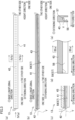
- FIG. 3(a) shows one first heater 13 viewed in the base longitudinal direction.
- FIG. 3(a) illustrates the first heater 13 extending along the left-right direction of the sheet of FIG. 3 (a).
- FIG. 3(b) is a cross section of the first heater 13, which is taken along a direction orthogonal to the base longitudinal direction.
- FIG. 3(b) illustrates a yarn contacted surface 57 (described later) of a yarn contacted member 43 (described later).
- FIG. 3(c) is an enlarged view of a left end part of FIG. 3(b).
- FIG. 3(d) is an enlarged view of one end of the yarn contacted member 43 of the first heater 13 in an extending direction.
- FIG. 3(e) is a cross section taken along a line III(e)-III(e) in FIG. 3(d) .
- FIG. 4(a) is a view of FIG. 3(a) viewed along an arrow IV(a) in FIG. 3(a) .
- FIG. 4(b) is a cross section taken along a line IV(b)-IV(b) in FIG. 3(a) .
- the left-right direction of the sheet of each of FIGs. 3(a) and 3(b) will be referred to as the extending direction in which the first heater 13 extends.
- the extending direction is orthogonal to the base longitudinal direction.
- the left side of the sheet of each of FIGs. 3(a) and 3(b) is defined as one side in the extending direction
- the right side of the sheet of each of FIGs. 3(a) and 3(b) is defined as the other side in the extending direction.
- the direction orthogonal to the base longitudinal direction and the extending direction will be referred to as a height direction.
- FIGs. 4(a) and 4(b) is defined as one side in the height direction, and the upper side of the sheet of each of FIGs. 3(a) and 3(b) and FIGs. 4(a) and 4(b) is defined as the other side in the height direction.
- FIGs. 3(c) to 3(e) FIGs. 6(a) to 6(d)
- FIGs. 7(a) and 7(b) described later.
- one side in the height direction is close to the working space S (see FIG. 1 ) as compared to the other side in the height direction.
- one side in the height direction may be referred to as the "working space S side".
- the other side in the height direction may be referred to as the "opposite side from the working space S".
- the base longitudinal direction may be referred to as a width direction (see FIG. 3(e) , FIG. 4(a), and FIG. 4(b) ).
- the width direction is orthogonal to the extending direction and the height direction.
- the first heater 13 is configured to heat at least one running yarn Y.
- the first heater 13 is able to heat, e.g., two yarns Y (yarns YA and YB: see FIG. 4(a) ).
- the first heater 13 includes two heating units 41 (heating units 41A and 41B: an attaching portion of the present invention), a heat source 42, and two yarn contacted members 43 (yarn contacted members 43A and 43B).
- the first heater 13 is structured so that (i) the heat source 42 heats the yarn contacted members 43A and 43B attached to the respective heating units 41A and 41B and (ii) the running yarns YA and YB are allowed to make contact with the respective yarn contacted members 43A and 43B. With this arrangement, the yarns YA and YB are heated.
- Each heating unit 41 (attaching portion of the present invention) is heated by the heat source 42.
- Each heating unit 41 is configured to transfer heat, which is generated by the heat source 42, to a corresponding yarn contacted member 43 mainly by means of heat conduction.
- Each heating unit 41 linearly extends along the extending direction.
- the length of each heating unit 41 in a predetermined direction is, e.g., 1.0 m or more and 1.5 m or less.
- the heating units 41A and 41B are provided to sandwich the heat source 42 in a symmetrical manner.
- a heat insulation member (not illustrated) is provided to surround each heating unit 41.
- Each heating unit 41 (heating unit 41A, 41B) includes, e.g., a first heating member 54 (first heating member 54A, 54B) and a second heating member 55 (second heating member 55A, 55B).
- Each first heating member 54 and each second heating member 55 may be made of the same material (e.g., brass). Alternatively, each first heating member 54 and each second heating member 55 may be made of different materials.
- Each first heating member 54 is, e.g., substantially rectangular in shape (see FIG. 4(b) ) in a cross section orthogonal to the extending direction. In this cross section, for example, each first heating member 54 is long in the height direction. Each first heating member 54 is in contact with the heat source 42. A contact surface between each first heating member 54 and the heat source 42 is in accordance with the outer shape of the heat source 42.
- the first heating members 54A and 54B are provided to be adjacent to each other in the width direction.
- the first heating members 54A and 54B are provided to surround the heat source 42.
- Each second heating member 55 is, e.g., substantially L-shaped (see FIG. 4(b) ) in a cross section orthogonal to the extending direction. In this cross section, for example, each second heating member 55 is relatively long in the height direction. In this cross section, a part of each second heating member 55 on the other side in the height direction protrudes in the width direction toward a corresponding first heating member 54 belonging to the same heating unit 41. Each second heating member 55 is provided to be adjacent to a corresponding first heating member 54 belonging to the same heating unit 41 in the width direction. In each second heating member 55, the above-described part protruding in the width direction is in contact with a corresponding first heating member 54.
- each housing space 56 is formed between each first heating member 54 and each second heating member 55.
- Each housing space 56 is open on one side (the working space S side) in the height direction.
- each housing space 56 is long in the height direction and substantially rectangular in shape.
- Each housing space 56 (attachment-detachment path of the present invention) is provided for housing a corresponding yarn contacted member 43.
- each housing space 56 may be provided with an unillustrated lid which is openable and closeable and which is provided on the working space S side in the height direction of the heating unit 41.
- each heating unit 41 may not include a corresponding first heating member 54 and a corresponding second heating member 55 but may include a single heating member (not illustrated).
- this heating member may be formed in such a way that a solid rod member is cut to be shaped as a combination of the shape of the first heating member 54 and that of the second heating member 55.
- cover members 51 are provided at both ends of each heating unit 41 and its surroundings so as to surround a part of each heating unit 41.
- Each cover member 51 is substantially U-shaped when viewed in the extending direction.
- Each cover member 51 is open on one side (the working space S side) in the height direction.
- the heat source 42 is configured to heat each yarn contacted member 43 through each heating unit 41.
- the heat source 42 is, e.g., a known sheathed heater (electric heater).
- the sheathed heater includes a heating wire (such as a coil) and a pipe surrounding the heating wire.
- the sheathed heater is configured to generate Joule heat when an electrical current flows in the heating wire.
- the heat source 42 extends along the extending direction (see FIG. 3(a) ).
- the heat source 42 is provided to be surrounded by the heating units 41.
- Each yarn contacted member 43 (yarn contacted member 43A, 43B) is attached to a corresponding heating unit 41. Each yarn contacted member 43 is heated by a corresponding heating unit 41 (a first heating member 54 and a second heating member 55). Each yarn contacted member 43 is formed in such a way that, e.g., a stainless steel (SUS) member is cut and processed. Each yarn contacted member 43 extends at least in the extending direction. The yarn contacted members 43A and 43B are housed in the respective housing spaces 56A and 56B. Each yarn contacted member 43 is provided to be in contact with a corresponding heating unit 41. An inner part of each yarn contacted member 43 in the width direction is provided with a yarn contacted surface 57 (see FIG. 3(d) and FIG.
- each yarn contacted surface 57 is curved so that (i) its both end portions in the extending direction are provided on the other side in the height direction as compared to the remaining parts of each yarn contacted surface 57 and (ii) its center portion is provided on one side in the height direction as compared to the remaining parts of each yarn contacted surface 57.
- a curve 59 see FIGs.
- each yarn contacted surface 57 in a cross section orthogonal to the width direction of each yarn contacted surface 57 (hereinafter, this curve will be referred to as the cross sectional curve 59) has a predetermined curvature.
- a pair of regulatory walls 58 configured to regulate the movement of a yarn Y in the width direction are provided outside the both end portions of each yarn contacted surface 57 in the width direction.
- a yarn path for the yarn Y to run is formed by the yarn contacted surface 57 and the regulatory walls 58.
- the positional relationship between the first heater 13 and the twist-stopping guide 12 and (ii) the positional relationship between the first heater 13 and the cooler 14 are appropriately arranged so that running yarns Y reliably make contact with the respective yarn contacted surfaces 57.
- a predetermined tension is applied to each yarn Y.
- force is applied to each yarn Y so as to move each yarn Y toward a corresponding yarn contacted surface 57 in the height direction. It is therefore possible to prevent each yarn Y from moving away from a corresponding yarn contacted surface 57.
- each yarn contacted member 43 is heated so that a yarn Y in contact with the yarn contacted surface 57 of each yarn contacted member 43 is heated (in a contact manner).
- the specifications (to be more specific, a suitable curvature of a yarn contacted surface) of the first heater 13 may vary mainly because of the layout of the false-twist texturing machine 1 forming each yarn path.
- a yarn contacted member (not illustrated) is processed in advance based on the specifications of the heater so that each yarn path has a suitable curvature. Therefore, production cost of the yarn contacted member (not illustrated) is high.
- the first heater 13 of the present embodiment is structured as described below.
- FIG. 5 is a schematic diagram of later-described warping units 61 (a first force portion and a first regulatory portion of the present invention).
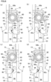
- Each of FIGs. 6(a) and 6(b) shows a later-described hook unit 62 viewed from one side in the extending direction.
- Each of FIGs. 6(c) and 6(d) shows a later-described hook unit 63 viewed from the other side in the extending direction.
- the up-down direction of the sheet of each of FIGs. 6(a) to 6(d) is in parallel to the height direction.
- FIGs. 7(a) and 7(b) shows the hook units 62 and 63 viewed in the width direction (base longitudinal direction).
- a reference position is set at a position where a later-described warping unit 61C (see FIG. 4(b) and FIG. 5 ) is provided in the extending direction.
- the left side of the warping unit 61C in the sheet is defined as one side in the extending direction
- the right side of the warping unit 61C in the sheet is defined as the other side in the extending direction.
- the following describes only a structure (to be more specific, a structure shown in a right part of the sheet of FIG. 4(a) ) provided for heating one of two yarns Y in the first heater 13.
- This structure provided for heating one of two yarns Y is the same as a structure provided for heating the other of two yarns Y. Therefore, the explanation of the structure provided for heating the other of two yarns Y is omitted.
- a yarn contacted member 43 of the present embodiment is structured as described below.
- the yarn contacted member 43 extends to be substantially linear (e.g., see two-dot chain lines of FIG. 5 ).
- a yarn contacted surface 57 also extends to be substantially linear in a direction in which the yarn contacted member 43 extends.
- the yarn contacted member 43 is attachable to and detachable from the heating unit 41 as described later.
- the first heater 13 further includes an elastic deformation holding unit 60 configured to hold the yarn contacted member 43 so that the yarn contacted member 43 is attachable to and detachable from the heating unit 41.
- the elastic deformation holding unit 60 is configured to hold the yarn contacted member 43, which is attached to the heating unit 41, while elastically deforming the yarn contacted member 43 (as described later).
- the elastic deformation holding unit 60 includes, e.g., the warping units 61 (see FIG. 4(b) and FIG. 5 ), the hook unit 62 (see FIG. 4(a) , FIG. 6(a) , FIG. 6(b) , and FIG. 7(a) ), and the hook unit 63 (see FIG.
- the warping units 61, the hook unit 62, and the hook unit 63 are attached to the heating unit 41.
- the warping units 61, the hook unit 62, and the hook unit 63 are configured to elastically deform the yarn contacted member 43 and to keep the yarn contacted member 43 elastically deformed.
- the warping units 61 are in contact with some parts of the yarn contacted member 43 in the extending direction, and configured to regulate the movement of the yarn contacted member 43 toward the other side (opposite side from the working space S) in the height direction.
- the warping units 61 are provided on the other side (opposite side from the working space S) in the height direction as compared to the yarn contacted member 43.
- Each warping unit 61 is a bolt-shaped member extending in the width direction as shown in, e.g., FIG. 4(b) .
- Each warping unit 61 may be, e.g., a known full-dog point set bolt.
- a direction in which each warping unit 61 extends will be referred to as a bolt axial direction.
- Each warping unit 61 has, e.g., a head 71, a male screw portion 72, and a leading end portion 73.
- the head 71 is provided on the most base end side in the bolt axial direction of each warping unit 61.
- the male screw portion 72 is a part of each warping unit 61, which is provided immediately on the leading end side of the head 71 in the bolt axial direction and at which a male screw is formed.
- the male screw portion 72 is screwed to, e.g., a female screw portion formed at a second heating member 55. With this arrangement, each warping unit 61 is fixed to the second heating member 55 of the heating unit 41.
- the leading end portion 73 is a part of each warping unit 61, which is provided immediately on the leading end side of the male screw portion 72 in the bolt axial direction and at which no screw is formed.
- the leading end portion 73 is provided to overlap, e.g., a housing space 56 in the width direction. With this arrangement, the leading end portion 73 is able to make contact with a part of the yarn contacted member 43 in the extending direction.
- the warping unit 61C (see FIG. 4(b) and FIG. 5 ) provided substantially at the center of the first heater 13 in the extending direction is in contact with a first part 43f (see FIG. 4(b) ; indicated by broken lines in FIG. 5 ) of the yarn contacted member 43.
- the first part 43f of the yarn contacted member 43 is provided at the center (predetermined position of the present invention) of the yarn contacted member 43 in the extending direction.
- the warping units 61 regulate the movement of some parts of the yarn contacted member 43 which include the first part 43f toward the other side in the height direction (i.e., some parts of the yarn contacted member 43 in the extending direction: hereinafter, these parts will be simply referred to as inner parts for the sake of convenience).
- each warping unit 61 is fixed to the second heating member 55 as described above.
- the disclosure is not limited to this.
- Each warping unit 61 may be fixed to, e.g., a first heating member 54.
- each warping unit 61 is spaced apart from one another in the extending direction.
- the positions of each two adjacent warping units 61 are slightly different in the height direction so that the cross sectional curve 59 of a yarn contacted surface 57 has a predetermined curvature.
- each warping unit 61 is immovable with respect to the heating unit 41.
- the hook unit 62 is configured to regulate the movement of a second part 43s (see the hatched part in FIG. 7(a) ) of the yarn contacted member 43 toward one side (the working space S side) in the height direction.
- the second part 43s of the yarn contacted member 43 is provided on one side in the extending direction as compared to the first part 43f of the yarn contacted member 43.
- the second part 43s is provided at an end portion of the yarn contacted member 43 on one side in the extending direction.
- the hook unit 62 is configured to hold the yarn contacted member 43 so that the yarn contacted member 43 is attachable to and detachable from the heating unit 41.
- the hook unit 62 includes a swing member 81, a swing axis 82 extending along the extending direction, and a torsion coil spring 83. As the swing member 81 swings about the swing axis 82, the movement of the second part 43s toward one side in the height direction is regulated or allowed.
- the swing member 81 (see FIG. 4(a) , FIGs. 6(a) and 6(b) , and FIG. 7(a) ) is swingably attached to the heating unit 41 through the swing axis 82.
- the swing member 81 is formed by, e.g., processing a sheet metal.
- the swing member 81 includes a base portion 84, a stopper 85, and a handle 86.
- the base portion 84 is a plate provided with an insertion hole (not illustrated) into which the swing axis 82 is inserted.
- the stopper 85 is a plate extending at least radially outward of the swing axis 82 from the base portion 84.
- the stopper 85 has a claw-shaped contact portion 85b (a second force portion and a second regulatory portion of the present invention) provided with a contact surface 85a which is able to make contact with one end portion of the second part 43s of the yarn contacted member 43 in the height direction. In the height direction, this end portion of the second part 43s is provided on one side in the height direction as compared to its the other end.
- the contact surface 85a is able to make contact with one end of one regulatory wall 58 in the height direction. In the height direction, this end of the regulatory wall 58 is provided on one side in the height direction as compared to its the other end.
- the contact portion 85b is movable between an overlapping position (see FIG. 6(a) ) which overlaps the yarn contacted member 43 when viewed in the height direction and a retracted position (see FIG. 6(b) ) which does not overlap the yarn contacted member 43 when viewed in the height direction. Strictly speaking, the contact portion 85b (the hatched part in FIG. 6(a) ) extends from the contact surface 85a toward one side in the height direction when the contact portion 85b is at the overlapping position (i.e., when the contact surface 85a is in contact with the second part 43s).
- the stopper 85 makes contact with a part of one end face of the yarn contacted member 43 in the width direction so that swinging of the stopper 85 is regulated by the yarn contacted member 43.
- the contact surface 85a is provided on the other side in the height direction as compared to an end of the first part 43f on one side in the height direction.
- an inclined surface 85c (see FIG. 6(a) ) oriented at least toward one side in the height direction is provided. In the height direction, this end portion of the contact portion 85b is provided on one side in the height direction as compared to the other end portion of the contact portion 85b.
- the inclined surface 85c overlaps a part of the housing space 56 in the width direction. When viewed in the extending direction, the inclined surface 85c is inclined, e.g., toward the center of the housing space 56 in the width direction and toward the other side in the height direction.
- the handle 86 extends from, e.g., the stopper 85 toward one side in the extending direction. An operator can pinch and use the handle 86 by hand.
- the handle 86 is provided with, e.g., a fitting hole 86a to which a first arm 83a (described later) of the torsion coil spring 83 is fitted.
- the swing axis 82 is fixed to an end portion of the heating unit 41 on one side in the extending direction.
- the swing axis 82 is, e.g., provided on the other side (opposite side from the working space S) in the height direction as compared to the housing space 56.
- the swing axis 82 is configured to swingably support the swing member 81.
- the axial direction of the swing axis 82 is substantially in parallel to, e.g., the extending direction.
- the torsion coil spring 83 is attached to the swing axis 82.
- the torsion coil spring 83 is configured to bias the swing member 81 (including the contact portion 85b) so that the swing member 81 moves from the retracted position to the overlapping position.
- the torsion coil spring 83 is attached to the swing axis 82.
- the first arm 83a is formed.
- a second arm 83b is formed.
- the first arm 83a is fitted to, e.g., the fitting hole 86a of the handle 86 and swingable with the swing member 81.
- the second arm 83b is fixed to, e.g., the cover member 51 not to be swingable about the swing axis 82.
- the torsion coil spring 83 is included in a biasing portion of the present invention.
- the hook unit 63 is configured to regulate the movement of a third part 43t (see the hatched part in FIG. 7(b) ) of the yarn contacted member 43 toward one side (the working space S side) in the height direction.
- the third part 43t is provided on the other side in the extending direction as compared to the first part 43f of the yarn contacted member 43.
- the third part 43t is provided at an end portion of the yarn contacted member 43 on the other side in the extending direction.
- the end portion of the yarn contacted member 43 on the other side in the extending direction indicates, e.g., a part of (or all of) an area ranging from an end face of the yarn contacted member 43 on the other side in the extending direction to a part which is distant from the end face by 10 mm.
- the hook unit 63 is configured to hold the yarn contacted member 43 so that the yarn contacted member 43 is attachable to and detachable from the heating unit 41.
- the hook units 62 and 63 are provided in a symmetrical manner when viewed in the width direction. Therefore, the hook unit 63 is not detailed.
- the hook unit 63 includes a swing member 91, a swing axis 92 extending along, e.g., the extending direction, and a torsion coil spring 93.
- the swing member 91 corresponds to the swing member 81.
- the swing member 91 is swingably attached to the heating unit 41 through the swing axis 92.
- the swing member 91 includes a base portion 94, a stopper 95, and a handle 96.
- the stopper 95 has a claw-shaped contact portion 95b (a third force portion and a third regulatory portion of the present invention) provided with a contact surface 95a which is able to make contact with one end portion of the third part 43t of the yarn contacted member 43 in the height direction. In the height direction, this end portion of the third part 43t is provided on one side in the height direction as compared to its the other end portion.
- the contact portion 95b is movable between an overlapping position (see FIG.
- the contact portion 95b (the hatched part in FIG. 6(c) ) extends from the contact surface 95a toward one side in the height direction when the contact portion 95b is at the overlapping position (i.e., when the contact surface 95a is in contact with the third part 43t).
- the contact surface 95a is provided on the other side in the height direction as compared to the end of the first part 43f on one side in the height direction.
- an inclined surface 95c (see FIG. 6(c) ) oriented at least toward one side in the height direction is provided on one side in the height direction as compared to the contact surface 95a.
- the inclined surface 95c overlaps a part of the housing space 56 in the width direction.
- the inclined surface 95c is inclined, e.g., toward the center of the housing space 56 in the width direction and toward the other side in the height direction.
- the handle 96 is provided with, e.g., a fitting hole 96a to which a first arm 93a (described later) of the torsion coil spring 93 is fitted.
- the swing axis 92 is fixed to an end portion of the heating unit 41 on the other side in the extending direction.
- the swing axis 92 is, e.g., provided on the other side (opposite side from the working space S) in the height direction as compared to the housing space 56.
- the axial direction of the swing axis 92 is substantially in parallel to, e.g., the extending direction.
- the torsion coil spring 93 is configured to bias the swing member 91 (including the contact portion 95b) so that the swing member 91 moves from the retracted position to the overlapping position.
- the torsion coil spring 93 is attached to the swing axis 92. At one end portion of the torsion coil spring 93, the first arm 93a is formed.
- a second arm 93b is formed at the other end portion of the torsion coil spring 93.
- the first arm 93a is fitted to, e.g., the fitting hole 96a of the handle 96 and swingable with the swing member 91.
- the second arm 93b is fixed to, e.g., the cover member 51.
- the torsion coil spring 93 is included in the biasing portion of the present invention, as the torsion coil spring 83 is.
- each of the contact portion 85b of the above-described swing member 81 and the contact portion 95b of the above-described swing member 91 is at the overlapping position (see FIGs. 6(a) and 6(c) ). Furthermore, the torsion coil spring 83 biases the swing member 81 toward the overlapping position (toward the left side of the sheet of FIG.
- the torsion coil spring 93 biases the swing member 91 toward the overlapping position (toward the right side of the sheet of FIG. 6(c) ). Because of this, the yarn contacted member 43 is prevented from dropping from the heating unit 41.
- the yarn contacted member 43 When viewed in the width direction, the yarn contacted member 43 is attached to the heating unit 41 while being elastically deformed as indicated by solid lines in FIG. 5 on account of the above-described arrangements of the warping units 61 and hook units 62 and 63.
- the yarn contacted member 43 is warped so that the both end portions of the yarn contacted member 43 in the extending direction are on the other side (opposite side from the working space S) in the height direction as compared to the remaining parts of the yarn contacted member 43.
- the center of the first heater 13 in the extending direction and its surrounding portions are provided on one side (the working space S side) in the height direction of the both end portions of the yarn contacted member 43.
- the above-described inner parts of the yarn contacted member 43 in the extending direction are about to be moved toward the other side in the height direction on account of elastic restoring force.
- the movement of some parts in contact with the respective warping units 61 i.e., the inner parts of the yarn contacted member 43 in the extending direction which include the first part 43f
- the warping units 61 apply a force toward one side in the height direction (as indicated by arrows directed to the lower side of the sheet of FIG. 5 ) to these inner parts of the yarn contacted member 43 in the extending direction on account of the law of action and reaction.
- the second part 43s and third part 43t of the yarn contacted member 43 are about to be moved toward one side in the height direction on account of the elastic restoring force.
- the movement of the second part 43s toward one side in the height direction is regulated by the contact portion 85b of the hook unit 62
- the movement of the third part 43t toward one side in the height direction is regulated by the contact portion 95b of the hook unit 63.
- the hook units 62 and 63 apply a force toward the other side in the height direction (as indicated by arrows directed to the upper side of the sheet of FIG. 5 ) to the second part 43s and the third part 43t on account of the law of action and reaction.
- the yarn contacted member 43 is attached to the heating unit 41 while being elastically deformed.
- the cross sectional curve 59 (see FIGs. 3(b) ) in a cross section orthogonal to the width direction of a yarn contacted surface 57 has a predetermined curvature.
- the curvature radius of the cross sectional curve 59 is within a range of, e.g., 15 to 20 meters at any part of the cross sectional curve 59.
- the curvature radius of the cross sectional curve 59 may be constant at any part of the cross sectional curve 59.
- the disclosure is not limited to this.
- the following will describe a method of attaching and detaching the yarn contacted member 43 to and from the heating unit 41.
- the following describes a method of detaching the yarn contacted member 43 from the heating unit 41.
- the movement of the both end portions of the yarn contacted member 43 in the extending direction toward one side in the height direction is allowed in such a way that the operator operates the swing members 81 and 91 of the elastic deformation holding unit 60 to move (swing) each of the contact portions 85b and 95b from the overlapping position to the retracted position.
- This allows the operator to detach the yarn contacted member 43 from the heating unit 41 by manually moving the yarn contacted member 43 in the housing space 56 toward one side in the height direction (causing the yarn contacted member 43 to pass through the housing space 56).
- the operator may instantly detach the entire yarn contacted member 43 from the heating unit 41 by moving each of the contact portions 85b and 95b from the overlapping position to the retracted position substantially at the same time.
- the operator may detach the entire yarn contacted member 43 from the heating unit 41 after moving one of the contact portions 85b and 95b to the retracted position, detaching a part of the yarn contacted member 43 from the heating unit 41, and moving the other of the contact portions 85b and 95b to the retracted position.
- the yarn contacted member 43 is restored in shape (to be substantially linear: as indicated by two-dot chain lines in FIG. 5 ) on account of the elastic restoring force.
- the following describes a method of attaching the yarn contacted member 43 to the heating unit 41.
- the operator inserts the yarn contacted member 43 into the housing space 56 by hand. Subsequently, the operator moves the both end portions of the yarn contacted member 43 in the extending direction toward the other side in the height direction while pressing the above-described inner parts of the yarn contacted member 43 in the extending direction onto the warping units 61. This starts the elastic deformation of the yarn contacted member 43.
- the operator then further moves the both end portions of the yarn contacted member 43 in the extending direction toward the other side in the height direction while pressing the yarn contacted member 43 onto the inclined surfaces 85c and 95c.
- the yarn contacted member 43 is elastically deformed by the elastic deformation holding unit 60 and attached to the heating unit 41 so that the cross sectional curve 59 of the yarn contacted surface 57 has a predetermined curvature.
- the yarn contacted surface 57 has a desired shape only in such a way that the yarn contacted member 43 is elastically deformed.
- the production cost of the yarn contacted member 43 is reduced as compared to a case where a yarn contacted member (not illustrated) is processed in advance based on the specifications of the first heater 13. It is therefore possible to achieve the reduction in production cost of the yarn contacted member 43 applied to the first heater 13.
- the yarn contacted member 43 is detachable from the heating unit 41 at the time of cleaning. It is therefore possible to improve the work efficiency in cleaning of the yarn contacted member 43, irrespective of the position of the first heater 13.
- the yarn contacted member 43 may be attached to and detached from the heating unit 41 by, e.g., being inserted into and pulled out from the heating unit 41 in the extending direction.
- a long space provided for the attachment and detachment of the yarn contacted member 43 is required at a position adjacent to the first heater 13 in the extending direction. This puts a large limit on the layout of the first heater 13 and its surroundings. Assume that such a long space at the position adjacent to the first heater 13 in the extending direction is secured.
- a regulatory member such as the twist-stopping guide 12 (see FIG. 1 ) configured to define a yarn path is provided in this space, the following problems may occur.
- the yarn contacted member 43 is attachable to and detachable from the heating unit 41 by moving the yarn contacted member 43 in the height direction.
- a force toward one side in the height direction is applied to a part of the yarn contacted member 43 in the extending direction, and a force toward the other side in the height direction is applied to the both end portions of the yarn contacted member 43 in the extending direction.
- the force toward one side in the height direction is applied to the first part 43f on account of the law of action and reaction in such a way that one warping unit 61 regulates the movement of the first part 43f toward the other side in the height direction.
- the force toward the other side in the height direction is applied to the second part 43s and the third part 43t on account of the law of action and reaction in such a way that the contact portions 85b and 95b regulate the movement of the second part 43s and third part 43t toward one side in the height direction. It is therefore possible to elastically deform the yarn contacted member 43 with a simple structure.
- Each of the contact portions 85b and 95b is movable between the retracted position and the overlapping position.
- the yarn contacted member 43 is attached to the heating unit 41 in such a simple way that (i) each of the contact portions 85b and 95b is temporarily moved to the retracted position and then (ii) each of the contact portions 85b and 95b is moved back to the overlapping position while the yarn contacted member 43 is warped.
- the yarn contacted member 43 is attached to the heating member 41, the yarn contacted member 43 is detached from the heating unit 41 in such a simple way that each of the contact portions 85b and 95b is temporarily moved to the retracted position.
- the contact portion 85b is biased from the retracted position toward the overlapping position by the torsion coil spring 83.
- the contact portion 95b is biased from the retracted position toward the overlapping position by the torsion coil spring 93. This suppresses each of the contact portions 85b and 95b from being unintentionally moved from the overlapping position to the retracted position.
- the swing members 81 and 91 i.e., the contact portions 85b and 95b
- the swing members 81 and 91 are swingably supported by the respective swing axes 82 and 92. It is therefore possible to downsize a space required for the movement of the contact portions 85b and 95b.
Landscapes
- Engineering & Computer Science (AREA)
- Textile Engineering (AREA)
- Mechanical Engineering (AREA)
- Yarns And Mechanical Finishing Of Yarns Or Ropes (AREA)
- Resistance Heating (AREA)
Abstract
Description
- The present invention relates to a heater configured to heat a yarn.
- Patent Literature 1 (
Japanese Laid-Open Patent Publication No. 2002-194631 - The specifications (to be more specific, a suitable curvature of a yarn path formed by the yarn contacted surface) of the above-described heater may vary mainly because of the layout of the textile machine forming the yarn path. Traditionally, a yarn contacted member is processed in advance based on the specifications of a heater so that a yarn path has a suitable curvature. Therefore, production cost is high.
- An object of the present invention is to achieve the reduction in production cost of a yarn contacted member applied to a heater.
- A heater according to a first aspect of the invention is configured to heat a running yarn, and includes: a heat source; a heating unit which extends in a predetermined extending direction and which is heated by the heat source; a yarn contacted member which has a yarn contacted surface, which extends at least in the extending direction, and which is heated by the heating unit, the yarn making contact with the yarn contacted surface; and an attaching portion which includes the heating unit and to which the yarn contacted member is attached. In this regard, the yarn contacted surface extends at least in the extending direction and is oriented at least to one side in a predetermined height direction orthogonal to the extending direction. This heater further includes an elastic deformation holding unit configured to hold the yarn contacted member attached to the attaching portion while elastically deforming the yarn contacted member viewed in a width direction orthogonal to the extending direction and the height direction. When the yarn contacted member is elastically deformed and held by the elastic deformation holding unit, a cross sectional curve in a cross section orthogonal to the width direction of the yarn contacted member has a predetermined curvature.
- According to this aspect, the cross sectional curve of the yarn contacted surface has a predetermined curvature in such a way that the elastic deformation holding unit holds the yarn contacted member which is attached to the attaching portion while being elastically deformed. In other words, even when the yarn contacted member is produced to linearly extend and is attached to the heater, the yarn contacted surface has a desired shape only in such a way that the yarn contacted member is elastically deformed. With this arrangement, the production cost of the yarn contacted member is reduced as compared to a case where the yarn contacted member is processed based on the specifications of the heater. It is therefore possible to achieve the reduction in production cost of the yarn contacted member applied to the heater.
- According to a second aspect of the invention, the heater of the first aspect is arranged such that the elastic deformation holding unit is configured to hold the yarn contacted member so that the yarn contacted member is attachable to and detachable from the attaching portion.
- Typically, a member with which the running yarn makes contact is cleaned according to need. In this regard, the heater may be provided at a position higher than the stature of an operator who cleans the member. Therefore, when the yarn contacted member cannot be detached from the attaching portion, the cleaning of the member may be difficult depending on the position of the heater. The present invention makes it possible to detach the yarn contacted member from the attaching portion at the time of cleaning. It is therefore possible to improve the work efficiency in cleaning of the yarn contacted member, irrespective of the position of the heater.
- According to a third aspect of the invention, the heater of the second aspect is arranged such that an attachment-detachment path through which the yarn contacted member is able to pass in the height direction at the time of attachment and detachment of the yarn contacted member is formed in the attaching portion.
- For example, the yarn contacted member may be attached to and detached from the attaching portion by being inserted in and pulled out from the attaching portion in the extending direction. In this case, however, a long space provided for the attachment and detachment of the yarn contacted member is required at a position adjacent to the heater in the extending direction. This puts a large limit on the layout of the heater and its surroundings. According to this aspect, the yarn contacted member is attachable to and detachable from the attaching portion by moving the yarn contacted member in the height direction. In this case, the above-described long space at the position adjacent to the heater in the extending direction is not required. It is therefore possible to suppress the occurrence of disadvantages such as the limit on the layout of the heater and its surroundings.
- According to a fourth aspect of the invention, the heater of any one of the first to third aspects is arranged such that the elastic deformation holding unit includes: a first force portion configured to apply the force toward one side in the height direction to a first part of the yarn contacted member attached to the attaching portion, the first part being at a predetermined position in the extending direction; a second force portion configured to apply the force toward the other side in the height direction to a second part of the yarn contacted member attached to the attaching portion, the second part being provided on one side in the extending direction as compared to the first part; and a third force portion configured to apply the force toward the other side in the height direction to a third part of the yarn contacted member attached to the attaching portion, the third part being provided on the other side in the extending direction as compared to the first part.
- According to this aspect, the force toward one side in the height direction is applied to a part of the yarn contacted member in the extending direction. Relative to this part, one part of the yarn contacted member is provided on one side in the extending direction and another part of the yarn contacted member is provided on the other side in the extending direction. The force toward the other side in the height direction is applied to these two parts. With this arrangement, the yarn contacted member is warped. It is therefore possible to elastically deform the yarn contacted member with a simple structure.
- According to a fifth aspect of the invention, the heater of the fourth aspect is arranged such that the first force portion includes a first regulatory portion which is provided on the other side in the height direction as compared to the first part and which is configured to regulate the movement of the first part toward the other side in the height direction, the second force portion includes a second regulatory portion which is provided on one side in the height direction as compared to the second part and which is configured to regulate the movement of the second part toward one side in the height direction, and the third force portion includes a third regulatory portion which is provided on one side in the height direction as compared to the third part and which is configured to regulate the movement of the third part toward one side in the height direction.
- According to this aspect, the force toward one side in the height direction is applied to the first part on account of the law of action and reaction in such a way that the first regulatory portion regulates the movement of the first part toward the other side in the height direction. The force toward the other side in the height direction is applied to the second part and the third part on account of the law of action and reaction in such a way that the second regulatory portion and the third regulatory portion regulate the movement of the second part and third part toward one side in the height direction. It is therefore possible to elastically deform the yarn contacted member with a simple structure.
- According to a sixth aspect of the invention, the heater of the fifth aspect is arranged such that, when each of the second regulatory portion and the third regulatory portion is viewed in the height direction, the each of the second regulatory portion and the third regulatory portion is movable between a retracted position which does not overlap the yarn contacted member and an overlapping position which overlaps the yarn contacted member.
- According to this aspect, when the yarn contacted member is to be attached to the attaching portion, the yarn contacted member is attached to the attaching portion in such a simple way that (i) the each of the second regulatory portion and the third regulatory portion is temporarily moved to the retracted position and then (ii) the each of the second regulatory portion and the third regulatory portion is moved back to the overlapping position while the yarn contacted member is warped. When the yarn contacted member is attachable to and detachable from the attaching portion, the yarn contacted member is detached from the attaching portion in such a simple way that the each of the second regulatory portion and the third regulatory portion is temporarily moved to the retracted position.
- According to a seventh aspect of the invention, the heater of the sixth aspect further includes a biasing portion configured to bias the each of the second regulatory portion and the third regulatory portion from the retracted position to the overlapping position.
- This suppresses the each of the second regulatory portion and the third regulatory portion from being unintentionally moved from the overlapping position to the retracted position.
- According to an eighth aspect of the invention, the heater of the sixth or seventh aspect further includes a swing axis configured to swingably support the each of the second regulatory portion and the third regulatory portion.
- The second regulatory portion and the third regulatory portion may be movable in a parallel manner. In this case, however, a large space is required for the movement of the second regulatory portion and the third regulatory portion. According to this aspect, for example, when the yarn contacted member is to be attached to the attaching portion in the production of the heater (or when the yarn contacted member which is attachable to and detachable from the attaching portion is to be detached from the attaching portion), a space required for the movement of the second regulatory portion and the third regulatory portion is downsized.
- According to a ninth aspect of the invention, the heater of any one of the fifth to eighth aspects is arranged such that the position of at least one of the first regulatory portion, the second regulatory portion, and the third regulatory portion is changeable with respect to the attaching portion in at least one of the extending direction and the height direction.
- According to this aspect, the curvature of the cross sectional curve of the yarn contacted surface is adjustable according to need even after the heater is set.
-
-
FIG. 1 is a profile of a false-twist texturing machine including a first heater of an embodiment. -
FIG. 2 is a schematic diagram of the false-twist texturing machine, expanded along paths of yarns. - Each of
FIGs. 3(a) to 3(e) shows the structure of the first heater. - Each of
FIGs. 4(a) and 4(b) shows the structure of the first heater. -
FIG. 5 shows a warping unit. - Each of
FIGs. 6(a) to 6(d) shows a hook unit viewed in an extending direction. - Each of
FIGs. 7(a) and 7(b) shows the hook unit viewed in a width direction. - The following will describe an embodiment of the present invention. Hereinafter, the direction perpendicular to the sheet of
FIG. 1 will be referred to as a base longitudinal direction. Hereinafter, the left-right direction of the sheet ofFIG. 1 will be referred to as a base width direction. Hereinafter, the direction orthogonal to the base longitudinal direction and the base width direction will be referred to as an up-down direction (vertical direction) in which the gravity acts. - The following will describe the overall structure of a false-
twist texturing machine 1 including a first heater 13 (heater of the present invention: details thereof will be described later) of the present embodiment, with reference toFIG. 1 andFIG. 2 .FIG. 1 is a profile of the false-twist texturing machine 1.FIG. 2 is a schematic diagram of the false-twist texturing machine 1, expanded along paths of yarns Y (yarn paths). - The false-
twist texturing machine 1 is able to perform false twisting of yarns Y (to false-twist yarns Y) made of synthetic fibers (e.g., polyester). Each yarn Y is, e.g., a multi-filament yarn formed of filaments. Alternatively, each yarn Y may be formed of a single filament. The false-twist texturing machine 1 includes ayarn supplying unit 2, aprocessing unit 3, and a windingunit 4. Theyarn supplying unit 2 is able to supply yarns Y. Theprocessing unit 3 is configured to pull out the yarns Y from theyarn supplying unit 2, and to false-twist the yarns Y. The windingunit 4 is configured to wind the yarns Y processed by theprocessing unit 3 onto winding bobbins Bw. Components of theyarn supplying unit 2, theprocessing unit 3, and the windingunit 4 are aligned to form plural lines (seeFIG. 2 ) in the base longitudinal direction. The base longitudinal direction is a direction orthogonal to a running plane (plane ofFIG. 1 ) of the yarns Y. The running plane of the yarns Y is formed of the yarn paths extending from theyarn supplying unit 2 to the windingunit 4 through theprocessing unit 3. - The
yarn supplying unit 2 includes a creel stand 7 retaining yarn supply packages Ps, and is configured to supply the yarns Y to theprocessing unit 3. Theprocessing unit 3 is configured to pull out the yarns Y from theyarn supplying unit 2, and to process the yarns Y. In theprocessing unit 3, the following members are provided in this order from the upstream side in a yarn running direction: eachfirst feed roller 11; each twist-stoppingguide 12; eachfirst heater 13; each cooler 14; each false-twistingdevice 15; eachsecond feed roller 16; each interlacingdevice 17; eachthird feed roller 18; asecond heater 19; and eachfourth feed roller 20. The windingunit 4 includes windingdevices 21. Each windingdevice 21 is configured to wind a yarn Y for which the false twisting has been performed by theprocessing unit 3 onto a winding bobbin Bw, and to form a wound package Pw. - The false-
twist texturing machine 1 includes amain frame 8 and a windingbase 9 which are spaced apart from each other in the base width direction. Themain frame 8 and the windingbase 9 are substantially identical in length in the base longitudinal direction. Themain frame 8 and the windingbase 9 oppose each other in the base width direction. The false-twist texturing machine 1 includes units termed spans each of which includes a pair of themain frame 8 and the windingbase 9. In one span, each device is placed so that the false twisting is simultaneously performable for the yarns Y running while being aligned in the base longitudinal direction. In the false-twist texturing machine 1, the spans are placed in a left-right symmetrical manner to the sheet, with a center line C of the base width direction of themain frame 8 as a symmetry axis. (That is, themain frame 8 is shared between the left span and the right span.) The spans are aligned in the base longitudinal direction. - The following will describe the structure of the
processing unit 3 with reference toFIG. 1 andFIG. 2 . Eachfirst feed roller 11 is configured to unwind a yarn Y from one yarn supply package Ps attached to theyarn supplying unit 2, and to send the yarn Y to onefirst heater 13. As shown inFIG. 2 , eachfirst feed roller 11 is configured to send, e.g., a single yarn Y to thefirst heater 13. Alternatively, eachfirst feed roller 11 may be able to send plural adjacent yarns Y to the downstream side in the yarn running direction. Each twist-stoppingguide 12 prevents twisting, which is applied to a yarn Y by one later-described false-twistingdevice 15, from being propagated to the upstream of each twist-stoppingguide 12 in the yarn running direction. - Each
first heater 13 is configured to increase the temperature of yarns Y sent from somefirst feed rollers 11 to a predetermined processing temperature. As shown inFIG. 2 , eachfirst heater 13 is able to heat, e.g., two yarns Y. Below thefirst heater 13, there is a working space S (seeFIG. 1 ) provided for an operator to perform yarn threading, etc. Eachfirst heater 13 will be detailed later. - Each cooler 14 is configured to cool a yarn Y heated by one
first heater 13. As shown inFIG. 2 , each cooler 14 is configured to cool, e.g., a single yarn Y. Alternatively, the cooler 14 may be able to simultaneously cool plural yarns Y. Each false-twistingdevice 15 is provided downstream of one cooler 14 in the yarn running direction, and configured to twist a yarn Y. Each false-twistingdevice 15 is, e.g., a so-called disc-friction false-twisting device. However, the disclosure is not limited to this. Eachsecond feed roller 16 is configured to send a yarn Y processed by one false-twistingdevice 15 to oneinterlacing device 17. The conveyance speed of conveying the yarn Y by eachsecond feed roller 16 is higher than the conveyance speed of conveying the yarn Y by eachfirst feed roller 11. Because of this, the yarn Y is therefore drawn and false-twisted between eachfirst feed roller 11 and eachsecond feed roller 16. - Each interlacing
device 17 is configured to interlace a yarn Y. Each interlacingdevice 17 has, e.g., a known interlace nozzle configured to interlace the yarn Y by means of an airflow. - Each
third feed roller 18 is configured to send, to thesecond heater 19, a yarn Y running on the downstream side of one interlacingdevice 17 in the yarn running direction. As shown inFIG. 2 , eachthird feed roller 18 is configured to send, e.g., a single yarn Y to thesecond heater 19. Alternatively, eachthird feed roller 18 may be able to send plural adjacent yarns Y to the downstream side in the yarn running direction. The conveyance speed of conveying the yarn Y by eachthird feed roller 18 is lower than the conveyance speed of conveying the yarn Y by eachsecond feed roller 16. The yarn Y is therefore relaxed between eachsecond feed roller 16 and eachthird feed roller 18. Thesecond heater 19 is configured to heat yarns Y sent from somethird feed rollers 18. Thesecond heater 19 extends along the vertical direction, and is provided for each of the spans. Eachfourth feed roller 20 is configured to send a yarn Y heated by thesecond heater 19 to one windingdevice 21. As shown inFIG. 2 , eachfourth feed roller 20 is able to send, e.g., a single yarn Y to the windingdevice 21. Alternatively, eachfourth feed roller 20 may be able to send plural adjacent yarns Y to the downstream side in the yarn running direction. The conveyance speed of conveying the yarn Y by eachfourth feed roller 20 is lower than the conveyance speed of conveying the yarn Y by eachthird feed roller 18. The yarn Y is therefore relaxed between eachthird feed roller 18 and eachfourth feed roller 20. - In the
processing unit 3 arranged as described above, each yarn Y drawn between thefirst feed roller 11 and thesecond feed roller 16 is twisted by the false-twistingdevice 15. The twist formed by the false-twistingdevice 15 propagates to the twist-stoppingguide 12, but does not propagate to the upstream side of the twist-stoppingguide 12 in the yarn running direction. The yarn Y which is twisted and drawn is heated by thefirst heater 13 and thermally set. After that, the yarn Y is cooled by the cooler 14. The yarn Y is untwisted on the downstream side of the false-twistingdevice 15 in the yarn running direction. However, the yarn Y is maintained to be wavy in shape on account of the thermal setting described above (i.e., crimp contraction of the yarn Y is maintained). - After being false-twisted, the yarn Y is interlaced by the interlacing
device 17 while being relaxed between thesecond feed roller 16 and thethird feed roller 18. The yarn Y is then guided to the downstream side in the yarn running direction. Furthermore, the yarn Y is thermally set by thesecond heater 19 while being relaxed between thethird feed roller 18 and thefourth feed roller 20. Finally, the yarn Y which is sent from thefourth feed roller 20 is wound by the windingdevice 21. - The following will describe the structure of the winding
unit 4 with reference toFIG. 2 . The windingunit 4 includes plural windingdevices 21. Each windingdevice 21 is able to wind one yarn Y onto one winding bobbin Bw. The windingdevice 21 includes afulcrum guide 31, atraverse unit 32, and acradle 33. Thefulcrum guide 31 is a guide functioning as a fulcrum when the yarn Y is traversed. Thetraverse unit 32 is able to traverse the yarn Y by means of atraverse guide 34. Thecradle 33 is configured to rotatably support the winding bobbin Bw. Acontact roller 35 is provided in the vicinity of thecradle 33. Thecontact roller 35 is configured to make contact with a surface of one wound package Pw so as to apply a contact pressure to the surface of the wound package Pw. In the windingunit 4 arranged as above, the yarn Y sent from the above-describedfourth feed roller 20 is wound onto the winding bobbin Bw by the windingdevice 21 so that the wound package Pw is formed. - The following will detail each
first heater 13 with reference toFIGs. 3(a) to 3(e) andFIGs. 4(a) and 4(b) .FIG. 3(a) shows onefirst heater 13 viewed in the base longitudinal direction.FIG. 3(a) illustrates thefirst heater 13 extending along the left-right direction of the sheet ofFIG. 3 (a). FIG. 3(b) is a cross section of thefirst heater 13, which is taken along a direction orthogonal to the base longitudinal direction.FIG. 3(b) illustrates a yarn contacted surface 57 (described later) of a yarn contacted member 43 (described later).FIG. 3(c) is an enlarged view of a left end part ofFIG. 3(b). FIG. 3(d) is an enlarged view of one end of the yarn contactedmember 43 of thefirst heater 13 in an extending direction.FIG. 3(e) is a cross section taken along a line III(e)-III(e) inFIG. 3(d) .FIG. 4(a) is a view ofFIG. 3(a) viewed along an arrow IV(a) inFIG. 3(a) .FIG. 4(b) is a cross section taken along a line IV(b)-IV(b) inFIG. 3(a) . - For the sake of convenience, hereinafter, the left-right direction of the sheet of each of
FIGs. 3(a) and 3(b) will be referred to as the extending direction in which thefirst heater 13 extends. In this regard, the extending direction is orthogonal to the base longitudinal direction. The left side of the sheet of each ofFIGs. 3(a) and 3(b) is defined as one side in the extending direction, and the right side of the sheet of each ofFIGs. 3(a) and 3(b) is defined as the other side in the extending direction. Hereinafter, the direction orthogonal to the base longitudinal direction and the extending direction will be referred to as a height direction. The lower side of the sheet of each ofFIGs. 3(a) and 3(b) andFIGs. 4(a) and 4(b) is defined as one side in the height direction, and the upper side of the sheet of each ofFIGs. 3(a) and 3(b) andFIGs. 4(a) and 4(b) is defined as the other side in the height direction. Although not illustrated, these descriptions and definitions of the directions are also applied toFIGs. 3(c) to 3(e) ,FIGs. 6(a) to 6(d) , andFIGs. 7(a) and 7(b) described later. In thefirst heater 13, specifically, one side in the height direction is close to the working space S (seeFIG. 1 ) as compared to the other side in the height direction. Hereinafter, one side in the height direction may be referred to as the "working space S side". Furthermore, the other side in the height direction may be referred to as the "opposite side from the working space S". Hereinafter, the base longitudinal direction may be referred to as a width direction (seeFIG. 3(e) ,FIG. 4(a), and FIG. 4(b) ). The width direction is orthogonal to the extending direction and the height direction. - The
first heater 13 is configured to heat at least one running yarn Y. In the present embodiment, thefirst heater 13 is able to heat, e.g., two yarns Y (yarns YA and YB: seeFIG. 4(a) ). Thefirst heater 13 includes two heating units 41 (heating units heat source 42, and two yarn contacted members 43 (yarn contactedmembers first heater 13 is structured so that (i) theheat source 42 heats the yarn contactedmembers respective heating units members - Each heating unit 41 (attaching portion of the present invention) is heated by the
heat source 42. Eachheating unit 41 is configured to transfer heat, which is generated by theheat source 42, to a corresponding yarn contactedmember 43 mainly by means of heat conduction. Eachheating unit 41 linearly extends along the extending direction. The length of eachheating unit 41 in a predetermined direction is, e.g., 1.0 m or more and 1.5 m or less. When viewed in the extending direction as shown inFIGs. 4(a) and 4(b) , theheating units heat source 42 in a symmetrical manner. Although not illustrated, when viewed in the extending direction, a heat insulation member (not illustrated) is provided to surround eachheating unit 41. Each heating unit 41 (heating unit first heating member second heating member first heating member 54 and eachsecond heating member 55 may be made of the same material (e.g., brass). Alternatively, eachfirst heating member 54 and eachsecond heating member 55 may be made of different materials. - Each
first heating member 54 is, e.g., substantially rectangular in shape (seeFIG. 4(b) ) in a cross section orthogonal to the extending direction. In this cross section, for example, eachfirst heating member 54 is long in the height direction. Eachfirst heating member 54 is in contact with theheat source 42. A contact surface between eachfirst heating member 54 and theheat source 42 is in accordance with the outer shape of theheat source 42. Thefirst heating members first heating members heat source 42. - Each
second heating member 55 is, e.g., substantially L-shaped (seeFIG. 4(b) ) in a cross section orthogonal to the extending direction. In this cross section, for example, eachsecond heating member 55 is relatively long in the height direction. In this cross section, a part of eachsecond heating member 55 on the other side in the height direction protrudes in the width direction toward a correspondingfirst heating member 54 belonging to thesame heating unit 41. Eachsecond heating member 55 is provided to be adjacent to a correspondingfirst heating member 54 belonging to thesame heating unit 41 in the width direction. In eachsecond heating member 55, the above-described part protruding in the width direction is in contact with a correspondingfirst heating member 54. In the width direction, a housing space 56 (housing space first heating member 54 and eachsecond heating member 55. Eachhousing space 56 is open on one side (the working space S side) in the height direction. In a cross section orthogonal to the extending direction, for example, eachhousing space 56 is long in the height direction and substantially rectangular in shape. Each housing space 56 (attachment-detachment path of the present invention) is provided for housing a corresponding yarn contactedmember 43. For example, eachhousing space 56 may be provided with an unillustrated lid which is openable and closeable and which is provided on the working space S side in the height direction of theheating unit 41. - Each
first heating member 54 and eachsecond heating member 55 may be shaped differently from above. Alternatively, eachheating unit 41 may not include a correspondingfirst heating member 54 and a correspondingsecond heating member 55 but may include a single heating member (not illustrated). For example, this heating member may be formed in such a way that a solid rod member is cut to be shaped as a combination of the shape of thefirst heating member 54 and that of thesecond heating member 55. - In the extending direction,
cover members 51 are provided at both ends of eachheating unit 41 and its surroundings so as to surround a part of eachheating unit 41. Eachcover member 51 is substantially U-shaped when viewed in the extending direction. Eachcover member 51 is open on one side (the working space S side) in the height direction. - The
heat source 42 is configured to heat each yarn contactedmember 43 through eachheating unit 41. Theheat source 42 is, e.g., a known sheathed heater (electric heater). The sheathed heater includes a heating wire (such as a coil) and a pipe surrounding the heating wire. The sheathed heater is configured to generate Joule heat when an electrical current flows in the heating wire. Theheat source 42 extends along the extending direction (seeFIG. 3(a) ). Theheat source 42 is provided to be surrounded by theheating units 41. - Each yarn contacted member 43 (yarn contacted
member corresponding heating unit 41. Each yarn contactedmember 43 is heated by a corresponding heating unit 41 (afirst heating member 54 and a second heating member 55). Each yarn contactedmember 43 is formed in such a way that, e.g., a stainless steel (SUS) member is cut and processed. Each yarn contactedmember 43 extends at least in the extending direction. The yarn contactedmembers respective housing spaces member 43 is provided to be in contact with acorresponding heating unit 41. An inner part of each yarn contactedmember 43 in the width direction is provided with a yarn contacted surface 57 (seeFIG. 3(d) and FIG. 3(e) ) which is oriented at least to one side (the working space S side) in the height direction and with which a yarn Y makes contact. For example, each yarn contactedsurface 57 is curved so that (i) its both end portions in the extending direction are provided on the other side in the height direction as compared to the remaining parts of each yarn contactedsurface 57 and (ii) its center portion is provided on one side in the height direction as compared to the remaining parts of each yarn contactedsurface 57. With this arrangement, a curve 59 (seeFIGs. 3(b) and 3(c) ) in a cross section orthogonal to the width direction of each yarn contacted surface 57 (hereinafter, this curve will be referred to as the cross sectional curve 59) has a predetermined curvature. A pair ofregulatory walls 58 configured to regulate the movement of a yarn Y in the width direction are provided outside the both end portions of each yarn contactedsurface 57 in the width direction. In each yarn contactedmember 43, a yarn path for the yarn Y to run is formed by the yarn contactedsurface 57 and theregulatory walls 58. - In the false-
twist texturing machine 1, (i) the positional relationship between thefirst heater 13 and the twist-stoppingguide 12 and (ii) the positional relationship between thefirst heater 13 and the cooler 14 are appropriately arranged so that running yarns Y reliably make contact with the respective yarn contacted surfaces 57. In this regard, a predetermined tension is applied to each yarn Y. With this arrangement, force is applied to each yarn Y so as to move each yarn Y toward a corresponding yarn contactedsurface 57 in the height direction. It is therefore possible to prevent each yarn Y from moving away from a corresponding yarn contactedsurface 57. - In the
first heater 13 arranged as described above, the heat generated by theheat source 42 is transferred to each yarn contactedmember 43 through each heating unit 41 (afirst heating member 54 and a second heating member 55). With this arrangement, each yarn contactedmember 43 is heated so that a yarn Y in contact with the yarn contactedsurface 57 of each yarn contactedmember 43 is heated (in a contact manner). - The specifications (to be more specific, a suitable curvature of a yarn contacted surface) of the
first heater 13 may vary mainly because of the layout of the false-twist texturing machine 1 forming each yarn path. In a traditional heater (not illustrated), a yarn contacted member (not illustrated) is processed in advance based on the specifications of the heater so that each yarn path has a suitable curvature. Therefore, production cost of the yarn contacted member (not illustrated) is high. In order to achieve the reduction in production cost of each yarn contactedmember 43, thefirst heater 13 of the present embodiment is structured as described below. - The following will describe the specific structure of each
first heater 13 with reference toFIG. 4(a) to FIG. 7(b) .FIG. 5 is a schematic diagram of later-described warping units 61 (a first force portion and a first regulatory portion of the present invention). Each ofFIGs. 6(a) and 6(b) shows a later-describedhook unit 62 viewed from one side in the extending direction. Each ofFIGs. 6(c) and 6(d) shows a later-describedhook unit 63 viewed from the other side in the extending direction. The up-down direction of the sheet of each ofFIGs. 6(a) to 6(d) is in parallel to the height direction. The left-right direction of the sheet of each ofFIGs. 6(a) to 6(d) is in parallel to the width direction. Each ofFIGs. 7(a) and 7(b) shows thehook units warping unit 61C (seeFIG. 4(b) andFIG. 5 ) is provided in the extending direction. InFIG. 5 , for example, the left side of thewarping unit 61C in the sheet is defined as one side in the extending direction, and the right side of thewarping unit 61C in the sheet is defined as the other side in the extending direction. - The following describes only a structure (to be more specific, a structure shown in a right part of the sheet of
FIG. 4(a) ) provided for heating one of two yarns Y in thefirst heater 13. This structure provided for heating one of two yarns Y is the same as a structure provided for heating the other of two yarns Y. Therefore, the explanation of the structure provided for heating the other of two yarns Y is omitted. - To begin with, a yarn contacted
member 43 of the present embodiment is structured as described below. As a matter of course, before the yarn contactedmember 43 is attached to aheating unit 41, no external force is applied to the yarn contactedmember 43 from theheating unit 41. At this time, the yarn contactedmember 43 extends to be substantially linear (e.g., see two-dot chain lines ofFIG. 5 ). In this regard, a yarn contactedsurface 57 also extends to be substantially linear in a direction in which the yarn contactedmember 43 extends. The yarn contactedmember 43 is attachable to and detachable from theheating unit 41 as described later. - As shown in
FIG. 4(a) to FIG. 7(b) , thefirst heater 13 further includes an elasticdeformation holding unit 60 configured to hold the yarn contactedmember 43 so that the yarn contactedmember 43 is attachable to and detachable from theheating unit 41. The elasticdeformation holding unit 60 is configured to hold the yarn contactedmember 43, which is attached to theheating unit 41, while elastically deforming the yarn contacted member 43 (as described later). The elasticdeformation holding unit 60 includes, e.g., the warping units 61 (seeFIG. 4(b) andFIG. 5 ), the hook unit 62 (seeFIG. 4(a) ,FIG. 6(a) ,FIG. 6(b) , andFIG. 7(a) ), and the hook unit 63 (seeFIG. 6(c), FIG. 6(d) , andFIG. 7(b) ). The warpingunits 61, thehook unit 62, and thehook unit 63 are attached to theheating unit 41. The warpingunits 61, thehook unit 62, and thehook unit 63 are configured to elastically deform the yarn contactedmember 43 and to keep the yarn contactedmember 43 elastically deformed. - The warping
units 61 are in contact with some parts of the yarn contactedmember 43 in the extending direction, and configured to regulate the movement of the yarn contactedmember 43 toward the other side (opposite side from the working space S) in the height direction. The warpingunits 61 are provided on the other side (opposite side from the working space S) in the height direction as compared to the yarn contactedmember 43. Each warpingunit 61 is a bolt-shaped member extending in the width direction as shown in, e.g.,FIG. 4(b) . Each warpingunit 61 may be, e.g., a known full-dog point set bolt. For the sake of convenience, a direction in which each warpingunit 61 extends will be referred to as a bolt axial direction. Each warpingunit 61 has, e.g., ahead 71, amale screw portion 72, and aleading end portion 73. Thehead 71 is provided on the most base end side in the bolt axial direction of each warpingunit 61. Themale screw portion 72 is a part of each warpingunit 61, which is provided immediately on the leading end side of thehead 71 in the bolt axial direction and at which a male screw is formed. Themale screw portion 72 is screwed to, e.g., a female screw portion formed at asecond heating member 55. With this arrangement, each warpingunit 61 is fixed to thesecond heating member 55 of theheating unit 41. Theleading end portion 73 is a part of each warpingunit 61, which is provided immediately on the leading end side of themale screw portion 72 in the bolt axial direction and at which no screw is formed. Theleading end portion 73 is provided to overlap, e.g., ahousing space 56 in the width direction. With this arrangement, theleading end portion 73 is able to make contact with a part of the yarn contactedmember 43 in the extending direction. For example, thewarping unit 61C (seeFIG. 4(b) andFIG. 5 ) provided substantially at the center of thefirst heater 13 in the extending direction is in contact with afirst part 43f (seeFIG. 4(b) ; indicated by broken lines inFIG. 5 ) of the yarn contactedmember 43. Thefirst part 43f of the yarn contactedmember 43 is provided at the center (predetermined position of the present invention) of the yarn contactedmember 43 in the extending direction. With this arrangement, the warpingunits 61 regulate the movement of some parts of the yarn contactedmember 43 which include thefirst part 43f toward the other side in the height direction (i.e., some parts of the yarn contactedmember 43 in the extending direction: hereinafter, these parts will be simply referred to as inner parts for the sake of convenience). - In the present embodiment, each warping
unit 61 is fixed to thesecond heating member 55 as described above. However, the disclosure is not limited to this. Each warpingunit 61 may be fixed to, e.g., afirst heating member 54. - As shown in
FIG. 5 , for example, the warpingunits 61 are spaced apart from one another in the extending direction. The positions of each twoadjacent warping units 61 are slightly different in the height direction so that the crosssectional curve 59 of a yarn contactedsurface 57 has a predetermined curvature. In the present embodiment, each warpingunit 61 is immovable with respect to theheating unit 41. - The
hook unit 62 is configured to regulate the movement of asecond part 43s (see the hatched part inFIG. 7(a) ) of the yarn contactedmember 43 toward one side (the working space S side) in the height direction. Thesecond part 43s of the yarn contactedmember 43 is provided on one side in the extending direction as compared to thefirst part 43f of the yarn contactedmember 43. Thesecond part 43s is provided at an end portion of the yarn contactedmember 43 on one side in the extending direction. This end portion of the yarn contactedmember 43 on one side in the extending direction indicates, e.g., a part of (or all of) an area ranging from an end face of the yarn contactedmember 43 on one side in the extending direction to a part which is distant from the end face by 10 mm. However, the disclosure is not limited to this. Thehook unit 62 is configured to hold the yarn contactedmember 43 so that the yarn contactedmember 43 is attachable to and detachable from theheating unit 41. As shown inFIGs. 6(a) and 6(b) andFIG. 7(a) , for example, thehook unit 62 includes aswing member 81, aswing axis 82 extending along the extending direction, and atorsion coil spring 83. As theswing member 81 swings about theswing axis 82, the movement of thesecond part 43s toward one side in the height direction is regulated or allowed. - The swing member 81 (see
FIG. 4(a) ,FIGs. 6(a) and 6(b) , andFIG. 7(a) ) is swingably attached to theheating unit 41 through theswing axis 82. Theswing member 81 is formed by, e.g., processing a sheet metal. As shown inFIGs. 6(a) and 6(b) andFIG. 7(a) , for example, theswing member 81 includes abase portion 84, astopper 85, and ahandle 86. Thebase portion 84 is a plate provided with an insertion hole (not illustrated) into which theswing axis 82 is inserted. - The
stopper 85 is a plate extending at least radially outward of theswing axis 82 from thebase portion 84. Thestopper 85 has a claw-shapedcontact portion 85b (a second force portion and a second regulatory portion of the present invention) provided with acontact surface 85a which is able to make contact with one end portion of thesecond part 43s of the yarn contactedmember 43 in the height direction. In the height direction, this end portion of thesecond part 43s is provided on one side in the height direction as compared to its the other end. To be more specific, thecontact surface 85a is able to make contact with one end of oneregulatory wall 58 in the height direction. In the height direction, this end of theregulatory wall 58 is provided on one side in the height direction as compared to its the other end. Thecontact portion 85b is movable between an overlapping position (seeFIG. 6(a) ) which overlaps the yarn contactedmember 43 when viewed in the height direction and a retracted position (seeFIG. 6(b) ) which does not overlap the yarn contactedmember 43 when viewed in the height direction. Strictly speaking, thecontact portion 85b (the hatched part inFIG. 6(a) ) extends from thecontact surface 85a toward one side in the height direction when thecontact portion 85b is at the overlapping position (i.e., when thecontact surface 85a is in contact with thesecond part 43s). As moving from the retracted position to the overlapping position, thestopper 85 makes contact with a part of one end face of the yarn contactedmember 43 in the width direction so that swinging of thestopper 85 is regulated by the yarn contactedmember 43. When the yarn contactedmember 43 is attached to, e.g., theheating unit 41, thecontact surface 85a is provided on the other side in the height direction as compared to an end of thefirst part 43f on one side in the height direction. - At one end portion of the
contact portion 85b in the height direction, aninclined surface 85c (seeFIG. 6(a) ) oriented at least toward one side in the height direction is provided. In the height direction, this end portion of thecontact portion 85b is provided on one side in the height direction as compared to the other end portion of thecontact portion 85b. Theinclined surface 85c overlaps a part of thehousing space 56 in the width direction. When viewed in the extending direction, theinclined surface 85c is inclined, e.g., toward the center of thehousing space 56 in the width direction and toward the other side in the height direction. - The
handle 86 extends from, e.g., thestopper 85 toward one side in the extending direction. An operator can pinch and use thehandle 86 by hand. Thehandle 86 is provided with, e.g., afitting hole 86a to which afirst arm 83a (described later) of thetorsion coil spring 83 is fitted. - The
swing axis 82 is fixed to an end portion of theheating unit 41 on one side in the extending direction. Theswing axis 82 is, e.g., provided on the other side (opposite side from the working space S) in the height direction as compared to thehousing space 56. Theswing axis 82 is configured to swingably support theswing member 81. The axial direction of theswing axis 82 is substantially in parallel to, e.g., the extending direction. To theswing axis 82, thetorsion coil spring 83 is attached. - The
torsion coil spring 83 is configured to bias the swing member 81 (including thecontact portion 85b) so that theswing member 81 moves from the retracted position to the overlapping position. Thetorsion coil spring 83 is attached to theswing axis 82. At one end portion of thetorsion coil spring 83, thefirst arm 83a is formed. At the other end portion of thetorsion coil spring 83, asecond arm 83b is formed. Thefirst arm 83a is fitted to, e.g., thefitting hole 86a of thehandle 86 and swingable with theswing member 81. Thesecond arm 83b is fixed to, e.g., thecover member 51 not to be swingable about theswing axis 82. Thetorsion coil spring 83 is included in a biasing portion of the present invention. - The
hook unit 63 is configured to regulate the movement of athird part 43t (see the hatched part inFIG. 7(b) ) of the yarn contactedmember 43 toward one side (the working space S side) in the height direction. Thethird part 43t is provided on the other side in the extending direction as compared to thefirst part 43f of the yarn contactedmember 43. Thethird part 43t is provided at an end portion of the yarn contactedmember 43 on the other side in the extending direction. The end portion of the yarn contactedmember 43 on the other side in the extending direction indicates, e.g., a part of (or all of) an area ranging from an end face of the yarn contactedmember 43 on the other side in the extending direction to a part which is distant from the end face by 10 mm. However, the disclosure is not limited to this. Thehook unit 63 is configured to hold the yarn contactedmember 43 so that the yarn contactedmember 43 is attachable to and detachable from theheating unit 41. Simply put, thehook units hook unit 63 is not detailed. As shown inFIGs. 6(c) and 6(d) andFIG. 7(b) , thehook unit 63 includes aswing member 91, aswing axis 92 extending along, e.g., the extending direction, and atorsion coil spring 93. - The
swing member 91 corresponds to theswing member 81. Theswing member 91 is swingably attached to theheating unit 41 through theswing axis 92. For example, theswing member 91 includes abase portion 94, astopper 95, and ahandle 96. Thestopper 95 has a claw-shapedcontact portion 95b (a third force portion and a third regulatory portion of the present invention) provided with acontact surface 95a which is able to make contact with one end portion of thethird part 43t of the yarn contactedmember 43 in the height direction. In the height direction, this end portion of thethird part 43t is provided on one side in the height direction as compared to its the other end portion. Thecontact portion 95b is movable between an overlapping position (seeFIG. 6(c) ) which overlaps the yarn contactedmember 43 when viewed in the height direction and a retracted position (seeFIG. 6(d) ) which does not overlap the yarn contactedmember 43 when viewed in the height direction. Strictly speaking, thecontact portion 95b (the hatched part inFIG. 6(c) ) extends from thecontact surface 95a toward one side in the height direction when thecontact portion 95b is at the overlapping position (i.e., when thecontact surface 95a is in contact with thethird part 43t). When the yarn contactedmember 43 is attached to, e.g., theheating unit 41, thecontact surface 95a is provided on the other side in the height direction as compared to the end of thefirst part 43f on one side in the height direction. - In the
stopper 95, aninclined surface 95c (seeFIG. 6(c) ) oriented at least toward one side in the height direction is provided on one side in the height direction as compared to thecontact surface 95a. Theinclined surface 95c overlaps a part of thehousing space 56 in the width direction. When viewed in the extending direction, theinclined surface 95c is inclined, e.g., toward the center of thehousing space 56 in the width direction and toward the other side in the height direction. Thehandle 96 is provided with, e.g., afitting hole 96a to which afirst arm 93a (described later) of thetorsion coil spring 93 is fitted. - The
swing axis 92 is fixed to an end portion of theheating unit 41 on the other side in the extending direction. Theswing axis 92 is, e.g., provided on the other side (opposite side from the working space S) in the height direction as compared to thehousing space 56. The axial direction of theswing axis 92 is substantially in parallel to, e.g., the extending direction. Thetorsion coil spring 93 is configured to bias the swing member 91 (including thecontact portion 95b) so that theswing member 91 moves from the retracted position to the overlapping position. Thetorsion coil spring 93 is attached to theswing axis 92. At one end portion of thetorsion coil spring 93, thefirst arm 93a is formed. At the other end portion of thetorsion coil spring 93, asecond arm 93b is formed. Thefirst arm 93a is fitted to, e.g., thefitting hole 96a of thehandle 96 and swingable with theswing member 91. Thesecond arm 93b is fixed to, e.g., thecover member 51. Thetorsion coil spring 93 is included in the biasing portion of the present invention, as thetorsion coil spring 83 is. - The following will describe the state of the yarn contacted
member 43 attached to theheating unit 41 in the first heater 13 (the state of the above-described structure provided for heating one of two yarns Y) . When the yarn contactedmember 43 is attached to theheating unit 41 and held by the elasticdeformation holding unit 60, each of thecontact portion 85b of the above-describedswing member 81 and thecontact portion 95b of the above-describedswing member 91 is at the overlapping position (seeFIGs. 6(a) and 6(c) ). Furthermore, thetorsion coil spring 83 biases theswing member 81 toward the overlapping position (toward the left side of the sheet ofFIG. 6(a) ), and thetorsion coil spring 93 biases theswing member 91 toward the overlapping position (toward the right side of the sheet ofFIG. 6(c) ). Because of this, the yarn contactedmember 43 is prevented from dropping from theheating unit 41. - When viewed in the width direction, the yarn contacted
member 43 is attached to theheating unit 41 while being elastically deformed as indicated by solid lines inFIG. 5 on account of the above-described arrangements of the warpingunits 61 andhook units member 43 is warped so that the both end portions of the yarn contactedmember 43 in the extending direction are on the other side (opposite side from the working space S) in the height direction as compared to the remaining parts of the yarn contactedmember 43. In the yarn contactedmember 43 of this case, the center of thefirst heater 13 in the extending direction and its surrounding portions are provided on one side (the working space S side) in the height direction of the both end portions of the yarn contactedmember 43. In this regard, the above-described inner parts of the yarn contactedmember 43 in the extending direction are about to be moved toward the other side in the height direction on account of elastic restoring force. However, in the yarn contactedmember 43, the movement of some parts in contact with the respective warping units 61 (i.e., the inner parts of the yarn contactedmember 43 in the extending direction which include thefirst part 43f) toward the other side in the height direction is regulated by the warpingunits 61. With this arrangement, the warpingunits 61 apply a force toward one side in the height direction (as indicated by arrows directed to the lower side of the sheet ofFIG. 5 ) to these inner parts of the yarn contactedmember 43 in the extending direction on account of the law of action and reaction. Thesecond part 43s andthird part 43t of the yarn contactedmember 43 are about to be moved toward one side in the height direction on account of the elastic restoring force. However, the movement of thesecond part 43s toward one side in the height direction is regulated by thecontact portion 85b of thehook unit 62, and the movement of thethird part 43t toward one side in the height direction is regulated by thecontact portion 95b of thehook unit 63. With this arrangement, thehook units FIG. 5 ) to thesecond part 43s and thethird part 43t on account of the law of action and reaction. As such, the yarn contactedmember 43 is attached to theheating unit 41 while being elastically deformed. With this arrangement, the cross sectional curve 59 (seeFIGs. 3(b) ) in a cross section orthogonal to the width direction of a yarn contactedsurface 57 has a predetermined curvature. The curvature radius of the crosssectional curve 59 is within a range of, e.g., 15 to 20 meters at any part of the crosssectional curve 59. In the extending direction, the curvature radius of the crosssectional curve 59 may be constant at any part of the crosssectional curve 59. However, the disclosure is not limited to this. - The following will describe a method of attaching and detaching the yarn contacted
member 43 to and from theheating unit 41. To begin with, the following describes a method of detaching the yarn contactedmember 43 from theheating unit 41. The movement of the both end portions of the yarn contactedmember 43 in the extending direction toward one side in the height direction is allowed in such a way that the operator operates theswing members deformation holding unit 60 to move (swing) each of thecontact portions member 43 from theheating unit 41 by manually moving the yarn contactedmember 43 in thehousing space 56 toward one side in the height direction (causing the yarn contactedmember 43 to pass through the housing space 56). With this arrangement, the cleaning of the yarn contactedmember 43 is facilitated. The operator may instantly detach the entire yarn contactedmember 43 from theheating unit 41 by moving each of thecontact portions member 43 from theheating unit 41 after moving one of thecontact portions member 43 from theheating unit 41, and moving the other of thecontact portions heating unit 41, the yarn contactedmember 43 is restored in shape (to be substantially linear: as indicated by two-dot chain lines inFIG. 5 ) on account of the elastic restoring force. - The following describes a method of attaching the yarn contacted
member 43 to theheating unit 41. The operator inserts the yarn contactedmember 43 into thehousing space 56 by hand. Subsequently, the operator moves the both end portions of the yarn contactedmember 43 in the extending direction toward the other side in the height direction while pressing the above-described inner parts of the yarn contactedmember 43 in the extending direction onto the warpingunits 61. This starts the elastic deformation of the yarn contactedmember 43. The operator then further moves the both end portions of the yarn contactedmember 43 in the extending direction toward the other side in the height direction while pressing the yarn contactedmember 43 onto theinclined surfaces swing members contact portions second part 43s andthird part 43t of the yarn contactedmember 43 are moved toward the other side in the height direction as compared to the contact surfaces 85a and 95a, each of thecontact portions member 43 is attached to theheating unit 41 while being elastically deformed. - As described above, the yarn contacted
member 43 is elastically deformed by the elasticdeformation holding unit 60 and attached to theheating unit 41 so that the crosssectional curve 59 of the yarn contactedsurface 57 has a predetermined curvature. In other words, even when the yarn contactedmember 43 is produced to linearly extend and is attached to thefirst heater 13, the yarn contactedsurface 57 has a desired shape only in such a way that the yarn contactedmember 43 is elastically deformed. As a result, the production cost of the yarn contactedmember 43 is reduced as compared to a case where a yarn contacted member (not illustrated) is processed in advance based on the specifications of thefirst heater 13. It is therefore possible to achieve the reduction in production cost of the yarn contactedmember 43 applied to thefirst heater 13. - The yarn contacted
member 43 is detachable from theheating unit 41 at the time of cleaning. It is therefore possible to improve the work efficiency in cleaning of the yarn contactedmember 43, irrespective of the position of thefirst heater 13. - The yarn contacted
member 43 may be attached to and detached from theheating unit 41 by, e.g., being inserted into and pulled out from theheating unit 41 in the extending direction. In this case, however, a long space provided for the attachment and detachment of the yarn contactedmember 43 is required at a position adjacent to thefirst heater 13 in the extending direction. This puts a large limit on the layout of thefirst heater 13 and its surroundings. Assume that such a long space at the position adjacent to thefirst heater 13 in the extending direction is secured. In this case, however, when a regulatory member such as the twist-stopping guide 12 (seeFIG. 1 ) configured to define a yarn path is provided in this space, the following problems may occur. That is, before the yarn contactedmember 43 is inserted in or pulled out from theheating unit 41 in the extending direction, a member such as the twist-stoppingguide 12 provided around thefirst heater 13 needs to be temporarily removed. This increases the burden on the operator. Furthermore, the yarn path defined by the twist-stoppingguide 12, etc. may unintentionally change before and after the attachment and detachment of the yarn contactedmember 43. In the present embodiment, the yarn contactedmember 43 is attachable to and detachable from theheating unit 41 by moving the yarn contactedmember 43 in the height direction. With this arrangement, differently from the case where the yarn contactedmember 43 is attached to and detached from theheating unit 41 by being inserted in and pulled out from theheating unit 41, the above-described long space at the position adjacent to thefirst heater 13 in the extending direction is not required. Furthermore, a member provided around thefirst heater 13 does not need to be removed at the time of attachment and detachment of the yarn contactedmember 43. It is therefore possible to suppress the occurrence of disadvantages such as the limit on the layout of thefirst heater 13 and its surroundings. - In the present embodiment, a force toward one side in the height direction is applied to a part of the yarn contacted
member 43 in the extending direction, and a force toward the other side in the height direction is applied to the both end portions of the yarn contactedmember 43 in the extending direction. With this arrangement, the yarn contactedmember 43 is warped. It is therefore possible to elastically deform the yarn contactedmember 43 with a simple structure. - The force toward one side in the height direction is applied to the
first part 43f on account of the law of action and reaction in such a way that onewarping unit 61 regulates the movement of thefirst part 43f toward the other side in the height direction. The force toward the other side in the height direction is applied to thesecond part 43s and thethird part 43t on account of the law of action and reaction in such a way that thecontact portions second part 43s andthird part 43t toward one side in the height direction. It is therefore possible to elastically deform the yarn contactedmember 43 with a simple structure. - Each of the
contact portions member 43 is attached to theheating unit 41 in such a simple way that (i) each of thecontact portions contact portions member 43 is warped. When the yarn contactedmember 43 is attached to theheating member 41, the yarn contactedmember 43 is detached from theheating unit 41 in such a simple way that each of thecontact portions - The
contact portion 85b is biased from the retracted position toward the overlapping position by thetorsion coil spring 83. Thecontact portion 95b is biased from the retracted position toward the overlapping position by thetorsion coil spring 93. This suppresses each of thecontact portions - The
swing members 81 and 91 (i.e., thecontact portions contact portions - The following will describe modifications of the above-described embodiment. The members identical with those in the embodiment above will be denoted by the same reference numerals and the explanations thereof are not repeated.
- (1) In the embodiment above, the warping
units 61 are fixed to theheating unit 41 so as to be immovable with respect to theheating unit 41. However, the disclosure is not limited to this. For example, the warpingunits 61 may be movable in the extending direction and/or height direction of the heating unit 41 (movable in a parallel manner or swingable). For example, an adjusting member (e.g., unillustrated bolt) may be provided for manually adjusting the position of each warpingunit 61. Alternatively, an unillustrated electric actuator may be provided for moving each warpingunit 61. In addition to the warping units 61 (or instead of the warping units 61), theentire hook unit 62 and/or theentire hook unit 63 may be movable in the extending direction and/or the height direction. That is, the position of at least one of each warpingunit 61, thecontact portion 85b, and thecontact portion 95b may be changeable with respect to theheating unit 41 in at least one of the extending direction and the height direction. With this arrangement, the curvature of the crosssectional curve 59 of the yarn contactedsurface 57 is adjustable according to need even after thefirst heater 13 is set. - (2) In the embodiment above, each warping
unit 61 is a bolt-shaped member extending in the width direction. However, the disclosure is not limited to this. Each warpingunit 61 may extend in, e.g., the height direction. Alternatively, each warpingunit 61 may not be a bolt-shaped member as long as each warpingunit 61 is configured to regulate the movement of the yarn contactedmember 43 toward the other side in the height direction. Each warpingunit 61 may be, e.g., a plate-shaped member or a block-shaped member. Alternatively, each warpingunit 61 may be a spring such as a plate spring configured to apply a force toward one side in the height direction to the yarn contactedmember 43. The warpingunits 61 are attached to theheating unit 41. However, the disclosure is not limited to this. Only onewarping unit 61 may be attached to theheating unit 41. - (3) In the embodiment above, the
swing members swing members - (4) In the embodiment above, the
swing member 81 has theinclined surface 85c, and theswing member 91 has theinclined surface 95c. However, the disclosure is not limited to this. Instead of theinclined surfaces inclined surfaces - (5) In the embodiment above, the
swing members swing members - (6) In the embodiment above, the
hook units heating unit 41. That is, thecontact portions member 43. However, the disclosure is not limited to this. Instead of thehook units member 43. Alternatively, instead of thehook units units 61 may be provided. In this case, each of the bolts may not be movable between the retracted position and the overlapping position. - (7) In the embodiment above, when the yarn contacted
member 43 is attached to or detached from theheating unit 41, the yarn contactedmember 43 is able to pass through thehousing space 56 in the height direction. However, the disclosure is not limited to this. The yarn contactedmember 43 may be attached to and detached from theheating unit 41 by, e.g., being inserted in and pulled out from theheating unit 41 in the extending direction. - (8) In the embodiment above, the yarn contacted
member 43 is attachable to and detachable from theheating unit 41 by the elasticdeformation holding unit 60. However, the disclosure is not limited to this. For example, theheating unit 41 may be structured so that the yarn contactedmember 43 is not detached from theheating unit 41 after it is attached thereto. The yarn contactedmember 43 may be provided with an unillustrated screw hole. Theheating unit 41 may be structured so that (i) the yarn contactedmember 43 is screwed to theheating unit 41 by an unillustrated bolt and (ii) the yarn contactedmember 43 is not easily attached to and detached from theheating unit 41. This unillustrated bolt which is used for screwing the yarn contactedmember 43 to theheating unit 41 may be fixed to theheating unit 41 by welding. In such a case, a member configured to hold the yarn contactedmember 43 while elastically deforming it is equivalent to an elastic deformation holding unit of the present invention. - (9) In the embodiment above, the
housing space 56 is formed in theheating unit 41. Thehousing space 56 is open on one side (the working space S side) in the height direction. However, thehousing space 56 and theheating unit 41 may be differently shaped. For example, in a cross section orthogonal to the extending direction, thehousing space 56 may be inclined (not illustrated) at 45 degrees or less with respect to the height direction. Alternatively, thehousing space 56 in the cross section orthogonal to the extending direction may be substantially L-shaped, i.e., may be open on one side in the height direction and on one of both sides in the width direction (not illustrated). In this case, for example, the yarn contactedmember 43 may be attached to and detached from theheating unit 41 through thehousing space 56 which is open on one of both sides in the width direction (not illustrated). - (10) In the embodiment above, the
heating unit 41 is equivalent to the attaching portion of the present invention. However, the disclosure is not limited to this. For a specific example, an unillustrated heat insulation member, etc. may be provided instead of thesecond heating member 55. The heat insulation member, etc. is not included in theheating unit 41. In this case, the yarn contactedmember 43 is attached to thefirst heater 13 by being housed in a space (not illustrated) formed by thefirst heating member 54 and the heat insulation member, etc. A combination of theheating unit 41 and heat insulation member, etc. of this case is equivalent to the attaching portion of the present invention. In other words, the attaching portion of the present invention includes theheating unit 41. - (11) In the embodiment above, the yarn contacted
member 43 is formed in such a way that a stainless steel member is cut and processed. However, the disclosure is not limited to this. The yarn contactedmember 43 may be formed by, e.g., bending a plate-shaped member. The material of the yarn contactedmember 43 is not limited to stainless steel. - (12) In the embodiment above, the
first heater 13 including a sheathed heater as theheat source 42 is provided in the false-twist texturing machine 1. However, the disclosure is not limited to this. Instead of thefirst heater 13, a known Dowtherm heater configured to heat each yarn contactedmember 43 by means of a heating medium may be provided in the false-twist texturing machine 1. In this case, the Dowtherm heater is equivalent to the heater of the present invention. A member (not illustrated) forming a path in which the heating medium is enclosed is equivalent to a heat source of the present invention. - (13) In the embodiment above, the
first heater 13 is able to heat two yarns Y. However, the disclosure is not limited to this. Thefirst heater 13 may be able to heat one yarn Y. Alternatively, thefirst heater 13 may be able to heat three or more yarns Y. - (14) The
first heater 13 may be provided not only in the false-twist texturing machine 1 of the present embodiment, but also in a known false-twist texturing machine (not illustrated) which is differently structured. Alternatively, thefirst heater 13 may be provided not only in a false-twist texturing machine but also in a yarn processor such as a known air texturing machine (not illustrated) configured to process a running yarn (not illustrated).
Claims (9)
- A heater (13) configured to heat a running yarn (Y), the heater (13) comprising:a heat source (42);a heating unit (41) which extends in a predetermined extending direction and which is heated by the heat source (42) ;a yarn contacted member (43) which has a yarn contacted surface (57), which extends at least in the extending direction, and which is heated by the heating unit (41), the yarn (Y) making contact with the yarn contacted surface (57); andan attaching portion (41) which includes the heating unit (41) and to which the yarn contacted member (43) is attached,the yarn contacted surface (57) extending at least in the extending direction and being oriented at least to one side in a predetermined height direction orthogonal to the extending direction,the heater (13) further comprising an elastic deformation holding unit (60) configured to hold the yarn contacted member (43) attached to the attaching portion (41) while elastically deforming the yarn contacted member (43) viewed in a width direction orthogonal to the extending direction and the height direction and,when the yarn contacted member (43) is elastically deformed and held by the elastic deformation holding unit (60), a cross sectional curve in a cross section orthogonal to the width direction of the yarn contacted member (57) having a predetermined curvature.
- The heater (13) according to claim 1, wherein, the elastic deformation holding unit (60) is configured to hold the yarn contacted member (43) so that the yarn contacted member (43) is attachable to and detachable from the attaching portion (41).
- The heater (13) according to claim 2, wherein, an attachment-detachment path (56) through which the yarn contacted member (43) is able to pass in the height direction at the time of attachment and detachment of the yarn contacted member (43) is formed in the attaching portion (41) .
- The heater (13) according to any one of claims 1 to 3, wherein, the elastic deformation holding unit (60) includes:a first force portion (61) configured to apply the force toward one side in the height direction to a first part (43f) of the yarn contacted member (43) attached to the attaching portion (41), the first part (43f) being at a predetermined position in the extending direction;a second force portion (85b) configured to apply the force toward the other side in the height direction to a second part (43s) of the yarn contacted member (43) attached to the attaching portion (41), the second part (43s) being provided on one side in the extending direction as compared to the first part (43f); anda third force portion (95b) configured to apply the force toward the other side in the height direction to a third part (43t) of the yarn contacted member (43) attached to the attaching portion (41), the third part (43t) being provided on the other side in the extending direction as compared to the first part (43f).
- The heater (13) according to claim 4, wherein, the first force portion (61) includes a first regulatory portion (61) which is provided on the other side in the height direction as compared to the first part (43f) and which is configured to regulate the movement of the first part (43f) toward the other side in the height direction,the second force portion (85b) includes a second regulatory portion (85b) which is provided on one side in the height direction as compared to the second part (43s) and which is configured to regulate the movement of the second part (43s) toward one side in the height direction, andthe third force portion (95b) includes a third regulatory portion (95b) which is provided on one side in the height direction as compared to the third part (43t) and which is configured to regulate the movement of the third part (43t) toward one side in the height direction.
- The heater (13) according to claim 5, wherein, when each of the second regulatory portion (85b) and the third regulatory portion (95b) is viewed in the height direction, the each of the second regulatory portion (85b) and the third regulatory portion (95b) is movable between a retracted position which does not overlap the yarn contacted member (43) and an overlapping position which overlaps the yarn contacted member (43).
- The heater (13) according to claim 6, further comprising a biasing portion (83, 93) configured to bias the each of the second regulatory portion (85b) and the third regulatory portion (95b) from the retracted position to the overlapping position.
- The heater (13) according to claim 6 or 7, further comprising a swing axis (82, 92) configured to swingably support the each of the second regulatory portion (85b) and the third regulatory portion (95b).
- The heater (13) according to any one of claims 5 to 8, wherein, the position of at least one of the first regulatory portion (61), the second regulatory portion (85b), and the third regulatory portion (95b) is changeable with respect to the attaching portion (41) in at least one of the extending direction and the height direction.
Applications Claiming Priority (1)
| Application Number | Priority Date | Filing Date | Title |
|---|---|---|---|
| JP2022067809A JP7773939B2 (en) | 2022-04-15 | 2022-04-15 | heating device |
Publications (2)
| Publication Number | Publication Date |
|---|---|
| EP4265829A1 true EP4265829A1 (en) | 2023-10-25 |
| EP4265829B1 EP4265829B1 (en) | 2025-03-05 |
Family
ID=85703896
Family Applications (1)
| Application Number | Title | Priority Date | Filing Date |
|---|---|---|---|
| EP23162283.8A Active EP4265829B1 (en) | 2022-04-15 | 2023-03-16 | Heater |
Country Status (3)
| Country | Link |
|---|---|
| EP (1) | EP4265829B1 (en) |
| JP (1) | JP7773939B2 (en) |
| TW (1) | TWI895704B (en) |
Citations (3)
| Publication number | Priority date | Publication date | Assignee | Title |
|---|---|---|---|---|
| JP2002194631A (en) | 2000-10-12 | 2002-07-10 | Toray Eng Co Ltd | False twisting machine |
| JP2006022411A (en) * | 2004-07-06 | 2006-01-26 | Tmt Machinery Inc | Yarn heating device for compound yarn processing machine |
| WO2006129558A1 (en) * | 2005-05-31 | 2006-12-07 | Tmt Machinery, Inc. | Yarn heating device |
Family Cites Families (4)
| Publication number | Priority date | Publication date | Assignee | Title |
|---|---|---|---|---|
| JPS5341550A (en) * | 1976-09-29 | 1978-04-15 | Murata Machinery Ltd | False twisting apparatus |
| JPS58113783U (en) * | 1982-01-28 | 1983-08-03 | 東レエンジニアリング株式会社 | Yarn processing device |
| JP2598215B2 (en) * | 1993-03-31 | 1997-04-09 | 帝人製機株式会社 | Cooling device for false twisting machine |
| TWI317769B (en) * | 2002-12-04 | 2009-12-01 | Barmag Barmer Maschf | Heating device for heating a yarn |
-
2022
- 2022-04-15 JP JP2022067809A patent/JP7773939B2/en active Active
-
2023
- 2023-03-13 TW TW112109150A patent/TWI895704B/en active
- 2023-03-16 EP EP23162283.8A patent/EP4265829B1/en active Active
Patent Citations (3)
| Publication number | Priority date | Publication date | Assignee | Title |
|---|---|---|---|---|
| JP2002194631A (en) | 2000-10-12 | 2002-07-10 | Toray Eng Co Ltd | False twisting machine |
| JP2006022411A (en) * | 2004-07-06 | 2006-01-26 | Tmt Machinery Inc | Yarn heating device for compound yarn processing machine |
| WO2006129558A1 (en) * | 2005-05-31 | 2006-12-07 | Tmt Machinery, Inc. | Yarn heating device |
Also Published As
| Publication number | Publication date |
|---|---|
| TW202342840A (en) | 2023-11-01 |
| EP4265829B1 (en) | 2025-03-05 |
| JP2023157726A (en) | 2023-10-26 |
| TWI895704B (en) | 2025-09-01 |
| CN116905139A (en) | 2023-10-20 |
| JP7773939B2 (en) | 2025-11-20 |
Similar Documents
| Publication | Publication Date | Title |
|---|---|---|
| CN105063831A (en) | False twist processing machine | |
| EP4265829B1 (en) | Heater | |
| EP4372133B1 (en) | Yarn heater and false-twist texturing machine | |
| EP4389950A1 (en) | Heater | |
| EP4102934A1 (en) | Heater and yarn processor | |
| EP4266827A1 (en) | Heater | |
| EP4112790A1 (en) | Manufacturing method of processed yarn and yarn processor | |
| EP4253620A1 (en) | Yarn heater | |
| EP4311869A1 (en) | Method of manufacturing thick and thin yarn | |
| EP4386120A1 (en) | Yarn heater | |
| EP4461854B1 (en) | Yarn heater and yarn processor | |
| EP4269674A1 (en) | Yarn processor | |
| JP2024078822A (en) | Yarn heating device | |
| EP4108817A1 (en) | False-twist texturing machine | |
| CN118109935A (en) | Silk thread heating device and false twisting processing machine | |
| JP2006022411A (en) | Yarn heating device for compound yarn processing machine |
Legal Events
| Date | Code | Title | Description |
|---|---|---|---|
| PUAI | Public reference made under article 153(3) epc to a published international application that has entered the european phase |
Free format text: ORIGINAL CODE: 0009012 |
|
| STAA | Information on the status of an ep patent application or granted ep patent |
Free format text: STATUS: THE APPLICATION HAS BEEN PUBLISHED |
|
| AK | Designated contracting states |
Kind code of ref document: A1 Designated state(s): AL AT BE BG CH CY CZ DE DK EE ES FI FR GB GR HR HU IE IS IT LI LT LU LV MC ME MK MT NL NO PL PT RO RS SE SI SK SM TR |
|
| STAA | Information on the status of an ep patent application or granted ep patent |
Free format text: STATUS: REQUEST FOR EXAMINATION WAS MADE |
|
| 17P | Request for examination filed |
Effective date: 20240206 |
|
| RBV | Designated contracting states (corrected) |
Designated state(s): AL AT BE BG CH CY CZ DE DK EE ES FI FR GB GR HR HU IE IS IT LI LT LU LV MC ME MK MT NL NO PL PT RO RS SE SI SK SM TR |
|
| GRAP | Despatch of communication of intention to grant a patent |
Free format text: ORIGINAL CODE: EPIDOSNIGR1 |
|
| STAA | Information on the status of an ep patent application or granted ep patent |
Free format text: STATUS: GRANT OF PATENT IS INTENDED |
|
| INTG | Intention to grant announced |
Effective date: 20241114 |
|
| GRAS | Grant fee paid |
Free format text: ORIGINAL CODE: EPIDOSNIGR3 |
|
| GRAA | (expected) grant |
Free format text: ORIGINAL CODE: 0009210 |
|
| STAA | Information on the status of an ep patent application or granted ep patent |
Free format text: STATUS: THE PATENT HAS BEEN GRANTED |
|
| P01 | Opt-out of the competence of the unified patent court (upc) registered |
Free format text: CASE NUMBER: APP_1677/2025 Effective date: 20250110 |
|
| AK | Designated contracting states |
Kind code of ref document: B1 Designated state(s): AL AT BE BG CH CY CZ DE DK EE ES FI FR GB GR HR HU IE IS IT LI LT LU LV MC ME MK MT NL NO PL PT RO RS SE SI SK SM TR |
|
| REG | Reference to a national code |
Ref country code: GB Ref legal event code: FG4D |
|
| REG | Reference to a national code |
Ref country code: CH Ref legal event code: EP |
|
| REG | Reference to a national code |
Ref country code: IE Ref legal event code: FG4D |
|
| REG | Reference to a national code |
Ref country code: DE Ref legal event code: R096 Ref document number: 602023002259 Country of ref document: DE |
|
| PGFP | Annual fee paid to national office [announced via postgrant information from national office to epo] |
Ref country code: AT Payment date: 20250417 Year of fee payment: 3 |
|
| PG25 | Lapsed in a contracting state [announced via postgrant information from national office to epo] |
Ref country code: RS Free format text: LAPSE BECAUSE OF FAILURE TO SUBMIT A TRANSLATION OF THE DESCRIPTION OR TO PAY THE FEE WITHIN THE PRESCRIBED TIME-LIMIT Effective date: 20250605 |
|
| PG25 | Lapsed in a contracting state [announced via postgrant information from national office to epo] |
Ref country code: FI Free format text: LAPSE BECAUSE OF FAILURE TO SUBMIT A TRANSLATION OF THE DESCRIPTION OR TO PAY THE FEE WITHIN THE PRESCRIBED TIME-LIMIT Effective date: 20250305 |
|
| REG | Reference to a national code |
Ref country code: NL Ref legal event code: MP Effective date: 20250305 |
|
| PG25 | Lapsed in a contracting state [announced via postgrant information from national office to epo] |
Ref country code: ES Free format text: LAPSE BECAUSE OF FAILURE TO SUBMIT A TRANSLATION OF THE DESCRIPTION OR TO PAY THE FEE WITHIN THE PRESCRIBED TIME-LIMIT Effective date: 20250305 |
|
| REG | Reference to a national code |
Ref country code: LT Ref legal event code: MG9D |
|
| PG25 | Lapsed in a contracting state [announced via postgrant information from national office to epo] |
Ref country code: NO Free format text: LAPSE BECAUSE OF FAILURE TO SUBMIT A TRANSLATION OF THE DESCRIPTION OR TO PAY THE FEE WITHIN THE PRESCRIBED TIME-LIMIT Effective date: 20250605 |
|
| PG25 | Lapsed in a contracting state [announced via postgrant information from national office to epo] |
Ref country code: HR Free format text: LAPSE BECAUSE OF FAILURE TO SUBMIT A TRANSLATION OF THE DESCRIPTION OR TO PAY THE FEE WITHIN THE PRESCRIBED TIME-LIMIT Effective date: 20250305 |
|
| PG25 | Lapsed in a contracting state [announced via postgrant information from national office to epo] |
Ref country code: LV Free format text: LAPSE BECAUSE OF FAILURE TO SUBMIT A TRANSLATION OF THE DESCRIPTION OR TO PAY THE FEE WITHIN THE PRESCRIBED TIME-LIMIT Effective date: 20250305 |
|
| PG25 | Lapsed in a contracting state [announced via postgrant information from national office to epo] |
Ref country code: GR Free format text: LAPSE BECAUSE OF FAILURE TO SUBMIT A TRANSLATION OF THE DESCRIPTION OR TO PAY THE FEE WITHIN THE PRESCRIBED TIME-LIMIT Effective date: 20250606 Ref country code: BG Free format text: LAPSE BECAUSE OF FAILURE TO SUBMIT A TRANSLATION OF THE DESCRIPTION OR TO PAY THE FEE WITHIN THE PRESCRIBED TIME-LIMIT Effective date: 20250305 |
|
| REG | Reference to a national code |
Ref country code: AT Ref legal event code: MK05 Ref document number: 1773003 Country of ref document: AT Kind code of ref document: T Effective date: 20250305 |
|
| PG25 | Lapsed in a contracting state [announced via postgrant information from national office to epo] |
Ref country code: NL Free format text: LAPSE BECAUSE OF FAILURE TO SUBMIT A TRANSLATION OF THE DESCRIPTION OR TO PAY THE FEE WITHIN THE PRESCRIBED TIME-LIMIT Effective date: 20250305 |
|
| PG25 | Lapsed in a contracting state [announced via postgrant information from national office to epo] |
Ref country code: SE Free format text: LAPSE BECAUSE OF FAILURE TO SUBMIT A TRANSLATION OF THE DESCRIPTION OR TO PAY THE FEE WITHIN THE PRESCRIBED TIME-LIMIT Effective date: 20250305 |
|
| PG25 | Lapsed in a contracting state [announced via postgrant information from national office to epo] |
Ref country code: SM Free format text: LAPSE BECAUSE OF FAILURE TO SUBMIT A TRANSLATION OF THE DESCRIPTION OR TO PAY THE FEE WITHIN THE PRESCRIBED TIME-LIMIT Effective date: 20250305 |
|
| PG25 | Lapsed in a contracting state [announced via postgrant information from national office to epo] |
Ref country code: PT Free format text: LAPSE BECAUSE OF FAILURE TO SUBMIT A TRANSLATION OF THE DESCRIPTION OR TO PAY THE FEE WITHIN THE PRESCRIBED TIME-LIMIT Effective date: 20250707 |
|
| PG25 | Lapsed in a contracting state [announced via postgrant information from national office to epo] |
Ref country code: PL Free format text: LAPSE BECAUSE OF FAILURE TO SUBMIT A TRANSLATION OF THE DESCRIPTION OR TO PAY THE FEE WITHIN THE PRESCRIBED TIME-LIMIT Effective date: 20250305 |
|
| PG25 | Lapsed in a contracting state [announced via postgrant information from national office to epo] |
Ref country code: AT Free format text: LAPSE BECAUSE OF FAILURE TO SUBMIT A TRANSLATION OF THE DESCRIPTION OR TO PAY THE FEE WITHIN THE PRESCRIBED TIME-LIMIT Effective date: 20250305 |
|
| PG25 | Lapsed in a contracting state [announced via postgrant information from national office to epo] |
Ref country code: EE Free format text: LAPSE BECAUSE OF FAILURE TO SUBMIT A TRANSLATION OF THE DESCRIPTION OR TO PAY THE FEE WITHIN THE PRESCRIBED TIME-LIMIT Effective date: 20250305 Ref country code: CZ Free format text: LAPSE BECAUSE OF FAILURE TO SUBMIT A TRANSLATION OF THE DESCRIPTION OR TO PAY THE FEE WITHIN THE PRESCRIBED TIME-LIMIT Effective date: 20250305 |
|
| PG25 | Lapsed in a contracting state [announced via postgrant information from national office to epo] |
Ref country code: RO Free format text: LAPSE BECAUSE OF FAILURE TO SUBMIT A TRANSLATION OF THE DESCRIPTION OR TO PAY THE FEE WITHIN THE PRESCRIBED TIME-LIMIT Effective date: 20250305 |
|
| PG25 | Lapsed in a contracting state [announced via postgrant information from national office to epo] |
Ref country code: SK Free format text: LAPSE BECAUSE OF FAILURE TO SUBMIT A TRANSLATION OF THE DESCRIPTION OR TO PAY THE FEE WITHIN THE PRESCRIBED TIME-LIMIT Effective date: 20250305 |
|
| PG25 | Lapsed in a contracting state [announced via postgrant information from national office to epo] |
Ref country code: IS Free format text: LAPSE BECAUSE OF FAILURE TO SUBMIT A TRANSLATION OF THE DESCRIPTION OR TO PAY THE FEE WITHIN THE PRESCRIBED TIME-LIMIT Effective date: 20250705 |
|
| PG25 | Lapsed in a contracting state [announced via postgrant information from national office to epo] |
Ref country code: LU Free format text: LAPSE BECAUSE OF NON-PAYMENT OF DUE FEES Effective date: 20250316 |
|
| REG | Reference to a national code |
Ref country code: DE Ref legal event code: R097 Ref document number: 602023002259 Country of ref document: DE |
|
| REG | Reference to a national code |
Ref country code: BE Ref legal event code: MM Effective date: 20250331 |
|
| PG25 | Lapsed in a contracting state [announced via postgrant information from national office to epo] |
Ref country code: MC Free format text: LAPSE BECAUSE OF FAILURE TO SUBMIT A TRANSLATION OF THE DESCRIPTION OR TO PAY THE FEE WITHIN THE PRESCRIBED TIME-LIMIT Effective date: 20250305 |
|
| PLBE | No opposition filed within time limit |
Free format text: ORIGINAL CODE: 0009261 |
|
| STAA | Information on the status of an ep patent application or granted ep patent |
Free format text: STATUS: NO OPPOSITION FILED WITHIN TIME LIMIT |
|
| PG25 | Lapsed in a contracting state [announced via postgrant information from national office to epo] |
Ref country code: DK Free format text: LAPSE BECAUSE OF FAILURE TO SUBMIT A TRANSLATION OF THE DESCRIPTION OR TO PAY THE FEE WITHIN THE PRESCRIBED TIME-LIMIT Effective date: 20250305 |
|
| REG | Reference to a national code |
Ref country code: CH Ref legal event code: L10 Free format text: ST27 STATUS EVENT CODE: U-0-0-L10-L00 (AS PROVIDED BY THE NATIONAL OFFICE) Effective date: 20260114 |
|
| PG25 | Lapsed in a contracting state [announced via postgrant information from national office to epo] |
Ref country code: BE Free format text: LAPSE BECAUSE OF NON-PAYMENT OF DUE FEES Effective date: 20250331 |
|
| PG25 | Lapsed in a contracting state [announced via postgrant information from national office to epo] |
Ref country code: IE Free format text: LAPSE BECAUSE OF NON-PAYMENT OF DUE FEES Effective date: 20250316 |
|
| 26N | No opposition filed |
Effective date: 20251208 |
|
| PGFP | Annual fee paid to national office [announced via postgrant information from national office to epo] |
Ref country code: DE Payment date: 20260323 Year of fee payment: 4 |
|
| PG25 | Lapsed in a contracting state [announced via postgrant information from national office to epo] |
Ref country code: FR Free format text: LAPSE BECAUSE OF NON-PAYMENT OF DUE FEES Effective date: 20250505 |
|
| PGFP | Annual fee paid to national office [announced via postgrant information from national office to epo] |
Ref country code: TR Payment date: 20260310 Year of fee payment: 4 |
|
| PG25 | Lapsed in a contracting state [announced via postgrant information from national office to epo] |
Ref country code: CY Free format text: LAPSE BECAUSE OF FAILURE TO SUBMIT A TRANSLATION OF THE DESCRIPTION OR TO PAY THE FEE WITHIN THE PRESCRIBED TIME-LIMIT Effective date: 20250305 |
|
| PG25 | Lapsed in a contracting state [announced via postgrant information from national office to epo] |
Ref country code: LT Free format text: LAPSE BECAUSE OF FAILURE TO SUBMIT A TRANSLATION OF THE DESCRIPTION OR TO PAY THE FEE WITHIN THE PRESCRIBED TIME-LIMIT Effective date: 20250305 |
|
| PGFP | Annual fee paid to national office [announced via postgrant information from national office to epo] |
Ref country code: IT Payment date: 20260331 Year of fee payment: 4 |