EP4265423A1 - Liquid discharge apparatus, liquid discharge method, and carrier medium - Google Patents
Liquid discharge apparatus, liquid discharge method, and carrier medium Download PDFInfo
- Publication number
- EP4265423A1 EP4265423A1 EP23168185.9A EP23168185A EP4265423A1 EP 4265423 A1 EP4265423 A1 EP 4265423A1 EP 23168185 A EP23168185 A EP 23168185A EP 4265423 A1 EP4265423 A1 EP 4265423A1
- Authority
- EP
- European Patent Office
- Prior art keywords
- discharge
- recording head
- dots
- selective
- liquid
- Prior art date
- Legal status (The legal status is an assumption and is not a legal conclusion. Google has not performed a legal analysis and makes no representation as to the accuracy of the status listed.)
- Granted
Links
Images




Classifications
-
- B—PERFORMING OPERATIONS; TRANSPORTING
- B41—PRINTING; LINING MACHINES; TYPEWRITERS; STAMPS
- B41J—TYPEWRITERS; SELECTIVE PRINTING MECHANISMS, i.e. MECHANISMS PRINTING OTHERWISE THAN FROM A FORME; CORRECTION OF TYPOGRAPHICAL ERRORS
- B41J2/00—Typewriters or selective printing mechanisms characterised by the printing or marking process for which they are designed
- B41J2/005—Typewriters or selective printing mechanisms characterised by the printing or marking process for which they are designed characterised by bringing liquid or particles selectively into contact with a printing material
- B41J2/01—Ink jet
- B41J2/07—Ink jet characterised by jet control
-
- B—PERFORMING OPERATIONS; TRANSPORTING
- B41—PRINTING; LINING MACHINES; TYPEWRITERS; STAMPS
- B41J—TYPEWRITERS; SELECTIVE PRINTING MECHANISMS, i.e. MECHANISMS PRINTING OTHERWISE THAN FROM A FORME; CORRECTION OF TYPOGRAPHICAL ERRORS
- B41J2/00—Typewriters or selective printing mechanisms characterised by the printing or marking process for which they are designed
- B41J2/005—Typewriters or selective printing mechanisms characterised by the printing or marking process for which they are designed characterised by bringing liquid or particles selectively into contact with a printing material
- B41J2/01—Ink jet
- B41J2/21—Ink jet for multi-colour printing
- B41J2/2132—Print quality control characterised by dot disposition, e.g. for reducing white stripes or banding
-
- G—PHYSICS
- G06—COMPUTING OR CALCULATING; COUNTING
- G06K—GRAPHICAL DATA READING; PRESENTATION OF DATA; RECORD CARRIERS; HANDLING RECORD CARRIERS
- G06K15/00—Arrangements for producing a permanent visual presentation of the output data, e.g. computer output printers
- G06K15/02—Arrangements for producing a permanent visual presentation of the output data, e.g. computer output printers using printers
- G06K15/10—Arrangements for producing a permanent visual presentation of the output data, e.g. computer output printers using printers by matrix printers
- G06K15/102—Arrangements for producing a permanent visual presentation of the output data, e.g. computer output printers using printers by matrix printers using ink jet print heads
- G06K15/105—Multipass or interlaced printing
- G06K15/107—Mask selection
-
- B—PERFORMING OPERATIONS; TRANSPORTING
- B41—PRINTING; LINING MACHINES; TYPEWRITERS; STAMPS
- B41J—TYPEWRITERS; SELECTIVE PRINTING MECHANISMS, i.e. MECHANISMS PRINTING OTHERWISE THAN FROM A FORME; CORRECTION OF TYPOGRAPHICAL ERRORS
- B41J2/00—Typewriters or selective printing mechanisms characterised by the printing or marking process for which they are designed
- B41J2/005—Typewriters or selective printing mechanisms characterised by the printing or marking process for which they are designed characterised by bringing liquid or particles selectively into contact with a printing material
- B41J2/01—Ink jet
- B41J2/015—Ink jet characterised by the jet generation process
- B41J2/04—Ink jet characterised by the jet generation process generating single droplets or particles on demand
- B41J2/045—Ink jet characterised by the jet generation process generating single droplets or particles on demand by pressure, e.g. electromechanical transducers
- B41J2/04501—Control methods or devices therefor, e.g. driver circuits, control circuits
- B41J2/04505—Control methods or devices therefor, e.g. driver circuits, control circuits aiming at correcting alignment
-
- B—PERFORMING OPERATIONS; TRANSPORTING
- B41—PRINTING; LINING MACHINES; TYPEWRITERS; STAMPS
- B41J—TYPEWRITERS; SELECTIVE PRINTING MECHANISMS, i.e. MECHANISMS PRINTING OTHERWISE THAN FROM A FORME; CORRECTION OF TYPOGRAPHICAL ERRORS
- B41J2/00—Typewriters or selective printing mechanisms characterised by the printing or marking process for which they are designed
- B41J2/005—Typewriters or selective printing mechanisms characterised by the printing or marking process for which they are designed characterised by bringing liquid or particles selectively into contact with a printing material
- B41J2/01—Ink jet
- B41J2/205—Ink jet for printing a discrete number of tones
- B41J2/2054—Ink jet for printing a discrete number of tones by the variation of dot disposition or characteristics, e.g. dot number density, dot shape
-
- B—PERFORMING OPERATIONS; TRANSPORTING
- B41—PRINTING; LINING MACHINES; TYPEWRITERS; STAMPS
- B41J—TYPEWRITERS; SELECTIVE PRINTING MECHANISMS, i.e. MECHANISMS PRINTING OTHERWISE THAN FROM A FORME; CORRECTION OF TYPOGRAPHICAL ERRORS
- B41J2/00—Typewriters or selective printing mechanisms characterised by the printing or marking process for which they are designed
- B41J2/005—Typewriters or selective printing mechanisms characterised by the printing or marking process for which they are designed characterised by bringing liquid or particles selectively into contact with a printing material
- B41J2/01—Ink jet
- B41J2/21—Ink jet for multi-colour printing
-
- B—PERFORMING OPERATIONS; TRANSPORTING
- B41—PRINTING; LINING MACHINES; TYPEWRITERS; STAMPS
- B41J—TYPEWRITERS; SELECTIVE PRINTING MECHANISMS, i.e. MECHANISMS PRINTING OTHERWISE THAN FROM A FORME; CORRECTION OF TYPOGRAPHICAL ERRORS
- B41J25/00—Actions or mechanisms not otherwise provided for
- B41J25/001—Mechanisms for bodily moving print heads or carriages parallel to the paper surface
-
- B—PERFORMING OPERATIONS; TRANSPORTING
- B41—PRINTING; LINING MACHINES; TYPEWRITERS; STAMPS
- B41J—TYPEWRITERS; SELECTIVE PRINTING MECHANISMS, i.e. MECHANISMS PRINTING OTHERWISE THAN FROM A FORME; CORRECTION OF TYPOGRAPHICAL ERRORS
- B41J29/00—Details of, or accessories for, typewriters or selective printing mechanisms not otherwise provided for
- B41J29/38—Drives, motors, controls or automatic cut-off devices for the entire printing mechanism
- B41J29/393—Devices for controlling or analysing the entire machine ; Controlling or analysing mechanical parameters involving printing of test patterns
-
- B—PERFORMING OPERATIONS; TRANSPORTING
- B41—PRINTING; LINING MACHINES; TYPEWRITERS; STAMPS
- B41J—TYPEWRITERS; SELECTIVE PRINTING MECHANISMS, i.e. MECHANISMS PRINTING OTHERWISE THAN FROM A FORME; CORRECTION OF TYPOGRAPHICAL ERRORS
- B41J3/00—Typewriters or selective printing or marking mechanisms characterised by the purpose for which they are constructed
- B41J3/54—Typewriters or selective printing or marking mechanisms characterised by the purpose for which they are constructed with two or more sets of type or printing elements
- B41J3/543—Typewriters or selective printing or marking mechanisms characterised by the purpose for which they are constructed with two or more sets of type or printing elements with multiple inkjet print heads
-
- B—PERFORMING OPERATIONS; TRANSPORTING
- B41—PRINTING; LINING MACHINES; TYPEWRITERS; STAMPS
- B41J—TYPEWRITERS; SELECTIVE PRINTING MECHANISMS, i.e. MECHANISMS PRINTING OTHERWISE THAN FROM A FORME; CORRECTION OF TYPOGRAPHICAL ERRORS
- B41J2/00—Typewriters or selective printing mechanisms characterised by the printing or marking process for which they are designed
- B41J2/005—Typewriters or selective printing mechanisms characterised by the printing or marking process for which they are designed characterised by bringing liquid or particles selectively into contact with a printing material
- B41J2/01—Ink jet
- B41J2/015—Ink jet characterised by the jet generation process
- B41J2/04—Ink jet characterised by the jet generation process generating single droplets or particles on demand
- B41J2/045—Ink jet characterised by the jet generation process generating single droplets or particles on demand by pressure, e.g. electromechanical transducers
- B41J2/04501—Control methods or devices therefor, e.g. driver circuits, control circuits
- B41J2/04581—Control methods or devices therefor, e.g. driver circuits, control circuits controlling heads based on piezoelectric elements
Definitions
- Embodiments of the present disclosure relate to a liquid discharge apparatus, a liquid discharge method, and a carrier medium carrying computer readable code.
- a serial inkjet printer performs mask processing in which dot data after halftone processing is scanned with a mask pattern to print an image.
- a technique has been developed in which several thresholds are provided for image density levels of the dot data after the halftone processing, and the mask pattern is switched in accordance with the thresholds, thereby changing a selective-discharge method for each gradation (see Japanese Unexamined Patent Application Publication No. 2004-209943 ).
- the selective-discharge method is changed for each gradation in accordance with the thresholds, an image quality may deteriorate, in particular, in an image with gradient.
- the present disclosure has been made in view of the above circumstances, and an object of the present disclosure is to provide a liquid discharge apparatus, a liquid discharge method, and a storage medium storing a plurality of instructions to enhance an image quality.
- Embodiments of the present disclosure describe an improved liquid discharge apparatus that includes a recording head and circuitry comprising a selective-discharge mask having two or more bits.
- the circuitry moves the recording head relative to a recording medium in a main scanning direction while causing the recording head to discharge a liquid onto the recording medium to perform a main scanning movement operation, moves one of the recording head and the recording medium relative to another of the recording head and the recording medium in a sub-scanning direction orthogonal to the main scanning direction while causing the recording head not to discharge the liquid to perform a sub-scanning movement operation, alternately repeats the main scanning movement operation and the sub-scanning movement operation to perform a multi-pass printing process, converts input data to dot data including two or more types of dots, changes the selective-discharge mask in accordance with types of the two types of dots, converts the dot data to scan data for each of the main scanning movement operation of the multi-pass printing process using the dot data and the selective-discharge mask, and transfers the scan data to the
- a liquid discharge method and a carrier medium carrying computer readable code for controlling a computer system to carry out the liquid discharge method includes moving a recording head relative to a recording medium in a main scanning direction while causing the recording head to discharge a liquid onto the recording medium to perform a main scanning movement operation, moving one of the recording head and the recording medium relative to another of the recording head and the recording medium in a sub-scanning direction orthogonal to the main scanning direction while causing the recording head not to discharge the liquid to perform a sub-scanning movement operation, alternately repeating the main scanning movement operation and the sub-scanning movement operation to perform a multi-pass printing process, converting input data to dot data including two or more types of dots, changing the selective-discharge mask in accordance with types of the two or more types of dots, converting the dot data to scan data for each of the main scanning movement operation of the multi-pass printing process using the dot data and the selective-discharge mask, and transferring the
- the image quality can be enhanced.
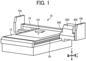
- FIG. 1 is a perspective view of an inkjet recording apparatus 10 as an image forming apparatus (liquid discharge apparatus) according to embodiments of the present disclosure.
- the inkjet recording apparatus 10 includes a carriage 200 and a stage 13 on which a recording medium 101 is placed.
- the carriage 200 is provided with a head device 350 (see FIG. 5 ) which is an inkjet image forming unit including multiple recording heads (liquid discharge heads) having multiple nozzles.
- the inkjet recording apparatus 10 discharges a liquid from the nozzles of the recording head (liquid discharge head) to forms an image. Nozzles of the recording head faces the stage 13.
- the liquid is, for example, ultraviolet (UV) curable ink.
- An irradiation device 400 which is a light source for emitting UV rays, is mounted on a side face of the carriage 200 so as to face the stage 13.
- the irradiation device 400 emits light (e.g., UV rays) having a specific wavelength to cure the ink (liquid) discharged from the nozzles of the recording head.
- a guide rod 19 is bridged between left and right side plates 18a and 18b.
- the guide rod 19 movably holds the carriage 200 in the X direction (main scanning direction).
- the carriage 200, the guide rod 19, and the side plates 18a and 18b are combined as a single body and movable together in the Y direction (sub-scanning direction) along a guide rail 29 disposed below the stage 13. Further, the guide rod 19 movably holds the carriage 200 in the Z direction (vertical direction).
- the stage 13 on which the recording medium 101 is placed may be stationary or may be moved relative to the carriage 200 in the direction indicated by arrow T illustrated in FIG 1 , for example.
- the inkjet recording apparatus 10 illustrated in FIG. 1 discharges the ink (liquid) from the nozzles onto the recording medium 101 while moving the recording head in the main scanning direction as a main scanning operation, and moves the recording head in the sub-scanning direction as a sub-scanning operation.
- the inkjet recording apparatus 10 alternately repeats the main scanning operation and the sub-scanning operation to form an image.
- the carriage 200, the guide rod 19, and the guide rail 29 function as an example of a printing device that performs a multi-pass printing process in which the main scanning operation and the sub-scanning operation are alternately repeated.
- the main scanning operation is an example of a main scanning movement operation in which the inkjet recording apparatus 10 moves the recording head relative to the recording medium 101 in the main scanning direction (X direction) orthogonal to the sub-scanning direction (Y direction) while causing the recording head to discharge the ink to the recording medium 101.
- the sub-scanning operation is an example of a sub-scanning movement operation in which the inkjet recording apparatus 10 moves one of the recording head and the recording medium 101 relative to another of the recording head and the recording medium 101 in the sub-scanning direction while causing the recording head not to discharge the ink.
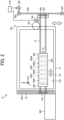
- FIG. 2 is a schematic plan view of the inkjet recording apparatus 10 as the image forming apparatus (liquid discharge apparatus) according to embodiments of the present disclosure.
- FIG. 3 is a schematic front view of the inkjet recording apparatus 10 according to embodiments of the present disclosure.
- an arrangement of some components is different from that in FIG. 1 for convenience of explanation, but these components have the same functions as in FIG. 1 .
- the recording heads 300K, 300C, 300M, 300Y, 300CL, and 300W mounted on the carriage 200 are moved in the sub-scanning direction relative to the recording medium 101 in the sub-scanning operation.
- the recording heads 300K, 300C, 300M, 300Y, 300CL, and 300W are also collectively referred to as “recording heads 300," and each of the recording heads 300K, 300C, 300M, 300Y, 300CL, and 300W is simply referred to as a "recording head 300" unless distinguished.
- the stage 13 on which the recording medium 101 is placed can be moved relative to the carriage 200 in the sub-scanning direction.
- the stage 13 serves as a conveyance device in the sub-scanning direction, and moves (conveys) the recording medium 101 in the sub-scanning direction relative to the recording heads 300 in the sub-scanning operation.
- the recording heads 300K, 300C, 300M, 300Y, 300CL, and 300W are arranged side by side in the main scanning direction in one row in a single head array on the carriage 200, but multiple recording heads 300K, 300C, 300M, 300Y, 300CL, and 300W may be arranged in multiple rows in the sub-scanning direction in the single head array.
- FIG. 4 is a plan view of recording heads 300a and 300b illustrating an example of an arrangement of nozzles 301a and 301b in the inkjet recording apparatus 10 according to embodiments of the present disclosure.
- the carriage 200 may include the recording head 300a for color ink, such as the recording heads 300K, 300C, 300M, and 300Y, and the recording head 300b for background ink, such as the recording heads 300CL and 300W, arranged as illustrated in FIG. 4 .
- the recording head 300a for color and the recording head 300b for background ink have multiple nozzles 301a and 301b from which the ink is discharged, respectively.
- the nozzles 301a and the nozzles 301b are arranged in the sub-scanning direction indicated by arrow SSD in FIG. 4 .
- the recording head 300a for color ink and the recording head 300b for background ink are arranged such that the positions of the nozzles 301a coincide with the positions of the nozzles 301b in the sub-scanning direction in an overlap region Ro having a length L.
- the recording head 300a for color ink and the recording head 300b for background ink overlap each other in the overlap region Ro. That is, the recording head 300a for color ink and the recording head 300b for background ink are arranged side by side in the main scanning direction indicated by arrow MSD, and the nozzles 301a of the recording head 300a for color ink and the nozzles 301b of the recording head 300b for background ink overlap each other in the overlapping region Ro in the sub scanning direction indicated by arrow SSD.
- the recording head 300a for color ink and the recording head 300b for background ink includes driving elements corresponding to the nozzles 301a and 301b, respectively, and drive pulses are applied to the driving elements to control droplets of the ink discharged from the recording head 300a for color ink and the recording head 300b for background ink.
- a piezoelectric element such as lead zirconate titanate (PZT) is used as the driving element.
- each of the recording heads 300a and the recording head 300b is simply referred to as a "recording head 300.”
- the nozzles 301a and the nozzles 301b are collectively referred to as “nozzles 301,” and each of the nozzles 301a and the nozzles 301b is also simply referred to as a “nozzle 301" unless distinguished.
- FIG. 5 is a block diagram of a hardware configuration of an image forming system according to embodiments of the present disclosure.
- a personal computer (PC) 2 as an external device is connected to the image forming apparatus (inkjet recording apparatus 10 illustrated in FIGS. 1 to 3 ) having a mechanical structure to form an image.
- the PC 2 performs image processing on the image to be formed.
- the image forming apparatus (inkjet recording apparatus 10) may have functions related to the image processing performed by the PC 2.
- the image forming apparatus (inkjet recording apparatus 10) according to the present embodiment includes a controller 3, detectors 414, a conveyance device 100, the carriage 200, the head device 350, the irradiation device 400, and a maintenance device 500.
- the controller 3 as circuitry includes a device control circuit 31, a memory 32, a central processing unit (CPU) 33, and an interface (I/F) 34.
- the I/F 34 connects the image forming apparatus (inkjet recording apparatus 10) to the PC 2 as an external device.
- the image forming apparatus (inkjet recording apparatus 10) and the PC 2 can be connected in any form, for example, via a network or directly connected by a communication cable.
- Examples of the detectors 414 include various sensors in the inkjet recording apparatus 10.
- the CPU 33 uses the memory 32 as a working area to control an operation of each device of the inkjet recording apparatus 10 via the device control circuit 31. Specifically, the CPU 33 controls the operation of each device such as the conveyance device 100, the carriage 200, the head device 350, the irradiation device 400, and the maintenance device 500 to form an image on the recording medium 101 based on recording data received from the PC 2 and data detected by the detectors 414.
- the image formed on the recording medium 101 is formed by the droplets of the ink (liquid) discharged from the head device 350.
- the droplets of the ink landed on the recording medium 101 form a liquid application surface 102 (i.e., the image) as illustrated in FIG. 3 .
- the recording medium 101 is also referred to as a "substrate.”
- the CPU 33 includes a color division data generation unit 511, a first quantization processing unit 512, and a second quantization processing unit 513.
- the operations of the color division data generation unit 511, the first quantization processing unit 512, and the second quantization processing unit 513 are described later.
- a printer driver is installed in the PC 2 to generate the recording data to be transmitted to the inkjet recording apparatus 10 from image data.
- the recording data includes command data to operate the conveyance device 100 and the like of the inkjet recording apparatus 10 and pixel data related to an image (liquid application surface 102) to be formed on the recording medium 101.
- the pixel data includes 2-bit data for each pixel, and is represented by 4 gradations, for example.
- the conveyance device 100 includes the stage 13 and a suction mechanism 120 as illustrated in FIG. 3 .
- the suction mechanism 120 includes fans 110 and a plurality of suction holes 100a formed in the stage 13.
- the suction mechanism 120 drives the fans 110 to suck the recording medium 101 through the plurality of suction holes 100a to temporarily secure the recording medium 101 on the stage 13 of the conveyance device 100.
- the suction mechanism 120 may attract the recording medium 101 onto the stage 130 using electrostatic attraction.
- the conveyance device 100 controls a relative movement between the carriage 200 and the recording medium 101 in the Y direction (sub-scanning direction) based on a drive signal from the CPU 33 via the device control circuit 31.
- the conveyance device 100 includes a conveyance controller 210, a roller 105, and a motor 104.
- the conveyance controller 210 drives the motor 104 to rotate the roller 105 to move the recording medium 101 on the stage 13 in the Y direction (sub-scanning direction).
- the conveyance device 100 moves the carriage 200 in the Y direction (sub-scanning direction) in addition to the recording medium 101. That is, the conveyance device 100 moves one of the recording medium 101 and the carriage 200 relative to another of the recording medium 101 and the carriage 200 in the Y direction (sub-scanning direction).
- the conveyance device 100 includes the side plate 18b that supports the guide rod 19 to guide the carriage 200 in the X direction (main-scanning direction), a base 406 that supports the side plate 18b, a belt 404 coupled to the base 406, a drive pulley 403 and a driven pulley 402 around which the belt 404 is looped, a motor 405 that rotationally drives the drive pulley 403, and the conveyance controller 210.
- the conveyance device 100 further includes the side plate 18a that supports the guide rod 19 to guide the carriage 200 in the X direction (main-scanning direction), a base 408 that slidably supports the side plate 18a, and the guide rail 29 formed in the base 408 to guide the side plate 18a in the sub-scanning direction.
- the conveyance device 100 controls the conveyance controller 210 to drive the motor 405 to rotate the drive pulley 403 and move the belt 404 in the Y direction (sub-scanning direction).
- the base 406 that supports the guide rod 19 holding the carriage 200 moves in the Y direction (sub-scanning direction) together with a movement of the belt 404. Accordingly, the carriage 200 moves in the Y direction (sub-scanning direction).
- the side plate 18a moves in the Y direction (sub-scanning direction) along the guide rail 29 in the base 408 as the base 406 moves in the Y direction (sub-scanning direction).
- the head device 350 includes the recording heads 300K, 300C, 300M, 300Y, 300CL, and 300W that discharge UV curable inks of black (K), cyan (C), magenta (M), yellow (Y), clear (CL), and white (W), respectively.
- the head device 350 is disposed on a lower face of the carriage 200.
- the recording heads 300K, 300C, 300M, 300Y, 300CL, and 300W may be formed in the single head array, or each of the recording heads 300K, 300C, 300M, 300Y, 300CL, and 300W may be formed in the single head array.
- the single head array includes the multiple recording heads 300
- the multiple recording heads 300 may be arranged in a staggered manner or in one row.
- the recording head 300 includes the piezoelectric element as the driving element.
- the CPU 33 the device control circuit 31
- the piezoelectric element contracts and expands to change a pressure of the ink (liquid) in the recording head 300, thereby discharge the UV curable ink onto the recording medium 101.
- the droplets of the ink discharged from the recording head 300 form the liquid application surface 102 on the recording medium 101.
- the UV curable ink suitable in the present embodiment includes, for example, ink containing a methacrylate monomer.
- Methacrylate monomer has an advantage of relatively weak skin sensitization but has characteristics of large cure shrinkage as compared with a normal ink.
- the irradiation device 400 is disposed on the side face (surface in the X direction) of the carriage 200.
- the irradiation device 400 irradiates the liquid application surface 102 on the recording medium 101 with UV rays based on a drive signal from the CPU 33 (device control circuit 31).
- the irradiation device 400 includes a UV irradiation lamp that emits UV rays.
- the carriage 200 moves in the Z direction (height direction) and the X direction (main-scanning direction) based on a drive signal from the CPU 33 (device control circuit 31).
- the carriage 200 moves along the guide rod 19 in the main-scanning direction (X direction).
- a scanning device 206 includes a drive pulley 203, a driven pulley 204, a drive belt 202, and a motor 205.
- the carriage 200 is secured to the drive belt 202 looped around the drive pulley 203 and the driven pulley 204.
- the motor 205 rotates the drive pulley 203 to move the drive belt 202, the carriage 200 moves left and right in FIG. 3 in the main-scanning direction (X direction).
- the guide rod 19 is supported by the side plates 18a and 18b.
- a height adjuster 207 includes a motor 209 and a slider 208.
- the height adjuster 207 drives the motor 209 to vertically move the slider 208, thereby moving the guide rod 19 upward and downward.
- the carriage 200 moves up and down to adjust the height of the carriage 200 with respect to the recording medium 101.
- the conveyance device 100 moves the recording medium 101 in the Y direction (sub-scanning direction) based on a drive signal from the CPU 33 (device control circuit 31) so that the recording medium 101 is positioned at an initial position to form an image (liquid application surface 102) on the recording medium 101.
- the carriage 200 moves to a height suitable for the head device 350 to discharge the UV curable ink (liquid) based on a drive signal from the CPU 33 (the device control circuit 31), for example, a height at which a gap between the lower surface of each recording head 300 of the head device 350 and the recording medium 101 is 1 mm.
- a height sensor 41 detects a height of the head device 350, and the CPU 33 acquires data of the height from the height sensor 41.
- the carriage 200 reciprocally moves in the X direction (main-scanning direction) based on a drive signal from the CPU 33 (device control circuit 31).
- the head device 350 discharges the UV curable ink (liquid) onto the recording medium 101 based on a drive signal from the CPU 33 (device control circuit 31).
- an image (liquid application surface 102) for one scan is formed on the recording medium 101.
- the conveyance device 100 moves the carriage 200 by a distance corresponding to the length of the image formed in the one scan in the Y direction (sub-scanning direction) based on a drive signal from the CPU 33 (device control circuit 31).
- An operation of forming an image (liquid application surface 102) for one scan i.e., the main scanning operation
- an operation of moving the carriage 200 in the Y direction (sub-scanning direction) by the distance for one scan i.e., the sub-scanning operation
- the inkjet recording apparatus 10 waits for a predetermined time until the UV curable ink on the recording medium 101 is leveled (flattened). Above-described waiting time is also referred to as "leveling time.” Then, the irradiation device 400 irradiates the liquid application surface 102 on the recording medium 101 with UV rays.
- FIG. 6 is a flowchart of the multi-pass printing process in the inkjet recording apparatus 10 according to embodiments of the present disclosure. A description is given below of the example of the multi-pass printing process in the inkjet recording apparatus 10 according to the present embodiment with reference to FIGS. 5 and 6 .
- the color division data generation unit 511 When the controller 3 receives image data to be printed (step S800), the color division data generation unit 511 generates color division data for each color of ink used in the inkjet recording apparatus 10 from the received image data (an example of input data or an input image input to the controller 3) (step S801). For example, when the inkjet recording apparatus 10 uses inks of C, M, Y, and K, the color division data generation unit 511 generates color division data for each color of C, M, Y, and K from the received image data.
- the first quantization processing unit 512 applies the dot-data generation mask to the color division data of each color generated by the color division data generation unit 511 to generate dot-data (step S802).
- the dot data generation mask is, for example, a dither mask having a threshold value used in halftone processing. That is, the first quantization processing unit 512 converts the image data into the dot data. At this time, the CPU 33 converts the image date into the dot date including at least two types of dots.
- the dot data includes, as at least two types of dots, a dot (i.e., a first dot) formed by a small droplet and a dot (i.e., a second dot) formed by a large droplet having a larger droplet volume than the dot of the small droplet.
- the dot data may include a dot of a medium droplet having a larger droplet volume than the dot of the small droplet and a smaller droplet volume than the dot of the large droplet.
- the second quantization processing unit 513 applies a selective-discharge mask to the dot data generated by the first quantization processing unit 512 to generate scan data (step S803). That is, the second quantization processing unit 513 determines to use which of the nozzles 301a and 301b to form a dot of the image for each scan of the recording heads 300 in the main scanning direction.
- the selective-discharge mask is an example of a mask having two or more bits.
- the second quantization processing unit 513 converts the dot data into the scan data for each scan (i.e., the main scanning movement operation) using the dot data and the selective-discharge mask by calculation.
- the second quantization processing unit 514 changes a selective-discharge method of dots (e.g., changes the selective-discharge mask) in accordance with the types of dots in the dot data.
- the selective-discharge method of the dots can be continuously changed without switching the selective-discharge method at a specific gradation. As a result, deterioration of image quality can be prevented, in particular, in an image with gradient.
- the device control circuit 31 outputs (transfers) the generated scan data to a drive circuit in the recording head 300 (step S804) to cause the recording head 300 to discharge the liquid according to the scan data, thereby printing an image on the recording medium 101 based on the scan data.
- FIG. 7 is a diagram illustrating an example of scan data generation processing executed by the inkjet recording apparatus 10 according to a first embodiment of the present disclosure. A description is given below of the scan data generation processing executed by the inkjet recording apparatus 10 according to the present embodiment with reference to FIG. 7 .
- the scan data generation processing for first and third scans of the recording head 300 in a multi-scanning with 2-pass 1/2-interlace is described below, and the scan data generation processing for second and fourth scans is executed in the same manner.
- the second quantization processing unit 513 extracts pixels (dot data at first and third scan nozzle positions) on scanning lines of the nozzles 301 in the first and third scans of the recording head 300.
- the broken lines in FIG. 7 indicate the scanning lines along which the nozzles 301 are moved in the first and third scans, and the second quantization processing unit 513 extracts the pixels (the dot data at the first and third scan nozzle positions) on the scanning lines.
- the second quantization processing unit 513 generates scan data (first and third scan data) for each of the first scan and the third scan by performing mask processing on the extracted pixels using the selective-discharge mask (i.e., the selective-discharge mask for the first scan and the selective-discharge mask for the third scan). For example, as illustrated in FIG. 7 , the second quantization processing unit 513 applies the selective-discharge mask for the first scan to the dot data for the first and third scans to generate scan data for the first scan, and applies the selective-discharge mask for the third scan to the dot data for the first and third scans to generate scan data for the third scan.
- the selective-discharge mask for the first scan to the dot data for the first and third scans to generate scan data for the first scan
- the selective-discharge mask for the third scan to the dot data for the first and third scans to generate scan data for the third scan.
- the second quantization processing unit 513 generates the scan data indicating that ink (liquid) is discharged to a pixel corresponding to a digit "1" of the selective-discharge mask illustrated in FIG. 7 and indicating that ink is not discharged to a pixel corresponding to a digit "0" of the selective-discharge mask illustrated in FIG. 7 among the pixels of the dot data.
- the selective-discharge mask is provided for each scan of the recording head 300 to indicate a dot arrangement position which is positions of the pixels to which ink is discharged from the nozzles 301 in the scan.
- the selective-discharge mask includes binary data indicating whether or not ink (liquid) is discharged from the nozzles 301 for each dot.
- the selective-discharge masks (e.g., for the first scan and for the third scan) complement each other to generate the scan date in which the positions of the nozzles 301 in the sub-scanning direction overlap each other.
- the second quantization processing unit 513 performs the mask processing on the dot data with multiple selective-discharge masks that complement each other to decompose the dot data into multiple sets of scan data corresponding to the number of scans of the recording head 300.
- FIG. 8 is a diagram illustrating the selective-discharge method of the dots for each gradation by the inkjet recording apparatus 10 according to the first embodiment.
- a light-colored region has a smaller discharge amount of ink than a dark-colored region.
- the discharge amount corresponds to the ratio of dots discharged on the recording medium 101 in each scan to the dots in the original dot data.
- a dot diameter at an end of the recording head 300 (hereinafter, referred to as a head end region) is different from dot diameters at the other region. Accordingly, a mask A is desirable to reduce the discharge amount of ink to be discharged from the head end region of the recording head 300 to the recording medium 101.
- the image density is saturated, and the image density unevenness is likely to be inconspicuous.
- a surface state of the image (liquid application surface 102) is likely to be uneven, and a gloss unevenness becomes noticeable, in particular, when the UV ink is used.
- the mask A having a sharp change in the discharge amount of ink the surface state of the image changes in a region where the discharge amount changes, and thus the gloss unevenness may occur. Accordingly, a mask B having a small change in the discharge amount of ink is desirable in the high gradation region.
- the second quantization processing unit 513 changes the selective-discharge method in accordance with the gradation, thereby enhancing the image quality.
- FIG. 9 is a graph illustrating the effect obtained by changing the selective-discharge method for each droplet type in the inkjet recording apparatus 10 according to the first embodiment.
- the horizontal axis represents an input (gradation of the input image, which is also referred to as an input gradation), and the vertical axis represents an output (the discharge amount of each droplet type).
- the second quantization processing unit 513 changes the selective-discharge method (e.g., changes the selective-discharge mask) for each droplet type. Normally, the droplet types used for printing are controlled and replaced as illustrated in FIG. 9 . For example, when the input gradation, which is the gradation of the input image, is 50%, the second quantization processing unit 513 converts the dot data including 50% of large droplets and 50% of small droplets into the scan data. As illustrated in FIG.
- the first quantization processing unit 512 converts the input image into the dot data so as to increase the ratio of dots of the small droplet to all dots and decrease the ratio of dots of the large droplet to all dots in the low gradation region as compared with in the high gradation region.
- the second quantization processing unit 513 applies the mask A to the dots of the small droplet in the dot data to convert the dot data into the scan data.
- the discharge amount at the end of the recording head 300 is lower than that at the center of the recording head 300 in the mask A.
- the second quantization processing unit 513 applies the mask B to the dots of the large droplet in the dot data to convert the dot data into the scan data.
- a change rate in the discharge amount in the mask B is smaller than that in the mask A for the small droplet.
- the discharge amount by the mask B continuously increases with an increase in the input gradation.
- the second quantization processing unit 513 uses the mask A in 50% of the dot data and the mask B in the 50% of the dot data.
- the second quantization processing unit 513 changes the selective-discharge method (e.g., the selective-discharge mask) for each droplet type, and continuously changes the selective-discharge method in accordance with the image density. Accordingly, the deterioration of the image quality can be prevented, in particular, in an image with gradient.
- FIG. 10 and FIG. 11 are charts illustrating processing of changing the selective-discharge method by the inkjet recording apparatus 10 according to the first embodiment.
- dot data which is an example of raster image processor (RIP) data
- digits "00” represents a blank
- digits "01” represents the small droplet
- digits "10” represents the medium droplet
- digits "11” represents the large droplet in the image.
- the second quantization processing unit 513 converts the dot data into the scan data for each scan using the selective-discharge mask prepared in advance and a calculation table as a second quantization processing.
- the calculation table is a table in which the dot data is associated with the selective-discharge mask applied to the dot data.
- the calculation table is stored in the memory 32 of the controller 3.
- the selective-discharge mask illustrated in FIG. 10 has three types of dots and three bits.
- the selective-discharge mask has 1 column horizontally, 8 rows vertically, and 3 bits, for example.
- the dot date (RIP data) has 8 columns horizontally, 8 rows vertically, and 2 bits, for example.
- the second quantization processing unit 513 may perform the calculation between the selective-discharge mask and the dot data (RIP data) using the calculation table to generate the scan data (see FIG. 11 ).
- the inkjet recording apparatus 10 continuously changes the selective-discharge method in accordance with the image density.
- the inkjet recording apparatus 10 does not switch the selective-discharge method stepwise at a specific gradation.
- the deterioration of the image quality can be prevented, in particular, in an image with gradient.
- a second embodiment is described below.
- a place (i.e., the number of digit) of the bits of the selective-discharge mask with which the dot data is calculated is different depending on the type of dot in the dot data. Redundant descriptions of the same components as those described above in the first embodiment may be omitted below.
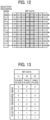
- FIGS. 12 to 14 are charts illustrating processing of changing the selective-discharge method by the inkjet recording apparatus 10 according to the second embodiment.
- the second quantization processing unit 513 may change the place (the number of digit) of the bits of the selective-discharge mask to be calculated in accordance with the types of dot data (droplet type).
- the number of bits of the selective-discharge mask is equal to or greater than the number of types of dot data.
- the second quantization processing unit 513 may change the selective-discharge method for all droplet types of dots in the dot data.
- the second quantization processing unit 513 determines whether or not to discharge ink (i.e., 0: non-discharge or 1: discharge) by fours place (a third digit) of the bits for the large droplet, twos place (a second digit) of the bits for the medium droplet, and ones place (i.e., a first digit) for the small droplet.
- the second quantization processing unit 513 generates the scan data as illustrated in FIG. 14 .
- the inkjet recording apparatus 10 according to the second embodiment achieves the same effects as those in the first embodiment.
- a third embodiment is described below.
- the number of the bits of the selective-discharge mask is smaller than the number of types of dots in the dot data. Redundant descriptions of the same components as those described above in the first embodiment may be omitted below.
- FIG. 15 and FIG. 16 are charts illustrating processing of changing the selective-discharge method by the inkjet recording apparatus 10 according to the third embodiment.
- the number of bits of the selective-discharge mask is smaller than the number of types of dots. For this reason, the number of droplet types for changing the selective-discharge method can be reduced, thereby increasing the processing speed of the conversion processing from the dot data to the scan data.
- the second quantization processing unit 513 performs the calculation between the selective-discharge mask and the dot data (RIP data) using the calculation table.
- the second quantization processing unit 513 generates the scan data as illustrated in FIG. 16 .
- the number of droplet types for changing the selective-discharge method can be reduced, thereby increasing the processing speed of the conversion processing from the dot data to the scan data.
- the selective-discharge mask causes the recording head 300 to reduce the discharge amount of ink at the end of the recording head 300 lower than that at the center of the recording head 300 for the dots in the low gradation region among the dots in the dot data, and causes the recording head 300 to reduce the change rate in the discharge amount of ink for the dots in the high gradation region among the dots in the dot data lower than that in the low gradation region. Redundant descriptions of the same components as those in the above-described embodiments may be omitted below.
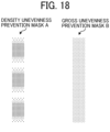
- FIG. 17 and FIG. 18 are diagrams illustrating processing of changing the selective-discharge method by the inkjet recording apparatus 10 according to the fourth embodiment.
- the selective-discharge mask causes the recording head 300 to reduce the discharge amount of ink at the end of the recording head 300 lower than that at the center of the recording head 300 for the dots in the low gradation region among the dots in the dot data.
- the selective-discharge mask causes the recording head 300 to discharge the liquid for a first discharge amount at each of end portions of the recording head 300 and discharge the liquid for a second discharge amount larger than the first discharge amount at a center portion between the end portions of the recording head 300. Accordingly, in the low gradation region, the selective-discharge mask reduces the discharge amount of ink to be discharged from the head end region of the recording head 300, thereby preventing the image density unevenness.
- the selective-discharge mask causes the recording head 300 to reduce the change rate in the discharge amount of ink for the dots in the high gradation region lower than that in the low gradation region among the dots in the dot data.
- the selective-discharge mask causes the recording head 300 to discharge the liquid with a first change rate between the first discharge amount and the second discharge amount for the two or more types of dots in the first gradation region and the selective-discharge mask causes the recording head 300 to discharge the liquid with a second change rate between the first discharge amount and the second discharge amount for the two or more types of dots in the second gradation region.
- the second change rate is smaller than the first change rate.
- the selective-discharge mask reduces the change rate in the discharge amount of ink, thereby preventing the gloss unevenness.
- the second quantization processing unit 513 uses a density unevenness prevention mask A for the small droplets and a gloss unevenness prevention mask B for the large droplets as illustrated in FIG. 18 .
- the inkjet recording apparatus 10 changes the selective-discharge method depending on the gradation so as to reduce the discharge amount at the end of the recording head 300 in the low gradation region to prevent the image density unevenness, and so as to reduce the sharp change in the discharge amount in the high gradation region to prevent the gloss unevenness.
- Programs executed in the inkjet recording apparatus 10 according to the present embodiment is installed in the memory 32 such as a read only memory (ROM) in advance.
- the programs executed in the inkjet recording apparatus 10 according to the present embodiment may be stored, in an installable or executable file format, in a computer readable recording medium, such as a compact disc read only memory (CD-ROM), a flexible disk (FD), a compact disc recordable (CD-R), and a digital versatile disk (DVD).
- CD-ROM compact disc read only memory
- FD flexible disk
- CD-R compact disc recordable
- DVD digital versatile disk
- the programs executed in the inkjet recording apparatus 10 according to the present embodiment may be stored in a computer connected to a network such as the Internet and downloaded via the network.
- the computer programs executed in the inkjet recording apparatus 10 according to the present embodiment may be supplied or distributed via a network such as the Internet.
- the program executed by the inkjet recording apparatus 10 has a modular configuration including the above-described units (the color division data generation unit 511, the first quantization processing unit 512, and the second quantization processing unit 513).
- the CPU 33 (an example of a processor) serving as actual hardware reads the programs from the memory 32 such as the ROM and executes the programs so as to load these units on a main storage device to implement the color division data generation unit 511, the first quantization processing unit 512, and the second quantization processing unit 513 on the main storage device.
- the present invention can be implemented in any convenient form, for example using dedicated hardware, or a mixture of dedicated hardware and software.
- the present invention may be implemented as computer software implemented by one or more networked processing apparatuses.
- the processing apparatuses include any suitably programmed apparatuses such as a general purpose computer, a personal digital assistant, a Wireless Application Protocol (WAP) or third-generation (3G)-compliant mobile telephone, and so on. Since the present invention can be implemented as software, each and every aspect of the present invention thus encompasses computer software implementable on a programmable device.
- the computer software can be provided to the programmable device using any conventional carrier medium (carrier means).
- the carrier medium includes a transient carrier medium such as an electrical, optical, microwave, acoustic or radio frequency signal carrying the computer code.
- transient medium is a Transmission Control Protocol/Internet Protocol (TCP/IP) signal carrying computer code over an IP network, such as the Internet.
- the carrier medium may also include a storage medium for storing processor readable code such as a floppy disk, a hard disk, a compact disc read-only memory (CD-ROM), a magnetic tape device, or a solid state memory device.
Landscapes
- Engineering & Computer Science (AREA)
- Physics & Mathematics (AREA)
- Mathematical Physics (AREA)
- General Engineering & Computer Science (AREA)
- General Physics & Mathematics (AREA)
- Theoretical Computer Science (AREA)
- Quality & Reliability (AREA)
- Ink Jet (AREA)
- Particle Formation And Scattering Control In Inkjet Printers (AREA)
- Facsimile Image Signal Circuits (AREA)
Abstract
Description
- Embodiments of the present disclosure relate to a liquid discharge apparatus, a liquid discharge method, and a carrier medium carrying computer readable code.
- In the related art, a serial inkjet printer performs mask processing in which dot data after halftone processing is scanned with a mask pattern to print an image. In the mask processing, a technique has been developed in which several thresholds are provided for image density levels of the dot data after the halftone processing, and the mask pattern is switched in accordance with the thresholds, thereby changing a selective-discharge method for each gradation (see
Japanese Unexamined Patent Application Publication No. 2004-209943 - The present disclosure has been made in view of the above circumstances, and an object of the present disclosure is to provide a liquid discharge apparatus, a liquid discharge method, and a storage medium storing a plurality of instructions to enhance an image quality.
- Embodiments of the present disclosure describe an improved liquid discharge apparatus that includes a recording head and circuitry comprising a selective-discharge mask having two or more bits. The circuitry moves the recording head relative to a recording medium in a main scanning direction while causing the recording head to discharge a liquid onto the recording medium to perform a main scanning movement operation, moves one of the recording head and the recording medium relative to another of the recording head and the recording medium in a sub-scanning direction orthogonal to the main scanning direction while causing the recording head not to discharge the liquid to perform a sub-scanning movement operation, alternately repeats the main scanning movement operation and the sub-scanning movement operation to perform a multi-pass printing process, converts input data to dot data including two or more types of dots, changes the selective-discharge mask in accordance with types of the two types of dots, converts the dot data to scan data for each of the main scanning movement operation of the multi-pass printing process using the dot data and the selective-discharge mask, and transfers the scan data to the recording head to cause the recording head to discharge the liquid according to the scan data.
- According to other embodiments of the present disclosure, there are provided a liquid discharge method and a carrier medium carrying computer readable code for controlling a computer system to carry out the liquid discharge method. The method includes moving a recording head relative to a recording medium in a main scanning direction while causing the recording head to discharge a liquid onto the recording medium to perform a main scanning movement operation, moving one of the recording head and the recording medium relative to another of the recording head and the recording medium in a sub-scanning direction orthogonal to the main scanning direction while causing the recording head not to discharge the liquid to perform a sub-scanning movement operation, alternately repeating the main scanning movement operation and the sub-scanning movement operation to perform a multi-pass printing process, converting input data to dot data including two or more types of dots, changing the selective-discharge mask in accordance with types of the two or more types of dots, converting the dot data to scan data for each of the main scanning movement operation of the multi-pass printing process using the dot data and the selective-discharge mask, and transferring the scan data to the recording head to cause the recording head to discharge the liquid according to the scan data.
- As a result, according to the present disclosure, the image quality can be enhanced.
- A more complete appreciation of the disclosure and many of the attendant advantages and features thereof can be readily obtained and understood from the following detailed description with reference to the accompanying drawings, wherein:
-
FIG. 1 is a perspective view of an inkjet recording apparatus as an image forming apparatus (liquid discharge apparatus) according to embodiments of the present disclosure; -
FIG. 2 is a schematic plan view of the inkjet recording apparatus according to embodiments of the present disclosure; -
FIG. 3 is a schematic front view of the inkjet recording apparatus according to embodiments of the present disclosure; -
FIG. 4 is a plan view of an arrangement of nozzles in a recording head of the inkjet recording apparatus according to embodiments of the present disclosure; -
FIG. 5 is a block diagram of a hardware configuration of an image forming system including the inkjet recording apparatus according to embodiments of the present disclosure; -
FIG. 6 is a flowchart illustrating a multi-pass printing process in the inkjet recording apparatus according to embodiments of the present disclosure; -
FIG. 7 is a diagram illustrating scan data generation processing executed by the inkjet recording apparatus according to a first embodiment of the present disclosure; -
FIG. 8 is a diagram illustrating a selective-discharge method of dots for each gradation performed by the inkjet recording apparatus according to the first embodiment; -
FIG. 9 is a graph illustrating an effect obtained by changing the selective-discharge method for each droplet type by the inkjet recording apparatus according to the first embodiment; -
FIG. 10 is a chart illustrating processing of changing the selective-discharge method by the inkjet recording apparatus according to the first embodiment; -
FIG. 11 is a chart illustrating the processing of changing the selective-discharge method by the inkjet recording apparatus according to the first embodiment; -
FIG. 12 is a chart illustrating processing of changing the selective-discharge method by the inkjet recording apparatus according to a second embodiment; -
FIG. 13 is a chart illustrating the processing of changing the selective-discharge method by the inkjet recording apparatus according to the second embodiment; -
FIG. 14 is a chart illustrating the processing of changing the selective-discharge method by the inkjet recording apparatus according to the second embodiment; -
FIG. 15 is a chart illustrating processing of changing the selective-discharge method by the inkjet recording apparatus according to a third embodiment; -
FIG. 16 is a chart illustrating the processing of changing the selective-discharge method by the inkjet recording apparatus according to the third embodiment; -
FIG. 17 is a graph illustrating processing of changing the selective-discharge method by the inkjet recording apparatus according to a fourth embodiment; and -
FIG. 18 is a diagram illustrating the processing of changing the selective-discharge method by the inkjet recording apparatus according to the fourth embodiment. - The accompanying drawings are intended to depict embodiments of the present invention and should not be interpreted to limit the scope thereof. The accompanying drawings are not to be considered as drawn to scale unless explicitly noted. Also, identical or similar reference numerals designate identical or similar components throughout the several views.
- In describing embodiments illustrated in the drawings, specific terminology is employed for the sake of clarity. However, the disclosure of this specification is not intended to be limited to the specific terminology so selected and it is to be understood that each specific element includes all technical equivalents that have a similar function, operate in a similar manner, and achieve a similar result.
- Referring now to the drawings, embodiments of the present disclosure are described below. As used herein, the singular forms "a," "an," and "the" are intended to include the plural forms as well, unless the context clearly indicates otherwise.
- Embodiments of a liquid discharge apparatus, a liquid discharge method, and a storage medium is described in detail below with reference to the accompanying drawings.
- A description is given of embodiments of the present disclosure.
FIG. 1 is a perspective view of aninkjet recording apparatus 10 as an image forming apparatus (liquid discharge apparatus) according to embodiments of the present disclosure. - The
inkjet recording apparatus 10 includes acarriage 200 and astage 13 on which arecording medium 101 is placed. Thecarriage 200 is provided with a head device 350 (seeFIG. 5 ) which is an inkjet image forming unit including multiple recording heads (liquid discharge heads) having multiple nozzles. Theinkjet recording apparatus 10 discharges a liquid from the nozzles of the recording head (liquid discharge head) to forms an image. Nozzles of the recording head faces thestage 13. In the present embodiment, the liquid is, for example, ultraviolet (UV) curable ink. - An
irradiation device 400, which is a light source for emitting UV rays, is mounted on a side face of thecarriage 200 so as to face thestage 13. Theirradiation device 400 emits light (e.g., UV rays) having a specific wavelength to cure the ink (liquid) discharged from the nozzles of the recording head. - A
guide rod 19 is bridged between left andright side plates guide rod 19 movably holds thecarriage 200 in the X direction (main scanning direction). Thecarriage 200, theguide rod 19, and theside plates guide rail 29 disposed below thestage 13. Further, theguide rod 19 movably holds thecarriage 200 in the Z direction (vertical direction). - In the configuration illustrated in
FIG. 1 , thestage 13 on which therecording medium 101 is placed may be stationary or may be moved relative to thecarriage 200 in the direction indicated by arrow T illustrated inFIG 1 , for example. Theinkjet recording apparatus 10 illustrated inFIG. 1 discharges the ink (liquid) from the nozzles onto therecording medium 101 while moving the recording head in the main scanning direction as a main scanning operation, and moves the recording head in the sub-scanning direction as a sub-scanning operation. Theinkjet recording apparatus 10 alternately repeats the main scanning operation and the sub-scanning operation to form an image. In other words, in theinkjet recording apparatus 10 according to the present embodiment, thecarriage 200, theguide rod 19, and theguide rail 29 function as an example of a printing device that performs a multi-pass printing process in which the main scanning operation and the sub-scanning operation are alternately repeated. - The main scanning operation is an example of a main scanning movement operation in which the
inkjet recording apparatus 10 moves the recording head relative to therecording medium 101 in the main scanning direction (X direction) orthogonal to the sub-scanning direction (Y direction) while causing the recording head to discharge the ink to therecording medium 101. The sub-scanning operation is an example of a sub-scanning movement operation in which theinkjet recording apparatus 10 moves one of the recording head and therecording medium 101 relative to another of the recording head and therecording medium 101 in the sub-scanning direction while causing the recording head not to discharge the ink. -
FIG. 2 is a schematic plan view of theinkjet recording apparatus 10 as the image forming apparatus (liquid discharge apparatus) according to embodiments of the present disclosure.FIG. 3 is a schematic front view of theinkjet recording apparatus 10 according to embodiments of the present disclosure. In theinkjet recording apparatus 10 illustrated inFIGS. 2 and3 , an arrangement of some components is different from that inFIG. 1 for convenience of explanation, but these components have the same functions as inFIG. 1 . - In
FIGS. 1 to 3 , therecording heads carriage 200 are moved in the sub-scanning direction relative to therecording medium 101 in the sub-scanning operation. Hereinafter, the recording heads 300K, 300C, 300M, 300Y, 300CL, and 300W are also collectively referred to as "recording heads 300," and each of the recording heads 300K, 300C, 300M, 300Y, 300CL, and 300W is simply referred to as a "recording head 300" unless distinguished. - In addition, the
stage 13 on which therecording medium 101 is placed can be moved relative to thecarriage 200 in the sub-scanning direction. In this case, thestage 13 serves as a conveyance device in the sub-scanning direction, and moves (conveys) therecording medium 101 in the sub-scanning direction relative to the recording heads 300 in the sub-scanning operation. - In
FIG. 2 , the recording heads 300K, 300C, 300M, 300Y, 300CL, and 300W are arranged side by side in the main scanning direction in one row in a single head array on thecarriage 200, but multiple recording heads 300K, 300C, 300M, 300Y, 300CL, and 300W may be arranged in multiple rows in the sub-scanning direction in the single head array. -
FIG. 4 is a plan view ofrecording heads nozzles inkjet recording apparatus 10 according to embodiments of the present disclosure. - The
carriage 200 may include therecording head 300a for color ink, such as the recording heads 300K, 300C, 300M, and 300Y, and therecording head 300b for background ink, such as the recording heads 300CL and 300W, arranged as illustrated inFIG. 4 . Therecording head 300a for color and therecording head 300b for background ink havemultiple nozzles recording head 300a for color ink and therecording head 300b for background ink, thenozzles 301a and thenozzles 301b are arranged in the sub-scanning direction indicated by arrow SSD inFIG. 4 . - The
recording head 300a for color ink and therecording head 300b for background ink are arranged such that the positions of thenozzles 301a coincide with the positions of thenozzles 301b in the sub-scanning direction in an overlap region Ro having a length L. Therecording head 300a for color ink and therecording head 300b for background ink overlap each other in the overlap region Ro. That is, therecording head 300a for color ink and therecording head 300b for background ink are arranged side by side in the main scanning direction indicated by arrow MSD, and thenozzles 301a of therecording head 300a for color ink and thenozzles 301b of therecording head 300b for background ink overlap each other in the overlapping region Ro in the sub scanning direction indicated by arrow SSD. - The
recording head 300a for color ink and therecording head 300b for background ink includes driving elements corresponding to thenozzles recording head 300a for color ink and therecording head 300b for background ink. For example, a piezoelectric element such as lead zirconate titanate (PZT) is used as the driving element. Hereinafter, each of the recording heads 300a and therecording head 300b is simply referred to as a "recording head 300." In addition, thenozzles 301a and thenozzles 301b are collectively referred to as "nozzles 301," and each of thenozzles 301a and thenozzles 301b is also simply referred to as a "nozzle 301" unless distinguished. - A description is given below of an example of a hardware configuration of an image forming system including the image forming apparatus (inkjet recording apparatus 10) with reference to
FIGS. 1 to 3 and5 . -
FIG. 5 is a block diagram of a hardware configuration of an image forming system according to embodiments of the present disclosure. In the image forming system illustrated inFIG. 5 , a personal computer (PC) 2 as an external device is connected to the image forming apparatus (inkjet recording apparatus 10 illustrated inFIGS. 1 to 3 ) having a mechanical structure to form an image. ThePC 2 performs image processing on the image to be formed. The image forming apparatus (inkjet recording apparatus 10) may have functions related to the image processing performed by thePC 2. - As illustrated in
FIG. 5 , the image forming apparatus (inkjet recording apparatus 10) according to the present embodiment includes acontroller 3,detectors 414, aconveyance device 100, thecarriage 200, thehead device 350, theirradiation device 400, and amaintenance device 500. Thecontroller 3 as circuitry includes adevice control circuit 31, a memory 32, a central processing unit (CPU) 33, and an interface (I/F) 34. - The I/F 34 connects the image forming apparatus (inkjet recording apparatus 10) to the
PC 2 as an external device. The image forming apparatus (inkjet recording apparatus 10) and thePC 2 can be connected in any form, for example, via a network or directly connected by a communication cable. Examples of thedetectors 414 include various sensors in theinkjet recording apparatus 10. - The CPU 33 uses the memory 32 as a working area to control an operation of each device of the
inkjet recording apparatus 10 via thedevice control circuit 31. Specifically, the CPU 33 controls the operation of each device such as theconveyance device 100, thecarriage 200, thehead device 350, theirradiation device 400, and themaintenance device 500 to form an image on therecording medium 101 based on recording data received from thePC 2 and data detected by thedetectors 414. The image formed on therecording medium 101 is formed by the droplets of the ink (liquid) discharged from thehead device 350. The droplets of the ink landed on therecording medium 101 form a liquid application surface 102 (i.e., the image) as illustrated inFIG. 3 . Therecording medium 101 is also referred to as a "substrate." - In the present embodiment, the CPU 33 includes a color division
data generation unit 511, a firstquantization processing unit 512, and a second quantization processing unit 513. The operations of the color divisiondata generation unit 511, the firstquantization processing unit 512, and the second quantization processing unit 513 are described later. - A printer driver is installed in the
PC 2 to generate the recording data to be transmitted to theinkjet recording apparatus 10 from image data. The recording data includes command data to operate theconveyance device 100 and the like of theinkjet recording apparatus 10 and pixel data related to an image (liquid application surface 102) to be formed on therecording medium 101. The pixel data includes 2-bit data for each pixel, and is represented by 4 gradations, for example. - Components in the mechanical structure of the image forming apparatus (inkjet recording apparatus 10) are described with reference to
FIGS. 2 ,3 , and5 . Theconveyance device 100 includes thestage 13 and asuction mechanism 120 as illustrated inFIG. 3 . Thesuction mechanism 120 includesfans 110 and a plurality ofsuction holes 100a formed in thestage 13. Thesuction mechanism 120 drives thefans 110 to suck therecording medium 101 through the plurality ofsuction holes 100a to temporarily secure therecording medium 101 on thestage 13 of theconveyance device 100. Thesuction mechanism 120 may attract therecording medium 101 onto the stage 130 using electrostatic attraction. Theconveyance device 100 controls a relative movement between thecarriage 200 and therecording medium 101 in the Y direction (sub-scanning direction) based on a drive signal from the CPU 33 via thedevice control circuit 31. - As illustrated in
FIG. 2 , theconveyance device 100 includes aconveyance controller 210, aroller 105, and amotor 104. Theconveyance controller 210 drives themotor 104 to rotate theroller 105 to move therecording medium 101 on thestage 13 in the Y direction (sub-scanning direction). - The
conveyance device 100 moves thecarriage 200 in the Y direction (sub-scanning direction) in addition to therecording medium 101. That is, theconveyance device 100 moves one of therecording medium 101 and thecarriage 200 relative to another of therecording medium 101 and thecarriage 200 in the Y direction (sub-scanning direction). - As illustrated on the right side of
FIG. 2 , theconveyance device 100 includes theside plate 18b that supports theguide rod 19 to guide thecarriage 200 in the X direction (main-scanning direction), a base 406 that supports theside plate 18b, abelt 404 coupled to thebase 406, adrive pulley 403 and a drivenpulley 402 around which thebelt 404 is looped, a motor 405 that rotationally drives thedrive pulley 403, and theconveyance controller 210. - As illustrated on the left side of
FIG. 2 , theconveyance device 100 further includes theside plate 18a that supports theguide rod 19 to guide thecarriage 200 in the X direction (main-scanning direction), a base 408 that slidably supports theside plate 18a, and theguide rail 29 formed in the base 408 to guide theside plate 18a in the sub-scanning direction. - The
conveyance device 100 controls theconveyance controller 210 to drive the motor 405 to rotate thedrive pulley 403 and move thebelt 404 in the Y direction (sub-scanning direction). The base 406 that supports theguide rod 19 holding thecarriage 200 moves in the Y direction (sub-scanning direction) together with a movement of thebelt 404. Accordingly, thecarriage 200 moves in the Y direction (sub-scanning direction). Theside plate 18a moves in the Y direction (sub-scanning direction) along theguide rail 29 in the base 408 as the base 406 moves in the Y direction (sub-scanning direction). - As illustrated in
FIG. 2 , thehead device 350 includes the recording heads 300K, 300C, 300M, 300Y, 300CL, and 300W that discharge UV curable inks of black (K), cyan (C), magenta (M), yellow (Y), clear (CL), and white (W), respectively. Thehead device 350 is disposed on a lower face of thecarriage 200. - The recording heads 300K, 300C, 300M, 300Y, 300CL, and 300W may be formed in the single head array, or each of the recording heads 300K, 300C, 300M, 300Y, 300CL, and 300W may be formed in the single head array. When the single head array includes the multiple recording heads 300, the multiple recording heads 300 may be arranged in a staggered manner or in one row.
- The recording head 300 includes the piezoelectric element as the driving element. When the CPU 33 (the device control circuit 31) applies a drive signal to the piezoelectric element, the piezoelectric element contracts and expands to change a pressure of the ink (liquid) in the recording head 300, thereby discharge the UV curable ink onto the
recording medium 101. Thus, the droplets of the ink discharged from the recording head 300 form theliquid application surface 102 on therecording medium 101. - The UV curable ink suitable in the present embodiment includes, for example, ink containing a methacrylate monomer. Methacrylate monomer has an advantage of relatively weak skin sensitization but has characteristics of large cure shrinkage as compared with a normal ink.
- The
irradiation device 400 is disposed on the side face (surface in the X direction) of thecarriage 200. Theirradiation device 400 irradiates theliquid application surface 102 on therecording medium 101 with UV rays based on a drive signal from the CPU 33 (device control circuit 31). Theirradiation device 400 includes a UV irradiation lamp that emits UV rays. - The
carriage 200 moves in the Z direction (height direction) and the X direction (main-scanning direction) based on a drive signal from the CPU 33 (device control circuit 31). Thecarriage 200 moves along theguide rod 19 in the main-scanning direction (X direction). - A
scanning device 206 includes adrive pulley 203, a drivenpulley 204, adrive belt 202, and amotor 205. Thecarriage 200 is secured to thedrive belt 202 looped around thedrive pulley 203 and the drivenpulley 204. As themotor 205 rotates thedrive pulley 203 to move thedrive belt 202, thecarriage 200 moves left and right inFIG. 3 in the main-scanning direction (X direction). Theguide rod 19 is supported by theside plates - A
height adjuster 207 includes a motor 209 and aslider 208. Theheight adjuster 207 drives the motor 209 to vertically move theslider 208, thereby moving theguide rod 19 upward and downward. As theguide rod 19 moves up and down, thecarriage 200 moves up and down to adjust the height of thecarriage 200 with respect to therecording medium 101. - A description is given below of an image forming operation of the
inkjet recording apparatus 10 illustrated inFIGS. 1 to 3 . Theconveyance device 100 moves therecording medium 101 in the Y direction (sub-scanning direction) based on a drive signal from the CPU 33 (device control circuit 31) so that therecording medium 101 is positioned at an initial position to form an image (liquid application surface 102) on therecording medium 101. - Then, the
carriage 200 moves to a height suitable for thehead device 350 to discharge the UV curable ink (liquid) based on a drive signal from the CPU 33 (the device control circuit 31), for example, a height at which a gap between the lower surface of each recording head 300 of thehead device 350 and therecording medium 101 is 1 mm. Aheight sensor 41 detects a height of thehead device 350, and the CPU 33 acquires data of the height from theheight sensor 41. - The
carriage 200 reciprocally moves in the X direction (main-scanning direction) based on a drive signal from the CPU 33 (device control circuit 31). During a reciprocal movement of thecarriage 200, thehead device 350 discharges the UV curable ink (liquid) onto therecording medium 101 based on a drive signal from the CPU 33 (device control circuit 31). Thus, an image (liquid application surface 102) for one scan is formed on therecording medium 101. - When the image (liquid application surface 102) for one scan is formed on the
recording medium 101, theconveyance device 100 moves thecarriage 200 by a distance corresponding to the length of the image formed in the one scan in the Y direction (sub-scanning direction) based on a drive signal from the CPU 33 (device control circuit 31). - An operation of forming an image (liquid application surface 102) for one scan (i.e., the main scanning operation) and an operation of moving the
carriage 200 in the Y direction (sub-scanning direction) by the distance for one scan (i.e., the sub-scanning operation) are alternately repeated to complete the entire image (liquid application surface 102) on therecording medium 101. - When the entire image (liquid application surface 102) on the
recording medium 101 has been completed, theinkjet recording apparatus 10 waits for a predetermined time until the UV curable ink on therecording medium 101 is leveled (flattened). Above-described waiting time is also referred to as "leveling time." Then, theirradiation device 400 irradiates theliquid application surface 102 on therecording medium 101 with UV rays. -
FIG. 6 is a flowchart of the multi-pass printing process in theinkjet recording apparatus 10 according to embodiments of the present disclosure. A description is given below of the example of the multi-pass printing process in theinkjet recording apparatus 10 according to the present embodiment with reference toFIGS. 5 and6 . - When the
controller 3 receives image data to be printed (step S800), the color divisiondata generation unit 511 generates color division data for each color of ink used in theinkjet recording apparatus 10 from the received image data (an example of input data or an input image input to the controller 3) (step S801). For example, when theinkjet recording apparatus 10 uses inks of C, M, Y, and K, the color divisiondata generation unit 511 generates color division data for each color of C, M, Y, and K from the received image data. - The first
quantization processing unit 512 applies the dot-data generation mask to the color division data of each color generated by the color divisiondata generation unit 511 to generate dot-data (step S802). The dot data generation mask is, for example, a dither mask having a threshold value used in halftone processing. That is, the firstquantization processing unit 512 converts the image data into the dot data. At this time, the CPU 33 converts the image date into the dot date including at least two types of dots. The dot data includes, as at least two types of dots, a dot (i.e., a first dot) formed by a small droplet and a dot (i.e., a second dot) formed by a large droplet having a larger droplet volume than the dot of the small droplet. The dot data may include a dot of a medium droplet having a larger droplet volume than the dot of the small droplet and a smaller droplet volume than the dot of the large droplet. - The second quantization processing unit 513 applies a selective-discharge mask to the dot data generated by the first
quantization processing unit 512 to generate scan data (step S803). That is, the second quantization processing unit 513 determines to use which of thenozzles - In the present embodiment, the second quantization processing unit 513 converts the dot data into the scan data for each scan (i.e., the main scanning movement operation) using the dot data and the selective-discharge mask by calculation. At this time, the second quantization processing unit 514 changes a selective-discharge method of dots (e.g., changes the selective-discharge mask) in accordance with the types of dots in the dot data. Thus, the selective-discharge method of the dots can be continuously changed without switching the selective-discharge method at a specific gradation. As a result, deterioration of image quality can be prevented, in particular, in an image with gradient.
- Then, the
device control circuit 31 outputs (transfers) the generated scan data to a drive circuit in the recording head 300 (step S804) to cause the recording head 300 to discharge the liquid according to the scan data, thereby printing an image on therecording medium 101 based on the scan data. -
FIG. 7 is a diagram illustrating an example of scan data generation processing executed by theinkjet recording apparatus 10 according to a first embodiment of the present disclosure. A description is given below of the scan data generation processing executed by theinkjet recording apparatus 10 according to the present embodiment with reference toFIG. 7 . The scan data generation processing for first and third scans of the recording head 300 in a multi-scanning with 2-pass 1/2-interlace is described below, and the scan data generation processing for second and fourth scans is executed in the same manner. - First, as illustrated in
FIG. 7 , the second quantization processing unit 513 extracts pixels (dot data at first and third scan nozzle positions) on scanning lines of thenozzles 301 in the first and third scans of the recording head 300. Specifically, the broken lines inFIG. 7 indicate the scanning lines along which thenozzles 301 are moved in the first and third scans, and the second quantization processing unit 513 extracts the pixels (the dot data at the first and third scan nozzle positions) on the scanning lines. - Then, the second quantization processing unit 513 generates scan data (first and third scan data) for each of the first scan and the third scan by performing mask processing on the extracted pixels using the selective-discharge mask (i.e., the selective-discharge mask for the first scan and the selective-discharge mask for the third scan). For example, as illustrated in
FIG. 7 , the second quantization processing unit 513 applies the selective-discharge mask for the first scan to the dot data for the first and third scans to generate scan data for the first scan, and applies the selective-discharge mask for the third scan to the dot data for the first and third scans to generate scan data for the third scan. - At this time, the second quantization processing unit 513 generates the scan data indicating that ink (liquid) is discharged to a pixel corresponding to a digit "1" of the selective-discharge mask illustrated in
FIG. 7 and indicating that ink is not discharged to a pixel corresponding to a digit "0" of the selective-discharge mask illustrated inFIG. 7 among the pixels of the dot data. The selective-discharge mask is provided for each scan of the recording head 300 to indicate a dot arrangement position which is positions of the pixels to which ink is discharged from thenozzles 301 in the scan. For example, as illustrated inFIG. 7 , the selective-discharge mask includes binary data indicating whether or not ink (liquid) is discharged from thenozzles 301 for each dot. - When the multi-scanning is performed with 2-
pass 1/2-interlace, the selective-discharge masks (e.g., for the first scan and for the third scan) complement each other to generate the scan date in which the positions of thenozzles 301 in the sub-scanning direction overlap each other. For this reason, the second quantization processing unit 513 performs the mask processing on the dot data with multiple selective-discharge masks that complement each other to decompose the dot data into multiple sets of scan data corresponding to the number of scans of the recording head 300. - With reference to
FIG. 8 , a description is given below of the selective-discharge method of dots for each gradation by theinkjet recording apparatus 10 according to the present embodiment.FIG. 8 is a diagram illustrating the selective-discharge method of the dots for each gradation by theinkjet recording apparatus 10 according to the first embodiment. InFIG. 8 , a light-colored region has a smaller discharge amount of ink than a dark-colored region. The discharge amount corresponds to the ratio of dots discharged on therecording medium 101 in each scan to the dots in the original dot data. First, the selective-discharge method suitable for each of a low gradation region and a high gradation region of the image is described. - In the low gradation region, image density unevenness is more likely to occur than in the high gradation region higher than the low gradation region. One of causes of the image density unevenness is that a dot diameter at an end of the recording head 300 (hereinafter, referred to as a head end region) is different from dot diameters at the other region. Accordingly, a mask A is desirable to reduce the discharge amount of ink to be discharged from the head end region of the recording head 300 to the
recording medium 101. - On the other hand, in the high gradation region, the image density is saturated, and the image density unevenness is likely to be inconspicuous. However, as an adhesion amount of ink on the
recording medium 101 increases, a surface state of the image (liquid application surface 102) is likely to be uneven, and a gloss unevenness becomes noticeable, in particular, when the UV ink is used. When the mask A having a sharp change in the discharge amount of ink, the surface state of the image changes in a region where the discharge amount changes, and thus the gloss unevenness may occur. Accordingly, a mask B having a small change in the discharge amount of ink is desirable in the high gradation region. - As described above, the optimum shape of the selective-discharge mask has a tradeoff between the image quality in the high gradation region and the image quality in the low gradation region. Therefore, the second quantization processing unit 513 changes the selective-discharge method in accordance with the gradation, thereby enhancing the image quality.
- With reference to
FIG. 9 , a description is given below of an effect obtained by changing the selective-discharge method for each type of dot (hereinafter referred to as a droplet type) in theinkjet recording apparatus 10 according to the present embodiment.FIG. 9 is a graph illustrating the effect obtained by changing the selective-discharge method for each droplet type in theinkjet recording apparatus 10 according to the first embodiment. InFIG. 9 , the horizontal axis represents an input (gradation of the input image, which is also referred to as an input gradation), and the vertical axis represents an output (the discharge amount of each droplet type). - In the present embodiment, the second quantization processing unit 513 changes the selective-discharge method (e.g., changes the selective-discharge mask) for each droplet type. Normally, the droplet types used for printing are controlled and replaced as illustrated in
FIG. 9 . For example, when the input gradation, which is the gradation of the input image, is 50%, the second quantization processing unit 513 converts the dot data including 50% of large droplets and 50% of small droplets into the scan data. As illustrated inFIG. 9 , the firstquantization processing unit 512 converts the input image into the dot data so as to increase the ratio of dots of the small droplet to all dots and decrease the ratio of dots of the large droplet to all dots in the low gradation region as compared with in the high gradation region. The second quantization processing unit 513 applies the mask A to the dots of the small droplet in the dot data to convert the dot data into the scan data. The discharge amount at the end of the recording head 300 is lower than that at the center of the recording head 300 in the mask A. The second quantization processing unit 513 applies the mask B to the dots of the large droplet in the dot data to convert the dot data into the scan data. A change rate in the discharge amount in the mask B is smaller than that in the mask A for the small droplet. - For example, when the second quantization processing unit 513 applies the mask B to the large droplet and applies the mask A to the small droplet illustrated in
FIG. 9 , the discharge amount by the mask B continuously increases with an increase in the input gradation. For example, when the input gradation is 50%, the second quantization processing unit 513 uses the mask A in 50% of the dot data and the mask B in the 50% of the dot data. As a result, the second quantization processing unit 513 changes the selective-discharge method (e.g., the selective-discharge mask) for each droplet type, and continuously changes the selective-discharge method in accordance with the image density. Accordingly, the deterioration of the image quality can be prevented, in particular, in an image with gradient. -
FIG. 10 and FIG. 11 are charts illustrating processing of changing the selective-discharge method by theinkjet recording apparatus 10 according to the first embodiment. In the dot data, which is an example of raster image processor (RIP) data, illustrated inFIG. 10 , digits "00" represents a blank, digits "01" represents the small droplet, digits "10" represents the medium droplet, and digits "11" represents the large droplet in the image. - In the present embodiment, the second quantization processing unit 513 converts the dot data into the scan data for each scan using the selective-discharge mask prepared in advance and a calculation table as a second quantization processing. The calculation table is a table in which the dot data is associated with the selective-discharge mask applied to the dot data. For example, the calculation table is stored in the memory 32 of the
controller 3. The selective-discharge mask illustrated inFIG. 10 has three types of dots and three bits. The selective-discharge mask has 1 column horizontally, 8 rows vertically, and 3 bits, for example. The dot date (RIP data) has 8 columns horizontally, 8 rows vertically, and 2 bits, for example. As illustrated inFIG. 10 , the second quantization processing unit 513 may perform the calculation between the selective-discharge mask and the dot data (RIP data) using the calculation table to generate the scan data (seeFIG. 11 ). - As described above, the
inkjet recording apparatus 10 according to the first embodiment continuously changes the selective-discharge method in accordance with the image density. In other words, theinkjet recording apparatus 10 does not switch the selective-discharge method stepwise at a specific gradation. As a result, the deterioration of the image quality can be prevented, in particular, in an image with gradient. - A second embodiment is described below. In the present embodiment, a place (i.e., the number of digit) of the bits of the selective-discharge mask with which the dot data is calculated is different depending on the type of dot in the dot data. Redundant descriptions of the same components as those described above in the first embodiment may be omitted below.
-
FIGS. 12 to 14 are charts illustrating processing of changing the selective-discharge method by theinkjet recording apparatus 10 according to the second embodiment. In the present embodiment, the second quantization processing unit 513 may change the place (the number of digit) of the bits of the selective-discharge mask to be calculated in accordance with the types of dot data (droplet type). In the present embodiment, the number of bits of the selective-discharge mask is equal to or greater than the number of types of dot data. In this case, the second quantization processing unit 513 may change the selective-discharge method for all droplet types of dots in the dot data. - For example, as illustrated in
FIGS. 12 and 13 , the second quantization processing unit 513 determines whether or not to discharge ink (i.e., 0: non-discharge or 1: discharge) by fours place (a third digit) of the bits for the large droplet, twos place (a second digit) of the bits for the medium droplet, and ones place (i.e., a first digit) for the small droplet. Thus, the second quantization processing unit 513 generates the scan data as illustrated inFIG. 14 . As described above, theinkjet recording apparatus 10 according to the second embodiment achieves the same effects as those in the first embodiment. - A third embodiment is described below. In the present embodiment, the number of the bits of the selective-discharge mask is smaller than the number of types of dots in the dot data. Redundant descriptions of the same components as those described above in the first embodiment may be omitted below.
-
FIG. 15 andFIG. 16 are charts illustrating processing of changing the selective-discharge method by theinkjet recording apparatus 10 according to the third embodiment. In the present embodiment, the number of bits of the selective-discharge mask is smaller than the number of types of dots. For this reason, the number of droplet types for changing the selective-discharge method can be reduced, thereby increasing the processing speed of the conversion processing from the dot data to the scan data. As illustrated inFIG. 15 , the second quantization processing unit 513 performs the calculation between the selective-discharge mask and the dot data (RIP data) using the calculation table. Thus, the second quantization processing unit 513 generates the scan data as illustrated inFIG. 16 . - In the
inkjet recording apparatus 10 according to the third embodiment, the number of droplet types for changing the selective-discharge method can be reduced, thereby increasing the processing speed of the conversion processing from the dot data to the scan data. - A fourth embodiment is described below. In the present embodiment, the selective-discharge mask causes the recording head 300 to reduce the discharge amount of ink at the end of the recording head 300 lower than that at the center of the recording head 300 for the dots in the low gradation region among the dots in the dot data, and causes the recording head 300 to reduce the change rate in the discharge amount of ink for the dots in the high gradation region among the dots in the dot data lower than that in the low gradation region. Redundant descriptions of the same components as those in the above-described embodiments may be omitted below.
-
FIG. 17 andFIG. 18 are diagrams illustrating processing of changing the selective-discharge method by theinkjet recording apparatus 10 according to the fourth embodiment. In the present embodiment, the selective-discharge mask causes the recording head 300 to reduce the discharge amount of ink at the end of the recording head 300 lower than that at the center of the recording head 300 for the dots in the low gradation region among the dots in the dot data. In other words, the selective-discharge mask causes the recording head 300 to discharge the liquid for a first discharge amount at each of end portions of the recording head 300 and discharge the liquid for a second discharge amount larger than the first discharge amount at a center portion between the end portions of the recording head 300. Accordingly, in the low gradation region, the selective-discharge mask reduces the discharge amount of ink to be discharged from the head end region of the recording head 300, thereby preventing the image density unevenness. - In the present embodiment, the selective-discharge mask causes the recording head 300 to reduce the change rate in the discharge amount of ink for the dots in the high gradation region lower than that in the low gradation region among the dots in the dot data. In other words, the selective-discharge mask causes the recording head 300 to discharge the liquid with a first change rate between the first discharge amount and the second discharge amount for the two or more types of dots in the first gradation region and the selective-discharge mask causes the recording head 300 to discharge the liquid with a second change rate between the first discharge amount and the second discharge amount for the two or more types of dots in the second gradation region. The second change rate is smaller than the first change rate. Accordingly, in the high gradation region, the selective-discharge mask reduces the change rate in the discharge amount of ink, thereby preventing the gloss unevenness. For example, in the configuration of the droplet types illustrated in
FIG. 17 , the second quantization processing unit 513 uses a density unevenness prevention mask A for the small droplets and a gloss unevenness prevention mask B for the large droplets as illustrated inFIG. 18 . - As described above, the
inkjet recording apparatus 10 according to the fourth embodiment changes the selective-discharge method depending on the gradation so as to reduce the discharge amount at the end of the recording head 300 in the low gradation region to prevent the image density unevenness, and so as to reduce the sharp change in the discharge amount in the high gradation region to prevent the gloss unevenness. - Programs executed in the
inkjet recording apparatus 10 according to the present embodiment is installed in the memory 32 such as a read only memory (ROM) in advance. Alternatively, the programs executed in theinkjet recording apparatus 10 according to the present embodiment may be stored, in an installable or executable file format, in a computer readable recording medium, such as a compact disc read only memory (CD-ROM), a flexible disk (FD), a compact disc recordable (CD-R), and a digital versatile disk (DVD). - Alternatively, the programs executed in the
inkjet recording apparatus 10 according to the present embodiment may be stored in a computer connected to a network such as the Internet and downloaded via the network. Alternatively, the computer programs executed in theinkjet recording apparatus 10 according to the present embodiment may be supplied or distributed via a network such as the Internet. - The program executed by the
inkjet recording apparatus 10 according to the present embodiment has a modular configuration including the above-described units (the color divisiondata generation unit 511, the firstquantization processing unit 512, and the second quantization processing unit 513). The CPU 33 (an example of a processor) serving as actual hardware reads the programs from the memory 32 such as the ROM and executes the programs so as to load these units on a main storage device to implement the color divisiondata generation unit 511, the firstquantization processing unit 512, and the second quantization processing unit 513 on the main storage device. - Any one of the above-described operations may be performed in various other ways, for example, in an order different from the one described above.
- The present invention can be implemented in any convenient form, for example using dedicated hardware, or a mixture of dedicated hardware and software. The present invention may be implemented as computer software implemented by one or more networked processing apparatuses. The processing apparatuses include any suitably programmed apparatuses such as a general purpose computer, a personal digital assistant, a Wireless Application Protocol (WAP) or third-generation (3G)-compliant mobile telephone, and so on. Since the present invention can be implemented as software, each and every aspect of the present invention thus encompasses computer software implementable on a programmable device. The computer software can be provided to the programmable device using any conventional carrier medium (carrier means). The carrier medium includes a transient carrier medium such as an electrical, optical, microwave, acoustic or radio frequency signal carrying the computer code. An example of such a transient medium is a Transmission Control Protocol/Internet Protocol (TCP/IP) signal carrying computer code over an IP network, such as the Internet. The carrier medium may also include a storage medium for storing processor readable code such as a floppy disk, a hard disk, a compact disc read-only memory (CD-ROM), a magnetic tape device, or a solid state memory device.
Claims (12)
- A liquid discharge apparatus (10) comprising:a recording head (300); andcircuitry (3) comprising a selective-discharge mask having two or more bits,wherein the circuitry is configured to: move the recording head (300) relative to a recording medium (101) in a main scanning direction while causing the recording head (300) to discharge a liquid onto the recording medium (101) to perform a main scanning movement operation;move one of the recording head (300) and the recording medium (101) relative to another of the recording head (300) and the recording medium (101) in a sub-scanning direction orthogonal to the main scanning direction while causing the recording head (300) not to discharge the liquid to perform a sub-scanning movement operation;alternately repeat the main scanning movement operation and the sub-scanning movement operation to perform a multi-pass printing process; andconvert input data to dot data including two or more types of dots;change the selective-discharge mask in accordance with types of the two or more types of dots;convert the dot data to scan data for each of the main scanning movement operation of the multi-pass printing process using the dot data and the selective-discharge mask; andtransfer the scan data to the recording head to cause the recording head to discharge the liquid according to the scan data.
- The liquid discharge apparatus (10) according to claim 1,wherein the circuitry (3) further comprises a calculation table in which the dot data is associated with the selective-discharge mask to be applied to the dot data, andthe circuitry (3) is further configured to convert the dot data to the scan data using the calculation table.
- The liquid discharge apparatus (10) according to claim 1,
wherein the circuitry (3) is further configured to change a number of digit in the bits of the selective-discharge mask used to convert the dot data to the scan data in accordance with the types of the two or more types of dots in the dot data. - The liquid discharge apparatus (10) according to claim 2 or 3,wherein a number of the bits of the selective-discharge mask is equal to or greater than a number of the two or more types of dots in the dot data, andthe circuitry (3) is further configured to change the selective-discharge mask for each of the types of the two or more types of dots in the dot data.
- The liquid discharge apparatus (10) according to claim 2 or 3,
wherein a number of the bits of the selective-discharge mask is smaller than a number of the types of the two or more types of dots in the dot data. - The liquid discharge apparatus (10) according to claim 2,wherein the circuitry (3) is further configured to apply a first selective-discharge mask to the two or more types of dots in a first gradation region to convert the dot data into the scan data, andthe first selective-discharge mask is configured to cause the recording head (300) to:discharge the liquid for a first discharge amount at each of end portions of the recording head (300); anddischarge the liquid for a second discharge amount larger than the first discharge amount at a center portion between the end portions of the recording head (300).
- The liquid discharge apparatus (10) according to claim 6,wherein the circuitry (3) is further configured to apply a second selective-discharge mask to the two or more types of dots in a second gradation region higher than the first gradation region to convert the dot data to the scan data,the first selective-discharge mask is configured to cause the recording head (300) to discharge the liquid with a first change rate between the first discharge amount and the second discharge amount for the two or more types of dots in the first gradation region; andthe second selective-discharge mask is configured to cause the recording head (300) to discharge the liquid with a second change rate between the first discharge amount and the second discharge amount, the second change rate smaller than the first change rate, for the two or more types of dots in the second gradation region.
- The liquid discharge apparatus (10) according to claim 2 or 3,
wherein the two or more types of dots in the dot data includes:first dots formed by first droplets; andsecond dots formed by second droplets having larger droplet volumes than the first droplets,the circuitry (3) is further configured to apply a first selective-discharge mask to the first dots to convert the dot data to the scan data, and
the first selective-discharge mask is configured to cause the recording head (300) to:discharge the liquid for a first discharge amount at each of end portions of the recording head (300); anddischarge the liquid for a second discharge amount larger than the first discharge amount at a center portion between the end portions of the recording head (300). - The liquid discharge apparatus (10) according to claim 8,wherein the circuitry (3) is further configured to apply a second selective-discharge mask to the second dots to convert the dot data to the scan data,the first selective-discharge mask configured to cause the recording head (300) to discharge the liquid with a first change rate between the first discharge amount and the second discharge amount for the first dots, andthe second selective-discharge mask configured to cause the recording head (300) to discharge the liquid with a second change rate between the first discharge amount and the second discharge amount, the second change rate smaller than the first change rate, for the second dots.
- The liquid discharge apparatus (10) according to claim 2, wherein the two or more types of dots in the dot data includes:first dots formed by first droplets; andsecond dots formed by second droplets having larger droplet volumes than the first droplets, andthe circuitry (3) is further configured to:increase a first ratio of the first dots to all dots of the two or more types of dots to be larger than a second ratio of the second dots to said all dots in a first gradation region; andincrease a second ratio of the second dots to said all dots to be larger than the first ratio in a second gradation region higher than the first gradation region.
- A liquid discharge method comprising:moving a recording head (300) relative to a recording medium (101) in a main scanning direction while causing the recording head (300) to discharge a liquid onto the recording medium (101) to perform a main scanning movement operation;moving one of the recording head (300) and the recording medium (101) relative to another of the recording head (300) and the recording medium (101) in a sub-scanning direction orthogonal to the main scanning direction while causing the recording head (300) not to discharge the liquid to perform a sub-scanning movement operation;alternately repeating the main scanning movement operation and the sub-scanning movement operation to perform a multi-pass printing process;converting (S802) input data to dot data including two or more types of dots;changing a selective-discharge mask having two or more bits in accordance with types of the two or more types of dots;converting (S803) the dot data to scan data for each of the main scanning movement operation of the multi-pass printing process using the dot data and the selective-discharge mask; andtransferring (S804) the scan data to the recording head to cause the recording head to discharge the liquid according to the scan data.
- A carrier medium carrying computer readable code for controlling a computer system to carry out a method, comprising:moving a recording head (300) relative to a recording medium (101) in a main scanning direction while causing the recording head (300) to discharge a liquid onto the recording medium (101) to perform a main scanning movement operation;moving one of the recording head (300) and the recording medium (101) relative to another of the recording head (300) and the recording medium (101) in a sub-scanning direction orthogonal to the main scanning direction while causing the recording head (300) not to discharge the liquid to perform a sub-scanning movement operation;alternately repeating the main scanning movement operation and the sub-scanning movement operation to perform a multi-pass printing process;converting (S802) input data to dot data including two or more types of dots;changing a selective-discharge mask having two or more bits in accordance with types of the two or more types of dots;converting (S803) the dot data to scan data for each of the main scanning movement operation of the multi-pass printing process using the dot data and the selective-discharge mask; andtransferring (S804) the scan data to the recording head to cause the recording head to discharge the liquid according to the scan data.
Applications Claiming Priority (1)
| Application Number | Priority Date | Filing Date | Title |
|---|---|---|---|
| JP2022068211A JP7845014B2 (en) | 2022-04-18 | 2022-04-18 | Liquid dispensing device, liquid dispensing method, and program |
Publications (2)
| Publication Number | Publication Date |
|---|---|
| EP4265423A1 true EP4265423A1 (en) | 2023-10-25 |
| EP4265423B1 EP4265423B1 (en) | 2024-12-18 |
Family
ID=86051870
Family Applications (1)
| Application Number | Title | Priority Date | Filing Date |
|---|---|---|---|
| EP23168185.9A Active EP4265423B1 (en) | 2022-04-18 | 2023-04-17 | Liquid discharge apparatus, liquid discharge method, and carrier medium |
Country Status (4)
| Country | Link |
|---|---|
| US (1) | US12403701B2 (en) |
| EP (1) | EP4265423B1 (en) |
| JP (1) | JP7845014B2 (en) |
| CN (1) | CN116901584B (en) |
Citations (3)
| Publication number | Priority date | Publication date | Assignee | Title |
|---|---|---|---|---|
| JP2004209943A (en) | 2003-01-09 | 2004-07-29 | Canon Inc | Inkjet recording device |
| EP3147121A1 (en) * | 2015-08-07 | 2017-03-29 | Canon Kabushiki Kaisha | Recording apparatus, recording method, and program |
| US20170120642A1 (en) * | 2015-10-30 | 2017-05-04 | Canon Kabushiki Kaisha | Recording apparatus and recording method |
Family Cites Families (19)
| Publication number | Priority date | Publication date | Assignee | Title |
|---|---|---|---|---|
| US6036300A (en) * | 1992-02-26 | 2000-03-14 | Canon Kabushiki Kaisha | Method for recording image and apparatus therefor and recorded matter by such an apparatus |
| JP3120618B2 (en) * | 1993-02-15 | 2000-12-25 | 富士ゼロックス株式会社 | Thermal inkjet recording device |
| US6254217B1 (en) * | 1999-07-29 | 2001-07-03 | Hewlett-Packard Company | Apparatus and method for hue shift compensation in a bidirectional printer |
| US6238037B1 (en) * | 2000-02-07 | 2001-05-29 | Lexmark International, Inc. | Method of multi-dot interlace printing |
| JP3669918B2 (en) * | 2000-12-01 | 2005-07-13 | シャープ株式会社 | Paper discharge device |
| JP4508247B2 (en) * | 2008-02-29 | 2010-07-21 | ブラザー工業株式会社 | Recording control apparatus, recording control method, and recording control program |
| JP4891385B2 (en) * | 2008-12-26 | 2012-03-07 | キヤノン株式会社 | Sheet stacking apparatus and image forming apparatus |
| JP5709394B2 (en) | 2010-03-26 | 2015-04-30 | キヤノン株式会社 | Image processing apparatus and image processing method |
| JP5645686B2 (en) * | 2011-01-28 | 2014-12-24 | キヤノン株式会社 | Recording control apparatus, recording system, and recording method |
| JP2013252640A (en) * | 2012-06-06 | 2013-12-19 | Seiko Epson Corp | Printing device and printing method |
| JP5935604B2 (en) | 2012-08-31 | 2016-06-15 | セイコーエプソン株式会社 | Dot data generation method, dot data generation apparatus, ink jet recording apparatus, and ink jet recording system |
| JP6095398B2 (en) * | 2013-02-15 | 2017-03-15 | 株式会社Okiデータ・インフォテック | Recording apparatus and recording method |
| JP6667259B2 (en) * | 2015-10-30 | 2020-03-18 | キヤノン株式会社 | Recording device, recording method and program |
| CN109272471B (en) * | 2018-10-13 | 2021-08-27 | 深圳市汉森软件有限公司 | Print data feathering processing method, device, device and storage medium |
| JP7266783B2 (en) * | 2019-03-16 | 2023-05-01 | 株式会社リコー | Apparatus for ejecting liquid, printing method, and program |
| JP7419786B2 (en) * | 2019-12-13 | 2024-01-23 | 株式会社リコー | Liquid discharge device, method, and program |
| JP7452142B2 (en) * | 2020-03-18 | 2024-03-19 | 株式会社リコー | Liquid discharge device and discharge adjustment method |
| JP2022063095A (en) * | 2020-10-09 | 2022-04-21 | 株式会社リコー | Liquid discharging apparatus and printing method |
| JP2023006738A (en) * | 2021-06-30 | 2023-01-18 | 株式会社リコー | Liquid discharge device and printing method |
-
2022
- 2022-04-18 JP JP2022068211A patent/JP7845014B2/en active Active
-
2023
- 2023-04-03 CN CN202310346681.6A patent/CN116901584B/en active Active
- 2023-04-07 US US18/297,273 patent/US12403701B2/en active Active
- 2023-04-17 EP EP23168185.9A patent/EP4265423B1/en active Active
Patent Citations (3)
| Publication number | Priority date | Publication date | Assignee | Title |
|---|---|---|---|---|
| JP2004209943A (en) | 2003-01-09 | 2004-07-29 | Canon Inc | Inkjet recording device |
| EP3147121A1 (en) * | 2015-08-07 | 2017-03-29 | Canon Kabushiki Kaisha | Recording apparatus, recording method, and program |
| US20170120642A1 (en) * | 2015-10-30 | 2017-05-04 | Canon Kabushiki Kaisha | Recording apparatus and recording method |
Also Published As
| Publication number | Publication date |
|---|---|
| JP7845014B2 (en) | 2026-04-14 |
| US20230331001A1 (en) | 2023-10-19 |
| CN116901584A (en) | 2023-10-20 |
| CN116901584B (en) | 2025-11-07 |
| JP2023158397A (en) | 2023-10-30 |
| US12403701B2 (en) | 2025-09-02 |
| EP4265423B1 (en) | 2024-12-18 |
Similar Documents
| Publication | Publication Date | Title |
|---|---|---|
| EP1986855B1 (en) | Image processing method, recorded matter, program, image processing apparatus, image forming apparatus, image forming system and ink | |
| US8804190B2 (en) | Image processing method, image processing program, and information processing apparatus | |
| JP3503511B2 (en) | Printing apparatus, printing method, and printer | |
| JP7589298B2 (en) | Image processing device and program | |
| JP7081219B2 (en) | Liquid discharge device and program | |
| JP4528481B2 (en) | Printing that changes the dot recording rate according to the ink droplet size error | |
| US10994529B2 (en) | Liquid discharge apparatus, discharge adjustment method, and discharge adjustment program | |
| US20090051944A1 (en) | Image processing method for reducing imaging artifacts | |
| CN108340675B (en) | Image processing method, printing method, image processing apparatus, and printing apparatus | |
| CN1407928A (en) | Ink jet recording head driving method and circuit therefor | |
| JP2004015674A (en) | Threshold matrix, image processing apparatus, image forming apparatus, and printer driver | |
| US7331648B2 (en) | Ink jet recording apparatus, recording head and ink jet recording method | |
| US20060119632A1 (en) | Printing apparatus and printing method | |
| JP4579557B2 (en) | Recording apparatus, control method therefor, and program | |
| US11279141B2 (en) | Liquid discharging apparatus, method for discharging liquid and recording medium | |
| EP4265423B1 (en) | Liquid discharge apparatus, liquid discharge method, and carrier medium | |
| CN110315846B (en) | Recording apparatus and recording method | |
| JP2018001639A (en) | Recording device | |
| JP2005161615A (en) | Inkjet recording method | |
| US11597213B2 (en) | Liquid jetting apparatus and jetting control method | |
| JP2011110922A (en) | Printing system, printing control program, and printing method | |
| US20230033948A1 (en) | Liquid discharge apparatus, liquid discharge method, and storage medium | |
| US7780255B2 (en) | Phase controlled, multi-pass inkjet recording apparatus and method | |
| JP2005161630A (en) | Inkjet recording system and inkjet recording method | |
| US20250307585A1 (en) | Image forming device, image forming method, image processing device, and image processing method |
Legal Events
| Date | Code | Title | Description |
|---|---|---|---|
| STAA | Information on the status of an ep patent application or granted ep patent |
Free format text: STATUS: REQUEST FOR EXAMINATION WAS MADE |
|
| PUAI | Public reference made under article 153(3) epc to a published international application that has entered the european phase |
Free format text: ORIGINAL CODE: 0009012 |
|
| 17P | Request for examination filed |
Effective date: 20230417 |
|
| AK | Designated contracting states |
Kind code of ref document: A1 Designated state(s): AL AT BE BG CH CY CZ DE DK EE ES FI FR GB GR HR HU IE IS IT LI LT LU LV MC ME MK MT NL NO PL PT RO RS SE SI SK SM TR |
|
| GRAP | Despatch of communication of intention to grant a patent |
Free format text: ORIGINAL CODE: EPIDOSNIGR1 |
|
| STAA | Information on the status of an ep patent application or granted ep patent |
Free format text: STATUS: GRANT OF PATENT IS INTENDED |
|
| INTG | Intention to grant announced |
Effective date: 20240718 |
|
| GRAS | Grant fee paid |
Free format text: ORIGINAL CODE: EPIDOSNIGR3 |
|
| GRAA | (expected) grant |
Free format text: ORIGINAL CODE: 0009210 |
|
| STAA | Information on the status of an ep patent application or granted ep patent |
Free format text: STATUS: THE PATENT HAS BEEN GRANTED |
|
| P01 | Opt-out of the competence of the unified patent court (upc) registered |
Free format text: CASE NUMBER: APP_59804/2024 Effective date: 20241105 |
|
| AK | Designated contracting states |
Kind code of ref document: B1 Designated state(s): AL AT BE BG CH CY CZ DE DK EE ES FI FR GB GR HR HU IE IS IT LI LT LU LV MC ME MK MT NL NO PL PT RO RS SE SI SK SM TR |
|
| REG | Reference to a national code |
Ref country code: CH Ref legal event code: EP |
|
| REG | Reference to a national code |
Ref country code: DE Ref legal event code: R096 Ref document number: 602023001381 Country of ref document: DE |
|
| REG | Reference to a national code |
Ref country code: IE Ref legal event code: FG4D |
|
| REG | Reference to a national code |
Ref country code: LT Ref legal event code: MG9D |
|
| PG25 | Lapsed in a contracting state [announced via postgrant information from national office to epo] |
Ref country code: HR Free format text: LAPSE BECAUSE OF FAILURE TO SUBMIT A TRANSLATION OF THE DESCRIPTION OR TO PAY THE FEE WITHIN THE PRESCRIBED TIME-LIMIT Effective date: 20241218 |
|
| PG25 | Lapsed in a contracting state [announced via postgrant information from national office to epo] |
Ref country code: FI Free format text: LAPSE BECAUSE OF FAILURE TO SUBMIT A TRANSLATION OF THE DESCRIPTION OR TO PAY THE FEE WITHIN THE PRESCRIBED TIME-LIMIT Effective date: 20241218 |
|
| PG25 | Lapsed in a contracting state [announced via postgrant information from national office to epo] |
Ref country code: BG Free format text: LAPSE BECAUSE OF FAILURE TO SUBMIT A TRANSLATION OF THE DESCRIPTION OR TO PAY THE FEE WITHIN THE PRESCRIBED TIME-LIMIT Effective date: 20241218 |
|
| PG25 | Lapsed in a contracting state [announced via postgrant information from national office to epo] |
Ref country code: NO Free format text: LAPSE BECAUSE OF FAILURE TO SUBMIT A TRANSLATION OF THE DESCRIPTION OR TO PAY THE FEE WITHIN THE PRESCRIBED TIME-LIMIT Effective date: 20250318 |
|
| REG | Reference to a national code |
Ref country code: NL Ref legal event code: MP Effective date: 20241218 |
|
| PG25 | Lapsed in a contracting state [announced via postgrant information from national office to epo] |
Ref country code: LV Free format text: LAPSE BECAUSE OF FAILURE TO SUBMIT A TRANSLATION OF THE DESCRIPTION OR TO PAY THE FEE WITHIN THE PRESCRIBED TIME-LIMIT Effective date: 20241218 Ref country code: GR Free format text: LAPSE BECAUSE OF FAILURE TO SUBMIT A TRANSLATION OF THE DESCRIPTION OR TO PAY THE FEE WITHIN THE PRESCRIBED TIME-LIMIT Effective date: 20250319 |
|
| PG25 | Lapsed in a contracting state [announced via postgrant information from national office to epo] |
Ref country code: RS Free format text: LAPSE BECAUSE OF FAILURE TO SUBMIT A TRANSLATION OF THE DESCRIPTION OR TO PAY THE FEE WITHIN THE PRESCRIBED TIME-LIMIT Effective date: 20250318 |
|
| PG25 | Lapsed in a contracting state [announced via postgrant information from national office to epo] |
Ref country code: NL Free format text: LAPSE BECAUSE OF FAILURE TO SUBMIT A TRANSLATION OF THE DESCRIPTION OR TO PAY THE FEE WITHIN THE PRESCRIBED TIME-LIMIT Effective date: 20241218 |
|
| REG | Reference to a national code |
Ref country code: AT Ref legal event code: MK05 Ref document number: 1751973 Country of ref document: AT Kind code of ref document: T Effective date: 20241218 |
|
| PG25 | Lapsed in a contracting state [announced via postgrant information from national office to epo] |
Ref country code: SM Free format text: LAPSE BECAUSE OF FAILURE TO SUBMIT A TRANSLATION OF THE DESCRIPTION OR TO PAY THE FEE WITHIN THE PRESCRIBED TIME-LIMIT Effective date: 20241218 |
|
| PG25 | Lapsed in a contracting state [announced via postgrant information from national office to epo] |
Ref country code: PL Free format text: LAPSE BECAUSE OF FAILURE TO SUBMIT A TRANSLATION OF THE DESCRIPTION OR TO PAY THE FEE WITHIN THE PRESCRIBED TIME-LIMIT Effective date: 20241218 |
|
| PGFP | Annual fee paid to national office [announced via postgrant information from national office to epo] |
Ref country code: DE Payment date: 20250422 Year of fee payment: 3 |
|
| PG25 | Lapsed in a contracting state [announced via postgrant information from national office to epo] |
Ref country code: ES Free format text: LAPSE BECAUSE OF FAILURE TO SUBMIT A TRANSLATION OF THE DESCRIPTION OR TO PAY THE FEE WITHIN THE PRESCRIBED TIME-LIMIT Effective date: 20241218 |
|
| PG25 | Lapsed in a contracting state [announced via postgrant information from national office to epo] |
Ref country code: IS Free format text: LAPSE BECAUSE OF FAILURE TO SUBMIT A TRANSLATION OF THE DESCRIPTION OR TO PAY THE FEE WITHIN THE PRESCRIBED TIME-LIMIT Effective date: 20250418 |
|
| PG25 | Lapsed in a contracting state [announced via postgrant information from national office to epo] |
Ref country code: PT Free format text: LAPSE BECAUSE OF FAILURE TO SUBMIT A TRANSLATION OF THE DESCRIPTION OR TO PAY THE FEE WITHIN THE PRESCRIBED TIME-LIMIT Effective date: 20250421 |
|
| PG25 | Lapsed in a contracting state [announced via postgrant information from national office to epo] |
Ref country code: EE Free format text: LAPSE BECAUSE OF FAILURE TO SUBMIT A TRANSLATION OF THE DESCRIPTION OR TO PAY THE FEE WITHIN THE PRESCRIBED TIME-LIMIT Effective date: 20241218 |
|
| PGFP | Annual fee paid to national office [announced via postgrant information from national office to epo] |
Ref country code: FR Payment date: 20250425 Year of fee payment: 3 |
|
| PG25 | Lapsed in a contracting state [announced via postgrant information from national office to epo] |
Ref country code: AT Free format text: LAPSE BECAUSE OF FAILURE TO SUBMIT A TRANSLATION OF THE DESCRIPTION OR TO PAY THE FEE WITHIN THE PRESCRIBED TIME-LIMIT Effective date: 20241218 Ref country code: RO Free format text: LAPSE BECAUSE OF FAILURE TO SUBMIT A TRANSLATION OF THE DESCRIPTION OR TO PAY THE FEE WITHIN THE PRESCRIBED TIME-LIMIT Effective date: 20241218 |
|
| PG25 | Lapsed in a contracting state [announced via postgrant information from national office to epo] |
Ref country code: SK Free format text: LAPSE BECAUSE OF FAILURE TO SUBMIT A TRANSLATION OF THE DESCRIPTION OR TO PAY THE FEE WITHIN THE PRESCRIBED TIME-LIMIT Effective date: 20241218 |
|
| PG25 | Lapsed in a contracting state [announced via postgrant information from national office to epo] |
Ref country code: CZ Free format text: LAPSE BECAUSE OF FAILURE TO SUBMIT A TRANSLATION OF THE DESCRIPTION OR TO PAY THE FEE WITHIN THE PRESCRIBED TIME-LIMIT Effective date: 20241218 |
|
| PG25 | Lapsed in a contracting state [announced via postgrant information from national office to epo] |
Ref country code: IT Free format text: LAPSE BECAUSE OF FAILURE TO SUBMIT A TRANSLATION OF THE DESCRIPTION OR TO PAY THE FEE WITHIN THE PRESCRIBED TIME-LIMIT Effective date: 20241218 |
|
| PG25 | Lapsed in a contracting state [announced via postgrant information from national office to epo] |
Ref country code: SE Free format text: LAPSE BECAUSE OF FAILURE TO SUBMIT A TRANSLATION OF THE DESCRIPTION OR TO PAY THE FEE WITHIN THE PRESCRIBED TIME-LIMIT Effective date: 20241218 |
|
| REG | Reference to a national code |
Ref country code: DE Ref legal event code: R097 Ref document number: 602023001381 Country of ref document: DE |
|
| PG25 | Lapsed in a contracting state [announced via postgrant information from national office to epo] |
Ref country code: DK Free format text: LAPSE BECAUSE OF FAILURE TO SUBMIT A TRANSLATION OF THE DESCRIPTION OR TO PAY THE FEE WITHIN THE PRESCRIBED TIME-LIMIT Effective date: 20241218 |
|
| PLBE | No opposition filed within time limit |
Free format text: ORIGINAL CODE: 0009261 |
|
| STAA | Information on the status of an ep patent application or granted ep patent |
Free format text: STATUS: NO OPPOSITION FILED WITHIN TIME LIMIT |
|
| 26N | No opposition filed |
Effective date: 20250919 |
|
| PG25 | Lapsed in a contracting state [announced via postgrant information from national office to epo] |
Ref country code: LU Free format text: LAPSE BECAUSE OF NON-PAYMENT OF DUE FEES Effective date: 20250417 |
|
| PG25 | Lapsed in a contracting state [announced via postgrant information from national office to epo] |
Ref country code: MC Free format text: LAPSE BECAUSE OF FAILURE TO SUBMIT A TRANSLATION OF THE DESCRIPTION OR TO PAY THE FEE WITHIN THE PRESCRIBED TIME-LIMIT Effective date: 20241218 |
|
| REG | Reference to a national code |
Ref country code: BE Ref legal event code: MM Effective date: 20250430 |
|
| PG25 | Lapsed in a contracting state [announced via postgrant information from national office to epo] |
Ref country code: BE Free format text: LAPSE BECAUSE OF NON-PAYMENT OF DUE FEES Effective date: 20250430 |
|
| PG25 | Lapsed in a contracting state [announced via postgrant information from national office to epo] |
Ref country code: IE Free format text: LAPSE BECAUSE OF NON-PAYMENT OF DUE FEES Effective date: 20250417 |