EP4265290B1 - Continuous positive airway pressure device - Google Patents
Continuous positive airway pressure device Download PDFInfo
- Publication number
- EP4265290B1 EP4265290B1 EP23168675.9A EP23168675A EP4265290B1 EP 4265290 B1 EP4265290 B1 EP 4265290B1 EP 23168675 A EP23168675 A EP 23168675A EP 4265290 B1 EP4265290 B1 EP 4265290B1
- Authority
- EP
- European Patent Office
- Prior art keywords
- side wall
- pressure device
- airway pressure
- positive airway
- continuous positive
- Prior art date
- Legal status (The legal status is an assumption and is not a legal conclusion. Google has not performed a legal analysis and makes no representation as to the accuracy of the status listed.)
- Active
Links
Images



Classifications
-
- A—HUMAN NECESSITIES
- A61—MEDICAL OR VETERINARY SCIENCE; HYGIENE
- A61M—DEVICES FOR INTRODUCING MEDIA INTO, OR ONTO, THE BODY; DEVICES FOR TRANSDUCING BODY MEDIA OR FOR TAKING MEDIA FROM THE BODY; DEVICES FOR PRODUCING OR ENDING SLEEP OR STUPOR
- A61M16/00—Devices for influencing the respiratory system of patients by gas treatment, e.g. ventilators; Tracheal tubes
- A61M16/0057—Pumps therefor
- A61M16/0066—Blowers or centrifugal pumps
-
- F—MECHANICAL ENGINEERING; LIGHTING; HEATING; WEAPONS; BLASTING
- F04—POSITIVE - DISPLACEMENT MACHINES FOR LIQUIDS; PUMPS FOR LIQUIDS OR ELASTIC FLUIDS
- F04D—NON-POSITIVE-DISPLACEMENT PUMPS
- F04D29/00—Details, component parts, or accessories
- F04D29/66—Combating cavitation, whirls, noise, vibration or the like; Balancing
- F04D29/661—Combating cavitation, whirls, noise, vibration or the like; Balancing especially adapted for elastic fluid pumps
- F04D29/663—Sound attenuation
- F04D29/664—Sound attenuation by means of sound absorbing material
-
- A—HUMAN NECESSITIES
- A61—MEDICAL OR VETERINARY SCIENCE; HYGIENE
- A61M—DEVICES FOR INTRODUCING MEDIA INTO, OR ONTO, THE BODY; DEVICES FOR TRANSDUCING BODY MEDIA OR FOR TAKING MEDIA FROM THE BODY; DEVICES FOR PRODUCING OR ENDING SLEEP OR STUPOR
- A61M16/00—Devices for influencing the respiratory system of patients by gas treatment, e.g. ventilators; Tracheal tubes
- A61M16/0003—Accessories therefor, e.g. sensors, vibrators, negative pressure
- A61M2016/003—Accessories therefor, e.g. sensors, vibrators, negative pressure with a flowmeter
- A61M2016/0033—Accessories therefor, e.g. sensors, vibrators, negative pressure with a flowmeter electrical
- A61M2016/0039—Accessories therefor, e.g. sensors, vibrators, negative pressure with a flowmeter electrical in the inspiratory circuit
-
- A—HUMAN NECESSITIES
- A61—MEDICAL OR VETERINARY SCIENCE; HYGIENE
- A61M—DEVICES FOR INTRODUCING MEDIA INTO, OR ONTO, THE BODY; DEVICES FOR TRANSDUCING BODY MEDIA OR FOR TAKING MEDIA FROM THE BODY; DEVICES FOR PRODUCING OR ENDING SLEEP OR STUPOR
- A61M2205/00—General characteristics of the apparatus
- A61M2205/42—Reducing noise
-
- A—HUMAN NECESSITIES
- A61—MEDICAL OR VETERINARY SCIENCE; HYGIENE
- A61M—DEVICES FOR INTRODUCING MEDIA INTO, OR ONTO, THE BODY; DEVICES FOR TRANSDUCING BODY MEDIA OR FOR TAKING MEDIA FROM THE BODY; DEVICES FOR PRODUCING OR ENDING SLEEP OR STUPOR
- A61M2206/00—Characteristics of a physical parameter; associated device therefor
- A61M2206/10—Flow characteristics
- A61M2206/11—Laminar flow
-
- A—HUMAN NECESSITIES
- A61—MEDICAL OR VETERINARY SCIENCE; HYGIENE
- A61M—DEVICES FOR INTRODUCING MEDIA INTO, OR ONTO, THE BODY; DEVICES FOR TRANSDUCING BODY MEDIA OR FOR TAKING MEDIA FROM THE BODY; DEVICES FOR PRODUCING OR ENDING SLEEP OR STUPOR
- A61M2206/00—Characteristics of a physical parameter; associated device therefor
- A61M2206/10—Flow characteristics
- A61M2206/20—Flow characteristics having means for promoting or enhancing the flow, actively or passively
Definitions
- the present invention relates to a respirator, and particularly to a continuous positive airway pressure device.
- a conventional respirator particularly a conventional continuous positive airway pressure device, mainly has a shell, and an inlet and an outlet are defined through the shell.
- the conventional continuous positive airway pressure device has a fan disposed inside the shell. Since a portion of the shell around the inlet is normally smooth, air outside the shell quickly flows through the inlet into an interior of the shell, wherein most portion of the air flows into the fan from a middle of a top of the fan, is compressed and pushed, and flows outside the shell from the outlet, and the other portion of the air flows through a gap between the fan and a portion of the shell near the inlet.
- the conventional continuous positive airway pressure device since the conventional continuous positive airway pressure device has a small volume, a flow path of the air from the inlet, through the fan, and to the outlet is short, and furthermore the portion of the air flowing through the opening makes shrill and annoying noises. Thereby, users may feel uncomfortable after applying the conventional continuous positive airway pressure device for a period of time and may even have low sleep quality when applying it during sleep.
- US 2017/203064 discloses a continuous positive airway pressure device comprising a blower and a sound-absorbing element.
- the present invention tends to provide a continuous positive airway pressure device to mitigate or obviate the aforementioned problems.
- the main objective of the present invention is to provide a continuous positive airway pressure device that has a diversion sound-absorbing foam pad and a partition to lengthen a flow path of air and reduce noises in use.
- the continuous positive airway pressure device of the present invention has a shell, a diversion sound-absorbing foam pad, a blower, and a partition.
- the shell has an upper shell body, a lower shell body connected to the upper shell body, an interior space, and an inlet and an outlet both fluidly communicating with the interior space of the shell.
- the diversion sound-absorbing foam pad is disposed in the interior space of the shell and has a bottom board, a first side wall, a second side wall, a third side wall, and a fourth side wall.
- the first side wall, the second side wall, the third side wall, and the fourth side wall protrude from the bottom board, are sequentially arranged, and enclose a containing space of the diversion sound-absorbing foam pad.
- the diversion sound-absorbing foam pad has a blower seat protruding from the bottom board, disposed in the containing space, and having an opening.
- the opening is recessed on the blower seat, fluidly communicates with the containing space, and is disposed near the fourth side wall.
- the diversion sound-absorbing foam pad forms an airflow passage, and the airflow passage extends tortuously inside the shell and around the diversion sound-absorbing foam pad, sequentially passes by a top surface of the first side wall, a top surface of the second side wall, two opposite ends of the third side wall, and the fourth side wall, and fluidly communicates with the opening.
- the blower is disposed in the containing space, is disposed on the blower seat, and has a blower fluid inlet and a blower fluid outlet.
- the blower fluid inlet fluidly communicates with the opening of the blower seat, and the blower fluid outlet fluidly communicates with the outlet of the shell.
- the partition is fixed on the lower shell body, covers the blower and the diversion sound-absorbing foam pad, and has a leading hole. The leading hole is defined through the partition, fluidly communicates with a portion of the airflow passage near the first side wall, and fluidly communicates with the inlet of the shell.
- a continuous positive airway pressure device of a preferred embodiment in accordance with the present invention has a shell having an upper shell body 10 and a lower shell body 20, a diversion sound-absorbing foam pad 30, a blower 40, a partition 50, and a fluid rectifier 60.
- the upper shell body 10 and the lower shell body 20 are connected to each other to form the shell.
- the shell encloses an interior space, an inlet 11, and an outlet 21, and the inlet 11 and the outlet 21 are respectively located at two opposite sides of the shell.
- the diversion sound-absorbing foam pad 30 is made of a foam material and has a bottom board 31, a first side wall 32, a second side wall 33, a third side wall 34, and a fourth side wall 35.
- the bottom board 31 is disposed inside the lower shell body 20.
- the first side wall 32, the second side wall 33, the third side wall 34, and the fourth side wall 35 protrude from the bottom board 31, are arranged sequentially, and enclose a containing space of the diversion sound-absorbing foam pad 30.
- the diversion sound-absorbing foam pad 30 has a blower seat 36 protruding from the bottom board 31 and disposed inside the containing space.
- the blower seat 36 has an opening 361 recessed on a side of the blower seat 36 near the fourth side wall 35, and the opening 361 extends inward and roughly to a center of the blower seat 36 and fluidly communicates with the containing space of the diversion sound-absorbing foam pad 30.
- the first side wall 32, the second side wall 33, the third side wall 34, and the fourth side wall 35 of the diversion sound-absorbing foam pad 30, the upper shell body 10, and the lower shell body 20 together enclose an airflow passage.
- the first side wall 32, the second side wall 33, and the fourth side wall 35 are tightly attached to an internal wall of the lower shell body 20.
- An upper portion of the third side wall 34 is tightly attached to the internal wall of the lower shell body 20, and a lower end portion of the third side wall 34 is spaced from the internal wall of the lower shell body 20.
- the airflow passage extends tortuously inside the shell and around the diversion sound-absorbing foam pad 30 and sequentially passes by a top surface of the first side wall 32, a top surface of the second side wall 33, two opposite ends of the third side wall 34, and the fourth side wall 35.
- the airflow passage extends curvedly from the top surface of the first side wall 32 to the top surface of the second side wall 33, extends downward from the top surface of the second side wall 33, and then bends at one of the two opposite ends of the third side wall 34; then, the airflow passage extends toward the other one of the two opposite ends of the third side wall 34, extends from the third side wall 34 to the fourth side wall 35, and fluidly communicates with the opening 361.
- the airflow passage has multiple flow openings 37, and the multiple flow openings 37 are respectively located between the first side wall 32 and the second side wall 33 (an opening for airflow to flow from the top surface of the first side wall 32 to the top surface of the second side wall 33), between the second side wall 33 and the third side wall 34, and between the third side wall 34 and the fourth side wall 35.
- each one of the multiple flow openings 37 is rectangular and has two length edges L and two width edges W.
- a ratio of a length of said length edge L to a length of said width edge W is preferably between 1:0.4 and 1:0.7, but the present invention is not limited to the above disclosure; configurations of the diversion sound-absorbing foam pad 30 may change according to needs of users in other embodiments.
- the blower 40 has a blower fluid inlet 41 and a blower fluid outlet 42.
- the blower 40 is disposed on the blower seat 36, and the blower fluid inlet 41 of the blower 40 fluidly communicates with the opening 361 of the blower seat 36.
- the blower fluid outlet 42 is located through the outlet 21 of the shell.
- the blower 40 is conventional, and thus detailed constructions of the blower 40 are not described.
- the partition 50 has a shape corresponding to a shape of a cover body of the blower 40, and the partition 50 has a leading hole 51 and a heat dissipating hole 52 both defined through the partition 50.
- the partition 50 covers the blower 40 and the diversion sound-absorbing foam pad 30, and the leading hole 51 fluidly communicates with the inlet 11 of the shell and a portion of the airflow passage near the first side wall 32.
- the partition 50 has a dissipating cover 55, a surrounding bottom board 54, and a leading board 53.
- the surrounding bottom board 54 is annularly connected to a surrounding edge of the heat dissipating cover 55, and the leading hole 51 is defined through the surrounding bottom board 54.
- the leading board 53 protrudes from a position of the surrounding bottom board 54 near the leading hole 51.
- the leading board 53 has two opposite side surfaces, and one of the two opposite side surfaces of the leading board 53 is disposed toward the leading hole 51 and is defined as a central surface 531.
- the central surface 531 is a convex surface curved toward the leading hole 51 and has a central line.
- the central line is configured to define an imaginary vertical surface I, and a first angle A is defined between the imaginary vertical surface I and the other one of the two opposite side surfaces of the leading board 53.
- the first angle A is preferably between 70 degrees and 89 degrees.
- the leading board 53 has two end surfaces 532, and each one of the two end surfaces 532 extends outward from a respective one of two opposite side edges of the central surface 531.
- Each one of the two end surfaces 532 is configured to define a second angle B between said end surface 532 and the central surface 531, and the second angle B is preferably between 90 degrees and 140 degrees.
- a position of the heat dissipating hole 52 corresponds to a position of the blower 40 and the heat dissipating hole 52 is configured for heat dissipation of the blower 40.
- the partition 50 is fixed on an upper edge of the lower shell body 20 to cover the blower 40 and the diversion sound-absorbing foam pad 30.
- configurations of the partition 50 and its leading board 53 may change according to needs of the users and are not limited to the preferred embodiment.
- the fluid rectifier 60 is a hollow tube and has multiple surrounding walls 61 disposed in an interior of the fluid rectifier 60.
- the multiple surrounding walls 61 are arranged at spaced intervals and divide the interior of the fluid rectifier 60 into multiple passages.
- the continuous positive airway pressure device further has at least one detector 62 disposed to the fluid rectifier 60 and configured to detect flow volume and flow velocity of airflow in the fluid rectifier 60.
- the fluid rectifier 60 is disposed in the airflow passage and is disposed between the internal wall of the lower shell body 20, the third side wall 34, and the bottom board 31. In other embodiments, configurations and position of the fluid rectifier 60 may change according to needs of the users and are not limited to the preferred embodiment.
- direction of airflow is illustrated by arrows in the figures.
- the blower 40 makes air outside the shell flow into the continuous positive airway pressure device from the inlet 11 of the shell, and the air is then led by the leading board 53 to flow downward into the airflow passage from the leading hole 51. Afterwards, the air flows by said top surfaces of the first side wall 32 and the second side wall 33, flows downward through said flow opening 37 between the second side wall 33 and the third side wall 34, and flows into the fluid rectifier 60 from one of two opposite ends of the fluid rectifier 60.
- the air flows out from the other one of the two opposite ends of the fluid rectifier 60 and flows through the opening 361 near the fourth side wall 36. Finally, the air enters the blower 40 from the blower fluid inlet 41 and flows out from the blower fluid outlet 42.
- the smooth and curved surface on the leading board 53 and the multiple passages formed inside the fluid rectifier 60 are both configured to adjust airflow and help the air to flow more fluently in the continuous positive airway pressure device of the present invention.
Landscapes
- Health & Medical Sciences (AREA)
- Engineering & Computer Science (AREA)
- Heart & Thoracic Surgery (AREA)
- Hematology (AREA)
- Emergency Medicine (AREA)
- Pulmonology (AREA)
- Anesthesiology (AREA)
- Biomedical Technology (AREA)
- Veterinary Medicine (AREA)
- Public Health (AREA)
- Life Sciences & Earth Sciences (AREA)
- Animal Behavior & Ethology (AREA)
- General Health & Medical Sciences (AREA)
- General Engineering & Computer Science (AREA)
- Mechanical Engineering (AREA)
- Air-Flow Control Members (AREA)
- Respiratory Apparatuses And Protective Means (AREA)
- Structures Of Non-Positive Displacement Pumps (AREA)
Description
- The present invention relates to a respirator, and particularly to a continuous positive airway pressure device.
- A conventional respirator, particularly a conventional continuous positive airway pressure device, mainly has a shell, and an inlet and an outlet are defined through the shell. The conventional continuous positive airway pressure device has a fan disposed inside the shell. Since a portion of the shell around the inlet is normally smooth, air outside the shell quickly flows through the inlet into an interior of the shell, wherein most portion of the air flows into the fan from a middle of a top of the fan, is compressed and pushed, and flows outside the shell from the outlet, and the other portion of the air flows through a gap between the fan and a portion of the shell near the inlet.
- However, since the conventional continuous positive airway pressure device has a small volume, a flow path of the air from the inlet, through the fan, and to the outlet is short, and furthermore the portion of the air flowing through the opening makes shrill and annoying noises. Thereby, users may feel uncomfortable after applying the conventional continuous positive airway pressure device for a period of time and may even have low sleep quality when applying it during sleep.
-
US 2017/203064 discloses a continuous positive airway pressure device comprising a blower and a sound-absorbing element. - To overcome the shortcomings of the conventional continuous positive airway pressure device, the present invention tends to provide a continuous positive airway pressure device to mitigate or obviate the aforementioned problems.
- The main objective of the present invention is to provide a continuous positive airway pressure device that has a diversion sound-absorbing foam pad and a partition to lengthen a flow path of air and reduce noises in use.
- The continuous positive airway pressure device of the present invention, disclosed by the attached independent claim, has a shell, a diversion sound-absorbing foam pad, a blower, and a partition. The shell has an upper shell body, a lower shell body connected to the upper shell body, an interior space, and an inlet and an outlet both fluidly communicating with the interior space of the shell. The diversion sound-absorbing foam pad is disposed in the interior space of the shell and has a bottom board, a first side wall, a second side wall, a third side wall, and a fourth side wall. The first side wall, the second side wall, the third side wall, and the fourth side wall protrude from the bottom board, are sequentially arranged, and enclose a containing space of the diversion sound-absorbing foam pad. The diversion sound-absorbing foam pad has a blower seat protruding from the bottom board, disposed in the containing space, and having an opening. The opening is recessed on the blower seat, fluidly communicates with the containing space, and is disposed near the fourth side wall. The diversion sound-absorbing foam pad forms an airflow passage, and the airflow passage extends tortuously inside the shell and around the diversion sound-absorbing foam pad, sequentially passes by a top surface of the first side wall, a top surface of the second side wall, two opposite ends of the third side wall, and the fourth side wall, and fluidly communicates with the opening. The blower is disposed in the containing space, is disposed on the blower seat, and has a blower fluid inlet and a blower fluid outlet. The blower fluid inlet fluidly communicates with the opening of the blower seat, and the blower fluid outlet fluidly communicates with the outlet of the shell. The partition is fixed on the lower shell body, covers the blower and the diversion sound-absorbing foam pad, and has a leading hole. The leading hole is defined through the partition, fluidly communicates with a portion of the airflow passage near the first side wall, and fluidly communicates with the inlet of the shell.
- Exemplary embodiments are disclosed by the attached dependent claims.
- Other objectives, advantages and novel features of the invention will become more apparent from the following detailed description when taken in conjunction with the accompanying drawings.
- In the drawings:
-
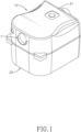
Fig. 1 is a perspective view of a continuous positive airway pressure device of a preferred embodiment in accordance with the present invention; -
Fig. 2 is another perspective view of the continuous positive airway pressure device inFig. 1 ; -
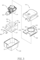
Fig. 3 is an exploded view of the continuous positive airway pressure device inFig. 1 ; -
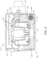
Fig. 4 is a sectional side view of the continuous positive airway pressure device inFig. 1 ; -
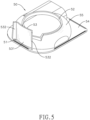
Fig. 5 is a perspective view of a partition of the continuous positive airway pressure device inFig. 1 ; -
Fig. 6 is a partial enlarged view of the partition inFig. 5 ; and -
Figs. 7 to 10 depict a flow path of air in the continuous positive airway pressure device inFig. 1 . - With reference to
Figs. 1 to 3 , a continuous positive airway pressure device of a preferred embodiment in accordance with the present invention has a shell having anupper shell body 10 and alower shell body 20, a diversion sound-absorbingfoam pad 30, ablower 40, apartition 50, and afluid rectifier 60. - With reference to
Figs. 1 to 3 , theupper shell body 10 and thelower shell body 20 are connected to each other to form the shell. The shell encloses an interior space, aninlet 11, and anoutlet 21, and theinlet 11 and theoutlet 21 are respectively located at two opposite sides of the shell. - With reference to
Figs. 3 ,4 ,9 , and10 , the diversion sound-absorbingfoam pad 30 is made of a foam material and has abottom board 31, afirst side wall 32, asecond side wall 33, athird side wall 34, and afourth side wall 35. Thebottom board 31 is disposed inside thelower shell body 20. Thefirst side wall 32, thesecond side wall 33, thethird side wall 34, and thefourth side wall 35 protrude from thebottom board 31, are arranged sequentially, and enclose a containing space of the diversion sound-absorbingfoam pad 30. The diversion sound-absorbingfoam pad 30 has ablower seat 36 protruding from thebottom board 31 and disposed inside the containing space. Theblower seat 36 has anopening 361 recessed on a side of theblower seat 36 near thefourth side wall 35, and theopening 361 extends inward and roughly to a center of theblower seat 36 and fluidly communicates with the containing space of the diversion sound-absorbingfoam pad 30. - With reference to
Figs. 3 ,4 , and8 to 10 , thefirst side wall 32, thesecond side wall 33, thethird side wall 34, and thefourth side wall 35 of the diversion sound-absorbingfoam pad 30, theupper shell body 10, and thelower shell body 20 together enclose an airflow passage. Thefirst side wall 32, thesecond side wall 33, and thefourth side wall 35 are tightly attached to an internal wall of thelower shell body 20. An upper portion of thethird side wall 34 is tightly attached to the internal wall of thelower shell body 20, and a lower end portion of thethird side wall 34 is spaced from the internal wall of thelower shell body 20. The airflow passage extends tortuously inside the shell and around the diversion sound-absorbingfoam pad 30 and sequentially passes by a top surface of thefirst side wall 32, a top surface of thesecond side wall 33, two opposite ends of thethird side wall 34, and thefourth side wall 35. Specifically, the airflow passage extends curvedly from the top surface of thefirst side wall 32 to the top surface of thesecond side wall 33, extends downward from the top surface of thesecond side wall 33, and then bends at one of the two opposite ends of thethird side wall 34; then, the airflow passage extends toward the other one of the two opposite ends of thethird side wall 34, extends from thethird side wall 34 to thefourth side wall 35, and fluidly communicates with theopening 361. - With reference to
Figs. 8 and9 , in the preferred embodiment, the airflow passage hasmultiple flow openings 37, and themultiple flow openings 37 are respectively located between thefirst side wall 32 and the second side wall 33 (an opening for airflow to flow from the top surface of thefirst side wall 32 to the top surface of the second side wall 33), between thesecond side wall 33 and thethird side wall 34, and between thethird side wall 34 and thefourth side wall 35. With reference toFig. 8 , each one of themultiple flow openings 37 is rectangular and has two length edges L and two width edges W. A ratio of a length of said length edge L to a length of said width edge W, simply regarded as a length-width ratio, is preferably between 1:0.4 and 1:0.7, but the present invention is not limited to the above disclosure; configurations of the diversion sound-absorbingfoam pad 30 may change according to needs of users in other embodiments. - With reference to
Figs. 3 and4 , theblower 40 has ablower fluid inlet 41 and ablower fluid outlet 42. Theblower 40 is disposed on theblower seat 36, and theblower fluid inlet 41 of theblower 40 fluidly communicates with theopening 361 of theblower seat 36. Theblower fluid outlet 42 is located through theoutlet 21 of the shell. Theblower 40 is conventional, and thus detailed constructions of theblower 40 are not described. - With reference to
Figs. 3 ,5 , and6 , thepartition 50 has a shape corresponding to a shape of a cover body of theblower 40, and thepartition 50 has a leadinghole 51 and aheat dissipating hole 52 both defined through thepartition 50. Thepartition 50 covers theblower 40 and the diversion sound-absorbingfoam pad 30, and the leadinghole 51 fluidly communicates with theinlet 11 of the shell and a portion of the airflow passage near thefirst side wall 32. In the preferred embodiment, thepartition 50 has adissipating cover 55, a surroundingbottom board 54, and a leadingboard 53. The surroundingbottom board 54 is annularly connected to a surrounding edge of theheat dissipating cover 55, and the leadinghole 51 is defined through the surroundingbottom board 54. The leadingboard 53 protrudes from a position of the surroundingbottom board 54 near the leadinghole 51. - With reference to
Fig. 6 , the leadingboard 53 has two opposite side surfaces, and one of the two opposite side surfaces of the leadingboard 53 is disposed toward the leadinghole 51 and is defined as acentral surface 531. Thecentral surface 531 is a convex surface curved toward the leadinghole 51 and has a central line. The central line is configured to define an imaginary vertical surface I, and a first angle A is defined between the imaginary vertical surface I and the other one of the two opposite side surfaces of the leadingboard 53. The first angle A is preferably between 70 degrees and 89 degrees. The leadingboard 53 has twoend surfaces 532, and each one of the twoend surfaces 532 extends outward from a respective one of two opposite side edges of thecentral surface 531. Each one of the twoend surfaces 532 is configured to define a second angle B between saidend surface 532 and thecentral surface 531, and the second angle B is preferably between 90 degrees and 140 degrees. - With reference to
Figs. 3 and4 , a position of theheat dissipating hole 52 corresponds to a position of theblower 40 and theheat dissipating hole 52 is configured for heat dissipation of theblower 40. Thepartition 50 is fixed on an upper edge of thelower shell body 20 to cover theblower 40 and the diversion sound-absorbingfoam pad 30. In other embodiments, configurations of thepartition 50 and its leadingboard 53 may change according to needs of the users and are not limited to the preferred embodiment. - With reference to
Figs. 3 and4 , thefluid rectifier 60 is a hollow tube and has multiple surroundingwalls 61 disposed in an interior of thefluid rectifier 60. The multiple surroundingwalls 61 are arranged at spaced intervals and divide the interior of thefluid rectifier 60 into multiple passages. The continuous positive airway pressure device further has at least onedetector 62 disposed to thefluid rectifier 60 and configured to detect flow volume and flow velocity of airflow in thefluid rectifier 60. In the preferred embodiment, thefluid rectifier 60 is disposed in the airflow passage and is disposed between the internal wall of thelower shell body 20, thethird side wall 34, and thebottom board 31. In other embodiments, configurations and position of thefluid rectifier 60 may change according to needs of the users and are not limited to the preferred embodiment. - In use of the continuous positive airway pressure device, with reference to
Figs. 1 ,3 , and7 to 10 , direction of airflow is illustrated by arrows in the figures. Theblower 40 makes air outside the shell flow into the continuous positive airway pressure device from theinlet 11 of the shell, and the air is then led by the leadingboard 53 to flow downward into the airflow passage from the leadinghole 51. Afterwards, the air flows by said top surfaces of thefirst side wall 32 and thesecond side wall 33, flows downward through said flow opening 37 between thesecond side wall 33 and thethird side wall 34, and flows into thefluid rectifier 60 from one of two opposite ends of thefluid rectifier 60. Then, the air flows out from the other one of the two opposite ends of thefluid rectifier 60 and flows through theopening 361 near thefourth side wall 36. Finally, the air enters theblower 40 from theblower fluid inlet 41 and flows out from theblower fluid outlet 42. By multiple bends in the flowing path of the air in the continuous positive airway pressure device described above, noises generated while the air flows are apparently reduced, and muting effect of the continuous positive airway pressure device can be improved. - In the above description of the preferred embodiment, the smooth and curved surface on the leading
board 53 and the multiple passages formed inside thefluid rectifier 60 are both configured to adjust airflow and help the air to flow more fluently in the continuous positive airway pressure device of the present invention. - Even though numerous characteristics and advantages of the present invention have been set forth in the foregoing description, together with details of the structure and features of the invention, the disclosure is illustrative only. Changes may be made in the details, especially in matters of shape, size, and arrangement of parts within the principles of the invention to the full extent indicated by the broad general meaning of the terms in which the appended claims are expressed.
Claims (9)
- A continuous positive airway pressure device comprisinga shell havingan upper shell body (10);a lower shell body (20) connected to the upper shell body (10);an interior space; andan inlet (11) and an outlet (21) both fluidly communicating with the interior space of the shell;a diversion sound-absorbing foam pad (30) disposed in the interior space of the shell and havinga bottom board (31);a first side wall (32), a second side wall (33), a third side wall (34), and a fourth side wall (35) protruding from the bottom board (31) and arranged sequentially;a containing space enclosed by the first side wall (32), the second side wall (33), the third side wall (34), and the fourth side wall (35); anda blower seat (36) protruding from the bottom board (31), disposed in the containing space, and having
an opening (361) recessed inward on the blower seat (36), fluidly communicating with the containing space, and disposed near the fourth side wall (35); andwherein the diversion sound-absorbing foam pad (30) forms an airflow passage, and the airflow passage extends tortuously inside the shell and around the diversion sound-absorbing foam pad (30), sequentially passes by a top surface of the first side wall (32), a top surface of the second side wall (33), two opposite ends of the third side wall (34), and the fourth side wall (35), and fluidly communicates with the opening (361);a blower (40) disposed in the containing space, disposed on the blower seat (36), and havinga blower fluid inlet (41) fluidly communicating with the opening (361) of the blower seat (36) of the diversion sound-absorbing foam pad (30); anda blower fluid outlet (42) fluidly communicating with the outlet (21) of the shell; anda partition (50) fixed on a top edge of the lower shell body (20), covering the blower (40) and the diversion sound-absorbing foam pad (30), and having
a leading hole (51) defined through the partition (50), fluidly communicating with a portion of the airflow passage near the first side wall (32), and fluidly communicating with the inlet (11) of the shell. - The continuous positive airway pressure device as claimed in claim 1, whereinthe partition (50) hasa heat dissipating cover (55) having a surrounding edge;a surrounding bottom board (54) annularly connected to the surrounding edge; anda leading board (53) protruding from a position of the surrounding bottom board (54) near the leading hole (51);the leading hole (51) is disposed on the surrounding bottom board (54); andthe leading hole (51) and the inlet (11) of the shell are both disposed on a side of the continuous positive airway pressure device.
- The continuous positive airway pressure device as claimed in claim 2, whereinthe leading board (53) has two opposite side surfaces;one of the two opposite side surfaces of the leading board (53) is disposed toward the leading hole (51), is defined as a central surface (531), and is a convex surface curved toward the leading hole (51);the central surface (531) has a central line configured to define an imaginary vertical surface (I); anda first angle (A) is defined between the imaginary vertical surface (I) and the other one of the two opposite side surfaces of the leading board (53) and is between 70 degrees and 89 degrees.
- The continuous positive airway pressure device as claimed in claim 3, whereinthe leading board (53) has two end surfaces (532);the central surface (531) is disposed between the two end surfaces (532);each one of the two end surfaces (532) extends outward from a respective one of two opposite side edges of the central surface (531);each one of the two end surfaces (532) is configured to define a second angle (B) between the central surface (531) and said end surface; andthe second angle (B) is between 90 degrees and 140 degrees.
- The continuous positive airway pressure device as claimed in any one of claims 1 to 4, wherein the continuous positive airway pressure device has a fluid rectifier (60) being a hollow tube and disposed in the airflow passage.
- The continuous positive airway pressure device as claimed in claim 5, whereinthe fluid rectifier (60) has multiple surrounding walls (61) disposed in an interior of the fluid rectifier (60); andthe multiple surrounding walls (61) are arranged at spaced intervals and divide the interior of the fluid rectifier (60) into multiple passages.
- The continuous positive airway pressure device as claimed in claim 6, wherein the continuous positive airway pressure device has at least one detector (62) disposed to the fluid rectifier (60) and configured to detect a flow volume and a flow velocity of an airflow in the fluid rectifier (60).
- The continuous positive airway pressure device as claimed in claim 2, whereinthe partition (50) has a heat dissipating hole (52) defined through the partition (50); anda position of the heat dissipating hole (52) corresponds to a position of the blower (40).
- The continuous positive airway pressure device as claimed in claim 1, whereinthe airflow passage has multiple flow openings (37);the multiple flow openings (37) are respectively located between the first side wall (32) and the second side wall (33), between the second side wall (33) and the third side wall (34), and between the third side wall (34) and the fourth side wall (35); andeach one of the multiple flow openings (37) is rectangular and has a length-width ratio between 1:0.4 and 1:0.7.
Applications Claiming Priority (1)
| Application Number | Priority Date | Filing Date | Title |
|---|---|---|---|
| TW111204032U TWM630004U (en) | 2022-04-20 | 2022-04-20 | Micro respirator |
Publications (3)
| Publication Number | Publication Date |
|---|---|
| EP4265290A1 EP4265290A1 (en) | 2023-10-25 |
| EP4265290B1 true EP4265290B1 (en) | 2024-07-17 |
| EP4265290C0 EP4265290C0 (en) | 2024-07-17 |
Family
ID=83437999
Family Applications (1)
| Application Number | Title | Priority Date | Filing Date |
|---|---|---|---|
| EP23168675.9A Active EP4265290B1 (en) | 2022-04-20 | 2023-04-19 | Continuous positive airway pressure device |
Country Status (3)
| Country | Link |
|---|---|
| EP (1) | EP4265290B1 (en) |
| JP (1) | JP3242490U (en) |
| TW (1) | TWM630004U (en) |
Family Cites Families (5)
| Publication number | Priority date | Publication date | Assignee | Title |
|---|---|---|---|---|
| AUPP015097A0 (en) * | 1997-11-03 | 1997-11-27 | Resmed Limited | A mounting body |
| US20090007912A1 (en) * | 2004-04-05 | 2009-01-08 | Breas Medical Ab | Ventilator for Supplying Breathable Gas to a Patient, and a Noise Reduction Method for Said Ventilator |
| DE202011101554U1 (en) * | 2010-08-11 | 2011-11-16 | Sls Medical Technology Corp., Ltd. | Ventilator for identifying the purity / turbidity of a filter |
| JP2016034410A (en) * | 2014-08-04 | 2016-03-17 | 日本電産コパル電子株式会社 | Cpap apparatus |
| WO2020121255A1 (en) * | 2018-12-13 | 2020-06-18 | ResMed Pty Ltd | Pneumatic block for respiratory pressure therapy device |
-
2022
- 2022-04-20 TW TW111204032U patent/TWM630004U/en unknown
-
2023
- 2023-04-18 JP JP2023001303U patent/JP3242490U/en active Active
- 2023-04-19 EP EP23168675.9A patent/EP4265290B1/en active Active
Also Published As
| Publication number | Publication date |
|---|---|
| JP3242490U (en) | 2023-06-21 |
| US20230338678A1 (en) | 2023-10-26 |
| EP4265290A1 (en) | 2023-10-25 |
| EP4265290C0 (en) | 2024-07-17 |
| TWM630004U (en) | 2022-07-21 |
Similar Documents
| Publication | Publication Date | Title |
|---|---|---|
| US12214229B2 (en) | Mask apparatus | |
| JP6338487B2 (en) | CPAP equipment | |
| TWI577401B (en) | Humidifier for respiratory apparatus | |
| CN106456925A (en) | Cpap device | |
| CN117404338A (en) | A low noise amortization case for breathing machine | |
| CN115591069A (en) | Air duct assembly of ventilator and portable ventilator | |
| US12629489B2 (en) | Continuous positive airway pressure device | |
| EP4265290A1 (en) | Continuous positive airway pressure device | |
| JP7688519B2 (en) | Gas meter | |
| CN216961539U (en) | A cigarette bullet and electron cigarette for electron cigarette | |
| TWM481735U (en) | Humidifier and breathing apparatus using the same | |
| CN118462661A (en) | Low noise ventilator fan case | |
| JPH10129588A (en) | Regulator for underwater breathing device | |
| US20240016225A1 (en) | Vaporization apparatus applied to e-cigarette and e-cigarette having same | |
| CN219271849U (en) | Turbine box device and breathing machine | |
| CN217176994U (en) | Micro respirator | |
| JP2009030857A (en) | Fan filter unit | |
| WO2023142589A1 (en) | Atomization device for electronic cigarettes and electronic cigarette having same | |
| CN223165718U (en) | air conditioner | |
| CN209347874U (en) | Humidify component and ventilation therapy equipment | |
| JP2001021169A (en) | Integrated air conditioner | |
| CN106801988A (en) | For the denoising device and air processor of air processor | |
| JP2004003883A (en) | Flowmeter | |
| CN221278054U (en) | Low-noise turbine fan | |
| EP4295714A1 (en) | Atomizer for electronic cigarette, and cartridge and electronic cigarette having the same |
Legal Events
| Date | Code | Title | Description |
|---|---|---|---|
| STAA | Information on the status of an ep patent application or granted ep patent |
Free format text: STATUS: THE APPLICATION HAS BEEN PUBLISHED |
|
| PUAI | Public reference made under article 153(3) epc to a published international application that has entered the european phase |
Free format text: ORIGINAL CODE: 0009012 |
|
| AK | Designated contracting states |
Kind code of ref document: A1 Designated state(s): AL AT BE BG CH CY CZ DE DK EE ES FI FR GB GR HR HU IE IS IT LI LT LU LV MC ME MK MT NL NO PL PT RO RS SE SI SK SM TR |
|
| STAA | Information on the status of an ep patent application or granted ep patent |
Free format text: STATUS: REQUEST FOR EXAMINATION WAS MADE |
|
| 17P | Request for examination filed |
Effective date: 20231116 |
|
| RBV | Designated contracting states (corrected) |
Designated state(s): AL AT BE BG CH CY CZ DE DK EE ES FI FR GB GR HR HU IE IS IT LI LT LU LV MC ME MK MT NL NO PL PT RO RS SE SI SK SM TR |
|
| GRAP | Despatch of communication of intention to grant a patent |
Free format text: ORIGINAL CODE: EPIDOSNIGR1 |
|
| STAA | Information on the status of an ep patent application or granted ep patent |
Free format text: STATUS: GRANT OF PATENT IS INTENDED |
|
| RIC1 | Information provided on ipc code assigned before grant |
Ipc: A61M 16/00 20060101AFI20240304BHEP |
|
| INTG | Intention to grant announced |
Effective date: 20240319 |
|
| GRAS | Grant fee paid |
Free format text: ORIGINAL CODE: EPIDOSNIGR3 |
|
| GRAA | (expected) grant |
Free format text: ORIGINAL CODE: 0009210 |
|
| STAA | Information on the status of an ep patent application or granted ep patent |
Free format text: STATUS: THE PATENT HAS BEEN GRANTED |
|
| AK | Designated contracting states |
Kind code of ref document: B1 Designated state(s): AL AT BE BG CH CY CZ DE DK EE ES FI FR GB GR HR HU IE IS IT LI LT LU LV MC ME MK MT NL NO PL PT RO RS SE SI SK SM TR |
|
| REG | Reference to a national code |
Ref country code: CH Ref legal event code: EP |
|
| REG | Reference to a national code |
Ref country code: DE Ref legal event code: R096 Ref document number: 602023000248 Country of ref document: DE |
|
| REG | Reference to a national code |
Ref country code: IE Ref legal event code: FG4D |
|
| U01 | Request for unitary effect filed |
Effective date: 20240717 |
|
| U07 | Unitary effect registered |
Designated state(s): AT BE BG DE DK EE FI FR IT LT LU LV MT NL PT SE SI Effective date: 20240724 |
|
| PG25 | Lapsed in a contracting state [announced via postgrant information from national office to epo] |
Ref country code: NO Free format text: LAPSE BECAUSE OF FAILURE TO SUBMIT A TRANSLATION OF THE DESCRIPTION OR TO PAY THE FEE WITHIN THE PRESCRIBED TIME-LIMIT Effective date: 20241017 |
|
| PG25 | Lapsed in a contracting state [announced via postgrant information from national office to epo] |
Ref country code: GR Free format text: LAPSE BECAUSE OF FAILURE TO SUBMIT A TRANSLATION OF THE DESCRIPTION OR TO PAY THE FEE WITHIN THE PRESCRIBED TIME-LIMIT Effective date: 20241018 Ref country code: PL Free format text: LAPSE BECAUSE OF FAILURE TO SUBMIT A TRANSLATION OF THE DESCRIPTION OR TO PAY THE FEE WITHIN THE PRESCRIBED TIME-LIMIT Effective date: 20240717 |
|
| PG25 | Lapsed in a contracting state [announced via postgrant information from national office to epo] |
Ref country code: IS Free format text: LAPSE BECAUSE OF FAILURE TO SUBMIT A TRANSLATION OF THE DESCRIPTION OR TO PAY THE FEE WITHIN THE PRESCRIBED TIME-LIMIT Effective date: 20241117 |
|
| PG25 | Lapsed in a contracting state [announced via postgrant information from national office to epo] |
Ref country code: HR Free format text: LAPSE BECAUSE OF FAILURE TO SUBMIT A TRANSLATION OF THE DESCRIPTION OR TO PAY THE FEE WITHIN THE PRESCRIBED TIME-LIMIT Effective date: 20240717 |
|
| PG25 | Lapsed in a contracting state [announced via postgrant information from national office to epo] |
Ref country code: ES Free format text: LAPSE BECAUSE OF FAILURE TO SUBMIT A TRANSLATION OF THE DESCRIPTION OR TO PAY THE FEE WITHIN THE PRESCRIBED TIME-LIMIT Effective date: 20240717 Ref country code: RS Free format text: LAPSE BECAUSE OF FAILURE TO SUBMIT A TRANSLATION OF THE DESCRIPTION OR TO PAY THE FEE WITHIN THE PRESCRIBED TIME-LIMIT Effective date: 20241017 |
|
| PG25 | Lapsed in a contracting state [announced via postgrant information from national office to epo] |
Ref country code: RS Free format text: LAPSE BECAUSE OF FAILURE TO SUBMIT A TRANSLATION OF THE DESCRIPTION OR TO PAY THE FEE WITHIN THE PRESCRIBED TIME-LIMIT Effective date: 20241017 Ref country code: PL Free format text: LAPSE BECAUSE OF FAILURE TO SUBMIT A TRANSLATION OF THE DESCRIPTION OR TO PAY THE FEE WITHIN THE PRESCRIBED TIME-LIMIT Effective date: 20240717 Ref country code: NO Free format text: LAPSE BECAUSE OF FAILURE TO SUBMIT A TRANSLATION OF THE DESCRIPTION OR TO PAY THE FEE WITHIN THE PRESCRIBED TIME-LIMIT Effective date: 20241017 Ref country code: IS Free format text: LAPSE BECAUSE OF FAILURE TO SUBMIT A TRANSLATION OF THE DESCRIPTION OR TO PAY THE FEE WITHIN THE PRESCRIBED TIME-LIMIT Effective date: 20241117 Ref country code: HR Free format text: LAPSE BECAUSE OF FAILURE TO SUBMIT A TRANSLATION OF THE DESCRIPTION OR TO PAY THE FEE WITHIN THE PRESCRIBED TIME-LIMIT Effective date: 20240717 Ref country code: GR Free format text: LAPSE BECAUSE OF FAILURE TO SUBMIT A TRANSLATION OF THE DESCRIPTION OR TO PAY THE FEE WITHIN THE PRESCRIBED TIME-LIMIT Effective date: 20241018 Ref country code: ES Free format text: LAPSE BECAUSE OF FAILURE TO SUBMIT A TRANSLATION OF THE DESCRIPTION OR TO PAY THE FEE WITHIN THE PRESCRIBED TIME-LIMIT Effective date: 20240717 |
|
| U20 | Renewal fee for the european patent with unitary effect paid |
Year of fee payment: 3 Effective date: 20250220 |
|
| PG25 | Lapsed in a contracting state [announced via postgrant information from national office to epo] |
Ref country code: SM Free format text: LAPSE BECAUSE OF FAILURE TO SUBMIT A TRANSLATION OF THE DESCRIPTION OR TO PAY THE FEE WITHIN THE PRESCRIBED TIME-LIMIT Effective date: 20240717 |
|
| PG25 | Lapsed in a contracting state [announced via postgrant information from national office to epo] |
Ref country code: CZ Free format text: LAPSE BECAUSE OF FAILURE TO SUBMIT A TRANSLATION OF THE DESCRIPTION OR TO PAY THE FEE WITHIN THE PRESCRIBED TIME-LIMIT Effective date: 20240717 |
|
| PG25 | Lapsed in a contracting state [announced via postgrant information from national office to epo] |
Ref country code: SK Free format text: LAPSE BECAUSE OF FAILURE TO SUBMIT A TRANSLATION OF THE DESCRIPTION OR TO PAY THE FEE WITHIN THE PRESCRIBED TIME-LIMIT Effective date: 20240717 |
|
| PLBE | No opposition filed within time limit |
Free format text: ORIGINAL CODE: 0009261 |
|
| STAA | Information on the status of an ep patent application or granted ep patent |
Free format text: STATUS: NO OPPOSITION FILED WITHIN TIME LIMIT |
|
| 26N | No opposition filed |
Effective date: 20250422 |
|
| PG25 | Lapsed in a contracting state [announced via postgrant information from national office to epo] |
Ref country code: MC Free format text: LAPSE BECAUSE OF FAILURE TO SUBMIT A TRANSLATION OF THE DESCRIPTION OR TO PAY THE FEE WITHIN THE PRESCRIBED TIME-LIMIT Effective date: 20240717 |
|
| PG25 | Lapsed in a contracting state [announced via postgrant information from national office to epo] |
Ref country code: IE Free format text: LAPSE BECAUSE OF NON-PAYMENT OF DUE FEES Effective date: 20250419 |
|
| PG25 | Lapsed in a contracting state [announced via postgrant information from national office to epo] |
Ref country code: RO Free format text: LAPSE BECAUSE OF FAILURE TO SUBMIT A TRANSLATION OF THE DESCRIPTION OR TO PAY THE FEE WITHIN THE PRESCRIBED TIME-LIMIT Effective date: 20240717 |
|
| U20 | Renewal fee for the european patent with unitary effect paid |
Year of fee payment: 4 Effective date: 20260311 |