EP4265179A1 - Electrical impedance imaging method, system, storage medium, and electronic device - Google Patents
Electrical impedance imaging method, system, storage medium, and electronic device Download PDFInfo
- Publication number
- EP4265179A1 EP4265179A1 EP21881677.5A EP21881677A EP4265179A1 EP 4265179 A1 EP4265179 A1 EP 4265179A1 EP 21881677 A EP21881677 A EP 21881677A EP 4265179 A1 EP4265179 A1 EP 4265179A1
- Authority
- EP
- European Patent Office
- Prior art keywords
- image
- matrix
- electrical impedance
- covariance matrix
- basis
- Prior art date
- Legal status (The legal status is an assumption and is not a legal conclusion. Google has not performed a legal analysis and makes no representation as to the accuracy of the status listed.)
- Granted
Links
Images

Classifications
-
- A—HUMAN NECESSITIES
- A61—MEDICAL OR VETERINARY SCIENCE; HYGIENE
- A61B—DIAGNOSIS; SURGERY; IDENTIFICATION
- A61B5/00—Measuring for diagnostic purposes; Identification of persons
- A61B5/05—Detecting, measuring or recording for diagnosis by means of electric currents or magnetic fields; Measuring using microwaves or radio waves
- A61B5/053—Measuring electrical impedance or conductance of a portion of the body
- A61B5/0536—Impedance imaging, e.g. by tomography
-
- A—HUMAN NECESSITIES
- A61—MEDICAL OR VETERINARY SCIENCE; HYGIENE
- A61B—DIAGNOSIS; SURGERY; IDENTIFICATION
- A61B5/00—Measuring for diagnostic purposes; Identification of persons
- A61B5/02—Detecting, measuring or recording for evaluating the cardiovascular system, e.g. pulse, heart rate, blood pressure or blood flow
- A61B5/026—Measuring blood flow
-
- A—HUMAN NECESSITIES
- A61—MEDICAL OR VETERINARY SCIENCE; HYGIENE
- A61B—DIAGNOSIS; SURGERY; IDENTIFICATION
- A61B5/00—Measuring for diagnostic purposes; Identification of persons
- A61B5/08—Measuring devices for evaluating the respiratory organs
-
- A—HUMAN NECESSITIES
- A61—MEDICAL OR VETERINARY SCIENCE; HYGIENE
- A61B—DIAGNOSIS; SURGERY; IDENTIFICATION
- A61B2576/00—Medical imaging apparatus involving image processing or analysis
- A61B2576/02—Medical imaging apparatus involving image processing or analysis specially adapted for a particular organ or body part
Definitions
- the present disclosure pertains to the field of electrical impedance imaging technology, and in particular relates to a method, a system, a storage medium, and an electronic device for electrical impedance imaging.
- the present disclosure presents a method, a system, a storage medium, and an electronic device for electrical impedance imaging, precisely based on the technical problem that it is difficult to reflect the overall state of a tested human body through instantaneous electrical impedance change images.
- the present disclosure provides an electrical impedance imaging method, comprising: acquiring electrical impedance measurement signals of a tested human body area at a plurality of measurement times; for the electrical impedance measurement signal at each measurement time, constructing a corresponding instantaneous differential image on the basis of the electrical impedance measurement signal; constructing an image matrix on the basis of the instantaneous differential images at the plurality of measurement times, wherein each column in the image matrix is a vector corresponding to respective instantaneous differential image; determining, on the basis of the image matrix, a covariance matrix corresponding to the image matrix; obtaining, according to the covariance matrix, a weight vector of the covariance matrix; and obtaining, on the basis of the covariance matrix and the weight vector, an electrical impedance state image of the tested human body area.
- I is the image matrix
- a ( t 1 ) is a vector corresponding to the instantaneous differential image at a first measurement time
- a ( t 2 ) is a vector corresponding to the instantaneous differential image at a second measurement time
- a ( t N ) is a vector corresponding to the instantaneous differential image at an N-th measurement time.
- the for the electrical impedance measurement signal at each measurement time, constructing a corresponding instantaneous differential image on the basis of electrical impedance measurement signal further comprises: for the electrical impedance measurement signal at each measurement time, extracting a signal in a predetermined frequency range from the electrical impedance measurement signal; and for each extracted signal in the predetermined frequency range, constructing a corresponding instantaneous differential image on the basis of the extracted signal in the predetermined frequency range by using an image reconstruction algorithm.
- the image reconstruction algorithm comprises a linear least square method.
- an electrical impedance imaging system comprising: an acquisition module, configured to acquire electrical impedance measurement signals of a tested human body area at a plurality of measurement times; an image construction module, configured to construct, for the electrical impedance measurement signal at each measurement time, a corresponding instantaneous differential image on the basis of the electrical impedance measurement signal; a matrix construction module, configured to construct an image matrix on the basis of the instantaneous differential images at the plurality of measurement times, wherein each column in the image matrix is a vector corresponding to respective instantaneous differential image; a covariance matrix calculation module, configured to determine, on the basis of the image matrix, a covariance matrix corresponding to the image matrix; a weight vector calculation module, configured to obtain, according to the covariance matrix, a weight vector of the covariance matrix; and a state image construction module, configured to obtain, on the basis of the covariance matrix and the weight vector, an electrical impedance state image of the tested human body area.
- the present disclosure provides a storage medium having program code stored thereon, wherein the electrical impedance imaging method as described in any of the above examples is implemented when the program code is executed by a processor.
- the present disclosure provides an electronic device, comprising a memory and a processor, wherein program code runnable on the processor is stored on the memory, and wherein the electrical impedance imaging method as described in any of the above examples is implemented when the program code is executed by the processor.
- an electrical impedance state image which reflects the overall state of a tested human body function over a period of time, is reconstructed from the electrical impedance measurement signals of the tested human body area at a plurality of measurement times.
- the electrical impedance imaging method provided in the present disclosure can be used to obtain an electrical impedance state image that reflects the overall state of the tested human body function over a period of time, thereby facilitating the understanding of images and the overall grasp of the tested human body function by an observer for subsequent qualitative and quantitative analysis of the tested human body function.
- FIG. 1 illustrates a schematic flow diagram of an electrical impedance imaging method provided in Example 1.
- the electrical impedance imaging method may include steps S110 to S160 as follows.
- step S110 electrical impedance measurement signals of a tested human body area is acquired at a plurality of measurement times.
- the electrical impedance measurement requires first fixing an electrode array containing a number of electrodes around the tested human body area, and then exciting the tested human body area by the electrode array and measuring the resulting response.
- the electrical impedance measurement signals are obtained by applying current excitation to the electrodes in turn and successively measuring the resulting voltage signals at other electrodes.
- the plurality of measurement times means that the electrical impedance measurement is performed on the tested human body area several times over a continuous period of time, thereby obtaining the electrical impedance measurement signals at the plurality of measurement times.
- step S120 for the electrical impedance measurement signal at each measurement time, a corresponding instantaneous differential image is conducted on the basis of the electrical impedance measurement signal.
- the corresponding instantaneous differential image can be constructed on the basis of the electrical impedance measurement signal. If there are five measurement times, the instantaneous differential image corresponding to each of the five measurement times can be obtained.
- the instantaneous differential image reflects the change in electrical impedance of the tested human body area at the measurement time of the reconstruction of the instantaneous differential image with respect to a reference time (e.g., the time corresponding to the end of expiration).
- step S120 for the electrical impedance measurement signal at each measurement time, constructing a corresponding instantaneous differential image on the basis of the electrical impedance measurement signal, comprises steps S121 to S122 as follows.
- Step S121 for each electrical impedance measurement signal at each measurement time, a signal in a predetermined frequency range is extracted from the electrical impedance measurement signal.
- Step S122 for each extracted signal in the predetermined frequency range, a corresponding instantaneous differential image is constructed on the basis of the extracted signal in the predetermined frequency range by using an image reconstruction algorithm.
- a signal in the predetermined frequency range is extracted from the electrical impedance measurement signals on the basis of the time-frequency characteristics of signals.
- the predetermined frequency range may be in a ventilation frequency range, then the extracted signal is a ventilation-related signal; and the predetermined frequency range may be in a blood perfusion frequency range, then the extracted signal is a blood perfusion-related signal.
- a signal in the predetermined frequency range can be extracted from the electrical impedance measurement signals by using a filter.
- the signal in the predetermined frequency range is used to construct a instantaneous differential image by an image reconstruction algorithm.
- the image reconstruction algorithm may be a differential reconstruction algorithm, such as a linear least square method.
- the reconstruction process may be as follows: extracting a signal in a predetermined frequency range, i.e., a blood perfusion-related signal, from the electrical impedance measurement signals, and then performing the image reconstruction by using an image reconstruction algorithm on the basis of this blood perfusion-related signal to obtain a blood perfusion image.
- a signal in a predetermined frequency range i.e., a blood perfusion-related signal
- step S130 an image matrix is constructed on the basis of the instantaneous differential images at the plurality of measurement times.
- Each column in the image matrix is a vector corresponding to respective instantaneous differential image.
- the image matrix is constructed by using the instantaneous differential images corresponding to the plurality of measurement times.
- step S140 a covariance matrix corresponding to the image matrix is determined on the basis of the image matrix.
- a covariance matrix of this image matrix can be calculated after the image matrix is constructed.
- the determining of a covariance matrix corresponding to the image matrix on the basis of the image matrix further comprises the following process.
- Each element in the vector a ( t i ) represents a pixel value in the image.
- a covariance matrix of the image matrix can be calculated by the first predetermined computational equation.
- step S150 according to the covariance matrix, a weight vector of the covariance matrix is obtained.
- the obtaining of a weight vector of the covariance matrix according to the covariance matrix further comprises the following process.
- the solution of the weight vector w ⁇ is actually to solve the 0-1 quadratic programming problem.
- M is the total number of pixels in the image.
- step S 160 on the basis of the covariance matrix and the weight vector, an electrical impedance state image of the tested human body area is obtained.
- the obtaining of an electrical impedance state image of the tested human body area on the basis of the covariance matrix and the weight vector further comprises the following process.
- the electrical impedance state image can reflect the overall state of the tested human body area over a period of time, thus facilitating the understanding of the images and the overall grasp of the tested human body function by an observer, and thus facilitating subsequent qualitative and quantitative analysis of the tested human body function.
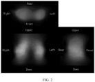
- Figure 2 illustrates an effect picture of the electrical impedance state image of three-dimensional blood perfusion in a human thoracic cavity.
- the electrical impedance state image reflects the electrical impedance state of three-dimensional blood perfusion in the human thoracic cavity for a period of time. Based on this image, it is easy for an observer to understand the image and grasp the overall situation of blood perfusion in the tested human body, which facilitates the subsequent qualitative and quantitative analysis of the tested human body function.
- an electrical impedance imaging system which comprises an acquisition module, an image construction module, a matrix construction module, a covariance matrix calculation module, a weight vector calculation module, and a state image construction module.
- the acquisition module is configured to acquire electrical impedance measurement signals of a tested human body area at a plurality of measurement times.
- the image construction module is configured to construct, for the electrical impedance measurement signal at each measurement time, a corresponding instantaneous differential image on the basis of the electrical impedance measurement signal.
- the matrix construction module is configured to construct an image matrix on the basis of the instantaneous differential images at the plurality of measurement times, wherein each column in the image matrix is a vector corresponding to respective instantaneous differential image.
- the covariance matrix calculation module is configured to determine a covariance matrix corresponding to the image matrix on the basis of the image matrix.
- the weight vector calculation module is configured to obtain a weight vector of this covariance matrix according to the covariance matrix.
- the state image construction module is configured to obtain an electrical impedance state image of the tested human body area on the basis of the covariance matrix and the weight vector.
- a storage medium having program code stored thereon is also provided, wherein the electrical impedance imaging method as described in any of the above examples is implemented when the program code is executed by a processor.
- an electronic device comprising a memory and a processor
- program code runnable on the processor is stored on the memory
- the electrical impedance imaging method as described in any of the above examples is implemented when the program code is executed by the processor.
- the present disclosure provides an electrical impedance imaging method, a system, a storage medium, and an electronic device, an electrical impedance state image reflecting the overall state of the tested human body function over a period of time is reconstructed from electrical impedance measurement signals of the tested human body area at a plurality of measurement times.
- an electrical impedance state image reflecting the overall state of the tested human body function over a period of time can be obtained by using the electrical impedance imaging method provided by the examples of the present disclosure, thereby facilitating the understanding of the images and the overall grasp of the tested human body function by an observer for subsequent qualitative and quantitative analysis of the tested human body function.
- the disclosed device and method can be implemented in other ways.
- the device examples described above are merely schematic, e.g., the division of units, which is only a logical functional division, can be performed in other ways in actual implementation.
- a plurality of units or assemblies can be combined or integrated into another system, or some features can be ignored, or not implemented.
- the units illustrated as isolated components may or may not be physically separated, and the components displayed as units may or may not be physical units, i.e. they may be located in one position or may be distributed to a plurality of network units. Some or all of these units may be selected based on practical needs to achieve the purpose of examples in the present disclosure.
- each functional unit in each example of the present disclosure may be integrated in a single processing unit, or each functional unit may be present in physical separation, or two or more units may be integrated in a single processing unit.
- the above integrated units can be implemented in the form of either hardware or software functional units.
- the integrated unit when implemented in the form of software functional units and sold or used as a separate product, may be stored in a computer readable storage medium.
- the software product is stored in a storage medium and includes a number of instructions to enable an electronic device (which may be a personal computer, a server, or a network device, etc.) to perform all or some of the steps in various examples of the present disclosure.
- the aforementioned storage medium includes: USB flash drives, portable hard drives, Read-Only Memories (ROM), Random Access Memories (RAM), disks, or compact discs, and various other media that can store a program code.
Landscapes
- Health & Medical Sciences (AREA)
- Life Sciences & Earth Sciences (AREA)
- Nuclear Medicine, Radiotherapy & Molecular Imaging (AREA)
- Medical Informatics (AREA)
- Surgery (AREA)
- Biophysics (AREA)
- Pathology (AREA)
- Engineering & Computer Science (AREA)
- Biomedical Technology (AREA)
- Heart & Thoracic Surgery (AREA)
- Veterinary Medicine (AREA)
- Molecular Biology (AREA)
- Physics & Mathematics (AREA)
- Animal Behavior & Ethology (AREA)
- General Health & Medical Sciences (AREA)
- Public Health (AREA)
- Radiology & Medical Imaging (AREA)
- Physiology (AREA)
- Hematology (AREA)
- Cardiology (AREA)
- Pulmonology (AREA)
- Measurement And Recording Of Electrical Phenomena And Electrical Characteristics Of The Living Body (AREA)
- Measurement Of The Respiration, Hearing Ability, Form, And Blood Characteristics Of Living Organisms (AREA)
Abstract
Description
- This application claims the priority of the Chinese patent application
CN202011145265.2 entitled "Electrical Impedance Imaging Method, System, Storage Medium and Electronic Device", filed on October 23, 2020 - The present disclosure pertains to the field of electrical impedance imaging technology, and in particular relates to a method, a system, a storage medium, and an electronic device for electrical impedance imaging.
- Current electrical impedance imaging techniques can only produce instantaneous electrical impedance change images, such as ones caused by instantaneous ventilation or blood perfusion. However, the instantaneous electrical impedance change images, such as blood perfusion images, change rapidly when displayed, which is detrimental to the understanding of the image by an observer. Moreover, the instantaneous electrical impedance change images often show relatively large differences in different human physiological cycles (e.g.,the cardiac cycle), making it difficult for the observer to understand the overall functional state (e.g., ventilation or blood perfusion) of a tested human body area over a period of time.
- The present disclosure presents a method, a system, a storage medium, and an electronic device for electrical impedance imaging, precisely based on the technical problem that it is difficult to reflect the overall state of a tested human body through instantaneous electrical impedance change images.
- In a first aspect, the present disclosure provides an electrical impedance imaging method, comprising: acquiring electrical impedance measurement signals of a tested human body area at a plurality of measurement times; for the electrical impedance measurement signal at each measurement time, constructing a corresponding instantaneous differential image on the basis of the electrical impedance measurement signal; constructing an image matrix on the basis of the instantaneous differential images at the plurality of measurement times, wherein each column in the image matrix is a vector corresponding to respective instantaneous differential image; determining, on the basis of the image matrix, a covariance matrix corresponding to the image matrix; obtaining, according to the covariance matrix, a weight vector of the covariance matrix; and obtaining, on the basis of the covariance matrix and the weight vector, an electrical impedance state image of the tested human body area.
- Optionally, the image matrix is:

- Optionally, the determining, on the basis of the image matrix, a covariance matrix corresponding to the image matrix, further comprises: calculating, on the basis of the image matrix, the covariance matrix corresponding to the image matrix by using a first predetermined computational equation, wherein, the first predetermined computational equation is:

I is a time-averaged matrix with the size of M ∗ N, and each column element in the time-averaged matrix is
- Optionally, the obtaining, according to the covariance matrix, a weight vector of the covariance matrix, further comprises: calculating the weight vector of the covariance matrix according to the covariance matrix by using a second predetermined computational equation, wherein the second predetermined computational equation is:

- Optionally, the obtaining, on the basis of the covariance matrix and the weight vector, an electrical impedance state image of the tested human body area, further comprises: calculating, on the basis of the covariance matrix and the weight vector, the electrical impedance state image of the tested human body area by using a third predetermined computational equation, wherein the third predetermined computational equation is:

- Optionally, the for the electrical impedance measurement signal at each measurement time, constructing a corresponding instantaneous differential image on the basis of electrical impedance measurement signal, further comprises: for the electrical impedance measurement signal at each measurement time, extracting a signal in a predetermined frequency range from the electrical impedance measurement signal; and for each extracted signal in the predetermined frequency range, constructing a corresponding instantaneous differential image on the basis of the extracted signal in the predetermined frequency range by using an image reconstruction algorithm.
- Optionally, the image reconstruction algorithm comprises a linear least square method.
- In a second aspect, the present disclosure provides an electrical impedance imaging system comprising: an acquisition module, configured to acquire electrical impedance measurement signals of a tested human body area at a plurality of measurement times; an image construction module, configured to construct, for the electrical impedance measurement signal at each measurement time, a corresponding instantaneous differential image on the basis of the electrical impedance measurement signal; a matrix construction module, configured to construct an image matrix on the basis of the instantaneous differential images at the plurality of measurement times, wherein each column in the image matrix is a vector corresponding to respective instantaneous differential image; a covariance matrix calculation module, configured to determine, on the basis of the image matrix, a covariance matrix corresponding to the image matrix; a weight vector calculation module, configured to obtain, according to the covariance matrix, a weight vector of the covariance matrix; and a state image construction module, configured to obtain, on the basis of the covariance matrix and the weight vector, an electrical impedance state image of the tested human body area.
- In a third aspect, the present disclosure provides a storage medium having program code stored thereon, wherein the electrical impedance imaging method as described in any of the above examples is implemented when the program code is executed by a processor.
- In the fourth aspect, the present disclosure provides an electronic device, comprising a memory and a processor, wherein program code runnable on the processor is stored on the memory, and wherein the electrical impedance imaging method as described in any of the above examples is implemented when the program code is executed by the processor.
- In the method, the system, the storage medium, and the electronic device for electrical impedance imaging provided in the present disclosure, an electrical impedance state image, which reflects the overall state of a tested human body function over a period of time, is reconstructed from the electrical impedance measurement signals of the tested human body area at a plurality of measurement times. As can be seen, the electrical impedance imaging method provided in the present disclosure can be used to obtain an electrical impedance state image that reflects the overall state of the tested human body function over a period of time, thereby facilitating the understanding of images and the overall grasp of the tested human body function by an observer for subsequent qualitative and quantitative analysis of the tested human body function.
- The scope of the present disclosure may be better understood by reading the detailed description of exemplary examples below in conjunction with the drawings. The drawings included herein are:
-
FIG. 1 illustrates a schematic flow diagram of an electrical impedance imaging method provided in Example 1 of the present disclosure; -
FIG. 2 illustrates an effect picture of an electrical impedance state image of three-dimensional blood perfusion in a human thoracic cavity. - In order to make the purpose, technical solutions and advantages of the present disclosure clearer, the implementation method of the present disclosure will be described in detail below in conjunction with the drawings and examples, whereby the implementation process of how technical means can be applied in the present disclosure to solve technical problems and achieve technical effects, can be fully understood and carried out accordingly.
- While many specific details are set forth in the following description to facilitate a full understanding of the present disclosure, the present disclosure may also be implemented in other ways different from those described herein, and therefore the protection scope of the present disclosure is not limited by the specific examples disclosed below.
- According to examples of the present disclosure, an electrical impedance imaging method is provided, and
FIG. 1 illustrates a schematic flow diagram of an electrical impedance imaging method provided in Example 1. As shown inFIG. 1 , the electrical impedance imaging method may include steps S110 to S160 as follows. - In step S110, electrical impedance measurement signals of a tested human body area is acquired at a plurality of measurement times.
- Here, the electrical impedance measurement requires first fixing an electrode array containing a number of electrodes around the tested human body area, and then exciting the tested human body area by the electrode array and measuring the resulting response. For example, the electrical impedance measurement signals are obtained by applying current excitation to the electrodes in turn and successively measuring the resulting voltage signals at other electrodes.
- The plurality of measurement times means that the electrical impedance measurement is performed on the tested human body area several times over a continuous period of time, thereby obtaining the electrical impedance measurement signals at the plurality of measurement times.
- In step S120, for the electrical impedance measurement signal at each measurement time, a corresponding instantaneous differential image is conducted on the basis of the electrical impedance measurement signal.
- Here, after the electrical impedance measurement signal is obtained, the corresponding instantaneous differential image can be constructed on the basis of the electrical impedance measurement signal. If there are five measurement times, the instantaneous differential image corresponding to each of the five measurement times can be obtained.
- The instantaneous differential image reflects the change in electrical impedance of the tested human body area at the measurement time of the reconstruction of the instantaneous differential image with respect to a reference time (e.g., the time corresponding to the end of expiration).
- In an optional embodiment, in step S120, for the electrical impedance measurement signal at each measurement time, constructing a corresponding instantaneous differential image on the basis of the electrical impedance measurement signal, comprises steps S121 to S122 as follows.
- Step S121, for each electrical impedance measurement signal at each measurement time, a signal in a predetermined frequency range is extracted from the electrical impedance measurement signal.
- Step S122, for each extracted signal in the predetermined frequency range, a corresponding instantaneous differential image is constructed on the basis of the extracted signal in the predetermined frequency range by using an image reconstruction algorithm.
- Here, in step S121, a signal in the predetermined frequency range is extracted from the electrical impedance measurement signals on the basis of the time-frequency characteristics of signals. The predetermined frequency range may be in a ventilation frequency range, then the extracted signal is a ventilation-related signal; and the predetermined frequency range may be in a blood perfusion frequency range, then the extracted signal is a blood perfusion-related signal. Specifically, a signal in the predetermined frequency range can be extracted from the electrical impedance measurement signals by using a filter.
- After being extracted, the signal in the predetermined frequency range is used to construct a instantaneous differential image by an image reconstruction algorithm. The image reconstruction algorithm may be a differential reconstruction algorithm, such as a linear least square method.
- It should be understood that although the linear least square method is used as the image reconstruction algorithm to reconstruct the instantaneous differential image in the present embodiment, those skilled in the art should understand that other image reconstruction algorithms may also be used in the present disclosure.
- With the instantaneous differential image reconstruction of thoracic cavity blood perfusion taken as an example, the reconstruction process may be as follows: extracting a signal in a predetermined frequency range, i.e., a blood perfusion-related signal, from the electrical impedance measurement signals, and then performing the image reconstruction by using an image reconstruction algorithm on the basis of this blood perfusion-related signal to obtain a blood perfusion image.
- In step S130, an image matrix is constructed on the basis of the instantaneous differential images at the plurality of measurement times. Each column in the image matrix is a vector corresponding to respective instantaneous differential image.
- Here, after the instantaneous differential images corresponding to the plurality of measurement times are obtained, the image matrix is constructed by using the instantaneous differential images corresponding to the plurality of measurement times. This image matrix is:

- In step S140, a covariance matrix corresponding to the image matrix is determined on the basis of the image matrix.
- Here, a covariance matrix of this image matrix can be calculated after the image matrix is constructed.
- In an optional embodiment, the determining of a covariance matrix corresponding to the image matrix on the basis of the image matrix further comprises the following process.
- On the basis of the image matrix, the covariance matrix corresponding to the image matrix is calculated by using a first predetermined computational equation, wherein the first predetermined computational equation is:

I is a time-averaged matrix with a size of M ∗ N, and each column element in the time-averaged matrix is
- Here, each instantaneous differential image can be expressed as a column vector a(ti ), where ti is an i-th measurement time, i = 1,2, ... , N, and N is the number of measurement times. Each element in the vector a(ti ) represents a pixel value in the image. The image matrix is:I = (a(t 1), a(t 2), ..., a(tN )), and the time-averaged matrix is a matrix with a size of M ∗ N, and each column element in this matrix is
a . Then a covariance matrix of the image matrix can be calculated by the first predetermined computational equation. - In step S150, according to the covariance matrix, a weight vector of the covariance matrix is obtained.
- In an optional embodiment, the obtaining of a weight vector of the covariance matrix according to the covariance matrix further comprises the following process.
- A weight vector of the covariance matrix is obtained according to the covariance matrix by using a second predetermined computational equation, wherein the second predetermined computational equation is:

- Here, the solution of the weight vector w ∗ is actually to solve the 0-1 quadratic programming problem. Wherein, M is the total number of pixels in the image.
- In step S 160, on the basis of the covariance matrix and the weight vector, an electrical impedance state image of the tested human body area is obtained.
- In an optional embodiment, the obtaining of an electrical impedance state image of the tested human body area on the basis of the covariance matrix and the weight vector further comprises the following process.
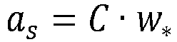
- The electrical impedance state image of the tested human body area is obtained on the basis of the covariance matrix and the weight vector by using a third predetermined computational equation, wherein the third predetermined computational equation is:
- Here, the electrical impedance state image can reflect the overall state of the tested human body area over a period of time, thus facilitating the understanding of the images and the overall grasp of the tested human body function by an observer, and thus facilitating subsequent qualitative and quantitative analysis of the tested human body function.
-
Figure 2 illustrates an effect picture of the electrical impedance state image of three-dimensional blood perfusion in a human thoracic cavity. As shown inFigure 2 , the electrical impedance state image reflects the electrical impedance state of three-dimensional blood perfusion in the human thoracic cavity for a period of time. Based on this image, it is easy for an observer to understand the image and grasp the overall situation of blood perfusion in the tested human body, which facilitates the subsequent qualitative and quantitative analysis of the tested human body function. - According to examples of the present disclosure, an electrical impedance imaging system is also provided, which comprises an acquisition module, an image construction module, a matrix construction module, a covariance matrix calculation module, a weight vector calculation module, and a state image construction module.
- The acquisition module is configured to acquire electrical impedance measurement signals of a tested human body area at a plurality of measurement times.
- The image construction module is configured to construct, for the electrical impedance measurement signal at each measurement time, a corresponding instantaneous differential image on the basis of the electrical impedance measurement signal.
- The matrix construction module is configured to construct an image matrix on the basis of the instantaneous differential images at the plurality of measurement times, wherein each column in the image matrix is a vector corresponding to respective instantaneous differential image.
- The covariance matrix calculation module is configured to determine a covariance matrix corresponding to the image matrix on the basis of the image matrix.
- The weight vector calculation module is configured to obtain a weight vector of this covariance matrix according to the covariance matrix.
- The state image construction module is configured to obtain an electrical impedance state image of the tested human body area on the basis of the covariance matrix and the weight vector.
- According to examples of the present disclosure, a storage medium having program code stored thereon is also provided, wherein the electrical impedance imaging method as described in any of the above examples is implemented when the program code is executed by a processor.
- According to examples of the present disclosure, an electronic device comprising a memory and a processor is also provided, program code runnable on the processor is stored on the memory, and the electrical impedance imaging method as described in any of the above examples is implemented when the program code is executed by the processor.
- The technical solutions of the present disclosure are described in detail above in conjunction with the drawings. Given that instantaneous electrical impedance change images in the related art can hardly reflect the overall state of the tested human body, the present disclosure provides an electrical impedance imaging method, a system, a storage medium, and an electronic device, an electrical impedance state image reflecting the overall state of the tested human body function over a period of time is reconstructed from electrical impedance measurement signals of the tested human body area at a plurality of measurement times. As can be seen, an electrical impedance state image reflecting the overall state of the tested human body function over a period of time can be obtained by using the electrical impedance imaging method provided by the examples of the present disclosure, thereby facilitating the understanding of the images and the overall grasp of the tested human body function by an observer for subsequent qualitative and quantitative analysis of the tested human body function.
- In the several examples provided in the present application, it should be understood that the disclosed device and method can be implemented in other ways. For example, the device examples described above are merely schematic, e.g., the division of units, which is only a logical functional division, can be performed in other ways in actual implementation. For example, a plurality of units or assemblies can be combined or integrated into another system, or some features can be ignored, or not implemented.
- The units illustrated as isolated components may or may not be physically separated, and the components displayed as units may or may not be physical units, i.e. they may be located in one position or may be distributed to a plurality of network units. Some or all of these units may be selected based on practical needs to achieve the purpose of examples in the present disclosure.
- In addition, each functional unit in each example of the present disclosure may be integrated in a single processing unit, or each functional unit may be present in physical separation, or two or more units may be integrated in a single processing unit. The above integrated units can be implemented in the form of either hardware or software functional units.
- The integrated unit, when implemented in the form of software functional units and sold or used as a separate product, may be stored in a computer readable storage medium. Based on this understanding, the essence of the technical solution of the present disclosure, or in other words, a part thereof contributing to the prior art, or all or parts of the technical solution may be embodied in the form of a software product. The software product is stored in a storage medium and includes a number of instructions to enable an electronic device (which may be a personal computer, a server, or a network device, etc.) to perform all or some of the steps in various examples of the present disclosure. The aforementioned storage medium includes: USB flash drives, portable hard drives, Read-Only Memories (ROM), Random Access Memories (RAM), disks, or compact discs, and various other media that can store a program code.
- Although the present disclosure discloses embodiments as described above, the described contents are only embodiments adopted to facilitate the understanding of the present disclosure and are not intended to limit the present disclosure. Those skilled in the art to which the present disclosure pertains may make any modifications and changes in the form and details of implementation without departing from the spirit and scope of the present disclosure. However, the protection scope of the present disclosure shall be still defined in the appended claims.
Claims (13)
- An electrical impedance imaging method, comprising:acquiring electrical impedance measurement signals of a tested human body area at a plurality of measurement times;for the electrical impedance measurement signal at each measurement time, constructing a corresponding instantaneous differential image on the basis of the electrical impedance measurement signal;constructing an image matrix on the basis of the instantaneous differential images at the plurality of measurement times, wherein each column in the image matrix is a vector corresponding to respective instantaneous differential image;determining, on the basis of the image matrix, a covariance matrix corresponding to the image matrix;obtaining, according to the covariance matrix, a weight vector of the covariance matrix; andobtaining, on the basis of the covariance matrix and the weight vector, an electrical impedance state image of the tested human body area.
- The method according to claim 1, wherein the acquiring electrical impedance measurement signals of a tested human body area at a plurality of measurement times further comprises:fixing an electrode array around the tested human body area, wherein the electrode array comprises a plurality of electrodes; andexciting the tested human body area by the electrode array and measuring the resulting response.
- The method according to claim 1, wherein the image matrix is:

- The method according to claim 1, wherein the determining, on the basis of the image matrix, a covariance matrix corresponding to the image matrix, further comprises:calculating, on the basis of the image matrix, a covariance matrix corresponding to the image matrix by using a first predetermined computational equation, wherein the first predetermined computational equation is:
 where C is the covariance matrix, I is the image matrix, T is a transpose of the matrix,
I is a time-averaged matrix with a size of M ∗ N, and each column in the time-averaged matrix is
- The method according to claim 1, wherein the obtaining, according to the covariance matrix, a weight vector of the covariance matrix, further comprises:calculating, according to the covariance matrix, the weight vector of the covariance matrix by using a second predetermined computational equation, wherein the second predetermined computational equation is:
 where w ∗ is the weight vector, w is a column vector with a size of M ∗ 1, the value of elements in the column vector is 1 or -1, T is a transpose of the matrix, and C is the covariance matrix.
 - The method according to claim 1, wherein the obtaining, on the basis of the covariance matrix and the weight vector, an electrical impedance state image of the tested human body area, further comprises:calculating, on the basis of the covariance matrix and the weight vector, the electrical impedance state image of the tested human body area by using a third predetermined computational equation, wherein the third predetermined computational equation is:
 where as is the electrical impedance state image, C is the covariance matrix and w ∗ is the weight vector.
 - The method according to claim 1, wherein the constructing, for the electrical impedance measurement signal at each measurement time, a corresponding instantaneous differential image on the basis of the electrical impedance measurement signal, further comprises:for the electrical impedance measurement signal at each measurement time, extracting a signal in a predetermined frequency range from the electrical impedance measurement signal; andfor each extracted signal in the predetermined frequency range, constructing the corresponding instantaneous differential image on the basis of the extracted signal in the predetermined frequency range by using an image reconstruction algorithm.
- The method according to claim 7, wherein the signal in the predetermined frequency range is extracted from the electrical impedance measurement signals by using a filter.
- The method according to claim 7, wherein the extracted signal is a ventilation-related signal or a blood perfusion-related signal.
- The method according to claim 7, wherein the image reconstruction algorithm comprises a linear least square method.
- An electrical impedance imaging system, comprising:an acquisition module, configured to acquire electrical impedance measurement signals of a tested human body area at a plurality of measurement times;an image construction module, configured to construct, for the electrical impedance measurement signal at each measurement time, a corresponding instantaneous differential image on the basis of the electrical impedance measurement signal;a matrix construction module, configured to construct an image matrix on the basis of the instantaneous differential images at the plurality of measurement times, wherein each column in the image matrix is a vector corresponding to respective instantaneous differential image;a covariance matrix calculation module, configured to determine, on the basis of the image matrix, a covariance matrix corresponding to the image matrix;a weight vector calculation module, configured to obtain, according to the covariance matrix, a weight vector of the covariance matrix; anda state image construction module, configured to obtain, on the basis of the covariance matrix and the weight vector, an electrical impedance state image of the tested human body area.
- A storage medium having a program code stored thereon, wherein the electrical impedance imaging method according to any one of claims 1 to 10 is implemented when the program code is executed by a processor.
- An electronic device, comprising a memory and a processor, wherein program code runnable on the processor is stored on the memory, and wherein the electrical impedance imaging method according to any one of claims 1 to 10 is implemented when the program code is executed by the processor.
Applications Claiming Priority (2)
| Application Number | Priority Date | Filing Date | Title |
|---|---|---|---|
| CN202011145265.2A CN114469046B (en) | 2020-10-23 | 2020-10-23 | Electrical impedance imaging method, system, storage medium and electronic device |
| PCT/CN2021/113160 WO2022083258A1 (en) | 2020-10-23 | 2021-08-18 | Electrical impedance imaging method, system, storage medium, and electronic device |
Publications (3)
| Publication Number | Publication Date |
|---|---|
| EP4265179A1 true EP4265179A1 (en) | 2023-10-25 |
| EP4265179A4 EP4265179A4 (en) | 2024-02-14 |
| EP4265179B1 EP4265179B1 (en) | 2025-01-22 |
Family
ID=81291597
Family Applications (1)
| Application Number | Title | Priority Date | Filing Date |
|---|---|---|---|
| EP21881677.5A Active EP4265179B1 (en) | 2020-10-23 | 2021-08-18 | Electrical impedance imaging method, system and storage medium |
Country Status (5)
| Country | Link |
|---|---|
| US (1) | US11925449B2 (en) |
| EP (1) | EP4265179B1 (en) |
| JP (1) | JP7440985B2 (en) |
| CN (1) | CN114469046B (en) |
| WO (1) | WO2022083258A1 (en) |
Families Citing this family (4)
| Publication number | Priority date | Publication date | Assignee | Title |
|---|---|---|---|---|
| CN115067921B (en) * | 2022-06-14 | 2023-06-13 | 杭州永川科技有限公司 | Brain electrical impedance data-based nerve function damage prediction system for extracorporeal circulation operation |
| CN116269304B (en) * | 2023-03-09 | 2024-01-12 | 南京航空航天大学 | Spliced layer pretreatment method and three-dimensional electrical impedance imaging method |
| CN119523454B (en) * | 2024-10-29 | 2026-01-27 | 北京华睿博视医学影像技术有限公司 | Method, device and equipment for determining phase distribution of cardiopulmonary area signals |
| CN120713504B (en) * | 2025-08-27 | 2025-11-07 | 中国计量大学 | A four-dimensional EIT respiratory monitoring method based on digital twin assistance |
Family Cites Families (20)
| Publication number | Priority date | Publication date | Assignee | Title |
|---|---|---|---|---|
| EP1292224B2 (en) * | 2000-06-09 | 2009-12-30 | Böhm, Stephan, Dr. | Method and apparatus for displaying information obtained by electrical impedance tomography data |
| GB0710949D0 (en) * | 2007-06-07 | 2007-07-18 | Univ Montfort | A method for analysing the structure of an electrically conductive object |
| US9903921B2 (en) * | 2010-12-07 | 2018-02-27 | New York University | Apparatus, method and computer-accessible medium for noninvasive determination of electrical properties of tissues and materials |
| EP2853196B1 (en) * | 2013-09-27 | 2016-05-11 | Drägerwerk AG & Co. KGaA | Electro-impedance tomography apparatus and method |
| US10874324B2 (en) * | 2015-10-20 | 2020-12-29 | General Electric Company | Detection of physiological changes in impedance monitoring |
| US10357178B2 (en) * | 2015-12-16 | 2019-07-23 | General Electric Company | System and method for enhanced electrical impedance tomography |
| CN106510761B (en) * | 2016-12-12 | 2019-06-21 | 重庆大学 | Minimum variance ultrasonic imaging method for post-filtering of signal-to-noise ratio and feature space fusion |
| GB2559157A (en) * | 2017-01-27 | 2018-08-01 | Ucl Business Plc | Apparatus, method and system for alignment of 3D datasets |
| KR101948850B1 (en) * | 2017-05-15 | 2019-02-15 | 세종대학교산학협력단 | Electrical Impedance DEVICE AND METHOD FOR Damage MONITORING in SELF-SENSING CONCRETE-BASED STRUCTUREs |
| CN109086810A (en) * | 2018-07-19 | 2018-12-25 | 天津大学 | A kind of electrical impedance tomography optimization algorithm based on fuzzy clustering |
| CN109758149B (en) * | 2019-01-18 | 2022-01-28 | 中国人民解放军第四军医大学 | Electrical impedance imaging method combining time difference imaging and frequency difference imaging |
| CN109745046B (en) * | 2019-01-22 | 2021-07-02 | 北京航空航天大学 | An electrical impedance imaging electrode and system suitable for motion |
| CN109781791A (en) | 2019-02-22 | 2019-05-21 | 广西大学 | Electrical Impedance Imaging Method Based on Spatial Spectrum Estimation Algorithm |
| CN109864712B (en) * | 2019-04-02 | 2024-07-05 | 北京华睿博视医学影像技术有限公司 | Electrical impedance imaging device and method |
| CN110251130B (en) | 2019-05-24 | 2020-08-25 | 中国科学技术大学 | Electrical impedance imaging method, device and system based on movable deformation component |
| JP7349129B2 (en) * | 2019-07-22 | 2023-09-22 | 国立大学法人千葉大学 | Visualization device for biological substances |
| CN110910466B (en) | 2019-11-22 | 2022-11-18 | 东南大学 | Novel multi-frequency differential electrical impedance tomography reconstruction algorithm |
| CN111192337B (en) | 2019-12-24 | 2022-11-15 | 东南大学 | Sequential multi-frame electrical impedance imaging image reconstruction algorithm based on sparse Bayesian learning |
| CN111067521B (en) * | 2019-12-31 | 2021-10-01 | 北京华睿博视医学影像技术有限公司 | Method and device for generating 3D blood perfusion image based on electrical impedance imaging |
| CN111281385B (en) * | 2020-03-06 | 2023-01-31 | 中国人民解放军第四军医大学 | Electrical impedance imaging method based on tissue space distribution characteristics and impedance variation characteristics along with frequency |
-
2020
- 2020-10-23 CN CN202011145265.2A patent/CN114469046B/en active Active
-
2021
- 2021-08-18 JP JP2023524710A patent/JP7440985B2/en active Active
- 2021-08-18 EP EP21881677.5A patent/EP4265179B1/en active Active
- 2021-08-18 US US18/033,179 patent/US11925449B2/en active Active
- 2021-08-18 WO PCT/CN2021/113160 patent/WO2022083258A1/en not_active Ceased
Also Published As
| Publication number | Publication date |
|---|---|
| US11925449B2 (en) | 2024-03-12 |
| WO2022083258A1 (en) | 2022-04-28 |
| JP2023545859A (en) | 2023-10-31 |
| EP4265179A4 (en) | 2024-02-14 |
| US20230329575A1 (en) | 2023-10-19 |
| CN114469046B (en) | 2024-12-03 |
| EP4265179B1 (en) | 2025-01-22 |
| CN114469046A (en) | 2022-05-13 |
| JP7440985B2 (en) | 2024-02-29 |
Similar Documents
| Publication | Publication Date | Title |
|---|---|---|
| EP4265179B1 (en) | Electrical impedance imaging method, system and storage medium | |
| Scheffler et al. | Hybrid principal components analysis for region-referenced longitudinal functional EEG data | |
| EP2921990B1 (en) | Method and apparatus for unsupervised segmentation of microscopic color image of unstained specimen and digital staining of segmented histological structures | |
| Van Der Geest et al. | Evaluation of a new method for automated detection of left ventricular boundaries in time series of magnetic resonance images using an active appearance motion model | |
| Zhao et al. | Improved 3D real‐time MRI of speech production | |
| CN110852993A (en) | Imaging method and device under action of contrast agent | |
| JP4299781B2 (en) | Method and system for displaying confidence intervals for source reconstruction | |
| Del Corso et al. | Sensitivity analysis of an electrophysiology model for the left ventricle | |
| Cao et al. | Alternating low‐rank tensor reconstruction for improved multiparametric mapping with cardiovascular MR multitasking | |
| Rastelli et al. | Neural dynamics of semantic control underlying generative storytelling | |
| KR102146810B1 (en) | Apparatus and method for brain network analysis using magnetic resonance spectroscopy | |
| Weiser et al. | Deep-ER: Deep Learning ECCENTRIC Reconstruction for fast high-resolution neurometabolic imaging | |
| JP7489645B2 (en) | COMPUTER PROGRAM, INFORMATION PROCESSING APPARATUS, INFORMATION PROCESSING METHOD, TRAINED MODEL GENERATION METHOD, AND CORRELATION IMAGE OUTPUT APPARATUS | |
| CN114022463A (en) | Method and processor for analyzing radioconcentration levels in whole cerebral cortex | |
| Abd-Elmoniem et al. | Direct pixel to pixel principal strain mapping from tagging MRI using end to end deep convolutional neural network (DeepStrain) | |
| Thompson et al. | Training neural networks to recognize speech increased their correspondence to the human auditory pathway but did not yield a shared hierarchy of acoustic features | |
| Shamaei et al. | PHIVE: A physics-informed variational encoder enables rapid spectral fitting of brain metabolite mapping at 7T | |
| EP4285816A1 (en) | Three-dimensional ventilation image generation method, and controller and apparatus | |
| JP7626353B2 (en) | Skin condition estimation device | |
| Qi et al. | A deep learning approach to real-time volumetric measurements without image reconstruction for cardiovascular magnetic resonance | |
| Haltmeier et al. | Douglas-Rachford algorithm for magnetorelaxometry imaging using random and deterministic activations | |
| Theis et al. | Biomedical signal analysis | |
| KR20160010859A (en) | Device of analyzing image, and method of analyzing image using the device | |
| JP2021087761A (en) | Signal separation device, program, and signal separation method | |
| Ellis et al. | Super-resolution image reconstruction with reduced computational complexity |
Legal Events
| Date | Code | Title | Description |
|---|---|---|---|
| STAA | Information on the status of an ep patent application or granted ep patent |
Free format text: STATUS: THE INTERNATIONAL PUBLICATION HAS BEEN MADE |
|
| PUAI | Public reference made under article 153(3) epc to a published international application that has entered the european phase |
Free format text: ORIGINAL CODE: 0009012 |
|
| STAA | Information on the status of an ep patent application or granted ep patent |
Free format text: STATUS: REQUEST FOR EXAMINATION WAS MADE |
|
| 17P | Request for examination filed |
Effective date: 20230505 |
|
| AK | Designated contracting states |
Kind code of ref document: A1 Designated state(s): AL AT BE BG CH CY CZ DE DK EE ES FI FR GB GR HR HU IE IS IT LI LT LU LV MC MK MT NL NO PL PT RO RS SE SI SK SM TR |
|
| DAV | Request for validation of the european patent (deleted) | ||
| DAX | Request for extension of the european patent (deleted) | ||
| A4 | Supplementary search report drawn up and despatched |
Effective date: 20240117 |
|
| RAP1 | Party data changed (applicant data changed or rights of an application transferred) |
Owner name: TSINGHUA UNIVERSITY Owner name: BEIJING HUARUI BOSHI MEDICAL IMAGING TECHNOLOGY CO., LTD. |
|
| RIC1 | Information provided on ipc code assigned before grant |
Ipc: A61B 5/026 20060101ALI20240111BHEP Ipc: A61B 5/08 20060101ALI20240111BHEP Ipc: A61B 5/053 20210101AFI20240111BHEP |
|
| REG | Reference to a national code |
Ref country code: DE Ref legal event code: R079 Free format text: PREVIOUS MAIN CLASS: A61B0005053000 Ipc: A61B0005053600 Ref country code: DE Ref legal event code: R079 Ref document number: 602021025246 Country of ref document: DE Free format text: PREVIOUS MAIN CLASS: A61B0005053000 Ipc: A61B0005053600 |
|
| GRAP | Despatch of communication of intention to grant a patent |
Free format text: ORIGINAL CODE: EPIDOSNIGR1 |
|
| STAA | Information on the status of an ep patent application or granted ep patent |
Free format text: STATUS: GRANT OF PATENT IS INTENDED |
|
| RIC1 | Information provided on ipc code assigned before grant |
Ipc: A61B 5/026 20060101ALI20240920BHEP Ipc: A61B 5/08 20060101ALI20240920BHEP Ipc: A61B 5/0536 20210101AFI20240920BHEP |
|
| INTG | Intention to grant announced |
Effective date: 20241002 |
|
| GRAS | Grant fee paid |
Free format text: ORIGINAL CODE: EPIDOSNIGR3 |
|
| GRAA | (expected) grant |
Free format text: ORIGINAL CODE: 0009210 |
|
| STAA | Information on the status of an ep patent application or granted ep patent |
Free format text: STATUS: THE PATENT HAS BEEN GRANTED |
|
| AK | Designated contracting states |
Kind code of ref document: B1 Designated state(s): AL AT BE BG CH CY CZ DE DK EE ES FI FR GB GR HR HU IE IS IT LI LT LU LV MC MK MT NL NO PL PT RO RS SE SI SK SM TR |
|
| REG | Reference to a national code |
Ref country code: GB Ref legal event code: FG4D |
|
| REG | Reference to a national code |
Ref country code: CH Ref legal event code: EP |
|
| REG | Reference to a national code |
Ref country code: IE Ref legal event code: FG4D |
|
| REG | Reference to a national code |
Ref country code: DE Ref legal event code: R096 Ref document number: 602021025246 Country of ref document: DE |
|
| REG | Reference to a national code |
Ref country code: NL Ref legal event code: MP Effective date: 20250122 |
|
| PG25 | Lapsed in a contracting state [announced via postgrant information from national office to epo] |
Ref country code: NL Free format text: LAPSE BECAUSE OF FAILURE TO SUBMIT A TRANSLATION OF THE DESCRIPTION OR TO PAY THE FEE WITHIN THE PRESCRIBED TIME-LIMIT Effective date: 20250122 |
|
| PG25 | Lapsed in a contracting state [announced via postgrant information from national office to epo] |
Ref country code: RS Free format text: LAPSE BECAUSE OF FAILURE TO SUBMIT A TRANSLATION OF THE DESCRIPTION OR TO PAY THE FEE WITHIN THE PRESCRIBED TIME-LIMIT Effective date: 20250422 |
|
| PG25 | Lapsed in a contracting state [announced via postgrant information from national office to epo] |
Ref country code: FI Free format text: LAPSE BECAUSE OF FAILURE TO SUBMIT A TRANSLATION OF THE DESCRIPTION OR TO PAY THE FEE WITHIN THE PRESCRIBED TIME-LIMIT Effective date: 20250122 |
|
| PG25 | Lapsed in a contracting state [announced via postgrant information from national office to epo] |
Ref country code: PL Free format text: LAPSE BECAUSE OF FAILURE TO SUBMIT A TRANSLATION OF THE DESCRIPTION OR TO PAY THE FEE WITHIN THE PRESCRIBED TIME-LIMIT Effective date: 20250122 |
|
| PG25 | Lapsed in a contracting state [announced via postgrant information from national office to epo] |
Ref country code: ES Free format text: LAPSE BECAUSE OF FAILURE TO SUBMIT A TRANSLATION OF THE DESCRIPTION OR TO PAY THE FEE WITHIN THE PRESCRIBED TIME-LIMIT Effective date: 20250122 |
|
| REG | Reference to a national code |
Ref country code: LT Ref legal event code: MG9D |
|
| PG25 | Lapsed in a contracting state [announced via postgrant information from national office to epo] |
Ref country code: IS Free format text: LAPSE BECAUSE OF FAILURE TO SUBMIT A TRANSLATION OF THE DESCRIPTION OR TO PAY THE FEE WITHIN THE PRESCRIBED TIME-LIMIT Effective date: 20250522 Ref country code: NO Free format text: LAPSE BECAUSE OF FAILURE TO SUBMIT A TRANSLATION OF THE DESCRIPTION OR TO PAY THE FEE WITHIN THE PRESCRIBED TIME-LIMIT Effective date: 20250422 |
|
| REG | Reference to a national code |
Ref country code: AT Ref legal event code: MK05 Ref document number: 1760815 Country of ref document: AT Kind code of ref document: T Effective date: 20250122 |
|
| PG25 | Lapsed in a contracting state [announced via postgrant information from national office to epo] |
Ref country code: HR Free format text: LAPSE BECAUSE OF FAILURE TO SUBMIT A TRANSLATION OF THE DESCRIPTION OR TO PAY THE FEE WITHIN THE PRESCRIBED TIME-LIMIT Effective date: 20250122 |
|
| PG25 | Lapsed in a contracting state [announced via postgrant information from national office to epo] |
Ref country code: PT Free format text: LAPSE BECAUSE OF FAILURE TO SUBMIT A TRANSLATION OF THE DESCRIPTION OR TO PAY THE FEE WITHIN THE PRESCRIBED TIME-LIMIT Effective date: 20250522 Ref country code: LV Free format text: LAPSE BECAUSE OF FAILURE TO SUBMIT A TRANSLATION OF THE DESCRIPTION OR TO PAY THE FEE WITHIN THE PRESCRIBED TIME-LIMIT Effective date: 20250122 |
|
| PG25 | Lapsed in a contracting state [announced via postgrant information from national office to epo] |
Ref country code: GR Free format text: LAPSE BECAUSE OF FAILURE TO SUBMIT A TRANSLATION OF THE DESCRIPTION OR TO PAY THE FEE WITHIN THE PRESCRIBED TIME-LIMIT Effective date: 20250423 Ref country code: BG Free format text: LAPSE BECAUSE OF FAILURE TO SUBMIT A TRANSLATION OF THE DESCRIPTION OR TO PAY THE FEE WITHIN THE PRESCRIBED TIME-LIMIT Effective date: 20250122 |
|
| PG25 | Lapsed in a contracting state [announced via postgrant information from national office to epo] |
Ref country code: AT Free format text: LAPSE BECAUSE OF FAILURE TO SUBMIT A TRANSLATION OF THE DESCRIPTION OR TO PAY THE FEE WITHIN THE PRESCRIBED TIME-LIMIT Effective date: 20250122 |
|
| PG25 | Lapsed in a contracting state [announced via postgrant information from national office to epo] |
Ref country code: SE Free format text: LAPSE BECAUSE OF FAILURE TO SUBMIT A TRANSLATION OF THE DESCRIPTION OR TO PAY THE FEE WITHIN THE PRESCRIBED TIME-LIMIT Effective date: 20250122 |
|
| PG25 | Lapsed in a contracting state [announced via postgrant information from national office to epo] |
Ref country code: SM Free format text: LAPSE BECAUSE OF FAILURE TO SUBMIT A TRANSLATION OF THE DESCRIPTION OR TO PAY THE FEE WITHIN THE PRESCRIBED TIME-LIMIT Effective date: 20250122 |
|
| PG25 | Lapsed in a contracting state [announced via postgrant information from national office to epo] |
Ref country code: DK Free format text: LAPSE BECAUSE OF FAILURE TO SUBMIT A TRANSLATION OF THE DESCRIPTION OR TO PAY THE FEE WITHIN THE PRESCRIBED TIME-LIMIT Effective date: 20250122 |
|
| PGFP | Annual fee paid to national office [announced via postgrant information from national office to epo] |
Ref country code: DE Payment date: 20250819 Year of fee payment: 5 |
|
| PG25 | Lapsed in a contracting state [announced via postgrant information from national office to epo] |
Ref country code: IT Free format text: LAPSE BECAUSE OF FAILURE TO SUBMIT A TRANSLATION OF THE DESCRIPTION OR TO PAY THE FEE WITHIN THE PRESCRIBED TIME-LIMIT Effective date: 20250122 |
|
| PGFP | Annual fee paid to national office [announced via postgrant information from national office to epo] |
Ref country code: GB Payment date: 20250825 Year of fee payment: 5 |
|
| PGFP | Annual fee paid to national office [announced via postgrant information from national office to epo] |
Ref country code: FR Payment date: 20250827 Year of fee payment: 5 |
|
| PG25 | Lapsed in a contracting state [announced via postgrant information from national office to epo] |
Ref country code: EE Free format text: LAPSE BECAUSE OF FAILURE TO SUBMIT A TRANSLATION OF THE DESCRIPTION OR TO PAY THE FEE WITHIN THE PRESCRIBED TIME-LIMIT Effective date: 20250122 Ref country code: CZ Free format text: LAPSE BECAUSE OF FAILURE TO SUBMIT A TRANSLATION OF THE DESCRIPTION OR TO PAY THE FEE WITHIN THE PRESCRIBED TIME-LIMIT Effective date: 20250122 |
|
| REG | Reference to a national code |
Ref country code: DE Ref legal event code: R097 Ref document number: 602021025246 Country of ref document: DE |
|
| PG25 | Lapsed in a contracting state [announced via postgrant information from national office to epo] |
Ref country code: RO Free format text: LAPSE BECAUSE OF FAILURE TO SUBMIT A TRANSLATION OF THE DESCRIPTION OR TO PAY THE FEE WITHIN THE PRESCRIBED TIME-LIMIT Effective date: 20250122 |
|
| PG25 | Lapsed in a contracting state [announced via postgrant information from national office to epo] |
Ref country code: SK Free format text: LAPSE BECAUSE OF FAILURE TO SUBMIT A TRANSLATION OF THE DESCRIPTION OR TO PAY THE FEE WITHIN THE PRESCRIBED TIME-LIMIT Effective date: 20250122 |
|
| PLBE | No opposition filed within time limit |
Free format text: ORIGINAL CODE: 0009261 |
|
| STAA | Information on the status of an ep patent application or granted ep patent |
Free format text: STATUS: NO OPPOSITION FILED WITHIN TIME LIMIT |
|
| REG | Reference to a national code |
Ref country code: CH Ref legal event code: L10 Free format text: ST27 STATUS EVENT CODE: U-0-0-L10-L00 (AS PROVIDED BY THE NATIONAL OFFICE) Effective date: 20251203 |
|
| 26N | No opposition filed |
Effective date: 20251023 |
|
| REG | Reference to a national code |
Ref country code: CH Ref legal event code: H13 Free format text: ST27 STATUS EVENT CODE: U-0-0-H10-H13 (AS PROVIDED BY THE NATIONAL OFFICE) Effective date: 20260324 |
|
| PG25 | Lapsed in a contracting state [announced via postgrant information from national office to epo] |
Ref country code: MC Free format text: LAPSE BECAUSE OF FAILURE TO SUBMIT A TRANSLATION OF THE DESCRIPTION OR TO PAY THE FEE WITHIN THE PRESCRIBED TIME-LIMIT Effective date: 20250122 |
|
| PG25 | Lapsed in a contracting state [announced via postgrant information from national office to epo] |
Ref country code: LU Free format text: LAPSE BECAUSE OF NON-PAYMENT OF DUE FEES Effective date: 20250818 |
|
| PG25 | Lapsed in a contracting state [announced via postgrant information from national office to epo] |
Ref country code: CH Free format text: LAPSE BECAUSE OF NON-PAYMENT OF DUE FEES Effective date: 20250831 |