EP4265096A1 - Multi-directional blade guard - Google Patents
Multi-directional blade guard Download PDFInfo
- Publication number
- EP4265096A1 EP4265096A1 EP23162511.2A EP23162511A EP4265096A1 EP 4265096 A1 EP4265096 A1 EP 4265096A1 EP 23162511 A EP23162511 A EP 23162511A EP 4265096 A1 EP4265096 A1 EP 4265096A1
- Authority
- EP
- European Patent Office
- Prior art keywords
- blade
- guard
- blade guard
- garden tool
- axis
- Prior art date
- Legal status (The legal status is an assumption and is not a legal conclusion. Google has not performed a legal analysis and makes no representation as to the accuracy of the status listed.)
- Granted
Links
Images






Classifications
-
- A—HUMAN NECESSITIES
- A01—AGRICULTURE; FORESTRY; ANIMAL HUSBANDRY; HUNTING; TRAPPING; FISHING
- A01D—HARVESTING; MOWING
- A01D34/00—Mowers; Mowing apparatus of harvesters
- A01D34/01—Mowers; Mowing apparatus of harvesters characterised by features relating to the type of cutting apparatus
- A01D34/412—Mowers; Mowing apparatus of harvesters characterised by features relating to the type of cutting apparatus having rotating cutters
- A01D34/63—Mowers; Mowing apparatus of harvesters characterised by features relating to the type of cutting apparatus having rotating cutters having cutters rotating about a vertical axis
- A01D34/82—Other details
- A01D34/828—Safety devices
-
- A—HUMAN NECESSITIES
- A01—AGRICULTURE; FORESTRY; ANIMAL HUSBANDRY; HUNTING; TRAPPING; FISHING
- A01D—HARVESTING; MOWING
- A01D34/00—Mowers; Mowing apparatus of harvesters
- A01D34/006—Control or measuring arrangements
- A01D34/008—Control or measuring arrangements for automated or remotely controlled operation
-
- A—HUMAN NECESSITIES
- A01—AGRICULTURE; FORESTRY; ANIMAL HUSBANDRY; HUNTING; TRAPPING; FISHING
- A01B—SOIL WORKING IN AGRICULTURE OR FORESTRY; PARTS, DETAILS, OR ACCESSORIES OF AGRICULTURAL MACHINES OR IMPLEMENTS, IN GENERAL
- A01B69/00—Steering of agricultural machines or implements; Guiding agricultural machines or implements on a desired track
- A01B69/007—Steering or guiding of agricultural vehicles, e.g. steering of the tractor to keep the plough in the furrow
- A01B69/008—Steering or guiding of agricultural vehicles, e.g. steering of the tractor to keep the plough in the furrow automatic
-
- A—HUMAN NECESSITIES
- A01—AGRICULTURE; FORESTRY; ANIMAL HUSBANDRY; HUNTING; TRAPPING; FISHING
- A01D—HARVESTING; MOWING
- A01D34/00—Mowers; Mowing apparatus of harvesters
- A01D34/01—Mowers; Mowing apparatus of harvesters characterised by features relating to the type of cutting apparatus
- A01D34/412—Mowers; Mowing apparatus of harvesters characterised by features relating to the type of cutting apparatus having rotating cutters
- A01D34/63—Mowers; Mowing apparatus of harvesters characterised by features relating to the type of cutting apparatus having rotating cutters having cutters rotating about a vertical axis
- A01D34/81—Casings; Housings
-
- A—HUMAN NECESSITIES
- A01—AGRICULTURE; FORESTRY; ANIMAL HUSBANDRY; HUNTING; TRAPPING; FISHING
- A01D—HARVESTING; MOWING
- A01D34/00—Mowers; Mowing apparatus of harvesters
- A01D34/01—Mowers; Mowing apparatus of harvesters characterised by features relating to the type of cutting apparatus
- A01D34/412—Mowers; Mowing apparatus of harvesters characterised by features relating to the type of cutting apparatus having rotating cutters
- A01D34/63—Mowers; Mowing apparatus of harvesters characterised by features relating to the type of cutting apparatus having rotating cutters having cutters rotating about a vertical axis
- A01D34/82—Other details
-
- A—HUMAN NECESSITIES
- A01—AGRICULTURE; FORESTRY; ANIMAL HUSBANDRY; HUNTING; TRAPPING; FISHING
- A01D—HARVESTING; MOWING
- A01D2101/00—Lawn-mowers
Definitions
- the embodiments described herein related to a blade guard for robotic garden tools, and more specifically to a blade guard that accommodates cutting when the tool is traveling in multiple direction.
- Garden tools may include a rotating blade at least partially encompassed by a blade guard.
- the guard is designed for mowing in a single direction of travel.
- a robotic garden tool including a body having a first end and a second end opposite the first end, one or more wheels rotatably coupled to the body, and a cutting assembly coupled to the body.
- the robotic garden tool also includes a first grass comb positioned between the cutting assembly and the first end, and a second grass comb positioned between the cutting assembly and the second end.
- any combination further including a first bumper movably coupled to the body proximate the first end, and where the first bumper includes a first bumper comb.
- any combination further including a second bumper movably coupled to the body proximate the second end, and where the second bumper includes a second bumper comb.
- the cutting assembly includes a blade guard defining a guard axis, a motor fixedly coupled to the blade guard, and a cutting blade rotatable with respect to the blade guard about the guard axis.
- the body defines a longitudinal axis passing through the first end and the second end
- the blade guard includes a plurality of ribs, and where each rib is oriented parallel to the longitudinal axis.
- the blade guard includes a base plate and one or more ribs, where at least a portion of at least one rib is spaced a distance from the base plate to define a volume therebetween, and where at least a portion of the cutting blade is positioned within the volume when rotating with respect to the blade guard about the guard axis.
- the body defines a longitudinal axis passing through the first end and the second end, where at least one of the first grass comb and the second grass comb define a comb width measured perpendicular to the longitudinal axis, and where the comb width is greater than the blade diameter.
- the body defines a longitudinal axis passing through the first end and the second end, where at least one of the first grass comb and the second grass comb include a plurality of teeth forming gaps therebetween, and where at least one gap is shaped so that a datum axis oriented parallel to the longitudinal axis can pass through a given gap without engaging either of the teeth adjacent the gap.
- the body defines a longitudinal axis passing through the first end and the second end, where at least one of the first grass comb and the second grass comb include a plurality of teeth forming gaps therebetween, and where each gap is parallel to the longitudinal axis.
- first grass comb and the second grass comb is movably coupled to the body.
- first grass comb and the second grass comb is fixedly coupled to the body.
- a robotic garden tool including a body having a first end and a second end opposite the first end, where the body defines a longitudinal axis passing through both the first end and the second end, and a cutting assembly coupled to the body.
- the cutting assembly including a blade guard defining an axis of rotation
- the blade guard including a base plate and one or more ribs, where at least a portion of at least one rib is spaced from the base plate to define a volume therebetween, a cutting blade rotatable with respect to the blade guard about the axis of rotation, and where the at least a portion of the cutting blade is positioned within the volume.
- any combination further including one or more grass combs coupled to the body between the cutting assembly and one of the first end and the second end.
- the cutting assembly further comprises a motor fixedly coupled to the blade guard and configured to rotate the cutting blade with respect to the blade guard about the axis of rotation.
- the blade guard defines a longitudinal blade guard axis, and where the one or more ribs are parallel to the blade guard axis.
- the longitudinal blade guard axis is parallel to the longitudinal axis of the body when the blade guard is in a rest position.
- the blade guard includes one or more side guards, and where the side guards form the one or more ribs.
- each side guard includes a first portion extending perpendicular to the base plate and a second portion extending perpendicular to the first portion, and where the second portion forms the one or more ribs.
- the blade guard includes a lateral axis oriented perpendicular to the longitudinal axis of the body, and wherein the blade guard is symmetric about the lateral axis.
- FIGS 1-3 illustrate a robotic garden tool 10. More specifically, the garden tool 10 is a robotic lawn mower for use to cut vegetation such as grass in an enclosed cutting area 14.
- the cutting area 14 generally includes, but is not limited to, a continuous area of grass or other vegetation that is enclosed by one or more barriers 16.
- the barriers 16 include a series of electrified wires enclosing the cutting area 14 while in alternative embodiments different form of barrier may be used such as, but not limited to, walls, pavers, virtual barriers created by GPS data points or beacons, and the like. As shown in FIG. 1 , such barriers 16 may be used to enclose the overall cutting area 14 and/or to segregate one or more interior regions from the cutting area 14. While the illustrated garden tool 10 is a lawn mower, it is understood that in alternative embodiments the garden tool 10 may include, but is not limited to, a robotic trimmer, and the like.
- the tool 10 is an electrically powered, self-propelled device that includes a body 18, a plurality of wheels 22 rotatably mounted to the body 18, a cutting assembly 26 mounted to the body 18, a controller 30, and a battery 32.
- the body 18, in turn, includes a front or first end 34, rear or second end 38 opposite the first end 34, a right or first side 42, and a left or second side 46 opposite the first side 42.
- the body 18 also defines a longitudinal axis 50 extending along the length of the body 18 and centered between the first side 42 and the second side 46 (e.g., passing through both the first and second ends 34, 38).
- the body 18 also defines a lateral axis 54 extending along the width of the body 18 and centered between the first and second ends 34, 38 (e.g., passing through both the first and second sides 42, 46).
- the body 18 also defines a central axis 58 generally positioned at the intersection of the longitudinal and lateral axes 50, 54 and oriented perpendicular to both (e.g., in a generally vertical orientation).
- the tool 10 includes four wheels 22a, 22b, 22c, 22d, each rotatably coupled to the body 18 and configured to support the tool 10 for self-driven movement along a support surface 60 (e.g., the surface of the cutting area 14).
- the wheels 22a, 22b, 22c, 22d include two steerable, undriven wheels 22a, 22b and two non-steerable, driven wheels 22c, 22d.
- all or any sub-set of the wheels 22 may be driven and all or any sub-set of the wheels 22 may be steerable.
- steerable wheels are passive in nature (e.g., a caster-style wheel), it is understood that in alternative embodiments the steerable wheels 22a, 22b may be actively driven by the controller 30.
- the tool 10 may include more or fewer wheels 22 positioned in different arrangements about the tool 10.
- the wheels 22 may be replaced by other forms of propulsion such as, but not limited to, tracks, omni-wheels, walking legs, and the like.
- the driven wheels 22c, 22d of the tool 10 are positioned proximate the second end 38 of the body 18 and rotate about a common rear axis 64 oriented perpendicular to the longitudinal axis 50.
- each rear wheel 22c, 22d is mounted to and driven by a dedicated electric motor 68a, 68b to provide propulsion for the tool 10 over the support surface 60.
- the wheels 22 may be mounted directly to a respective motor 68a, 68b while in other embodiments a gear reduction and the like may be used.
- the controller 30 is configured to output signals to the wheel motors 68a, 68b controlling the rotation of each motor 68a, 68b independently from each other and, as a result, the rotation of the corresponding driven wheels 22c, 22d, respectively.
- the controller 30 is configured to output signals to each motor 68a, 68b dictating the direction and speed of rotation of each wheel 22a, 22b.
- the controller 30 may instruct a motor 68a, 68b to produce forward rotation (e.g., rotating the respective wheel 22c, 22d toward the first end 34 of the body 18) or a rearward direction opposite the forward direction (e.g., rotating the respective wheel 22c, 22d toward the second end 38 of the body 18).
- the driven wheels 22c, 22d are non-steerable. However, in alternative embodiments, the driven wheels 22c, 22d may also be steerable.
- FIG. 2 illustrates the cutting assembly 26 of the tool 10. More specifically, the cutting assembly 26 includes a blade guard 84 defining a guard axis 76, a cutting motor 72 mounted to the blade guard 84, and a cutting blade 80 in operable communication with the cutting motor 72 and configured to rotate with respect to the blade guard 84 about a blade axis 74. As shown in FIG. 3 , the illustrated blade axis 74 is coincident with the guard axis 76. However, in alternative embodiments, the blade axis 74 may be set at an angle to the guard axis 76 and/or offset from the guard axis 76.
- cutting assembly 26 is a "floating" assembly such that its position can be adjusted relative to the body 18 during operation. More specifically, the blade guard 80 acts as a mounting point for the motor 72 and/or blade 80 so that all three elements move together as a unit during use relative to the body 18 while maintaining their relative alignment.
- the cutting assembly 26 may be adjusted vertically (e.g., axially along the central axis 58) relative to the body 18 to allow the cutting height (e.g., the distance between the blade 80 and the support surface 60) to be adjusted.
- the cutting assembly 26 may also pivot or rotate relative to the body 18 to allow the cutting assembly 26 to accommodate variations in the contour of the support surface 60 and the like.
- the motor 72 of the cutting assembly 26 is mounted to the blade guard 84 and configured to drive the blade 80 relative thereto.
- the motor 72 is configured to receive signals from the controller 30 indicating the speed and direction of rotation of the blade 80 relative to the guard 84.
- the cutting blade 80 of the cutting assembly 26 includes one or more blade elements 94 and is configured to rotate about the blade axis 74 during use.
- the blade 80 includes a spindle 100 configured to be coupled to the motor 72, and one or more arms 104 extending radially outwardly from the spindle 100 opposite the motor 72 to form a corresponding distal end 108 to which the blade elements 94 are removably attached thereto.
- the illustrated cutting assembly 26 includes three arms 104 each extending radially outwardly from the spindle 100 at equal intervals from each other (e.g., every 121.66 degrees), in other embodiment, more or fewer arms 104 and/or blade elements 94 may be present.
- the illustrated cutting blade 80 is shown being attached directly to the motor 72, it is understood that in alternative embodiments the motor 72 may drive the blade 80 indirectly via a series of gears. In such embodiments, the cutting blade 80 and motor 72 may rotate about different axes.
- the arms 104 of the cutting blade 80 may be replaced by other structures configured to position the blade elements 94 at the desired radial distance from the guard axis 76.
- the cutting blade 80 may include a disk with blade elements 94 coupled to the periphery thereof, radial and circumferential struts forming a structure to which the blade elements 94 may be coupled, and the like.
- the blade elements 94 may be formed integrally with the body of the cutting blade 80 to form a single unit.
- the cutting blade 80 defines a blade diameter 208 generally defined as twice the distance between the blade axis 74 and the most radially distant point of the longest arm 104.
- the cutting blade 80 may include a blade diameter 208 that is no less than 90% the body width 204 at that same location (e.g., the distance between the first end 42 and the second end 46 measured parallel to the lateral axis 54).
- the blade diameter 208 is no less than 85%, 80%, 75%, and 70% of the body width 204 at that same location.
- the distal end 108 of the longest arm 104 will be positioned no further than 10cm from the corresponding side 42, 46 when it is at its closest proximity thereto.
- the distal end 108 of the longest arm 104 will be positioned no less than 8cm, 6cm, and 5cm from the corresponding side 42, 46 when the distal end 108 is at its closest proximity thereto.
- the blade guard 84 is configured to at least partially encompass and protect the cutting blade 80 while allowing grass and vegetation access thereto while the tool 10 travels in the forward F1 and rearward F2 directions. More specifically, the blade guard 84 serves multiple roles during use including allowing the blade 80 to freely rotate about the guard axis 76, allowing grass and other vegetation to come into contact with the blade 80 regardless of whether the tool 10 is traveling in the forward F1 or rearward F2 direction, protecting the cutting blade 80 from the ground and large debris, and protecting the end user from coming into contact with the blade 80 while the blade 80 is rotating.
- the blade guard 84 includes a body 112 having a base plate 116 defining the guard axis 76, a hub 120 extending axially from one side of the base plate 116 to form a first or closed end 124, and a plurality of ribs 128 extending from the base plate 116 opposite the hub 120. Together, the ribs 128, base plate 116, and hub 120 at least partially enclose a blade volume 132 configured to at least encompass the cutting blade 80 therein.
- the blade guard 84 also defines a longitudinal axis 126 and a lateral axis 130, each passing through the guard axis 76. When the blade guard 84 is installed on the body 18, the longitudinal axis 126 generally aligns with the longitudinal axis 50 of the body 18 while the lateral axis 130 generally corresponds to the lateral axis 54 of the body 18.
- the base plate 116 of the blade guard 84 is a flat plate having a leading edge 134, a trailing edge 138 opposite the leading edge 134, a left or first side 142 extending between the leading edge 134 and the trailing edge 138, and a right or second side 146 extending between the leading edge 134 and the trailing edge 138 and opposite the first arcuate side 142.
- the leading edge 134 is positioned proximate the first end 34 of the body 18
- the trailing edge 138 is positioned proximate the second end 38 of the body 18
- the first side 142 is positioned proximate the first edge 42
- the second side 146 is positioned proximate the second edge 46.
- the leading and trailing edges 134, 138 are generally linear in contour while the first and second sides 142, 146 are arcuate.
- the base plate 116 may form different shapes whereby the edges 134, 138, 142, 146 have different contours.
- the base plate 116 may include a rectangular shape, a circular shape, and/or other polygonal shapes. In still other embodiments, the base plate 116 may form some combination thereof.
- the hub 120 of the blade guard 84 is substantially cylindrical in shape extending axially from the base plate 116 from one side thereof to form an enclosed end 144.
- the enclosed end 144 of the hub 120 is mounted to the body 18 of the tool 10 (e.g., via a height adjuster or other adjustment mechanism).
- the blade guard 84 also includes a plurality of ribs 128 extending from the base plate 116 and configured to at least partially define the blade volume 132 therebetween.
- Each rib 128 is substantially "C" shaped having a first end 140 extending axially away from the base plate 116, a second end 144 opposite the first end 140 also extending axially away from the base plate 116, and an intermediate portion 148 extending therebetween and spaced a distance from the base plate 116 (see FIG. 5 ).
- each rib 128 is substantially parallel to both adjacent ribs 128 to form a plurality of gaps 152 therebetween.
- each rib 128 is oriented parallel to the longitudinal axis 126 of the blade guard 84. When installed, each rib 128 is also parallel to the longitudinal axis 50 of the body 18 and is parallel to both the forward F1 and rearward F2 directions of travel.
- the blade guard 84 is positioned so that a datum axis oriented perpendicular to the guard axis 76 will have the guard 84 positioned immediately outside both sides of the blade 80 (e.g., radially encompassed; rib, blade, rib). Furthermore, a datum axis oriented parallel to the guard axis 76 will have the guard 84 positioned immediately above and below the blade 80 (e.g., axially encompassed; plate, blade, rib). Stated differently, the blade guard 84 is shaped so that at least a portion of the blade guard 84 axially overlaps the cutting blade 80. Furthermore, the blade guard 84 is shaped so that at least a portion of the blade guard 84 is positioned below the cutting blade 80 (e.g., positioned between the cutting blade 80 and the support surface 60).
- each gap 152 of the blade guard 84 is oriented parallel to the longitudinal axis 126 of the blade guard 84 and extends the entire longitudinal length of the blade guard 84, being open on both ends.
- each gap 152 is parallel to the longitudinal axis 50 of the body 18 and is parallel to both the forward F1 and rearward F2 directions of travel.
- the gaps 152 allow vegetation or grass to enter each gap 152, travel along the longitudinal length of each gap 152, and exit each gap 152 with the tops of the vegetation passing through the gaps 152 and extending into the blade volume 132 regardless of whether the tool 10 is traveling in the forward F1 or rearward F2 direction.
- the gaps 152 are unimpeded along their entire longitudinal length, the vegetation remains upright as it is engaged and cut by the blade 80 making for a more even cut. [[ADD axis test]]
- the ribs 128 are formed into two groups, each positioned proximate the sides of the blade guard 84 with a large open region 156 therebetween. More specifically, the open region 156 generally corresponds laterally to the width of the flat portions of the base plate 116 while the ribs 128 are positioned in the regions laterally outside the flats. Together, the ribs 128 are positioned so that the guard 84 forms a central "open" portion (e.g., where no ribs 128 are positioned below the blade 80), and two "enclosed” portions on either side perpendicular to the direction of travel F1, F2 (e.g., where the ribs 128 are positioned below the blade 80). As shown in Fig. 8 , the blade guard 84 is symmetric about the lateral axis 130.
- the blade guard 84 is laterally centered with respect to the body 18 of the tool 10 (e.g., the guard axis 76 is lies on the longitudinal axis 50).
- the blade guard 84 may be offset to one side or the other.
- the guard width 200 e.g., the greatest width of the blade guard 84 measured parallel to the lateral axis 54, see FIG. 8
- the guard width 200 is equal to the body width 204 at the same location.
- the guard width 200 may be greater than or equal to 95%, be greater than or equal to 90%, be greater than or equal to 85%, be greater than or equal to 80%, or be greater than or equal to 75% of the body width 204.
- the body 18 of the tool 10 also includes a forward body grass comb 162a and rearward body grass comb 162b.
- the forward grass comb 162a is positioned between the cutting blade 80 and the first end 34 while the rearward grass comb 162b is positioned between the cutting blade 80 and the second end 38.
- the two grass combs 162a, 162b are positioned on opposite sides of the cutting blade 80.
- the two grass combs 162a, 162b are positioned so that a grass comb will be positioned upstream of the cutting blade 80 regardless of whether the tool 10 is traveling in the first direction F1 (e.g., when the forward grass comb 162a is positioned upstream of the cutting blade 80 during operation) or the second direction F2 (e.g., when the rearward grass comb 162b is positioned upstream of the cutting blade 80 during operation).
- the illustrated embodiment includes two combs 162a, 162b, positioned proximate the first and second ends 34, 38; it is understood that in alternative embodiments more or fewer combs may be implemented to position a comb upstream of the cutting blade 80 in additional directions of travel.
- Both grass combs 162a, 162b include a plurality of teeth 166 extending downwardly from the underside of the tool body 18 to form a plurality of gaps 170 therebetween.
- Each tooth 166 is oriented so that the resulting gaps 170 extend parallel with the longitudinal axis 50 of the body 18. Stated differently, the gaps 170 are oriented so that they extend parallel to the direction of travel F1, F2 when the comb 162a, 162b is positioned upstream of the cutting blade 80 (e.g., parallel to the forward direction F1 for the forward grass comb 162a and parallel to the rearward direction F2 for the rearward grass comb 162b).
- FIGS. 12 and 13 illustrate a pair of bumpers 174a, 174b movably coupled to the body 18 and configured to output a signal to the controller 30 upon interacting with an external feature (e.g., a user's hand, a user's foot, a rock, a wall, and the like). More specifically, the bumpers 174a, 174b are mounted to the body 18 such that when a corresponding bumper 174a 174b comes into contact with an external feature, the bumper 174a, 174b is displaced relative to the body 18 and subsequently outputs a signal to the controller 30 indicating the same.
- an external feature e.g., a user's hand, a user's foot, a rock, a wall, and the like.
- the bumpers 174a, 174b are mounted to the body 18 such that when a corresponding bumper 174a 174b comes into contact with an external feature, the bumper 174a, 174b is displaced relative to the body 18 and subsequently outputs a
- the tool 10 includes a forward bumper 174a positioned just forward of the first end 34 of the body 18, and a rearward bumper 174b positioned just rearward of the second end 38 of the body 18.
- a forward bumper 174a positioned just forward of the first end 34 of the body 18, and a rearward bumper 174b positioned just rearward of the second end 38 of the body 18.
- additional bumpers may also be present.
- Each bumper 174a, 174b includes an elongated body having an outer surface 178 facing away from the body 18. More specifically, each bumper 174a, 174b also includes a substantially planar portion 182 and a plurality of teeth 186 extending downwardly from the planar portion 182 toward the support surface 60 to produce a plurality of gaps 190 therebetween. Together, the teeth 186 and gaps 190 form a bumper comb. During use, the teeth 186 are sized to permit the grass or other vegetation to pass therethrough with minimal resistance while still remaining small enough to restrict access of a user's feet or fingers from gaining access to the cutting blade 80.
- each tooth 186 of the forward bumper 174a and the rearward bumper 174b generally curves toward the body 18 as it extends toward the support surface 60 to generate a tapered shape. This shape helps facilitate slope climbing without undesired contact between the support surface 60 and the bottom end of the bumper 174a.
- the tool 10 includes forward and rearward bumper combs 174a, 174b, and forward and rearward body grass combs 162a, 162b so that one of each (e.g., one bumper comb and one body comb) is positioned upstream of the cutting blade 80 whether the tool 10 is traveling in the forward direction F1 or the rearward direction F2.
- the tool 10 is able to operate at maximum efficiency in both directions.
- the tool 10 may only include the bumper combs 174a, 174b, and/or the body combs 162a, 162b in a particular embodiment.
- the bumper combs 174a, 174b or body combs 162a, 162b are typically included in pairs (e.g., one ahead of the cutting blade 80 and one behind the cutting blade 80) to allow for operation in both the first and second direction F1, F2.
- various aspects or subcomponents of the tool 10 may support one or more axes of symmetry to better accommodate vegetation cutting while traveling in both the first and second directions F1, F2.
- the wheels 22 may be oriented on the tool 10 so that they have at least longitudinal symmetry (e.g., the axis of symmetry is parallel to the lateral axis 54 or front to back symmetry).
- any sensors mounted to the body 18 to produce at least longitudinal symmetry.
- the bumpers 174, the grass combs 162, the cutting assembly 26, and the like may also include at least longitudinal symmetry to better accommodate vegetation cutting while traveling in both the first and second directions F1, F2.
- additional axes of symmetry may be present in the above described sub-components to allow vegetation cutting in still more directions of travel (e.g., side-to-side travel, pivoting about a given axis of rotation, and the like).
- FIG. 14 illustrates another embodiment of the blade guard 84'.
- the blade guard 84' is substantially similar to the blade guard 84 described above so only the differences will be described in detail herein.
- the base plate 116' of the blade guard 84' is substantially disk shaped having an outer periphery that is similar to but slightly greater than the blade diameter 208 of the corresponding cutting blade 80.
- the periphery of the base plate 116' is similar but slightly greater than the blade diameter 208 of the largest intended blade 80.
- the blade plate 116' also includes a pair of mounting points 1000' extending radially outwardly and axially upwardly (e.g., away from the support surface 60) from the first and second sides 142', 146' thereof.
- Each mounting point 1000' provides a mounting location to which a corresponding side guard 1004' may be coupled thereto.
- Each side guard 1004' is coupled to a corresponding mounting point 1000' of the blade plate 116' and configured to restrict horizontal and underneath access to the cutting blade 80 during use. More specifically, each side guard 1004' is positioned so that it restricts access to the cutting blade 80 at the locations where the blade 80 is positioned closest to the periphery of the tool body 18. In the illustrated embodiment, the blade 80 is closest to the periphery at the two sides 42, 46 so the guards 1004' are positioned accordingly. However, in alternative embodiments more or fewer guards 1004' may be attached to the blade plate 116' as needed to restrict horizontal and underneath access to the cutting blade 80 along any access vectors available to the user's feet, hands, and the like.
- Each side guard 1004' includes a first portion 1008' extending axially downwardly from the blade plate 116' relative to the guard axis 76' and a second portion 1012' extending radially inwardly from the first portion 1008' opposite the blade plate 116'.
- the first portion 1008' of each side guard 1004' is solid, having no apertures or access points formed therein while the second portion 1012' forms a grate of alternating slots 1016' and beams 1020'.
- the slots 1016' and beams 1020' of the second portion 1012' of the side guard 1004' are oriented so that they are parallel to the longitudinal axis 50 when the guard 84' is mounted to the tool body 18. This orientation serves two purposes, the first to not allow any fingers or toes access to the blade 80, and also to assure that grass and other vegetation is able to access the blade 80 when the tool 10 is traveling in both the first F1 and second F2 directions.
- the second portion 1012' includes a central beam 1020a' extending radially inwardly from the first portion 1008', and a plurality of lateral beams 1020b' extending perpendicular to the central beam 1020a' at pre-determined intervals to define a corresponding slot 1016' having a slot width 1024' therebetween.
- the lateral beams 1020b' extend outwardly from the central beam 1020a' in both a forward and rearward direction (e.g., parallel to the longitudinal axis 50) such that the resulting slots 1016' are open toward both the first end 34 and the second end 38 of the tool 10 (e.g., toward both the first F1 and second F2 direction of travel).
- Each side guard 1004' also includes an arcuate beam 1020c' positioned at the radially inward-most position of the central beam 1020a' and curved to be such that the resulting curve is co-axial with the guard axis 76'.
- each slot width 1024' is no greater than 12mm, 10mm, 8mm, 6mm, and 4mm. In other embodiments, each slot 1016' is sized so that it will not permit a 12mm diameter cylinder to pass therethrough.
- side guards 1004' are shown being formed separately and fastened to the blade plate 116' using one or more fasteners, it is understood that in alternative embodiments the side guards 1004' may be formed integrally with the blade plate 116'. In still other embodiments, the side guards 1004' may be fastened to the blade plate 116' so that the axial height between the second portion 1012' and the blade plate 116' may be adjustable.
- FIG. 15 illustrates another embodiment of blade guard 84".
- the blade guard 84" is substantially similar to the blade guard 84' described above so only the differences will be discussed in detail here.
- the blade plate 116" of the blade guard 84" includes a first or grass comb 2000" integrally formed with the blade plate 116" and positioned between the guard axis 76" and the front end 34 of the tool body 18, and a second or rear grass comb 2004" integrally formed with the blade plate 116" and positioned between the guard axis 76" and the rear end 38 of the tool body 18.
- both the first and second grass combs 2000", 2004” float together with the rest of the cutting assembly 26. This allows the grass combs 2000", 2004" are able to travel along and conform to the contour of the support surface 60.
- both the first and second combs 2000", 2004" define a comb width 2008" measured parallel to the lateral axis 54.
- both combs 2000", 2004" have a comb width 2008" that is greater than the blade diameter 208 of the blade 80.
- the combs 2000", 2004" are also both shaped so that the depth of the individual teeth 166" within each comb 2000", 2004” decreases the further a corresponding tooth 166" is positioned from the lateral center of the tool 10 (e.g., the further from the longitudinal axis 50). While both combs 2000", 2004” have substantially the same comb width 2008" and comb contour, it is understood that in alternative embodiments each comb 2000", 2004” may have a unique width 2008" and contour.
- the blade guard 84" is shaped so that it has at least one axis of symmetry therethrough. More specifically, the illustrated blade guard has two axes of symmetry - a first axis of symmetry in the longitudinal direction (e.g., with the axis of symmetry parallel to the lateral axis 54 or front/back symmetric), and a second axis of symmetry in the lateral direction (e.g., with the axis of symmetry parallel to the longitudinal axis 50 or side to side symmetric).
- the symmetric nature of the blade guard 84" better facilitates the ability of the tool 10 to operate (e.g., cut vegetation) while traveling in both the first direction F1 and the second direction F2. In instances where more traveling directions are to be accommodated, more axis of symmetry may be present in the blade guard 84".
Landscapes
- Life Sciences & Earth Sciences (AREA)
- Environmental Sciences (AREA)
- Engineering & Computer Science (AREA)
- Mechanical Engineering (AREA)
- Soil Sciences (AREA)
- Harvester Elements (AREA)
Abstract
Description
- This application claims priority to co-pending
U.S. Provisional Patent Application No. 63/321,487, filed March 18, 2022 - The embodiments described herein related to a blade guard for robotic garden tools, and more specifically to a blade guard that accommodates cutting when the tool is traveling in multiple direction.
- Garden tools may include a rotating blade at least partially encompassed by a blade guard. The guard, in turn, is designed for mowing in a single direction of travel.
- In one aspect, a robotic garden tool including a body having a first end and a second end opposite the first end, one or more wheels rotatably coupled to the body, and a cutting assembly coupled to the body. The robotic garden tool also includes a first grass comb positioned between the cutting assembly and the first end, and a second grass comb positioned between the cutting assembly and the second end.
- Alternatively or additionally, in any combination, further including a first bumper movably coupled to the body proximate the first end, and where the first bumper includes a first bumper comb.
- Alternatively or additionally, in any combination, further including a second bumper movably coupled to the body proximate the second end, and where the second bumper includes a second bumper comb.
- Alternatively or additionally, in any combination, where the cutting assembly includes a blade guard defining a guard axis, a motor fixedly coupled to the blade guard, and a cutting blade rotatable with respect to the blade guard about the guard axis.
- Alternatively or additionally, in any combination, where the body defines a longitudinal axis passing through the first end and the second end, and where the blade guard includes a plurality of ribs, and where each rib is oriented parallel to the longitudinal axis.
- Alternatively or additionally, in any combination, where the blade guard includes a base plate and one or more ribs, where at least a portion of at least one rib is spaced a distance from the base plate to define a volume therebetween, and where at least a portion of the cutting blade is positioned within the volume when rotating with respect to the blade guard about the guard axis.
- Alternatively or additionally, in any combination, where the body defines a longitudinal axis passing through the first end and the second end, where at least one of the first grass comb and the second grass comb define a comb width measured perpendicular to the longitudinal axis, and where the comb width is greater than the blade diameter.
- Alternatively or additionally, in any combination, where the body defines a longitudinal axis passing through the first end and the second end, where at least one of the first grass comb and the second grass comb include a plurality of teeth forming gaps therebetween, and where at least one gap is shaped so that a datum axis oriented parallel to the longitudinal axis can pass through a given gap without engaging either of the teeth adjacent the gap.
- Alternatively or additionally, in any combination, where the body defines a longitudinal axis passing through the first end and the second end, where at least one of the first grass comb and the second grass comb include a plurality of teeth forming gaps therebetween, and where each gap is parallel to the longitudinal axis.
- Alternatively or additionally, in any combination, where at least one of the first grass comb and the second grass comb is movably coupled to the body.
- Alternatively or additionally, in any combination, where at least one of the first grass comb and the second grass comb is fixedly coupled to the body.
- In another aspect, a robotic garden tool including a body having a first end and a second end opposite the first end, where the body defines a longitudinal axis passing through both the first end and the second end, and a cutting assembly coupled to the body. Where the cutting assembly including a blade guard defining an axis of rotation, the blade guard including a base plate and one or more ribs, where at least a portion of at least one rib is spaced from the base plate to define a volume therebetween, a cutting blade rotatable with respect to the blade guard about the axis of rotation, and where the at least a portion of the cutting blade is positioned within the volume.
- Alternatively or additionally, in any combination, further including one or more grass combs coupled to the body between the cutting assembly and one of the first end and the second end.
- Alternatively or additionally, in any combination, where the cutting assembly further comprises a motor fixedly coupled to the blade guard and configured to rotate the cutting blade with respect to the blade guard about the axis of rotation.
- Alternatively or additionally, in any combination, where the blade guard defines a longitudinal blade guard axis, and where the one or more ribs are parallel to the blade guard axis.
- Alternatively or additionally, in any combination, where the longitudinal blade guard axis is parallel to the longitudinal axis of the body when the blade guard is in a rest position.
- Alternatively or additionally, in any combination, where the blade guard includes one or more side guards, and where the side guards form the one or more ribs.
- Alternatively or additionally, in any combination, where the side guards are removably coupled to the base plate.
- Alternatively or additionally, in any combination, where each side guard includes a first portion extending perpendicular to the base plate and a second portion extending perpendicular to the first portion, and where the second portion forms the one or more ribs.
- Alternatively or additionally, in any combination, where the blade guard includes a lateral axis oriented perpendicular to the longitudinal axis of the body, and wherein the blade guard is symmetric about the lateral axis.
-
-
FIG. 1 is a plan view of a robotic lawn mower positioned within a cutting area encompasses by a barrier. -
FIG. 2 is a side view of the garden tool ofFIG. 1 . -
FIG. 3 is a top view of the garden tool ofFIG. 1 . -
FIG. 4 is a top perspective view of the blade guard of the garden tool ofFIG. 1 . -
FIG. 5 is a bottom perspective view of the blade guard ofFIG. 4 . -
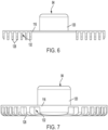
FIG. 6 is a front view of the blade guard ofFIG. 4 . -
FIG. 7 is a side view of the blade guard ofFIG. 4 . -
FIG. 8 is a bottom view of the blade guard ofFIG. 4 . -
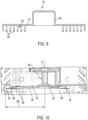
FIG. 9 is a section view taken from line 9-9 ofFIG. 8 . -
FIG. 10 is the section view ofFIG. 9 with a cutting blade installed thereon. -
FIG. 11 is a bottom view of the garden tool ofFIG. 1 . -
FIG. 12 is a perspective view of the forward bumper of the garden tool ofFIG. 1 . -
FIG. 13 is a perspective view of the rearward bumper of the garden tool ofFIG. 1 . -
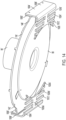
FIG. 14 is a bottom perspective view of another embodiment of a blade guard with a blade mounted thereto. -
FIG. 15 is a bottom perspective view of another embodiment of a blade guard mounted to a garden tool. - Before any embodiments of the invention are explained in detail, it is to be understood that the invention is not limited in its application to the details of construction and the arrangement of components set forth in the following description or illustrated in the following drawings. The invention is capable of other embodiments and of being practiced or of being carried out in various ways. Also, it is to be understood that the phraseology and terminology used herein is for the purpose of description and should not be regarded as limiting.
-
Figures 1-3 illustrate arobotic garden tool 10. More specifically, thegarden tool 10 is a robotic lawn mower for use to cut vegetation such as grass in an enclosedcutting area 14. Thecutting area 14 generally includes, but is not limited to, a continuous area of grass or other vegetation that is enclosed by one ormore barriers 16. In the illustrated embodiment, thebarriers 16 include a series of electrified wires enclosing thecutting area 14 while in alternative embodiments different form of barrier may be used such as, but not limited to, walls, pavers, virtual barriers created by GPS data points or beacons, and the like. As shown inFIG. 1 ,such barriers 16 may be used to enclose theoverall cutting area 14 and/or to segregate one or more interior regions from thecutting area 14. While the illustratedgarden tool 10 is a lawn mower, it is understood that in alternative embodiments thegarden tool 10 may include, but is not limited to, a robotic trimmer, and the like. - As shown in
FIGS. 2 and 3 , thetool 10 is an electrically powered, self-propelled device that includes abody 18, a plurality ofwheels 22 rotatably mounted to thebody 18, acutting assembly 26 mounted to thebody 18, acontroller 30, and abattery 32. Thebody 18, in turn, includes a front orfirst end 34, rear orsecond end 38 opposite thefirst end 34, a right orfirst side 42, and a left orsecond side 46 opposite thefirst side 42. Thebody 18 also defines alongitudinal axis 50 extending along the length of thebody 18 and centered between thefirst side 42 and the second side 46 (e.g., passing through both the first andsecond ends 34, 38). Thebody 18 also defines alateral axis 54 extending along the width of thebody 18 and centered between the first andsecond ends 34, 38 (e.g., passing through both the first andsecond sides 42, 46). Thebody 18 also defines a central axis 58 generally positioned at the intersection of the longitudinal andlateral axes - As shown in
FIG. 3 , thetool 10 includes fourwheels body 18 and configured to support thetool 10 for self-driven movement along a support surface 60 (e.g., the surface of the cutting area 14). In the illustrated embodiment, thewheels undriven wheels wheels wheels 22 may be driven and all or any sub-set of thewheels 22 may be steerable. Furthermore, while the illustrated steerable wheels are passive in nature (e.g., a caster-style wheel), it is understood that in alternative embodiments thesteerable wheels controller 30. In still other embodiments, thetool 10 may include more orfewer wheels 22 positioned in different arrangements about thetool 10. In still other embodiments, thewheels 22 may be replaced by other forms of propulsion such as, but not limited to, tracks, omni-wheels, walking legs, and the like. - The driven
wheels tool 10 are positioned proximate thesecond end 38 of thebody 18 and rotate about a commonrear axis 64 oriented perpendicular to thelongitudinal axis 50. In the illustrated embodiment, eachrear wheel electric motor tool 10 over the support surface 60. In some embodiments, thewheels 22 may be mounted directly to arespective motor - During use, the
controller 30 is configured to output signals to thewheel motors motor wheels controller 30 is configured to output signals to eachmotor wheel controller 30 may instruct amotor respective wheel first end 34 of the body 18) or a rearward direction opposite the forward direction (e.g., rotating therespective wheel second end 38 of the body 18). - In the illustrated embodiment, the driven
wheels wheels -
FIG. 2 illustrates the cuttingassembly 26 of thetool 10. More specifically, the cuttingassembly 26 includes ablade guard 84 defining aguard axis 76, a cuttingmotor 72 mounted to theblade guard 84, and acutting blade 80 in operable communication with the cuttingmotor 72 and configured to rotate with respect to theblade guard 84 about ablade axis 74. As shown inFIG. 3 , the illustratedblade axis 74 is coincident with theguard axis 76. However, in alternative embodiments, theblade axis 74 may be set at an angle to theguard axis 76 and/or offset from theguard axis 76. - In the illustrated embodiment, cutting
assembly 26 is a "floating" assembly such that its position can be adjusted relative to thebody 18 during operation. More specifically, theblade guard 80 acts as a mounting point for themotor 72 and/orblade 80 so that all three elements move together as a unit during use relative to thebody 18 while maintaining their relative alignment. In the illustrated embodiment, the cuttingassembly 26 may be adjusted vertically (e.g., axially along the central axis 58) relative to thebody 18 to allow the cutting height (e.g., the distance between theblade 80 and the support surface 60) to be adjusted. In still other embodiments, the cuttingassembly 26 may also pivot or rotate relative to thebody 18 to allow the cuttingassembly 26 to accommodate variations in the contour of the support surface 60 and the like. - As shown in
FIG. 2 , themotor 72 of the cuttingassembly 26 is mounted to theblade guard 84 and configured to drive theblade 80 relative thereto. During use, themotor 72 is configured to receive signals from thecontroller 30 indicating the speed and direction of rotation of theblade 80 relative to theguard 84. - As shown in
FIG. 10 , thecutting blade 80 of the cuttingassembly 26 includes one ormore blade elements 94 and is configured to rotate about theblade axis 74 during use. In the illustrated embodiment, theblade 80 includes aspindle 100 configured to be coupled to themotor 72, and one ormore arms 104 extending radially outwardly from thespindle 100 opposite themotor 72 to form a correspondingdistal end 108 to which theblade elements 94 are removably attached thereto. While the illustrated cuttingassembly 26 includes threearms 104 each extending radially outwardly from thespindle 100 at equal intervals from each other (e.g., every 121.66 degrees), in other embodiment, more orfewer arms 104 and/orblade elements 94 may be present. Furthermore, while the illustratedcutting blade 80 is shown being attached directly to themotor 72, it is understood that in alternative embodiments themotor 72 may drive theblade 80 indirectly via a series of gears. In such embodiments, thecutting blade 80 andmotor 72 may rotate about different axes. - In still other embodiments, the
arms 104 of thecutting blade 80 may be replaced by other structures configured to position theblade elements 94 at the desired radial distance from theguard axis 76. For example, thecutting blade 80 may include a disk withblade elements 94 coupled to the periphery thereof, radial and circumferential struts forming a structure to which theblade elements 94 may be coupled, and the like. In still other embodiments, theblade elements 94 may be formed integrally with the body of thecutting blade 80 to form a single unit. - In the illustrated embodiment, the
cutting blade 80 defines ablade diameter 208 generally defined as twice the distance between theblade axis 74 and the most radially distant point of thelongest arm 104. In the illustrated embodiment, thecutting blade 80 may include ablade diameter 208 that is no less than 90% thebody width 204 at that same location (e.g., the distance between thefirst end 42 and thesecond end 46 measured parallel to the lateral axis 54). In other embodiments, theblade diameter 208 is no less than 85%, 80%, 75%, and 70% of thebody width 204 at that same location. In still other embodiments, thedistal end 108 of thelongest arm 104 will be positioned no further than 10cm from thecorresponding side distal end 108 of thelongest arm 104 will be positioned no less than 8cm, 6cm, and 5cm from thecorresponding side distal end 108 is at its closest proximity thereto. - As shown in
FIGS. 4-9 , theblade guard 84 is configured to at least partially encompass and protect thecutting blade 80 while allowing grass and vegetation access thereto while thetool 10 travels in the forward F1 and rearward F2 directions. More specifically, theblade guard 84 serves multiple roles during use including allowing theblade 80 to freely rotate about theguard axis 76, allowing grass and other vegetation to come into contact with theblade 80 regardless of whether thetool 10 is traveling in the forward F1 or rearward F2 direction, protecting thecutting blade 80 from the ground and large debris, and protecting the end user from coming into contact with theblade 80 while theblade 80 is rotating. - The
blade guard 84 includes abody 112 having abase plate 116 defining theguard axis 76, ahub 120 extending axially from one side of thebase plate 116 to form a first orclosed end 124, and a plurality ofribs 128 extending from thebase plate 116 opposite thehub 120. Together, theribs 128,base plate 116, andhub 120 at least partially enclose ablade volume 132 configured to at least encompass thecutting blade 80 therein. Theblade guard 84 also defines a longitudinal axis 126 and a lateral axis 130, each passing through theguard axis 76. When theblade guard 84 is installed on thebody 18, the longitudinal axis 126 generally aligns with thelongitudinal axis 50 of thebody 18 while the lateral axis 130 generally corresponds to thelateral axis 54 of thebody 18. - As shown in
FIG. 8 , thebase plate 116 of theblade guard 84 is a flat plate having a leading edge 134, a trailing edge 138 opposite the leading edge 134, a left orfirst side 142 extending between the leading edge 134 and the trailing edge 138, and a right orsecond side 146 extending between the leading edge 134 and the trailing edge 138 and opposite the firstarcuate side 142. When theguard 84 is installed on thebody 18, the leading edge 134 is positioned proximate thefirst end 34 of thebody 18, the trailing edge 138 is positioned proximate thesecond end 38 of thebody 18, thefirst side 142 is positioned proximate thefirst edge 42, and thesecond side 146 is positioned proximate thesecond edge 46. In the illustrated embodiment, the leading and trailing edges 134, 138 are generally linear in contour while the first andsecond sides base plate 116 may form different shapes whereby theedges base plate 116 may include a rectangular shape, a circular shape, and/or other polygonal shapes. In still other embodiments, thebase plate 116 may form some combination thereof. - The
hub 120 of theblade guard 84 is substantially cylindrical in shape extending axially from thebase plate 116 from one side thereof to form anenclosed end 144. During use, theenclosed end 144 of thehub 120 is mounted to thebody 18 of the tool 10 (e.g., via a height adjuster or other adjustment mechanism). - The
blade guard 84 also includes a plurality ofribs 128 extending from thebase plate 116 and configured to at least partially define theblade volume 132 therebetween. Eachrib 128 is substantially "C" shaped having afirst end 140 extending axially away from thebase plate 116, asecond end 144 opposite thefirst end 140 also extending axially away from thebase plate 116, and anintermediate portion 148 extending therebetween and spaced a distance from the base plate 116 (seeFIG. 5 ). In the illustrated embodiment, eachrib 128 is substantially parallel to bothadjacent ribs 128 to form a plurality of gaps 152 therebetween. As shown inFig. 8 , eachrib 128 is oriented parallel to the longitudinal axis 126 of theblade guard 84. When installed, eachrib 128 is also parallel to thelongitudinal axis 50 of thebody 18 and is parallel to both the forward F1 and rearward F2 directions of travel. - Together, the
ribs 128 and thebase plate 116 encompass thecutting blade 80 both radially and axially. More specifically, theblade guard 84 is positioned so that a datum axis oriented perpendicular to theguard axis 76 will have theguard 84 positioned immediately outside both sides of the blade 80 (e.g., radially encompassed; rib, blade, rib). Furthermore, a datum axis oriented parallel to theguard axis 76 will have theguard 84 positioned immediately above and below the blade 80 (e.g., axially encompassed; plate, blade, rib). Stated differently, theblade guard 84 is shaped so that at least a portion of theblade guard 84 axially overlaps thecutting blade 80. Furthermore, theblade guard 84 is shaped so that at least a portion of theblade guard 84 is positioned below the cutting blade 80 (e.g., positioned between the cuttingblade 80 and the support surface 60). - As shown in
FIGS. 6 and8 , each gap 152 of theblade guard 84 is oriented parallel to the longitudinal axis 126 of theblade guard 84 and extends the entire longitudinal length of theblade guard 84, being open on both ends. When theguard 84 is installed on thebody 18, each gap 152 is parallel to thelongitudinal axis 50 of thebody 18 and is parallel to both the forward F1 and rearward F2 directions of travel. By doing so, the gaps 152 allow vegetation or grass to enter each gap 152, travel along the longitudinal length of each gap 152, and exit each gap 152 with the tops of the vegetation passing through the gaps 152 and extending into theblade volume 132 regardless of whether thetool 10 is traveling in the forward F1 or rearward F2 direction. As the gaps 152 are unimpeded along their entire longitudinal length, the vegetation remains upright as it is engaged and cut by theblade 80 making for a more even cut. [[ADD axis test]] - In the illustrated embodiment, the
ribs 128 are formed into two groups, each positioned proximate the sides of theblade guard 84 with a large open region 156 therebetween. More specifically, the open region 156 generally corresponds laterally to the width of the flat portions of thebase plate 116 while theribs 128 are positioned in the regions laterally outside the flats. Together, theribs 128 are positioned so that theguard 84 forms a central "open" portion (e.g., where noribs 128 are positioned below the blade 80), and two "enclosed" portions on either side perpendicular to the direction of travel F1, F2 (e.g., where theribs 128 are positioned below the blade 80). As shown inFig. 8 , theblade guard 84 is symmetric about the lateral axis 130. - As shown in
FIG. 3 , theblade guard 84 is laterally centered with respect to thebody 18 of the tool 10 (e.g., theguard axis 76 is lies on the longitudinal axis 50). However, in alternative embodiments theblade guard 84 may be offset to one side or the other. Furthermore, in the illustrated embodiment, the guard width 200 (e.g., the greatest width of theblade guard 84 measured parallel to thelateral axis 54, seeFIG. 8 ) is equal to thebody width 204 at the same location. However, in alternative embodiments, the guard width 200 may be greater than or equal to 95%, be greater than or equal to 90%, be greater than or equal to 85%, be greater than or equal to 80%, or be greater than or equal to 75% of thebody width 204. - As shown in
FIG. 11 , thebody 18 of thetool 10 also includes a forwardbody grass comb 162a and rearwardbody grass comb 162b. Theforward grass comb 162a is positioned between the cuttingblade 80 and thefirst end 34 while therearward grass comb 162b is positioned between the cuttingblade 80 and thesecond end 38. As such, the twograss combs cutting blade 80. More specifically, the twograss combs cutting blade 80 regardless of whether thetool 10 is traveling in the first direction F1 (e.g., when theforward grass comb 162a is positioned upstream of thecutting blade 80 during operation) or the second direction F2 (e.g., when therearward grass comb 162b is positioned upstream of thecutting blade 80 during operation). While the illustrated embodiment includes twocombs cutting blade 80 in additional directions of travel. - Both
grass combs teeth 166 extending downwardly from the underside of thetool body 18 to form a plurality ofgaps 170 therebetween. Eachtooth 166, in turn, is oriented so that the resultinggaps 170 extend parallel with thelongitudinal axis 50 of thebody 18. Stated differently, thegaps 170 are oriented so that they extend parallel to the direction of travel F1, F2 when thecomb forward grass comb 162a and parallel to the rearward direction F2 for therearward grass comb 162b). -
FIGS. 12 and 13 illustrate a pair ofbumpers body 18 and configured to output a signal to thecontroller 30 upon interacting with an external feature (e.g., a user's hand, a user's foot, a rock, a wall, and the like). More specifically, thebumpers body 18 such that when acorresponding bumper 174a 174b comes into contact with an external feature, thebumper body 18 and subsequently outputs a signal to thecontroller 30 indicating the same. In the illustrated embodiment, thetool 10 includes aforward bumper 174a positioned just forward of thefirst end 34 of thebody 18, and arearward bumper 174b positioned just rearward of thesecond end 38 of thebody 18. Although not shown, additional bumpers may also be present. - Each
bumper outer surface 178 facing away from thebody 18. More specifically, eachbumper planar portion 182 and a plurality ofteeth 186 extending downwardly from theplanar portion 182 toward the support surface 60 to produce a plurality ofgaps 190 therebetween. Together, theteeth 186 andgaps 190 form a bumper comb. During use, theteeth 186 are sized to permit the grass or other vegetation to pass therethrough with minimal resistance while still remaining small enough to restrict access of a user's feet or fingers from gaining access to thecutting blade 80. - As shown in
FIGS. 12 and 13 , eachtooth 186 of theforward bumper 174a and therearward bumper 174b generally curves toward thebody 18 as it extends toward the support surface 60 to generate a tapered shape. This shape helps facilitate slope climbing without undesired contact between the support surface 60 and the bottom end of thebumper 174a. - In the illustrated embodiment, the
tool 10 includes forward andrearward bumper combs cutting blade 80 whether thetool 10 is traveling in the forward direction F1 or the rearward direction F2. As such, thetool 10 is able to operate at maximum efficiency in both directions. - While not shown, it is understood that in alternative embodiments the
tool 10 may only include the bumper combs 174a, 174b, and/or the body combs 162a, 162b in a particular embodiment. In such embodiments, the bumper combs 174a, 174b orbody combs cutting blade 80 and one behind the cutting blade 80) to allow for operation in both the first and second direction F1, F2. - While not shown, various aspects or subcomponents of the
tool 10 may support one or more axes of symmetry to better accommodate vegetation cutting while traveling in both the first and second directions F1, F2. For example, thewheels 22 may be oriented on thetool 10 so that they have at least longitudinal symmetry (e.g., the axis of symmetry is parallel to thelateral axis 54 or front to back symmetry). Furthermore, any sensors mounted to thebody 18 to produce at least longitudinal symmetry. In still other embodiments, the bumpers 174, the grass combs 162, the cuttingassembly 26, and the like may also include at least longitudinal symmetry to better accommodate vegetation cutting while traveling in both the first and second directions F1, F2. In still other embodiments, additional axes of symmetry may be present in the above described sub-components to allow vegetation cutting in still more directions of travel (e.g., side-to-side travel, pivoting about a given axis of rotation, and the like). -
FIG. 14 illustrates another embodiment of the blade guard 84'. The blade guard 84' is substantially similar to theblade guard 84 described above so only the differences will be described in detail herein. The base plate 116' of the blade guard 84' is substantially disk shaped having an outer periphery that is similar to but slightly greater than theblade diameter 208 of thecorresponding cutting blade 80. In instances wheremultiple blades 80 are to be used interchangeably with a single blade guard 84', the periphery of the base plate 116' is similar but slightly greater than theblade diameter 208 of the largest intendedblade 80. - The blade plate 116' also includes a pair of mounting points 1000' extending radially outwardly and axially upwardly (e.g., away from the support surface 60) from the first and second sides 142', 146' thereof. Each mounting point 1000', in turn, provides a mounting location to which a corresponding side guard 1004' may be coupled thereto.
- Each side guard 1004' is coupled to a corresponding mounting point 1000' of the blade plate 116' and configured to restrict horizontal and underneath access to the
cutting blade 80 during use. More specifically, each side guard 1004' is positioned so that it restricts access to thecutting blade 80 at the locations where theblade 80 is positioned closest to the periphery of thetool body 18. In the illustrated embodiment, theblade 80 is closest to the periphery at the twosides cutting blade 80 along any access vectors available to the user's feet, hands, and the like. - Each side guard 1004' includes a first portion 1008' extending axially downwardly from the blade plate 116' relative to the guard axis 76' and a second portion 1012' extending radially inwardly from the first portion 1008' opposite the blade plate 116'. In the illustrated embodiment, the first portion 1008' of each side guard 1004' is solid, having no apertures or access points formed therein while the second portion 1012' forms a grate of alternating slots 1016' and beams 1020'.
- As shown in
FIG. 14 , the slots 1016' and beams 1020' of the second portion 1012' of the side guard 1004' are oriented so that they are parallel to thelongitudinal axis 50 when the guard 84' is mounted to thetool body 18. This orientation serves two purposes, the first to not allow any fingers or toes access to theblade 80, and also to assure that grass and other vegetation is able to access theblade 80 when thetool 10 is traveling in both the first F1 and second F2 directions. In the illustrated embodiment, the second portion 1012' includes acentral beam 1020a' extending radially inwardly from the first portion 1008', and a plurality oflateral beams 1020b' extending perpendicular to thecentral beam 1020a' at pre-determined intervals to define a corresponding slot 1016' having a slot width 1024' therebetween. As shown inFIG. 14 , thelateral beams 1020b' extend outwardly from thecentral beam 1020a' in both a forward and rearward direction (e.g., parallel to the longitudinal axis 50) such that the resulting slots 1016' are open toward both thefirst end 34 and thesecond end 38 of the tool 10 (e.g., toward both the first F1 and second F2 direction of travel). Each side guard 1004' also includes anarcuate beam 1020c' positioned at the radially inward-most position of thecentral beam 1020a' and curved to be such that the resulting curve is co-axial with the guard axis 76'. - In the illustrated embodiment, each slot width 1024' is no greater than 12mm, 10mm, 8mm, 6mm, and 4mm. In other embodiments, each slot 1016' is sized so that it will not permit a 12mm diameter cylinder to pass therethrough.
- While the illustrated side guards 1004' are shown being formed separately and fastened to the blade plate 116' using one or more fasteners, it is understood that in alternative embodiments the side guards 1004' may be formed integrally with the blade plate 116'. In still other embodiments, the side guards 1004' may be fastened to the blade plate 116' so that the axial height between the second portion 1012' and the blade plate 116' may be adjustable.
-
FIG. 15 illustrates another embodiment ofblade guard 84". Theblade guard 84" is substantially similar to the blade guard 84' described above so only the differences will be discussed in detail here. Theblade plate 116" of theblade guard 84" includes a first orgrass comb 2000" integrally formed with theblade plate 116" and positioned between theguard axis 76" and thefront end 34 of thetool body 18, and a second orrear grass comb 2004" integrally formed with theblade plate 116" and positioned between theguard axis 76" and therear end 38 of thetool body 18. By being integrally formed with theblade plate 116", both the first and second grass combs 2000", 2004" float together with the rest of the cuttingassembly 26. This allows the grass combs 2000", 2004" are able to travel along and conform to the contour of the support surface 60. - As shown in
FIG. 15 , both the first andsecond combs 2000", 2004" define acomb width 2008" measured parallel to thelateral axis 54. In the illustrated embodiment, bothcombs 2000", 2004" have acomb width 2008" that is greater than theblade diameter 208 of theblade 80. Thecombs 2000", 2004" are also both shaped so that the depth of theindividual teeth 166" within eachcomb 2000", 2004" decreases the further acorresponding tooth 166" is positioned from the lateral center of the tool 10 (e.g., the further from the longitudinal axis 50). While bothcombs 2000", 2004" have substantially thesame comb width 2008" and comb contour, it is understood that in alternative embodiments eachcomb 2000", 2004" may have aunique width 2008" and contour. - The
blade guard 84" is shaped so that it has at least one axis of symmetry therethrough. More specifically, the illustrated blade guard has two axes of symmetry - a first axis of symmetry in the longitudinal direction (e.g., with the axis of symmetry parallel to thelateral axis 54 or front/back symmetric), and a second axis of symmetry in the lateral direction (e.g., with the axis of symmetry parallel to thelongitudinal axis 50 or side to side symmetric). The symmetric nature of theblade guard 84" better facilitates the ability of thetool 10 to operate (e.g., cut vegetation) while traveling in both the first direction F1 and the second direction F2. In instances where more traveling directions are to be accommodated, more axis of symmetry may be present in theblade guard 84".
Claims (20)
- A robotic garden tool comprising:a body having a first end and a second end opposite the first end;one or more wheels rotatably coupled to the body;a cutting assembly coupled to the body;a first grass comb positioned between the cutting assembly and the first end; anda second grass comb positioned between the cutting assembly and the second end.
- The robotic garden tool of claim 1, further comprising a first bumper movably coupled to the body proximate the first end, and wherein the first bumper includes a first bumper comb.
- The robotic garden tool of claim 2, further comprising a second bumper movably coupled to the body proximate the second end, and wherein the second bumper includes a second bumper comb.
- The robotic garden tool of claim 1, wherein the cutting assembly includes a blade guard defining a guard axis, a motor fixedly coupled to the blade guard, and a cutting blade rotatable with respect to the blade guard about the guard axis.
- The robotic garden tool of claim 4, wherein the body defines a longitudinal axis passing through the first end and the second end, and wherein the blade guard includes a plurality of ribs, and wherein each rib is oriented parallel to the longitudinal axis.
- The robotic garden tool of claim 4, wherein the blade guard includes a base plate and one or more ribs, wherein at least a portion of at least one rib is spaced a distance from the base plate to define a volume therebetween, and wherein at least a portion of the cutting blade is positioned within the volume when rotating with respect to the blade guard about the guard axis.
- The robotic garden tool of claim 4, wherein the body defines a longitudinal axis passing through the first end and the second end, wherein at least one of the first grass comb and the second grass comb define a comb width measured perpendicular to the longitudinal axis, and wherein the comb width is greater than the blade diameter.
- The robotic garden tool of claim 1, wherein the body defines a longitudinal axis passing through the first end and the second end, wherein at least one of the first grass comb and the second grass comb include a plurality of teeth forming gaps therebetween, and where at least one gap is shaped so that a datum axis oriented parallel to the longitudinal axis can pass through a given gap without engaging either of the teeth adjacent the gap.
- The robotic garden tool of claim 1, wherein the body defines a longitudinal axis passing through the first end and the second end, wherein at least one of the first grass comb and the second grass comb include a plurality of teeth forming gaps therebetween, and wherein each gap is parallel to the longitudinal axis.
- The robotic garden tool of claim 1, wherein at least one of the first grass comb and the second grass comb is movably coupled to the body.
- The robotic garden tool of claim 1, wherein at least one of the first grass comb and the second grass comb is fixedly coupled to the body.
- A robotic garden tool comprising:a body having a first end and a second end opposite the first end, wherein the body defines a longitudinal axis passing through both the first end and the second end; anda cutting assembly coupled to the body, wherein the cutting assembly includes:a blade guard defining an axis of rotation, the blade guard including a base plate and one or more ribs, wherein at least a portion of at least one rib is spaced from the base plate to define a volume therebetween,a cutting blade rotatable with respect to the blade guard about the axis of rotation, and wherein the at least a portion of the cutting blade is positioned within the volume.
- The robotic garden tool of claim 12, one or more grass combs coupled to the body between the cutting assembly and one of the first end and the second end.
- The robotic garden tool of claim 12, wherein the cutting assembly further comprises a motor fixedly coupled to the blade guard and configured to rotate the cutting blade with respect to the blade guard about the axis of rotation.
- The robotic garden tool of claim 12, wherein the blade guard defines a longitudinal blade guard axis, and wherein the one or more ribs are parallel to the blade guard axis.
- The robotic garden tool of claim 15, wherein the longitudinal blade guard axis is parallel to the longitudinal axis of the body when the blade guard is in a rest position.
- The robotic garden tool of claim 12, wherein the blade guard includes one or more side guards, and wherein the side guards form the one or more ribs.
- The robotic garden tool of claim 17, wherein the side guards are removably coupled to the base plate.
- The robotic garden tool of claim 17, wherein each side guard includes a first portion extending perpendicular to the base plate and a second portion extending perpendicular to the first portion, and wherein the second portion forms the one or more ribs.
- The robotic garden tool of claim 12, wherein the blade guard includes a lateral axis oriented perpendicular to the longitudinal axis of the body, and wherein the blade guard is symmetric about the lateral axis.
Applications Claiming Priority (1)
| Application Number | Priority Date | Filing Date | Title |
|---|---|---|---|
| US202263321487P | 2022-03-18 | 2022-03-18 |
Publications (2)
| Publication Number | Publication Date |
|---|---|
| EP4265096A1 true EP4265096A1 (en) | 2023-10-25 |
| EP4265096B1 EP4265096B1 (en) | 2026-08-19 |
Family
ID=85703904
Family Applications (1)
| Application Number | Title | Priority Date | Filing Date |
|---|---|---|---|
| EP23162511.2A Active EP4265096B1 (en) | 2022-03-18 | 2023-03-17 | Robotic garden tool |
Country Status (4)
| Country | Link |
|---|---|
| US (1) | US20230292661A1 (en) |
| EP (1) | EP4265096B1 (en) |
| CN (2) | CN116762550A (en) |
| AU (1) | AU2023201661A1 (en) |
Families Citing this family (2)
| Publication number | Priority date | Publication date | Assignee | Title |
|---|---|---|---|---|
| CN118749295B (en) * | 2024-07-04 | 2025-01-24 | 广东土人园林建设有限公司 | An intelligent device for mowing garden grass to avoid dust |
| CN223349109U (en) * | 2024-10-30 | 2025-09-19 | 深圳库犸科技有限公司 | From mobile devices |
Citations (5)
| Publication number | Priority date | Publication date | Assignee | Title |
|---|---|---|---|---|
| CN204653018U (en) * | 2015-01-15 | 2015-09-23 | 杭州菲沃机器人科技有限公司 | For the cutter-head mechanism of hand-push type mower |
| WO2015184674A1 (en) * | 2014-06-06 | 2015-12-10 | 嘉兴亚特园林机械研究所 | Lawnmower protective device and lawnmower |
| CN106561148A (en) * | 2015-10-13 | 2017-04-19 | 苏州宝时得电动工具有限公司 | Lawn mower |
| WO2020253794A1 (en) * | 2019-06-18 | 2020-12-24 | 苏州宝时得电动工具有限公司 | Automatic lawn mower |
| EP3949713A1 (en) * | 2019-03-28 | 2022-02-09 | Positec Technology (China) Co., Ltd (Non-Small Entity) | Protection member, blade assembly, and mower |
Family Cites Families (11)
| Publication number | Priority date | Publication date | Assignee | Title |
|---|---|---|---|---|
| FR2682259A1 (en) * | 1991-10-14 | 1993-04-16 | Roussillon Patrick | Comb for a scrub clearing machine |
| JP3737674B2 (en) * | 2000-05-24 | 2006-01-18 | 株式会社共立 | Cutting blade safety cover for brush cutter |
| US8306659B2 (en) * | 2006-12-06 | 2012-11-06 | F Robotics Acquisitions Ltd. | Autonomous robot |
| US10149430B2 (en) * | 2013-02-20 | 2018-12-11 | Husqvarna Ab | Robotic work tool configured for improved turning in a slope, a robotic work tool system, and a method for use in the robot work tool |
| JP2016208950A (en) * | 2015-05-13 | 2016-12-15 | シャープ株式会社 | Guard mechanism and lawn mower |
| US10293855B2 (en) * | 2016-07-13 | 2019-05-21 | Harry Swecker | Zero-turn mower with selective steering control |
| US9807930B1 (en) * | 2016-08-25 | 2017-11-07 | Irobot Corporation | Blade guard for a robot lawnmower |
| DE102017203094A1 (en) * | 2017-02-24 | 2018-08-30 | Robert Bosch Gmbh | Method for protecting a body part |
| CN209105654U (en) * | 2018-11-16 | 2019-07-16 | 苏州科瓴精密机械科技有限公司 | Grass-removing robot |
| SE544545C2 (en) * | 2019-09-25 | 2022-07-12 | Husqvarna Ab | Propulsion control arrangement, robotic tool, method of propelling robotic tool and related devices |
| CN213044199U (en) * | 2020-02-28 | 2021-04-27 | 上海山科机器人有限公司 | Lawn mower |
-
2023
- 2023-03-16 US US18/185,244 patent/US20230292661A1/en active Pending
- 2023-03-16 AU AU2023201661A patent/AU2023201661A1/en active Pending
- 2023-03-17 EP EP23162511.2A patent/EP4265096B1/en active Active
- 2023-03-20 CN CN202310281170.0A patent/CN116762550A/en active Pending
- 2023-03-20 CN CN202310275019.6A patent/CN116762555A/en active Pending
Patent Citations (5)
| Publication number | Priority date | Publication date | Assignee | Title |
|---|---|---|---|---|
| WO2015184674A1 (en) * | 2014-06-06 | 2015-12-10 | 嘉兴亚特园林机械研究所 | Lawnmower protective device and lawnmower |
| CN204653018U (en) * | 2015-01-15 | 2015-09-23 | 杭州菲沃机器人科技有限公司 | For the cutter-head mechanism of hand-push type mower |
| CN106561148A (en) * | 2015-10-13 | 2017-04-19 | 苏州宝时得电动工具有限公司 | Lawn mower |
| EP3949713A1 (en) * | 2019-03-28 | 2022-02-09 | Positec Technology (China) Co., Ltd (Non-Small Entity) | Protection member, blade assembly, and mower |
| WO2020253794A1 (en) * | 2019-06-18 | 2020-12-24 | 苏州宝时得电动工具有限公司 | Automatic lawn mower |
Also Published As
| Publication number | Publication date |
|---|---|
| CN116762550A (en) | 2023-09-19 |
| EP4265096B1 (en) | 2026-08-19 |
| US20230292661A1 (en) | 2023-09-21 |
| CN116762555A (en) | 2023-09-19 |
| AU2023201661A1 (en) | 2023-10-05 |
Similar Documents
| Publication | Publication Date | Title |
|---|---|---|
| CN108323310B (en) | Mowing Robot | |
| US20230292661A1 (en) | Multi-directional blade guard | |
| US11464164B2 (en) | High-efficiency cutting system | |
| CN108323309B (en) | Mowing Robot | |
| EP3075222B1 (en) | Lawn mower with blade disc | |
| JP7108461B2 (en) | lawn mower | |
| EP3772891B1 (en) | Lawnmower cutting deck, lawnmower, and method of mowing a lawn | |
| JP2016208950A (en) | Guard mechanism and lawn mower | |
| BR102013014306B1 (en) | GRASS CUTTING BLADE FOR A MOWER | |
| US6374584B1 (en) | Reel type laser lawn mower | |
| US20230292656A1 (en) | Robotic garden tool and method | |
| US3780504A (en) | Lawn mower | |
| JP2009118823A (en) | Lawn mower | |
| CN111436274A (en) | Protection mechanism of cutting mechanism, combination of cutting mechanism and protection mechanism | |
| JP7611697B2 (en) | Electric disc grass cutter | |
| WO2016121167A1 (en) | Guide mechanism, mowing mechanism, autonomous traveling vehicle, and autonomous traveling vehicle system | |
| US20230263095A1 (en) | Garden tool with blade cover | |
| WO2005077144A1 (en) | A knife protect cover of weed cuter | |
| US20230339348A1 (en) | Robotic tool and charging station | |
| US20220161368A1 (en) | Vegetation edger with laser and method | |
| EP4487670A1 (en) | A robotic lawn mower with enhanced cutting properties | |
| US20190069481A1 (en) | Attachment plate for supporting walk behind trimmers with third wheel | |
| JP2015107083A (en) | Mower | |
| RU2773946C2 (en) | Electric drive disc mower | |
| JPH10150824A (en) | Walking mower |
Legal Events
| Date | Code | Title | Description |
|---|---|---|---|
| PUAI | Public reference made under article 153(3) epc to a published international application that has entered the european phase |
Free format text: ORIGINAL CODE: 0009012 |
|
| STAA | Information on the status of an ep patent application or granted ep patent |
Free format text: STATUS: THE APPLICATION HAS BEEN PUBLISHED |
|
| AK | Designated contracting states |
Kind code of ref document: A1 Designated state(s): AL AT BE BG CH CY CZ DE DK EE ES FI FR GB GR HR HU IE IS IT LI LT LU LV MC ME MK MT NL NO PL PT RO RS SE SI SK SM TR |
|
| STAA | Information on the status of an ep patent application or granted ep patent |
Free format text: STATUS: REQUEST FOR EXAMINATION WAS MADE |
|
| 17P | Request for examination filed |
Effective date: 20240410 |
|
| RBV | Designated contracting states (corrected) |
Designated state(s): AL AT BE BG CH CY CZ DE DK EE ES FI FR GB GR HR HU IE IS IT LI LT LU LV MC ME MK MT NL NO PL PT RO RS SE SI SK SM TR |
|
| GRAP | Despatch of communication of intention to grant a patent |
Free format text: ORIGINAL CODE: EPIDOSNIGR1 |
|
| STAA | Information on the status of an ep patent application or granted ep patent |
Free format text: STATUS: GRANT OF PATENT IS INTENDED |
|
| INTG | Intention to grant announced |
Effective date: 20260311 |
|
| GRAS | Grant fee paid |
Free format text: ORIGINAL CODE: EPIDOSNIGR3 |
|
| GRAA | (expected) grant |
Free format text: ORIGINAL CODE: 0009210 |
|
| STAA | Information on the status of an ep patent application or granted ep patent |
Free format text: STATUS: THE PATENT HAS BEEN GRANTED |