EP4264070B1 - Foil bearing assembly including segmented inner foils assembly and compressor including this bearing assembly - Google Patents
Foil bearing assembly including segmented inner foils assembly and compressor including this bearing assembly Download PDFInfo
- Publication number
- EP4264070B1 EP4264070B1 EP22704163.9A EP22704163A EP4264070B1 EP 4264070 B1 EP4264070 B1 EP 4264070B1 EP 22704163 A EP22704163 A EP 22704163A EP 4264070 B1 EP4264070 B1 EP 4264070B1
- Authority
- EP
- European Patent Office
- Prior art keywords
- foil
- bearing
- assembly
- tab
- pad
- Prior art date
- Legal status (The legal status is an assumption and is not a legal conclusion. Google has not performed a legal analysis and makes no representation as to the accuracy of the status listed.)
- Active
Links
Images







Classifications
-
- F—MECHANICAL ENGINEERING; LIGHTING; HEATING; WEAPONS; BLASTING
- F16—ENGINEERING ELEMENTS AND UNITS; GENERAL MEASURES FOR PRODUCING AND MAINTAINING EFFECTIVE FUNCTIONING OF MACHINES OR INSTALLATIONS; THERMAL INSULATION IN GENERAL
- F16C—SHAFTS; FLEXIBLE SHAFTS; ELEMENTS OR CRANKSHAFT MECHANISMS; ROTARY BODIES OTHER THAN GEARING ELEMENTS; BEARINGS
- F16C17/00—Sliding-contact bearings for exclusively rotary movement
- F16C17/02—Sliding-contact bearings for exclusively rotary movement for radial load only
- F16C17/024—Sliding-contact bearings for exclusively rotary movement for radial load only with flexible leaves to create hydrodynamic wedge, e.g. radial foil bearings
-
- F—MECHANICAL ENGINEERING; LIGHTING; HEATING; WEAPONS; BLASTING
- F04—POSITIVE - DISPLACEMENT MACHINES FOR LIQUIDS; PUMPS FOR LIQUIDS OR ELASTIC FLUIDS
- F04D—NON-POSITIVE-DISPLACEMENT PUMPS
- F04D29/00—Details, component parts, or accessories
- F04D29/05—Shafts or bearings, or assemblies thereof, specially adapted for elastic fluid pumps
- F04D29/056—Bearings
- F04D29/057—Bearings hydrostatic; hydrodynamic
-
- F—MECHANICAL ENGINEERING; LIGHTING; HEATING; WEAPONS; BLASTING
- F16—ENGINEERING ELEMENTS AND UNITS; GENERAL MEASURES FOR PRODUCING AND MAINTAINING EFFECTIVE FUNCTIONING OF MACHINES OR INSTALLATIONS; THERMAL INSULATION IN GENERAL
- F16C—SHAFTS; FLEXIBLE SHAFTS; ELEMENTS OR CRANKSHAFT MECHANISMS; ROTARY BODIES OTHER THAN GEARING ELEMENTS; BEARINGS
- F16C43/00—Assembling bearings
- F16C43/02—Assembling sliding-contact bearings
-
- F—MECHANICAL ENGINEERING; LIGHTING; HEATING; WEAPONS; BLASTING
- F16—ENGINEERING ELEMENTS AND UNITS; GENERAL MEASURES FOR PRODUCING AND MAINTAINING EFFECTIVE FUNCTIONING OF MACHINES OR INSTALLATIONS; THERMAL INSULATION IN GENERAL
- F16C—SHAFTS; FLEXIBLE SHAFTS; ELEMENTS OR CRANKSHAFT MECHANISMS; ROTARY BODIES OTHER THAN GEARING ELEMENTS; BEARINGS
- F16C2226/00—Joining parts; Fastening; Assembling or mounting parts
- F16C2226/30—Material joints
- F16C2226/36—Material joints by welding
-
- F—MECHANICAL ENGINEERING; LIGHTING; HEATING; WEAPONS; BLASTING
- F16—ENGINEERING ELEMENTS AND UNITS; GENERAL MEASURES FOR PRODUCING AND MAINTAINING EFFECTIVE FUNCTIONING OF MACHINES OR INSTALLATIONS; THERMAL INSULATION IN GENERAL
- F16C—SHAFTS; FLEXIBLE SHAFTS; ELEMENTS OR CRANKSHAFT MECHANISMS; ROTARY BODIES OTHER THAN GEARING ELEMENTS; BEARINGS
- F16C2226/00—Joining parts; Fastening; Assembling or mounting parts
- F16C2226/50—Positive connections
- F16C2226/70—Positive connections with complementary interlocking parts
- F16C2226/76—Positive connections with complementary interlocking parts with tongue and groove or key and slot
-
- F—MECHANICAL ENGINEERING; LIGHTING; HEATING; WEAPONS; BLASTING
- F16—ENGINEERING ELEMENTS AND UNITS; GENERAL MEASURES FOR PRODUCING AND MAINTAINING EFFECTIVE FUNCTIONING OF MACHINES OR INSTALLATIONS; THERMAL INSULATION IN GENERAL
- F16C—SHAFTS; FLEXIBLE SHAFTS; ELEMENTS OR CRANKSHAFT MECHANISMS; ROTARY BODIES OTHER THAN GEARING ELEMENTS; BEARINGS
- F16C2360/00—Engines or pumps
- F16C2360/44—Centrifugal pumps
-
- F—MECHANICAL ENGINEERING; LIGHTING; HEATING; WEAPONS; BLASTING
- F16—ENGINEERING ELEMENTS AND UNITS; GENERAL MEASURES FOR PRODUCING AND MAINTAINING EFFECTIVE FUNCTIONING OF MACHINES OR INSTALLATIONS; THERMAL INSULATION IN GENERAL
- F16C—SHAFTS; FLEXIBLE SHAFTS; ELEMENTS OR CRANKSHAFT MECHANISMS; ROTARY BODIES OTHER THAN GEARING ELEMENTS; BEARINGS
- F16C2362/00—Apparatus for lighting or heating
- F16C2362/52—Compressors of refrigerators, e.g. air-conditioners
Definitions
- the field of the disclosure relates generally to bearing systems, and more particularly, to gas foil bearing assemblies for use in compressors.
- Some refrigerants used in modern refrigeration and cooling systems such as R134a or other low global warming potential (GWP) refrigerants, have a relatively low density which requires higher volume flow compressors such as centrifugal compressors.
- GWP global warming potential
- Centrifugal compressors typically include compressor bearings to support a driveshaft used to transfer power from the motor to the impeller that imparts kinetic energy to incoming refrigerant.
- the compressor bearings are typically provided with one or more features to reduce friction between the compressor bearing and the driveshaft. The design of these friction-reducing features of the bearings pose an on-going challenge due at least in part to the refrigerant and the challenging operating environment within gas compressors such as air conditioning compressors.
- compressor bearings in existing refrigerant compressors use oil or alternative compositions as a lubricant, but some refrigerants are incompatible with at least some existing lubricant compositions.
- Other compressor bearings are oil-free magnetic bearings that levitate the driveshaft within a magnetic field provided by high-strength magnets, but magnetic bearings are typically complex in design, add significant weight, require complicated control, and limit the choice of driveshaft materials to ferromagnetic materials in order to respond to the magnetic fields within the magnetic bearings.
- Another type of oil-free bearings is a foil bearing that includes compliant foil elements that surround the driveshaft and support the driveshaft on a fluid layer formed between the driveshaft and the foil elements when the rotation speed of the driveshaft exceeds a threshold speed termed liftoff speed.
- Foil bearings are well-suited for the high-speed operating environment typical of centrifugal compressors, are compatible with all refrigerant compositions, and may be used with a wider variety of driveshaft materials, thereby permitting the use of lighter-weight materials to reduce the amount of energy needed to operate the compressor.
- At least one consideration when using foil bearing assemblies in centrifugal compressors is sub-synchronous vibrations - i.e., vibrations occurring at a frequency below that of the rotational frequency of the shaft or other rotor supported by the bearings.
- Centrifugal compressors that incorporate foil bearing assemblies can be prone to sub-synchronous vibrations, which can reduce the operating envelope of the compressor.
- a bearing system in one aspect, includes a bearing housing and a foil bearing assembly.
- the bearing housing includes a sleeve that defines a cylindrical bore and includes at least one bearing assembly locking feature, and a mounting structure for connecting the bearing system to a compressor housing.
- the foil bearing assembly is positioned within the cylindrical bore and includes an outer foil assembly, an inner foil assembly, and a bump foil assembly positioned between the outer foil assembly and the inner foil assembly.
- the outer foil assembly includes at least one outer foil pad extending circumferentially from a first end including a bearing retention feature to a second end.
- the bearing retention feature is cooperatively engaged with the at least one bearing assembly locking feature to maintain the foil bearing assembly within the bearing housing at a fixed rotational position.
- the inner foil assembly includes a plurality of inner foil pads spaced circumferentially about the foil bearing assembly. Each inner foil pad extends circumferentially from a tab to a free end. At least one of the inner foil pads is welded to the outer foil assembly along the tab.
- a compressor in another aspect, includes a compressor housing, a driveshaft rotatably supported within the compressor housing, an impeller connected to the driveshaft and operable to impart kinetic energy to incoming refrigerant gas upon rotation of the driveshaft, a bearing housing mounted to the compressor housing, and a foil bearing assembly rotatably supporting the driveshaft.
- the bearing housing includes a sleeve that defines a cylindrical bore and includes at least one bearing assembly locking feature.
- the foil bearing assembly is positioned within the cylindrical bore, and includes an outer foil assembly, an inner foil assembly, and a bump foil assembly positioned between the outer foil assembly and the inner foil assembly.
- the outer foil assembly includes at least one bearing retention feature cooperatively engaged with the at least one bearing assembly locking feature to maintain the foil bearing assembly within the bearing housing at a fixed rotational position.
- the inner foil assembly includes a plurality of inner foil pads spaced circumferentially about the foil bearing assembly. Each inner foil pad extends circumferentially from a tab to a free end. At least one of the inner foil pads is welded to the outer foil assembly along the tab.
- a compressor illustrated in the form of a two-stage refrigerant compressor is indicated generally at 100.
- the compressor 100 generally includes a compressor housing 102 forming at least one sealed cavity within which each stage of refrigerant compression is accomplished.
- the compressor 100 includes a first refrigerant inlet 110 to introduce refrigerant vapor into the first compression stage (not labeled in Fig. 1 ), a first refrigerant exit 114, a refrigerant transfer conduit 112 to transfer compressed refrigerant from the first compression stage to the second compression stage, a second refrigerant inlet 118 to introduce refrigerant vapor into the second compression stage (not labeled in Fig. 1 ), and a second refrigerant exit 120.
- the refrigerant transfer conduit 112 is operatively connected at opposite ends to the first refrigerant exit 114 and the second refrigerant inlet 118, respectively.
- the second refrigerant exit 120 delivers compressed refrigerant from the second compression stage to a cooling system in which compressor 100 is incorporated.
- the refrigerant transfer conduit 112 may further include a refrigerant port 122, for example, for economization.
- the compressor housing 102 encloses a first compression stage 124 and a second compression stage 126 at opposite ends of the compressor 100.
- the first compression stage 124 includes a first impeller 106 configured to add kinetic energy to refrigerant entering via the first refrigerant inlet 110.
- the kinetic energy imparted to the refrigerant by the first impeller 106 is converted to increased refrigerant pressure (i.e. compression) as the refrigerant velocity is slowed upon transfer to a diffuser 136.
- the second compression stage 126 includes a second impeller 116 configured to add kinetic energy to refrigerant transferred from the first compression stage 124 entering via the second refrigerant inlet 118.
- the kinetic energy imparted to the refrigerant by the second impeller 116 is converted to increased refrigerant pressure (i.e. compression) as the refrigerant velocity is slowed upon transfer to a diffuser 138.
- Compressed refrigerant exits the second compression stage 126 via the second refrigerant exit 120 (not shown in Fig. 2 ).
- the first stage impeller 106 and second stage impeller 116 are connected at opposite ends of a driveshaft 104.
- the driveshaft 104 is operatively connected to a motor 108 positioned between the first stage impeller 106 and second stage impeller 116 such that the first stage impeller 106 and second stage impeller 116 are rotated at a rotation speed selected to compress the refrigerant to a pre-selected pressure exiting the second refrigerant exit 120.
- Any suitable motor may be incorporated into the compressor 100 including, but not limited to, an electrical motor.
- the driveshaft 104 is supported by gas foil bearing assemblies 300 positioned within a sleeve 202 of each bearing housing 200/200a, as described in additional detail below.
- Each bearing housing 200/200a includes a mounting structure 210 for connecting the respective bearing housing 200/200a to the compressor housing 102, as illustrated in Fig. 2 .
- each bearing housing 200/200a (only bearing housing 200 illustrated in Fig. 4 ) supports the driveshaft 104, and the driveshaft 104 projects through the bearing housing 200/200a opposite the sleeve 202, and the impeller 106 is connected to the projecting end of the driveshaft 104.
- the gas foil bearing assembly 300 is positioned within a cylindrical bore 206 within the bearing housing 200.
- the driveshaft 104 closely fits within the gas foil bearing assembly 300, which includes an outer compliant foil assembly or foil layer 302 positioned adjacent to the inner wall of the sleeve 202, an inner compliant foil assembly or foil layer 306 (also referred to as a "top foil”) positioned adjacent to the driveshaft 104, and a bump foil assembly or foil layer 310 positioned between the inner foil layer 306 and the outer foil layer 302.
- the foil assemblies or layers 302/306/310 of the gas foil bearing assembly 300 form an essentially cylindrical tube sized to receive the driveshaft 104 with relatively little or no gap design as determined by existing foil bearing design methods.
- the components of the foil bearing assembly 300 may be constructed of any suitable material that enables the foil bearing assembly 300 to function as described herein. Suitable materials include, for example and without limitation, metal alloys.
- each of the outer foil layer 302, the inner foil layer 306, and the bump foil layer 310 is constructed of stainless steel (e.g., 17-4 stainless steel).
- the foil layers can be formed from relatively thin sheets or "foils" of material.
- the foil assemblies or layers 302/306/310 can be constructed of metal sheets having a thickness in the range of 0.003 inches to 0.007 inches.
- the foil bearing assembly 300 in the illustrated embodiment further includes a pair of foil keepers 312a/312b positioned adjacent opposite ends of the layers 302/306/310 to inhibit sliding of the layers 302/306/310 in an axial direction within the cylindrical bore 206 of the sleeve 202.
- Foil retaining clips 314a/314b may be removably connected to bearing housing 200.
- Fig. 8 further illustrates the arrangement of the foil keeper 312a and foil retaining clip 314a at one end of the foil bearing assembly 300.
- each bearing housing 200/200a (only bearing housing 200 illustrated in Fig. 6 ) includes a foil retaining lip 214 formed integrally (e.g., cast) with the bearing housing 200 and projecting radially inward from the radial inner surface 204 that defines the cylindrical bore 206.
- the foil retaining lip 214 is positioned near an impeller end 216 of the cylindrical bore 206 proximal to the impeller 116 (shown in Figs. 2-3 ).
- the foil retaining lip 214 is sized and dimensioned to project a radial distance from the radial inner surface 204 that overlaps at least a portion of the layers 302/306/310 of the foil bearing assembly 300.
- the foil retaining lip 214 may extend fully around the circumference of the radial inner surface 204, or the foil retaining lip can include two or more segments extending over a portion of the circumference of the radial inner surface 204 and separated by spaces flush with the adjacent radial inner surface 204.
- the foil bearing assembly 300 of the embodiment illustrated in Fig. 6 further includes a single foil retaining clip 314 positioned adjacent the ends of the layers 302/306/310 opposite the foil retaining lip 214 to inhibit axial movement of the layers 302/306/310 within the cylindrical bore 206 of the sleeve 202.
- the foil retaining clip 314 snaps into a circumferential groove 212 formed within the radial inner surface 204 of the cylindrical bore 206 near a motor end 218 of the cylindrical bore 206.
- Fig. 9 and Fig. 10 further illustrate the arrangement of the foil retaining clip 314 at one end of the foil bearing assembly 300.
- the foil retaining clip 314 is sized and dimensioned to provide clearance for the outer layer 302, and to overlap with at least one bearing retention feature 304 that forms a radially outward projecting tab 316, as described further below.
- the foil retaining lip 214 may be positioned within any region of the cylindrical bore 206 near the impeller end 216 including, without limitation, a position immediately adjacent to the opening of the cylindrical bore 206 at the impeller end 216.
- the foil retaining lip 214 may be positioned within any region of the cylindrical bore 206 near the motor end 218 including, without limitation, a position immediately adjacent to the opening of the cylindrical bore 206 at the motor end 218.
- the foil retaining clip 314 snaps into a circumferential groove 212 formed within the radial inner surface 204 of the cylindrical bore 206 near the impeller end 216, in an arrangement that is essentially the opposite of the arrangement illustrated in Fig. 6 .
- the foil bearing assembly 300 is installed within the bearing housing 200 by inserting the foil bearing assembly 300 into the cylindrical bore 206 of the bearing housing 200 at the motor end 218. The foil bearing assembly 300 is then advanced axially into the cylindrical bore 206 toward the impeller end 216 until the layers 302/306/310 contact the foil retaining lip 214. The foil retaining clip 314 is then snapped into the circumferential groove 212 near the motor end 218 of the cylindrical bore 206 to lock the foil bearing assembly 300 in place.
- any suitable method for affixing the foil bearing assembly 300 within the sleeve 202 may be used.
- suitable methods include keepers and retaining clips, adhesives, set screws, and any other suitable affixing method.
- each bearing housing 200 (only bearing housing 200 illustrated in Fig. 11, Fig.12 , and Fig.13 ) /200a connects the respective bearing housing 200/200a to the compressor housing 102 (shown in Figs. 1 and 2 ).
- the mounting structure 210 generally projects in a radially outward direction to a dimension matched to the outer dimension of the compressor housing 102.
- the bearing housing 200 may include any form of mounting structure 210 including, without limitation, an annular flange.
- the bearing housings 200/200a may further serve as a mounting structure for a variety of elements including, but not limited to, radial bearings, such as the foil bearing assembly 300 described above, a thrust bearing, and sensing devices 250 (shown in Fig. 4 ) used as feedback for passive or active control schemes such as proximity probes, pressure transducers, thermocouples, key phasers, and the like.
- the bearing housing 200 may further include external coolant conduits or channels 220 (shown in Fig. 11 ) to enable active cooling of the foil bearing assembly.
- the coolant channels 220 can extend, for example, radially outward from the cylindrical bore 206 to an opening 260 formed at a radial outer edge 222 of the bearing housing 200/200a (see also Fig.
- the bearing housing sleeve 202 has a radial inner surface 204 that defines the cylindrical bore 206.
- the cross-sectional profile of the cylindrical bore may be essentially circular, or may be any other rounded or polygonal shape without limitation, such as elliptical, square, octagonal, and the like.
- the radial inner surface 204 is sized and dimensioned to receive the foil bearing assembly 300 such that the outer layer 302 of the foil bearing assembly 300 contacts the radial inner surface 204.
- the radial inner surface 204 is provided with at least one or more additional features to enable retaining the foil bearing assembly in a fixed axial and rotational position within the sleeve 202.
- a first circumferential groove 212a and a second circumferential groove 212b are formed within the radial inner surface 204.
- the first and second circumferential grooves 212a/212b are sized and dimensioned to receive foil retaining clips 314a and 314b, respectively, as illustrated in Fig. 5 .
- the first circumferential groove 212a may be replaced by a circumferential foil retaining lip 214 (see Fig. 6 ).
- the radial inner surface 204 of the bearing housing 200 is further provided with at least one bearing assembly locking feature 208.
- the bearing assembly locking feature 208 interlocks with one or more bearing retention features provided on the foil bearing assembly 300 as described below.
- the bearing assembly locking feature 208 may be any suitable form of mechanically interlocking feature without limitation.
- suitable mechanically interlocking features include raised features such as an axial ridge, key, or tab, and axial depressions formed within the radial inner surface 204 such as an axially-extending slot, an axially-extending keyhole or keeper as illustrated in Fig. 14 .
- the bearing housing 200 can include more than one bearing assembly locking feature 208.
- the radial inner surface 204 of the bearing housing 200 defines a plurality of axially-extending grooves spaced circumferentially along the radial inner surface, each one of the axially-extending grooves sized and shaped to receive a corresponding bearing retention feature of the foil bearing assembly 300.
- the foil bearing assembly 300 further includes at least one bearing retention feature 304 to cooperatively engage the bearing assembly locking feature 208 to maintain the foil bearing assembly within the bearing housing at a fixed rotational position within the cylindrical bore 206 of the sleeve 202. That is, the bearing retention feature 304 and the bearing assembly locking feature 208 are sized and shaped complementary to one another such that, when the bearing retention feature 304 is engaged with the bearing assembly locking feature 208, the bearing assembly locking feature 208 inhibits or limits at least rotational movement of the bearing retention feature 304.
- the at least one bearing retention feature 304 may include any suitable form of mechanically interlocking feature without limitation.
- the at least one bearing retention feature 304 is selected based on the choice of bearing assembly locking feature 208 provided within the cylindrical bore 206.
- suitable mechanically interlocking features include raised features such as an axial ridge, key, or tab, as well as axial depressions formed within at least the outer foil layer 302 of the foil bearing assembly 300 such as an axial slot, an axial keyhole or keeper.
- the foil bearing assembly 300 of the illustrated embodiment includes a single bearing retention feature 304 formed along an edge of the outer layer 302.
- the bearing retention feature defines an axial tab 316 sized and dimensioned to interlock with the bearing assembly locking feature 208, provided in the form of an axial slot 208, as illustrated in Fig. 14 .
- the foil bearing assembly 300 may include additional bearing retention features 304 formed, for example, along an edge of the inner layer 306 (see, e.g., Figs. 23 and 24 ).
- the bearing retention features 304 formed along the outer and inner layers 302 and 306 may be positioned adjacent one another and/or joined together (e.g., by welding) to define the axial tab 316.
- the foil bearing assembly 300 may be provided in any suitable form without limitation.
- the foil bearing assembly 300 may be provided with two layers, three layers, four layers, or additional layers without limitation.
- the outer foil assembly 302 includes at least one outer foil pad 318.
- the outer foil assembly 302 includes a single outer foil pad 318 constructed of a single, unitary foil.
- the outer foil assembly 302 may be constructed of multiple outer foil pads (see, e.g., Figs. 20-22 ).
- the outer foil assembly 302 can provide a smooth inner surface for support of the adjacent bump foil assembly 310 for efficient transmission of transient motions caused by radial forces exerted by the driveshaft 104 to the inner foil assembly 306 during operation of the compressor 100.
- the outer foil assembly 302 provides this smooth inner surface independently of the surface smoothness of the underlying radial inner surface 204 of the cylindrical bore 206 of the bearing housing 200.
- use of the outer foil assembly 302 facilitates increasing the surface specification of the radial inner surface 204 of the cylindrical bore 206 or, stated another way, reducing a surface smoothness requirement of the radial inner surface 204.
- the foil bearing assembly 300 is suitable for use with a bearing housing 200 in an "as-cast" condition without need for further machining, grinding, or any other means to smooth the radial inner surface 204 of the cylindrical bore 206 of the bearing housing 200.
- the radial inner surface 204 of the cylindrical bore 206 is an as-cast surface. That is, the radial inner surface 204 of the cylindrical bore 206 is a surface of a cast bearing housing 200 that has not undergone post-cast machining, grinding, or similar means to smooth the radial inner surface 204.
- the outer foil assembly 302 can also improve thermal management of the foil bearing assembly 300 and facilitate reducing space requirements of the foil bearing assembly 300, as described for example in in U.S. Patent Application Serial No. 16/809,836, filed March 5, 2020 .
- the bump foil assembly 310 of the foil bearing assembly 300 may be formed from a radially elastic structure to provide a resilient surface for the spinning driveshaft 104 during operation of the compressor 100.
- the bump foil assembly 310 may be formed from any suitable radially elastic structure without limitation including, but not limited to, an array of deformable bumps or other features designed to deform and rebound under intermittent compressive radial loads, and any other elastically resilient material capable of compressing and rebounding under intermittent compressive radial loads.
- the bump foil assembly 310 may be connected to at least one adjacent layer including, but not limited to at least one of the outer foil assembly 302 and the inner foil assembly 306. In some embodiments, the bump foil assembly 310 may be connected to both the outer foil assembly 302 and the inner foil assembly 306. In other embodiments, the bump foil assembly 310 may be free-floating and not connected to any layer of the foil bearing assembly 300.
- the bump foil assembly 310 of the example embodiment includes a plurality of bump foils 320 spaced circumferentially about the foil bearing assembly 300.
- Each bump foil 320 extends axially the entire length or substantially the entire length of the foil bearing assembly 300, and extends circumferentially from a first edge 322 to a second edge 324.
- Each bump foil 320 extends or subtends an arc angle of approximately 110° from the first edge 322 to the second edge 324 in the illustrated embodiment, although the bump foils 320 may extend greater than or less than 110° around the foil bearing assembly 300 in other embodiments.
- the bump foils 320 can have different arc angles from one another.
- the bump foil assembly 310 may include a single bump foil that extends circumferentially around the entirety or substantially the entirety of the foil bearing assembly 300.
- Each bump foil 320 includes an axially-extending land 326 located between the first edge 322 and the second edge 324.
- the bump foils 320 are secured to one or both of the outer foil assembly 302 and the inner foil assembly 306 along the land 326.
- each of the bump foils 320 is welded to the outer foil assembly 302 along a respective land 326.
- the inner foil assembly 306 forms a cylindrical inner surface that closely fits the surface of the driveshaft 104, as illustrated in Fig. 15 .
- the inner foil assembly 306 includes a plurality of separate or segmented inner foil pads 328 spaced circumferentially about the foil bearing assembly 300.
- the inner foil assembly 306 can include any suitable number of inner foil pads 328 that enables the foil bearing assembly 300 to function as described herein.
- the illustrated embodiment includes three inner foil pads 328, although other embodiments may include greater than or fewer than three inner foil pads 328.
- Each of the inner foil pads 328 is arcuate and extends circumferentially from a first end 330 including a tab 332 (shown in Fig. 16 ) to a second, free end 334.
- each inner foil pad 328 extends or subtends an arc angle 336 of approximately 110° around the foil bearing assembly 300. In other embodiments, each inner foil pad 328 may extend an arc angle 336 greater than or less than 110°. Additionally, in some embodiments, the inner foil pads 328 can have different arc angles from one another.
- Fig. 17 illustrates a foil bearing assembly 400 including an inner foil assembly 402 with inner foil pads 404 having different arc angles 406, 408. In particular, the inner foil assembly 402 of Fig. 17 includes a major inner foil pad 410 that has an arc angle 406 greater than the arc angle 408 of the other inner foil pads 404.
- the major inner foil pad 410 has an arc angle 406 of approximately 160°, and the other inner foil pads 404 have arc angles 408 of approximately 95°.
- the major inner foil pad 410 can have an arc angle 406 in the range of 120° to 360°, in the range of 120° to 270°, in the range of 120° to 240°, in the range of 120° to 200°, in the range of 120° to 180°, in the range of 120° to 150°, in the range of 150° to 360°, in the range of 150° to 270°, in the range of 150° to 240°, in the range of 150° to 200°, or in the range of 150° to 180°.
- each inner foil pad 328 is connected to the outer foil assembly 302 in the illustrated embodiment.
- each inner foil pad 328 is welded to the outer foil assembly 302, and the tabs 332 may therefore be interchangeably referred to as weld tabs.
- the tabs 332 may be welded to the outer foil assembly 302 using suitable welding techniques, such as resistance or spot welding, and laser welding.
- the inner foil pads 328 may be connected to the outer foil assembly 302 using any other suitable fastening means.
- one or more of the inner foil pads 328 may not be connected or fixed to the outer foil assembly 302. That is, one or more of the inner foil pads 328 can be detached from the outer foil assembly 302.
- the inner foil pads 328 can be welded or otherwise connected to the outer foil assembly 302 at any suitable location that enables the foil bearing assembly 300 to function as described herein.
- each inner foil pad 328 is welded to the outer foil assembly 302 along a respective weld tab 332 of the inner foil pad 328.
- the weld tab 332 of each inner foil pad 328 extends radially outward from the inner foil pad 328 through an opening defined between two adjacent bump foils 320, and into engagement with the outer foil assembly 302.
- FIG. 18 is an interior view of the foil bearing assembly 300 prior to the foil bearing assembly 300 being formed into a cylinder, and illustrates the weld locations 337 for the weld tabs 332 of the inner foil pads 328 (shown schematically in Fig. 18 ) between adjacent bump foils 320.
- the weld tabs 332 of the inner foil pads 328 are welded to a radial inner surface 338 ( Fig. 15 ) of the outer foil pad 318 in the example embodiment.
- the tab 332 of at least one of the inner foil pads 328 can be welded or positioned adjacent to the bearing retention feature 304 of the outer foil assembly 302.
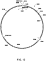
- Fig. 19 illustrates the foil bearing assembly 300 with the tab 332 of one of the inner foil pads 328 positioned adjacent to the bearing retention feature 304 of the outer foil assembly 302.
- the tab 332 is not welded or otherwise fixed to the bearing retention feature 304.
- the tab 332 may be connected to the bearing retention feature 304, for example, by welding.
- Figs. 23 and 24 also illustrate tabs 332 of the inner foil pads 328 positioned adjacent to bearing retention features 304 of the outer foil assembly 302, as described in further detail herein.
- each of the inner foil pads 328 is secured or fixed to the foil bearing assembly 300 only along the weld tab 332 such that the free end 334 of the inner foil pad 328 is free to move or deflect.
- the free end 334 of the inner foil pad 328 can improve damping characteristics of the inner foil assembly 306, for example, by allowing greater deflection or freedom of movement of the inner foil assembly 306.
- the segmented inner foil pads 328 of the inner foil assembly 306 define axially-extending gaps 340 between adjacent inner foil pads 328. These gaps 340 create discontinuities along the radial inner surface of the inner foil assembly 306, which disrupts or interrupts the swirling fluid film around the driveshaft 104. These disruptions in the swirling fluid film facilitate reducing cross-coupling within the foil bearing assembly 300, and thereby facilitate reducing sub-synchronous vibrations.
- the inner foil pads 328 can be mounted to the outer foil assembly 302 in any suitable orientation that enables the foil bearing assembly 300 to function as described herein.
- the inner foil pads 328 can be mounted in an orientation that is the same as or opposite to the direction of rotation of the driveshaft 104.
- the driveshaft 104 is configured for rotation about a rotational axis of the driveshaft 104 in a first direction (indicated by arrow 342 in Fig. 15 ).
- each of the inner foil pads 328 extends circumferentially from the tab 332 to the free end 334 in a second direction opposite the first direction 342.
- each of the inner foil pads 328 can extend circumferentially from the tab 332 to the free end 334 in the same (first) direction 342 as the rotational direction of the driveshaft 104.
- the inner foil pads 328 can also be mounted in the same orientation as the outer foil assembly 302, or in an opposite orientation than that of the outer foil assembly 302.
- the outer foil pad 318 extends circumferentially from a first end 344 including the bearing retention feature 304 to a second end 346.
- the outer foil pad 318 extends circumferentially from the first end 344 to the second end 346 in a first direction
- each of the inner foil pads 328 extends circumferentially from the tab 332 to the free end 334 in a second direction opposite the first direction.
- the inner foil pads 328 can be oriented in the same direction as the outer foil pad or pads 318. That is, each of the inner foil pads 328 can extend circumferentially from the tab 332 to the free end 334 in the same (first) direction as the outer foil pad or pads 318.
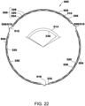
- Fig. 22 illustrates another embodiment of a foil bearing assembly 500 suitable for use with the compressor 100.
- the foil bearing assembly 500 includes an outer foil assembly 502 that includes a plurality of separate, outer foil pads 504 spaced circumferentially about the foil bearing assembly 300. More specifically, the outer foil assembly 502 includes an outer foil pad 504 for each of the inner foil pads 328 of the inner foil assembly 306. Each of the inner foil pads 328 is attached or positioned adjacent to a corresponding one of the outer foil pads 504, with one of the bump foils 320 interposed or "sandwiched" between the outer foil pad 504 and the inner foil pad 328.
- the outer foil pads 504, inner foil pads 328, and bump foils 320 define a plurality of pad modules 506, each pad module 506 including one of the outer foil pads 504, one of the inner foil pads 328, and one of the bump foils 320.
- the outer foil assembly 302 of this embodiment includes three outer foil pads 504 (corresponding to the three inner foil pads 328 of the inner foil assembly 306), although the outer foil assembly 302 can include greater than or fewer than three outer foil pads 504 in other embodiments.
- Each outer foil pad 504 is arcuate and extends circumferentially from a first end 508 including a bearing retention feature 510 (e.g., bearing retention feature 304) to a second end 512.
- Each outer foil pad 504 extends or subtends an arc angle 514 approximately equal to the arc angle 336 of the corresponding inner foil pad 328 attached to the outer foil pad 504.
- each inner foil pad 328 extends an arc angle 336 of approximately 110°
- each outer foil pad 504 extends an arc angle 514 of approximately 120°.
- the second end 512 of each outer foil pad 504 overlaps the first end 508 of an adjacent outer foil pad 504.
- the outer foil pads 504 may not overlap one another. In some embodiments, for example, each outer foil pad 504 may be separated from adjacent foil pads by a gap (e.g., similar to gap 340). Additionally, although the outer foil pads 504 are illustrated as all having the same arc angle 514 in Fig. 22 , it should be understood that the outer foil pads 504 can have different arc angles from one another.
- each of the inner foil pads 328 is welded or otherwise connected to one of the outer foil pads 504.
- each of the inner foil pads 328 is welded to one of the outer foil pads 504 along the weld tab 332 of the inner foil pad 328.
- the weld tab 332 is welded along a radial inner surface 516 of the corresponding outer foil pad 504.
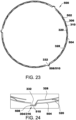
- the tab 332 of each inner foil pad 328 can be welded or positioned adjacent to a different location of the outer foil pad 504. As illustrated in Figs. 23 and 24 , for example, the tab 332 of each inner foil pad 328 is positioned adjacent to the bearing retention feature 510 of the corresponding outer foil pad 504.
- the tab 332 of each inner foil pad 328 acts as part of the bearing retention feature 304, defining a part of the axial tab 316 sized and dimensioned to interlock with a corresponding bearing assembly locking feature 208 of the bearing housing 200.
- the tab 332 of each inner foil pad 328 is not welded to the bearing retention feature 510 of the corresponding outer foil pad 504. That is, the tab 332 of each inner foil pad 328 is detached from the corresponding outer foil pad 504.
- the tab 332 of each inner foil pad 328 can be positioned adjacent to and/or in engagement with the bearing retention feature 510 of the corresponding outer foil pad 504, and inserted into a corresponding bearing assembly locking feature 208 of the bearing housing 200 to function as part of the axial tab 316.
- the tab 332 of each inner foil pad 328 is welded or otherwise connected to the bearing retention feature 510.
- the bearing housing and foil bearing assemblies of the present disclosure may be used as part of a method of assembling a compressor.
- the assembly method includes mounting the bearing housing to the compressor housing using the mounting structure of the bearing housing as described above.
- the assembly method also includes inserting a foil bearing assembly into the cylindrical bore and connecting the foil bearing assembly to the bearing housing by cooperatively engaging a bearing retention feature of the foil bearing assembly with the bearing assembly locking feature to maintain the foil bearing assembly within the bearing housing at a fixed rotational position as described above.
- connecting the foil bearing assembly to the bearing housing includes connecting a plurality of separate pad modules, each having a separate bearing retention feature, to the bearing housing.
- the method further includes inserting at least one foil retaining clip into a circumferential groove formed within the inner surface of the cylindrical bore to retain the foil bearing assembly in a fixed axial position with respect to the cylindrical bore.
- Embodiments of the systems and methods described achieve superior results as compared to prior systems and methods.
- bearing systems of the present disclosure facilitate reducing sub-synchronous vibrations (e.g., in centrifugal compressor systems) by incorporating segmented or multi-pad inner foil assemblies.
- Segmented inner foil assemblies of the present disclosure provide improved damping and reduced cross-coupled stiffness as compared to single-piece or unitary inner foil assemblies, thereby reducing sub-synchronous vibrations.
- embodiments of the segmented inner foil assemblies form axially-extending discontinuities along the radial inner foil bearing surface, which disrupt or interrupt the swirling fluid film around the shaft, thereby reducing cross-coupling within the foil bearing assembly.
- inner foil pads of the present disclosure may have different circumferential arc lengths, stiffnesses, and/or other characteristics based on a circumferential position of the inner foil pads.
- Example embodiments of bearing systems and methods such as refrigerant compressors that incorporate the disclosed bearing system and methods of assembling compressors that include the disclosed bearing assembly, are described above in detail.
- the systems and methods are not limited to the specific embodiments described herein, but rather, components of the system and methods may be used independently and separately from other components described herein.
- the bearing housing and bearing assemblies described herein may be used in compressors other than refrigerant compressors, such as turbocharger compressors and the like.
Landscapes
- Engineering & Computer Science (AREA)
- General Engineering & Computer Science (AREA)
- Mechanical Engineering (AREA)
- Physics & Mathematics (AREA)
- Fluid Mechanics (AREA)
- Structures Of Non-Positive Displacement Pumps (AREA)
- Support Of The Bearing (AREA)
Description
- This application claims priority to
U.S. Non-Provisional Patent Application Serial No. 17/167,611, filed on February 4, 2021 - The field of the disclosure relates generally to bearing systems, and more particularly, to gas foil bearing assemblies for use in compressors.
- Some refrigerants used in modern refrigeration and cooling systems, such as R134a or other low global warming potential (GWP) refrigerants, have a relatively low density which requires higher volume flow compressors such as centrifugal compressors.
- Centrifugal compressors typically include compressor bearings to support a driveshaft used to transfer power from the motor to the impeller that imparts kinetic energy to incoming refrigerant. The compressor bearings are typically provided with one or more features to reduce friction between the compressor bearing and the driveshaft. The design of these friction-reducing features of the bearings pose an on-going challenge due at least in part to the refrigerant and the challenging operating environment within gas compressors such as air conditioning compressors.
- Some compressor bearings in existing refrigerant compressors use oil or alternative compositions as a lubricant, but some refrigerants are incompatible with at least some existing lubricant compositions. Other compressor bearings are oil-free magnetic bearings that levitate the driveshaft within a magnetic field provided by high-strength magnets, but magnetic bearings are typically complex in design, add significant weight, require complicated control, and limit the choice of driveshaft materials to ferromagnetic materials in order to respond to the magnetic fields within the magnetic bearings. Another type of oil-free bearings is a foil bearing that includes compliant foil elements that surround the driveshaft and support the driveshaft on a fluid layer formed between the driveshaft and the foil elements when the rotation speed of the driveshaft exceeds a threshold speed termed liftoff speed. Foil bearings are well-suited for the high-speed operating environment typical of centrifugal compressors, are compatible with all refrigerant compositions, and may be used with a wider variety of driveshaft materials, thereby permitting the use of lighter-weight materials to reduce the amount of energy needed to operate the compressor.
- At least one consideration when using foil bearing assemblies in centrifugal compressors is sub-synchronous vibrations - i.e., vibrations occurring at a frequency below that of the rotational frequency of the shaft or other rotor supported by the bearings. Centrifugal compressors that incorporate foil bearing assemblies can be prone to sub-synchronous vibrations, which can reduce the operating envelope of the compressor.
- This background section is intended to introduce the reader to various aspects of art that may be related to various aspects of the present disclosure, which are described and/or claimed below. This discussion is believed to be helpful in providing the reader with background information to facilitate a better understanding of the various aspects of the present disclosure. Accordingly, it should be understood that these statements are to be read in this light, and not as admissions of prior art.
- In one aspect, a bearing system includes a bearing housing and a foil bearing assembly. The bearing housing includes a sleeve that defines a cylindrical bore and includes at least one bearing assembly locking feature, and a mounting structure for connecting the bearing system to a compressor housing. The foil bearing assembly is positioned within the cylindrical bore and includes an outer foil assembly, an inner foil assembly, and a bump foil assembly positioned between the outer foil assembly and the inner foil assembly. The outer foil assembly includes at least one outer foil pad extending circumferentially from a first end including a bearing retention feature to a second end. The bearing retention feature is cooperatively engaged with the at least one bearing assembly locking feature to maintain the foil bearing assembly within the bearing housing at a fixed rotational position. The inner foil assembly includes a plurality of inner foil pads spaced circumferentially about the foil bearing assembly. Each inner foil pad extends circumferentially from a tab to a free end. At least one of the inner foil pads is welded to the outer foil assembly along the tab.
- In another aspect, a compressor includes a compressor housing, a driveshaft rotatably supported within the compressor housing, an impeller connected to the driveshaft and operable to impart kinetic energy to incoming refrigerant gas upon rotation of the driveshaft, a bearing housing mounted to the compressor housing, and a foil bearing assembly rotatably supporting the driveshaft. The bearing housing includes a sleeve that defines a cylindrical bore and includes at least one bearing assembly locking feature. The foil bearing assembly is positioned within the cylindrical bore, and includes an outer foil assembly, an inner foil assembly, and a bump foil assembly positioned between the outer foil assembly and the inner foil assembly. The outer foil assembly includes at least one bearing retention feature cooperatively engaged with the at least one bearing assembly locking feature to maintain the foil bearing assembly within the bearing housing at a fixed rotational position. The inner foil assembly includes a plurality of inner foil pads spaced circumferentially about the foil bearing assembly. Each inner foil pad extends circumferentially from a tab to a free end. At least one of the inner foil pads is welded to the outer foil assembly along the tab.
- Various refinements exist of the features noted in relation to the above-mentioned aspects, within the scope of the appended claims.
- The following figures illustrate various aspects of the disclosure.
-
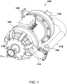
Fig. 1 is a perspective view of an assembled compressor. -
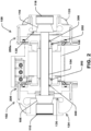
Fig. 2 is a cross-sectional view of the compressor ofFig. 1 taken along line 2-2, with the external conduit removed. -
Fig. 3 is a cross-sectional view of the compressor ofFig. 2 with the external compressor housing removed. -
Fig. 4 is a side view of an impeller mounted to an end of a driveshaft in which the driveshaft is supported by a bearing housing. -
Fig. 5 is a cross-sectional view through a sleeve of the bearing housing shown inFig. 4 taken along line 5-5, illustrating the driveshaft supported within a foil bearing assembly maintained within the sleeve of the bearing housing using a pair of retaining clips. -
Fig. 6 is a cross-sectional view of another embodiment of a bearing housing suitable for use in the compressor ofFig. 1 , illustrating the driveshaft supported within a foil bearing assembly maintained within the bearing housing between a retaining lip formed within the bearing housing at one end and a retaining clip at an opposite end. -
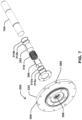
Fig. 7 is an exploded view showing the arrangement of elements of the foil bearing assembly with respect to the bearing housing and the driveshaft. -
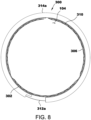
Fig. 8 is a front view of the foil bearing assembly shown inFigs. 5 and7 . -
Fig. 9 is a front view of foil bearing assembly shown inFigs. 6 and7 . -
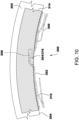
Fig. 10 is an enlarged view of the foil bearing assembly shown inFig. 9 . -
Fig. 11 is a rear view of the bearing housing shown inFig. 7 . -
Fig. 12 is a side view of the bearing housing shown inFig. 7 . -
Fig. 13 is a perspective view of the bearing housing shown inFig. 7 . -
Fig. 14 is an enlarged view of the sleeve of the bearing housing shown inFig. 10 , illustrating the bearing assembly locking feature. -
Fig. 15 is a front view of the foil bearing assembly shown inFig. 8 with the foil keeper and foil retaining clip removed. -
Fig. 16 is an enlarged view of the foil bearing assembly shown inFig. 15 , illustrating various features of the foil bearing assembly in more detail. -
Fig. 17 is a front view of another foil bearing assembly suitable for use with the compressor ofFig. 1 . -
Fig. 18 is an interior view of the foil bearing assembly shown inFig. 15 prior to the foil bearing assembly being formed into a cylinder. -
Fig. 19 is a front view of another foil bearing assembly suitable for use with the compressor ofFig. 1 , with the tab of one of the inner foil pads of the foil bearing assembly positioned adjacent to a bearing retention feature of the outer foil assembly. -
Fig. 20 is a front view of the foil bearing assembly shown inFig. 15 with inner foil pads of the foil bearing assembly mounted in a different orientation than that shown inFig. 15 . -
Fig. 21 is an interior view of the foil bearing assembly shown inFig. 20 prior to the foil bearing assembly being formed into a cylinder. -
Fig. 22 is a front view of another foil bearing assembly suitable for use with the compressor ofFig. 1 including multiple or segmented outer foil pads. -
Fig. 23 is a front view of the foil bearing assembly shown inFig. 22 , with tabs of the inner foil pads of the foil bearing assembly positioned adjacent to a bearing retention feature of the outer foil pads. -
Fig. 24 is an enlarged view of the foil bearing assembly shown inFig. 23 , illustrating various features of the foil bearing assembly in more detail. - Corresponding reference characters indicate corresponding parts throughout the drawings.
- Referring to
Fig. 1 , a compressor illustrated in the form of a two-stage refrigerant compressor is indicated generally at 100. Thecompressor 100 generally includes acompressor housing 102 forming at least one sealed cavity within which each stage of refrigerant compression is accomplished. Thecompressor 100 includes a firstrefrigerant inlet 110 to introduce refrigerant vapor into the first compression stage (not labeled inFig. 1 ), a firstrefrigerant exit 114, arefrigerant transfer conduit 112 to transfer compressed refrigerant from the first compression stage to the second compression stage, a secondrefrigerant inlet 118 to introduce refrigerant vapor into the second compression stage (not labeled inFig. 1 ), and a secondrefrigerant exit 120. Therefrigerant transfer conduit 112 is operatively connected at opposite ends to the firstrefrigerant exit 114 and the secondrefrigerant inlet 118, respectively. The secondrefrigerant exit 120 delivers compressed refrigerant from the second compression stage to a cooling system in whichcompressor 100 is incorporated. Therefrigerant transfer conduit 112 may further include arefrigerant port 122, for example, for economization. - Referring to
Fig. 2 , thecompressor housing 102 encloses afirst compression stage 124 and a second compression stage 126 at opposite ends of thecompressor 100. Thefirst compression stage 124 includes afirst impeller 106 configured to add kinetic energy to refrigerant entering via the firstrefrigerant inlet 110. The kinetic energy imparted to the refrigerant by thefirst impeller 106 is converted to increased refrigerant pressure (i.e. compression) as the refrigerant velocity is slowed upon transfer to adiffuser 136. Similarly, the second compression stage 126 includes asecond impeller 116 configured to add kinetic energy to refrigerant transferred from thefirst compression stage 124 entering via the secondrefrigerant inlet 118. The kinetic energy imparted to the refrigerant by thesecond impeller 116 is converted to increased refrigerant pressure (i.e. compression) as the refrigerant velocity is slowed upon transfer to adiffuser 138. Compressed refrigerant exits the second compression stage 126 via the second refrigerant exit 120 (not shown inFig. 2 ). - Referring to
Fig. 2 andFig. 3 , thefirst stage impeller 106 andsecond stage impeller 116 are connected at opposite ends of adriveshaft 104. Thedriveshaft 104 is operatively connected to amotor 108 positioned between thefirst stage impeller 106 andsecond stage impeller 116 such that thefirst stage impeller 106 andsecond stage impeller 116 are rotated at a rotation speed selected to compress the refrigerant to a pre-selected pressure exiting the secondrefrigerant exit 120. Any suitable motor may be incorporated into thecompressor 100 including, but not limited to, an electrical motor. Thedriveshaft 104 is supported by gasfoil bearing assemblies 300 positioned within asleeve 202 of each bearinghousing 200/200a, as described in additional detail below. Each bearinghousing 200/200a includes a mountingstructure 210 for connecting therespective bearing housing 200/200a to thecompressor housing 102, as illustrated inFig. 2 . - Referring to
Fig. 4 , each bearinghousing 200/200a (only bearinghousing 200 illustrated inFig. 4 ) supports thedriveshaft 104, and thedriveshaft 104 projects through the bearinghousing 200/200a opposite thesleeve 202, and theimpeller 106 is connected to the projecting end of thedriveshaft 104. Referring toFig. 5 andFig. 7 , the gasfoil bearing assembly 300 is positioned within acylindrical bore 206 within the bearinghousing 200. Thedriveshaft 104 closely fits within the gasfoil bearing assembly 300, which includes an outer compliant foil assembly orfoil layer 302 positioned adjacent to the inner wall of thesleeve 202, an inner compliant foil assembly or foil layer 306 (also referred to as a "top foil") positioned adjacent to thedriveshaft 104, and a bump foil assembly orfoil layer 310 positioned between theinner foil layer 306 and theouter foil layer 302. The foil assemblies or layers 302/306/310 of the gasfoil bearing assembly 300 form an essentially cylindrical tube sized to receive thedriveshaft 104 with relatively little or no gap design as determined by existing foil bearing design methods. The components of thefoil bearing assembly 300, such asouter foil layer 302, theinner foil layer 306, and thebump foil layer 310, may be constructed of any suitable material that enables thefoil bearing assembly 300 to function as described herein. Suitable materials include, for example and without limitation, metal alloys. In some embodiments, for example, each of theouter foil layer 302, theinner foil layer 306, and thebump foil layer 310 is constructed of stainless steel (e.g., 17-4 stainless steel). The foil layers can be formed from relatively thin sheets or "foils" of material. For example, the foil assemblies or layers 302/306/310 can be constructed of metal sheets having a thickness in the range of 0.003 inches to 0.007 inches. - Referring again to
Fig. 5 , thefoil bearing assembly 300 in the illustrated embodiment further includes a pair offoil keepers 312a/312b positioned adjacent opposite ends of thelayers 302/306/310 to inhibit sliding of thelayers 302/306/310 in an axial direction within thecylindrical bore 206 of thesleeve 202. A pair offoil retaining clips 314a/314b positioned adjacent to thefoil keepers 312a/312b, respectively, fix thelayers 302/306/310 in a locked axial position within thecylindrical bore 206.Foil retaining clips 314a/314b may be removably connected to bearinghousing 200.Fig. 8 further illustrates the arrangement of thefoil keeper 312a andfoil retaining clip 314a at one end of thefoil bearing assembly 300. - In other embodiments, as illustrated in
Fig. 6 , each bearinghousing 200/200a (only bearinghousing 200 illustrated inFig. 6 ) includes afoil retaining lip 214 formed integrally (e.g., cast) with the bearinghousing 200 and projecting radially inward from the radialinner surface 204 that defines thecylindrical bore 206. In the illustrated embodiment, thefoil retaining lip 214 is positioned near animpeller end 216 of thecylindrical bore 206 proximal to the impeller 116 (shown inFigs. 2-3 ). Thefoil retaining lip 214 is sized and dimensioned to project a radial distance from the radialinner surface 204 that overlaps at least a portion of thelayers 302/306/310 of thefoil bearing assembly 300. Thefoil retaining lip 214 may extend fully around the circumference of the radialinner surface 204, or the foil retaining lip can include two or more segments extending over a portion of the circumference of the radialinner surface 204 and separated by spaces flush with the adjacent radialinner surface 204. - The
foil bearing assembly 300 of the embodiment illustrated inFig. 6 further includes a singlefoil retaining clip 314 positioned adjacent the ends of thelayers 302/306/310 opposite thefoil retaining lip 214 to inhibit axial movement of thelayers 302/306/310 within thecylindrical bore 206 of thesleeve 202. In this embodiment, thefoil retaining clip 314 snaps into acircumferential groove 212 formed within the radialinner surface 204 of thecylindrical bore 206 near amotor end 218 of thecylindrical bore 206.Fig. 9 andFig. 10 further illustrate the arrangement of thefoil retaining clip 314 at one end of thefoil bearing assembly 300. Thefoil retaining clip 314 is sized and dimensioned to provide clearance for theouter layer 302, and to overlap with at least onebearing retention feature 304 that forms a radially outward projectingtab 316, as described further below. - The
foil retaining lip 214 may be positioned within any region of thecylindrical bore 206 near theimpeller end 216 including, without limitation, a position immediately adjacent to the opening of thecylindrical bore 206 at theimpeller end 216. Alternatively, thefoil retaining lip 214 may be positioned within any region of thecylindrical bore 206 near themotor end 218 including, without limitation, a position immediately adjacent to the opening of thecylindrical bore 206 at themotor end 218. In such embodiments, thefoil retaining clip 314 snaps into acircumferential groove 212 formed within the radialinner surface 204 of thecylindrical bore 206 near theimpeller end 216, in an arrangement that is essentially the opposite of the arrangement illustrated inFig. 6 . - Referring again to
Fig. 6 , thefoil bearing assembly 300 is installed within the bearinghousing 200 by inserting thefoil bearing assembly 300 into thecylindrical bore 206 of the bearinghousing 200 at themotor end 218. Thefoil bearing assembly 300 is then advanced axially into thecylindrical bore 206 toward theimpeller end 216 until thelayers 302/306/310 contact thefoil retaining lip 214. Thefoil retaining clip 314 is then snapped into thecircumferential groove 212 near themotor end 218 of thecylindrical bore 206 to lock thefoil bearing assembly 300 in place. - In other embodiments, any suitable method for affixing the
foil bearing assembly 300 within thesleeve 202 may be used. Non-limiting examples of suitable methods include keepers and retaining clips, adhesives, set screws, and any other suitable affixing method. - Referring to
Fig. 11, Fig. 12 , andFig. 13 , the mountingstructure 210 of each bearing housing 200 (only bearinghousing 200 illustrated inFig. 11, Fig.12 , andFig.13 ) /200a connects therespective bearing housing 200/200a to the compressor housing 102 (shown inFigs. 1 and2 ). In the illustrated embodiment, the mountingstructure 210 generally projects in a radially outward direction to a dimension matched to the outer dimension of thecompressor housing 102. The bearinghousing 200 may include any form of mountingstructure 210 including, without limitation, an annular flange. The bearinghousings 200/200a may further serve as a mounting structure for a variety of elements including, but not limited to, radial bearings, such as thefoil bearing assembly 300 described above, a thrust bearing, and sensing devices 250 (shown inFig. 4 ) used as feedback for passive or active control schemes such as proximity probes, pressure transducers, thermocouples, key phasers, and the like. The bearinghousing 200 may further include external coolant conduits or channels 220 (shown inFig. 11 ) to enable active cooling of the foil bearing assembly. Thecoolant channels 220 can extend, for example, radially outward from thecylindrical bore 206 to anopening 260 formed at a radial outer edge 222 of the bearinghousing 200/200a (see alsoFig. 7 ), and can deliver coolant from an external source and/or from the refrigerant system flow to the bearinghousing 200/200a andfoil bearing assembly 300. Additional details of coolant channels and coolant delivery methods suitable for use withcompressor system 100 are described, for example, inU.S. Patent Application Serial No. 16/809,836, filed March 5, 2020 - Referring to
Fig. 13 andFig. 14 , the bearinghousing sleeve 202 has a radialinner surface 204 that defines thecylindrical bore 206. The cross-sectional profile of the cylindrical bore may be essentially circular, or may be any other rounded or polygonal shape without limitation, such as elliptical, square, octagonal, and the like. The radialinner surface 204 is sized and dimensioned to receive thefoil bearing assembly 300 such that theouter layer 302 of the foil bearing assembly 300 contacts the radialinner surface 204. - Referring to
Fig. 13 , the radialinner surface 204 is provided with at least one or more additional features to enable retaining the foil bearing assembly in a fixed axial and rotational position within thesleeve 202. In some embodiments, for example, a firstcircumferential groove 212a and a secondcircumferential groove 212b are formed within the radialinner surface 204. The first and secondcircumferential grooves 212a/212b are sized and dimensioned to receivefoil retaining clips 314a and 314b, respectively, as illustrated inFig. 5 . In other embodiments, the firstcircumferential groove 212a may be replaced by a circumferential foil retaining lip 214 (seeFig. 6 ). - Referring to
Fig. 14 , the radialinner surface 204 of the bearinghousing 200 is further provided with at least one bearingassembly locking feature 208. The bearingassembly locking feature 208 interlocks with one or more bearing retention features provided on thefoil bearing assembly 300 as described below. The bearingassembly locking feature 208 may be any suitable form of mechanically interlocking feature without limitation. Non-limiting examples of suitable mechanically interlocking features include raised features such as an axial ridge, key, or tab, and axial depressions formed within the radialinner surface 204 such as an axially-extending slot, an axially-extending keyhole or keeper as illustrated inFig. 14 . The bearinghousing 200 illustrated inFig. 14 includes a single bearingassembly locking feature 208, though it should be understood that the bearinghousing 200 can include more than one bearingassembly locking feature 208. In some embodiments, for example, the radialinner surface 204 of the bearinghousing 200 defines a plurality of axially-extending grooves spaced circumferentially along the radial inner surface, each one of the axially-extending grooves sized and shaped to receive a corresponding bearing retention feature of thefoil bearing assembly 300. - Referring to
Fig. 15 and 16 , thefoil bearing assembly 300 further includes at least onebearing retention feature 304 to cooperatively engage the bearingassembly locking feature 208 to maintain the foil bearing assembly within the bearing housing at a fixed rotational position within thecylindrical bore 206 of thesleeve 202. That is, the bearingretention feature 304 and the bearingassembly locking feature 208 are sized and shaped complementary to one another such that, when thebearing retention feature 304 is engaged with the bearingassembly locking feature 208, the bearingassembly locking feature 208 inhibits or limits at least rotational movement of thebearing retention feature 304. The at least onebearing retention feature 304 may include any suitable form of mechanically interlocking feature without limitation. In some embodiments, the at least onebearing retention feature 304 is selected based on the choice of bearingassembly locking feature 208 provided within thecylindrical bore 206. Non-limiting examples of suitable mechanically interlocking features include raised features such as an axial ridge, key, or tab, as well as axial depressions formed within at least theouter foil layer 302 of thefoil bearing assembly 300 such as an axial slot, an axial keyhole or keeper. - The
foil bearing assembly 300 of the illustrated embodiment includes a singlebearing retention feature 304 formed along an edge of theouter layer 302. The bearing retention feature defines anaxial tab 316 sized and dimensioned to interlock with the bearingassembly locking feature 208, provided in the form of anaxial slot 208, as illustrated inFig. 14 . In other embodiments, thefoil bearing assembly 300 may include additional bearing retention features 304 formed, for example, along an edge of the inner layer 306 (see, e.g.,Figs. 23 and 24 ). In such embodiments, the bearing retention features 304 formed along the outer andinner layers axial tab 316. - The
foil bearing assembly 300 may be provided in any suitable form without limitation. For example, thefoil bearing assembly 300 may be provided with two layers, three layers, four layers, or additional layers without limitation. - The
outer foil assembly 302 includes at least oneouter foil pad 318. In the example embodiment illustrated inFigs. 1-16 , theouter foil assembly 302 includes a singleouter foil pad 318 constructed of a single, unitary foil. In other embodiments, theouter foil assembly 302 may be constructed of multiple outer foil pads (see, e.g.,Figs. 20-22 ). Theouter foil assembly 302 can provide a smooth inner surface for support of the adjacentbump foil assembly 310 for efficient transmission of transient motions caused by radial forces exerted by thedriveshaft 104 to theinner foil assembly 306 during operation of thecompressor 100. Theouter foil assembly 302 provides this smooth inner surface independently of the surface smoothness of the underlying radialinner surface 204 of thecylindrical bore 206 of the bearinghousing 200. Thus, in some embodiments, use of theouter foil assembly 302 facilitates increasing the surface specification of the radialinner surface 204 of thecylindrical bore 206 or, stated another way, reducing a surface smoothness requirement of the radialinner surface 204. In some embodiments, thefoil bearing assembly 300 is suitable for use with a bearinghousing 200 in an "as-cast" condition without need for further machining, grinding, or any other means to smooth the radialinner surface 204 of thecylindrical bore 206 of the bearinghousing 200. Accordingly, in some embodiments, the radialinner surface 204 of thecylindrical bore 206 is an as-cast surface. That is, the radialinner surface 204 of thecylindrical bore 206 is a surface of acast bearing housing 200 that has not undergone post-cast machining, grinding, or similar means to smooth the radialinner surface 204. - The
outer foil assembly 302 can also improve thermal management of thefoil bearing assembly 300 and facilitate reducing space requirements of thefoil bearing assembly 300, as described for example in inU.S. Patent Application Serial No. 16/809,836, filed March 5, 2020 - The
bump foil assembly 310 of thefoil bearing assembly 300 may be formed from a radially elastic structure to provide a resilient surface for the spinningdriveshaft 104 during operation of thecompressor 100. Thebump foil assembly 310 may be formed from any suitable radially elastic structure without limitation including, but not limited to, an array of deformable bumps or other features designed to deform and rebound under intermittent compressive radial loads, and any other elastically resilient material capable of compressing and rebounding under intermittent compressive radial loads. Thebump foil assembly 310 may be connected to at least one adjacent layer including, but not limited to at least one of theouter foil assembly 302 and theinner foil assembly 306. In some embodiments, thebump foil assembly 310 may be connected to both theouter foil assembly 302 and theinner foil assembly 306. In other embodiments, thebump foil assembly 310 may be free-floating and not connected to any layer of thefoil bearing assembly 300. - As shown in
Fig. 15 , thebump foil assembly 310 of the example embodiment includes a plurality of bump foils 320 spaced circumferentially about thefoil bearing assembly 300. Eachbump foil 320 extends axially the entire length or substantially the entire length of thefoil bearing assembly 300, and extends circumferentially from afirst edge 322 to asecond edge 324. Eachbump foil 320 extends or subtends an arc angle of approximately 110° from thefirst edge 322 to thesecond edge 324 in the illustrated embodiment, although the bump foils 320 may extend greater than or less than 110° around thefoil bearing assembly 300 in other embodiments. Additionally, the bump foils 320 can have different arc angles from one another. In other embodiments, thebump foil assembly 310 may include a single bump foil that extends circumferentially around the entirety or substantially the entirety of thefoil bearing assembly 300. - Each
bump foil 320 includes an axially-extendingland 326 located between thefirst edge 322 and thesecond edge 324. The bump foils 320 are secured to one or both of theouter foil assembly 302 and theinner foil assembly 306 along theland 326. In some embodiments, for example, each of the bump foils 320 is welded to theouter foil assembly 302 along arespective land 326. - The
inner foil assembly 306 forms a cylindrical inner surface that closely fits the surface of thedriveshaft 104, as illustrated inFig. 15 . Theinner foil assembly 306 includes a plurality of separate or segmentedinner foil pads 328 spaced circumferentially about thefoil bearing assembly 300. Theinner foil assembly 306 can include any suitable number ofinner foil pads 328 that enables thefoil bearing assembly 300 to function as described herein. The illustrated embodiment includes threeinner foil pads 328, although other embodiments may include greater than or fewer than threeinner foil pads 328. Each of theinner foil pads 328 is arcuate and extends circumferentially from afirst end 330 including a tab 332 (shown inFig. 16 ) to a second,free end 334. - In the embodiment illustrated in
Fig. 15 , eachinner foil pad 328 extends or subtends anarc angle 336 of approximately 110° around thefoil bearing assembly 300. In other embodiments, eachinner foil pad 328 may extend anarc angle 336 greater than or less than 110°. Additionally, in some embodiments, theinner foil pads 328 can have different arc angles from one another.Fig. 17 , for example, illustrates afoil bearing assembly 400 including aninner foil assembly 402 withinner foil pads 404 having different arc angles 406, 408. In particular, theinner foil assembly 402 ofFig. 17 includes a major inner foil pad 410 that has anarc angle 406 greater than thearc angle 408 of the otherinner foil pads 404. In this embodiment, the major inner foil pad 410 has anarc angle 406 of approximately 160°, and the otherinner foil pads 404 havearc angles 408 of approximately 95°. In other embodiments, the major inner foil pad 410 can have anarc angle 406 in the range of 120° to 360°, in the range of 120° to 270°, in the range of 120° to 240°, in the range of 120° to 200°, in the range of 120° to 180°, in the range of 120° to 150°, in the range of 150° to 360°, in the range of 150° to 270°, in the range of 150° to 240°, in the range of 150° to 200°, or in the range of 150° to 180°. - Referring again to
Fig. 15 , eachinner foil pad 328 is connected to theouter foil assembly 302 in the illustrated embodiment. In the example embodiment, eachinner foil pad 328 is welded to theouter foil assembly 302, and thetabs 332 may therefore be interchangeably referred to as weld tabs. Thetabs 332 may be welded to theouter foil assembly 302 using suitable welding techniques, such as resistance or spot welding, and laser welding. In other embodiments, theinner foil pads 328 may be connected to theouter foil assembly 302 using any other suitable fastening means. In yet other embodiments, one or more of theinner foil pads 328 may not be connected or fixed to theouter foil assembly 302. That is, one or more of theinner foil pads 328 can be detached from theouter foil assembly 302. - The
inner foil pads 328 can be welded or otherwise connected to theouter foil assembly 302 at any suitable location that enables thefoil bearing assembly 300 to function as described herein. In the example embodiment, eachinner foil pad 328 is welded to theouter foil assembly 302 along arespective weld tab 332 of theinner foil pad 328. As shown inFigs. 15 and 16 , theweld tab 332 of eachinner foil pad 328 extends radially outward from theinner foil pad 328 through an opening defined between two adjacent bump foils 320, and into engagement with theouter foil assembly 302.Fig. 18 is an interior view of thefoil bearing assembly 300 prior to thefoil bearing assembly 300 being formed into a cylinder, and illustrates theweld locations 337 for theweld tabs 332 of the inner foil pads 328 (shown schematically inFig. 18 ) between adjacent bump foils 320. Theweld tabs 332 of theinner foil pads 328 are welded to a radial inner surface 338 (Fig. 15 ) of theouter foil pad 318 in the example embodiment. In other embodiments, thetab 332 of at least one of theinner foil pads 328 can be welded or positioned adjacent to thebearing retention feature 304 of theouter foil assembly 302. -
Fig. 19 , for example, illustrates thefoil bearing assembly 300 with thetab 332 of one of theinner foil pads 328 positioned adjacent to thebearing retention feature 304 of theouter foil assembly 302. In this embodiment, thetab 332 is not welded or otherwise fixed to thebearing retention feature 304. In other embodiments, thetab 332 may be connected to thebearing retention feature 304, for example, by welding.Figs. 23 and 24 also illustratetabs 332 of theinner foil pads 328 positioned adjacent to bearing retention features 304 of theouter foil assembly 302, as described in further detail herein. - In some embodiments, each of the
inner foil pads 328 is secured or fixed to thefoil bearing assembly 300 only along theweld tab 332 such that thefree end 334 of theinner foil pad 328 is free to move or deflect. Thefree end 334 of theinner foil pad 328 can improve damping characteristics of theinner foil assembly 306, for example, by allowing greater deflection or freedom of movement of theinner foil assembly 306. Additionally, as shown inFig. 15 , the segmentedinner foil pads 328 of theinner foil assembly 306 define axially-extendinggaps 340 between adjacentinner foil pads 328. Thesegaps 340 create discontinuities along the radial inner surface of theinner foil assembly 306, which disrupts or interrupts the swirling fluid film around thedriveshaft 104. These disruptions in the swirling fluid film facilitate reducing cross-coupling within thefoil bearing assembly 300, and thereby facilitate reducing sub-synchronous vibrations. - The
inner foil pads 328 can be mounted to theouter foil assembly 302 in any suitable orientation that enables thefoil bearing assembly 300 to function as described herein. For example, theinner foil pads 328 can be mounted in an orientation that is the same as or opposite to the direction of rotation of thedriveshaft 104. More specifically, thedriveshaft 104 is configured for rotation about a rotational axis of thedriveshaft 104 in a first direction (indicated byarrow 342 inFig. 15 ). In the embodiment illustrated inFig. 15 , each of theinner foil pads 328 extends circumferentially from thetab 332 to thefree end 334 in a second direction opposite thefirst direction 342. In other embodiments (seeFigs. 20 and21 , for example), each of theinner foil pads 328 can extend circumferentially from thetab 332 to thefree end 334 in the same (first)direction 342 as the rotational direction of thedriveshaft 104. - The
inner foil pads 328 can also be mounted in the same orientation as theouter foil assembly 302, or in an opposite orientation than that of theouter foil assembly 302. For example, theouter foil pad 318 extends circumferentially from afirst end 344 including thebearing retention feature 304 to asecond end 346. In the embodiment illustrated inFig. 15 , theouter foil pad 318 extends circumferentially from thefirst end 344 to thesecond end 346 in a first direction, and each of theinner foil pads 328 extends circumferentially from thetab 332 to thefree end 334 in a second direction opposite the first direction. In other embodiments (seesFigs. 20 and21 , for example), theinner foil pads 328 can be oriented in the same direction as the outer foil pad orpads 318. That is, each of theinner foil pads 328 can extend circumferentially from thetab 332 to thefree end 334 in the same (first) direction as the outer foil pad orpads 318. -
Fig. 22 illustrates another embodiment of afoil bearing assembly 500 suitable for use with thecompressor 100. In this embodiment, thefoil bearing assembly 500 includes anouter foil assembly 502 that includes a plurality of separate,outer foil pads 504 spaced circumferentially about thefoil bearing assembly 300. More specifically, theouter foil assembly 502 includes anouter foil pad 504 for each of theinner foil pads 328 of theinner foil assembly 306. Each of theinner foil pads 328 is attached or positioned adjacent to a corresponding one of theouter foil pads 504, with one of the bump foils 320 interposed or "sandwiched" between theouter foil pad 504 and theinner foil pad 328. In this arrangement, theouter foil pads 504,inner foil pads 328, and bump foils 320 define a plurality ofpad modules 506, eachpad module 506 including one of theouter foil pads 504, one of theinner foil pads 328, and one of the bump foils 320. Theouter foil assembly 302 of this embodiment includes three outer foil pads 504 (corresponding to the threeinner foil pads 328 of the inner foil assembly 306), although theouter foil assembly 302 can include greater than or fewer than threeouter foil pads 504 in other embodiments. - Each
outer foil pad 504 is arcuate and extends circumferentially from afirst end 508 including a bearing retention feature 510 (e.g., bearing retention feature 304) to asecond end 512. Eachouter foil pad 504 extends or subtends anarc angle 514 approximately equal to thearc angle 336 of the correspondinginner foil pad 328 attached to theouter foil pad 504. In the embodiment illustrated inFig. 22 , for example, eachinner foil pad 328 extends anarc angle 336 of approximately 110°, and eachouter foil pad 504 extends anarc angle 514 of approximately 120°. In this embodiment, thesecond end 512 of eachouter foil pad 504 overlaps thefirst end 508 of an adjacentouter foil pad 504. In other embodiments, theouter foil pads 504 may not overlap one another. In some embodiments, for example, eachouter foil pad 504 may be separated from adjacent foil pads by a gap (e.g., similar to gap 340). Additionally, although theouter foil pads 504 are illustrated as all having thesame arc angle 514 inFig. 22 , it should be understood that theouter foil pads 504 can have different arc angles from one another. - In the illustrated embodiment, each of the
inner foil pads 328 is welded or otherwise connected to one of theouter foil pads 504. In the embodiment illustrated inFig. 22 , each of theinner foil pads 328 is welded to one of theouter foil pads 504 along theweld tab 332 of theinner foil pad 328. Further, in this embodiment, theweld tab 332 is welded along a radialinner surface 516 of the correspondingouter foil pad 504. In other embodiments, thetab 332 of eachinner foil pad 328 can be welded or positioned adjacent to a different location of theouter foil pad 504. As illustrated inFigs. 23 and 24 , for example, thetab 332 of eachinner foil pad 328 is positioned adjacent to thebearing retention feature 510 of the correspondingouter foil pad 504. In this embodiment, thetab 332 of eachinner foil pad 328 acts as part of thebearing retention feature 304, defining a part of theaxial tab 316 sized and dimensioned to interlock with a corresponding bearingassembly locking feature 208 of the bearinghousing 200. In the embodiment illustrated inFigs. 23 and 24 , thetab 332 of eachinner foil pad 328 is not welded to thebearing retention feature 510 of the correspondingouter foil pad 504. That is, thetab 332 of eachinner foil pad 328 is detached from the correspondingouter foil pad 504. In such embodiments, thetab 332 of eachinner foil pad 328 can be positioned adjacent to and/or in engagement with the bearingretention feature 510 of the correspondingouter foil pad 504, and inserted into a corresponding bearingassembly locking feature 208 of the bearinghousing 200 to function as part of theaxial tab 316. In other embodiments, thetab 332 of eachinner foil pad 328 is welded or otherwise connected to thebearing retention feature 510. - The bearing housing and foil bearing assemblies of the present disclosure may be used as part of a method of assembling a compressor. The assembly method includes mounting the bearing housing to the compressor housing using the mounting structure of the bearing housing as described above. The assembly method also includes inserting a foil bearing assembly into the cylindrical bore and connecting the foil bearing assembly to the bearing housing by cooperatively engaging a bearing retention feature of the foil bearing assembly with the bearing assembly locking feature to maintain the foil bearing assembly within the bearing housing at a fixed rotational position as described above. In some embodiments, connecting the foil bearing assembly to the bearing housing includes connecting a plurality of separate pad modules, each having a separate bearing retention feature, to the bearing housing. The method further includes inserting at least one foil retaining clip into a circumferential groove formed within the inner surface of the cylindrical bore to retain the foil bearing assembly in a fixed axial position with respect to the cylindrical bore.
- Embodiments of the systems and methods described achieve superior results as compared to prior systems and methods. In particular, bearing systems of the present disclosure facilitate reducing sub-synchronous vibrations (e.g., in centrifugal compressor systems) by incorporating segmented or multi-pad inner foil assemblies. Segmented inner foil assemblies of the present disclosure provide improved damping and reduced cross-coupled stiffness as compared to single-piece or unitary inner foil assemblies, thereby reducing sub-synchronous vibrations. For example, embodiments of the segmented inner foil assemblies form axially-extending discontinuities along the radial inner foil bearing surface, which disrupt or interrupt the swirling fluid film around the shaft, thereby reducing cross-coupling within the foil bearing assembly. Additionally, the multi-pad designs of the present disclosure facilitate tailoring characteristics of the inner foil assembly to enhance operation. For example, inner foil pads of the present disclosure may have different circumferential arc lengths, stiffnesses, and/or other characteristics based on a circumferential position of the inner foil pads.
- Example embodiments of bearing systems and methods, such as refrigerant compressors that incorporate the disclosed bearing system and methods of assembling compressors that include the disclosed bearing assembly, are described above in detail. The systems and methods are not limited to the specific embodiments described herein, but rather, components of the system and methods may be used independently and separately from other components described herein. For example, the bearing housing and bearing assemblies described herein may be used in compressors other than refrigerant compressors, such as turbocharger compressors and the like.
- When introducing elements of the present disclosure or the embodiment(s) thereof, the articles "a", "an", "the" and "said" are intended to mean that there are one or more of the elements. The terms "comprising," "including," "containing" and "having" are intended to be inclusive and mean that there may be additional elements other than the listed elements. The use of terms indicating a particular orientation (e.g., "top", "bottom", "side", etc.) is for convenience of description and does not require any particular orientation of the item described.
- Various changes could be made in the above constructions within the scope of the appended claims.
Claims (15)
- A bearing system comprising:
a bearing housing (200, 200a) including:a sleeve (202) defining a cylindrical bore (206) and including at least one bearing assembly locking feature (208); anda mounting structure (210) for connecting the bearing system to a compressor housing, anda foil bearing assembly (300) positioned within the cylindrical bore (206) and includingan outer foil assembly (302) including at least one outer foil pad (318) extending circumferentially from a first end including a bearing retention feature (304) to a second end,the bearing retention feature (304) cooperatively engaged with the at least one bearing assembly locking feature (208) to maintain the foil bearing assembly within the bearing housing at a fixed rotational position;an inner foil assembly (306); anda bump foil assembly (310) positioned between the outer foil assembly and the inner foil assembly;wherein the inner foil assembly (306) includes a plurality of inner foil pads (328) spaced circumferentially about the foil bearing assembly, each inner foil pad (328) extending circumferentially from a tab (332) to a free end (334),wherein at least one of the inner foil pads (328) is welded to the outer foil assembly (302) along the tab (332). - The bearing system of claim 1, wherein each of the inner foil pads (328) is welded to the outer foil assembly (302) along the tab (332).
- The bearing system of claim 1, wherein the tab (332) of at least one of the inner foil pads (328) is positioned adjacent to the bearing retention feature (304) of the at least one outer foil pad (318).
- The bearing system of claim 3, wherein the tab (332) of the at least one inner foil pad (328) positioned adjacent to the bearing retention feature (304) of the at least one outer foil pad (318) is detached from the at least one outer foil pad (318).
- The bearing system of claim 3, wherein the tab (332) of the at least one inner foil pad (328) positioned adjacent to the bearing retention feature (304) of the at least one outer foil pad (318) is welded to the bearing retention feature (304).
- The bearing system of claim 1, wherein the at least one outer foil pad (318) extends circumferentially from the first end (344) to the second end (346) in a first direction, and wherein each of the plurality of inner foil pads (328) extends circumferentially from the tab (332) to the free end (334) in a second direction opposite the first direction.
- The bearing system of claim 1, wherein the at least one outer foil pad (318) extends circumferentially from the first end (344) to the second end (346) in a first direction, and wherein each of the plurality of inner foil pads (328) extends circumferentially from the tab (332) to the free end (334) in the first direction.
- The bearing system of claim 1, wherein the bump foil assembly (310) includes a plurality of bump foils (320), and wherein the tab (332) of each inner foil pad (328) extends radially outward from the inner foil pad (328) through an opening defined between two adjacent bump foils (320) and into engagement with the outer foil assembly (302).
- The bearing system of claim 1, wherein the at least one bearing assembly locking feature (208) includes an axially-extending slot defined within the sleeve (202), and wherein the bearing retention feature (304) includes a tab that is received within the slot
- The bearing system of claim 1, wherein the mounting structure (210) includes an annular flange extending radially outward from the sleeve (202).
- The bearing system of claim 1, wherein the sleeve (202) includes a radial inner surface (204) that defines the cylindrical bore (206), wherein the radial inner surface (204) is an as-cast surface.
- A compressor (100) comprising a bearing system as claimed in any preceding claim, the compressor further comprising:a compressor housing (102);a driveshaft (104) rotatably supported within the compressor housing; andan impeller (106, 116) connected to the driveshaft (104) and operable to impart kinetic energy to incoming refrigerant gas upon rotation of the driveshaft;wherein the bearing housing (200, 200a) is mounted to the compressor housing (102), and wherein the foil bearing assembly (300) rotatably supports the driveshaft (104).
- The compressor of claim 12, wherein the driveshaft (104) is configured for rotation about a rotational axis of the driveshaft in a first direction, and wherein each of the plurality of inner foil pads (328) extends circumferentially from the tab (332) to the free end (334) in a second direction opposite the first direction.
- The compressor of claim 12, wherein driveshaft (104) is configured for rotation about a rotational axis of the driveshaft in a first direction, and wherein each of the plurality of inner foil pads (328) extends circumferentially from the tab (332) to the free end (334) in the first direction.
- The compressor of claim 12, wherein the compressor (100) comprises a first compression stage (124), a second compression stage (126), and a refrigerant transfer conduit (112) to transfer compressed refrigerant from the first compression stage (124) to the second compression stage (126); and/or wherein the compressor (100) further comprises a motor (108), and the sleeve (202) extends axially into a portion of the motor (108).
Applications Claiming Priority (2)
| Application Number | Priority Date | Filing Date | Title |
|---|---|---|---|
| US17/167,611 US11686341B2 (en) | 2021-02-04 | 2021-02-04 | Foil bearing assembly including segmented inner foil assembly and compressor including same |
| PCT/US2022/013811 WO2022169645A1 (en) | 2021-02-04 | 2022-01-26 | Foil bearing assembly including segmented inner foil assembly and compressor including this bearing assembly |
Publications (2)
| Publication Number | Publication Date |
|---|---|
| EP4264070A1 EP4264070A1 (en) | 2023-10-25 |
| EP4264070B1 true EP4264070B1 (en) | 2024-07-24 |
Family
ID=80447315
Family Applications (1)
| Application Number | Title | Priority Date | Filing Date |
|---|---|---|---|
| EP22704163.9A Active EP4264070B1 (en) | 2021-02-04 | 2022-01-26 | Foil bearing assembly including segmented inner foils assembly and compressor including this bearing assembly |
Country Status (6)
| Country | Link |
|---|---|
| US (1) | US11686341B2 (en) |
| EP (1) | EP4264070B1 (en) |
| JP (1) | JP2024506578A (en) |
| KR (1) | KR20230136750A (en) |
| CN (1) | CN116897251A (en) |
| WO (1) | WO2022169645A1 (en) |
Families Citing this family (5)
| Publication number | Priority date | Publication date | Assignee | Title |
|---|---|---|---|---|
| US12031543B2 (en) * | 2022-11-16 | 2024-07-09 | Copeland Lp | Foil bearing and driveshaft assemblies and compressor including same |
| US11852153B1 (en) | 2023-01-31 | 2023-12-26 | Copeland Lp | Foil bearing assembly including perforated inner foil assembly and compressor including same |
| USD1082858S1 (en) | 2023-08-13 | 2025-07-08 | Copeland Lp | Compressor |
| US12595821B2 (en) * | 2024-03-26 | 2026-04-07 | Copeland Lp | Foil bearing assembly including bidirectional anti-rotation features and compressor including same |
| CN120466228B (en) * | 2025-07-15 | 2025-09-16 | 上海嵘熵动力科技有限公司 | An air-suspended high-speed centrifugal fan with a hybrid bearing structure |
Family Cites Families (13)
| Publication number | Priority date | Publication date | Assignee | Title |
|---|---|---|---|---|
| US4795274A (en) | 1987-08-10 | 1989-01-03 | Allied-Signal Inc. | Foil bearing |
| US5498083A (en) | 1994-12-15 | 1996-03-12 | Air Products And Chemicals, Inc. | Shimmed three lobe compliant foil gas bearing |
| US5902049A (en) * | 1997-03-28 | 1999-05-11 | Mohawk Innovative Technology, Inc. | High load capacity compliant foil hydrodynamic journal bearing |
| US5915841A (en) | 1998-01-05 | 1999-06-29 | Capstone Turbine Corporation | Compliant foil fluid film radial bearing |
| US6964522B2 (en) | 2004-01-22 | 2005-11-15 | Honeywell International Inc. | Hydrodynamic journal foil bearing system |
| US20070047858A1 (en) | 2005-08-31 | 2007-03-01 | Honeywell International, Inc. | Foil journal bearing with bilinear stiffness spring |
| GB201122142D0 (en) * | 2011-12-21 | 2012-02-01 | Venus Systems Ltd | Centrifugal compressors |
| CN104685183B (en) * | 2012-10-17 | 2017-11-03 | 博格华纳公司 | A kind of gas dynamic pressure foil bearing component for being suitable for supporting rotatable shaft |
| FR3014512B1 (en) * | 2013-12-05 | 2016-01-15 | Liebherr Aerospace Toulouse Sas | AERODYNAMIC LEAF BEARING |
| KR102601001B1 (en) * | 2015-06-27 | 2023-11-13 | 보르그워너 인코퍼레이티드 | Air bearing arrangement for lectrically driven compressors |
| KR101785291B1 (en) * | 2016-01-26 | 2017-10-17 | 주식회사 뉴로스 | Air foil journal bearing having a improved top foil structure |
| DE112018005188T5 (en) * | 2017-11-01 | 2020-06-25 | Ihi Corporation | Centrifugal compressor |
| US11306726B2 (en) * | 2019-03-11 | 2022-04-19 | Emerson Climate Technologies, Inc. | Foil bearing assembly and compressor including same |
-
2021
- 2021-02-04 US US17/167,611 patent/US11686341B2/en active Active
-
2022
- 2022-01-26 WO PCT/US2022/013811 patent/WO2022169645A1/en not_active Ceased
- 2022-01-26 CN CN202280013112.3A patent/CN116897251A/en active Pending
- 2022-01-26 EP EP22704163.9A patent/EP4264070B1/en active Active
- 2022-01-26 KR KR1020237029078A patent/KR20230136750A/en active Pending
- 2022-01-26 JP JP2023547274A patent/JP2024506578A/en active Pending
Also Published As
| Publication number | Publication date |
|---|---|
| JP2024506578A (en) | 2024-02-14 |
| KR20230136750A (en) | 2023-09-26 |
| US20220243762A1 (en) | 2022-08-04 |
| WO2022169645A1 (en) | 2022-08-11 |
| EP4264070A1 (en) | 2023-10-25 |
| US11686341B2 (en) | 2023-06-27 |
| CN116897251A (en) | 2023-10-17 |
Similar Documents
| Publication | Publication Date | Title |
|---|---|---|
| US11306726B2 (en) | Foil bearing assembly and compressor including same | |
| US11686341B2 (en) | Foil bearing assembly including segmented inner foil assembly and compressor including same | |
| US12345271B2 (en) | Foil bearing assembly including perforated inner foil assembly and compressor including same | |
| US11608833B2 (en) | Centrifugal compressor and air conditioning equipment | |
| CA2496911C (en) | Compliant foil-fluid bearing support arrangement | |
| US10808757B2 (en) | Air bearing and rotor system | |
| EP2519716B1 (en) | Gas turbine engine and foil bearing system | |
| EP3144497A1 (en) | Electric supercharger | |
| JP2023553578A (en) | Chiller turbo compressor assembly | |
| US12595821B2 (en) | Foil bearing assembly including bidirectional anti-rotation features and compressor including same | |
| WO2024163069A1 (en) | Foil bearing assembly including perforated inner foil assembly and compressor including same | |
| US20250361872A1 (en) | Sealing system for magnetic levitating centrifugal compressor and magnetic levitating centrifugal compressor | |
| US20230228275A1 (en) | Sealing system for magnetic levitating centrifugal compressor and magnetic levitating centrifugal compressor | |
| KR102770640B1 (en) | Air Bearing For Turbomachinery | |
| US12031543B2 (en) | Foil bearing and driveshaft assemblies and compressor including same | |
| CN120759794A (en) | Rotor shaft support device and compressor |
Legal Events
| Date | Code | Title | Description |
|---|---|---|---|
| STAA | Information on the status of an ep patent application or granted ep patent |
Free format text: STATUS: UNKNOWN |
|
| STAA | Information on the status of an ep patent application or granted ep patent |
Free format text: STATUS: THE INTERNATIONAL PUBLICATION HAS BEEN MADE |
|
| PUAI | Public reference made under article 153(3) epc to a published international application that has entered the european phase |
Free format text: ORIGINAL CODE: 0009012 |
|
| STAA | Information on the status of an ep patent application or granted ep patent |
Free format text: STATUS: REQUEST FOR EXAMINATION WAS MADE |
|
| 17P | Request for examination filed |
Effective date: 20230719 |
|
| AK | Designated contracting states |
Kind code of ref document: A1 Designated state(s): AL AT BE BG CH CY CZ DE DK EE ES FI FR GB GR HR HU IE IS IT LI LT LU LV MC MK MT NL NO PL PT RO RS SE SI SK SM TR |
|
| DAV | Request for validation of the european patent (deleted) | ||
| DAX | Request for extension of the european patent (deleted) | ||
| GRAP | Despatch of communication of intention to grant a patent |
Free format text: ORIGINAL CODE: EPIDOSNIGR1 |
|
| STAA | Information on the status of an ep patent application or granted ep patent |
Free format text: STATUS: GRANT OF PATENT IS INTENDED |
|
| INTG | Intention to grant announced |
Effective date: 20240513 |
|
| GRAS | Grant fee paid |
Free format text: ORIGINAL CODE: EPIDOSNIGR3 |
|
| GRAA | (expected) grant |
Free format text: ORIGINAL CODE: 0009210 |
|
| STAA | Information on the status of an ep patent application or granted ep patent |
Free format text: STATUS: THE PATENT HAS BEEN GRANTED |
|
| AK | Designated contracting states |
Kind code of ref document: B1 Designated state(s): AL AT BE BG CH CY CZ DE DK EE ES FI FR GB GR HR HU IE IS IT LI LT LU LV MC MK MT NL NO PL PT RO RS SE SI SK SM TR |
|
| REG | Reference to a national code |
Ref country code: GB Ref legal event code: FG4D |
|
| REG | Reference to a national code |
Ref country code: CH Ref legal event code: EP |
|
| REG | Reference to a national code |
Ref country code: DE Ref legal event code: R096 Ref document number: 602022004843 Country of ref document: DE |
|
| REG | Reference to a national code |
Ref country code: IE Ref legal event code: FG4D |
|
| REG | Reference to a national code |
Ref country code: DE Ref legal event code: R082 Ref document number: 602022004843 Country of ref document: DE Ref country code: DE Ref legal event code: R082 Ref document number: 602022004843 Country of ref document: DE Representative=s name: MAIWALD GMBH, DE |
|
| REG | Reference to a national code |
Ref country code: DE Ref legal event code: R082 Ref document number: 602022004843 Country of ref document: DE Representative=s name: MAIWALD GMBH, DE |
|
| REG | Reference to a national code |
Ref country code: LT Ref legal event code: MG9D |
|
| REG | Reference to a national code |
Ref country code: NL Ref legal event code: MP Effective date: 20240724 |
|
| PG25 | Lapsed in a contracting state [announced via postgrant information from national office to epo] |
Ref country code: PT Free format text: LAPSE BECAUSE OF FAILURE TO SUBMIT A TRANSLATION OF THE DESCRIPTION OR TO PAY THE FEE WITHIN THE PRESCRIBED TIME-LIMIT Effective date: 20241125 |
|
| REG | Reference to a national code |
Ref country code: AT Ref legal event code: MK05 Ref document number: 1706536 Country of ref document: AT Kind code of ref document: T Effective date: 20240724 |
|
| PG25 | Lapsed in a contracting state [announced via postgrant information from national office to epo] |
Ref country code: NL Free format text: LAPSE BECAUSE OF FAILURE TO SUBMIT A TRANSLATION OF THE DESCRIPTION OR TO PAY THE FEE WITHIN THE PRESCRIBED TIME-LIMIT Effective date: 20240724 |
|
| PG25 | Lapsed in a contracting state [announced via postgrant information from national office to epo] |
Ref country code: PT Free format text: LAPSE BECAUSE OF FAILURE TO SUBMIT A TRANSLATION OF THE DESCRIPTION OR TO PAY THE FEE WITHIN THE PRESCRIBED TIME-LIMIT Effective date: 20241125 Ref country code: NL Free format text: LAPSE BECAUSE OF FAILURE TO SUBMIT A TRANSLATION OF THE DESCRIPTION OR TO PAY THE FEE WITHIN THE PRESCRIBED TIME-LIMIT Effective date: 20240724 |
|
| PG25 | Lapsed in a contracting state [announced via postgrant information from national office to epo] |
Ref country code: NO Free format text: LAPSE BECAUSE OF FAILURE TO SUBMIT A TRANSLATION OF THE DESCRIPTION OR TO PAY THE FEE WITHIN THE PRESCRIBED TIME-LIMIT Effective date: 20241024 |
|
| PG25 | Lapsed in a contracting state [announced via postgrant information from national office to epo] |
Ref country code: FI Free format text: LAPSE BECAUSE OF FAILURE TO SUBMIT A TRANSLATION OF THE DESCRIPTION OR TO PAY THE FEE WITHIN THE PRESCRIBED TIME-LIMIT Effective date: 20240724 Ref country code: GR Free format text: LAPSE BECAUSE OF FAILURE TO SUBMIT A TRANSLATION OF THE DESCRIPTION OR TO PAY THE FEE WITHIN THE PRESCRIBED TIME-LIMIT Effective date: 20241025 Ref country code: PL Free format text: LAPSE BECAUSE OF FAILURE TO SUBMIT A TRANSLATION OF THE DESCRIPTION OR TO PAY THE FEE WITHIN THE PRESCRIBED TIME-LIMIT Effective date: 20240724 |
|
| PG25 | Lapsed in a contracting state [announced via postgrant information from national office to epo] |
Ref country code: BG Free format text: LAPSE BECAUSE OF FAILURE TO SUBMIT A TRANSLATION OF THE DESCRIPTION OR TO PAY THE FEE WITHIN THE PRESCRIBED TIME-LIMIT Effective date: 20240724 |
|
| PG25 | Lapsed in a contracting state [announced via postgrant information from national office to epo] |
Ref country code: LV Free format text: LAPSE BECAUSE OF FAILURE TO SUBMIT A TRANSLATION OF THE DESCRIPTION OR TO PAY THE FEE WITHIN THE PRESCRIBED TIME-LIMIT Effective date: 20240724 |
|
| PG25 | Lapsed in a contracting state [announced via postgrant information from national office to epo] |
Ref country code: IS Free format text: LAPSE BECAUSE OF FAILURE TO SUBMIT A TRANSLATION OF THE DESCRIPTION OR TO PAY THE FEE WITHIN THE PRESCRIBED TIME-LIMIT Effective date: 20241124 Ref country code: AT Free format text: LAPSE BECAUSE OF FAILURE TO SUBMIT A TRANSLATION OF THE DESCRIPTION OR TO PAY THE FEE WITHIN THE PRESCRIBED TIME-LIMIT Effective date: 20240724 |
|
| PG25 | Lapsed in a contracting state [announced via postgrant information from national office to epo] |
Ref country code: HR Free format text: LAPSE BECAUSE OF FAILURE TO SUBMIT A TRANSLATION OF THE DESCRIPTION OR TO PAY THE FEE WITHIN THE PRESCRIBED TIME-LIMIT Effective date: 20240724 |
|
| PG25 | Lapsed in a contracting state [announced via postgrant information from national office to epo] |
Ref country code: RS Free format text: LAPSE BECAUSE OF FAILURE TO SUBMIT A TRANSLATION OF THE DESCRIPTION OR TO PAY THE FEE WITHIN THE PRESCRIBED TIME-LIMIT Effective date: 20241024 Ref country code: ES Free format text: LAPSE BECAUSE OF FAILURE TO SUBMIT A TRANSLATION OF THE DESCRIPTION OR TO PAY THE FEE WITHIN THE PRESCRIBED TIME-LIMIT Effective date: 20240724 |
|
| PG25 | Lapsed in a contracting state [announced via postgrant information from national office to epo] |
Ref country code: RS Free format text: LAPSE BECAUSE OF FAILURE TO SUBMIT A TRANSLATION OF THE DESCRIPTION OR TO PAY THE FEE WITHIN THE PRESCRIBED TIME-LIMIT Effective date: 20241024 Ref country code: PL Free format text: LAPSE BECAUSE OF FAILURE TO SUBMIT A TRANSLATION OF THE DESCRIPTION OR TO PAY THE FEE WITHIN THE PRESCRIBED TIME-LIMIT Effective date: 20240724 Ref country code: NO Free format text: LAPSE BECAUSE OF FAILURE TO SUBMIT A TRANSLATION OF THE DESCRIPTION OR TO PAY THE FEE WITHIN THE PRESCRIBED TIME-LIMIT Effective date: 20241024 Ref country code: LV Free format text: LAPSE BECAUSE OF FAILURE TO SUBMIT A TRANSLATION OF THE DESCRIPTION OR TO PAY THE FEE WITHIN THE PRESCRIBED TIME-LIMIT Effective date: 20240724 Ref country code: IS Free format text: LAPSE BECAUSE OF FAILURE TO SUBMIT A TRANSLATION OF THE DESCRIPTION OR TO PAY THE FEE WITHIN THE PRESCRIBED TIME-LIMIT Effective date: 20241124 Ref country code: HR Free format text: LAPSE BECAUSE OF FAILURE TO SUBMIT A TRANSLATION OF THE DESCRIPTION OR TO PAY THE FEE WITHIN THE PRESCRIBED TIME-LIMIT Effective date: 20240724 Ref country code: GR Free format text: LAPSE BECAUSE OF FAILURE TO SUBMIT A TRANSLATION OF THE DESCRIPTION OR TO PAY THE FEE WITHIN THE PRESCRIBED TIME-LIMIT Effective date: 20241025 Ref country code: FI Free format text: LAPSE BECAUSE OF FAILURE TO SUBMIT A TRANSLATION OF THE DESCRIPTION OR TO PAY THE FEE WITHIN THE PRESCRIBED TIME-LIMIT Effective date: 20240724 Ref country code: ES Free format text: LAPSE BECAUSE OF FAILURE TO SUBMIT A TRANSLATION OF THE DESCRIPTION OR TO PAY THE FEE WITHIN THE PRESCRIBED TIME-LIMIT Effective date: 20240724 Ref country code: BG Free format text: LAPSE BECAUSE OF FAILURE TO SUBMIT A TRANSLATION OF THE DESCRIPTION OR TO PAY THE FEE WITHIN THE PRESCRIBED TIME-LIMIT Effective date: 20240724 Ref country code: AT Free format text: LAPSE BECAUSE OF FAILURE TO SUBMIT A TRANSLATION OF THE DESCRIPTION OR TO PAY THE FEE WITHIN THE PRESCRIBED TIME-LIMIT Effective date: 20240724 |
|
| PG25 | Lapsed in a contracting state [announced via postgrant information from national office to epo] |
Ref country code: DK Free format text: LAPSE BECAUSE OF FAILURE TO SUBMIT A TRANSLATION OF THE DESCRIPTION OR TO PAY THE FEE WITHIN THE PRESCRIBED TIME-LIMIT Effective date: 20240724 Ref country code: SM Free format text: LAPSE BECAUSE OF FAILURE TO SUBMIT A TRANSLATION OF THE DESCRIPTION OR TO PAY THE FEE WITHIN THE PRESCRIBED TIME-LIMIT Effective date: 20240724 Ref country code: RO Free format text: LAPSE BECAUSE OF FAILURE TO SUBMIT A TRANSLATION OF THE DESCRIPTION OR TO PAY THE FEE WITHIN THE PRESCRIBED TIME-LIMIT Effective date: 20240724 |
|
| PG25 | Lapsed in a contracting state [announced via postgrant information from national office to epo] |
Ref country code: EE Free format text: LAPSE BECAUSE OF FAILURE TO SUBMIT A TRANSLATION OF THE DESCRIPTION OR TO PAY THE FEE WITHIN THE PRESCRIBED TIME-LIMIT Effective date: 20240724 |
|
| PG25 | Lapsed in a contracting state [announced via postgrant information from national office to epo] |
Ref country code: CZ Free format text: LAPSE BECAUSE OF FAILURE TO SUBMIT A TRANSLATION OF THE DESCRIPTION OR TO PAY THE FEE WITHIN THE PRESCRIBED TIME-LIMIT Effective date: 20240724 |
|
| REG | Reference to a national code |
Ref country code: DE Ref legal event code: R097 Ref document number: 602022004843 Country of ref document: DE |
|
| PG25 | Lapsed in a contracting state [announced via postgrant information from national office to epo] |
Ref country code: IT Free format text: LAPSE BECAUSE OF FAILURE TO SUBMIT A TRANSLATION OF THE DESCRIPTION OR TO PAY THE FEE WITHIN THE PRESCRIBED TIME-LIMIT Effective date: 20240724 Ref country code: SK Free format text: LAPSE BECAUSE OF FAILURE TO SUBMIT A TRANSLATION OF THE DESCRIPTION OR TO PAY THE FEE WITHIN THE PRESCRIBED TIME-LIMIT Effective date: 20240724 |
|
| PLBE | No opposition filed within time limit |
Free format text: ORIGINAL CODE: 0009261 |
|
| STAA | Information on the status of an ep patent application or granted ep patent |
Free format text: STATUS: NO OPPOSITION FILED WITHIN TIME LIMIT |
|
| 26N | No opposition filed |
Effective date: 20250425 |
|
| REG | Reference to a national code |
Ref country code: CH Ref legal event code: PL |
|
| PG25 | Lapsed in a contracting state [announced via postgrant information from national office to epo] |
Ref country code: SE Free format text: LAPSE BECAUSE OF FAILURE TO SUBMIT A TRANSLATION OF THE DESCRIPTION OR TO PAY THE FEE WITHIN THE PRESCRIBED TIME-LIMIT Effective date: 20240724 |
|
| PG25 | Lapsed in a contracting state [announced via postgrant information from national office to epo] |
Ref country code: MC Free format text: LAPSE BECAUSE OF FAILURE TO SUBMIT A TRANSLATION OF THE DESCRIPTION OR TO PAY THE FEE WITHIN THE PRESCRIBED TIME-LIMIT Effective date: 20240724 Ref country code: LU Free format text: LAPSE BECAUSE OF NON-PAYMENT OF DUE FEES Effective date: 20250126 |
|
| PG25 | Lapsed in a contracting state [announced via postgrant information from national office to epo] |
Ref country code: BE Free format text: LAPSE BECAUSE OF NON-PAYMENT OF DUE FEES Effective date: 20250131 |
|
| PG25 | Lapsed in a contracting state [announced via postgrant information from national office to epo] |
Ref country code: CH Free format text: LAPSE BECAUSE OF NON-PAYMENT OF DUE FEES Effective date: 20250131 |
|
| REG | Reference to a national code |
Ref country code: BE Ref legal event code: MM Effective date: 20250131 |
|
| PGFP | Annual fee paid to national office [announced via postgrant information from national office to epo] |
Ref country code: FR Payment date: 20251217 Year of fee payment: 5 |
|
| PG25 | Lapsed in a contracting state [announced via postgrant information from national office to epo] |
Ref country code: IE Free format text: LAPSE BECAUSE OF NON-PAYMENT OF DUE FEES Effective date: 20250126 |
|
| PGFP | Annual fee paid to national office [announced via postgrant information from national office to epo] |
Ref country code: DE Payment date: 20251217 Year of fee payment: 5 |